1. Introduction
Additive manufacturing (AM) in space has emerged as a key enabler for long-duration missions, enabling on-demand production of tools, spare parts, and experimental hardware while reducing dependency on Earth resupply. To date, in-space manufacturing has been demonstrated almost exclusively using thermoplastic extrusion processes [
1], which rely on solid filament feedstock and relatively simple melt–solidification cycles. In contrast, photopolymer-based processes such as stereolithography (SLA)—which offer superior surface quality, dimensional accuracy, and access to functional resins—remain largely unexplored in orbital environments. A critical and currently unresolved limitation is the lack of any closed-loop material management strategy for SLA resins in microgravity. SLA workflows inherently generate waste in the form of failed prints, support structures, and partially cured residues. On Earth, this waste is typically discarded due to the thermoset nature of photopolymers. In space, such an approach is unsustainable: discarded resin waste accumulates, while fresh resin must be continuously launched from Earth, increasing cost, mass, and mission risk.
Recent advances in in-space additive manufacturing have demonstrated the feasibility of producing components under microgravity conditions, including early developments in photopolymer-based processes. However, significant challenges remain in the handling, confinement, and stability of liquid resins during printing.
Within this evolving context, the present work does not address the primary printing process itself, but rather focuses on a complementary and necessary aspect, the closed-loop recycling and reconditioning of photopolymer materials, enabling more sustainable and resource-efficient operation of such systems in space environments.
The core problem addressed by the proposed project is therefore the absence of a technically viable, sealed, and microgravity-compatible method to recycle and reuse SLA photopolymer resin in orbit, closing the material loop. Research on improving sustainability in vat photopolymerization (SLA/DLP) has advanced rapidly, but most progress has focused on designing resins that are intrinsically recyclable (i.e., enabling reprocessing through dynamic covalent networks, cleavable linkages, or depolymerizable chemistries), rather than recycling today’s fully cured commercial SLA waste. For example, recent high-impact studies demonstrate re-printable/reprocessable photopolymer networks that can retain performance after reprocessing, addressing the fundamental limitation that conventional SLA resins are crosslinked thermosets and cannot be remelted or reshaped [
2]. These approaches are promising for future resin families, but they do not yet solve the near-term challenge of on-orbit waste recovery from already-qualified commercial resins, nor do they provide an integrated end-to-end microgravity-compatible recycling chain. A second active research direction targets process-side recyclability, especially for supports and sacrificial structures. Recent studies show that specially formulated supports can be dissolved and recycled over multiple cycles while maintaining printability, highlighting the feasibility of closed-loop solvent handling for vat systems under controlled conditions [
3]. While valuable, these demonstrations typically apply to engineered “recyclable support” formulations and terrestrial lab workflows, and they do not address the broader mass fraction of fully cured functional parts and failed prints that dominate SLA waste streams. In parallel, several works explore chemical routes for recovering value from polymer waste streams and enabling circularity concepts for photopolymerization more broadly (depolymerization–repolymerization paradigms and the use of recycled feedstocks for photopolymerizable systems) [
4]. However, these routes are generally developed for terrestrial settings with laboratory infrastructure and are not designed around spacecraft constraints such as strict containment, crew safety, microgravity fluid management, and limited consumables. At the application/industrial level, closed-loop thinking is increasingly visible in polymer additive manufacturing: a widely cited example is the conversion of polymer AM waste into injection-moldable feedstock for automotive components (e.g., fuel-line clips), illustrating that recycled AM polymers can be requalified into functional parts via molding [
5]. This is an important precedent for AM waste—molding feedstock—new parts value chains, but existing implementations generally involve thermoplastic AM waste streams (which are inherently more reprocessable) rather than cured SLA thermosets, and they rely on standard gravity-dependent pelletizing and molding infrastructure. The gap remains: for SLA, practical recycling typically requires size reduction, solvent-assisted dissolution, purification/filtration, degassing, and, for space, all of this must occur in a sealed, pressure/vacuum-managed architecture to control bubbles, prevent contamination, and replace gravity-driven separation mechanisms. Although significant progress has been made in recyclable photopolymer materials and process-level recycling strategies, these approaches remain limited either to newly engineered resin chemistries or to partial aspects of the SLA workflow. To clarify the distinction between existing approaches and the present work,
Table 1 provides a comparative overview of representative prior art and the proposed system architecture.
The installation presented in this work proposes a fully sealed, closed-loop system for recycling cured SLA photopolymer waste in microgravity environments. The architecture integrates mechanical fragmentation, solvent-assisted dissolution, filtration, low-vacuum degassing, intermediate pressurized storage, and pressure-driven injection into reusable molds, followed by ultraviolet post-curing. Material transport and phase control are achieved through forced mechanical conveyance and inert CO
2 overpressure, eliminating reliance on gravitational settling or buoyancy-driven separation [
11]. Each stage operates within hermetically sealed vessels equipped with pressure, temperature, and safety monitoring, ensuring containment of solids, liquids, and vapors throughout the automated cycle. By replacing gravity-dependent mechanisms with mechanically and pressure-driven processes, the installation establishes a microgravity-compatible pathway for the recovery, reconditioning, and re-fabrication of thermoset photopolymer materials within a controlled laboratory environment. The proposed system is specifically designed and optimized for operation in microgravity environments, where conventional gravity-dependent mechanisms—such as particle settling, buoyancy-driven phase separation, and hydrostatic pressure-driven flow—are ineffective or absent.
As a result, all stages of the process—fragmentation, transport, phase separation, and injection—are implemented using mechanically driven conveyance, controlled pressure differentials, and vacuum-assisted processes, ensuring reliable operation independent of gravitational forces.
While the system can also operate under terrestrial conditions, its architecture is fundamentally governed by the constraints of microgravity, particularly the need for fully sealed operation, active material transport, and controlled phase management.
2. Materials and Models: General Architecture of the Closed-Loop Installation
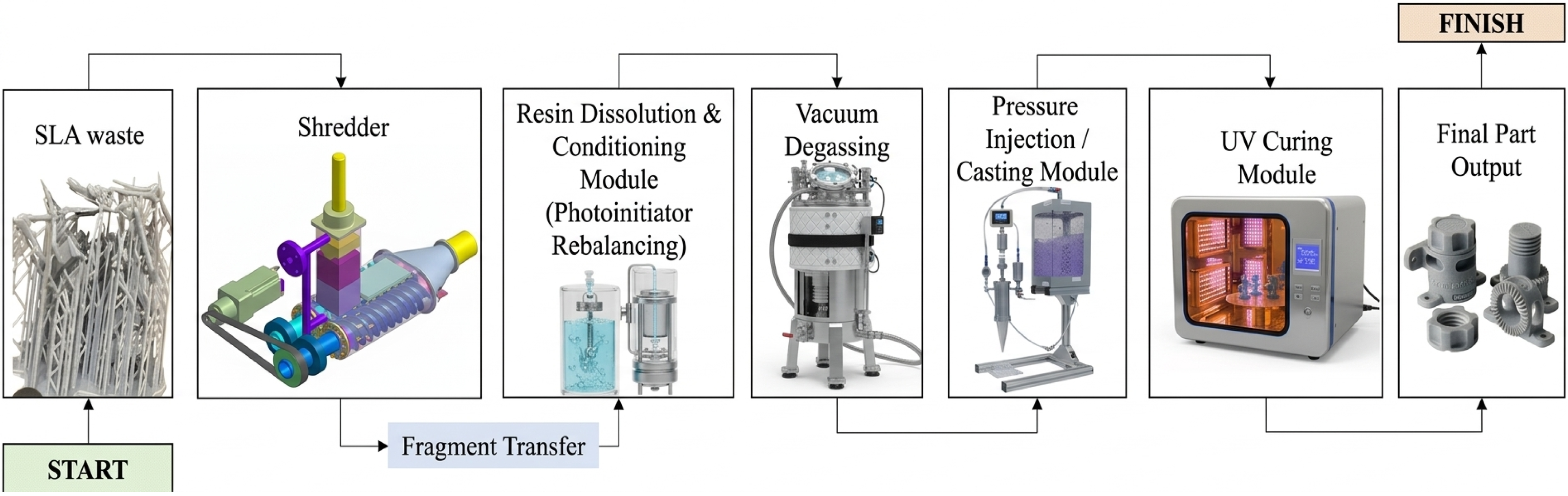
The proposed installation is conceived as a fully sealed, modular system for the recycling and re-fabrication of cured stereolithography (SLA) photopolymer waste under microgravity-compatible conditions. The architecture integrates eight functional subassemblies, denoted A–G, and associated components arranged in a sequential material-processing chain that transforms solid cured resin residues into newly formed components through controlled mechanical and physico-chemical stages. The working principle of the installation is presented in
Figure 1.
At the core of the solution is a forced and fully contained material flow, replacing gravitational settling at every stage. Fully cured SLA waste—failed prints, support structures, and end-of-life components—is first reduced in size using a compact, hermetically sealed dual-screw shredding module. Unlike conventional granulators, this module actively conveys material through counter-rotating screw elements equipped with cutting inserts, while an inert working fluid (CO2) provides simultaneous cooling, particle transport, and confinement. This enables controlled fragmentation without free-fall particles, natural convection, or open exposure—conditions that are incompatible with microgravity.
The resulting resin fragments are then transferred directly into a sealed dissolution and conditioning chamber, where solvent-assisted reprocessing occurs under controlled pressure and temperature. Photoinitiators are reintroduced during the resin dissolution and conditioning stage, where formulation rebalancing and homogeneous mixing are performed prior to vacuum degassing and pressure-driven casting.
Vacuum-assisted degassing is applied to remove entrained gases and dissolved volatiles, addressing one of the most critical challenges of liquid photopolymer handling in microgravity: bubble persistence in the absence of buoyancy. All interfaces are designed to prevent contamination of the cabin environment and to allow solvent recovery and reuse, minimizing consumables.
Material reintegration is achieved through pressure-driven injection casting, rather than gravity-fed molding or reprinting. Reconditioned resin is injected into molds using controlled overpressure, ensuring complete filling and bubble-free consolidation even in complex geometries. This approach deliberately decouples part quality from gravitational effects and enables the production of functional components using recycled material. Where required, in situ UV curing completes the re-solidification process within the same sealed architecture.
The innovation of this installation lies not in a single subsystem, but in the system-level integration of all steps required for circular SLA manufacturing in space, as schematically presented in
Figure 1. Key distinguishing features include: replacement of gravity-driven transport with active mechanical conveyance and pressure control; full containment of solids, liquids, vapors, and particulates throughout the process; compatibility with existing commercial SLA resin families, without requiring new recyclable chemistries; and direct re-entry of recovered material into a fabrication route (casting), rather than down-cycling or disposal.
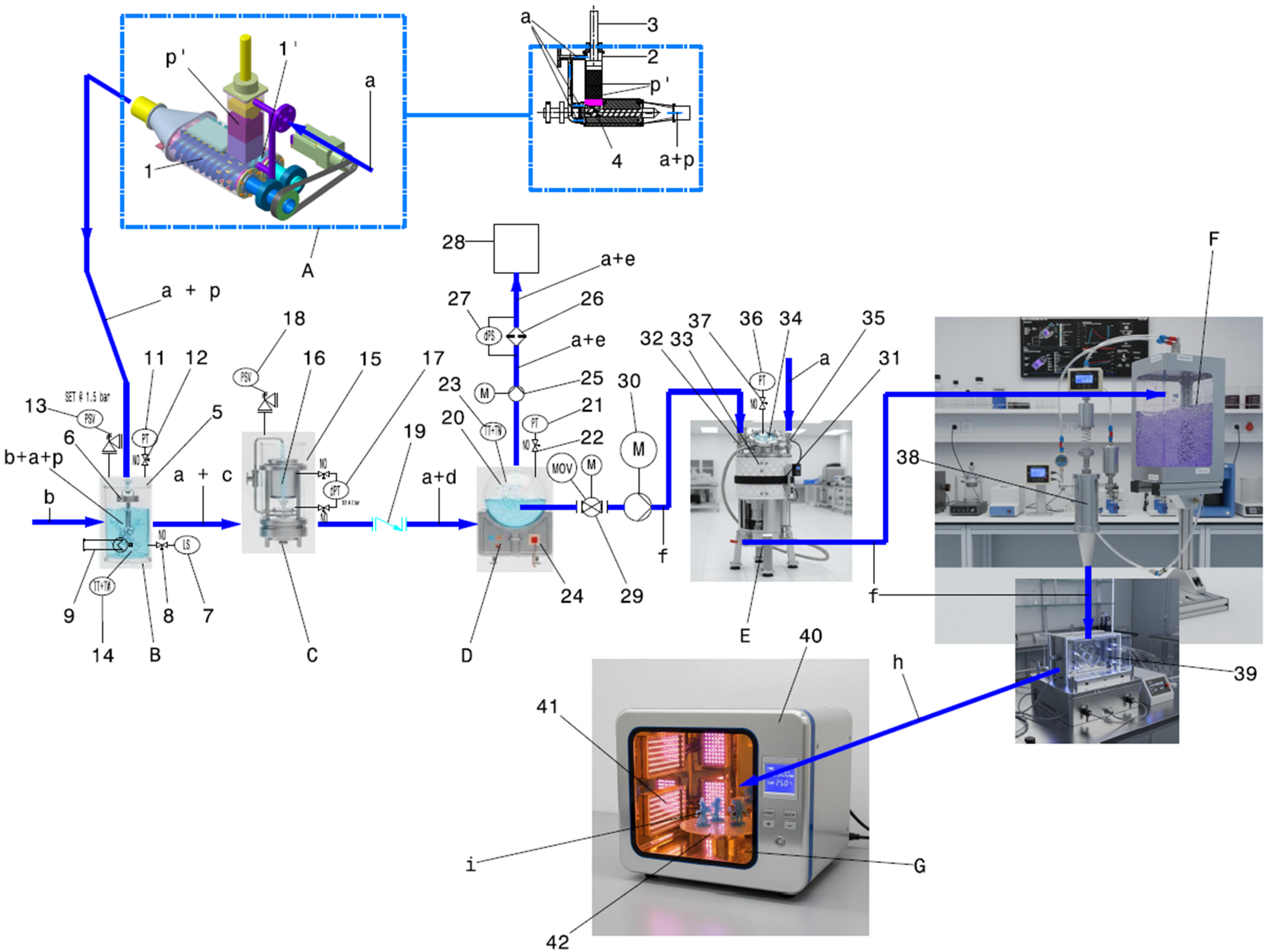
The installation containing element-level details is presented in
Figure 2.
Table 2 contains explanation of all numbering and symbols.
The operational flow begins with the introduction of solid SLA waste (p′) into the sealed fragmentation module (A), where mechanical size reduction occurs under inert-gas assistance. The resulting fragments (p) are conveyed, without gravitational dependence, into the solvent dissolution module (B), where they are combined with selected dissolution agents under controlled temperature and pressure. The dissolved mixture (c) is subsequently directed to a sealed filtration unit (C) for removal of undissolved particles, ensuring homogenization prior to gas removal. In the low-vacuum degassing module (D), entrained air, solvent vapors, and dissolved gases are extracted to prevent void formation in subsequent molding operations.
The conditioned liquid resin (f) is then transferred to an intermediate pressurized reservoir (E), which serves as a thermally stabilized buffer and pressure source. From this reservoir, the material is injected into reusable molds (F) using controlled inert-gas overpressure, thereby eliminating reliance on gravity-driven flow. Final polymerization is achieved in a dedicated ultraviolet curing module (G), completing the closed-loop cycle.
Throughout the automated stages—from fragmentation to injection—the system maintains hermetic containment of solids, liquids, and vapors. Material transport, phase separation, and flow control are achieved exclusively through mechanically driven conveyance, pressure differentials, and controlled vacuum, replacing conventional gravity-dependent mechanisms. This integrated configuration establishes a coherent and self-contained pathway for the recovery, reconditioning, and re-fabrication of thermoset photopolymer materials within a controlled microgravity-capable environment.
All elements are described in
Table 2 for ease of understanding.
2.1. Subsystem A—Sealed Fragmentation Module
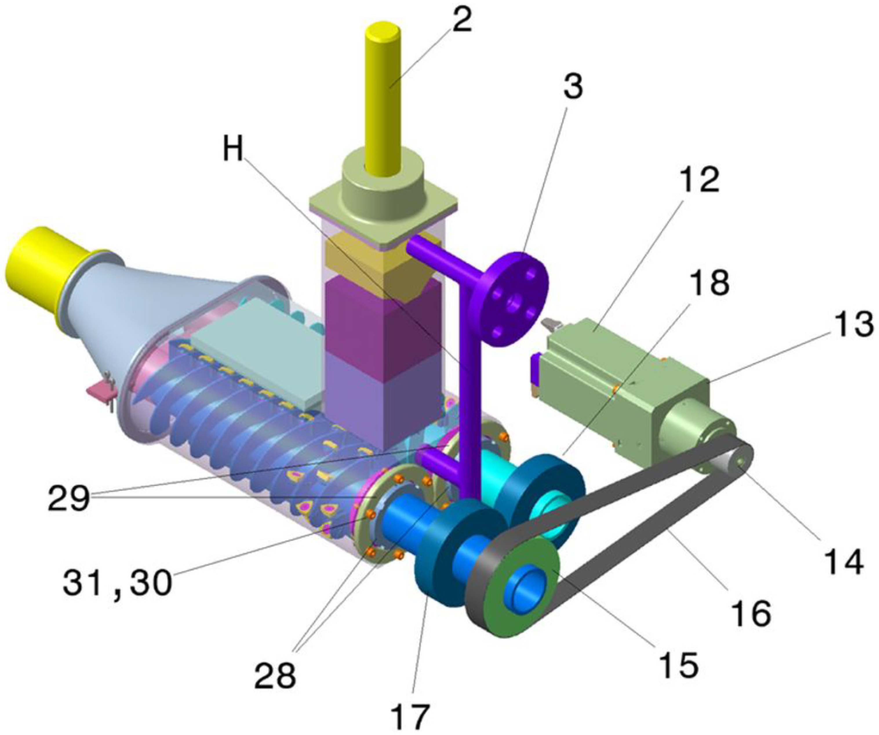
The first stage of the installation consists of a hermetically sealed mechanical fragmentation module (A) responsible for reducing fully cured SLA photopolymer waste into controlled-size fragments suitable for downstream dissolution. This module is based on the screw-type shredder previously described in detail by the authors [
11] (
Figure 3 presents the general assembly) and is here integrated as the upstream element of the closed-loop recycling architecture.
2.1.1. Structural Configuration of Subsystem A
The core of the module is the shredding chamber (A), a sealed enclosure housing two counter-rotating screw shafts (1, 1′). Each screw is equipped with helically arranged carbide cutting inserts mounted along the screw flanks. The screws rotate synchronously in opposite directions, generating a continuous shearing and conveying action along the longitudinal axis of the chamber.
At the upper interface, cured SLA waste (p′) is introduced through a sealed hopper and driven into the shredding zone by a profiled piston. The piston geometry follows the contour of the chamber to maintain minimal radial clearance, ensuring efficient volumetric loading while preventing uncontrolled particle escape. Inside the chamber, the carbide inserts initiate primary fragmentation through chipping and fracture of the thermoset material. Downstream of the main cutting zone, stationary cutters mounted along the chamber wall create a secondary shearing interface, reducing residual oversized fragments and homogenizing particle size distribution.
A pressurized inert-gas intake (CO2) is integrated into the chamber through a dedicated port. The gas serves a dual function: active cooling of the cutting interfaces and forced entrainment of the shredded particles. The combined mechanical rotation of the screws and the controlled gas flow drives the fragmented material toward the collector reduction unit and cylindrical outlet, completing the evacuation process.
The CO
2-assisted fragmentation operates under controlled low-pressure conditions (typically sub-bar to a few bar range), ensuring both particle entrainment and thermal regulation. Based on prior characterization of the shredding process [
11], the resulting fragment size distribution is typically in the range of 1–3 mm, suitable for downstream solvent-assisted dissolution and filtration stages. Larger fragments would reduce dissolution efficiency due to limited surface exposure, while excessively fine particles (e.g., below ~100 µm) may promote agglomeration, increase filtration load, and complicate fluid–particle interactions under microgravity conditions. For the target fragment size, the required gas flow is therefore moderate, with a preliminary estimate on the order of 5–20 L/min, depending on particle loading and chamber conditions. In the present architecture, the CO
2 supply is treated as an external service input, analogous to other laboratory or spacecraft utilities, and is therefore not included as a core subsystem of the installation. The gas is used primarily as an assistive mechanism, while material transport remains predominantly governed by the mechanical action of the counter-rotating screws.
The shredding module is designed to operate with partially cured or residual liquid resin, which may be present on the surface of incoming waste. To address this, the system employs a sealed feeding mechanism, limiting uncontrolled liquid entry into the cutting zone. The use of an inert CO2 stream provides continuous cooling and assists in clearing the cutting region, reducing adhesion of semi-liquid material and mitigating clogging. In addition, the counter-rotating screw configuration ensures forced material conveyance, preventing accumulation and promoting progressive fragmentation rather than compression. The mechanical components are arranged within a sealed chamber, minimizing direct exposure to liquid resin and ensuring controlled interaction between moving parts and processed material. Detailed sealing solutions and material coatings will be defined during the subsequent engineering and prototyping stages. The selected particle size distribution is therefore tailored to ensure efficient coupling between Subsystem A and Subsystem B, supporting homogeneous dispersion and stable processing in the subsequent dissolution stage.
From a mechanical standpoint, the proposed counter-rotating screw configuration is considered capable of generating the target fragment size distribution required for downstream dissolution. This feasibility arises from the combined effect of: (i) primary fracture induced by the carbide inserts mounted on the screw flanks, (ii) repeated material engagement due to counter-rotation and forced conveyance, and (iii) secondary re-cutting by the stationary cutters integrated into the chamber. Together, these mechanisms promote progressive comminution and reduce the probability of oversized fragments bypassing the shredding zone. Although the final particle size distribution remains to be established experimentally, the present geometry and cutting sequence are consistent with the intended production of controlled resin fragments suitable for solvent-assisted dissolution.
2.1.2. Microgravity Constraints and Design Rationale of Subsystem A
Conventional terrestrial shredding systems rely heavily on gravity-assisted particle fall, open discharge chutes, and passive sedimentation of fragmented material. In microgravity, such mechanisms are ineffective: solid fragments remain suspended within the chamber, debris may accumulate near rotating elements, and natural convection is absent, complicating both thermal management and particle transport. The present module addresses these constraints through forced mechanical conveyance. The counter-rotating screws do not merely cut; they actively transport fragments along a defined path, eliminating dependence on gravitational settling. The introduction of pressurized CO2 further ensures directed particle movement and prevents floating debris accumulation. In addition, the inert gas reduces thermal buildup at the cutting edges and promotes cleaner fracture of the cured resin.
2.1.3. Sealing Philosophy and Integration of Subsystem A
The fragmentation module is designed as a fully enclosed unit, maintaining containment of solids and gases throughout operation. The sealed hopper, chamber covers, bearing interfaces, and gas fittings are configured to prevent particulate release into the surrounding environment. This containment strategy is essential for operation in confined laboratory conditions and constitutes the first barrier in the overall closed-loop recycling chain.
Within the integrated installation, Subsystem A functions as the controlled entry point of the material recovery process. By converting bulky cured components into manageable fragments under sealed, gravity-independent conditions, it establishes the physical and operational basis for subsequent solvent dissolution and resin reconditioning.
2.2. Subsystem B—Solvent Dissolution Module
Following mechanical fragmentation, the shredded SLA resin fragments (p) are transferred directly into the solvent dissolution module (B), a hermetically sealed vessel designed to promote solvent-assisted softening, swelling, dispersion, and reconditioning of fragmented photopolymer waste into a processable intermediate phase suitable for downstream purification and conditioning. The extent of this transformation depends on the original resin chemistry, degree of curing, particle size, and solvent compatibility. This module constitutes the second stage of the closed-loop installation and performs controlled chemical softening and dispersion of the cured photopolymer material. Temperature control in the dissolution module is achieved through controlled heating, typically within the range of 30–70 °C, to promote solvent-assisted dissolution. Active cooling is not included in the current design, as the process does not involve significant exothermic effects and temperature can be regulated through heating control and passive heat dissipation. In the dissolution module, the pressurized gas does not constitute the primary means of mixture transport during active mixing. Homogenization is ensured by the internal agitator, whereas transfer to downstream stages is achieved subsequently through controlled pressure differentials and regulated flow paths. Consequently, the function of the gas phase in this module is supportive rather than dominant with respect to bulk liquid motion. The coupled effects of viscosity, agitation intensity, and transfer efficiency will be assessed in future experimental work.
This approach reduces system complexity and energy demand, which is particularly important for microgravity applications. However, the system architecture allows for the integration of active cooling if required in future development stages.
2.2.1. Structural Configuration of Subsystem B
The dissolution module is implemented as a sealed reservoir equipped with controlled fluid interfaces, thermal regulation, and process monitoring elements. Shredded resin fragments enter the chamber together with the inert CO2 carrier gas and are combined with selected dissolution agents, such as isopropyl alcohol (IPA), tripropylene glycol monomethyl ether (TPM), or dipropylene glycol monomethyl ether (DPM), depending on compatibility with the original resin formulation.
The vessel incorporates an internal agitator to promote homogeneous mixing and enhance solvent–polymer interaction. A heating element (resistive heater) is integrated into the chamber wall to regulate temperature and accelerate dissolution kinetics under controlled conditions. Pressure and temperature transducers monitor internal process parameters, while a safety valve provides overpressure protection. All fluid interfaces are configured to maintain full containment of solvents, vapors, and particulates.
2.2.2. Functional Role in the Recycling Chain of Subsystem B
The objective of Subsystem B is not chemical depolymerization of the thermoset network, but rather controlled softening and dispersion of the fragmented resin into a processable liquid mixture. Mechanical size reduction achieved in Subsystem A increases the effective surface area of the cured material, facilitating solvent penetration and reducing dissolution time. By operating within a sealed and temperature-controlled environment, the module ensures repeatable processing conditions and prevents uncontrolled solvent evaporation.
Unlike terrestrial recycling setups that frequently involve open solvent baths or manual handling, the present configuration maintains a closed fluid circuit. The inert CO2 stream that assists particle conveyance in the fragmentation stage continues to act as a carrier medium within the dissolution vessel, contributing to internal pressure regulation and controlled vapor management.
2.2.3. Microgravity Considerations and Sealing Philosophy of Subsystem B
In microgravity environments, phase behavior and fluid handling differ significantly from terrestrial conditions. Without buoyancy-driven separation, suspended particles do not settle naturally, and vapor accumulation may not stratify predictably. The dissolution module therefore relies on active agitation, controlled pressure, and directed flow rather than gravity-dependent sedimentation.
Hermetic sealing is maintained throughout the process to prevent solvent release into the surrounding environment. The dissolution chamber is connected downstream to the filtration module through controlled valves, allowing the dissolved mixture (c) to be transferred without exposure to the external atmosphere. This containment strategy preserves laboratory safety, protects surrounding systems from contamination, and ensures compatibility with confined operational environments.
The dissolution vessel operates under moderate continuous agitation, intended to maintain homogeneous solvent–particle contact rather than to induce high-shear dispersion. For the target fragment size range delivered by Subsystem A (1–3 mm), a preliminary design-level agitation range of approximately 50–200 rpm is considered appropriate for a compact stirred chamber, depending on solvent viscosity, solids loading, and impeller geometry. This operating window is expected to be sufficient to prevent local clustering of fragments, maintain uniform temperature and concentration fields, and promote repeatable dissolution kinetics under microgravity conditions.
In the absence of gravity-driven sedimentation, agitation in Subsystem B serves as the primary mechanism for maintaining suspension homogeneity and ensuring continuous solvent access to the resin surface. Excessive agitation is neither required nor desirable, since the objective is controlled dispersion and dissolution, not further particle size reduction. The exact agitation level will be established during future prototype testing.
Within the overall installation, Subsystem B establishes the transition from solid-phase waste to reconditioned liquid feedstock. By combining controlled thermal input, mechanical agitation, and sealed fluid handling, it prepares the material for purification and degassing in the subsequent stages of the closed-loop recycling architecture.
2.3. Subsystem C—Filtration Module
After solvent-assisted dispersion in Subsystem B, the dissolved resin mixture (c), carried together with the inert CO2 stream, is directed into the sealed filtration module (C). The function of this stage is to remove undissolved fragments, micro-particles, and residual debris generated during mechanical fragmentation, thereby ensuring a homogeneous and controlled liquid phase prior to degassing and injection.
2.3.1. Structural Configuration of Subsystem C
The filtration module is implemented as a hermetically sealed housing positioned immediately downstream of the dissolution vessel. Within this enclosure, a removable filtering element—such as a stainless-steel mesh, PTFE screen, or porous ceramic disc with a typical coarse filtration range of 100–500 µm—is mounted in a rigid support frame. The filtering element is designed to retain larger undissolved particles while allowing the conditioned liquid resin and entrained gas to pass through.
The module is equipped with a differential pressure transducer to monitor pressure drop across the filter medium, enabling detection of clogging or excessive particle accumulation. Isolation valves at the inlet and outlet allow controlled flow management and maintenance operations without exposing the system to the external environment. A safety valve provides additional protection against overpressure conditions.
2.3.2. Functional Role in the Recycling Chain of Subsystem C
The filtration stage serves as a purification and stabilization interface between dissolution and degassing. While Subsystem B promotes dispersion of fragmented resin, it cannot guarantee complete dissolution of all solid residues. The presence of larger particles or debris in subsequent modules could compromise degassing efficiency, injection quality, or mold surface integrity.
By physically separating undissolved fractions, Subsystem C ensures that only the controlled and uniform liquid phase proceeds downstream. This homogenization step improves process reliability and reduces the risk of nozzle obstruction or structural defects in the final molded component.
2.3.3. Microgravity and Containment Considerations of Subsystem C
In terrestrial filtration systems, gravity can assist sedimentation or settling prior to filtering. In microgravity environments, however, particles remain suspended within the fluid, making mechanical filtration the primary means of phase separation. The present module therefore relies exclusively on pressure-driven flow across a defined filtering interface rather than on gravitational assistance.
As with the preceding subsystems, the filtration unit is fully sealed. Solids, liquids, and vapors remain contained within the closed circuit, preventing particulate release or solvent exposure. The design ensures that collected residues can be isolated and removed during maintenance procedures without compromising the integrity of the overall installation.
Within the integrated architecture, Subsystem C represents a critical transitional stage, converting a heterogeneous dissolution mixture into a purified and process-ready resin phase. This controlled output is subsequently directed to the low-vacuum degassing module, where entrained gases and vapors are removed prior to pressurized storage and injection.
2.4. Subsystem D—Low-Vacuum Degassing Module
Following filtration, the conditioned liquid resin is transferred to the low-vacuum degassing module (D), whose primary function is the removal of entrained air, solvent vapors, and dissolved gases prior to injection. This stage is critical to ensuring the structural integrity and surface quality of the re-fabricated components, as residual gas inclusions may lead to voids, porosity, or inhomogeneous curing during molding.
The degassing process is performed under controlled low-vacuum conditions, typically in the range of 0.1–0.3 bar (absolute pressure). This pressure range is selected to promote expansion and coalescence of entrained gas bubbles while avoiding excessive solvent boiling or uncontrolled foaming of the resin–solvent mixture. The characteristic degassing time is on the order of 5–10 min, depending on the viscosity of the reconditioned resin, initial gas content, and operating temperature. Higher-viscosity formulations may require longer residence times to ensure effective gas removal.
Compared to conventional terrestrial degassing, which relies on buoyancy-driven bubble rise, the present approach enables pressure-driven gas extraction independent of gravitational effects, making it inherently suitable for microgravity operation. The controlled reduction in pressure ensures repeatable degassing performance while maintaining full containment of volatile species within the sealed system.
2.4.1. Structural Configuration of Subsystem D
The degassing module consists of a hermetically sealed chamber (20) connected to a motorized low-vacuum pump (25). The chamber is designed to operate under controlled reduced pressure, sufficient to promote expansion and release of gas inclusions without inducing excessive solvent boiling or uncontrolled foaming. Pressure within the vessel is continuously monitored through a pressure transducer (PT), while temperature is tracked via a temperature sensor (TT) protected by a thermowell.
Extracted gases and vapors are conveyed through a dedicated outlet line equipped with a filter (26) and a differential pressure sensor (27), ensuring that entrained liquid droplets or particulates do not reach the pumping system. The evacuated mixture is directed toward a buffer vessel (28) for subsequent handling. The extracted vapor and gas mixture (e), consisting of solvent vapors and inert gas, is directed to a buffer vessel (28), where it is contained within the closed system. This stage prevents release of volatile or potentially reactive species into the external environment.
The buffered gas phase may subsequently undergo conditioning processes such as condensation, separation, or recirculation, depending on system implementation. These downstream operations are not detailed in the present work but are considered compatible with the overall closed-loop architecture.
An isolation valve (29) separates the degassing chamber from the downstream intermediate reservoir, maintaining process integrity during vacuum operation.
2.4.2. Functional Role in the Recycling Chain of Subsystem D
Degassing represents the final conditioning step prior to pressurized storage and injection. During fragmentation, dissolution, and mixing, air and solvent vapors may become entrapped within the liquid resin. In terrestrial systems, buoyancy assists bubble rise and escape; however, in microgravity environments, bubbles do not naturally migrate to the surface. As a result, active pressure reduction becomes the primary mechanism for gas removal.
By lowering the internal pressure, the module promotes volumetric expansion of gas inclusions, facilitating coalescence and extraction through the vacuum line. The controlled environment ensures that the liquid phase remains contained while gaseous components are selectively removed. This process improves resin homogeneity and minimizes defect formation during subsequent molding operations.
2.4.3. Microgravity-Specific Considerations and Containment Strategy of Subsystem D
In microgravity environments, buoyancy-driven phase separation becomes negligible, and gas bubbles do not readily migrate to a free surface. Instead, bubbles tend to remain dispersed within the liquid phase unless actively removed through pressure-driven or forced-flow mechanisms, as widely reported in studies on two-phase flow in reduced-gravity conditions. Without gravitational separation, entrained bubbles may remain distributed throughout the fluid volume, increasing the likelihood of void formation in molded parts. The present module therefore replaces gravity-dependent degassing with pressure-driven phase separation under controlled vacuum conditions.
As with all preceding subsystems, the degassing chamber is fully sealed, preserving containment of solvent vapors and extracted gases. The integrated filtering and buffer arrangement ensures that no liquid resin escapes into the vacuum line, maintaining system safety and preventing contamination. Isolation valves allow the module to be decoupled from adjacent stages during operation or maintenance, preserving the integrity of the closed-loop chain. The degassing process is achieved through a combination of controlled pressure reduction, residence time, and phase disengagement within a dedicated chamber, rather than pressure variation alone.
The imposed low-pressure conditions (typically 0.1–0.3 bar) promote expansion and coalescence of entrained gas bubbles, facilitating their separation from the liquid phase. The chamber is operated under low-flow conditions, allowing sufficient residence time for gas disengagement while minimizing liquid carryover.
Gas extraction is therefore governed by the coupled effects of pressure, fluid properties, and residence time, rather than by pressure reduction alone.
Within the overall installation, Subsystem D establishes a stabilized and gas-free liquid feedstock (f), suitable for transfer to the intermediate pressurized reservoir. It represents a key microgravity-adapted stage in the architecture, ensuring that material quality is maintained independently of gravitational effects.
2.5. Subsystem E—Intermediate Pressurized Reservoir
Following degassing, the conditioned and gas-free liquid resin (f) is transferred into the intermediate pressurized reservoir (E), which functions as a buffer, stabilization, and pressure-generation unit within the closed-loop installation. This subsystem decouples upstream conditioning processes from downstream injection operations, ensuring controlled material handling and consistent injection behavior independent of gravitational effects.
2.5.1. Structural Configuration of Subsystem E
The intermediate reservoir is implemented as a hermetically sealed, pressurizable vessel (31) designed to temporarily store the degassed resin under controlled thermal and pressure conditions. The vessel is equipped with an external heating jacket (33) to maintain the resin within a defined temperature range, preventing viscosity increase or premature solidification. A transparent inspection window or lid (34) allows visual verification of fill level and material homogeneity without breaching containment. The inspection window (34) is manufactured from a chemically resistant transparent material, such as borosilicate glass or solvent-compatible polymers (e.g., polycarbonate or PMMA), selected based on compatibility with the solvent system (e.g., IPA, TPM, DPM) and the operating conditions. The material must withstand the internal pressure of the reservoir (typically 1–3 bar) and the associated temperature range (30–60 °C) without degradation or loss of mechanical integrity.
Pressurization of the reservoir is achieved through a dedicated inert-gas inlet (35), supplying CO2 at controlled pressure. Pressurisation of the reservoir is achieved through controlled injection of inert gas (CO2) through inlet (35), with a typical working pressure in the range of 1–3 bar, depending on the requirements of the injection process.
The vessel is designed to withstand pressures above the nominal operating range, with a maximum allowable pressure on the order of 4–5 bar, ensuring safe operation under transient or off-nominal conditions.
A pressure transducer (PT) monitors internal pressure, while isolation valves enable separation of the reservoir from upstream and downstream modules during operation.
The pressure transducers (PT) are selected to cover the expected operating range of the system (typically up to ~5 bar), with standard industrial accuracy suitable for process monitoring and control. The outlet of the vessel is fitted with an injection valve (32) that connects directly to the injection module.
2.5.2. Functional Role in the Recycling Chain of Subsystem E
Subsystem E performs three essential functions within the installation. First, it serves as a buffer volume, accommodating variations in upstream process timing and ensuring continuous availability of conditioned resin for injection. Second, it provides thermal stabilization of the resin, maintaining consistent rheological properties prior to molding. Third, it acts as the pressure source for resin transfer into the reusable molds.
By using inert-gas overpressure rather than mechanical pumps or gravity-driven flow, the system achieves controlled and repeatable injection conditions. This approach minimizes mechanical complexity, reduces the risk of shear-induced degradation, and ensures compatibility with microgravity environments where gravity-assisted feeding is not available.
2.5.3. Microgravity and Containment Considerations of Subsystem E
In terrestrial molding systems, resin flow into molds is often assisted by gravity or piston-driven mechanisms. In microgravity, such approaches are ineffective or introduce unnecessary mechanical complexity. The present reservoir replaces these mechanisms with pressure-driven flow, fully decoupled from orientation and gravitational direction.
Containment remains a central design principle. The pressurized vessel confines the liquid resin, inert gas, and any residual vapors within a sealed boundary. All interfaces are designed to prevent leakage and allow safe isolation during maintenance. By positioning Subsystem E between degassing and injection, the architecture ensures that only stabilized, gas-free resin is delivered to the molding stage.
The intermediate reservoir operates under controlled thermal and pressure conditions, with a typical temperature range of 30–60 °C, maintained by the external heating jacket to ensure stable viscosity and prevent premature solidification of the resin. The vessel is pressurized using inert gas (CO2), with a working pressure typically in the range of 1–3 bar, depending on the injection stage requirements.
The reservoir functions as a short-term buffer rather than a long-term storage unit, with characteristic residence times on the order of minutes to tens of minutes. This operating window minimizes the risk of premature polymerization and limits potential changes in rheological properties prior to injection.
Within the integrated installation, the intermediate pressurized reservoir represents the final conditioning and control node prior to part fabrication. It provides a stable, controllable interface between liquid processing and solid formation, enabling reliable operation of the closed-loop recycling system under microgravity-compatible conditions.
2.6. Subsystem F—Pressure-Driven Injection into Reusable Molds
Subsystem F constitutes the fabrication stage of the closed-loop installation, where the reconditioned and pressurized liquid resin is transferred into reusable molds to form new components. This module completes the automated portion of the recycling cycle and converts the stabilized liquid feedstock into a defined solid geometry prior to final ultraviolet curing.
2.6.1. Structural Configuration of Subsystem F
The injection module is directly connected to the intermediate pressurized reservoir (E) through a controlled outlet valve. Resin flow is initiated by inert-gas overpressure applied within the reservoir, eliminating the need for mechanical plungers or gravity-assisted feeding. The liquid resin (f) is directed through a conical injection nozzle (38), which ensures focused and controlled entry into the mold cavity. The reusable mold (39) is designed as a modular assembly composed of two or more rigid sections forming a closed cavity that defines the final part geometry. The mold interface is configured to withstand the applied overpressure and maintain dimensional stability during filling. The reusable mold (39) may incorporate interchangeable inserts, allowing multiple geometries to be produced within a common mold housing. The reusable mold (39) is manufactured from a chemically resistant and mechanically robust material, such as aluminum alloys, stainless steel, or high-performance polymers (e.g., PEEK), selected based on compatibility with photopolymer resins and associated solvents, as well as the required mechanical strength and thermal stability. The material must withstand repeated injection cycles under controlled pressure and temperature conditions without degradation.
This modular approach enhances manufacturing flexibility and reduces the need for multiple dedicated molds, which is particularly advantageous in space environments where mass and volume constraints are critical. Sealing surfaces and mechanical clamping elements ensure containment of the injected resin throughout the molding phase.
2.6.2. Functional Role in the Recycling Chain of Subsystem F
The purpose of Subsystem F is to reintroduce the conditioned resin into a manufacturing pathway, thereby closing the material loop. Unlike conventional stereolithography, which builds parts layer by layer, the present installation employs pressure-driven casting into predefined molds. This approach allows the use of reconditioned resin without requiring reprinting in a vat-based system and avoids the complexities associated with free-surface liquid management in microgravity.
The pressure-driven filling mechanism ensures that resin flow is governed exclusively by controlled overpressure rather than gravitational head. This enables consistent mold filling regardless of system orientation and prevents incomplete cavity filling due to the absence of buoyancy or hydrostatic pressure gradients.
2.6.3. Microgravity and Containment Considerations of Subsystem F
In terrestrial casting operations, gravity assists both resin flow and bubble migration within the mold cavity. In microgravity environments, neither effect can be relied upon. The present system compensates for this by applying controlled inert-gas overpressure, which drives resin into the mold and promotes uniform cavity filling. Prior degassing in Subsystem D ensures that the injected resin contains minimal entrained gas, reducing the risk of void formation.
Containment remains continuous throughout the injection process. The resin remains confined within the pressurized reservoir, nozzle, and sealed mold assembly. Human intervention occurs only after the automated injection phase is completed and the mold has been safely isolated from the pressurized circuit. It should be noted that fully cured thermoset photopolymers do not inherently regain their original reactivity after dissolution or swelling. As such, the re-fabrication step is dependent on the chemical nature of the processed material, including the presence of partially cured fractions, residual reactive groups, or the potential addition of photoinitiators or reactive modifiers. The proposed system therefore enables material reconditioning rather than full molecular reversal, and the effectiveness of subsequent UV curing is expected to vary depending on resin formulation. This aspect requires experimental validation and optimization in future work.
Within the integrated architecture, Subsystem F represents the transformation point from liquid-phase material conditioning to solid part formation. By employing pressure-driven injection independent of gravity, the module ensures reliable and repeatable fabrication under microgravity-compatible conditions while maintaining the sealed philosophy of the installation.
2.7. Subsystem G—UV Curing Module
Subsystem G represents the final stage of the material transformation process, in which the injected resin is fully polymerized to obtain the final solid component. While the preceding subsystems operate as part of a sealed and automated recycling chain, the UV curing module constitutes a controlled post-processing stage that completes photochemical solidification after mold filling.
2.7.1. Structural Configuration of Subsystem G
The UV curing module is implemented as an enclosed curing chamber (40) equipped with ultraviolet light sources (41), typically operating at wavelengths of 385 nm or 405 nm, consistent with common SLA photoinitiator activation ranges. The chamber incorporates a rotating platform (42) on which the molded components are placed to ensure uniform exposure to UV radiation from multiple directions.
The curing chamber is structurally separated from the pressurized injection circuit. After resin injection and mold filling are completed in Subsystem F, the mold is isolated from the pressurized line and opened under controlled conditions. The molded component (h) is then transferred into the UV chamber, where final polymerization is achieved through uniform photo-exposure.
2.7.2. Functional Role in the Recycling Chain of Subsystem G
Although the injected resin has undergone prior conditioning and degassing, complete crosslinking and mechanical stabilization require controlled ultraviolet exposure. The curing stage ensures that any residual reactive groups are polymerized, resulting in dimensional stability, surface hardness, and structural integrity comparable to conventionally cured SLA components.
By isolating the curing step from the liquid-handling subsystems, the architecture maintains a clear separation between sealed recycling operations and final solidification. This separation reduces risk of contamination of liquid-processing stages while allowing controlled access to the formed parts.
2.7.3. Integration Within the Closed-Loop Architecture of Subsystem G
Subsystem G completes the circular workflow of the installation. The process sequence—fragmentation, dissolution, filtration, degassing, pressurized storage, injection, and curing—transforms cured waste material into a newly solidified component within a contained and microgravity-compatible framework.
Unlike vat-based SLA systems, which require continuous liquid-surface control and layer-by-layer curing, the present architecture performs curing after pressure-driven casting into a defined mold geometry. This approach avoids the complexities associated with free-surface resin behavior in reduced gravity and enables reliable part formation independent of gravitational orientation.
Within the overall system, the UV curing module represents the final material stabilization stage, closing the loop from solid waste (p′) to re-fabricated solid components (i) under controlled photochemical conditions.
3. Discussion
The complete installation operates as a sequential, pressure-controlled material recovery chain, transforming cured SLA waste (p′) into newly fabricated solid components (i) through a series of mechanically and physically coupled stages. While the preceding sections described each subsystem individually, the present section outlines their coordinated operation within a unified closed-loop workflow.
The cycle begins with the introduction of cured photopolymer residues into the sealed fragmentation module (A). Mechanical size reduction is achieved through the counter-rotating screw mechanism under inert CO2 assistance, producing controlled resin fragments (p) that are forcibly conveyed toward the dissolution module (B). The absence of gravitational reliance is ensured by continuous mechanical transport and gas-assisted particle entrainment.
Within the dissolution module, shredded fragments are dispersed in a controlled solvent environment under regulated temperature and pressure conditions. The resulting mixture (c) is then transferred to the filtration module (C), where undissolved particles are mechanically separated to obtain a homogenized liquid phase. This purified mixture enters the low-vacuum degassing module (D), where entrained gases and solvent vapors are removed through controlled pressure reduction, yielding a stabilized liquid resin (f).
The degassed resin is subsequently stored in the intermediate pressurized reservoir (E), which provides thermal stabilization and generates the inert-gas overpressure required for injection. From this reservoir, the material is transferred into reusable molds (F) through pressure-driven flow, independent of gravitational orientation. After mold filling and isolation from the pressurized circuit, the molded components are transferred to the ultraviolet curing module (G), where final polymerization is completed.
Throughout the automated stages—from fragmentation to injection—the system maintains hermetic containment of solids, liquids, and vapors. Material movement is governed exclusively by mechanical conveyance, controlled pressure differentials, and regulated vacuum conditions. By replacing gravity-dependent sedimentation, buoyancy, and hydrostatic flow with actively driven mechanisms, the installation establishes a coherent and microgravity-compatible closed-loop pathway for photopolymer recycling and re-fabrication.
4. Conclusions
This work proposes a closed-loop system architecture for the recycling and re-fabrication of photopolymer resins in microgravity environments, addressing a key limitation of current stereolithography-based manufacturing processes.
The main contribution of this study lies in the integration of multiple process stages—fragmentation, dissolution, filtration, degassing, pressurized storage, and injection—into a fully sealed and gravity-independent system. Unlike terrestrial approaches, the proposed architecture replaces gravity-driven mechanisms with mechanical conveyance and pressure-controlled transport, enabling reliable operation under reduced-gravity conditions.
The proposed system is currently developed at a conceptual and design stage and therefore has several limitations that must be acknowledged.
First, the absence of experimental validation means that the performance of individual subsystems and the integrated process has not yet been quantitatively assessed. Key parameters such as dissolution efficiency, degassing effectiveness, and final material properties remain to be confirmed through prototype testing.
Second, the system relies on solvent-assisted processing, which introduces additional complexity related to solvent management, recovery, and long-term compatibility with system materials.
Third, the process is sensitive to operating conditions, including temperature, pressure, and particle size distribution, which must be carefully controlled to ensure stable and repeatable performance.
Additionally, the current architecture assumes the availability of supporting infrastructure (e.g., inert gas supply and thermal control), which may impose constraints depending on the specific deployment environment.
Finally, the range of compatible photopolymer resins may be limited by their chemical composition and response to dissolution and reprocessing, which could affect the generality of the approach.
These limitations will be addressed in future work through experimental validation, system optimization, and material compatibility studies.
A key aspect of the system is the use of controlled particle size reduction and solvent-assisted processing, combined with low-pressure degassing and pressure-driven injection, ensuring process continuity and material containment throughout the cycle. The architecture is also compatible with modular and reconfigurable manufacturing approaches, such as interchangeable mold inserts, supporting flexible in situ production.
The present work is developed at a conceptual and design stage and therefore does not include experimental validation. Future work will focus on prototype development, experimental characterization of process parameters, and evaluation of material properties of the recycled resin, as well as system optimization for space deployment.
Overall, the proposed system establishes a technically feasible pathway toward closed-loop material reuse in space-based additive manufacturing, with potential impact on resource efficiency, mission autonomy, and waste reduction.
5. Patents
Patent application has been filled for the recycling system at the Romanian State Office for Inventions and Trademarks: Closed-Loop Recycling System for Photopolymer Resins Operable in Microgravity Environments, Prisăcariu, E.G.; Vlăducă, I. Patent application A/0551, Romania, filed 24 November 2025.