


Abstract
This work presents a covariance-aware extension of the hybrid nonlinear-kicker (NLK) injection framework. While previous baseline studies established centroid action reduction and hardware-aware NLK placement for idealized beams, the present study addresses finite-beam optimization using a realistic, position-dependent eight-wire kick profile. A realistic NLK field not only corrects the injected-beam centroid but also induces an amplitude-dependent shear across the internal phase-space ellipse. Depending on the injected covariance and ellipse orientation, this shear can either reduce or enhance beam filamentation. To exploit this mechanism, the AC-septum angle is treated as a trajectory-control knob for the injected centroid, while transfer-line matching is used to control the injected covariance matrix. We use ID2-downstream as the primary optics-favored case, as its high simultaneously increases nonlinear-field sampling and reduces the required correction kick. Furthermore, at this location, the injected beam is close to a matched, near-upright covariance condition (). We also examine ID1 middle and ID1 downstream as trajectory-controllable alternatives, and formulate a combined optimization over septum angle, transfer-line optics, and NLK current. Operational measurements of AC-septum stability, first-turn trajectory reproducibility, septum response, and injection-bump response validate the available trajectory-control authority required for realistic NLK optimization. The analysis identifies a residual oscillation floor proportional to the square of the remaining centroid offset and inversely proportional to the local beta function, demonstrating that the physically relevant objective is minimization of the final mean action after the realistic NLK kick, rather than percentage action reduction alone. This framework establishes a practical optimization strategy under realistic aperture, stability, and hardware constraints. In a representative covariance-matched ID2D case, the realistic eight-wire NLK reduces both mean horizontal action (from 3.372 μm to 0.382 μm) and finite-beam spread contribution (from 0.475 μm to 0.039 μm). Operationally, first-turn rms trajectory variations remain under 0.4 mm, and the measured trajectory response of 19.4 mm/mrad closely matches the 19.8 mm/mrad model.
1. Introduction
The baseline hybrid-NLK framework identifies promising installation locations using centroid action-angle response, injected-beam offset, local beta functions, aperture margins, and hardware feasibility constraints [1]. However, multi-particle tracking with the realistic eight-wire NLK field profile shows that finite beam-size effects can significantly reduce the ideal centroid correction. Because particles within the injected distribution experience different field strengths across the nonlinear kick profile, the realistic nonlinear field shears the internal phase-space distribution and can change the beam covariance after the kick. Many existing NLK design studies optimize the centroid trajectory, injection efficiency, or kicker amplitude, whereas the finite-beam covariance response is often treated through tracking rather than as an explicit optimization variable [1,2,3,4,5,6,7]. Realistic NLK performance fundamentally depends on characterizing the full phase-space covariance at the NLK location, as this dictates how the particle distribution samples local field gradients and higher-order curvature. The present study is a direct continuation of the baseline hybrid-NLK framework developed in Ref. [1], extending its centroid- and hardware-oriented treatment to finite-beam covariance optimization and measured trajectory-control authority. Specifically, it introduces final mean action as a covariance-aware objective and quantitatively validates the trajectory-control authority for the NSLS-II hybrid injection scheme.
This covariance-aware formulation builds on a broader body of nonlinear-kicker and pulsed-multipole injection studies at several synchrotron light sources [2,3,4,5,6,7]. At BESSY II, beam-based NLK optimization, together with optimized sextupole settings, achieved injection efficiencies up to 97%, approaching routine four-kicker performance [2]. At Sirius, the sensitivity of NLK injection to finite horizontal beam size motivated emittance control and exchange to improve injection efficiency [3,4]. ESRF-EBS is developing an NLK-based injection upgrade involving coordinated modification to the transfer line, storage-ring optics, and kicker hardware [5,6], while TPS is evaluating an NLK prototype with transfer-line reconfiguration [7]. These studies show that practical NLK performance depends not only on the nonlinear field, but also on the injected trajectory, beam phase-space properties, and lattice optics.
Diffraction-limited storage rings employ strong nonlinear focusing and small insertion-device apertures, reducing the acceptance available for conventional off-axis injection [8,9]. Alternative approaches include optimized multi-kicker bumps, pulsed-multipole and NLK injection [2,3,4,5,6,7,8,9,10,11,12,13], off-energy or longitudinal injection [14], and on-axis swap-out injection [15,16]. Each involves different trade-offs among stored-beam transparency, dynamic-aperture requirements, injector complexity, and hardware integration. In particular, swap-out and other on-axis schemes can accommodate the substantially reduced transverse acceptance of diffraction-limited storage rings, but may require additional injector, beam-dump, fast-kicker, and timing infrastructure. The hybrid NLK approach considered here instead retains the existing septum and four-kicker bump while adding a downstream, stored-beam-transparent correction to reduce the injected first-turn action.
At NSLS-II, the existing AC-septum and four-kicker injection system provides a mature and reliable baseline, while the reduced acceptance anticipated for a future high-brightness upgrade motivates a compact retrofit that reduces injected-beam action without fundamentally changing this architecture or perturbing the stored beam. The remaining challenge addressed in this work is that a realistic nonlinear field acts on the full injected distribution rather than on its centroid alone; consequently, practical optimization must account for both centroid field sampling and the covariance-dependent response of the finite beam.
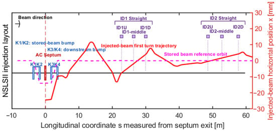
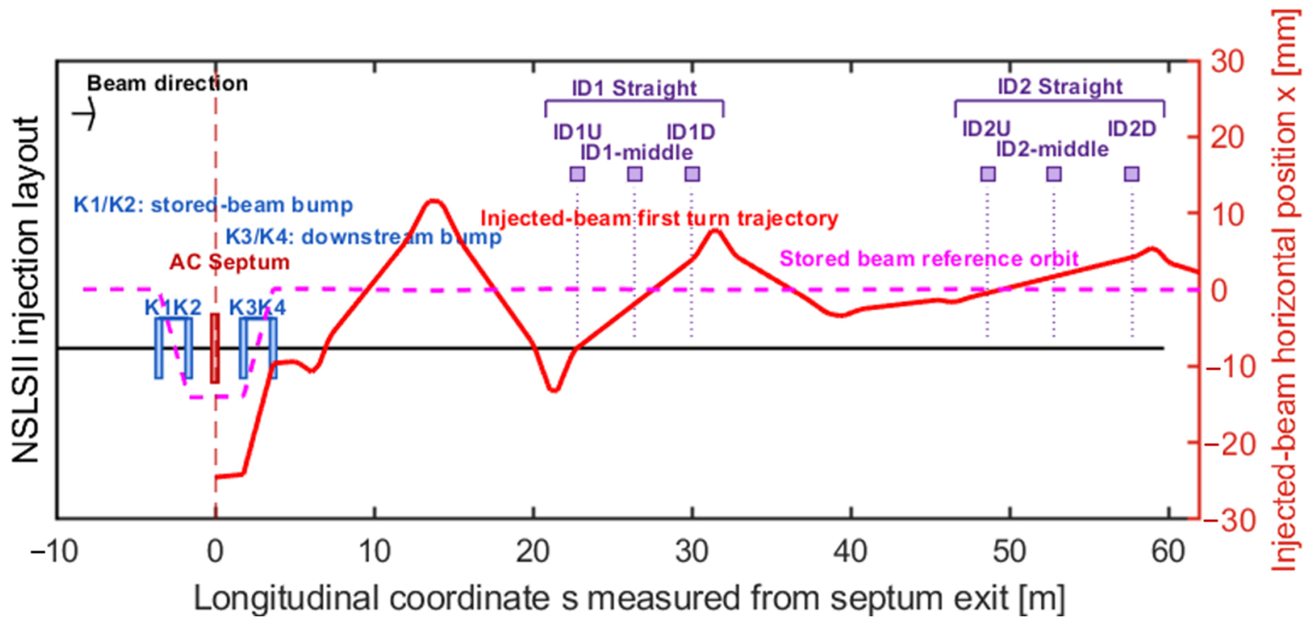
The objective of this study is to formulate an optimization framework that incorporates these finite-beam effects. For a fixed NLK location, the AC septum primarily controls the first-turn centroid trajectory and therefore the region of the NLK field sampled by the beam. In contrast, transfer-line matching modifies the beam ellipse, altering the finite-beam response to local field gradients and curvature. The resulting optimization treats centroid trajectory, finite-beam covariance, and realistic nonlinear-field sampling as coupled variables. Figure 1 summarizes the NSLS-II injection geometry and candidate NLK locations. Longitudinal position is referenced to the AC-septum exit (); K3 and K4 are the two injection-bump kickers downstream of the septum. The candidate locations span the first two downstream insertion-device straights, with U, middle, and D denoting upstream, middle, and downstream positions, respectively. The modeled first-turn injected-beam trajectory illustrates how the available horizontal offset varies substantially with longitudinal position, enabling different field-sampling conditions at the candidate NLK locations.
Figure 1.
Schematic of the NSLS-II injection sector referenced to the AC-septum exit (). The existing downstream injection-bump kickers K3 and K4, stored-beam reference orbit, modeled first-turn horizontal injected-beam trajectory (red), and candidate NLK locations are shown. ID1U, ID1-middle, and ID1D denote the upstream, middle, and downstream candidate positions in the first insertion-device straight; ID2U, ID2-middle, and ID2D denote the corresponding positions in the second straight. Longitudinal coordinates are measured from the septum exit. Among these locations, the detailed optimization presented below focuses on ID2D as the preferred baseline and ID1-middle and ID1D as trajectory-controllable alternatives.
Although the numerical examples and measured responses in this work are specific to the NSLS-II hybrid injection system, the covariance-aware formulation is not facility-specific. It applies to any off-axis NLK injection scheme in which the injected centroid trajectory and covariance can be controlled. Facility-specific information enters through the transport map, local storage-ring optics, realistic kicker field map, aperture constraints, and available operational knobs.
Section 2 develops the covariance-aware NLK model and the local shear-matching condition. Section 3 analyzes beta-function scaling, realistic-field sampling, and AC-septum control at ID1 and ID2. Section 4 quantifies the available trajectory leverage and reports the machine measurements. Section 5 formulates the combined centroid-and-covariance optimization at fixed ID2D. Section 6 compares the preferred and fallback operating branches. The final section discusses applicability, limitations, and the principal conclusions.
2. Covariance-Aware NLK Model
2.1. Normalized-Coordinate Description of the Injected Beam
At a candidate NLK location, define the local normalized coordinates using the storage-ring Twiss parameters and :
For the injected centroid,
The normalized-coordinate representation and associated Courant–Snyder invariant follow the standard formulation of linear beam optics [17,18,19]. For a finite injected beam, the covariance matrix in physical horizontal phase-space coordinates (x, x′) is = . Transformation into normalized coordinates gives
The off-diagonal term , together with the corresponding normalized ellipse tilt, characterizes whether the injected beam is upright or tilted at the NLK. This distinction is important because the realistic NLK field gradient acts as a local shear in normalized phase space, making the beam response sensitive to the ellipse orientation.
Throughout this work, x [m] and x′ [rad] denote horizontal position and angle relative to the stored-beam reference orbit; [m], , and are the local storage-ring Twiss parameters at the NLK; and are the normalized coordinates; [m] is the Courant–Snyder action; and are the physical and normalized 2 × 2 covariance matrices; [rad] is the thin-lens NLK kick; is the injected centroid position; is the particle displacement from the centroid; and angle brackets denote an average over the injected particle distribution.
2.2. Realistic Eight-Wire NLK Field as a Phase-Space Shear
A thin NLK kick changes x′ while leaving x unchanged. In normalized coordinates,
Expanding the realistic kick profile about the beam centroid position gives
Substituting , the normalized-angle deviation becomes:
where . The centroid term provides the coherent correction, whereas the linear term shears the internal phase-space distribution by modifying the X-P correlation. For a favorable field-slope sign, this shear can partially compensate the incoming ellipse tilt and reduce the mean action. For the opposite sign, it increases the angular spread and enhances filamentation.
Neglecting curvature, the contribution of the finite beam size to the post-kick action is approximately
Minimizing Equation (6) yields the local ellipse-matching condition
Equation (7) provides a simple interpretation of the scan results: optimal finite-beam performance is achieved when the local NLK field slope is matched to the tilt of the injected-beam ellipse. The covariance-based interpretation is closely related to conventional beam-mismatch and filamentation analyses, where phase-space correlations determine the evolution of beam quality under linear and nonlinear transport [18,19]. Curvature terms proportional to introduce an irreducible finite-beam penalty and must be evaluated using the full eight-wire field map.
Equation (7) can also be expressed directly in terms of the injected Twiss parameter by substituting the standard covariance parameterization into Equation (3), making the connection to the optimization variable used in the scans explicit. Using the injected-beam covariance = , one obtains and . Therefore, , with . This relation directly connects the local NLK field slope sampled by the beam centroid to the transfer-line Twiss parameter varied in the optimization. For the case considered in the illustrative ID2D examples, a negative local field slope therefore corresponds to a negative optimal, consistent with the numerical optimization.
The curvature-free approximation in Equation (6) is used only for local physical interpretation. It is valid when the NLK field is approximately linear over the populated transverse region, such that ≪, where is the characteristic half-width about the centroid. Here, n = 3 represents the approximately ±3 region of a Gaussian beam. The centroid must also remain away from a field extremum, where becomes small. When these conditions are not satisfied, quadratic and higher-order terms contribute appreciably. Accordingly, all numerical optimization and particle tracking use the complete eight-wire field profile; the linearized expression is used only for physical interpretation.
3. Physical Mechanisms at ID2D
Our baseline study identified ID2D as a favorable NLK location based on optics performance and current-scaling considerations [1]. The subsequent finite-beam simulations show that realistic injection performance depends additionally on the injected-beam ellipse orientation, AC-septum-controlled field sampling, and the available NLK polarity and current. This section summarizes the underlying physical mechanisms and motivates the combined optimization framework.
3.1. Beta-Function Scaling and Kick-Capping
For , the physical centroid coordinates corresponding to fixed normalized action (J) and phase () satisfy Thus, increasing increases the transverse offset sampled by the NLK while reducing the correction angle required for the same normalized action and phase. This scaling provides a useful physical explanation for why high- locations can be favorable for nonlinear-kicker injection.
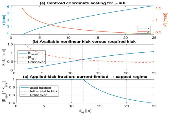
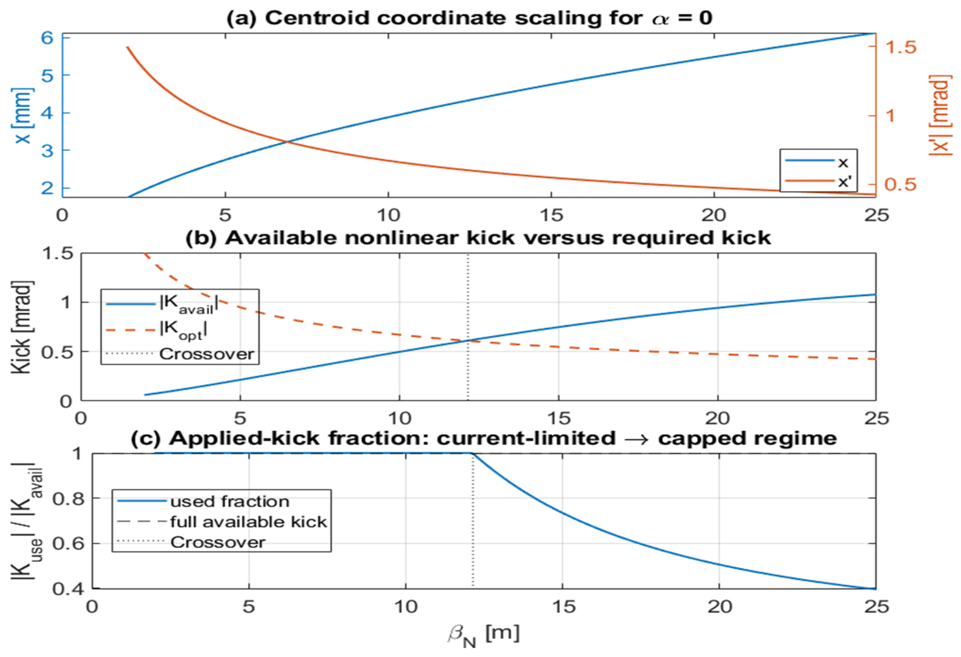
Figure 2 illustrates this scaling using a representative ID2D operating point identified in the baseline hybrid-NLK study [1]. The example assumes , a fixed injected action and phase () chosen to represent the operational first-turn injected trajectory, together with a realistic eight-wire NLK field normalized to provide approximately mrad at mm and an off-axis field peak near mm, consistent with the reference design in Ref. [1]. Under these representative conditions, the available nonlinear kick increases as the injected centroid samples larger transverse offsets, while the required correction kick decreases with increasing . The crossover between these curves marks the transition from a current-limited regime, where the available NLK field is insufficient to provide the ideal correction, to a kick-capped regime, where the available field exceeds the required correction, and only the needed kick is applied.
Figure 2.
Illustrative beta-function scaling and transition from current-limited to kick-capped operation for The calculation is based on the representative ID2D operating point identified in Ref. [1], using a fixed injected action and phase () chosen to represent the operational first-turn injected trajectory, together with a realistic eight-wire NLK field normalized to provide approximately mrad at mm and an off-axis field peak near mm, consistent with the baseline design of Ref. [1]. (a) Centroid offset x and centroid angle x′ as functions of local beta function . Increasing increases the transverse offset sampled by the NLK while reducing the required correction angle. (b) Comparison between the available nonlinear kick , determined by the sampled centroid offset and maximum available NLK strength, and the required correction kick ||. The vertical dashed line marks the illustrative crossover where || = ||. (c) Fraction of available kick applied under the capped-kick strategy. To the left of the crossover, operation is current-limited, and the full available kick is used. To the right, the available field exceeds the required correction, and the applied kick is capped by ||. Because the crossover depends on the representative operating point and NLK design parameters, the figure is intended to illustrate the physical scaling advantage of high- locations rather than provide a universal design boundary.
The exact crossover value depends on the injected action and phase, the NLK field profile, the available current, aperture limits, and hardware constraints. Here, the hardware constraint refers to the maximum available NLK kick , which is set by the chosen wire geometry and field profile together with the maximum peak current deliverable by the pulsed-power system. Consequently, Figure 2 should be interpreted as an illustrative scaling example based on the representative ID2D operating point from Ref. [1], rather than as a universal optimization result. Its purpose is to demonstrate the physical advantage of high- locations—namely, stronger nonlinear-field sampling together with a smaller required correction kick—thereby motivating the more detailed lattice-specific and finite-beam optimization developed in the following sections.
The curves in Figure 2 were generated with in-house MATLAB R2021b scripts by evaluating the Courant–Snyder scaling relations in Section 3.1 and the realistic eight-wire kick profile from the line-current Biot–Savart model described in Ref. [1]. The lattice-dependent transport and tracking calculations used the Accelerator Toolbox [20].
3.2. Ellipse Orientation and Realistic-Field Matching
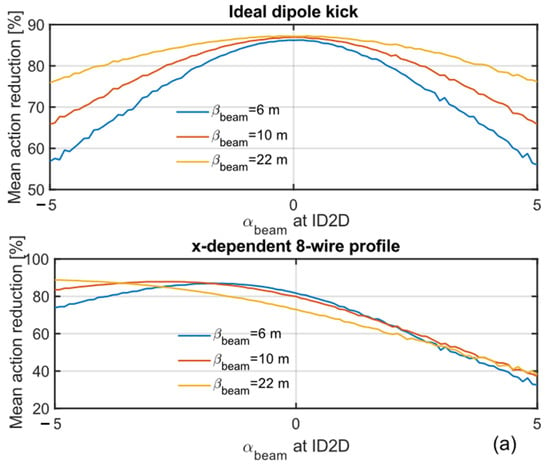
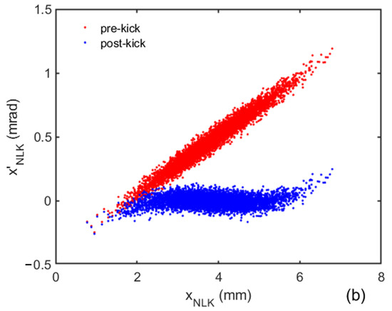
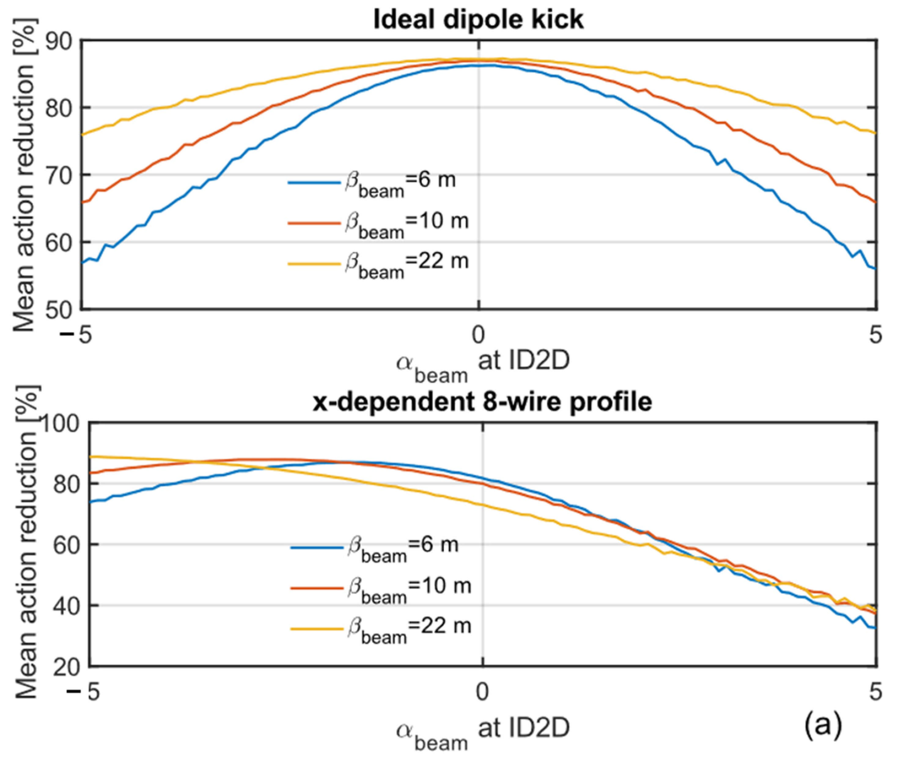
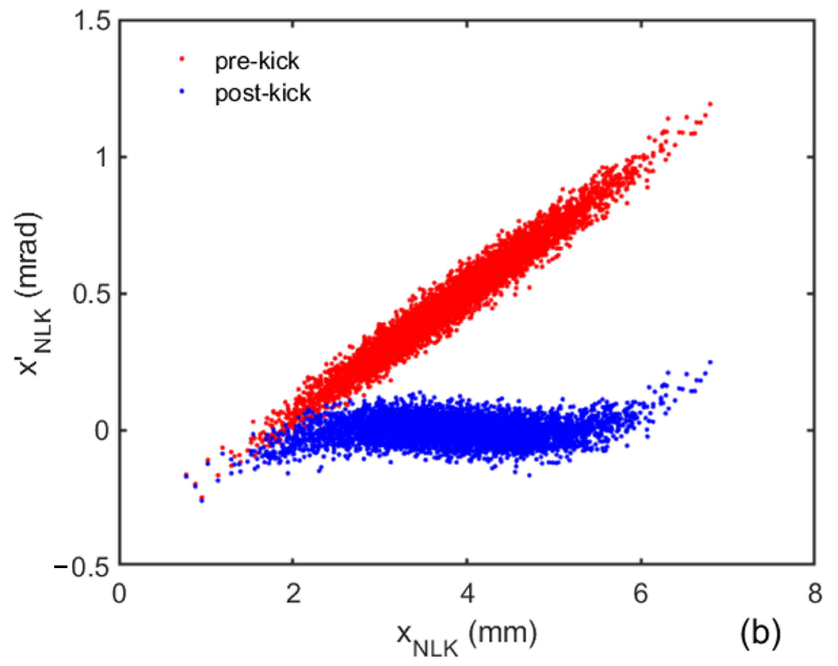
The illustrative ID2D scan in this subsection uses local . More generally, an ideal position-independent kick favors an injected covariance matched to the local storage-ring invariant; for , the matched covariance appears nearly upright in the physical - plane (Figure 3a). The realistic eight-wire NLK instead produces an -dependent kick, so particles across the distribution receive different corrections. For the representative case with m, the strongest action reduction occurs near (Figure 3b), indicating partial matching between the incoming ellipse tilt and the local field slope. This behavior is consistent with the shear-matching condition in Equation (7).
Figure 3.
Representative ID2D scan of injected-beam ellipse orientation using the realistic 8-wire NLK field profile. (a) Comparison of correction performance: an ideal dipole kick favors a near-upright ellipse, whereas the realistic -dependent 8-wire kick favors a tilted ellipse to compensate for phase-space shear. (b) Phase-space distribution of the injected beam before (red) and after (blue) the realistic NLK kick, illustrating the finite-beam shear effect.
For general local optics, the residual centroid contribution after the NLK kick is
Minimization with respect to the post-kick angle gives , equivalently , and therefore . Thus, this residual-position floor is valid for arbitrary local Twiss parameters; at a waist (), the optimum reduces to . Finite-beam optimization should therefore be interpreted as matching the post-kick distribution to the local storage-ring invariant, with the “upright ellipse” description applying only to the special case. The illustrative ID2D examples use , while the covariance formulation and final-action objective remain valid for arbitrary .
This covariance-matching behavior is illustrated in Section 5, where the realistic NLK transforms a tilted incoming ellipse into a nearly floor-limited final-action distribution.
3.3. AC-Septum-Angle Influence at Fixed Beam Covariance
For a fixed ID2D location and fixed transfer-line optics, the AC-septum angle acts as a one-dimensional control knob for the first-turn injected centroid. The resulting centroid coordinates at the NLK can be written as
where and are the transfer-matrix elements from the AC septum to the NLK location. In normalized coordinates,
The influence of AC-septum tuning depends strongly on the relative magnitudes of and . A septum-angle perturbation produces and . Locations near ID1 are characterized by relatively small and large , so AC-septum tuning primarily changes the injected-beam angle and therefore the action-angle phase. In contrast, locations near ID2 have large and small , so AC-septum tuning primarily changes the injected-beam offset while producing only a weak change in injected-beam angle. The AC septum therefore acts mainly as a phase-space steering knob near ID1 and as a field-sampling knob near ID2.
This distinction is particularly important for a realistic NLK because the kick depends strongly on transverse position, . The sensitivity of the sampled kick to AC-septum tuning is approximately , showing that trajectory-controlled field sampling scales directly with . The large values at ID2 allow the injected beam to access substantially different regions of the nonlinear field profile, whereas the smaller values at ID1 provide more limited field-sampling range and rely more strongly on phase-space steering. This explains why ID2D exhibits strong trajectory-controlled optimization through realistic-field sampling, whereas ID1 locations require either narrower operating branches or increased NLK strength.
The AC septum changes both the centroid action-angle coordinates and the region of the nonlinear field sampled by the beam. In linear optics, it does not modify the internal beam covariance, which is determined primarily by transfer-line matching.
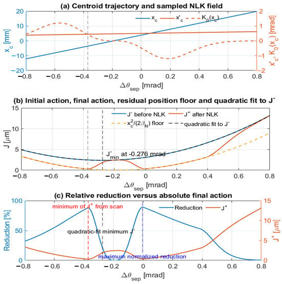
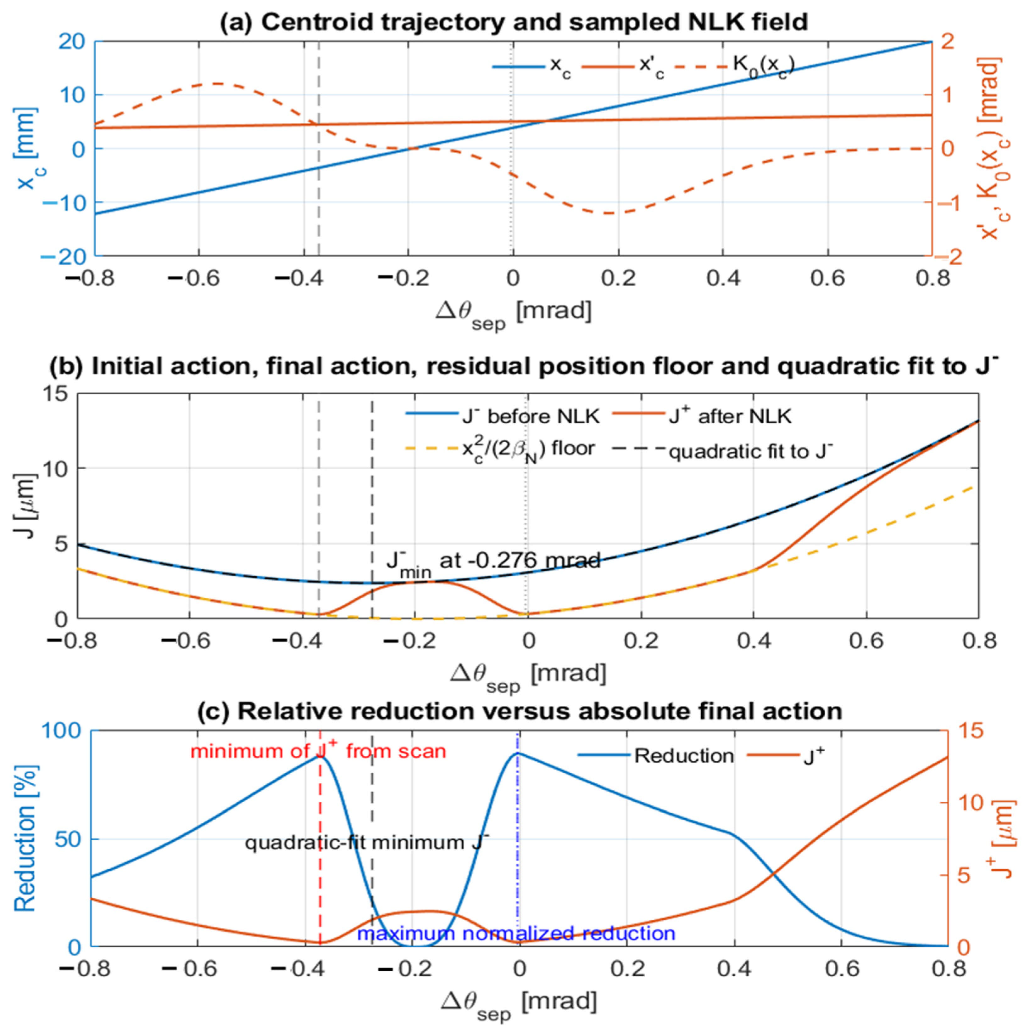
The blue curve in Figure 4b can be understood quantitatively from the linear response of the injected centroid to the AC-septum angle. With the injected position at the septum fixed, changing the septum angle moves the centroid along a one-dimensional line in phase space at the NLK, . Substitution into the Courant–Snyder invariant shows that the incoming centroid action is a quadratic function of septum angle, with a minimum at , where and (. For the ID2D case shown in Figure 4, the quadratic fit predicts the incoming-action minimum near mrad, in good agreement with the minimum of the blue curve.
Figure 4.
Decomposition of AC-septum-angle influence at fixed using the realistic 8-wire NLK field profile. (a) Centroid offset, centroid angle, and sampled NLK kick as functions of AC-septum angle. Septum-angle tuning primarily changes the centroid offset at ID2D, thereby changing the sampled nonlinear field. (b) Initial action, final action, residual position floor, and quadratic fit to the incoming action . The quadratic-fit minimum of occurs near −0.276 mrad, consistent with the analytical expectation that the incoming action is a quadratic function of septum angle. (c) Relative action reduction and absolute final action. The vertical markers show that the minimum incoming action, maximum normalized reduction, and minimum final action occur at different septum settings. This demonstrates why final mean action, rather than percentage reduction alone, is the appropriate optimization metric for realistic NLK operation.
The effect of septum-angle tuning can therefore be understood as a competition between incoming-action growth and improved field sampling. Changing modifies both the incoming action and the sampled offset , thereby moving the beam through different regions of the realistic eight-wire field profile. After the NLK has corrected the angular component, the remaining centroid offset cannot be removed by a single thin kick and contributes a residual Courant–Snyder action approximately
for . This residual-position floor gives the centroid lower-bound contribution to the final action. When the post-kick covariance/shear penalty is small, it provides a simple analytical estimate of the minimum achievable final mean action. Consequently, the septum setting that minimizes the incoming action , the setting that maximizes percentage action reduction, and the setting that minimizes the final action are generally different.
The separation between these optima, evident in Figure 4c, demonstrates that realistic-field sampling rather than minimization of the incoming action alone governs NLK performance at ID2D. More importantly, it shows that the physically relevant optimization objective is the minimization of the final mean action , not the maximization of percentage action reduction. Percentage reduction remains a useful diagnostic of correction efficiency, but it can increase simply because the initial action is larger, even when the residual oscillation after correction is unchanged or increased.
This interpretation also explains why locations that appear unfavorable at the nominal trajectory may become useful once AC-septum tuning is included. A location with large (||/||) can use septum-angle tuning primarily to change the sampled offset while only weakly modifying the injected angle. Thus, the AC septum can move the beam from a weak-field region into a stronger nonlinear-field region while retaining much of the favorable phase-space leverage.
The beta-function dependence provides a complementary interpretation of the ID1 and ID2 behavior. For , a fixed normalized action and phase give and . Therefore, || ≈ || ∝ 1/ and , so the field-sampling leverage available per unit correction kick scales approximately as . The AC septum further enhances this advantage because = , and in many lattices . High-, large- locations therefore provide both stronger field sampling and smaller required correction kick, making the tradeoff between increased incoming action and improved field sampling particularly favorable.
The same scaling also explains why high- locations are advantageous after correction. Although increasing increases the sampled transverse offset and therefore the nonlinear-field leverage, the residual position floor decreases inversely with . High- locations therefore benefit simultaneously from stronger field sampling, smaller required correction kick, and lower residual oscillation after correction. This explains why ID2D is strongly favored, whereas low- ID1 locations require either larger NLK strength or more favorable trajectory-controlled operating branches to achieve comparable final action.
4. Operational Trajectory Leverage and Measured Stability
4.1. Transfer-Matrix Leverage: , , and ||/||
The AC-septum angle provides a finite operational tuning range for controlling the first-turn injected trajectory. For the NSLS-II injection geometry, the nominal AC-septum deflection is approximately 100 mrad. Assuming an adjustable range of ±0.8%, the maximum available trajectory variation is
At a candidate NLK location, the first-order centroid response is determined by and .
For a representative value of m, a ±0.8 mrad tuning range corresponds to approximately ±16 mm of centroid displacement at the NLK. Such a range is sufficient to move the injected beam across substantially different regions of the realistic eight-wire field profile, provided that aperture, septum-clearance, and NLK stay-clear constraints are satisfied.
The same transport coefficient also converts septum power-supply fluctuations into centroid jitter at the NLK. As a design estimate, for a fractional septum stability of and a nominal septum deflection of 100 mrad, the corresponding angular jitter is approximately mrad. For m, this gives a centroid-position jitter of 0.20 mm.
The coefficient therefore plays a dual role. A larger increases the available field-sampling range and enhances the effectiveness of septum-angle tuning, but it also amplifies trajectory jitter arising from septum-power-supply fluctuations. Consequently, an optimal NLK location is not necessarily the location with the largest , but rather one that provides sufficient trajectory leverage to access favorable field-sampling regions while maintaining acceptable aperture margin and operational stability.
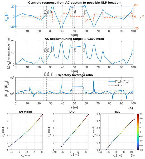
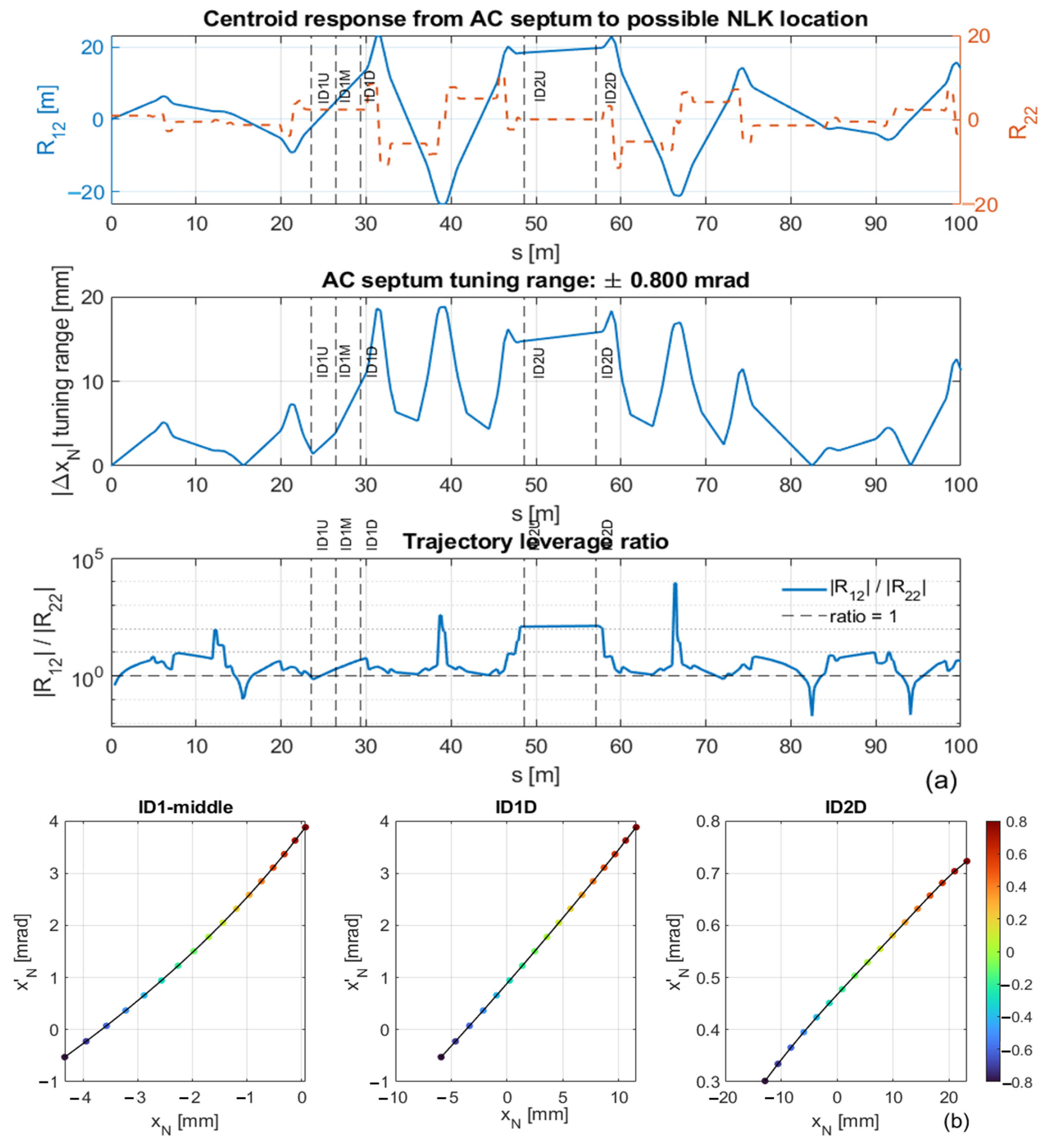
Figure 5a illustrates this tradeoff. The upper panel shows the transfer-matrix coefficients and from the AC septum to potential NLK locations. The middle panel shows the corresponding centroid tuning range for the available septum-angle variation. The bottom panel shows the trajectory-leverage ratio ||/||, which highlights the transition from phase-steering-dominated locations near ID1 to field-sampling-dominated locations near ID2. This distinction explains why ID2 locations exhibit strong trajectory-controlled optimization through realistic-field sampling, whereas ID1 locations rely more strongly on phase-space steering and therefore require either narrower operating branches or increased NLK strength.
Figure 5.
Septum-angle controllability and phase-space trajectory leverage. (a) Transfer-matrix response from the AC septum to possible NLK locations. The top panel shows (blue) and (orange), the middle panel shows the centroid tuning range for a mrad septum-angle range, and the bottom panel shows the trajectory-leverage ratio . Candidate NLK locations are marked by dashed vertical lines. (b) AC-septum-driven centroid trajectories in horizontal phase space for ID1-middle, ID1D, and ID2D. The ID1 locations show stronger angular variation, whereas ID2D shows a much larger horizontal offset sweep with comparatively small angular change, confirming that AC-septum tuning acts primarily as a field-sampling knob at ID2D.
The same distinction is visualized in the horizontal phase space (Figure 5b). When the AC-septum angle is scanned, the centroid at ID1-middle and ID1D locations follows a trajectory with substantial angular variation, indicating dominant phase-space steering. In contrast, at ID2D, the trajectory is significantly flatter: the horizontal offset changes by several tens of millimeters while the angular variation remains comparatively small. This behavior is consistent with the large ratio at ID2D, confirming that AC-septum tuning at this location primarily controls field sampling rather than the injected beam angle.
4.2. Operational Validation of Trajectory Control
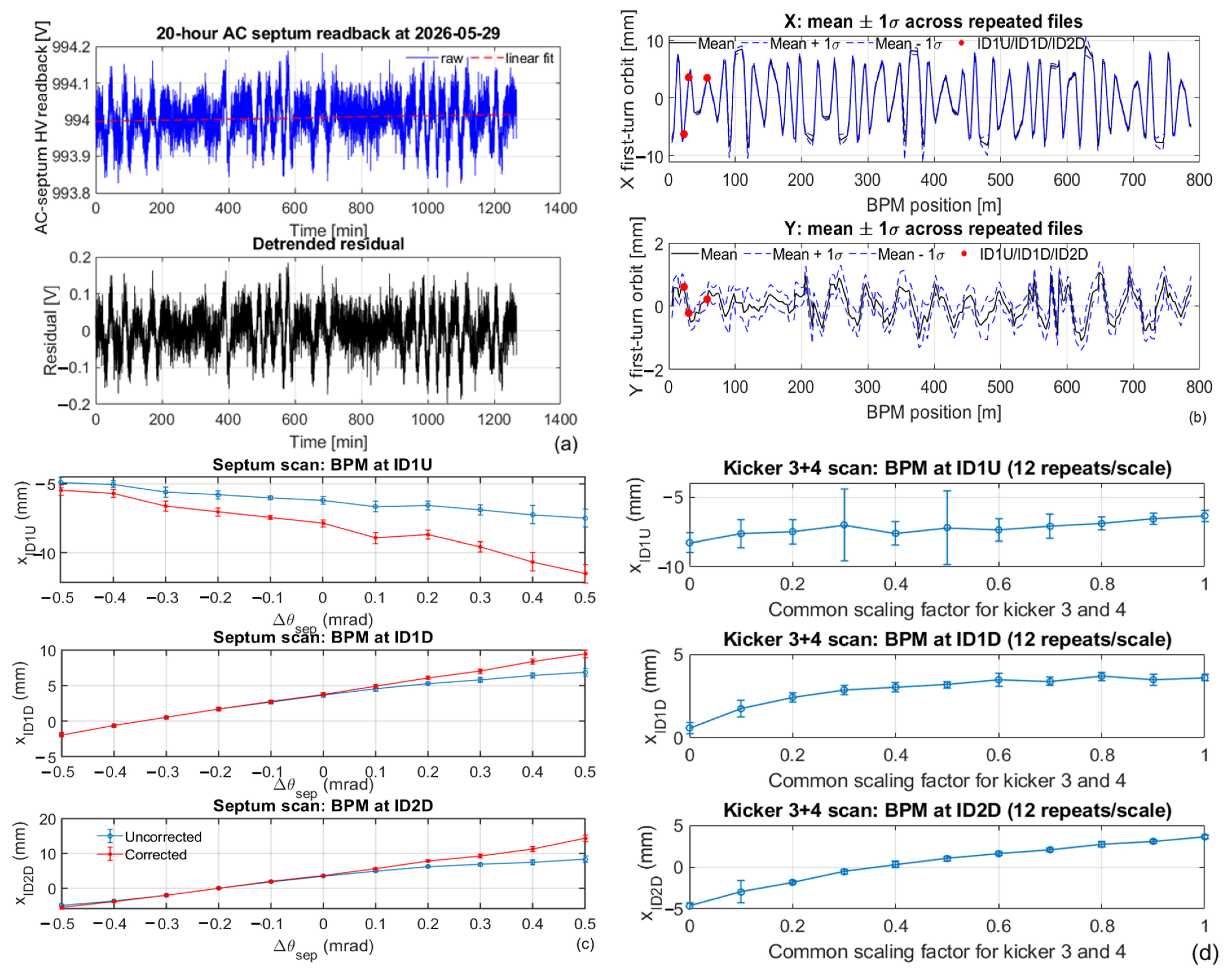
The preceding sections establish that realistic NLK performance depends sensitively on the first-turn injected trajectory. A practical implementation therefore requires not only a favorable modeled operating point, but also sufficient operational control and reproducibility of the injected trajectory. To test these requirements, three measurements were performed: first-turn trajectory stability, AC-septum response over a ±0.5% scan, and injection-bump response using bump 3 and bump 4. Together with the 20-h AC-septum readback analysis, these measurements provide direct validation of the trajectory-control assumptions used in the optimization framework.
4.2.1. AC-Septum Stability
Figure 6a shows the calibrated AC-septum high-voltage power-supply readback in volts. The readback is linear with the setpoint and is converted through the established calibration to the corresponding peak current and kick. It is a slow-control readback rather than a pulse-resolved current measurement because the present control system does not archive the current waveform or peak-current value. After removal of a linear drift, the residual rms fluctuation was 0.0563 V on a mean signal of 994.005 V, corresponding to a relative stability of . Based on the calibrated linear readback-to-kick relation, the equivalent angular rms is 0.0057 ± 0.0011 mrad for the nominal 100 mrad deflection, where the uncertainty is the block-to-block standard deviation from 20 contiguous one-hour blocks. This value characterizes short-term stability inferred from the high-voltage readback, not a direct pulse-to-pulse magnetic-field measurement. The repeated first-turn trajectories in Figure 6b provide an independent end-to-end measure of operational reproducibility, while the trajectory response in Figure 6c readily resolves septum-kick changes of approximately 0.05 mrad (half the scan step), corresponding to a relative scale of . For m, the inferred short-term angular fluctuation corresponds to approximately 0.11 mm rms centroid motion at the NLK, with an observed peak-to-peak variation of approximately 0.80 mm. These values are substantially smaller than the available trajectory-control range and efficient field-sampling windows, indicating that short-term AC-septum stability is unlikely to be the dominant limitation.
The fitted relative drift rate is ( of the nominal AC-septum signal, where 0.14 is the standard error of the linear-fit slope. For a 100 mrad nominal kick, this corresponds to an angular drift of approximately (0.09 mrad per hour, or an injected-centroid drift at the NLK of approximately (1.8 mm per hour for m. Consequently, AC-septum stability naturally separates into two operational requirements. Short-term jitter determines trajectory reproducibility from injection to injection, whereas slow drift determines how long the injected beam remains within an efficient NLK field-sampling region.
Viewed in this way, the AC septum functions not only as a trajectory-control knob but also as a field-sampling control knob. The measured short-term stability is sufficient to maintain reproducible sampling of the realistic eight-wire field profile, while the observed slow drift is gradual enough to be managed through periodic trajectory steering or a slow feedback loop. These measurements confirm the practical feasibility of trajectory-controlled NLK optimization, provided that slow centroid drifts are routinely compensated during standard operation.
4.2.2. First-Turn Trajectory Stability
The first-turn trajectory stability measurement tests whether the injected centroid remains within the field-sampling window required for efficient NLK operation. Figure 6b and Table 1 show the mean first-turn horizontal and vertical trajectories and corresponding ±1σ variations from 120 consecutive injections acquired at 1/3 Hz. Three BPM rows, associated with the ID1U, ID1D, and ID2D regions used in the trajectory-control study, are highlighted.
Table 1.
First-turn trajectory stability at representative BPM locations corresponding to candidate NLK regions. Mean centroid position and rms trajectory fluctuation measured over repeated injections at BPMs nearest to ID1U, ID1D, and ID2D. The observed shot-to-shot variations remain below 0.4 mm in both planes, indicating that first-turn trajectory reproducibility is sufficient for trajectory-controlled NLK field sampling.
The measured horizontal rms jitter at the highlighted BPM rows is approximately 0.32–0.36 mm, while the vertical rms jitter is approximately 0.30–0.32 mm. These values are small compared with the multi-millimeter trajectory-control range available from the AC septum and the high-efficiency field-sampling windows identified in the scans. Thus, shot-to-shot first-turn trajectory reproducibility is not expected to be the dominant limitation for NLK operation, although slow centroid drift should still be corrected operationally. At ID2D, the measured horizontal rms variation is 0.316 mm. With m, the direct position contribution is only about 0.6% of the representative optimized final mean action of . For an NLK optimized for the nominal centroid, trajectory jitter also changes the sampled kick, to first order, according to ; the additional degradation therefore depends on the local field slope and is naturally reduced near a field extremum, where . The measured position jitter is therefore small compared with the optimized action scale, while a complete quantitative estimate requires the measured jitter and – covariance.
First-turn trajectories were measured with the standard NSLS-II button-type RF BPM system using injection-synchronized turn-by-turn acquisition. To isolate the injected-beam signal from the stored beam, kicker 1 was intentionally delayed by one revolution, causing the injected beam to be lost within the injection region, where adequate shielding is provided. This timing configuration prevents accumulation of the injected beam and enables the measured first-turn BPM signal to be attributed solely to the injected bunch. The large-offset readbacks used in the septum scan were evaluated both before and after applying the established BPM polynomial calibration [21,22,23].
Slow drift of the injected trajectory can be monitored using an injection-synchronized BPM immediately downstream of the septum. The mechanical center of this BPM is horizontally offset by approximately 15 mm toward the injected-beam trajectory, making its first-turn signal predominantly sensitive to the injected beam rather than the stored beam. Using the same trigger as the BTS single-pass trajectory acquisition, this BPM therefore provides a practical monitor of slow septum-induced trajectory drift. The measured drift can be compensated through periodic or slow adjustment of the AC-septum setting, while the standard orbit-feedback system independently maintains the stored-beam closed orbit.
4.2.3. Measured AC-Septum Response
The measured AC-septum response provides an experimental calibration of the trajectory-control vector used in the optimization model as shown in Figure 6c. This approach is conceptually similar to orbit-response-based optics measurements commonly used for storage-ring characterization and correction [24,25]. A ±0.5% change in AC-septum setting corresponds to approximately ±0.5 mrad for a 100 mrad nominal septum deflection. The horizontal response is approximately linear over this range and directly measures the effective position-leverage coefficient from the septum to the selected BPM rows. For each BPM, was obtained from a linear fit of horizontal position versus AC-septum angle. The statistical uncertainty in was taken as the standard error of the fitted slope, calculated from the residual variance of the linear regression.
The measured horizontal slopes preserve the expected hierarchy of trajectory leverage: ID2D exhibits the largest response, ID1D is intermediate, and ID1U has a negative response. Because the injected beam samples relatively large horizontal offsets in this scan, the measured response was evaluated both before and after applying the BPM polynomial calibration [13,14,15]. This correction accounts for BPM nonlinearity at large offsets and substantially improves the quantitative agreement with the transport model at the optics-favored ID2D location, where the measured response changes from 13.9 to 19.4 mm/mrad, in excellent agreement with the modeled value of 19.8 mm/mrad (Table 2). At the ID1 locations, the corrected results preserve the expected sign and trajectory-leverage hierarchy and remain reasonably consistent with the model. These results validate the AC septum as a predictable and quantitatively calibrated field-sampling control knob for realistic NLK optimization.
Table 2.
Comparison of modeled and measured AC-septum trajectory response. Measured values were obtained from first-turn trajectory scans over the approximately linear response region between −0.5% and +0.5% AC-septum variation. The measured coefficients are shown before and after applying the BPM polynomial calibration [21,22,23]. The polynomial correction substantially improves agreement with the beam-dynamics model, particularly at the optics-favored ID2D location, while preserving the expected trajectory-leverage hierarchy. These results confirm that the AC septum provides a predictable and quantitatively calibrated field-sampling control knob for realistic NLK optimization.
Importantly, no measurable injection-efficiency degradation was observed within the tested AC-septum scan range, supporting the use of septum-angle tuning as a practical trajectory-control knob for NLK optimization.
Figure 6.
Operational validation of trajectory control. (a) Twenty-hour AC-septum stability measurement. (b) First-turn trajectory stability from repeated injections, shown using raw BPM readbacks to quantify shot-to-shot reproducibility. (c) Measured first-turn horizontal trajectory response to a ±0.5% AC-septum scan at representative BPM locations near ID1U, ID1D, and ID2D; blue and red markers indicate uncorrected and BPM-polynomial-corrected readbacks, respectively. The response coefficients reported in Table 2 are obtained from the same scan before and after applying the BPM polynomial calibration. (d) Measured horizontal trajectory response to common scaling of injection bump 3 and bump 4, shown as an operational steering demonstration. The measurements demonstrate sub-millimeter first-turn reproducibility, predictable AC-septum trajectory leverage, and additional trajectory-control authority from the injection bumps.
4.2.4. Bump 3 and Bump 4 Scans
The bump 3 and bump 4 response scans test whether additional injection knobs can correct slow drift or fine-tune the first-turn trajectory without relying solely on the AC-septum angle. In this measurement, the injection bumps (bump 3 and bump 4) were varied using a common scaling factor, and the first-turn trajectory response was measured at the same representative BPM rows.
The horizontal response shows several millimeters of controllable motion, particularly at the ID1D and ID2D representative BPM rows, as shown in Figure 6d. The response demonstrates that the injection bumps provide an additional degree of freedom for horizontal trajectory control that can be used to compensate for slow trajectory drift or steer the injected beam toward a desired field-sampling region. In combination with AC-septum tuning, bump 3 and bump 4 therefore provide practical operational knobs for maintaining the injected beam near an optimized NLK operating branch.
The AC septum remains the primary trajectory-control knob for NLK optimization. Bump 3 and bump 4 provide additional horizontal steering authority and may serve as backup knobs for correcting residual trajectory errors or slow drift. In principle, their response can contain both position- and angle-like components at the NLK. However, their usable variation is constrained by the requirement to maintain closure of the four-kicker stored-beam bump; mismatch of bump 3 and bump 4 would perturb the stored-beam orbit and is therefore undesirable. Accordingly, the present common-scaling measurement is used only to demonstrate available backup steering authority, rather than as an additional independent optimization degree of freedom.
The operational measurements support the principal assumptions of the trajectory-control framework. First-turn jitter remains sub-millimeter at the selected BPM rows, the AC-septum response agrees well with the modeled trajectory leverage in the linear operating region, and bump 3/4 scaling provides an additional horizontal steering direction. Together, these results indicate that the NSLS-II storage ring provides sufficient trajectory-control authority to access and maintain the modeled NLK operating branches.
5. Combined Optimization at Fixed ID2D
The AC septum and transfer-line optics provide complementary control knobs. The AC septum primarily controls the centroid trajectory at ID2D, whereas transfer-line matching controls the beam covariance and ellipse orientation. A fixed-ID2D optimization should therefore treat the final NLK performance as a combined centroid-matching and ellipse-matching problem:
For a fixed ID2D location, the proposed optimization variables are
The objective should be the final mean action, rather than only percentage reduction, because changing the septum angle or transfer-line match can also change the initial action:
The realistic NLK is represented by the position-dependent kick map
Here is the normalized position-dependent kick profile of the realistic eight-wire NLK, expressed as kick per unit NLK-current scaling, and sets the overall kick amplitude.
The optimization objective is the mean post-kick Courant–Snyder action of the injected beam,
Here the angle brackets denote the average over the injected particle distribution. For interpretation, the final mean action can be decomposed into a centroid contribution and a finite-beam spread contribution,
Unlike percentage action reduction, directly quantifies the residual oscillation after the realistic NLK kick and therefore provides a physically meaningful objective for comparing operating points with different initial actions, beam covariances, and field-sampling conditions. This formulation naturally separates the roles of the two optimization knobs: the AC septum primarily controls the centroid trajectory and field sampling, whereas transfer-line matching controls the injected covariance. A favorable septum setting may place the centroid in a strong-field region, but optimal performance still requires the beam ellipse to be matched to the local field slope and curvature.
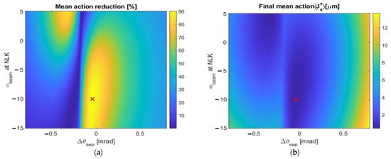
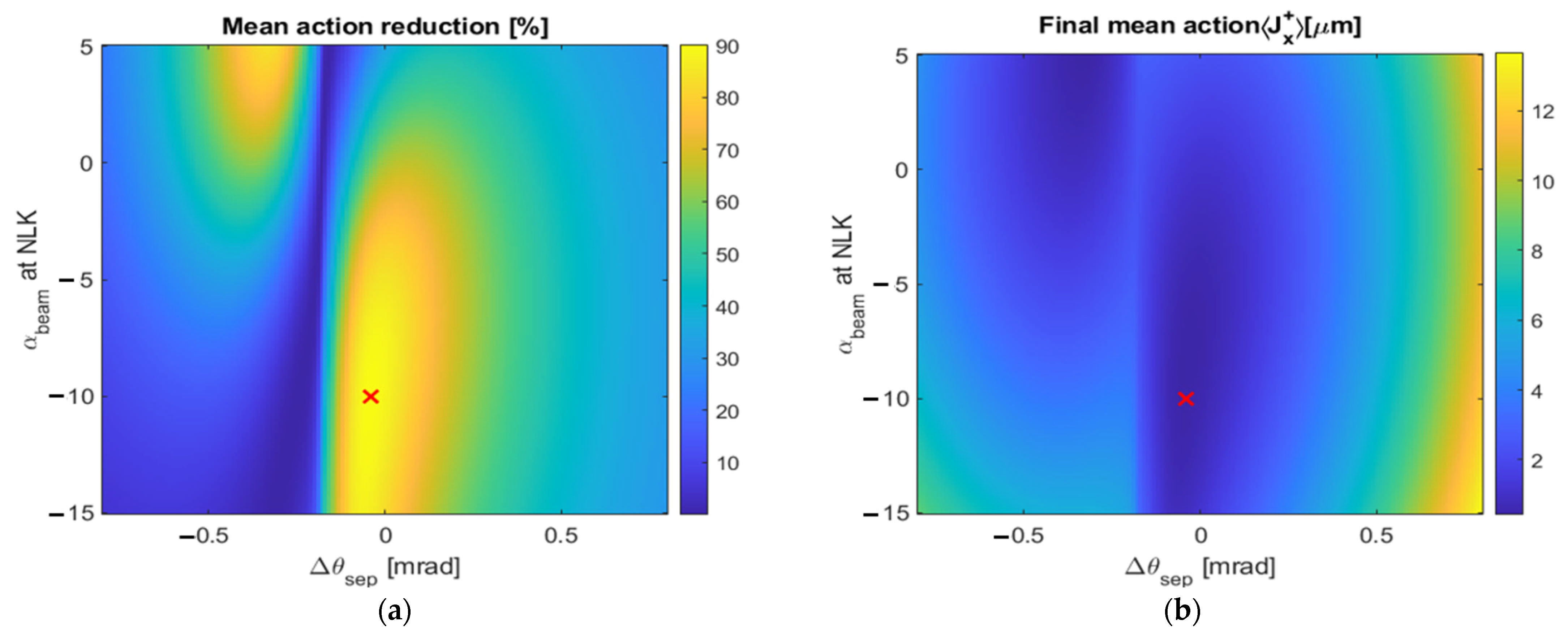
Figure 7a shows the combined optimization scan involving AC-septum trajectory control and transfer-line matching at ID2D. The action-reduction landscape exhibits stronger variation along the septum-angle axis than along the axis, indicating that realistic-field sampling is the dominant first-order mechanism. The favorable region lies toward negative , suggesting that practical transfer-line constraints may ultimately limit the achievable covariance match. Figure 7b shows the final mean action . In contrast to the reduction map, the final-action landscape is comparatively weakly dependent on . This difference highlights the importance of distinguishing between relative improvement and absolute performance: more negative can increase the percentage reduction partly by increasing the initial action , even when changes only modestly. The present scan should therefore be interpreted as a reduced-parameter demonstration; a full commissioning implementation would use covariance matrices obtained directly from measured or modeled transfer-line optics scans.
Figure 7.
Combined AC-septum and transfer-line optimization landscape at ID2D. (a) Mean horizontal action reduction as a function of AC-septum angle and injected-beam ellipse parameter . (b) Final mean action over the same grid. The final-action map is the primary optimization objective, while the reduction map shows relative improvement. The comparison indicates that field sampling through AC-septum trajectory control dominates, while transfer-line matching acts as a secondary covariance-matching knob. The red marker indicates a representative operating point within the optimization scan.
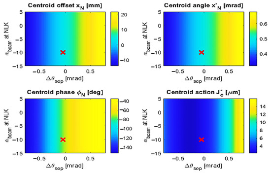
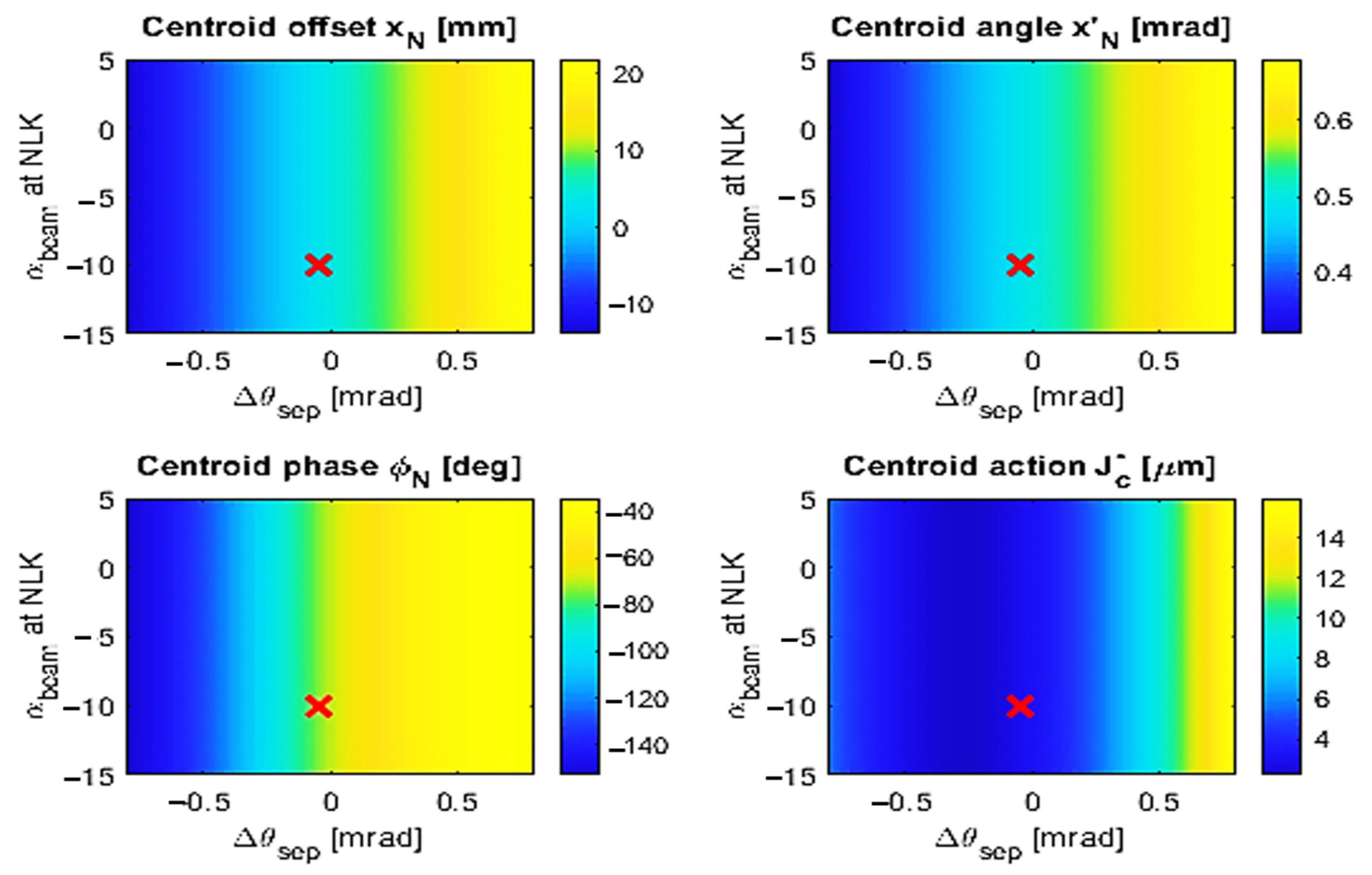
To separate centroid-trajectory effects from covariance effects, Figure 8 shows the centroid offset, centroid angle, normalized phase, and centroid action over the same parameter grid. These quantities vary primarily with septum angle and are nearly independent of , confirming that in this scan the AC septum controls the centroid trajectory and action-angle phase, whereas mainly modifies the injected covariance. The residual dependence in Figure 7b therefore reflects finite-beam ellipse matching to the local NLK field slope and curvature, rather than a change of centroid trajectory.
Figure 8.
Centroid trajectory and action-angle diagnostics for the ID2D combined scan. The nearly vertical structure of , , , and indicates that these centroid quantities are controlled primarily by AC-septum angle and are nearly independent of . Here . The red marker indicates a representative operating point within the optimization scan.
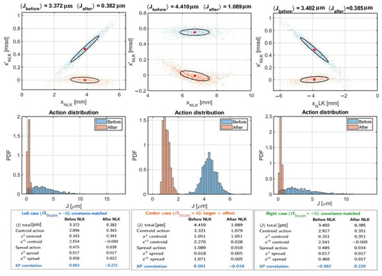
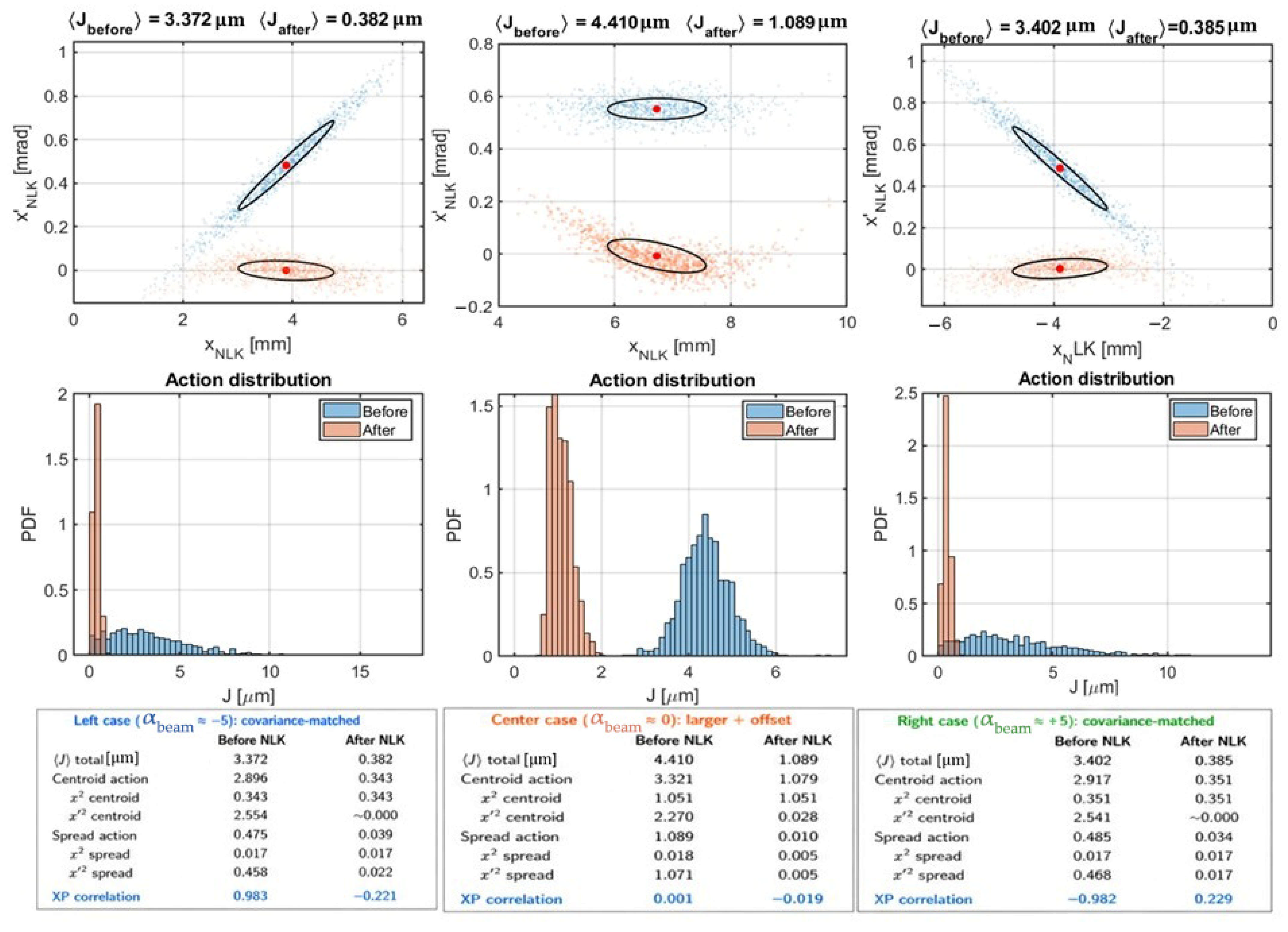
To illustrate the physical mechanisms underlying the optimization maps, Figure 9 compares three representative ID2D operating conditions selected from distinct operating branches rather than along a local path through adjacent grid points. The three cases isolate the coupled effects of centroid field sampling, incoming covariance, and residual action: covariance-matched correction on one field-sampling branch, stronger-field sampling at a larger residual offset, and covariance-matched correction on the opposite branch. The left case uses a negatively tilted incoming beam ellipse, , chosen to approximately match the local slope of the realistic NLK field. In this case, the NLK not only removes the centroid-angle mismatch but also compensates for the incoming finite-beam phase-space tilt, producing the lowest final mean action among the three examples. The center case samples a stronger-field region at a larger positive offset and gives a large fractional reduction, but its larger remaining centroid offset leads to a higher final mean action. The right case provides the corresponding covariance-matched solution on the opposite side of the nonlinear field profile, demonstrating that both field-sampling branches can approach the same residual-position floor when the incoming beam covariance is properly matched to the local field slope.
Figure 9.
Illustrative phase-space transformations explaining realistic NLK optimization (ID2-downstream). The upper row shows particle phase-space distributions before (blue) and after (orange) application of the NLK, together with the corresponding covariance ellipses and centroids. The lower row shows the associated action distributions, and the boxes summarize action decompositions (in ). Left: covariance-matched case with at . Center: larger positive-offset case with at . Right: covariance-matched case with at . When the incoming ellipse tilt matches the local NLK field slope (left and right), the NLK compensates the finite-beam shear, reducing both the centroid-angle mismatch and the angular-spread contribution. In contrast, the larger residual centroid offset in the center case results in a higher floor-limited final action.
The left case provides a direct numerical demonstration of the shear-matching condition in Equation (7). Before the kick, the mean action is , with a substantial finite-beam spread contribution of 0.475 . After the realistic NLK kick, the centroid-angle contribution is nearly eliminated, and the centroid action becomes 0.343 , equal to the residual-position floor . The finite-beam spread contribution is simultaneously reduced from 0.475 to 0.039 , mainly through reduction of the angular-spread term from 0.458 to 0.022 . This confirms that, when the incoming ellipse tilt is matched to the local NLK field slope, the realistic nonlinear kick can compensate for the finite-beam shear instead of increasing it.
The center case provides a complementary validation of the residual-position-floor interpretation developed in Section 3.3. Using the optimized centroid offset ( = 6.81 mm) and the local beta function ( = 22 m), Equation (10) gives ) , in close agreement with the particle-tracking result of = 1.089 . This agreement shows that, when the post-kick covariance penalty is small, the remaining centroid offset sets the dominant lower bound on the achievable final action.
This comparison highlights the distinction between normalized action reduction and absolute final action. A large percentage reduction may reflect efficient correction of a large initial mismatch, but the relevant optimization objective is the minimization of the final mean action , including both the centroid residual and the finite-beam covariance response.
6. Candidate NLK Operating Branches and Fallback Locations
The preceding sections establish the physical and measured trajectory-control mechanisms. We now compare candidate operating branches in terms of achievable final action, required NLK strength, trajectory-control authority, and practical integration. Table 3 summarizes representative optimized branches for ID2D, ID1-middle, and ID1D. ID2D provides the lowest residual action with comparatively modest NLK strength. ID1-middle provides an intermediate-strength solution but operates near the AC-septum setting at which beam loss begins to occur, limiting its practical operating margin. ID1D provides a broader trajectory-controlled branch but requires approximately four times the baseline NLK strength.
Table 3.
Comparison of representative optimized NLK operating branches.
6.1. ID1-Middle Trajectory-Controlled Branch
Although ID2D remains the optics-favored solution, the ID1 studies demonstrate that efficient operating branches can also be accessed through trajectory control. Compared with ID2D, the ID1 locations possess smaller and larger , so AC-septum tuning acts primarily as a phase-space steering knob rather than a field-sampling knob. Consequently, their performance depends more strongly on identifying favorable operating branches within the accessible trajectory range.
For ID1-middle, the available AC-septum tuning range is sufficient to move the injected centroid into a favorable region of the realistic eight-wire field profile (Figure 5b). Although the available field-sampling range is more limited than at ID2D, the finite injected beam still samples a distribution of nonlinear kick strengths across the field profile. The observed action reduction therefore arises from the combined effects of centroid placement and finite-beam field sampling rather than from centroid correction alone.
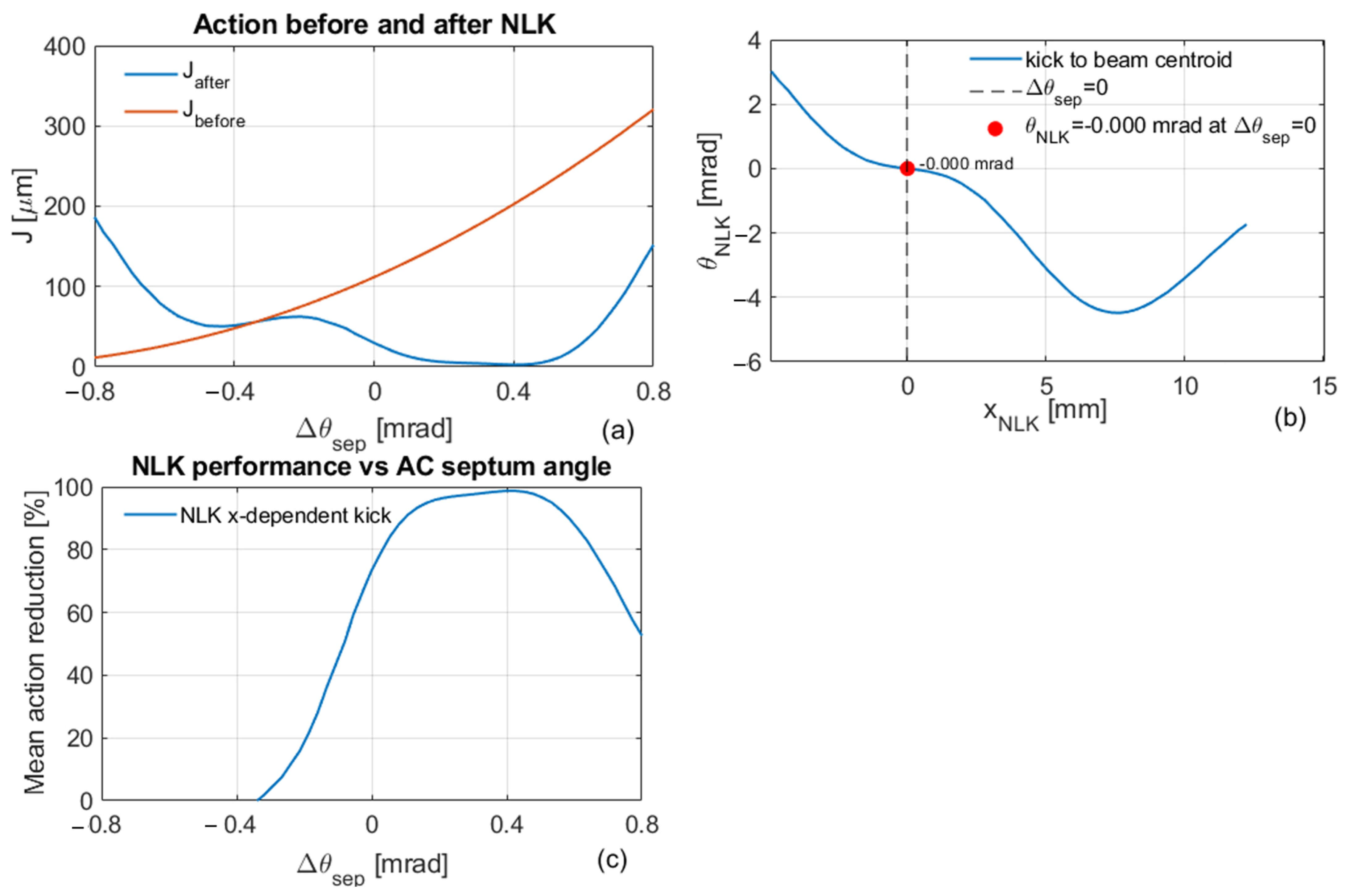
Auxiliary ID1-middle scans indicate that a compact trajectory-controlled branch can be reached within the available AC-septum tuning range. Because this branch is narrower and more sensitive to the assumed trajectory and field-sampling conditions than the ID1D case, the ID1D branch in Figure 10 is used as the representative trajectory-controlled fallback example.
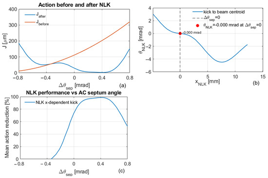
Figure 10.
ID1D trajectory-controlled operating branch with increased NLK strength. With a fourfold increase in kicker strength, AC-septum tuning moves the injected beam across a substantially broader region of the realistic nonlinear field profile, producing a wide high-efficiency operating branch. Compared with ID2D, the ID1D solution requires significantly higher NLK strength but demonstrates that trajectory control can partially compensate for less favorable nominal optics. All scans use mrad. (a) Mean action before (orange) and after (blue) the NLK kick as a function of . (b) Sampled NLK kick as a function of injected-beam offset ; the red marker denotes the nominal septum setting ( = 0). (c) Mean action reduction as a function of AC-septum angle.
6.2. ID1D Trajectory-Controlled Branch
A similar study at ID1D shows that efficient injection can also be achieved when additional NLK strength is available. With a fourfold increase in kicker strength, AC-septum tuning moves the injected centroid from approximately −5 mm to +12 mm, allowing the beam to access a substantially broader region of the realistic field profile.
The final action is strongly reduced over a wide range of positive septum-angle offsets, with the optimum occurring near ≈ 0.3–0.5 mrad. Compared with ID2D, this solution is more demanding from a hardware perspective because it requires significantly higher NLK strength. Nevertheless, the broad high-efficiency branch demonstrates that trajectory control can partially compensate for less favorable nominal optics by steering the beam into advantageous field-sampling regions.
These results reinforce the central conclusion of this work: favorable NLK performance is determined not solely by the local optics, but by the combined effects of trajectory-control authority, realistic field sampling, finite-beam covariance, and available NLK strength. Consequently, ID1D represents a practical fallback solution when installation, aperture, or integration constraints limit implementation at ID2D.
7. Discussion and Conclusions
The candidate-location comparison highlights the tradeoff between beam-dynamics performance and practical integration. ID2D is the preferred beam-dynamics solution because its high and large provide strong field-sampling leverage and lower required NLK strength. However, installation in an insertion-device straight may compete with present or future insertion devices and impose additional integration constraints. It is therefore important to retain alternative NLK locations while, where practical, keeping the kicker sufficiently close to the injection point to suppress the injected-beam oscillation early in the first turn. ID1-middle provides an accessible trajectory-steered alternative but with a narrower operating window, whereas ID1D offers a broader fallback branch at the cost of approximately four times the NLK strength. These alternatives demonstrate that practical NLK design should optimize location, trajectory-control authority, field sampling, hardware requirements, and integration constraints together rather than select a location from optics alone. Although the quantitative tradeoffs are specific to NSLS-II, the underlying framework—minimization of final mean action through coupled centroid control, covariance matching, and realistic field sampling—is applicable to other NLK-based injection systems.
The results show that realistic NLK optimization is not a centroid-only correction problem. The final performance is determined by the combined dependence on centroid action-angle coordinates, injected-beam covariance, local eight-wire field slope and curvature, trajectory-control range, and available NLK current and polarity. The AC septum provides the primary knob for controlling centroid field sampling, while transfer-line matching controls the finite-beam covariance and ellipse orientation. This separation of centroid trajectory control and covariance control is the central conceptual advance over conventional centroid-only NLK optimization. NLK current and polarity then determine which correction branch is selected and whether the sampled field can provide the required kick. Accordingly, realistic NLK optimization must treat covariance matching and nonlinear field sampling as coupled design variables.
Changing alters the incoming centroid coordinates and hence the centroid action, whereas changing modifies the covariance and finite-beam mismatch. Percentage action reduction therefore conflates the initial mismatch with the residual oscillation: a larger initial action can yield a larger percentage reduction even when the absolute post-kick mean action is unchanged or higher. Across the three representative ID2D cases in Figure 9, the initial mean action varies from 3.372 to 4.410 μm (approximately 31%), while the final mean action ranges from 0.382 to 1.089 μm, corresponding to reductions of approximately 75–89%. Percentage reduction remains a useful diagnostic but is not a sufficient optimization metric; final mean action is the primary objective. Figure 4, Figure 7 and Figure 9 illustrate this distinction.
The resulting framework separates trajectory optimization, covariance matching, and current optimization into distinct but coupled control knobs. The AC septum determines where the injected beam samples the nonlinear field, transfer-line matching determines how the finite beam responds to the local field gradient and curvature, and the NLK current and polarity determine the attainable correction branch. This separation provides a practical basis for realistic NLK commissioning and establishes a direct connection between operational trajectory control and finite-beam optimization.
An important consequence of this framework is that the optimal NLK operating point is determined jointly by trajectory control and covariance matching. A favorable trajectory alone does not guarantee optimal performance if the injected beam covariance is poorly matched to the local field gradient, and conversely, an optimal covariance cannot compensate for unfavorable field sampling. Realistic NLK optimization therefore requires simultaneous consideration of centroid coordinates, beam covariance, field profile, and operational control authority.
If horizontal correctors near the end of the transfer line are used to vary the injected-beam position and angle at the septum exit, the resulting NLK response can be written as
The AC septum provides predominantly angle-like control through , , whereas a suitably configured corrector pair can introduce an additional position-like component involving , . If these response vectors are sufficiently non-collinear, their combination can provide more independent control of and , potentially improving trajectory optimization at locations with weaker AC-septum leverage, such as the ID1 alternatives. Practical limits include septum clearance, transfer-line aperture, available corrector strength, and reproducibility. A measured multi-knob response-matrix optimization is therefore a natural extension of the present work.
The present formulation uses linear transport and uncoupled horizontal Courant–Snyder action as the principal diagnostic. In a strongly nonlinear storage-ring region, sextupole and higher-order terms can distort the invariant at injection amplitudes, so the transport to the NLK and the post-kick objective should be generalized using nonlinear tracking or a numerically determined invariant. Finite transverse coupling would likewise require extension from a 2 × 2 horizontal covariance to the coupled 4D transverse covariance and corresponding normal-mode actions. These extensions do not change the central optimization principle—joint control of centroid field sampling and finite-beam phase-space matching—but they modify the appropriate transport map and objective function.
In conclusion, a covariance-aware framework has been developed for hybrid NLK injection using a realistic eight-wire kick profile. The analysis shows that the NLK modifies both the injected-beam centroid and the internal phase-space ellipse. The AC-septum angle controls the first-turn centroid trajectory and field sampling, while transfer-line matching controls the injected covariance. This separation provides a practical basis for optimizing , , and simultaneously.
Application of the framework to NSLS-II candidate locations identifies ID2D as the preferred optics-favored solution, while ID1-middle and ID1D remain viable trajectory-controlled alternatives under different hardware constraints. Operational measurements confirm that the required trajectory-control authority exists in the machine, supporting the practical feasibility of covariance-aware NLK optimization. These results provide a practical path toward NLK commissioning based on measured trajectory-control authority, realistic field sampling, and final-action minimization. More broadly, these results establish covariance-aware field-sampling optimization as a general framework for realistic nonlinear-kicker injection and provide an experimentally validated methodology for future diffraction-limited storage rings employing nonlinear-kicker injection.
Funding
This work was supported by Brookhaven National Laboratory Directed Research and Development Program. This manuscript has been authored by Brookhaven Science Associates under Contract No. DE-SC0012704 with the U.S. Department of Energy and Brookhaven National Laboratory LDRD 27721. The United States Government retains, and the publisher, by accepting the article for publication, acknowledges that the United States Government retains a non-exclusive, paid-up, irrevocable, worldwide license to publish or reproduce the published form of this manuscript, or allow others to do so, for United States Government purposes.
Data Availability Statement
The datasets generated and analyzed during the current study are available from the corresponding author upon reasonable request.
Acknowledgments
The author is grateful to V. Smaluk, J. Lee, and J. Choi for valuable discussions and technical assistance. Special thanks are extended to T. Shaftan for exceptionally valuable discussions, guidance, and continued support throughout the NLK injection project.
Conflicts of Interest
The author declares no competing financial or non-financial interests in relation to the work described in this paper.
References
- Yang, X.; N’Gotta, P. A Unified Beam-Dynamics and Hardware Design Framework for Hybrid Nonlinear-Kicker Injection in NSLS-II. Instruments 2026, 10, 34. [Google Scholar] [CrossRef] [Scilit]
- Gora, A.; Abo-Bakr, M.; Dirsat, M.; Rehm, G.; Ries, M. Beam-based characterization of a non-linear injection kicker at BESSY II. In Proceedings of the 14th International Particle Accelerator Conference (IPAC2023), Venice, Italy, 7–12 May 2023. MOPM075. [Google Scholar] [CrossRef]
- Liu, L.; Resende, X.; Rodrigues, A.; de Sá, F. Injection Dynamics for Sirius Using a Nonlinear Kicker. In Proceedings of the IPAC 2016, Busan, Republic of Korea, 8–13 May 2016; JACoW: Geneva, Switzerland, 2016; pp. 3406–3408. [Google Scholar] [CrossRef] [Scilit]
- Quentino, J.V.; Alves, M.B.; de Sá, F.H. Emittance Exchange at Sirius Booster for Storage Ring Injection Improvement. In Proceedings of the IPAC2022; JACoW: Geneva, Switzerland, 2022; THPOPT056. [Google Scholar] [CrossRef]
- White, S.M.; Perron, T.P. Injection Using a Non-Linear Kicker at the ESRF. In Proceedings of the IPAC’22; JACoW: Geneva, Switzerland, 2022; pp. 2679–2682. [Google Scholar] [CrossRef]
- Benabderrahmane, C.; Baboulin, D.; Brochard, T.; Dubrulle, M.; Le Bec, G. Magnetic Design of Non-Linear Kicker for ESRF-EBS. In Proceedings of the IPAC’24; JACoW: Geneva, Switzerland, 2024; TUPR47. [Google Scholar] [CrossRef]
- Luo, H.-W.; Chiu, M.S.; Huang, N.Y.; Chou, P. Evaluation of Top-Up Injection by a Single Nonlinear Kicker in Taiwan Photon Source. In Proceedings of the IPAC’24; JACoW: Geneva, Switzerland, 2024; THPG05. [Google Scholar] [CrossRef]
- Eriksson, M.; van der Veen, J.F.; Quitmann, C. Diffraction-limited storage rings—A window to the science of tomorrow. J. Synchrotron Radiat. 2014, 21, 837–842. [Google Scholar] [CrossRef] [Scilit]
- Raimondi, P.; Liuzzo, S. Toward a Diffraction-Limited Light Source. Phys. Rev. Accel. Beams 2023, 26, 021601. [Google Scholar] [CrossRef] [Scilit]
- Takai, R.; Obina, T.; Ueda, A.; Nagahashi, S.; Harada, K.; Honda, T.; Nakamura, N.; Kobayashi, Y.; Takaki, H. Beam profile measurement during top-up injection with a pulsed sextupole magnet. In Proceedings of the DIPAC2011, Hamburg, Germany; JACoW: Geneva, Switzerland, 2011; pp. 305–307; TUPD03. Available online: https://proceedings.jacow.org/DIPAC2011/papers/tupd03.pdf (accessed on 8 July 2026).
- Takaki, H.; Nakamura, N.; Kobayashi, Y.; Harada, K.; Miyajima, T.; Ueda, A.; Nagahashi, S.; Shimada, M.; Obina, T.; Honda, T. Beam injection with a pulsed sextupole magnet in an electron storage ring. Phys. Rev. Spec. Top.—Accel. Beams 2010, 13, 020705. [Google Scholar] [CrossRef] [Scilit]
- Leemann, S.C.; Andersson, Å.; Eriksson, M.; Lindgren, L.-J.; Wallén, E.; Bengtsson, J.; Streun, A. Beam dynamics and expected performance of Sweden’s new storage-ring light source: MAX IV. Phys. Rev. Accel. Beams 2009, 12, 120701. [Google Scholar] [CrossRef] [Scilit]
- Leemann, S.C.; Dallin, L.O. Progress on Pulsed Multipole Injection for the MAX IV Storage Rings. In Proceedings of the PAC2013; IEEE: New York, NY, USA, 2013; pp. 1052–1054; WEPSM05. [Google Scholar]
- Sun, Z.B.; Shang, L.; Shang, F.-L.; Tang, Y.-G.; Liu, W.; Song, W.-B. Simulation study of longitudinal injection scheme for HALS with a higher harmonic cavity system. Nucl. Sci. Tech. 2019, 30, 113. [Google Scholar] [CrossRef] [Scilit]
- Steier, C.; Anders, A.; Luo, T.; Oliver, T.; Pappas, C.; De Santis, S.; Sun, C.; Swenson, C.; Waldron, W. On-Axis Swap-Out Injection R+D for ALS-U. In Proceedings of the IPAC2017, Copenhagen, Denmark, 14–19 May 2017; WEPAB103. [Google Scholar] [CrossRef]
- Duan, Z.; Chen, J.H.; Guo, Y.Y.; Jiao, Y.; Li, J.Y.; Peng, Y.M.; Wang, J.Q.; Wang, N.; Xu, G.; Xu, H.S.; et al. The Swap-Out Injection Scheme for the High Energy Photon Source. In Proceedings of the IPAC2018; JACoW: Geneva, Switzerland, 2018; THPMF052. [Google Scholar] [CrossRef]
- Courant, E.D.; Snyder, H.S. Theory of the Alternating-Gradient Synchrotron. Ann. Phys. 1958, 3, 1–48. [Google Scholar] [CrossRef] [Scilit]
- Lee, S.Y. Accelerator Physics, 3rd ed.; World Scientific: Singapore, 2012. [Google Scholar]
- Wiedemann, H. Particle Accelerator Physics, 4th ed.; Springer: Berlin/Heidelberg, Germany, 2015. [Google Scholar]
- Terebilo, A. Accelerator Toolbox for MATLAB. SLAC-PUB-8732. 2001. Available online: https://www.slac.stanford.edu/pubs/slacpubs/8500/slac-pub-8732.pdf (accessed on 20 May 2026).
- Singh, O.; Bacha, B.; Blednykh, A.; Cheng, W.; Dalesio, L.R.; Danneil, C.; De Long, J.; Della Penna, A.J., Jr.; Ha, K.; Hu, Y.; et al. NSLS-II BPM AND FAST ORBIT FEEDBACK SYSTEM. In Proceedings of the IBIC2013, Oxford, UK, 16–19 September 2013; TUBL1. [Google Scholar]
- Cheng, W.; Bacha, B.; Singh, O. NSLS2 Beam Position Monitor Calibration. In Proceedings of the BIW2012, Newport News, VA, USA, 15–19 April 2012. [Google Scholar]
- Yang, X. Injected-Beam First-Turn Trajectories for High-Precision Lattice Characterization. February 2026, NSLSII-ASD-TN-438 with BNL-229394-2026-TECH. Available online: https://technotes.bnl.gov/PDF?publicationId=229394 (accessed on 20 June 2026).
- Minty, M.; Zimmermann, F. Measurement and Control of Charged Particle Beams; Springer: Berlin/Heidelberg, Germany, 2003. [Google Scholar]
- Safranek, J. Experimental determination of storage ring optics using orbit response measurements. Nucl. Instrum. Methods Phys. Res. A 1997, 388, 27–36. [Google Scholar] [CrossRef] [Scilit]

Disclaimer/Publisher’s Note: The statements, opinions and data contained in all publications are solely those of the individual author(s) and contributor(s) and not of MDPI and/or the editor(s). MDPI and/or the editor(s) disclaim responsibility for any injury to people or property resulting from any ideas, methods, instructions or products referred to in the content. |
© 2026 by the author. Licensee MDPI, Basel, Switzerland. This article is an open access article distributed under the terms and conditions of the Creative Commons Attribution (CC BY) license.