


Abstract
Power allocation remains a critical challenge in battery-supercapacitor hybrid energy storage systems (HESS), where effective energy management is essential for improving system performance and extending lithium-ion battery lifespan. Most optimal power allocation methods overlook the crucial role of frequency information, while many frequency-based approaches still lack a multi-objective quantitative optimization mechanism that jointly considers battery degradation, supercapacitor SoC regulation, and energy loss. To address this gap, this paper proposes a frequency-aware optimal power allocation method for battery-supercapacitor hybrid storage systems. First, an optimal power pre-allocation strategy is developed by constructing an objective function that simultaneously considers battery degradation, supercapacitor SoC regulation, and energy consumption. A Sparrow Search Algorithm-based heuristic optimization is then employed to determine the quantitative power allocation ratios between the battery and supercapacitor. Next, the power demand is transformed from the time domain into the frequency domain to extract spectral characteristics. According to the optimized pre-allocation ratios, low-frequency components are assigned to the battery and high-frequency components to the supercapacitor in a quantitative manner. Extensive simulation results demonstrate that the proposed method effectively smooths battery current profiles, reducing battery degradation by up to 11.41% and current fluctuation by up to 12.56% compared with conventional power allocation approaches.
1. Introduction
Hybrid energy storage systems (HESS) combine the strengths of different energy storage technologies, such as lithium-ion (Li-ion) batteries [1] and supercapacitors [2], to improve overall performance and efficiency [3]. A battery provides high energy density but limited power density, whereas a supercapacitor offers high power density but lower energy density [4]. The complementary characteristics of these components enable HESS to deliver both rapid power response and sustained energy supply, making them well-suited for applications that require fast dynamics and high power capability. This coordinated operation enhances the ability to manage fluctuations in energy demand and supply, thereby improving the stability and reliability of power systems. As a result, HESS technology has been widely adopted in various sectors, including renewable energy integration [5], electric vehicles [6,7], and grid support [8], where extending battery lifespan and reducing operational costs are particularly important advantages.
One of the key tasks in HESS is the development of optimal power allocation methods [9]. Compared with rule-based approaches, optimal power allocation methods can more effectively optimize the distribution of power among different energy storage devices [10,11,12]. These methods typically involve constructing an optimization objective function to improve system efficiency and extend the lifespan of the hybrid energy storage system [13].
Based on the methods used to solve the objective function, optimal power allocation approaches can be categorized into several types, including dynamic programming–based methods, model predictive control (MPC)-based methods, machine learning–based methods, and metaheuristic algorithm–based methods [14]. Dynamic programming is a classical offline optimization approach that is often used as a benchmark and enables multi-objective optimization for power allocation [15]. MPC is an advanced control strategy that determines power allocation by solving an optimization problem at each time step while considering future system dynamics and operational constraints. It is widely applied in HESS power management due to its flexibility and effectiveness in balancing power supply and demand [16]. Machine learning-based methods include approaches based on deep neural networks [17], convolutional neural networks [18], and reinforcement learning [19,20]. However, these methods usually require large amounts of data for offline training, and data diversity directly affects model applicability and generalization performance. Power allocation strategies that leverage metaheuristic, population-based optimization techniques have also attracted increasing research interest [21].
However, these optimal power allocation methods generally assign current or power directly to individual energy storage devices without considering frequency-domain characteristics, resulting in allocation outcomes that contain both high-frequency and low-frequency components. High-frequency current can accelerate battery aging [14] and should therefore be explicitly considered in power allocation design.
In addition to the above approaches, considerable research has focused on frequency-based power allocation methods. These approaches typically employ low-pass or high-pass filters to decompose load current into low-frequency components for batteries and high-frequency components for supercapacitors [22]. Florescu et al. [23] proposed a strategy that switches among three fixed cutoff frequencies under different load conditions to maintain the state of charge (SoC) of the supercapacitors within a moderate range. Lee et al. [24] developed an adaptive low-pass filtering algorithm that first defines upper and lower bounds for the cutoff frequency. Within this range, fast Fourier transform (FFT) is used to analyze the frequency spectrum, and the dominant frequency component is selected as the adaptive cutoff frequency. Wu et al. [25] proposed an adaptive power allocation strategy based on artificial potential field compensation. By constructing potential field functions to constrain the SoC of supercapacitors, the method adaptively adjusts the load power distribution ratio.
More recently, Liao et al. [26] proposed an adaptive split-frequency quantitative power allocation strategy for battery-supercapacitor HESS. In this study, power pre-allocation was determined based on the SoC states of the battery and supercapacitor, and a windowed FFT-based power spectrum calculation was used to map the pre-allocated power to the frequency domain, thereby yielding an adaptive split frequency. This work represents an important attempt to combine quantitative power allocation with frequency-domain separation.
Frequency-based energy management strategies have also been applied to other hybrid electric power systems, such as fuel cell hybrid systems. For example, Boukoberine et al. [27] proposed a frequency-decoupling energy management strategy for a fuel cell hybrid system, where low-frequency power demand is assigned to the fuel cell while high-frequency transient power is handled by auxiliary storage devices. This approach improves system efficiency and reduces stress on the primary energy source.
Although Liao et al. [26] have introduced quantitative power allocation into adaptive frequency separation, several aspects can still be further improved. First, the pre-allocation ratio is mainly determined from the SoC states of the energy storage devices, while battery degradation, supercapacitor SoC deviation, and energy loss are not jointly optimized in a unified objective function. Second, the relationship between the time-domain power allocation ratio and the frequency-domain energy distribution can be further formulated from an energy-conservation perspective. Third, the adaptability of the frequency-splitting strategy under different task-based random load profiles still requires further investigation.
To address these issues, this paper proposes a frequency-aware optimal power allocation strategy that integrates SSA-based multi-objective power pre-allocation with Parseval-theorem-based adaptive frequency separation. The proposed method constructs a multi-objective optimization function that simultaneously considers battery degradation, supercapacitor SoC regulation, and energy loss. The SSA is then employed to obtain the optimal quantitative pre-allocation ratio. Furthermore, Parseval’s theorem is used to establish the connection between the time-domain power allocation ratio and the cumulative spectral energy in the frequency domain, so that the cutoff frequency of the low-pass filter can be adaptively determined according to the optimized pre-allocation result.
In this way, the proposed method not only performs quantitative power allocation, but also provides an energy-consistent frequency-domain implementation for battery-supercapacitor power splitting.
The effectiveness of the proposed method is evaluated through multiple scenario simulations. The results demonstrate its advantages over conventional approaches in smoothing battery current fluctuations, reducing battery degradation, and maintaining the supercapacitor SoC within a healthy operating range.
The contributions of this paper are summarized as follows:
- A frequency-informed power allocation strategy is proposed, which integrates frequency-domain characteristics into the allocation process to enable more refined and efficient power distribution between the Li-ion battery and supercapacitors in the HESS.
- To determine the optimal pre-allocation ratio of load power between the battery and supercapacitors, SSA is employed by considering the frequency characteristics of the load power, thereby improving energy efficiency and reducing battery degradation through better power management.
- To achieve adaptive frequency separation, Parseval’s theorem is applied to transform the load power from the time domain to the frequency domain, and the SSA-derived pre-allocation ratio is used to determine the cutoff frequency of a low-pass filter, allowing the battery to handle low-frequency components and the supercapacitors to absorb high-frequency components, which reduces battery current fluctuations and maintains healthy supercapacitor SoC levels.
2. System Modeling
2.1. HESS Structure
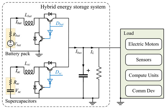
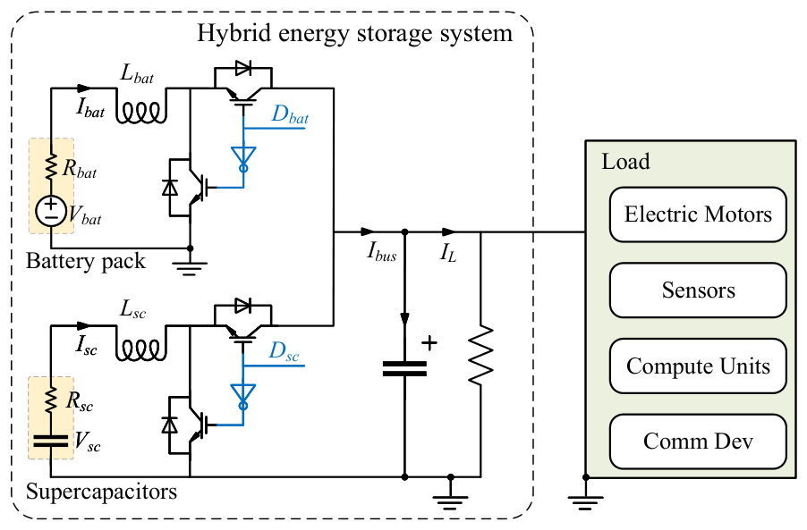
The HESS is the core of the normal operation of the machine system, as illustrated in Figure 1. This paper adopts a fully active topology for its greater controllability, supporting more complex power allocation strategies. The energy storage unit of the HESS is composed of lithium-ion batteries and supercapacitors. The lithium-ion batteries provide stable and persistent energy to the system, while the supercapacitors are primarily used to meet the system’s transient high-power demands. The HESS provides energy for all types of loads required for system operation, such as electric motors, sensors, computing units, and communication devices. The HESS and load interact through the DC bus controlled by the power allocation to ensure energy balance.
Figure 1.
Schematic diagram of the HESS.
2.2. Battery Model
The battery pack in the HESS consists of lithium-ion battery cells, which are represented by the commonly used equivalent internal resistance model, as shown in Figure 1. In this model, denotes the terminal voltage of the battery pack, represents the current of the battery pack, and indicates the internal resistance of the battery pack.
The SoC of the battery pack needs to be obtained through indirect calculation. In this paper, the coulomb counting method is used to estimate the SoC of the battery pack in real-time. The calculation formula is as follows:
where is the SoC of the battery pack at time t, is the initial time, and is the battery capacity, representing the total charge the battery pack can store.
2.3. Battery Aging Model
This paper adopts a semi-empirical lithium-ion battery degradation model, in which cycling-induced capacity loss is related to ampere-hour throughput, current rate, and temperature [28,29]. Based on the parameter tuning method in [28], the aging model can be expressed as follows:
where is the battery capacity loss, is the empirical coefficient , R denotes the gas constant , T is the absolute battery temperature, is the ampere-hour throughput, and is the current rate, defined as . The parameter z is the exponential factor , and represents the battery activation energy, defined as .
According to (2), the discrete lithium-ion battery degradation formula can be obtained as follows:
where is the sampling time interval, and denotes the incremental battery capacity loss during one sampling interval.
2.4. Supercapacitor Model
In this paper, a first-order RC equivalent circuit model is used to characterize the electrical properties of the supercapacitors, as shown in Figure 1. In this model, represents supercapacitors current, denotes output voltage, and represents internal resistance of the supercapacitors.
The amount of energy stored in the supercapacitors is directly related to the terminal voltage of the supercapacitors. Therefore, the SoC value of the supercapacitors can be estimated by using the following formula.
where denotes the state of charge of the supercapacitor pack, and represents the maximum or nominal voltage of the supercapacitor pack.
When the initial value of the supercapacitors voltage is known, the voltage of the supercapacitors at the next moment can also be determined by the output energy. The discretized formula is as follows:
where represents the output power of the supercapacitor pack at sampling instant k, is the sampling time interval, and is the equivalent capacitance of the supercapacitor pack.
2.5. Model Applicability and Validation Basis
This paper aims to compare different energy management strategies for battery-supercapacitor HESS, rather than to develop new electrochemical models. Therefore, control-oriented equivalent models are adopted for efficient comparative power allocation analysis. Similar battery-supercapacitor HESS configurations have been experimentally evaluated on electric-vehicle prototype platforms with real-time EMS implementation [30].
For battery degradation analysis, a semi-empirical cycle aging model based on ampere-hour throughput, C-rate, and temperature is adopted. Cycle-life models for graphite- cells have been established using extensive tests under different temperature, depth-of-discharge, and C-rate conditions [29]. Thus, the adopted models are suitable for comparing relative degradation and power allocation performance under the same simulation framework.
The degradation model mainly captures cycle aging and does not explicitly model dynamic thermal behavior or calendar aging. However, since all strategies are compared under identical environmental and load conditions, it can still reflect relative battery stress differences caused by different control methods. Similar simplified aging models have also been used in comparative EMS studies [28,29]. More comprehensive multi-factor degradation modeling will be considered in future work, but it is not expected to change the comparative conclusions of this study.
3. Frequency-Aware Optimal Power Allocation for HESS
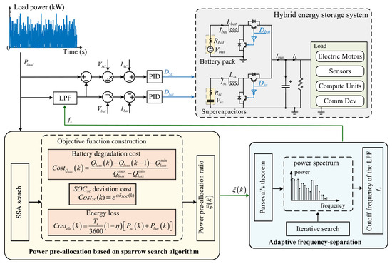
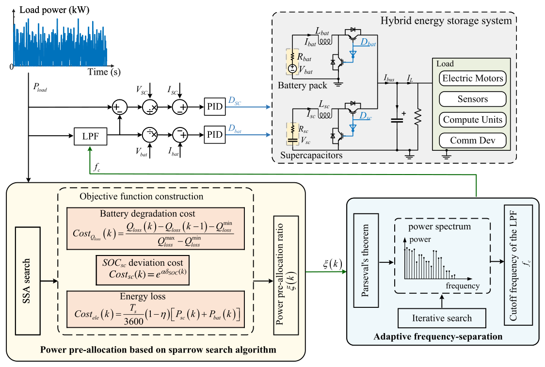
The adaptive frequency-aware power allocation strategy for the HESS proposed in this paper can be divided into two parts: power pre-allocation based on the SSA, and adaptive frequency-splitting of the power signal in the HESS. The structure of the proposed method is shown in Figure 2.
Figure 2.
Schematic of the proposed adaptive frequency-aware power allocation strategy for the HESS in this paper.
3.1. Objective Function Construction for Power Pre-Allocation
First, construct the objective function for the power pre-allocation optimization problem and establish the electrical constraints of the HESS. Then, use the sparrow-inspired algorithm to iteratively search for the optimal power pre-allocation ratio. The key to designing the power pre-allocation optimization objective function is to balance system supply and demand while maintaining system service quality and longevity, slowing battery aging, and keeping supercapacitor SoC within a healthy range. Therefore, the optimization objective function for power pre-allocation comprises three parts: the degradation cost of lithium-ion batteries, the cost of maintaining a healthy SoC for supercapacitors, and the cost of energy loss. Its mathematical form can be represented as follows:
where represents the objective function value at time k. , , and denote the battery degradation cost, the supercapacitor SoC deviation cost, and the energy loss cost, respectively. The coefficients , , and are weighting factors used to adjust the relative importance of battery degradation mitigation, supercapacitor SoC regulation, and energy loss reduction.
The three weighting factors are introduced because these objectives have different physical meanings and may lead to different allocation tendencies. A larger gives higher priority to reducing battery degradation and battery current stress. A larger emphasizes maintaining the supercapacitor SoC near its desired operating range. A larger gives more importance to reducing power conversion losses and internal resistance losses.
In practical operation, these objectives need to be balanced rather than optimized independently. For example, reducing battery degradation may require the supercapacitor to absorb more transient power, which can increase its SoC variation. Strengthening SoC regulation may increase the battery power contribution, while emphasizing energy loss reduction may improve efficiency but weaken the current smoothing effect. Therefore, the weighting design aims to achieve a compromise among battery aging mitigation, supercapacitor SoC regulation, and system energy efficiency.
To balance the capacity loss proportion in the objective function, the minute capacity loss value from a single sampling time step must be linearly normalized to the range [0, 1]. The normalization process is as follows:
where and represent the maximum and minimum capacity loss of the lithium-ion batteries in one time step, respectively.
Without considering the calendar aging of lithium-ion batteries, when the load power is entirely borne by the supercapacitors, the capacity of the lithium-ion batteries is not lost, i.e., Ah. At rated output power, Ah.
To ensure that remains at a moderate level to extend system runtime, this paper considers the cost of deviating from the healthy SoC range. The upper and lower bounds of the healthy SoC range are defined as and , respectively. The deviation of the supercapacitor SoC from the healthy range is defined as:
Then, the supercapacitor SoC deviation cost is calculated as follows:
where denotes the minimum distance between the current supercapacitor SoC and the healthy SoC range, x is an arbitrary SoC value within the healthy range, and is a positive coefficient used to adjust the penalty intensity of the supercapacitor SoC deviation.
The cost of energy loss is calculated as follows:
where represents the conversion efficiency of the bidirectional DC/DC converter, and and denote the actual output powers of the battery pack and supercapacitor pack at sampling instant k, respectively.
The actual output power of the lithium-ion batteries includes both the load power and the power used to charge the supercapacitors. Considering the loss power due to internal resistance heating in both components, their actual output power can be expressed as follows:
where is the load power demand at sampling instant k, represents the ratio of load power supported by the battery pack, and denotes the current associated with power transfer between the battery pack and the supercapacitor pack.
Constraining is crucial for solving optimization problems, ensuring that the solutions adhere to physical characteristics and limiting the solution space. To prevent overcharging and overdischarging of the lithium-ion batteries and supercapacitor, and to ensure that their optimal output power remains within feasible ranges, the constraints are expressed as follows:
where and are the maximum and cutoff voltages of the battery pack, and are the maximum and minimum voltages of the supercapacitor pack, is the pre-allocated power of the supercapacitor pack, is the pre-allocated power of the battery pack, is the rated power of the supercapacitor pack, and is the rated power of the battery pack. The state variables in the optimization problem include , and the control variables include .
3.2. Power Pre-Allocation Based on Sparrow Search Algorithm
The sparrow heuristic search algorithm enhances the ability to find the global optimum by simulating the foraging behavior of sparrows, addressing optimization problems under multiple constraints. In the SSA, each sparrow’s position represents a set of variables to be optimized. In the constructed power pre-allocation optimization problem, the control variable set is . The positions of the sparrow population can be represented in matrix form as follows:
where denotes the sparrow population position matrix, with n sparrows and three columns corresponding to , , and , respectively.
In the SSA, the position of each sparrow is used to calculate the corresponding fitness function. By comparing the fitness before and after position updates, it is determined whether the new position should be retained. In this paper, the fitness function of the SSA is the objective function constructed in the previous section. Therefore, the calculation formula for the objective function of the sparrow population can be expressed as follows:
where denotes the fitness-value vector of the sparrow population, and each element represents the objective function value corresponding to one sparrow position.
The SSA begins by initializing the positions of the population and assigning roles based on the fitness function values of each sparrow’s position. The population comprises two roles: explorers and followers, maintaining a fixed ratio. Both roles have three state changes: becoming an explorer, becoming a follower, or entering the alert state.
In each iteration, the sparrows with the lowest fitness values become explorers. The main behaviors of explorers are providing foraging directions to followers (searching for optimal solutions) and guiding followers to safe zones (global search capability). These behaviors can be mathematically described as follows:
where denotes the position of the i-th sparrow at iteration t, is the iteration number, and are the alert value and threshold, respectively, is a random number, follows a normal distribution, and Z is a all-one matrix. If , discoverers escape the area; otherwise, they search for better positions.
Sparrows in the population that cannot become discoverers will become followers. The main roles of followers include flying away from the group to find new feeding spots (exploring possible global optima) and following the discoverer with the highest fitness value (searching for local optima). These behaviors for updating the position of followers can be mathematically described as follows:
where represents the worst position during the iteration, , and represents the best position of the current discoverer. Followers in poor positions will abandon the discoverer and search for new feeding spots, exploring better areas. Other followers will move closer to the discoverer.
Followers and discoverers in the sparrow population can enter the alert state. In each iteration, the sparrows that transition to the alert state are random, but their number remains constant. The position update formula for sparrows in the alert state is as follows:
where and denote the best and worst positions during the iteration, respectively. is a normally distributed random number, and is a small positive constant used to avoid division by zero. If , the alert sparrow moves from the edge toward the center; if , the central alert sparrow approaches others.
Based on the objective function derived from the optimization problem, the SSA is used to solve the power pre-allocation ratio while satisfying the electrical performance constraints of the HESS. The detailed solution process is shown in Algorithm 1.
| Algorithm 1 Power Pre-allocation Based on the Sparrow Search Algorithm | |
| Require: Maximum number of iterations , | |
| Ensure: | |
| 1: | Initialize position of sparrow population using (13), set iteration count |
| 2: | Initialize and |
| 3: | Calculate using (14) and sort them in ascending order |
| 4: | while do |
| 5: | Divide the sparrow population into discoverers and followers in a 1:4 ratio |
| 6: | Randomly generate |
| 7: | repeat |
| 8: | Update discoverer positions using (15) |
| 9: | Update follower positions using (16) |
| 10: | Randomly select 10% of the sparrows to become alert state and update their positions using (17) |
| 11: | until satisfy the constraints of (12) |
| 12: | Calculate using (14) and sort them in ascending order |
| 13: | if then |
| 14: | |
| 15: | Update |
| 16: | end if |
| 17: | |
| 18: | end while |
| 19: | End of algorithm |
3.3. Frequency-Domain Power Transformation and Quantitative Allocation
The proposed optimal frequency-aware power allocation strategy is an online, real-time method. For discrete computation of the power allocation strategy, the discrete equivalent form of Parseval’s theorem is necessary. Thus, Parseval’s theorem is discretely represented using the discrete Fourier transform (DFT), as follows:
where , , and N denote the n-th time-domain sample, the k-th DFT frequency component, and the number of samples in the time-domain window, respectively.
Truncating and sampling the load power signal can cause spectral leakage in the Fourier transform (FT), leading to energy loss in the frequency domain. To mitigate spectral leakage caused by truncating and sampling, a Hanning window is applied, as follows:
where is the Hanning window vector, is its value at the n-th time-domain sample, and N is the window length. A larger N improves frequency resolution but increases computational load. In this paper, and are used.
After discretizing the load power signal, the vector form of the signal is obtained. The windowing process can be expressed as vector multiplication:
where denotes the windowed discrete load-power signal and is the window correction factor. The FFT gives the frequency-domain signal :
where denotes the frequency-domain signal obtained from the windowed load power signal.
The power spectrum of the load power signal can characterize the power distribution of various frequency components and can be calculated as follows:
where represents the two-sided power spectrum of the load power signal, ∘ denotes element-wise multiplication, and denotes the complex conjugate operator. The two-sided power spectrum contains both positive and negative frequencies, which are symmetrical about the center. The energy in the positive and negative frequency ranges is identical. To reduce computational complexity, the two-sided power spectrum can be converted to a single-sided power spectrum as follows:
where is the length of the frequency domain signal. The signal length N in the time domain is different from the length in the frequency domain. To ensure that the load power signal lengths in the time and frequency domains are equal, the length of the single-sided power spectrum in the frequency domain must be adjusted. The energy conservation formula for the load power signal in the time and frequency domains can be obtained as follows:
where is the length correction term between the time domain and frequency domain load power signals.
According to Parseval’s theorem, the total energy of the load power signal is preserved between the time and frequency domains. Therefore, the power pre-allocation ratio obtained by SSA in the time domain can be equivalently interpreted as an energy allocation ratio in the frequency domain. If the battery is assigned a proportion of the total load power, it should ideally absorb frequency components whose cumulative spectral energy equals , where denotes the total energy of the single-sided power spectrum. Since low-frequency components correspond to slowly varying power demand, while high-frequency components mainly represent transient fluctuations, allocating cumulative low-frequency energy to the battery ensures consistency between time-domain power allocation and frequency-domain energy distribution. Consequently, the cutoff frequency is determined as the frequency at which the cumulative spectral energy first reaches .
Based on the single-sided power spectrum of the load power signal and the pre-allocation ratio obtained in the previous section, the frequency point for splitting high- and low-frequency components can be adaptively calculated. First, the total energy of the single-sided power spectrum needs to be calculated as follows:
The adaptive frequency separation searches for the smallest frequency boundary such that the cumulative low-frequency spectral energy matches the battery energy allocation determined by SSA. This ensures that the low-pass filter cutoff frequency is physically consistent with the optimal power pre-allocation ratio.
Then, starting from the lowest frequency, the energy of each frequency component is iteratively accumulated until it exceeds the pre-allocated energy for the lithium-ion battery. The frequency at this point is output as the cutoff frequency , which is used as the cutoff frequency of the LPF, completing the adaptive frequency splitting of the power signal. The entire adaptive frequency splitting calculation process is shown in Algorithm 2.
| Algorithm 2 Load Power Signal Adaptive Frequency Splitting Calculation | |
| Require: , | |
| Ensure: Frequency-splitting point | |
| 1: | Initialize parameter , |
| 2: | Set the sampling frequency and the Hanning window size |
| 3: | Calculate the Hanning window |
| 4: | Sample the load power signal |
| 5: | Apply the Hanning window to the sampled load power signal |
| 6: | Apply FFT to the windowed signal |
| 7: | Calculate the one-sided power spectrum |
| 8: | Calculate the total energy of the power spectrum |
| 9: | while do |
| 10: | |
| 11: | |
| 12: | end while |
| 13: | Calculate the frequency signal point |
| 14: | End of algorithm |
In addition to positive load demand, the proposed energy management strategy can also be extended to bidirectional power flow conditions involving negative power requests, such as regenerative braking or energy recovery. In such cases, negative load power represents reverse energy flow from the load side to the hybrid energy storage system.
Since the proposed SSA–FFT framework operates on the signed load power signal, the frequency-domain decomposition remains valid under both positive and negative power conditions. The adaptive frequency separation mechanism can therefore allocate low-frequency recovered energy to the battery and high-frequency transient recovery energy to the supercapacitor using the same quantitative allocation principle.
This enables the proposed method to maintain consistent energy-sharing behavior under both discharge and charging scenarios.
4. Simulation Results and Discussion
4.1. Simulation Scenario and Parameter Settings
Load-power fluctuations may result from machine operating mode, travel speed, task execution, route conditions, road gradients, turning maneuvers, and obstacle avoidance. Therefore, representative task-based operating conditions are used to evaluate the adaptability of the proposed method under different load fluctuation characteristics.
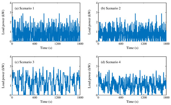
To ensure reproducibility, the load generation procedure and key parameters are specified. Four profiles, denoted as Scenarios 1–4, are generated as datasets 001–004 using a two-stage random task synthesis procedure. First, a background aperiodic load is generated by randomly superimposing multiple overlapping tasks to represent baseline machine power demand. Second, scheduled task loads are added according to predefined strategies, including FP, EDF, and the proposed NEW strategy. Thus, the profiles retain both random fluctuations and task-scheduling constraints, and emulate typical load variations in HESS-equipped mobile or industrial machines rather than arbitrary random signals. The generated load profiles are shown in Figure 3.
Figure 3.
Load power profiles under four representative operating scenarios. (a) Scenario 1, (b) Scenario 2, (c) Scenario 3, (d) Scenario 4.
Specifically, Figure 3a shows Scenario 1, which represents a continuous operating condition with sustained average power demand and noticeable random fluctuations. It should not be regarded as a strictly steady-state load, but as a continuous operation scenario with task-induced power variations, such as a mobile robot or industrial electric platform performing continuous movement with varying onboard tasks. Figure 3b shows Scenario 2, which represents periodic acceleration/deceleration or periodic task execution. This profile emulates operating conditions where load demand varies periodically due to repeated motion commands, speed changes, or cyclic task scheduling. Figure 3c shows Scenario 3, which represents an intermittent operating condition with short-duration tasks and brief low-load intervals. Such a profile can occur when a machine alternates between active task execution and temporary standby or low-power operation. Figure 3d shows Scenario 4, which represents a lightweight repeated-task condition. Compared with the other scenarios, this profile has lower load demand but more frequent power variations, making it suitable for evaluating whether the proposed method can maintain stable battery current and supercapacitor SoC under repeated low-to-medium power changes.
Overall, the four scenarios cover different practical load characteristics, including continuous operation with random fluctuations, periodic load variation, intermittent task execution, and lightweight repeated operation. The main parameter settings used to generate these representative load profiles are summarized in Table 1. These profiles enable the proposed energy management strategy to be evaluated under diverse operating conditions rather than a single fixed or idealized load profile.
Table 1.
Main parameter settings for random load generation.
The lithium-ion battery cell used in this paper is a lithium iron phosphate battery 18500-3.2V, with an internal resistance of 1.5 mΩ and a rated cycle life of 3500 cycles. The battery pack adopts an 18-series 9-parallel configuration. The supercapacitor cell is the Maxwell-2.7V, with a capacitance of 100 F, and the supercapacitor module adopts a 20-series 2-parallel configuration.
The initial voltage of the supercapacitor was 30 V, corresponding to an initial SoC of 55%. The initial voltage of the lithium-ion battery was 62 V, corresponding to an initial SoC of 80%, and the simulation duration was 1800 s. The main parameters of the battery pack and supercapacitor pack are summarized in Table 2.
Table 2.
Parameters of the battery pack and supercapacitor pack in HESS.
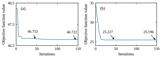
Figure 4 shows the single optimization convergence process of SSA under given system state variables. To balance computational efficiency and performance, the sparrow population size was set to 25, with 100 iterations. This configuration ensures adequate solution space exploration within acceptable computation time, effectively balancing load power between the supercapacitor and lithium-ion battery. Performance tests with 150 iterations showed that the algorithm converges within 100 iterations. The objective function value decreases rapidly in the first 20 iterations, indicating efficient exploration of the solution space. From the 50th to the 150th iteration, the value continues to decrease gradually, reflecting steady convergence and the refined search capability of SSA in later stages, which helps prevent premature convergence to local optima.
Figure 4.
The single optimization convergence process of SSA with given system state variables, , , , and . (a) , (b) .
In addition to the convergence analysis, the computational complexity, decision time, and real-time feasibility of the proposed SSA-based optimization are further evaluated in the following subsection.
4.2. Performance Analysis of the Results
For the computational complexity expressions, , , and d denote the number of SSA iterations, the sparrow population size, and the dimension of the optimization variables, respectively. , , and denote the number of stages, states, and control candidates in the DP benchmark, respectively.
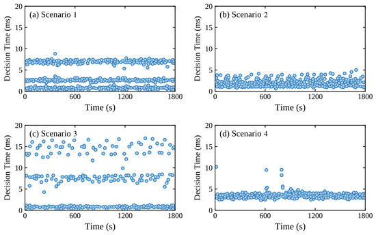
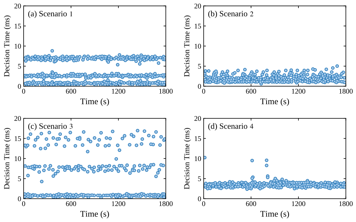
To evaluate the engineering applicability of the proposed method, the computational complexity, execution time, and real-time performance of different power allocation strategies are analyzed. The proposed strategy mainly includes SSA-based power pre-allocation and FFT-based frequency-domain allocation. The runtime comparison and computational complexity are summarized in Table 3, and the SSA decision-time distribution under the four main scenarios is shown in Figure 5.
Table 3.
Runtime comparison and computational complexity of different methods.
Figure 5.
Decision time distribution of the SSA algorithm under Scenarios 1–4.
As shown in Table 3, the proposed SSA-based method requires more computation than SOP and LPF because it iteratively optimizes the power pre-allocation ratio. This additional cost enables quantitative power pre-allocation and frequency-aware power separation. DP serves as an offline benchmark, but its state-control grid search causes a much higher computational burden and limits direct online implementation. In the pure MATLAB R2025b interpreted environment, the SSA module has an average runtime of 15.19–54.08 ms and a maximum runtime of 169.44 ms under the most complex condition.
Figure 5 further shows the SSA decision-time distribution over the 1800 s simulation horizon for Scenarios 1–4. Most samples remain within the low-millisecond range, indicating stable computational behavior under different random load profiles. These runtime results were obtained without compilation optimization. In practical HESS deployment, common real-time control periods are typically 10 ms or 100 ms, and MATLAB-based optimization algorithms can be further accelerated by conversion into C/C++ code using MATLAB Coder.
From the perspective of algorithmic complexity, the computational complexity of the main components and the overall proposed method can be summarized as:
where , , , and denote the complexity of SSA-based optimization, FFT operation, cumulative spectral-energy search, and the overall method, respectively. , , and d represent the maximum iterations, sparrow population size, and optimization-variable dimension, respectively. N denotes the sampling window length.
Because the simulation control step is small ( s), an offline pre-allocation and heuristic mapping function, denoted as Ksc Fun, was adopted in Simulink to avoid repeated SSA iterations at every step. This strategy preserves the SSA-based allocation mechanism while satisfying the time-step requirement. Overall, although the proposed method introduces additional computation compared with simple filtering methods, this cost is associated with its optimization capability. With proper implementation optimization or pre-allocation mapping, the proposed strategy can potentially meet real-time HESS energy management requirements.
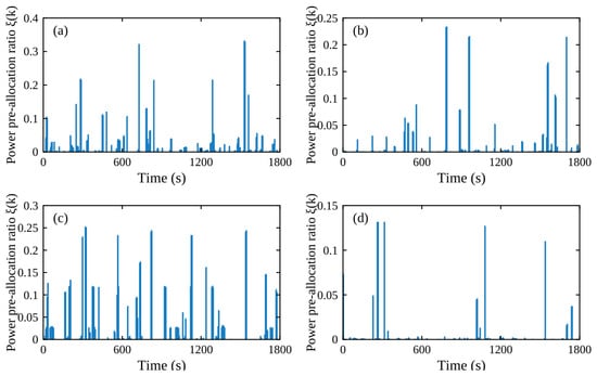
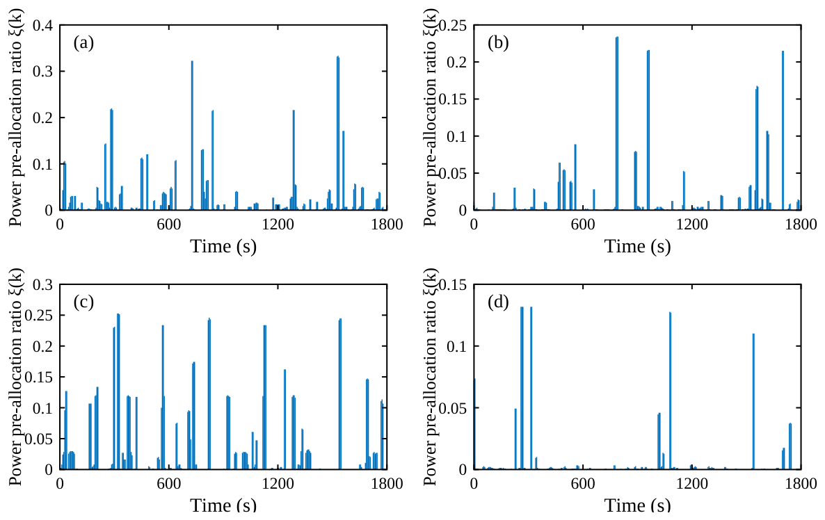
Figure 6 shows the power pre-allocation ratio determined by SSA under four simulation scenarios. The maximum ratios for power pre-allocation to the battery pack were 0.3852, 0.2205, 0.295, and 0.1238, respectively. These low ratios indicate the low load power assignment to the battery pack. At certain times, the pre-allocation ratio was 0, meaning the supercapacitor pack can alone handle the relatively low load power.
Figure 6.
SSA power pre-allocation ratios under four random simulation scenarios: (a) Scenario 1; (b) Scenario 2; (c) Scenario 3; (d) Scenario 4.
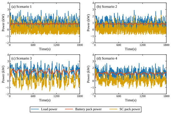
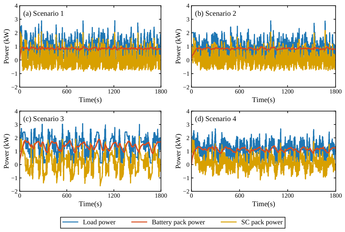
The power allocation results are obtained through the proposed adaptive frequency-separation method according to the SSA-derived pre-allocation ratios. Across all simulation scenarios, the proposed method effectively reduces power fluctuations in the battery pack. In contrast, the supercapacitors exhibit more significant power fluctuations, indicating that they are effectively utilized to balance load demand. By absorbing high-frequency components, the supercapacitors help reduce the aging rate of the battery pack, as shown in Figure 7.
Figure 7.
The load power allocation results of the proposed method are obtained under the four random simulation scenarios.
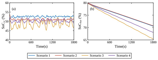
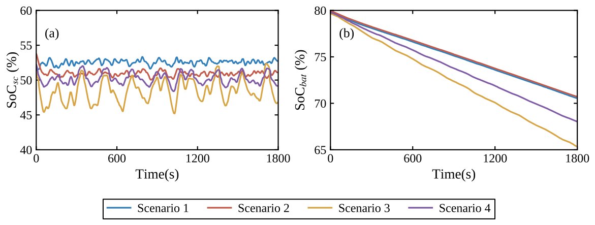
Figure 8a illustrates the SoC variation of the supercapacitors during the simulation. In all four scenarios, the supercapacitor SoC remains between 45% and 55%, demonstrating that the proposed method effectively maintains the SoC within a healthy range, better balancing the energy distribution in the HESS and ensuring efficient system operation. Figure 8b presents the SoC curve of the battery pack in the HESS, showing that the proposed method mainly uses the lithium-ion battery pack for power supply while the supercapacitors serve as an auxiliary component.
Figure 8.
SoC curves under four simulation scenarios: (a) SoC of the supercapacitor pack; (b) SoC of the battery pack.
A weight sensitivity analysis was conducted to examine the influence of the three objective-function weights on the optimized power pre-allocation ratio. Four relative weight settings were tested under a representative load condition. The baseline setting gives equal priority to battery degradation mitigation, supercapacitor SoC regulation, and energy loss reduction, while the other settings increase one weight at a time.
Table 4 summarizes the results. Compared with the baseline, increasing the battery degradation weight to reduces the optimal ratio from 0.3317 to 0.3000, indicating a lower battery power contribution for aging mitigation. Increasing the supercapacitor SoC regulation weight to slightly raises the ratio to 0.3351, helping the supercapacitor recover toward the desired SoC range. Increasing the energy loss weight to changes the ratio to 0.3250, reflecting an efficiency-oriented compromise. Therefore, the baseline setting provides a balanced trade-off among battery degradation mitigation, supercapacitor SoC regulation, and system energy efficiency.
Table 4.
Weight sensitivity analysis of the objective function.
4.3. Adaptive Frequency Separation Visualization
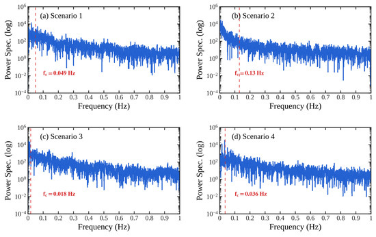
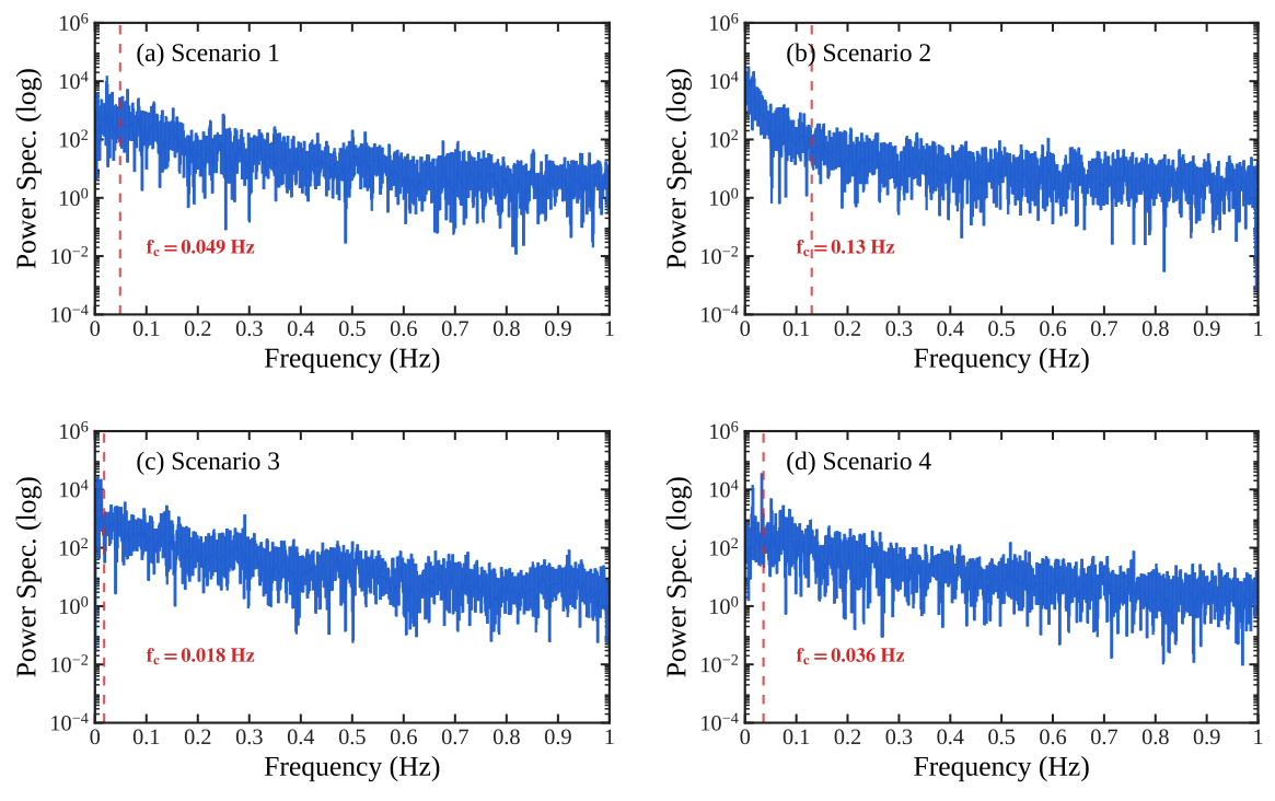
To further illustrate the adaptive behavior of the proposed frequency separation method, Figure 9 presents the power spectral densities of the four load scenarios, with the adaptive cutoff frequencies identified by the proposed method marked by red dashed lines. It can be observed that different load profiles exhibit distinct spectral energy distributions. The proposed method dynamically determines the cutoff frequency based on the cumulative spectral energy corresponding to the SSA-derived pre-allocation ratio. These results demonstrate that the frequency splitting point adapts to the frequency characteristics of the load, enabling consistent allocation of low-frequency components to the battery and high-frequency components to the supercapacitor across different operating conditions.
Figure 9.
Power spectra of the four load scenarios and the adaptive cutoff frequencies identified by the proposed method. The red dashed lines indicate the cutoff frequency determined for each scenario.
4.4. Comparison with Existing Methods
In order to validate the effectiveness of the proposed method, a comparison was conducted with three existing methods. Dynamic Programming (DP) is used as a classical offline optimization benchmark. In DP, the battery voltage and bus voltage are assumed to be constant at 57.6 V and 72 V, respectively, and the converter is considered ideal. Method 1 proposes power pre-allocation rules in eight different regions based on the SoC of the battery pack and supercapacitors, followed by a low-pass filter for frequency separation and energy management [26]. Method 2 converts the load power from the time domain to the frequency domain and selects the frequency component with the largest spectral proportion as the adaptive frequency separation point. Fixed upper and lower cutoff frequency limits are also imposed to constrain the adaptive frequency point [24].
To evaluate the effectiveness of the proposed power allocation strategy, the following three performance metrics are selected:
- (1)
- : calculated using Equation (3), it is used to evaluate the lifespan degradation of the lithium-ion battery. A lower value indicates better performance in reducing battery degradation.
- (2)
- Battery discharge current RMS (): RMS is used to measure the fluctuation amplitude of a set of data. In this paper, the battery current RMS is used to evaluate the fluctuation of the battery discharge current during system operation. The battery current RMS can be expressed as follows:where denotes the total number of current samples used for RMS calculation.
- (3)
- End-of-simulation supercapacitor SoC: during system operation, the supercapacitor SoC should be maintained around 50%. Therefore, the final supercapacitor SoC is used to evaluate the SoC regulation performance.
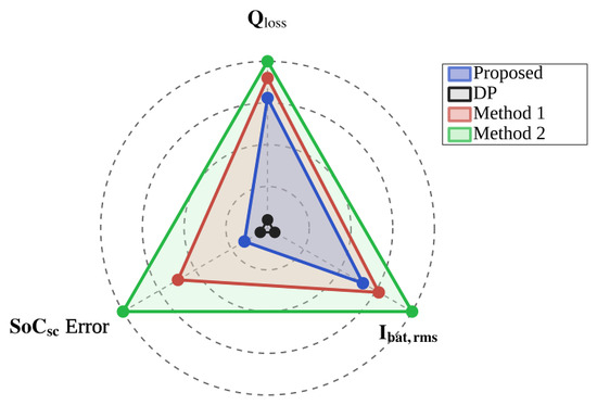
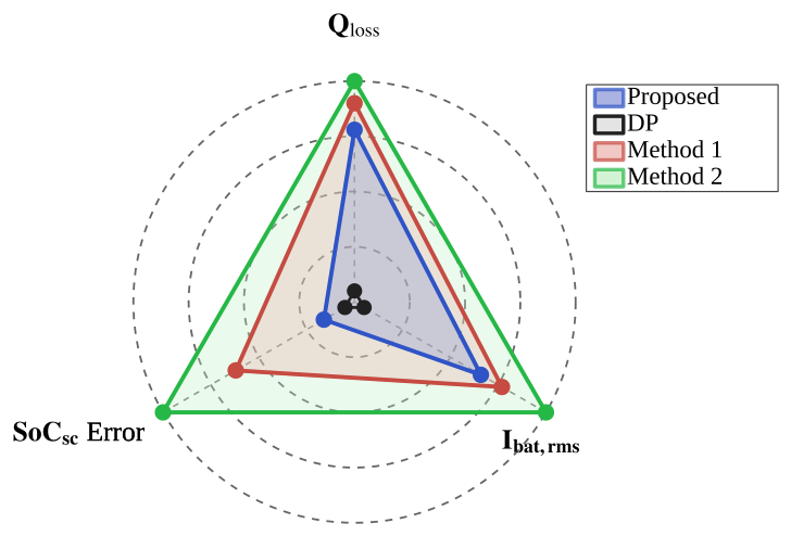
Figure 10 provides a visual comparison of the overall performance of different methods in Scenario 1. Among these methods, DP consistently achieves the best benchmark performance because it is an offline global optimization method. However, the proposed method provides a favorable balance among battery degradation reduction, current smoothing, supercapacitor SoC regulation, and online implementability. Compared with Method 1, the proposed method reduces by 1.23% to 6.32% and by 0.98% to 6.04%. Compared with Method 2, the proposed method reduces by 6.12% to 11.41% except in Scenario 2, and reduces by 6.12% to 12.56% except in Scenario 2. Although Method 2 achieves lower and than the proposed method in Scenario 2, it fails to maintain the terminal around 50%, indicating poorer supercapacitor SoC regulation. The detailed values of the three evaluation metrics for all methods under different scenarios are summarized in Table 5.
Figure 10.
Performance radar chart comparing the proposed method with DP, Method 1, and Method 2 for Scenario 1. A smaller enclosed area indicates better overall performance.
Table 5.
Comparative analysis of the proposed method alongside DP, Method 1, and Method 2 across three evaluation metrics.
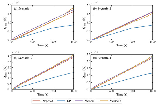
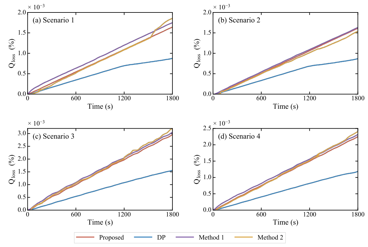
Figure 11 compares the battery degradation performance of different methods under the four simulation scenarios. The proposed method generally achieves lower than Method 1 and Method 2, while DP obtains the lowest because of its offline global optimization nature. In Scenario 1, Method 2 performs well during the initial stage, but its increases rapidly after approximately 1400 s. In Scenario 2, Method 2 outperforms the proposed method in terms of , indicating that its degradation-reduction performance is sensitive to operating conditions. In contrast, the proposed method maintains more stable degradation performance across different scenarios.
Figure 11.
The curves for different methods under the simulation scenarios.
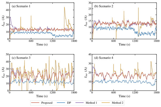
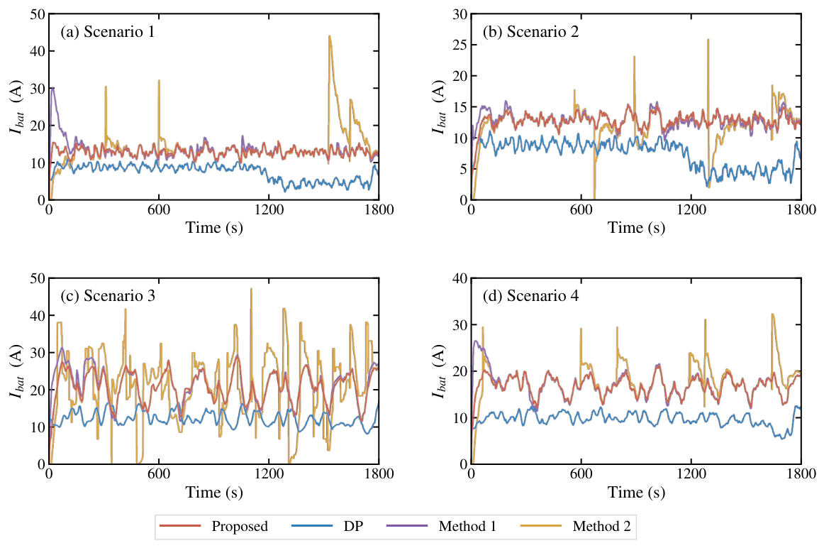
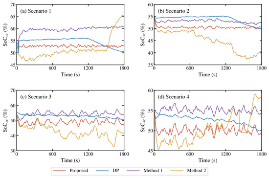
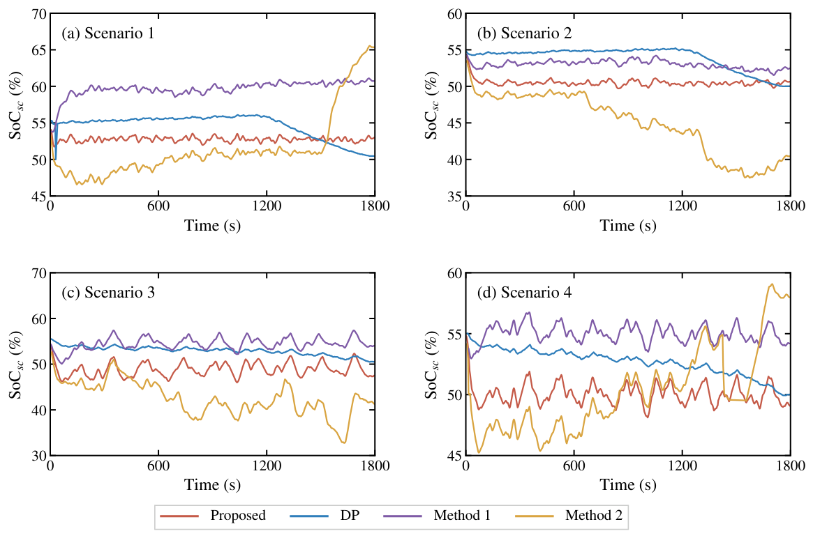
Figure 12 and Figure 13 compare the battery current profiles and supercapacitor SoC trajectories obtained by different methods, respectively. As the offline benchmark, DP exhibits the best current smoothing performance. Method 2 shows noticeable transient fluctuations in , resulting in poorer current-output stability. The proposed method provides smoother battery current than Method 1 in the initial stage and achieves better overall current stability across the four scenarios. Although the value of Method 2 in Table 5 is not significantly higher than that of the proposed method, and is even lower in Scenario 2, its transient fluctuations remain more severe, indicating that the proposed method provides more stable battery current regulation.
Figure 12.
The curves for different methods under the simulation scenarios.
Figure 13.
The performance under different simulation scenarios.
For the supercapacitor SoC, Method 2 exhibits the largest fluctuations across different scenarios because it does not sufficiently consider supercapacitor SoC regulation. This makes it difficult to maintain around the desired 50% level. The proposed method maintains around 50% while effectively utilizing the supercapacitors to assist the HESS power supply. Method 1 achieves a similar SoC regulation effect, but its remains consistently higher than that of the proposed method, indicating a more conservative supercapacitor utilization strategy. Therefore, the proposed method is more effective in leveraging the role of the supercapacitors within the HESS system.
The effectiveness of the proposed frequency-aware allocation further validates the theoretical assumption that cumulative low-frequency spectral energy can represent the battery’s optimal power share. By adaptively matching spectral energy with the SSA-derived allocation ratio, the method reduces battery current fluctuations while maintaining stable supercapacitor SoC. Although the proposed framework is theoretically applicable to bidirectional power flow, explicit validation under regenerative operating conditions has not been conducted in this study. Future work will include simulation and experimental verification under regenerative braking and other energy recovery scenarios.
5. Conclusions
This paper proposes an adaptive frequency-separation power allocation strategy based on SSA for HESS, aimed at dynamically distributing power between the lithium-ion battery pack and the supercapacitors according to the frequency characteristics of the load power, thereby enhancing the efficiency and lifespan of the HESS. The proposed method first utilizes the SSA to explore the solution space of the constructed objective function, obtaining the pre-allocation proportion of load power assigned to the battery pack. Subsequently, the load power is transformed from the time domain to the frequency domain, and the pre-allocation results are adaptively processed to calculate the cutoff frequency of the low-pass filter. Ultimately, this enables the energy management of the HESS, where the battery pack handles the low-frequency component of the load power, and the supercapacitors absorb the high-frequency component. The effectiveness of the proposed method is validated through comprehensive simulations and a comparative analysis with DP and other existing methods. The proposed method reduces , mitigates lithium-ion battery degradation, maintains the supercapacitor’s SoC within a healthy range, and smooths battery current fluctuations, thereby extending the operational life and enhancing the performance of machine system with the HESS. Moreover, compared to the comparison methods, the proposed method demonstrates better adaptability and exhibits stable power allocation strategy performance across different scenarios, which is crucial for the diverse and dynamic environments where such systems operate.
Author Contributions
Conceptualization, L.G., J.L. and W.L.; methodology, J.L. and Z.J.; software, Z.Z.; validation, Z.J. and Z.Z.; formal analysis, L.G. and W.L.; investigation, J.L., Z.J. and Z.Z.; resources, J.L. and W.L.; data curation, Z.Z.; writing—original draft preparation, L.G., J.L. and Z.J.; writing—review and editing, Z.Z. and W.L.; visualization, Z.J.; supervision, L.G. and W.L.; project administration, L.G.; funding acquisition, J.L. All authors have read and agreed to the published version of the manuscript.
Funding
This research received no external funding.
Data Availability Statement
The data and materials used to support the findings of this study are available from the corresponding author upon reasonable request.
Conflicts of Interest
The authors declare no conflicts of interest.
Nomenclature and Abbreviations
Main symbols used in this paper.
| Symbol | Definition |
| k | Discrete sampling instant |
| t | Time |
| Sampling time interval | |
| Load power demand at sampling instant k | |
| Output power of the battery pack at sampling instant k | |
| Output power of the supercapacitor pack at sampling instant k | |
| Pre-allocated power of the battery pack at sampling instant k | |
| Pre-allocated power of the supercapacitor pack at sampling instant k | |
| Battery current at sampling instant k | |
| Supercapacitor current at sampling instant k | |
| Current associated with power transfer between the battery pack and the supercapacitor pack | |
| Terminal voltage of the battery pack at sampling instant k | |
| Terminal voltage of the supercapacitor pack at sampling instant k | |
| Internal resistance of the battery pack | |
| Internal resistance of the supercapacitor pack | |
| Battery capacity | |
| Battery capacity loss | |
| Maximum battery capacity loss in one sampling step | |
| Minimum battery capacity loss in one sampling step | |
| Battery current rate | |
| Ampere-hour throughput | |
| Battery activation energy | |
| R | Gas constant |
| T | Absolute battery temperature |
| z | Exponential factor in the battery degradation model |
| Empirical coefficient in the battery degradation model | |
| State of charge of the battery pack at sampling instant k | |
| State of charge of the supercapacitor pack at sampling instant k | |
| Upper bound of the healthy SoC range | |
| Lower bound of the healthy SoC range | |
| Deviation from the healthy SoC range at sampling instant k | |
| Power pre-allocation ratio of the battery pack at sampling instant k | |
| Objective function value | |
| Battery degradation cost at sampling instant k | |
| Supercapacitor SoC deviation cost at sampling instant k | |
| Energy loss cost at sampling instant k | |
| Weighting factor for battery degradation mitigation | |
| Weighting factor for supercapacitor SoC regulation | |
| Weighting factor for energy loss reduction | |
| Conversion efficiency of the bidirectional DC/DC converter | |
| Position matrix of the sparrow population | |
| n | Number of sparrows in the population |
| Number of SSA iterations | |
| Population size of SSA | |
| d | Dimension of the optimization variables |
| Alert value in SSA | |
| Alert threshold in SSA | |
| Sampling frequency | |
| Cutoff frequency of the low-pass filter | |
| N | Length of the time-domain window |
| Length of the frequency-domain signal | |
| Discrete load power signal in the time domain | |
| Windowed discrete load power signal in the time domain | |
| Frequency-domain signal obtained by FFT | |
| Hanning window vector | |
| Window correction factor | |
| Two-sided power spectrum of the load power signal | |
| Single-sided power spectrum of the load power signal | |
| Total energy of the single-sided power spectrum | |
| Accumulated low-frequency spectral energy | |
| The following abbreviations are used in this manuscript: | |
| HESS | Hybrid energy storage system |
| EMS | Energy management strategy |
| SSA | Sparrow Search Algorithm |
| SoC | State of charge |
| SC | Supercapacitor |
| Li-ion | Lithium-ion |
| LPF | Low-pass filter |
| FFT | Fast Fourier transform |
| DFT | Discrete Fourier transform |
| DP | Dynamic programming |
| MPC | Model predictive control |
| SOP | State-of-power-based method |
References
- Etacheri, V.; Marom, R.; Elazari, R.; Salitra, G.; Aurbach, D. Challenges in the development of advanced Li-ion batteries: A review. Energy Environ. Sci. 2011, 4, 3243–3262. [Google Scholar] [CrossRef] [Scilit]
- Raza, W.; Ali, F.; Raza, N.; Luo, Y.; Kim, K.H.; Yang, J.; Kumar, S.; Mehmood, A.; Kwon, E.E. Recent advancements in supercapacitor technology. Nano Energy 2018, 52, 441–473. [Google Scholar] [CrossRef] [Scilit]
- Sikkabut, S.; Mungporn, P.; Ekkaravarodome, C.; Bizon, N.; Tricoli, P.; Nahid-Mobarakeh, B.; Pierfederici, S.; Davat, B.; Thounthong, P. Control of high-energy high-power densities storage devices by Li-ion battery and supercapacitor for fuel cell/photovoltaic hybrid power plant for autonomous system applications. IEEE Trans. Ind. Appl. 2016, 52, 4395–4407. [Google Scholar] [CrossRef] [Scilit]
- Choi, M.E.; Kim, S.W.; Seo, S.W. Energy management optimization in a battery/supercapacitor hybrid energy storage system. IEEE Trans. Smart Grid 2011, 3, 463–472. [Google Scholar] [CrossRef] [Scilit]
- Yang, Y.; Bremner, S.; Menictas, C.; Kay, M. Modelling and optimal energy management for battery energy storage systems in renewable energy systems: A review. Renew. Sustain. Energy Rev. 2022, 167, 112671. [Google Scholar] [CrossRef] [Scilit]
- Wu, Y.; Huang, Z.; Hofmann, H.; Liu, Y.; Huang, J.; Hu, X.; Peng, J.; Song, Z. Hierarchical predictive control for electric vehicles with hybrid energy storage system under vehicle-following scenarios. Energy 2022, 251, 123774. [Google Scholar] [CrossRef] [Scilit]
- Wu, Y.; Huang, Z.; Zheng, Y.; Liu, Y.; Li, H.; Che, Y.; Peng, J.; Teodorescu, R. Spatial–temporal data-driven full driving cycle prediction for optimal energy management of battery/supercapacitor electric vehicles. Energy Convers. Manag. 2023, 277, 116619. [Google Scholar] [CrossRef] [Scilit]
- Tobajas, J.; Garcia-Torres, F.; Roncero-Sánchez, P.; Vázquez, J.; Bellatreche, L.; Nieto, E. Resilience-oriented schedule of microgrids with hybrid energy storage system using model predictive control. Appl. Energy 2022, 306, 118092. [Google Scholar] [CrossRef] [Scilit]
- Wang, Y.; Wang, L.; Li, M.; Chen, Z. A review of key issues for control and management in battery and ultra-capacitor hybrid energy storage systems. eTransportation 2020, 4, 100064. [Google Scholar] [CrossRef] [Scilit]
- Ma, R.; Song, J.; Zhang, Y.; Zhang, H.; Yuan, M. Lifetime-optimized energy management strategy for fuel cell unmanned aircraft vehicle hybrid power system. IEEE Trans. Ind. Electron. 2022, 70, 9046–9056. [Google Scholar] [CrossRef] [Scilit]
- Yao, Y.; Wang, J.; Zhou, Z.; Li, H.; Liu, H.; Li, T. Grey Markov prediction-based hierarchical model predictive control energy management for fuel cell/battery hybrid unmanned aerial vehicles. Energy 2023, 262, 125405. [Google Scholar] [CrossRef] [Scilit]
- Wu, Y.; Huang, Z.; Li, D.; Li, H.; Peng, J.; Guerrero, J.M.; Song, Z. Integrated battery thermal and energy management for electric vehicles with hybrid energy storage system: A hierarchical approach. Energy Convers. Manag. 2024, 317, 118853. [Google Scholar] [CrossRef] [Scilit]
- Ammari, C.; Belatrache, D.; Touhami, B.; Makhloufi, S. Sizing, optimization, control and energy management of hybrid renewable energy system—A review. Energy Built Environ. 2022, 3, 399–411. [Google Scholar] [CrossRef] [Scilit]
- Zhang, P.; Yan, F.; Du, C. A comprehensive analysis of energy management strategies for hybrid electric vehicles based on bibliometrics. Renew. Sustain. Energy Rev. 2015, 48, 88–104. [Google Scholar] [CrossRef] [Scilit]
- Song, Z.; Hofmann, H.; Li, J.; Han, X.; Ouyang, M. Optimization for a hybrid energy storage system in electric vehicles using dynamic programing approach. Appl. Energy 2015, 139, 151–162. [Google Scholar] [CrossRef] [Scilit]
- Lü, X.; Li, S.; He, X.; Xie, C.; He, S.; Xu, Y.; Fang, J.; Zhang, M.; Yang, X. Hybrid electric vehicles: A review of energy management strategies based on model predictive control. J. Energy Storage 2022, 56, 106112. [Google Scholar] [CrossRef] [Scilit]
- Pisal, P.S.; Vidyarthi, A. An optimal control for power management in super capacitors/battery of electric vehicles using Deep Neural Network. J. Power Sources 2022, 542, 231696. [Google Scholar] [CrossRef] [Scilit]
- Jondhle, H.; Nandgaonkar, A.B.; Nalbalwar, S.; Jondhle, S. An artificial intelligence and improved optimization-based energy management system of battery-fuel cell-ultracapacitor in hybrid electric vehicles. J. Energy Storage 2023, 74, 109079. [Google Scholar] [CrossRef] [Scilit]
- Drungilas, D.; Kurmis, M.; Senulis, A.; Lukosius, Z.; Andziulis, A.; Januteniene, J.; Bogdevicius, M.; Jankunas, V.; Voznak, M. Deep reinforcement learning based optimization of automated guided vehicle time and energy consumption in a container terminal. Alex. Eng. J. 2023, 67, 397–407. [Google Scholar] [CrossRef] [Scilit]
- Li, F.; Li, M.; Wu, Y.; Li, H.; Song, Y.; Huang, Z. Safe reinforcement learning energy management for hybrid electric vehicles: A supervisory action assessment and correction approach. J. Clean. Prod. 2026, 544, 147720. [Google Scholar] [CrossRef] [Scilit]
- Ferahtia, S.; Rezk, H.; Abdelkareem, M.A.; Olabi, A. Optimal techno-economic energy management strategy for building’s microgrids based bald eagle search optimization algorithm. Appl. Energy 2022, 306, 118069. [Google Scholar] [CrossRef] [Scilit]
- Abeywardana, D.B.W.; Hredzak, B.; Agelidis, V.G.; Demetriades, G.D. Supercapacitor sizing method for energy-controlled filter-based hybrid energy storage systems. IEEE Trans. Power Electron. 2016, 32, 1626–1637. [Google Scholar]
- Florescu, A.; Bacha, S.; Munteanu, I.; Bratcu, A.I.; Rumeau, A. Adaptive frequency-separation-based energy management system for electric vehicles. J. Power Sources 2015, 280, 410–421. [Google Scholar] [CrossRef] [Scilit]
- Lee, Y.L.; Lin, C.H.; Chang, C.H.; Liu, H.D.; Chen, C.C. A Novel A Novel Hybrid Energy Storage System with an Adaptive Digital Filter- Based Energy Management Strategy for Electric Vehicles. IEEE Trans. Transp. Electrif. 2023, 10, 5131–5142. [Google Scholar]
- Wu, Y.; Huang, Z.; Liao, H.; Chen, B.; Zhang, X.; Zhou, Y.; Liu, Y.; Li, H.; Peng, J. Adaptive power allocation using artificial potential field with compensator for hybrid energy storage systems in electric vehicles. Appl. Energy 2020, 257, 113983. [Google Scholar] [CrossRef] [Scilit]
- Liao, H.; Peng, J.; Wu, Y.; Li, H.; Zhou, Y.; Zhang, X.; Huang, Z. Adaptive split-frequency quantitative power allocation for hybrid energy storage systems. IEEE Trans. Transp. Electrif. 2021, 7, 2306–2317. [Google Scholar] [CrossRef] [Scilit]
- Boukoberine, M.N.; Zhou, Z.; Benbouzid, M.; Donateo, T. A frequency separation rule-based power management strategy for a hybrid fuel cell-powered drone. In Proceedings of the IECON 2020 The 46th Annual Conference of the IEEE Industrial Electronics Society; IEEE: New York, NY, USA, 2020; pp. 4975–4980. [Google Scholar]
- Song, Z.; Hofmann, H.; Li, J.; Hou, J.; Zhang, X.; Ouyang, M. The optimization of a hybrid energy storage system at subzero temperatures: Energy management strategy design and battery heating requirement analysis. Appl. Energy 2015, 159, 576–588. [Google Scholar] [CrossRef] [Scilit]
- Wang, J.; Liu, P.; Hicks-Garner, J.; Sherman, E.; Soukiazian, S.; Verbrugge, M.; Tataria, H.; Musser, J.; Finamore, P. Cycle-life model for graphite-LiFePO4 cells. J. Power Sources 2011, 196, 3942–3948. [Google Scholar] [CrossRef] [Scilit]
- Zhang, Q.; Li, G. Experimental Study on a Semi-Active Battery-Supercapacitor Hybrid Energy Storage System for Electric Vehicle Application. IEEE Trans. Power Electron. 2020, 35, 1014–1021. [Google Scholar] [CrossRef] [Scilit]

Disclaimer/Publisher’s Note: The statements, opinions and data contained in all publications are solely those of the individual author(s) and contributor(s) and not of MDPI and/or the editor(s). MDPI and/or the editor(s) disclaim responsibility for any injury to people or property resulting from any ideas, methods, instructions or products referred to in the content. |
© 2026 by the authors. Licensee MDPI, Basel, Switzerland. This article is an open access article distributed under the terms and conditions of the Creative Commons Attribution (CC BY) license.