


Abstract
As a high-performance innovative fuel rod design, helical cruciform fuel (HCF) exhibits significant advantages over conventional circular fuel rods, such as a larger heat transfer area per unit volume, enhanced fluid flow and heat transfer characteristics due to its helical geometry, and a periodic self-supporting configuration. These attributes make it a highly promising option for future advanced reactor applications. Using the SST k-ω turbulence model, this study numerically investigates single-phase flow and heat transfer in a triangularly arranged 7-rod compact HCF fuel bundle, focusing on the effects of cross-sectional geometry and helical pitch on its three-dimensional flow and heat transfer behavior. Numerical results indicate that reducing the concave arc radius R increases the heat transfer surface area of the rod bundle, effectively enhancing heat transfer performance and reducing wall temperature; decreasing the helical pitch substantially strengthens fluid mixing. However, when the concave arc radius R becomes excessively small, the cross-flow intensity exhibits a local minimum in the concave region, resulting in a significant degradation of convective heat transfer capability in this area. These findings provide valuable insights for the structural optimization and design selection of HCF.
1. Introduction
The power output of a nuclear reactor is a critical metric of its overall performance, being primarily constrained by the fuel inventory and fuel performance, whereas the design of fuel structural parameters directly defines the performance limits of the reactor. Although conventional cylindrical fuel rods have been widely used, their limitations have become increasingly evident with the development of advanced reactor technologies. The traditional cylindrical fuel rod bundle must rely on spacer grids to maintain the inter-rod spacing and geometric arrangement within the reactor core, and this structural requirement poses a significant engineering constraint in the tight lattice design of advanced compact reactors and small modular reactors (SMRs). Furthermore, the smooth surface of traditional cylindrical fuel renders the fluid in each subchannel relatively independent, with lateral momentum exchange relying solely on turbulent diffusion, resulting in an inherently weak inter-subchannel mixing capability. To overcome th is bottleneck, optimizing the flow and heat transfer characteristics within fuel rod bundle channels to enhance fuel performance has become an important research direction in reactor design. In this context, helical cruciform fuel (HCF) rods have emerged as a novel high-performance fuel element. Their unique helical geometry offers several advantages, including a high surface-area-to-volume ratio, a short heat conduction path, and enhanced fluid mixing, thereby providing a new pathway for improving nuclear reactor performance and demonstrating broad application prospects in the field of advanced reactors. However, despite these recognized advantages, the thermal–hydraulic optimization of HCF geometric parameters remains largely unexplored, particularly for compact reactor configurations where space constraints demand hexagonal fuel arrangements rather than conventional square arrays.
The unique helical structure of HCF rods leads to thermal–hydraulic characteristics that differ significantly from those of conventional round rods, prompting extensive research worldwide. Existing studies can be categorized into three main areas: (1) single-phase mixing and flow characteristics, (2) boiling heat transfer and critical heat flux (CHF) behavior, and (3) experimental validation and pressure drop measurements. In the first category, Xiao et al. [1] established a hybrid model combining fluid sweeping and turbulent mixing for HCF assemblies, concluding that the mixing effect is governed predominantly by forced fluid sweeping. Zhao et al. [2] performed numerical simulations on a 4 × 4 HCF rod bundle, finding that cross-flow mixing is mainly concentrated in valley regions rather than central subchannel areas. Chukhlov et al. [3] conducted numerical simulations on a single petal-shaped fuel rod, finding that fin twisting induces transverse circulation with the transverse velocity component reaching 5% of the axial velocity component. These studies, however, were limited to square arrays with fixed geometric parameters. In the second category, Shirvan et al. [4,5] at MIT employed level-set interface tracking to simulate bubble behavior on HCF surfaces, demonstrating superior departure from nucleate boiling (DNB) performance under low void fraction conditions. Cong et al. [6,7] observed high vapor volume fractions at cruciform fin roots in a 2 × 2 HCF assembly, attributing this to localized high heat flux and delayed void migration under swirling flow. Palumbo [8] performed simulation analyses on U-70at%Zr HCF rods for CANDU reactors, identifying that heat flux concentrates primarily at the root of the cruciform fins, suggesting that DNB-type CHF is more likely to occur at this location. Cai et al. [9] investigated subcooled boiling and CHF in a 3 × 3 HCF bundle under cosine heating conditions, finding significant void fraction differences between peripheral and central subchannels. Du et al. [10] conducted numerical simulations on the onset of nucleate boiling (ONB) in HCF rod bundles, finding that HCF rods exhibit enhanced heat transfer capability and that predictions from existing ONB correlations are generally lower than numerical simulation results. Notably, these boiling studies focused primarily on thermal–hydraulic behavior under fixed geometric configurations, leaving the geometric optimization for enhanced boiling performance largely unaddressed. In the third category, Conboy et al. [11,12,13] conducted thermal–hydraulic experiments using a 4 × 4 square array facility, while Zhang et al. [14] performed pressure drop measurements on a 5 × 5 HCF assembly using particle tracing methods. Based on engineering experimental analysis, Lightbridge Corporation [15] demonstrated that HCF assembly can achieve a power uprate of over 30% for PWRs. These experimental efforts, though valuable, were restricted to specific geometries without systematic parametric variation. Moreover, most geometric designs in these studies were based on minor modifications to the MIT PWR HCF fuel geometric parameters, lacking systematic investigations on geometric parameter variations for triangularly arranged HCF fuel in compact small modular reactors.
Domestic and international scholars have conducted extensive research on HCF, obtaining thermal–hydraulic and pressure drop characteristics of HCF. They also discovered that HCF exhibits circumferentially non-uniform heat flux distribution and periodic variations in flow and temperature fields with helical pitch. However, existing studies on HCF are largely limited to specific geometric cross-section dimensions, with assembly arrangements being mostly in square arrays, offering limited reference value for compact advanced reactors. Based on the practical engineering requirements of compact novel reactors, this paper employs numerical simulation methods to investigate convective heat transfer characteristics of HCF with different structural parameters using a 7-rod hexagonal array assembly. The analysis includes the effects of geometric cross-section dimensions and helical pitch on various parameters, such as pressure drop, flow field, temperature field, and heat flux. Based on numerical simulation results, this paper evaluates the thermal–hydraulic performance of HCF with multiple geometric structural parameters, providing valuable insights for the structural design of HCF in compact advanced reactors.
To address these gaps, this study presents a comprehensive parametric investigation of HCF rods using a 7-rod hexagonal bundle configuration, representing a geometry directly relevant to compact advanced reactors. The specific objectives are: (1) to systematically evaluate the effects of geometric cross-section dimensions (R = 0.07 D–0.28 D) and helical pitch (L = 400–800 mm) on single-phase thermal–hydraulic performance; and (2) to identify optimal geometric parameters that maximize heat transfer enhancement. The baseline design of the geometric cross-section and helical pitch parameters in this study refers to the helical cruciform fuel thermal–hydraulic experiments at MIT and the Russian PIK test reactor. Furthermore, the single-phase baseline established herein provides essential physical insight and validation foundation for subsequent boiling and CHF studies. To the authors’ knowledge, this represents the first systematic optimization of HCF geometric parameters for hexagonal arrangements, offering both immediate design guidance for compact reactors and a fundamental basis for extending to two-phase conditions.
2. Geometry Model of the HCF Assembly and Numerical Considerations
In this study, geometric models of HCF rods with four cross-section dimensions and three helical pitches were established for numerical simulation and analysis. This study evaluated several turbulence models based on HCF pressure drop experiments from MIT. The models included Standard k-ω, Transition SST, SST k-ω, and Realizable k-ε. Based on the validation results, the SST k-ω model was selected for numerical simulations. For mesh generation, mesh independence verification was conducted, and it was determined that the numerical simulation results stabilize when the mesh count reaches 11.16 million. CFD simulations were performed using Fluent 2022 R1.
2.1. Geometric Model
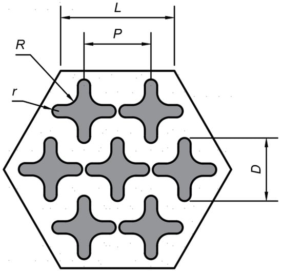
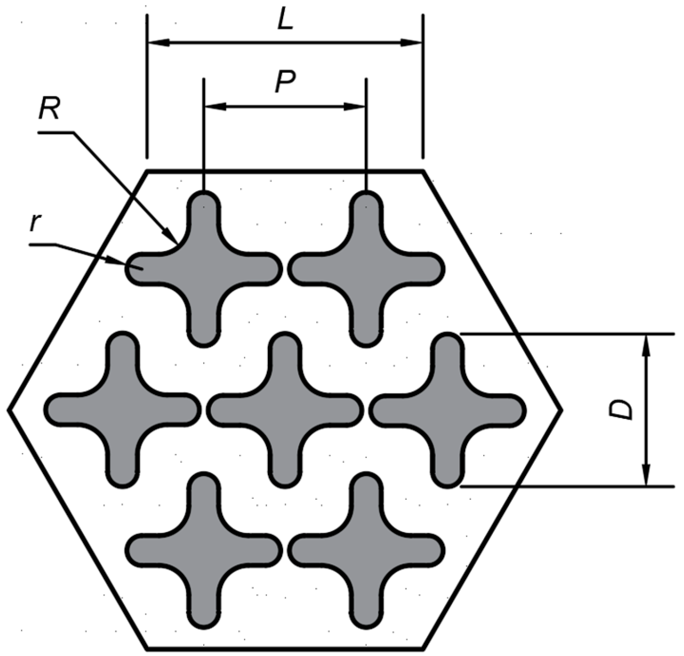
Based on the engineering requirements of compact advanced reactors, this paper conducts numerical simulation analysis on a 7-rod hexagonal array HCF rod bundle, with the cross-section of the fuel assembly shown in Figure 1. The total heated length of the fuel rods is 1.2 m, the rod-to-rod spacing is designed as P, the circumscribed circle diameter of the fuel rod is D, the concave arc dimension of the HCF is R, and the convex arc dimension is r.
Figure 1.
Geometry parameters.
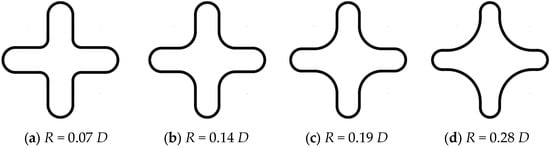
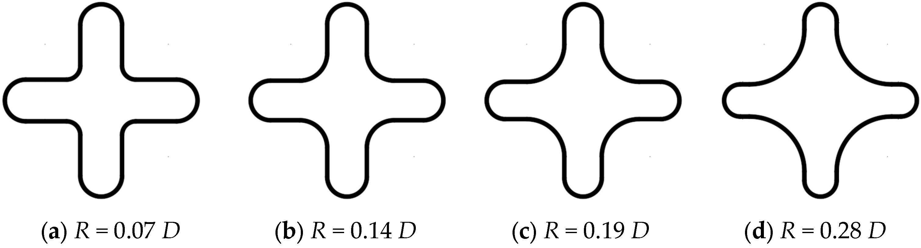
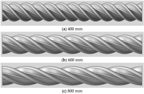
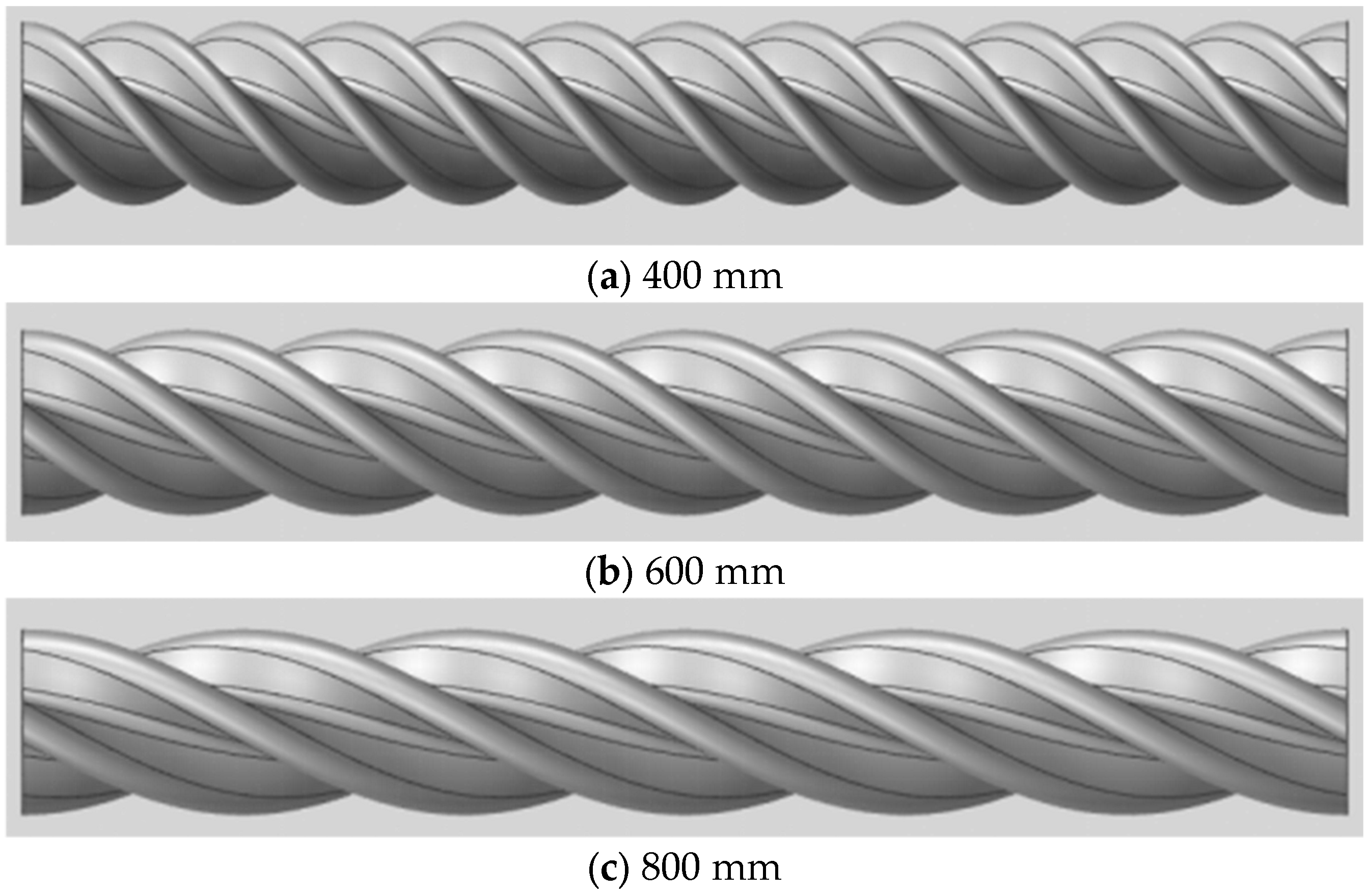
To investigate the effects of geometric structure on flow and heat transfer characteristics of HCF rods, this paper designs four geometric cross-section configurations and three helical pitch configurations. Based on the premise of constant fuel pellet volume, the four geometric cross-section designs modify the cross-sectional shape by adjusting the concave arc dimension R and convex arc dimension r, with a uniform helical pitch of 600 mm and a twist angle of 720°, as shown in Figure 2. To maintain the geometric periodicity of the fuel, the three helical pitch designs are 400 mm, 600 mm, and 800 mm, corresponding to twist angles of 1080°, 720°, and 540°, respectively. All three designs adopt the geometric cross-section with R = 0.19 D, as shown in Figure 3. The boundary conditions for the computational domain in this study are set as follows. A velocity inlet boundary condition is adopted at the inlet, where the inlet flow velocity and fluid temperature are specified to simulate the actual injection state of the reactor coolant. The outlet is set as a pressure outlet boundary condition. For the interface between the fuel rod solid domain and the fluid domain, a coupled boundary condition is employed, enabling real-time mutual coupling and bidirectional transfer of the temperature field and heat flux between the two wall surfaces. This ensures thermal continuity at the solid–liquid interface and accurately reflects the actual heat transfer process from the fuel rod to the coolant. The outer wall of the fluid domain is set as a no-slip adiabatic wall to simulate the thermal insulation constraint of the assembly box wall on the external environment, eliminating the interference of boundary effects on the flow field and temperature field in the rod bundle region. Referring to the operating conditions of the Russian PIK test reactor, The same boundary conditions are adopted for different geometric structures, as shown in Table 1.
Figure 2.
Fuel geometric cross-section design.
Figure 3.
Schematic diagram of helical pitch design.
Table 1.
Boundary conditions.
2.2. Model and Mesh Verification
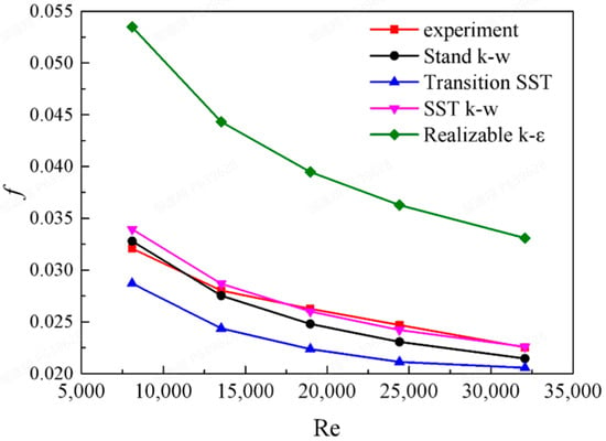
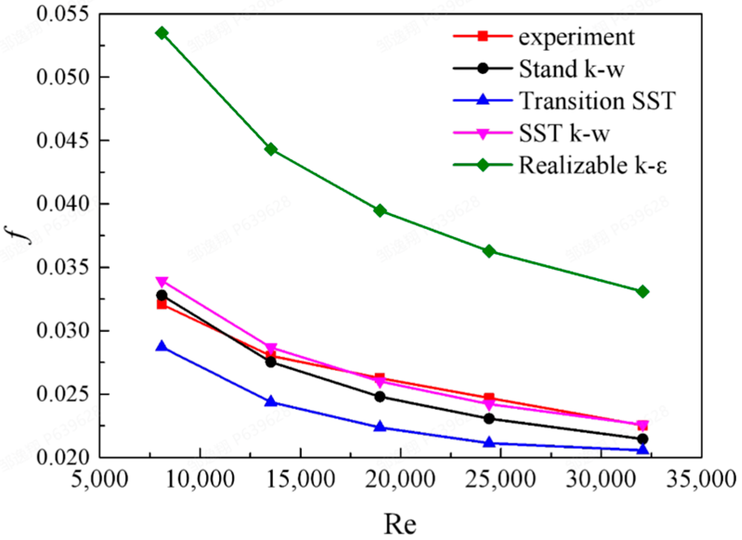
The turbulence model significantly affects CFD flow and heat transfer simulations. To investigate its impact, numerical simulations were performed using the Standard k-ω, Transition SST, SST k-ω, and Realizable k-ε models. These simulations were based on the data and geometric model from the MIT HCF rod bundle pressure drop experiment. Comparative analyses were conducted at five Reynolds numbers (Re = 8090, 13,530, 18,970, 24,410, and 32,070), with the results shown in Figure 4. The resistance coefficient f is defined as:
where is the friction factor, is the pressure drop across the rod bundle channel (Pa), is the fluid density in the rod bundle channel (kg·m−3), is the total length of the rod bundle channel (m), is the hydraulic diameter (m), and is the flow velocity (m·s−1).
Figure 4.
Turbulence model validation.
The HCF rod bundle resistance coefficient decreases with increasing Reynolds number, and all four models follow the experimental trend. The average relative errors of the Standard k-ω, Transition SST, SST k-ω, and Realizable k-ε models compared to experimental values are 4.16%, 12.31%, 2.28%, and 53.81%, respectively. The SST k-ω model shows the best agreement with the experimental results; therefore, this model is adopted for subsequent numerical simulations.
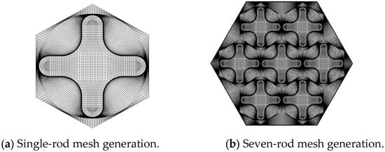
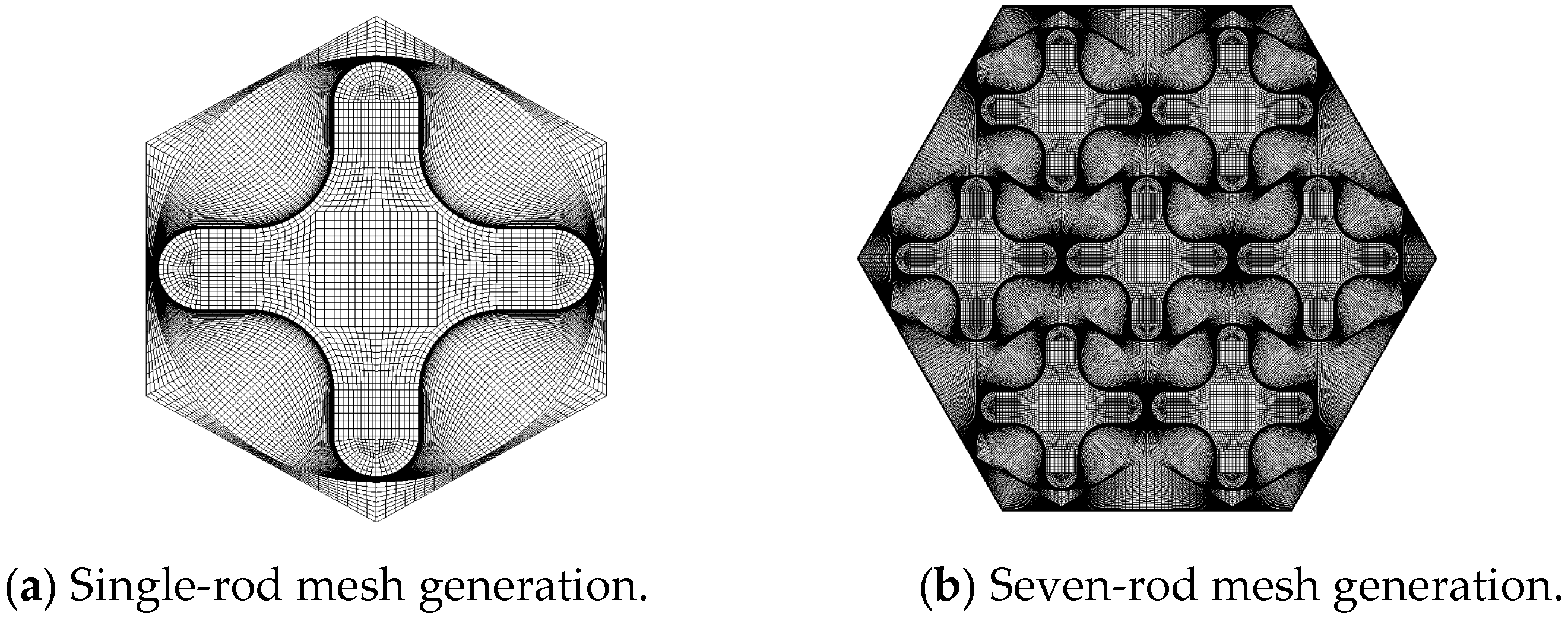
This study adopts the multi-block meshing method developed by KAERI and implements structured grid generation for the helical cruciform fuel assembly using ICEM. The computational domain comprises the fuel pellet region, fuel cladding region, near-wall fluid region, and outer fluid region. The fuel pellet region, fuel cladding region, and near-wall fluid region are generated by rotational extrusion of two-dimensional grids, while the outer fluid region mesh is obtained through two-dimensional grid extrusion. Five boundary layer grids are set in the near-wall fluid region contacting the fuel cladding, with a first-layer grid height of 0.001 mm and a near-wall y+ value of approximately 1, satisfying the near-wall treatment requirements of the turbulence model. In this study, the overall mesh generation for the compact fuel rod bundle assembly is divided into multiple single-rod hexagonal computational domain meshes and outer fluid domain meshes; the interfaces between meshes are handled through node merging to achieve grid stitching across different regions. Through this multi-block partitioning approach, component-level computational domains for 7-rod, 19-rod, and 37-rod assemblies can be assembled based on the grid partitioning of single-rod computational domains, significantly reducing the meshing workload for helical cruciform fuel. The multi-block seven-rod bundle mesh generation is shown in Figure 5.
Figure 5.
Mesh generation of the compact multi-block seven-rod helical cruciform fuel assembly.
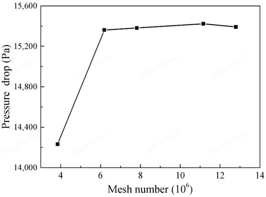
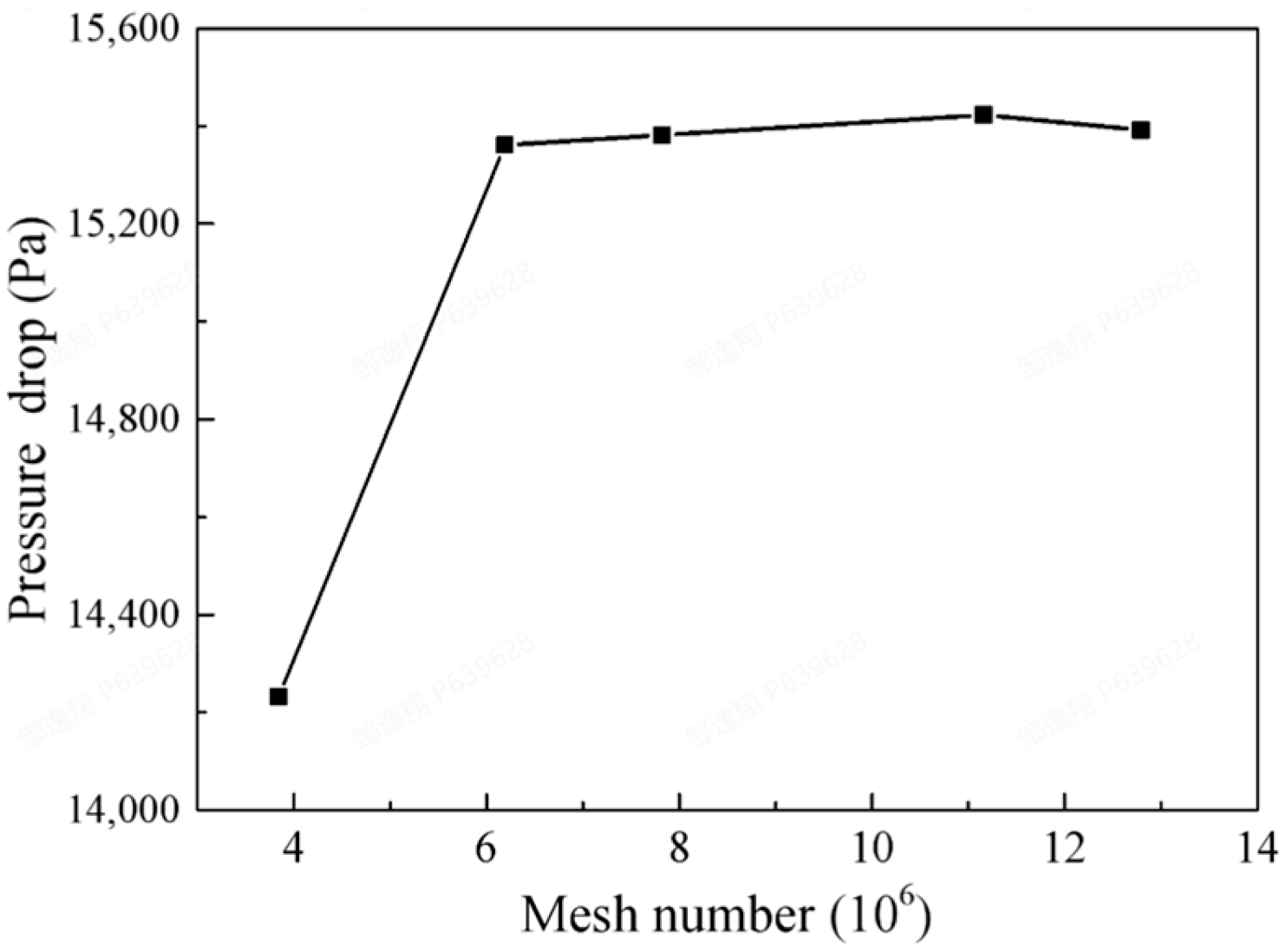
Five mesh schemes (3.84 million, 6.19 million, 7.82 million, 11.16 million, and 12.79 million cells) were employed for numerical simulation. Mesh independence was verified by comparing the pressure drop between inlet and outlet, as shown in Figure 6. The results indicate that the pressure drop reaches its peak with 11.16 million cells, with deviations below 1% compared to both 7.82 million and 12.79 million cells; therefore, 11.16 million cells were selected for subsequent calculations.
Figure 6.
Mesh independence verification.
3. Results and Analysis
3.1. Geometric Cross-Section Analysis
Since the cross-flow field and temperature field of the HCF rod bundle channel reach a steady state at a 90° twist angle, considering the geometric periodicity in the flow direction, the computational results in this paper are presented at cross-sections with a twist angle of 180°. Under identical operating conditions, this section investigates the effects of different geometric cross-section dimensions on the thermal–hydraulic performance of the HCF rod bundle, including pressure drop, cross-flow, temperature field, and heat transfer coefficient. Table 2 presents the comparison of pressure drop results for HCF with different geometric cross-section dimensions at a 600 mm helical pitch. As the concave arc dimension R increases, the pressure drop of HCF shows a decreasing trend, with a 6.36% reduction for R = 0.28 D compared to R = 0.07 D.
Table 2.
Effect of geometric cross-section on pressure drop.
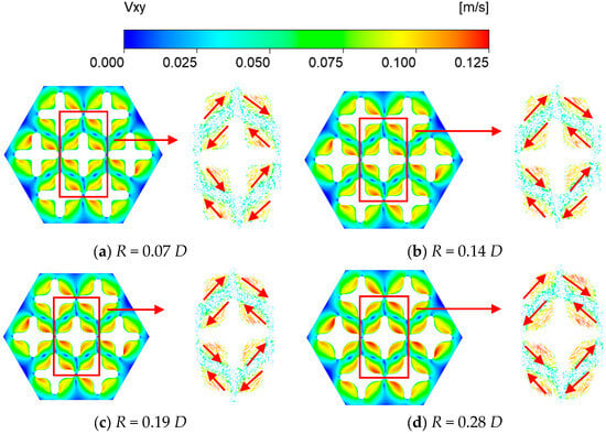
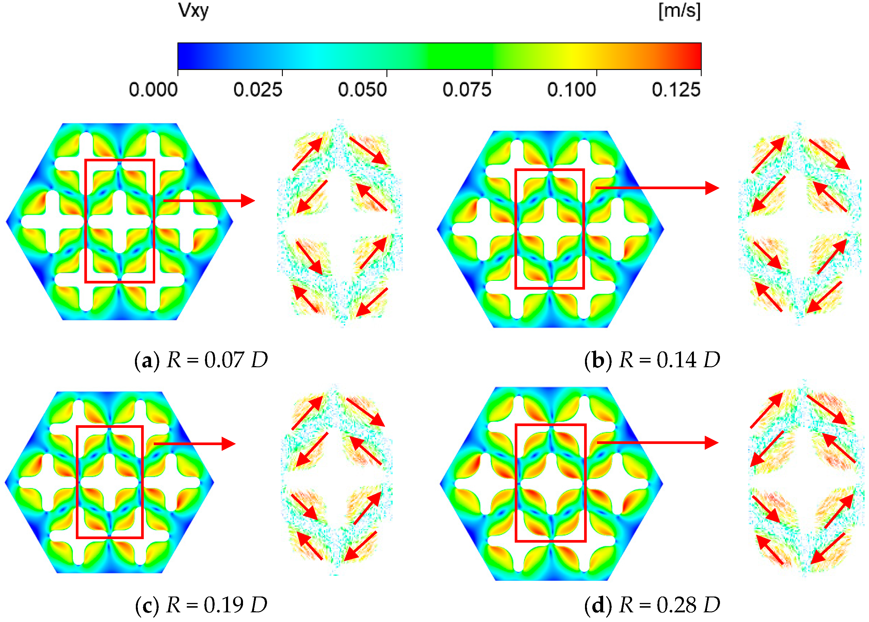
Figure 7 presents the cross-flow distribution contours and vector diagrams for rod bundles with different cross-section dimensions at a twist angle of 180°. The HCF rods twist counterclockwise, generating cross-flow on the rod surface that propagates along the twist direction. The cross-flow is primarily concentrated near the concave arc of the HCF rods, with the maximum cross-flow intensity occurring on the side of the HCF rod blade corresponding to the twist direction. The lowest average cross-flow velocity is observed at the junction positions between HCF rods, with a mean value of 0.01 m/s. This is attributed to the fact that at these junction positions, the cross-flow magnitudes from the concave arcs on both sides are comparable but opposite in direction, resulting in counteracting effects and forming a low-intensity valley region. Table 3 compares the maximum and average cross-flow velocities for rod bundles with different cross-section dimensions at a twist angle of 180°. As the concave arc radius R increases, the average cross-flow intensity of HCF shows an enhancing trend.
Figure 7.
Cross-flow distribution of HCF with different cross-section dimensions (twist angle: 180°).
Table 3.
Effect of geometric cross-section on cross-flow (twist angle: 180°).
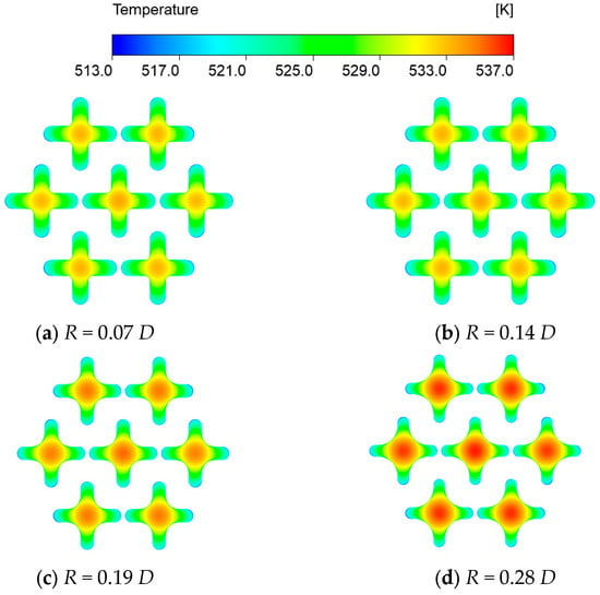
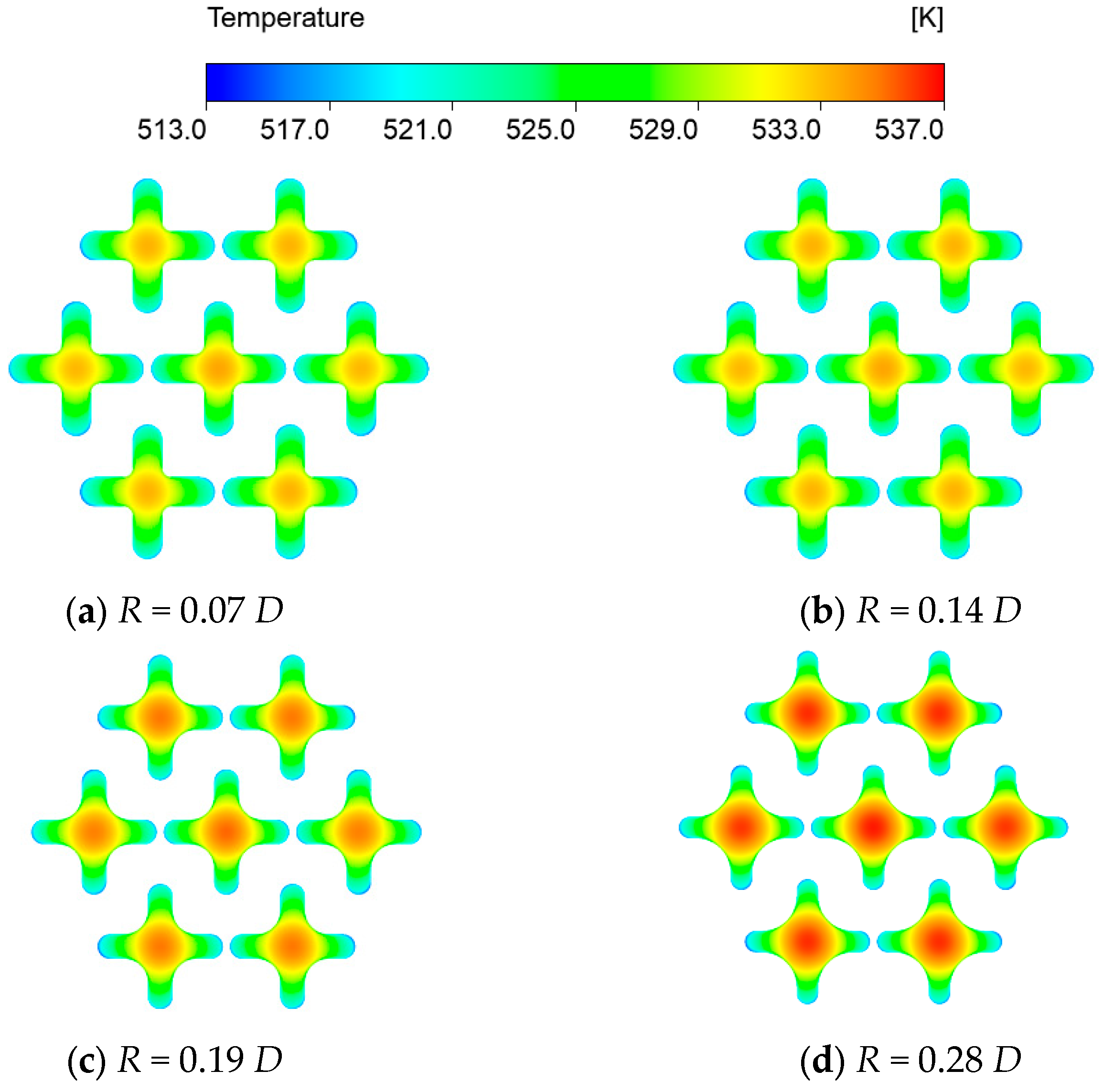
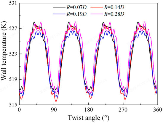
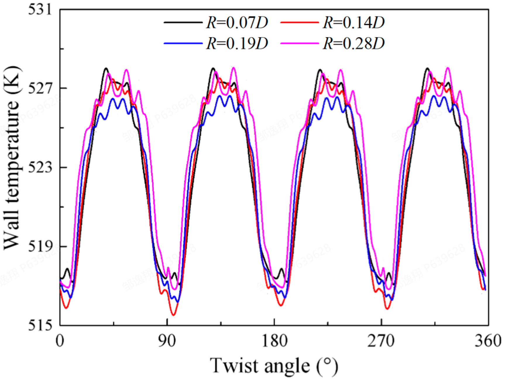
Figure 8 presents the solid temperature distribution contours of the HCF rod bundle with different cross-section dimensions at a twist angle of 180°. As the concave arc dimension R increases, the average temperature in the solid domain of the HCF rod bundle rises. This is attributed to the fact that with constant internal heat source volume, the heat transfer area of the HCF rod decreases with the increasing concave arc R, resulting in weakened heat transfer capability on the fuel rod surface and elevated solid temperature. Figure 9 shows the circumferential wall temperature distribution of the central rod with different cross-section dimensions at a twist angle of 180°. The maximum circumferential wall temperature of the HCF rod occurs at the concave arc position, while the minimum wall temperature appears at the convex arc apex, with a maximum temperature difference of approximately 12.4 K. As the concave arc dimension R increases, the maximum and minimum fuel wall temperatures show minor variations; however, the geometric expansion of the concave arc region leads to an enlarged peak temperature region on the fuel wall surface, thereby raising the average wall temperature.
Figure 8.
Temperature field distribution with different cross-section dimensions (twist angle: 180°).
Figure 9.
Circumferential wall temperature distribution of the central rod with different cross-section dimensions (twist angle: 180°).
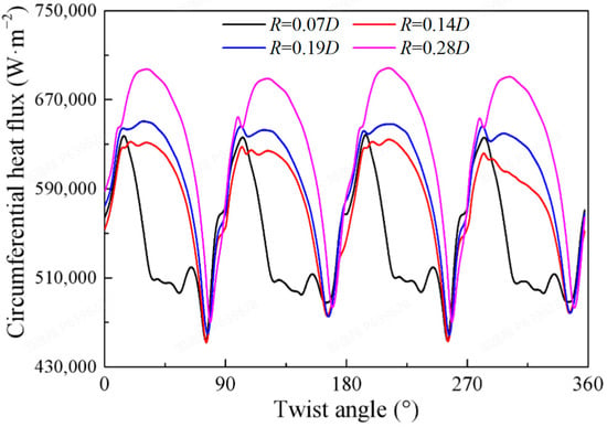
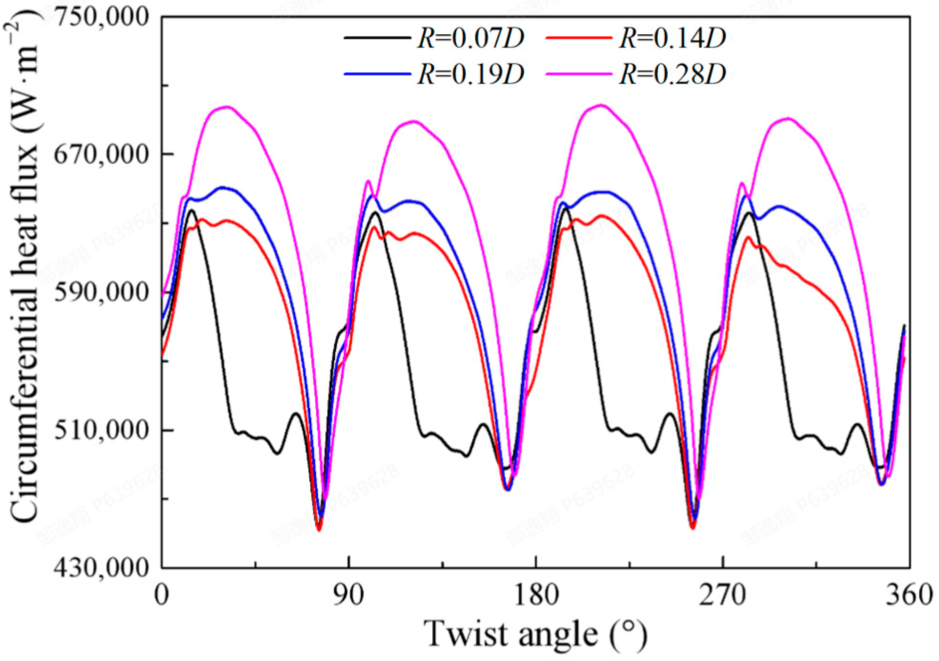
Figure 10 presents the circumferential heat flux distribution of the central rod with different cross-section dimensions. It can be observed that the heat flux of the HCF rod exhibits significant non-uniform distribution, and this non-uniformity intensifies with the increasing concave arc dimension R. Taking the 0.28 D dimension at a 90° twist angle as an example, the ratio of maximum to minimum heat flux reaches 2.36. The heat flux peak is located in the concave arc region of the fuel, while the minimum value occurs near the convex arc. In the HCF rod bundle, the concave arc region exhibits high wall temperature and strong cross-flow mixing near the wall, resulting in enhanced convective heat transfer performance; conversely, the convex arc region shows low wall temperature and weak cross-flow mixing, leading to inferior convective heat transfer performance, which causes the circumferential non-uniform distribution of heat flux. For the R = 0.07 D dimension, the heat flux in the entire concave arc region of the HCF bundle is significantly lower than that of other dimensions. This is attributed to the significantly weakened cross-flow mixing in the near-wall region of the concave arc at this dimension, resulting in degraded convective heat transfer capability near the concave arc and forming a heat flux valley region. Table 4 presents the comparison of maximum and average heat flux on the HCF rod wall surface with different cross-section dimensions. As the concave arc dimension increases, the heat flux of the fuel is significantly enhanced, with the maximum wall heat flux and average heat flux increasing by 12.45% for R = 0.28 D compared to R = 0.07 D. Under constant linear power density, the heat transfer area of HCF decreases with the increasing concave arc dimension R, resulting in a significant increase in the average heat flux of the rod bundle.
Figure 10.
Circumferential heat flux distribution of the central rod with different cross-section dimensions (twist angle: 180°).
Table 4.
Effect of geometric cross-section on cross-flow.
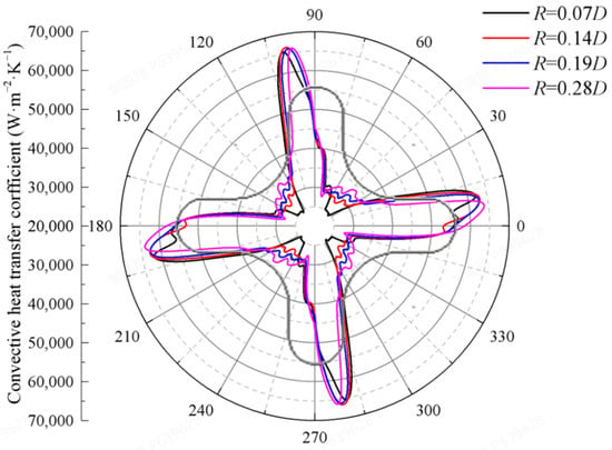
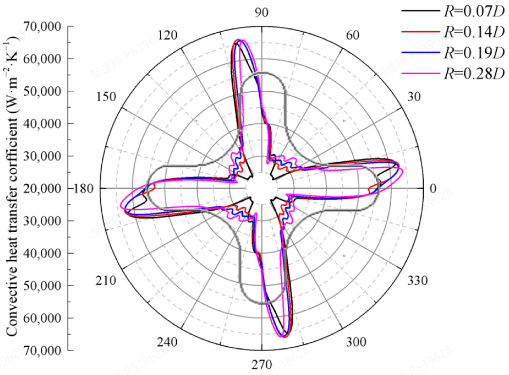
Figure 11 presents the circumferential distribution of the convective heat transfer coefficient on the central rod wall surface at the 180° cross-section. As shown, the convective heat transfer coefficient distributions of helical cruciform fuel under different cross-section dimension parameters all exhibit pronounced non-uniform characteristics, which are closely associated with the periodically transverse flow field structure induced by the helical geometry, reflecting the significant variation in coolant lateral sweeping intensity at different circumferential positions. Taking the R = 0.19 D case as a quantitative example, the maximum heat transfer coefficient on the central rod surface reaches 66,897 W·m−2·K−1, while the minimum value is merely 28,395 W·m−2·K−1, yielding a ratio of maximum to minimum heat transfer coefficient of 2.36, indicating extremely poor circumferential heat transfer uniformity for this dimension. Under the R = 0.07 D parameter, the circumferential heat transfer performance in the concave arc region deteriorates more severely, with the minimum heat transfer coefficient dropping to 24,076 W·m−2·K−1, which is 15.21% lower than that of the R = 0.19 D case, demonstrating the significant detrimental effect of small concave arc dimensions on local heat transfer. The underlying mechanism for this phenomenon is as follows: at R = 0.07 D, the excessively small concave arc dimension restricts the helical geometry’s guiding effect on transverse flow, resulting in flow stagnation zones or low-velocity recirculation regions on the blade leeward side and in the concave arc area; the emergence of these transverse flow depression zones substantially weakens the convective heat transfer capability in this region. Meanwhile, due to the coupling relationship between the heat transfer coefficient and wall heat flux, the extremely low heat transfer coefficient at this location also causes the wall heat flux to be significantly lower than that of other dimension schemes, creating a dual deterioration in heat transfer performance. Furthermore, comparing different cross-section dimensions reveals that the circumferential heat transfer non-uniformity is somewhat alleviated under the R = 0.28 D condition, indicating that moderately increasing the concave arc dimension can improve circumferential heat transfer uniformity to a certain extent by enhancing overall transverse flow mixing and reducing the extent of local flow stagnation zones, which provides an important optimization direction for the thermal–hydraulic safety design of fuel assemblies. This finding reveals the regulatory mechanism of the concave arc dimension R on circumferential heat transfer non-uniformity: excessively small R values exacerbate flow stagnation effects in the concave arc region and expand the scope of heat transfer depression zones, not only reducing local heat transfer coefficients but also potentially leading to excessively high wall temperatures, posing a potential threat to the thermal safety of fuel elements. Therefore, in geometric optimization design, the concave arc dimension must be sufficient to maintain basic transverse flow mixing levels to avoid severe local heat transfer deterioration.
Figure 11.
Convective heat transfer coefficient distribution of the central rod with different cross-section dimensions (twist angle: 180°).
3.2. Helical Pitch Analysis
Since HCF rod bundles with different helical pitches have different twist angles at the same cross-section height, identical flow channel flow fields and temperature fields can only be obtained at the inlet and outlet positions. Therefore, the analysis of flow and temperature fields for different helical pitches is primarily based on cross-sections at the component outlet position. Table 5 presents the comparison of inlet–outlet pressure drop for different helical pitches. As the helical pitch increases, the inlet–outlet pressure drop decreases, with a 2.77% reduction for the 800 mm pitch compared to the 400 mm pitch.
Table 5.
Effect of helical pitch on pressure drop.
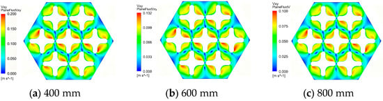
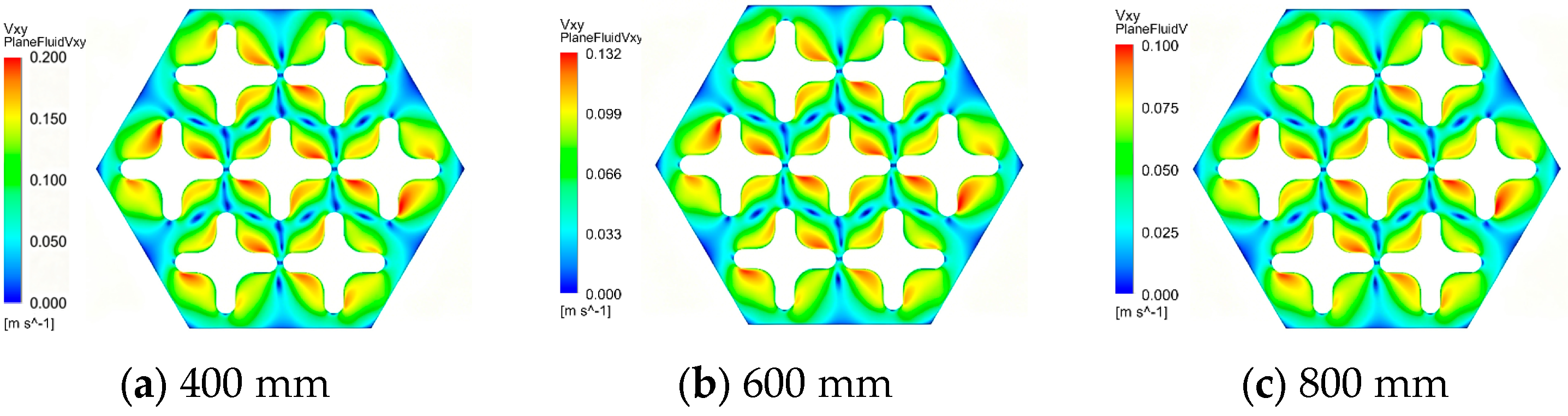
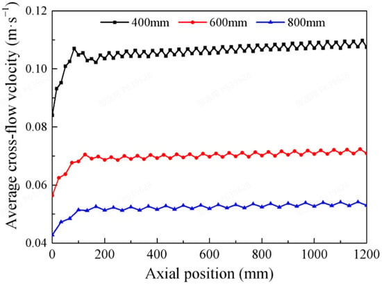
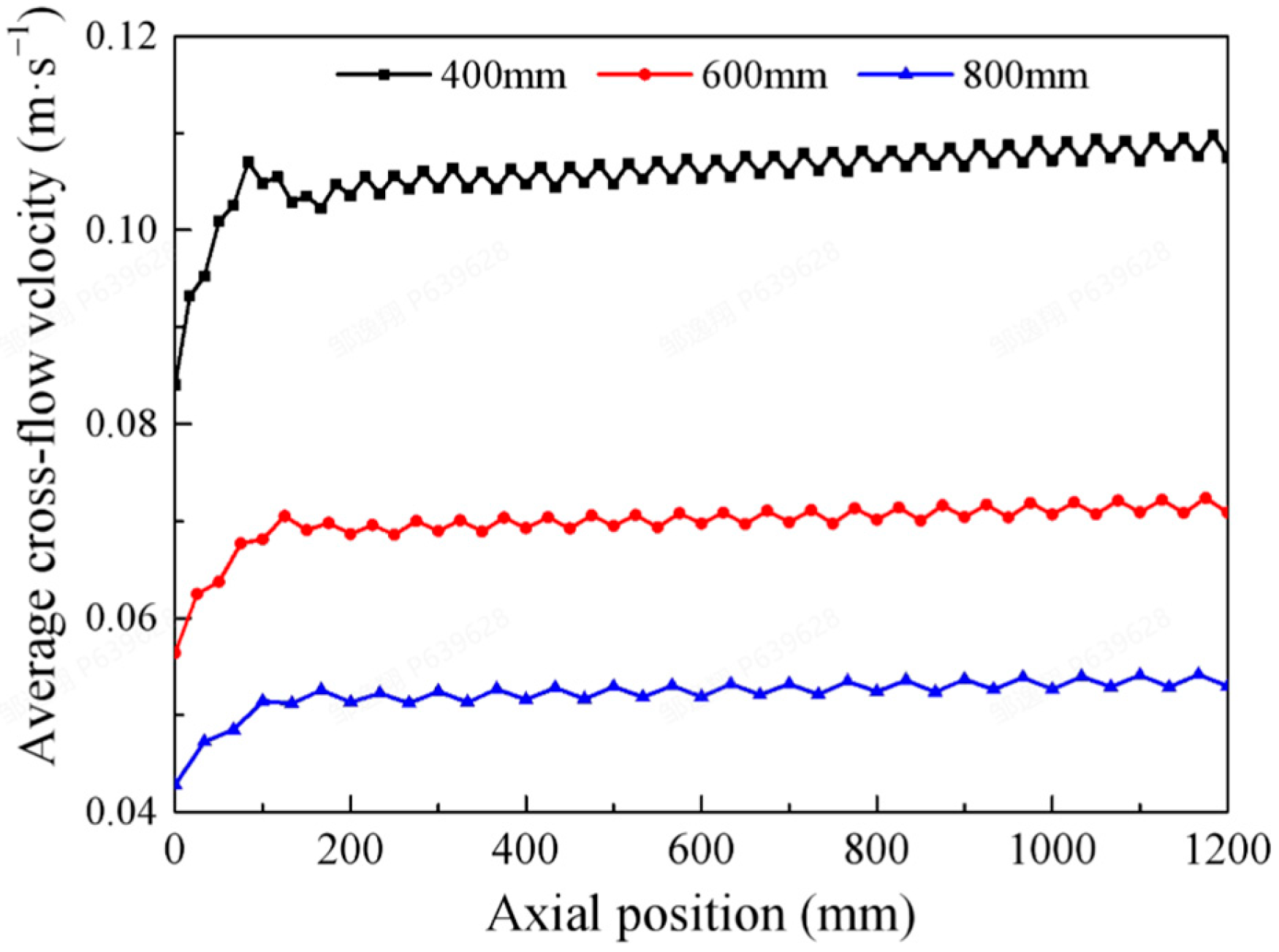
Figure 12 and Figure 13 present the cross-flow intensity distribution contours at the outlet position and the variation in average cross-flow intensity along the flow path for different helical pitches. It can be observed that the cross-flow intensity in the flow field decreases significantly with increasing fuel helical pitch. Under the operating condition with an inlet velocity of 4 m/s, the maximum cross-flow intensity is approximately 0.203 m/s for the 400 mm pitch, while it is only 0.0964 m/s for the 800 mm pitch. On average, the cross-flow intensity generated in the downstream region of the rod bundle for the 400 mm pitch is approximately 0.105 m/s, which is 103.45% higher than that of the 800 mm pitch. Meanwhile, due to the variation in helical pitch, the geometric period of HCF rods changes, resulting in more rapid fluctuations of cross-flow intensity over shorter distances for the 400 mm pitch.
Figure 12.
Cross-flow distribution of HCF with different helical pitches (outlet cross-section).
Figure 13.
Ariation of average cross-flow velocity along the flow path.
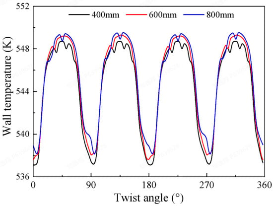
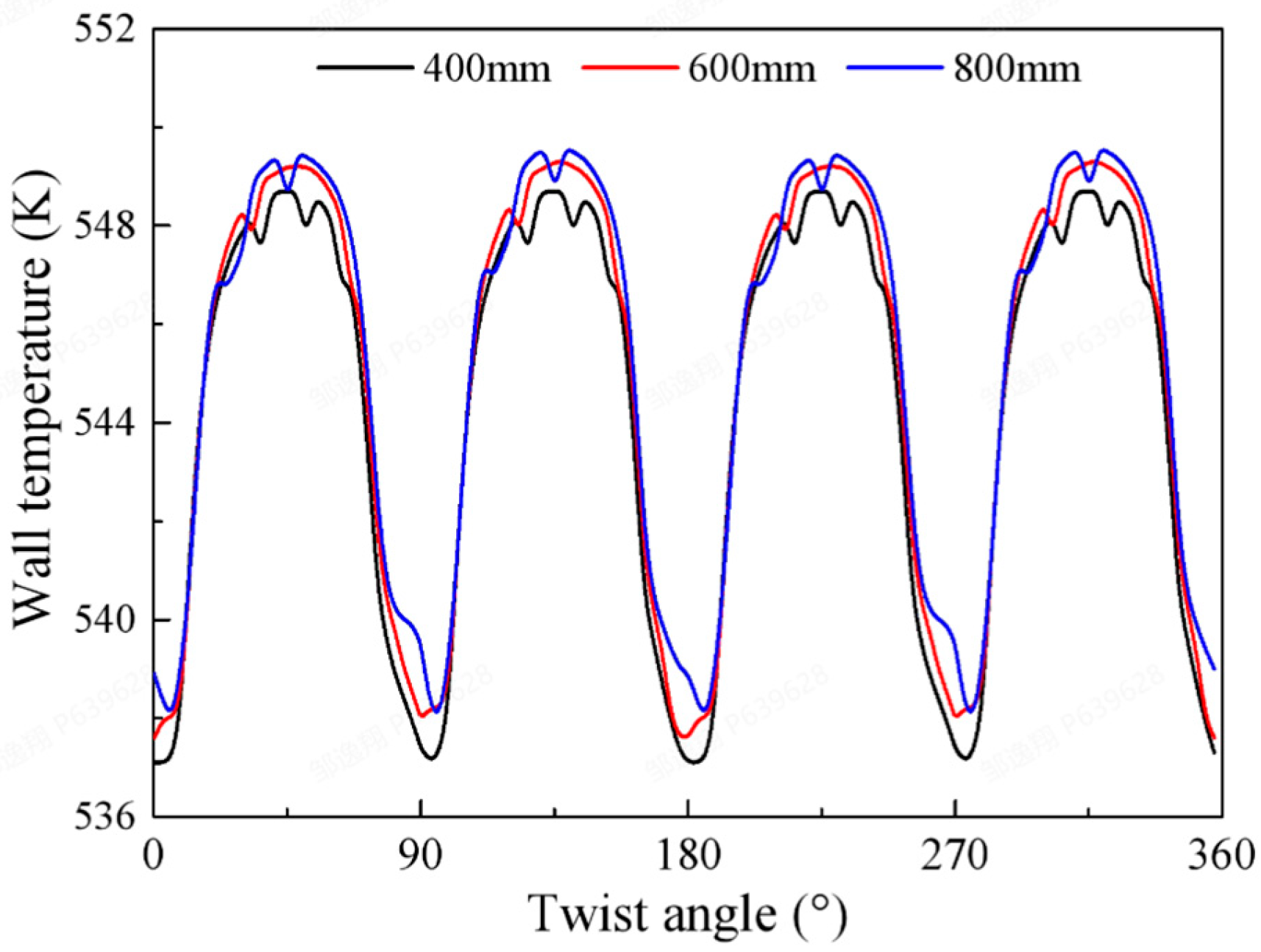
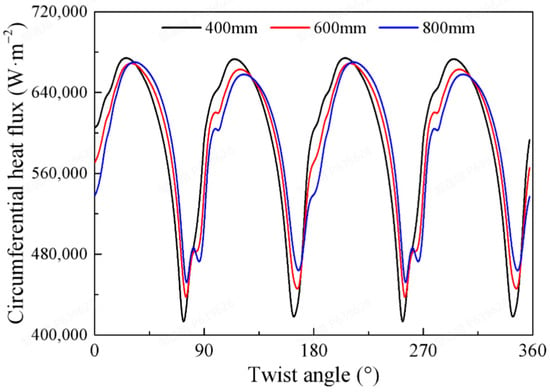
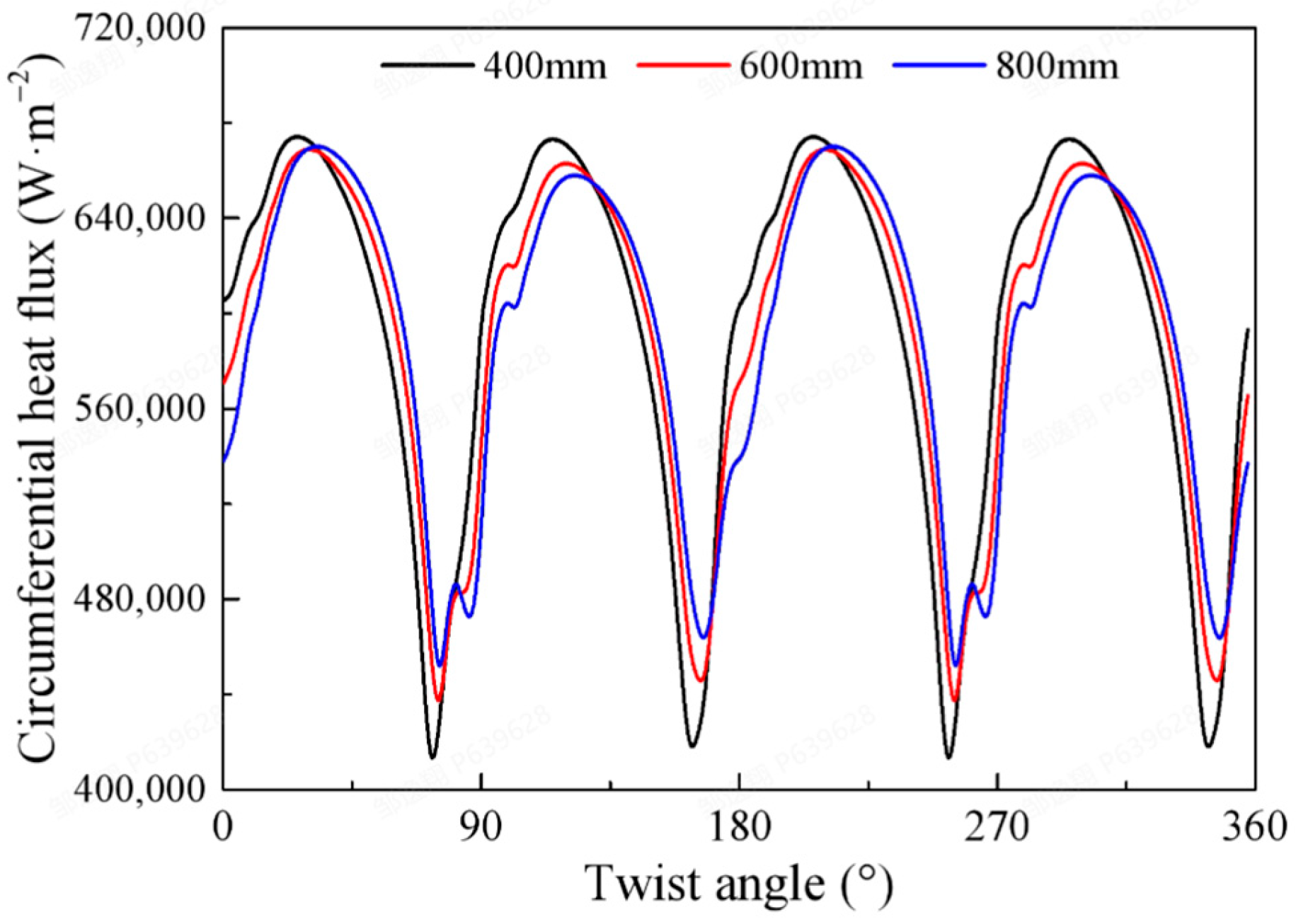
Figure 14 shows the circumferential wall temperature distribution of the central rod at the outlet cross-section for different helical pitches. The trends of circumferential wall temperature distribution are consistent across different pitches. As the helical pitch increases, the wall temperature rises slightly, with the temperature difference between the maximum and minimum circumferential temperatures remaining approximately 11.6 K for all pitches. The helical pitch does not exhibit a significant effect on the circumferential wall temperature distribution of the fuel rods. Figure 15 presents the circumferential heat flux distribution of the central rod at the outlet cross-section for different helical pitches. The trends of circumferential heat flux distribution are similar across different pitches. The peak values of circumferential heat flux distribution are all located in the concave region of HCF, while the valley regions appear in the convex area. The maximum circumferential heat flux values show minor differences among different pitches; however, the 400 mm pitch exhibits lower heat flux in the valley regions, with its minimum heat flux being 8.02% lower than that of the 800 mm pitch. As the helical pitch decreases, the circumferential heat flux distribution of the HCF rod becomes more non-uniform.
Figure 14.
Circumferential wall temperature distribution of the central rod with different helical pitches.
Figure 15.
Circumferential wall heat flux distribution of the central rod with different helical pitches.
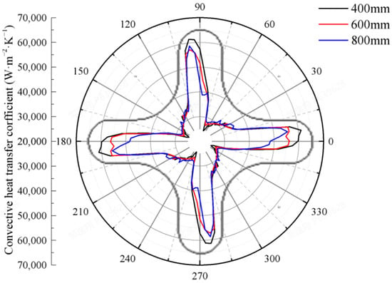
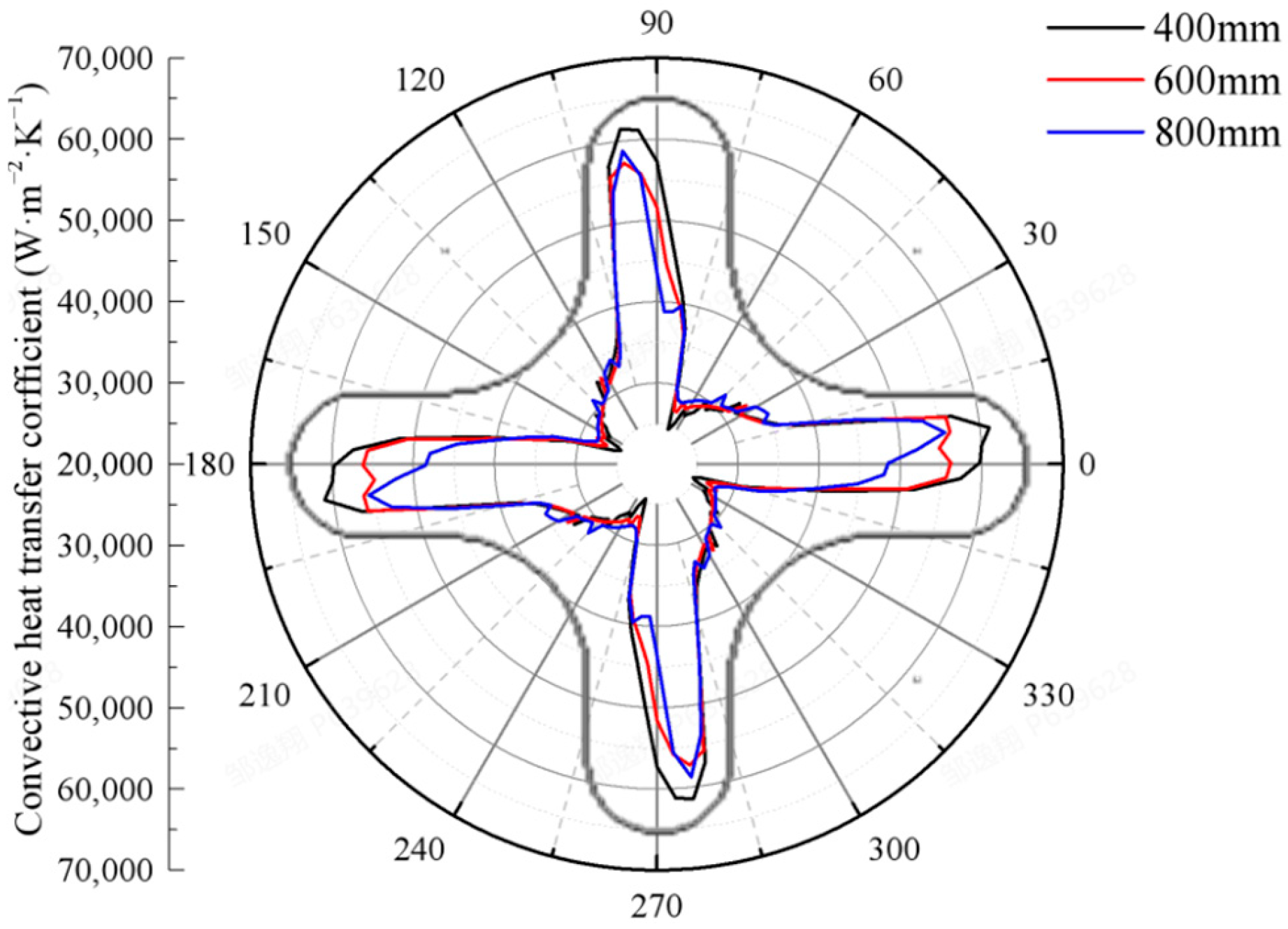
Figure 16 presents the circumferential distribution of the heat transfer coefficient for the central rod at the outlet cross-section under different helical pitches. At the outlet cross-section, the heat transfer coefficient for the 400 mm pitch is 2.75% higher than that for the 800 mm pitch, indicating that a smaller pitch effectively enhances the local convective heat transfer capability on the windward side through intensified transverse flow mixing. However, this enhancement effect is primarily concentrated in the high heat transfer region on the windward side, with limited improvement for the low heat transfer region on the leeward side; overall, the circumferential heat transfer non-uniformity is not fundamentally alleviated. In summary, reducing the pitch can achieve local heat transfer enhancement, but may also exacerbate the distribution difference in circumferential heat flux. In engineering design, it is necessary to balance the relationship between local heat transfer enhancement and overall thermal load uniformity in conjunction with specific thermal–hydraulic safety margin requirements, in order to determine the optimal pitch design parameter.
Figure 16.
Convective heat transfer coefficient distribution of the central rod with different helical pitches (outlet cross-section).
4. Discussion
This study presents numerical simulations of single-phase convective heat transfer in a 7-rod compact helical cruciform fuel (HCF) assembly with systematically varied structural parameters. The helical geometry induces periodic swirling flow that generates distinct momentum and energy transport patterns compared to conventional cylindrical rods. By analyzing pressure drop, cross-flow velocity fields, temperature distributions, and wall heat flux under various geometric cross-sections and helical pitches, this work examines the interplay between heat transfer area and flow mixing intensity that governs HCF thermal–hydraulic performance.
- (1)
- Geometric cross-section effects: As the concave arc dimension R increases, the flow recirculation zone near the concave surface diminishes, reducing flow resistance and thereby decreasing the inlet–outlet pressure drop. Simultaneously, the enhanced cross-flow mixing promotes thermal boundary layer disruption, improving convective heat transfer efficiency. However, a trade-off between hydraulic and thermal performance emerges: the reduced heat transfer area leads to higher average wall heat flux and a corresponding rise in wall temperature, which may affect fuel thermal margins under high-power conditions.
- (2)
- Optimal R selection: While reducing R enlarges the heat transfer area and reduces average heat flux, a critical threshold exists at R = 0.07 D where the concave arc region experiences insufficient cross-flow mixing, forming a stagnant zone that locally degrades heat transfer performance compared to R = 0.14 D. This phenomenon reflects the competition between helical-induced centrifugal force and viscous dissipation in narrow gaps. Consequently, R = 0.14 D represents a balanced compromise that maintains adequate flow mixing while preserving substantial heat transfer area.
- (3)
- Helical pitch effects: Increasing pitch L reduces the helical curvature, weakening the centrifugal pumping effect that drives cross-flow circulation. The cross-flow intensity decreases substantially, particularly degrading the heat transfer performance in the inner concave arc regions where transverse flow is most effective. With fixed internal heat generation, the total wall heat flux remains constant; however, the local heat flux redistributes circumferentially. As the cooling capability at the concave arcs weakens, the local heat flux in these regions decreases, while the relative heat flux proportion at the outer convex portions increases. Consequently, the circumferential difference in wall heat flux between the concave and convex regions diminishes, resulting in a more uniform circumferential heat flux distribution. The relatively minor wall temperature variation indicates that the weakened cross-flow primarily alters the circumferential heat flux partitioning rather than the overall thermal energy removal.
Design recommendations: Based on the identified physical mechanisms, R = 0.14 D is recommended as it avoids the insufficient mixing zone near the concave arc while maintaining substantial heat transfer area. For helical pitch, a smaller L is preferred within manufacturing constraints, as stronger cross-flow mixing enhances thermal boundary layer renewal and improves overall heat transfer uniformity. However, this comes at the cost of increased circumferential heat flux non-uniformity, which may induce higher thermal stresses in the fuel cladding. These findings provide a physical basis for HCF geometric optimization in compact reactors and establish a foundation for extending to two-phase conditions where bubble dynamics and flow mixing interact.
Author Contributions
Conceptualization, C.W.; Validation, Y.M. and C.W.; Formal analysis, Y.Z. and J.Y.; Data curation, Q.L.; Writing—original draft, Y.Z.; Writing—review & editing, Y.Z.; Visualization, Y.Z., Y.M. and J.Y.; Supervision, Y.M., C.W., Q.L. and J.S. All authors have read and agreed to the published version of the manuscript.
Funding
This research received no external funding.
Data Availability Statement
The data presented in this study are available on request from the corresponding author.
Conflicts of Interest
Authors Yixiang Zou, Yue Ma, Jingwen Yan, Chang’e Wu, and Qifeng Lv were employed by the company China Nuclear Power Technology Research Institute Co., Ltd. The remaining authors declare that the research was conducted in the absence of any commercial or financial relationships that could be construed as a potential conflict of interest.
Abbreviation
The following abbreviation is used in this manuscript:
| HCF | Helical cruciform fuel |
References
- Xiao, Y.; Fu, J.; Zhang, Q.; Zhao, H.; Gu, H. Development of a flow sweeping mixing model for helical fuel rod bundles. Ann. Nucl. Energy 2021, 160, 108428. [Google Scholar] [CrossRef] [Scilit]
- Zhao, H.; Zhang, Q.; Gu, H.; Xiao, Y.; Liu, M. CFD investigation on thermal-hydraulic characteristics of a helical cruciform fuel bundle. Prog. Nucl. Energy 2022, 148, 104228. [Google Scholar] [CrossRef] [Scilit]
- Chukhlov, A.G.; Smirnov, V.P.; Afonin, S.Y. Application of periodic boundary conditions to thermal-hydraulic calculation of fuel assemblies with finned fuel rods. Therm. Eng. 2012, 59, 44–50. [Google Scholar] [CrossRef] [Scilit]
- Shirvan, K. Numerical investigation of the boiling crisis for helical cruciform-shaped rods at high pressures. Int. J. Multiph. Flow 2016, 83, 51–61. [Google Scholar] [CrossRef] [Scilit]
- Shirvan, K.; Kazimi, M.S. Three dimensional considerations in thermal-hydraulics of helical cruciform fuel rods for LWR power uprates. Nucl. Eng. Des. 2014, 270, 259–272. [Google Scholar] [CrossRef] [Scilit]
- Cong, T.; Xiao, Y.; Wang, B.; Gu, H. Numerical study on the boiling heat transfer and critical heat flux in a simplified fuel assembly with 2 × 2 helical cruciform rods. Prog. Nucl. Energy 2022, 145, 104111. [Google Scholar] [CrossRef] [Scilit]
- Cong, T.; Zhang, R.; Wang, B.; Xiao, Y.; Gu, H. Single-phase flow in helical cruciform fuel assembly with conjugate heat transfer. Prog. Nucl. Energy 2022, 147, 104199. [Google Scholar] [CrossRef] [Scilit]
- Palumbo, L.P. Simulated heat transfer out of a metallic cruciform CANDU fuel element. McMaster J. Eng. Phys. 2018, 2. [Google Scholar]
- Cai, W.; Huang, Z.; Zhang, W.; Meng, X.; Sun, J. Numerical investigation on subcooled boiling and CHF characteristics in 3 × 3 petal-shaped fuel rod bundle channel under cosine heating condition. Ann. Nucl. Energy 2024, 206, 110660. [Google Scholar] [CrossRef] [Scilit]
- Du, L.; Jiang, Z.; Zhang, W.; Sun, J.; Jin, G.; Cai, W. Numerical investigation on characteristics of the onset of nucleate boiling in petal-shape fuel rod bundle assembly. Ann. Nucl. Energy 2024, 195, 110189. [Google Scholar] [CrossRef] [Scilit]
- Conboy, T.M.; McKrell, T.J.; Kazimi, M.S. Experimental investigation of hydraulics and lateral mixing for helical-cruciform fuel rod assemblies. Nucl. Technol. 2013, 182, 259–273. [Google Scholar] [CrossRef] [Scilit]
- Conboy, T.M. Thermal-Hydraulic Analysis of Cross-Shaped Spiral Fuel in High power Density BWRs. Doctoral Dissertation, Massachusetts Institute of Technology, Cambridge, MA, USA, 2007. Available online: http://hdl.handle.net/1721.1/41309 (accessed on 6 May 2026).
- Conboy, T.M.; McKrell, T.J.; Kazimi, M.S. Assessment of Helical-Cruciform Fuel Rods for High Power Density; Massachusetts Institute of Technology, Center for Advanced Nuclear Energy Systems, Nuclear Fuel Cycle Program: Cambridge, MA, USA, 2010; Available online: http://hdl.handle.net/1721.1/75265 (accessed on 6 May 2026).
- Zhang, Q.; Liu, L.; Xiao, Y.; Fu, J.; Gu, H. Experimental study on the transverse mixing of 5 × 5 helical cruciform fuel assembly by wire mesh sensor. Ann. Nucl. Energy 2021, 164, 108582. [Google Scholar] [CrossRef] [Scilit]
- Totemeier, A.; Shapiro, N.; Vaidyanathan, S. LIGHTBRIDGE corporation advanced metallic fuel. In The 11th National Conference on Nuclear Science and Technology. Agenda and Abstracts; No. INIS-VN—002; International Atomic Energy Agency (IAEA): Vienna, Austria, 2015; p. 6. [Google Scholar]

Disclaimer/Publisher’s Note: The statements, opinions and data contained in all publications are solely those of the individual author(s) and contributor(s) and not of MDPI and/or the editor(s). MDPI and/or the editor(s) disclaim responsibility for any injury to people or property resulting from any ideas, methods, instructions or products referred to in the content. |
© 2026 by the authors. Licensee MDPI, Basel, Switzerland. This article is an open access article distributed under the terms and conditions of the Creative Commons Attribution (CC BY) license.