


Abstract
Additive manufacturing (AM) introduces surface roughness that is much larger than that in chemically etched printed circuit heat exchanger (PCHE) channels, limiting the applicability of established design correlation. In this study, four selective laser melting (SLM) 3D-printed stainless steel test sections were tested, namely two semicircular and two rounded-edge semicircular channels, at hydraulic diameters of 2 mm and 4 mm. Water was used as the test fluid in the experiment, with a Reynolds number ranging from 500 to 7000 and wall heat flux ranging from 20 to 90 kW/m2. Scanning electron microscopy image characterization shows significant material accumulation concentrated at the rounded edges of the as-built channels. The experimental results show that for the entire flow regime, the printed rounded edge increases the friction factor by approximately 9% for 2 mm and 4 mm channels. The filleting design would increase the effective hydraulic roughness in small-diameter AM channels. The SLM 3D-printed rougher channel has a lower transition Reynolds number and higher turbulent friction factors compared to the etching channel. The data were compared with existing smooth PCHE channel data and rough AM mini-channel correlation, and two empirical correlations were developed for SLM 3D-printed mini-channels for transition and turbulent regimes.
1. Introduction
Printed circuit heat exchangers contain thousands of mini-channels that pack a large heat transfer area into a compact volume, making them well suited for energy systems such as gas liquefaction plants and power cycle systems [1]. PCHEs are conventionally manufactured by chemically etching flow channels into flat metal plates, which are then joined by diffusion bonding [2,3]. The etching process yields channels with a nominally semicircular cross-section [1,4]. The wetted perimeter of a semicircular channel is approximately 1.16 times that of a circular channel at the same cross-sectional area, resulting in a larger heat transfer area at the same volumetric flow rate.
In practice, the profile deviates from the ideal: corners may become rounded [5], and diffusion bonding tends to reduce both channel depth and width, with hydraulic diameter deviations of 10% or more commonly reported. These dimensional changes can substantially increase the pressure drop [6]. Repeated thermal and pressure cycling in PCHE service can induce ratcheting deformation at channel corners [7]. From a fluid-dynamics perspective, filleting is expected to reduce velocity gradient fluctuations near the walls and promote a more uniform velocity profile across the cross-section [8]. Previous studies showed that at a constant heat transfer area, filleting lowers the friction factor while causing a modest reduction in Nusselt number [9]. The net effect on thermal–hydraulic performance therefore depends on the specific geometry and operating conditions.
Additive manufacturing provides a means to study these geometric effects in a controlled way. Unlike chemical etching and diffusion bonding where the effects of filleting and channel size are difficult to isolate, AM can reproduce target geometries with specified corner radii in filleting design, enabling systematic parametric comparisons. The semicircular cross-sectional shape is self-supporting during the build process, avoiding the ceiling sagging common in horizontally oriented circular channels in AM fabrication [10]. For vertically built AM semicircular channels, the flat surface helps reduce geometric distortion relative to curved surfaces. Xu et al. [11] fabricated vertically oriented circle, square, and rounded square shapes in low-resistance selective laser melting 3D-printed channels to compare their printing quality and friction factor. The square channels had better contoured fidelity than the circular channels, and the researchers concluded that geometric distortion becomes more serious when the curved boundary proportion increases. However, additively manufactured channels were substantially rougher than their chemically etched counterparts [10,12]. Surface irregularities are especially pronounced at small-radius fillets, where roughness increases as the corner radius decreases [13]. This special surface characteristic of additively manufactured channels may lead to a difference in friction factor performance trends, with the PCHE etching semicircular channels therefore requiring experimental investigation.
In comparisons of the friction factor in classical studies, the equivalent sand-grain roughness (ε) is often used in the calculation. However, the equivalent sand-grain roughness of AM channels is still unclear. Researchers often analyze surface roughness using average surface roughness (Ra) in metal 3D printing [14]. Lokanathan et al. [15] pointed out that the AM surface roughness is of a multiscale nature that differs from the uniform roughness in equivalent sand-grain roughness tests. The AM surface roughness is related to the size of powder particles and process instabilities due to complex reasons. The main effect is the adhesion of incomplete melting powder and spatter by complex interactions between gas flow during the AM process. Mandloi et al. [16] pointed out that for the same size of rough particles, different particle arrangements and surface textures can produce different pressure drop trends in turbulent flow regimes. The AM roughness characteristics are related to build orientation, the density of spatter deposits, particle size, particle amplitude, and wavelength arrangement. Stimpson et al. [17] proposed a correlation of ε/Dh as a function of Ra/Dh in direct metal laser sintering AM fabrication ribbed channels. The equivalent sand-grain roughness should be assumed as zero when Ra/Dh < 0.0028.
Yang [10] used direct metal laser sintering to fabricate compact heat exchangers in two build orientations and reported surface roughness of 10–30 μm for 1 mm hydraulic diameter channels. Of all geometries tested, the vertically built circular channels showed the lowest friction factor [10,14]. The vertically built printing orientation is commonly selected in metal AM as it has a smaller Ra compared to other printing orientations [14]. In Su et al. [18]’s study, two SLM 3D-printed triply periodic minimal-surface heat exchangers were compared to the PCHE. It was found that for the triply periodic minimal surface heat exchangers, the Diamond type has a smaller surface roughness (Ra = 5.122 µm) than the Gyroid type (Ra = 9.617 µm). Consistent with its lower roughness, the Diamond type exhibited a lower friction factor at the same Reynolds number. Both Diamond and Gyroid types are much larger (more than approximately 2.5 times) than the PCHE friction factor prediction models in laminar regimes. Da Silva et al. [12] fabricated an SLM heat exchanger core with a circular channel (Di = 2 mm). The average roughness was 12.21 μm, and it was demonstrated that the roughness could be significantly reduced by electropolishing and remelting post-treatment. Chen et al. [19] measured the friction factor and heat transfer in SLM 3D-printed circular mini-tubes and found that roughness shifts the laminar-to-turbulent transition to a lower Reynolds number.
Cao et al. [20] reported that for smooth tubes, the transition in friction factor is essentially independent of tube diameter but depends on relative roughness in rough tubes. This distinction is relevant here because the surface characteristics of 3D-printed channels differ substantially from those of chemically etched channels. Liu et al. [21] measured a root-mean-square roughness of only 0.473 μm in etched semicircular channels with Dh = 1.14 mm. Chu et al. [22] reported roughness below 5 μm in a straight-channel PCHE with Dh = 2.8 mm. Larger relative roughness shifts the turbulent friction factor trend upward [23]. Therefore, the flow transition behaviour observed in 3D-printed channels is not directly applicable to etched PCHE designs.
Everts and Mahomed [24] reported that rough channels can improve thermal–hydraulic performance in quasi-turbulent conditions, as reflected by a lower experimental f/j ratio result than in fully turbulent conditions. The earlier flow transition caused by high surface roughness means that additive manufacturing roughness (often regarded as a manufacturing defect) can play a passive role in enhancing heat transfer at medium Reynolds numbers.
According to the above-mentioned literature review, the interaction between corner filleting and the surface roughness of AM semicircular channels has not been considered in a previous study. This interaction varies depending on the flow conditions, and no systematic experimental investigation has been carried out to date. In this study, the effects were quantified by comparing 3D-printed semicircular and rounded-edge semicircular channels at two hydraulic diameters (2 mm and 4 mm). An investigation into how the hydraulic diameter governs the relative strength of each effect was also conducted. The main objectives of this research were as follows:
- Compare the friction factor of 3D-printed semicircular and rounded-edge semicircular channels at hydraulic diameters of 2 mm and 4 mm, under both isothermal and heating conditions.
- Assess the influence of relative roughness and rounded-edge channel geometry on the friction factor across laminar, transitional, and turbulent flow regimes.
- Verify the applicability of the well-established correlation with the experimental data.
- Develop the friction factor correlation specifically for the 3D-printed semicircular, rounded-edge semicircular, and circular channels.
2. Materials and Methods
In this study, an experimental setup with a series of customized 3D-printed channels was employed to evaluate pressure drop performance over a range of Reynolds numbers.
2.1. Experimental Setup
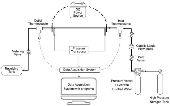
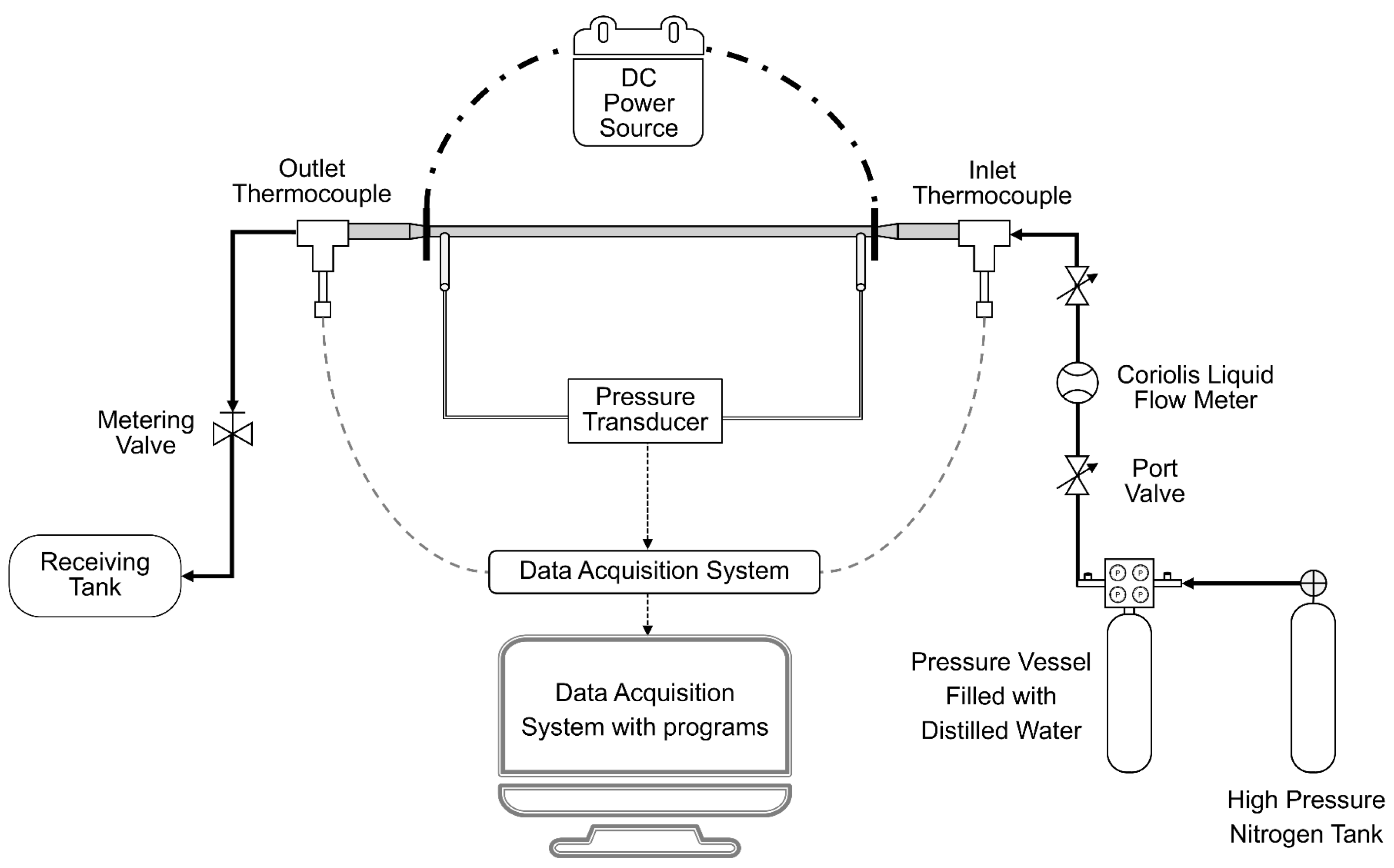
The experimental setup is shown in Figure 1. It consists of a fluid supply system, a test section with heating elements, and measurement instrumentation with a data acquisition (DAQ) system. Distilled water was delivered to the test section by pressurized nitrogen. The volumetric flow rate was measured with a Micro Motion F Series Coriolis flow metre (Emerson, St. Louis, MO, USA). A uniform wall heat flux ranging from 20 to 90 kW/m2 was imposed by passing current through the test section wall via welded electrical wires connected to a direct-current (DC) power supply (KXN-15200D, Zhaoxin, Shenzhen, China). Pressure drop was measured using differential pressure transducers (Validyne DP15, Validyne Engineering, Northridge, CA, USA and OMEGA PX409-10WDWUV, OMEGA Engineering, Norwalk, CT, USA), selected to match the measurement range required for each test section.
Figure 1.
Schematic diagram of the experimental setup.
2.2. Test Section
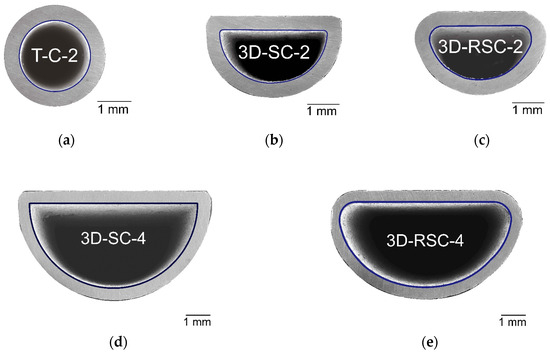
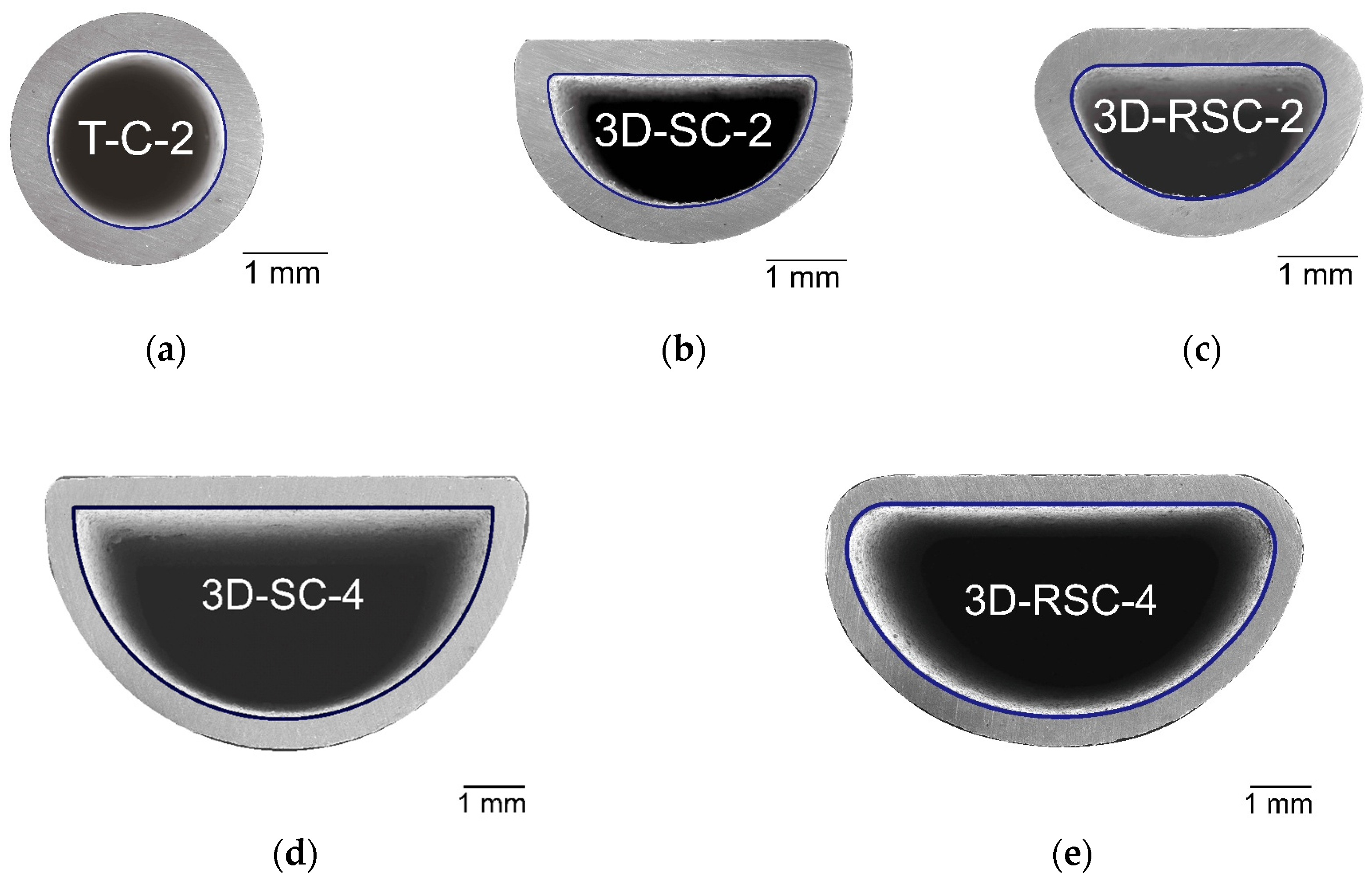
Five test sections were used: one conventional cold-rolled stainless steel circular tube (T-C-2) for the setup validation, two 3D-printed semicircular channels (Dh ≈ 2 mm and Dh ≈ 4 mm), and two 3D-printed rounded-edge semicircular channels (Dh ≈ 2 mm and Dh ≈ 4 mm). For the rounded-edge geometry, the corner radius was set to 0.1 times the inner diameter (rc = 0.1Di). The wall thickness was 0.5 mm in all test sections. The four SLM 3D-printed test sections were all fabricated from stainless steel by a commercial metal AM supplier (Bright Laser Technologies Co., Ltd., Xi’an, China). All SLM test sections were built with the channel axis aligned with the vertical build direction. The AM process parameters were 50 µm layer thickness, 80 µm laser spot, and 15–53 µm powder size. No post-processing was performed after 3D printing as this study aims at investigating the friction factor based on the original surface characteristics of commercial SLM 3D-printed channels. Cross-sectional views of the test sections are shown in Figure 2 using scanning electron microscopy (SEM) (Hitachi S-3400N, Hitachi, Tokyo, Japan). The hydraulic diameters (Dh) of all test sections were determined from SEM images, with cross-sectional area and wetted perimeter calculated using computer software Autodesk AutoCAD 2019 (Autodesk, San Francisco, CA, USA).
Figure 2.
Cross-sectional view of the test sections: (a) T-C-2; (b) 3D-SC-2; (c) 3D-RSC-2; (d) 3D-SC-4; (e) 3D-RSC-4.
Relative roughness in internal flow is conventionally expressed using the equivalent sand-grain roughness in classical correlations. For SLM 3D-printed channels, the relationship between Ra and ε is not unique because the hydraulic effect depends not only on the mean roughness amplitude but also on the spatial distribution, protrusion shape, local blockage caused by partially melted particles, and material accumulation. Referring to Stimpson et al. [17] and Chen et al. [19], Ra/Dh can be the working definition of relative roughness for SLM 3D-printed channels. The Ra of the test sections was measured with an optical profilometer (Bruker Contour GT-X, Bruker, Billerica, MA, USA) and is reported as Ra/Dh to provide a measurable roughness parameter for comparison among the present SLM 3D-printed channels. The measured dimensions and roughness values are listed in Table 1. Although the SLM process yields similar absolute roughness values for the 2 mm and 4 mm channels (refer to Table 1), the smaller-diameter test sections (3D-SC-2 and 3D-RSC-2) have substantially higher relative roughness than their 4 mm counterparts (3D-SC-4 and 3D-RSC-4).
Table 1.
Specifications and measurement data for the testing section.
2.3. Measuring Station
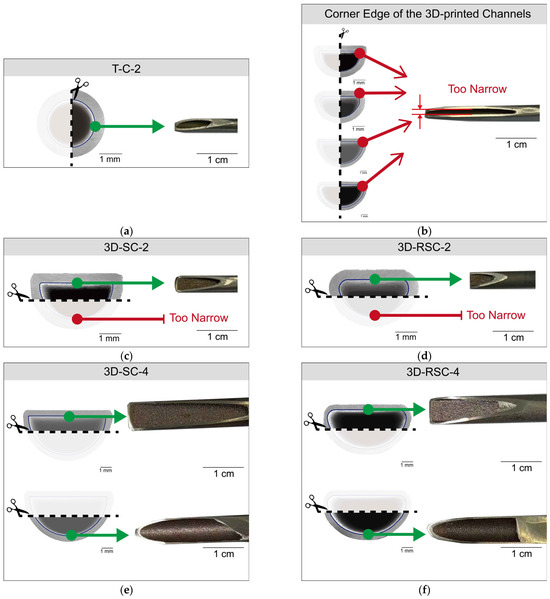
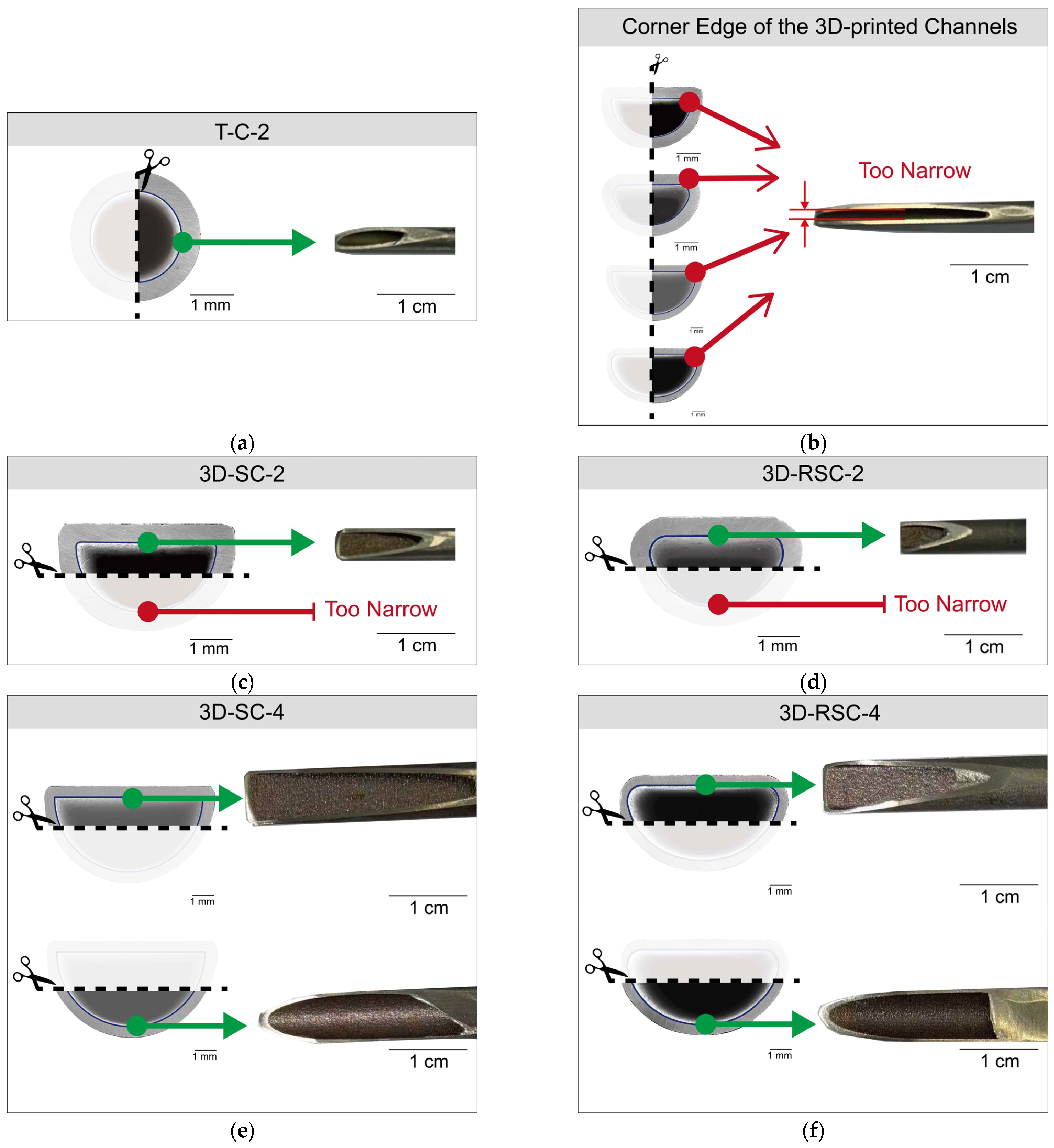
The measuring stations of average surface roughness are shown in Figure 3. Roughness measurements for the sharp edge and rounded edge of the channels could not be performed using the optical profilometer due to measurement limitations for large-curvature surfaces. Consequently, for the 4 mm channel, measurements were conducted on both the top flat and bottom curved surfaces. However, for the 2 mm channels, roughness measurements could not be performed on the curved bottom surface due to the small channel size; accessible sampling regions were only located on the upper flat surface. Consequently, the listed Ra/Dh values may underestimate the effective hydraulic roughness of the 2 mm channels.
Figure 3.
Demonstration of the average surface roughness measuring station: (a) T-C-2; (b) 3D-printed channels; (c) 3D-SC-2; (d) 3D-RSC-2; (e) 3D-SC-4; (f) 3D-RSC-4.
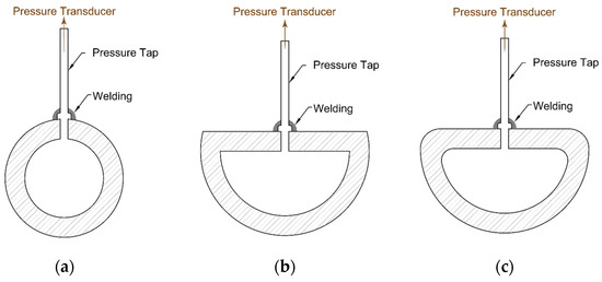
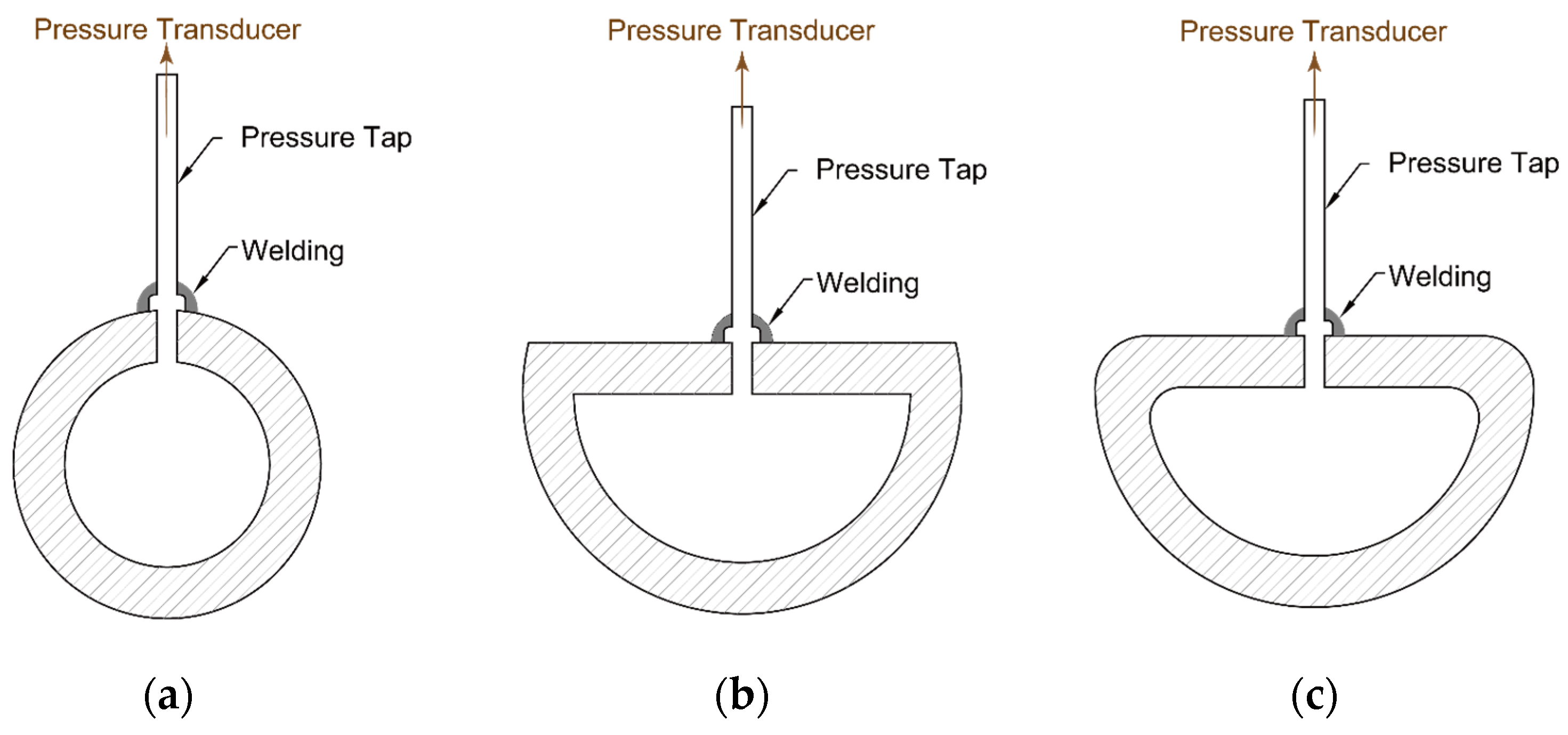
Pressure taps were fabricated as small-diameter bulge tubes and installed in pairs through holes drilled into the top surface of each test section. For semicircular and rounded-edge semicircular channels, the taps were positioned at the uppermost point of the cross-section, as shown in Figure 4.
Figure 4.
Schematic diagram of the pressure taps installation arrangement: (a) circular channel; (b) semicircular channel; (c) rounded-edge semicircular channel.
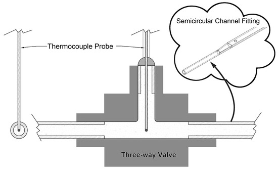
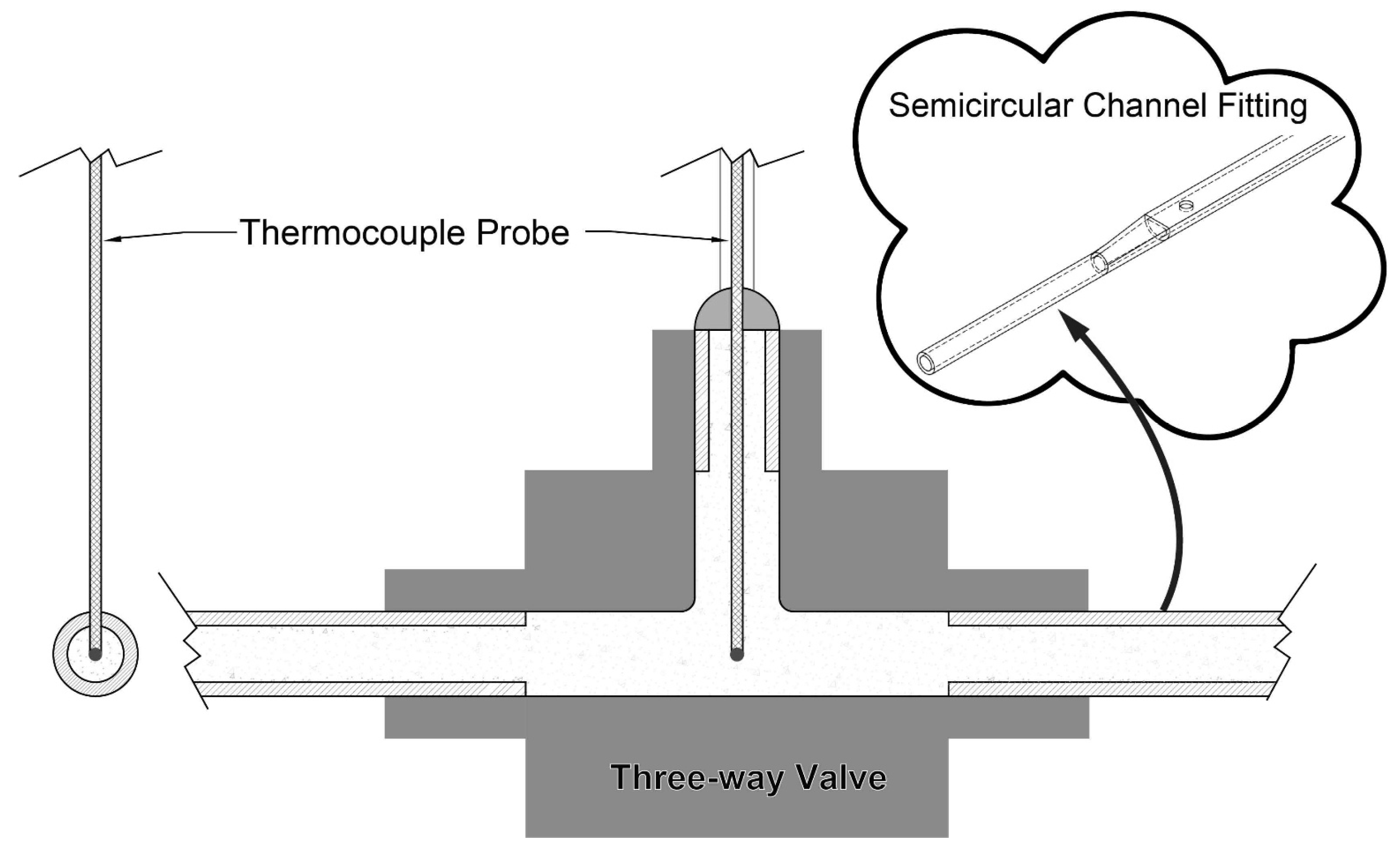
Inlet and outlet bulk temperatures were measured with thermocouple probes (Omega™ TMQSS-020U-6, Omega Engineering, Norwalk, CT, USA) inserted into the central ports of three-way valves. Wall temperatures were monitored at multiple axial positions using surface thermocouples (Omega™ TC-TT-T-40-36, Omega Engineering, Norwalk, CT, USA). The thermocouple arrangements are illustrated in Figure 5. The outer surface of the test sections and the valves were wrapped with thermal insulation to reduce heat loss during heating.
Figure 5.
Thermocouple probe installation arrangement.
2.4. Data Reduction Assumption
Data reduction followed the methodology of Ghajar and Kim [25], assisted by a custom MATLAB® programme (MathWorks, Natick, MA, USA; version R2024a) under the assumption of steady-state conditions. Inputs include channel geometry, DC supply current and voltage, volumetric flow rate, pressure drop, and inlet and outlet temperatures. The hydraulic diameter of the Reynolds number and friction factor calculations are based on the measured values from the SEM images in Figure 2 and the list in Table 1. Fluid thermophysical properties were evaluated at the mean bulk temperature of the inlet and outlet. The thermophysical properties of water were calculated using the correlations given in Appendix A.
2.5. Uncertainty Analysis
Measurement uncertainties were calculated using the method of Kline and McClintock [26], and the heat balance error was evaluated following Ghajar and Kim [25]. The resulting uncertainties are summarized in Table 2. The friction factor uncertainty was based on the uncertainties in pressure drop, flow rate, channel geometry, and temperature-dependent fluid properties. The heat balance error was calculated by comparing the energy change in the water between the inlet and outlet with the electrical power input. Possible sources of heat balance error include heat loss through fittings and insulation, uncertainty in electrical power input, and thermocouple placement.
Table 2.
Results of the uncertainty analysis.
3. Results and Discussion
In this section, the experimental measurements are presented and discussed and the friction factors of the additively manufactured test sections are analyzed. The reliability of the experimental setup is first verified. After the verification, the effects of different channel surface morphologies, hydraulic diameters, and filleting on the hydraulic performance are analyzed. The experimental friction factor results are compared with the existing correlations listed in Table 3.
Table 3.
Existing friction factor correlations used for comparison.
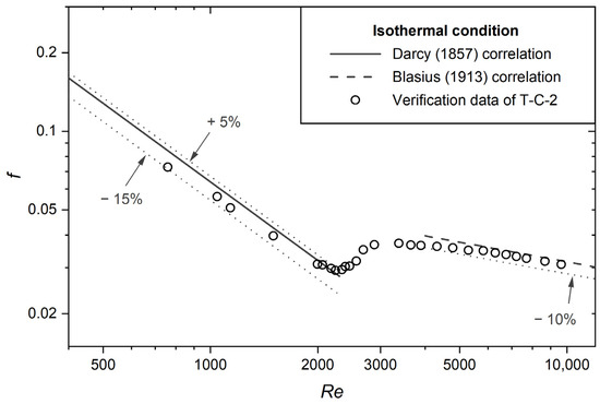
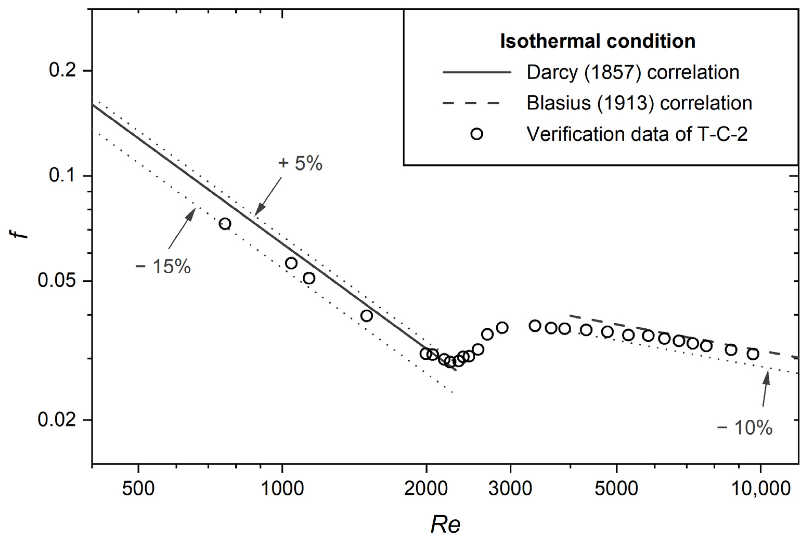
The experimental setup was validated using the cold-rolled circular tube T-C-2 (Di = 2.06 mm). Figure 6 shows the measured friction factor under isothermal conditions over Re ranging from 800 to 10,000. In the laminar regime (800 ≤ Re ≤ 2300), the data agree with the Darcy correlation [27] to within an average deviation of 3.44% and a maximum of 13.64%. In the turbulent regime (4000 ≤ Re ≤ 10,000), agreement with the Blasius correlation [29] is within 4.37% on average and 7.19% at most, confirming reliable pressure drop measurements.
Figure 6.
Verification of pressure drop results with T-C-2 [27,29].
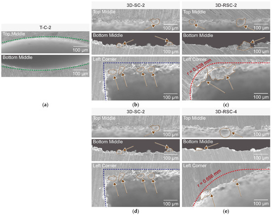
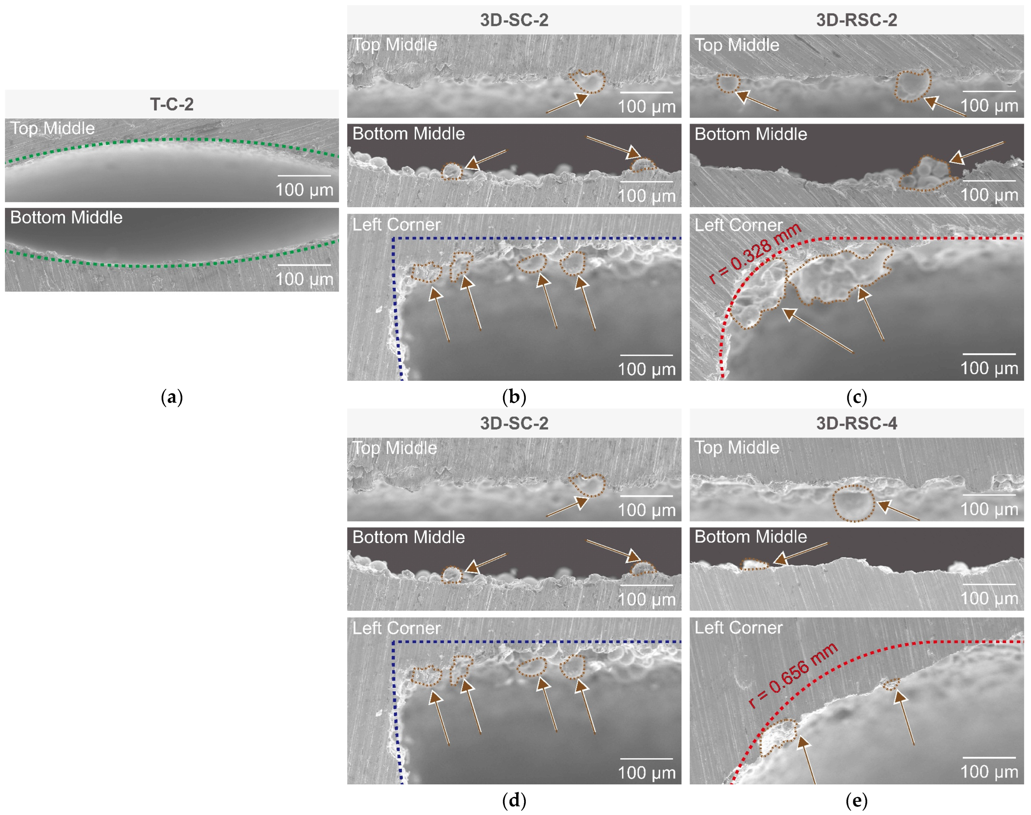
SEM images of the five test sections are shown in Figure 7, with dashed lines indicating the designed channel geometry. In Figure 7, although the vertical build orientation has the advantage of reducing long-span ceiling sagging compared with horizontal build orientation, local material accumulation still easily occurs near the corner. This material accumulation is formed by incomplete melting that produces spatter and dross around the heat-affected zone under the non-ideal laser spot [11]. The T-C-2 inner wall (Figure 7a) is smooth with no visible irregularities. The 3D-printed channels (Figure 7b–e) all deviate from the intended geometry, with material accumulation along the inner walls (annotated with arrows), especially concentrated near the corners. In the semicircular channels (3D-SC-2 and 3D-SC-4), a short, sloping surface is formed at the corner of the channel, giving it a chamfered appearance. Essentially, a local edge replaces the original single sharp vertex. The rounded-edge channels exhibit a distinct feature: material accumulation is more concentrated and pronounced at the rounded edge of the design. Especially in 3D-RSC-2 (Figure 7c), obvious spherical defects are visible at the corners.
Figure 7.
Surface characteristics of the test sections: (a) T-C-2; (b) 3D-SC-2; (c) 3D-RSC-2; (d) 3D-SC-4; (e) 3D-RSC-4.
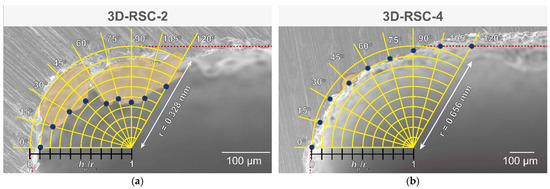
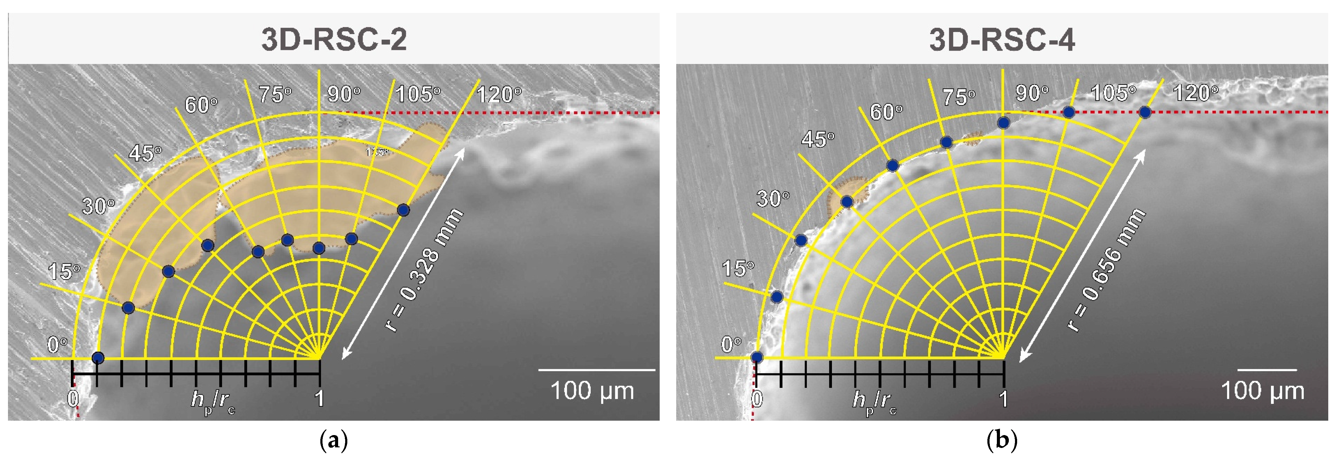
The local protrusion height near the rounded edge was quantified using the ratio (hp/rc) of the protrusion height (hp) to the corner radius (rc) from the SEM images. The hp/rc value was used only to characterize localized material accumulation and was not merged into the Ra/Dh data reduction. Figure 8 and Table 4 quantify the hp/rc as the angle ranges from 0° to 120°. The average hp/rc of 3D-RSC-2 is 0.37, while the average value of 3D-RSC-4 is 0.05, a difference of 7.4 times. The size dependence reflects the greater difficulty in manufacturing small-radius rounded edges precisely. That is, as rc decreases, the local curvature increases, and defects generated by the SLM process become more pronounced. Therefore, filleting the semicircular geometry for the 2 mm hydraulic diameter channel does not actually smooth the edge. It also significantly deteriorates the local surface condition, resulting in a rougher surface than that of a 3D-printed semicircular channel.
Figure 8.
Material accumulation concentrated at the corners of the test sections: (a) 3D-RSC-2; (b) 3D-RSC-4.
Table 4.
Comparison of concentrated surface accumulation.
Referring to the discussion of Figure 7 and Figure 8, the fillet geometry and the SLM-induced local morphology are physically coupled in the as-built channels; therefore, the present experiments cannot completely isolate the ideal smooth filleting effect from manufacturing-induced roughness. It is simply the limitation of this particular manufacturing process. Therefore, the following results and discussion of the SLM 3D-printed test sections cannot represent the smooth channel with rounded edges. The performance of the SLM 3D-printed test sections is related to the actual non-ideal surface shown in Figure 7 and Figure 8.
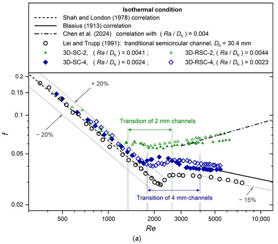
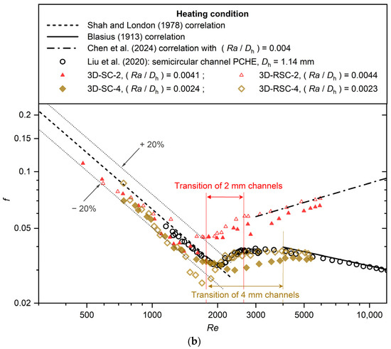
Friction factors for all four 3D-printed test sections are compared with reference data in Figure 9. Comparing Figure 9a and Figure 9b, the friction factors of all 3D-printed channels under heating conditions were lower than those under isothermal conditions, with a 13.41% and 14.30% average reduction, respectively. Heating introduces non-isothermal property variations along the channel as viscosity decreases, which results in a decrease in friction factor [19].
Figure 9.
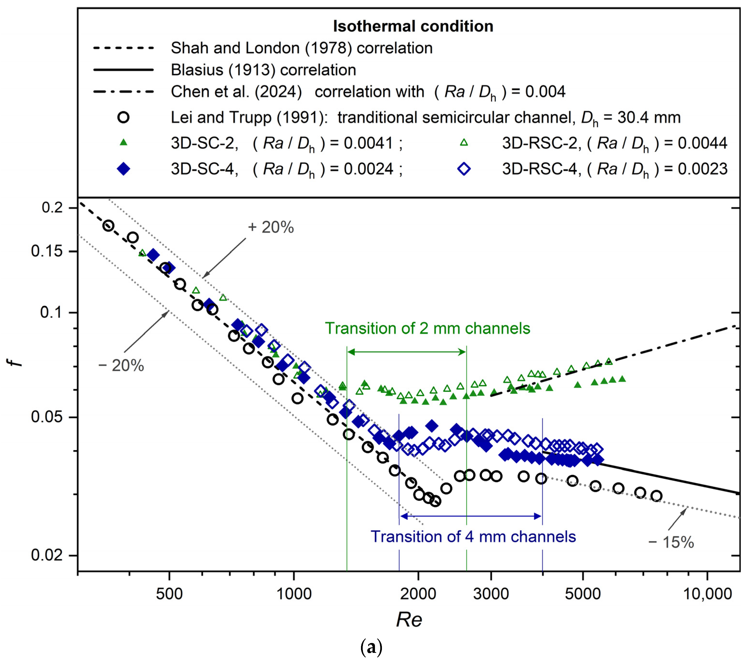
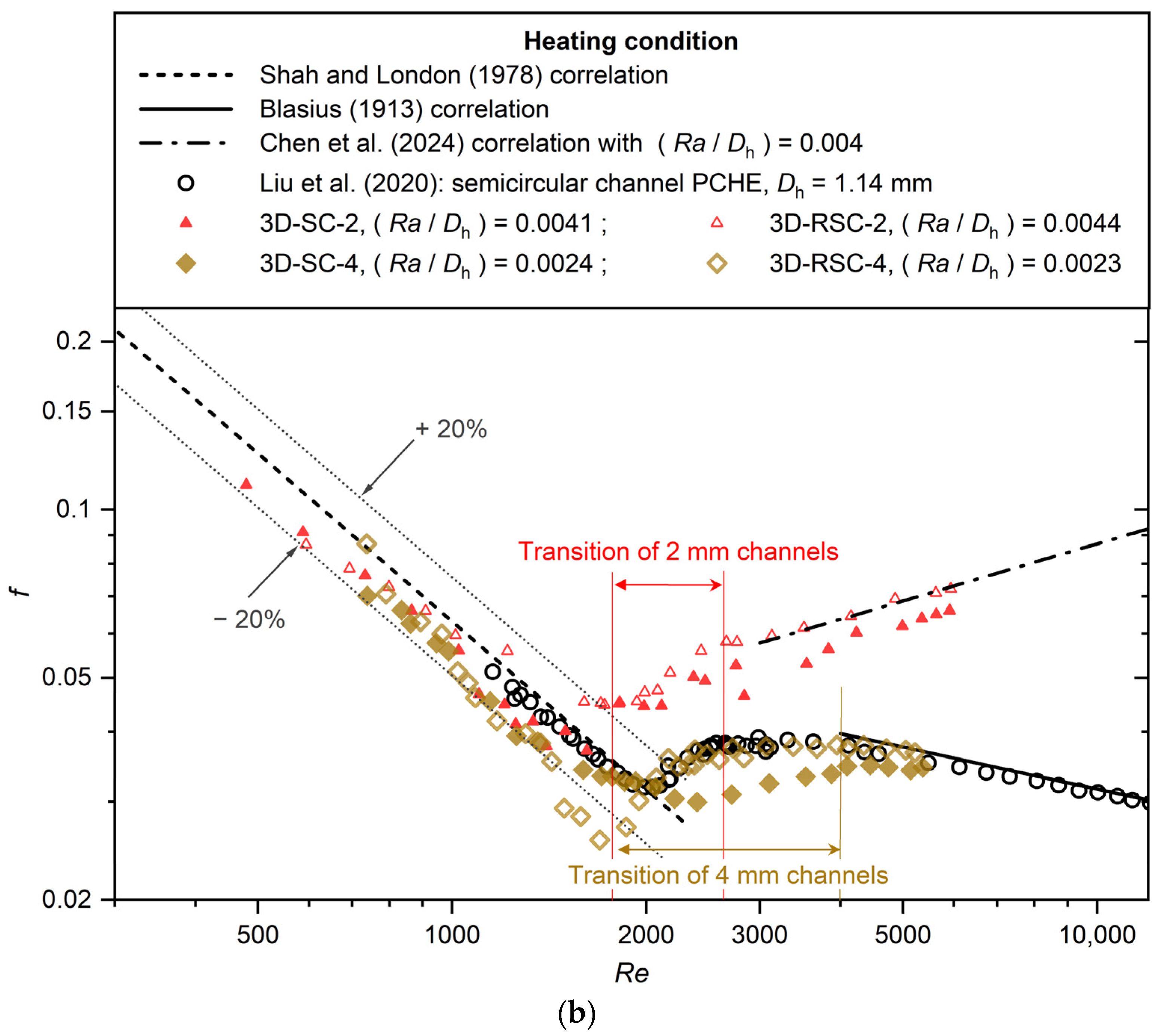
Comparison of friction factors for 3D-printed semicircular and rounded-edge semicircular channels under (a) isothermal and (b) heating conditions [21,28,29,30,31].
The transition Reynolds number range of the 3D-printed channels was first evaluated. The onset of transition from laminar to turbulent flow was estimated based on changes in the friction factor trend shown in Figure 9.
Under isothermal conditions, as indicated in Figure 9a, the transition begins at Reynolds numbers of approximately 1400 and 1800 for the 2 mm and 4 mm 3D-printed channels, respectively. In comparison, according to the experimental data by Lei and Trupp [31] for a traditional copper semicircular channel (Dh = 30.4 mm) in isothermal conditions, the transition Reynolds number range starts from about 2300. On the other hand, Chen et al. [30] reported that the transition Reynolds number of a 3D-printed rough circular channel (Dh = 2 mm; Ra/Dh = 0.007387) in isothermal conditions starts from 1400, which is about the same as in this study.
Under heating conditions, as indicated in Figure 9b, the transition begins at Reynolds numbers of approximately 1800 for both the 2 mm and 4 mm 3D-printed channels. In comparison, according to the experimental results by Liu et al. [21] for an etching PCHE semicircular channel (Dh = 1.14 mm), the transition starts from a Reynolds number of about 2100. On the other hand, Chen et al. [19] also measured the transition of a 3D-printed circular rough channel in heating conditions and obtained a transition range starting from a Reynolds number of about 2000.
Overall, the 3D-printed channels exhibit an earlier transition than that reported for conventional smooth channels. This is due to the instability of the flow due to surface roughness, which promotes an earlier transition. Therefore, the transition region of the 3D-printed channel differs from the classical transition region where the Reynolds number ranges from about 2300 to 4000. As observed in Figure 9, the Reynolds number range for the transition region of 3D-SC-2 and 3D-RSC-2 is from 1400 to 2600, whereas that for 3D-SC-4 and 3D-RSC-4 is from 1800 to 4000.
For a comparison between the SLM 3D-printed channel and the PCHE etched channel, Figure 9b shows that the 4 mm rounded-edge channel has a similar friction factor tendency with the PCHE etched semicircular channel data by Liu et al. [21] in the transition and turbulent regimes under heating conditions. On the other hand, the 2 mm channel data deviate substantially from Liu et al. [21]’s data. It is proposed that if a hydraulically smooth surface roughness of the SLM 3D-printed channel can be achieved (e.g., Ra/Dh < 0.0028 in Stimpson et al. [17]), the friction factor performance can be close to that of the etching channels in the PCHE core.
Table 5 and Table 6 present a comparison of friction factors for the 2 mm and 4 mm 3D-printed channels investigated in this study. In the turbulent regime, the friction factor of the 3D-RSC-2 channel is 10.30% (isothermal) and 13.9% (heating) higher than that of the 3D-SC-2 channel. Similarly, for the 4 mm channels, the friction factor of the 3D-RSC-4 channel is 8.63% (isothermal) and 8.03% (heating) higher than that of the 3D-SC-4 channel. Overall, the friction factor of the RSC channels is approximately 9% higher than that of the SC channels on average.
Table 5.
Comparison of friction factor deviation between 3D-SC-2 and 3D-RSC-2 channels.
Table 6.
Comparison of friction factor deviation between 3D-SC-4 and 3D-RSC-4 channels.
It is important to distinguish the intended geometric effect of corner filleting from the actual AM surface morphology. The present SEM observations show that the as-built rounded-edge channels did not preserve this ideal geometry. Instead, the designed fillet region became a preferential location for local material accumulation and partially melted powder adhesion. Therefore, the higher friction factors measured in the rounded-edge semicircular channels should not be interpreted as evidence that an ideal geometric fillet intrinsically increases hydraulic losses. Rather, the results indicate that, under the present SLM fabrication conditions, the rounded-edge design produced an as-built surface morphology with localized protrusions near the filleted corners. These manufacturing-induced features increased the roughness and dominated the friction factor response. The present experiments therefore quantify the hydraulic effect of the as-built rounded-edge morphology, while the isolated effect of an ideal smooth fillet would require post-processing the rough channel to make it smooth in a future study.
In the laminar regime in Figure 9a,b, for all 3D-printed channels used in this study, an average friction factor deviation of 10.87% and 17.47% for the isothermal and heating boundary conditions is observed compared with the Shah and London [28] correlation. Under isothermal conditions, data essentially follows the traditional trend with reasonable accuracy. Under heating conditions, the larger deviations from the correlation of Shah and London [28] should be attributed to non-isothermal variations in fluid properties and flow development.
In the turbulent regime in Figure 9a,b, the 2 mm channels have a completely different trend, which is moving upward, whereas the downward-moving trend of the 4 mm channels is similar to that of the Blasius [29] equation. The difference in friction factor magnitude between the 2 mm and 4 mm channels is also substantial. The experimental data of the 4 mm 3D-printed channels were compared with the Blasius [29] correlation (downward trend for the smooth circular channel) and Chen et al.’s [30] correlation (upward trend for the 3D-printed circular channel) in the turbulent regime. The deviation between the experimental data and the correlations (in the corresponding applicable range of parameters) is listed in Table 7.
Table 7.
Comparison between experimental friction factors and those predicted by the reference correlations.
In Table 7, the Blasius [29] correlation is applicable to the 4 mm channels with the error always below 11% in all cases. Since Stimpson et al. [17] proposed that SLM 3D-printed channels can be treated as hydraulically smooth when Ra/Dh < 0.0028, the use of the Blasius correlation for the 4 mm channels (Ra/Dh < 0.0024) is reasonable. However, the Blasius [29] correlation is not applicable to the 2 mm channels since the error always exceeds 40% in all cases. This is due to the fact that the high relative roughness of the 2 mm channels (about 0.0041 to 0.0044) cannot fulfil the hydraulically smooth requirement of the Blasius [29] correlation. Conversely, Chen et al.’s [30] correlation is not applicable to the 4 mm channels since the error always exceeds 50% in all conditions. This is because the relative roughness of the 4 mm channels (about 0.0023 to 0.0024) is much lower than the range considered by Chen et al. [30] (about 0.01212 to 0.02229).
For the 2 mm channels, even though the measured relative roughness (about 0.0041 to 0.0044) is smaller than the range (0.01212 to 0.02229) of Chen et al. [30], the errors are always below 11% in all cases. This agreement may be associated with (1) the similar hydraulic diameter and (2) the possibility that the effective roughness of the present 2 mm channels is underestimated. Because of the small channel size and measurement limitations, roughness sampling was mainly limited to the upper flat surface and did not fully capture the curved bottom surface or the severe material accumulation defects near the corners (refer to Figure 3). By contrast, material accumulation defects in the 4 mm channels were not significant, and the surface roughness, averaged from measurements taken on both the upper and lower surfaces, was therefore more representative. Therefore, the actual effective relative roughness of the 2 mm channels is probably higher than the values listed in Table 1 and may be closer to the range considered by Chen et al. [30]. This uncertainty motivated the development of a new correlation covering a wider Reynolds number range and a broader spectrum of relative roughness.
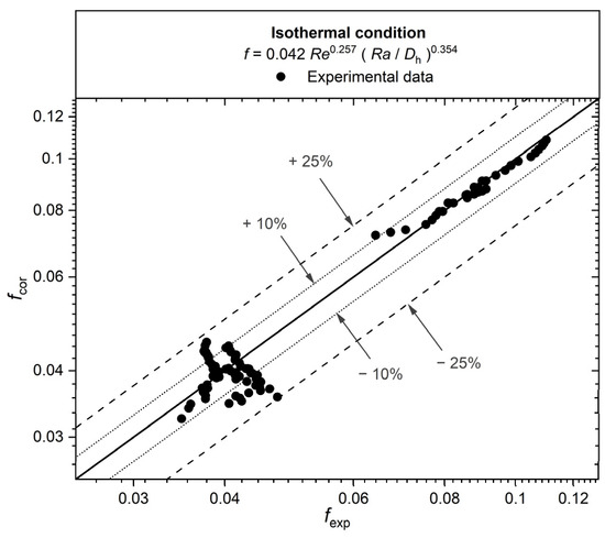
The experimental data for the 4 mm channels in this study and the 2 mm channel of Chen et al. [30] were used to develop new correlations for isothermal and heating conditions. Data from Chen et al. [30] were included to extend the fitting database to higher relative roughness values for SLM 3D-printed mini-channels, whereas the present 2 mm semicircular channel data were excluded because their effective relative roughness is uncertain. The correlation for isothermal conditions is shown as Equation (1):
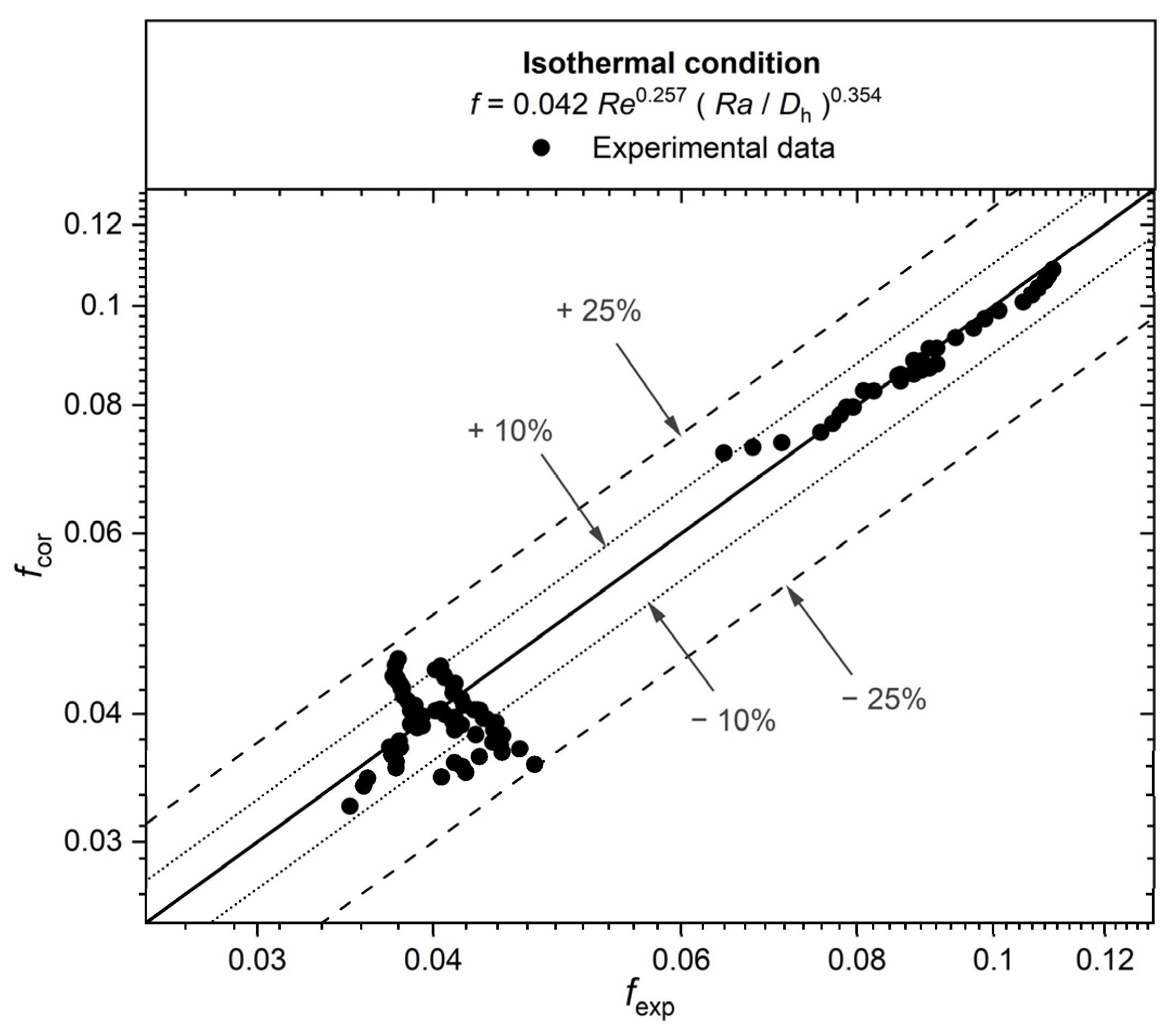
where Re is based on the mean value of inlet and outlet bulk temperatures, and Ra/Dh is the inside-wall relative roughness of the channels. Equation (1) was derived using least squares fitting based on 76 isothermal experimental data points from 3D-SC-4, 3D-RSC-4, and Chen et al. [30]. As shown in Figure 10, Equation (1) has an absolute average deviation of 8.0% and a maximum deviation of 24.5%.
Figure 10.
Comparison of friction factor experimental results with proposed correlation predictions under isothermal conditions.
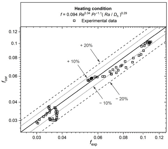
The correlation for heating conditions is shown as Equation (2):
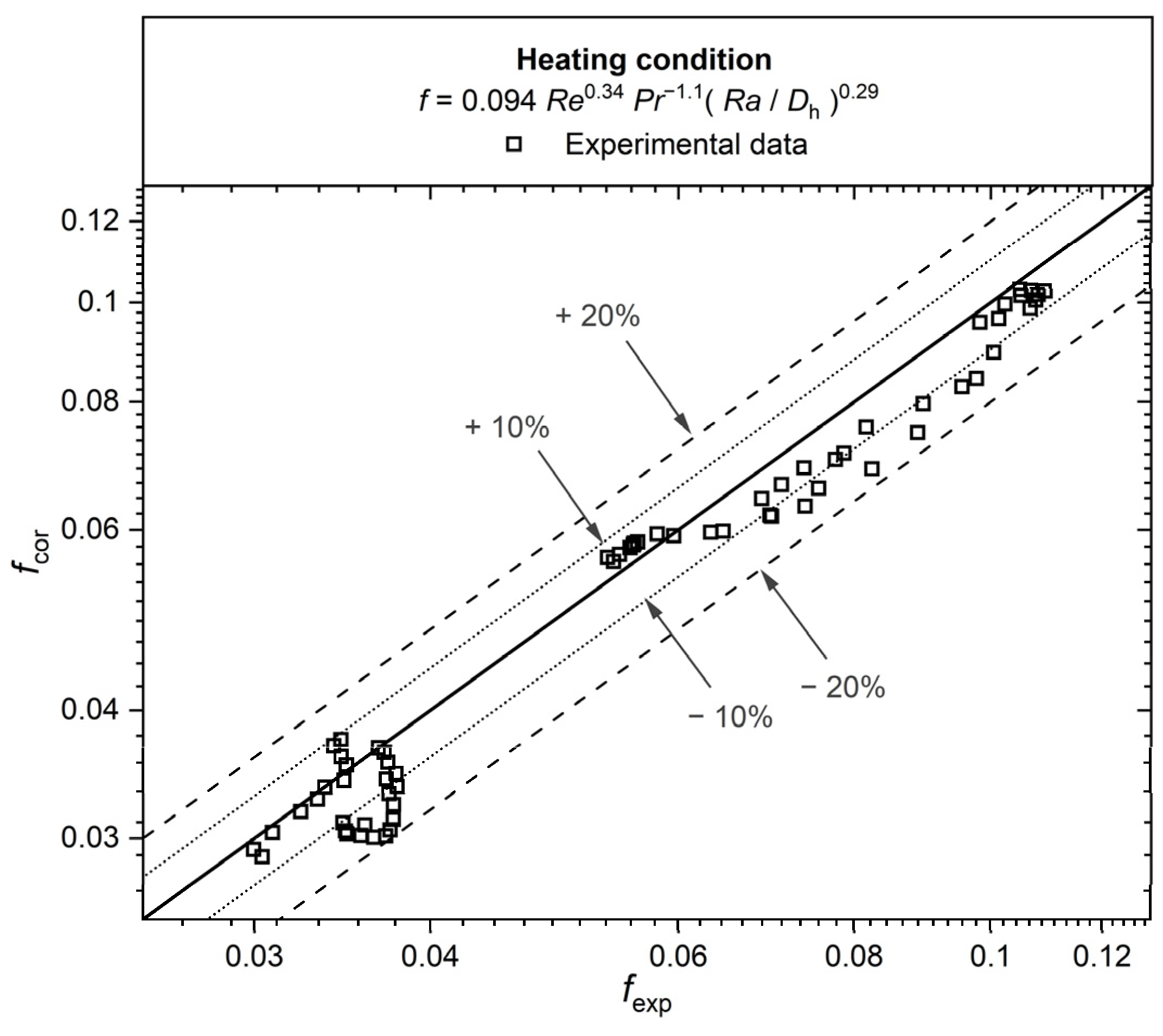
where Re and Pr are based on the mean value of inlet and outlet bulk temperatures, and Ra/Dh is the inside-wall relative roughness of the channels. Equation (2) was derived using least squares fitting based on 65 heating experimental data from 3D-SC-4, 3D-RSC-4, and Chen et al. [30]. As shown in Figure 11, Equation (2) has an absolute average deviation of 7.7% and a maximum deviation of 18.9%. The use of these correlations should be limited to the suggested parameter ranges and manufacturing conditions represented by the fitting database.
Figure 11.
Comparison of friction factor experimental results with proposed correlation predictions under heating conditions.
4. Conclusions
In this study, SLM was employed to fabricate semicircular and rounded-edge semicircular channels. The friction factors of all channels were experimentally investigated using water as the working fluid under laminar, transitional, and turbulent flow conditions. The results were compared with data and correlations for cold-rolled circular tubes, etched PCHE channels, and 3D-printed circular channels. The following conclusions were drawn:
- In the laminar regime, the friction factor of the rounded-edge semicircular channels is comparable to that of the plain semicircular channels at both hydraulic diameters, and both are reasonably predicted by the Shah and London correlation [28]. Surface roughness has a negligible effect on laminar friction factors in these channels.
- In the transition regime, all four 3D-printed test sections exhibit an earlier laminar-to-turbulent transition than conventional smooth circular and semicircular channels.
- In the turbulent regime, higher relative roughness leads to higher friction factors. For rounded-edge channels, material accumulation concentrated near the rounded edges further increases friction losses. The friction factor of the 2 mm rounded-edge channel (3D-RSC-2) is consistent with the established correlation for rough 3D-printed circular channels [30].
- The SEM images of the SLM 3D-printed channels showed that material accumulation was concentrated at the corners and was especially pronounced near the rounded edges. As a result, the rounded-edge semicircular channels exhibited friction factors approximately 9% higher than those of the corresponding semicircular channels. This result should be interpreted as the combined effect of the intended filleting design and the as-built SLM material-accumulation morphology, rather than the isolated effect of an ideal smooth rounded edge.
- Two empirical correlations were proposed for isothermal and heating conditions in the transition-to-turbulent Reynolds number range within the fitted database. These correlations predict the friction factor of SLM 3D-printed semicircular, rounded-edge semicircular, and circular mini-channels within the specified Reynolds number, Prandtl number, and relative surface roughness ranges.
Author Contributions
Writing—original draft: L.L.; methodology, validation, investigation, visualization, and data curation: L.L., Y.Y. and J.C.; writing—review and editing: Y.Y. and J.C.; supervision and writing—review and editing: L.M.T. and A.J.G.; project administration and funding acquisition: L.M.T. All authors have read and agreed to the published version of the manuscript.
Funding
This work was supported by the Macao Science and Technology Development Fund (FDCT) and the Ministry of Science and Technology of China (MOST) (0074/2023/AMJ), as well as the Institute for the Development and Quality, Macau.
Data Availability Statement
The data presented in this study are contained within the article.
Conflicts of Interest
The authors declare no conflicts of interest.
Abbreviations
The following abbreviations are used in this manuscript:
| AM | Additive manufacturing |
| cp | Specific heat capacity, J/kg·K |
| Dh | Hydraulic diameter of the test section, m |
| Di | Inside diameter of the test section, m or mm |
| DAQ | Data acquisition |
| DC | Direct current |
| exp | Experiment |
| f | Darcy friction factor, dimensionless |
| h | Heat transfer coefficient, W/(m2·K) |
| hp | Protrusion height, m |
| j | Colburn j-factor, dimensionless |
| k | Thermal conductivity, W/(m·K) |
| L | Length, m |
| Nu | Nusselt number (=h·Dh/k), dimensionless |
| PCHE | Printed circuit heat exchanger |
| Pr | Prandtl number (=cp·μb/k), dimensionless |
| P | Wetted perimeter of the cross-section, m |
| p | Pressure, Pa |
| q | Heat flux, W/m2 |
| Ra | Average surface roughness, μm |
| Re | Reynolds number (=ρ·u·Dh/·μ), dimensionless |
| RSC | Rounded-edge semicircular |
| rc | Corner radius of the rounded edge, m or mm |
| SC | Semicircular |
| SEM | Scanning electron microscopy |
| SLM | Selective laser melting |
| T | Temperature, °C or K |
| u | Velocity, m/s |
| x | Local axial distance along the test section from the inlet, m or mm |
| β | Coefficient of thermal expansion, 1/K |
| γ | Electrical resistivity, μΩ·cm |
| ε | Equivalent sand-grain roughness, μm |
| μ | Viscosity, Pa·s |
| ρ | Density, kg/m3 |
Appendix A. Water Thermophysical Properties
In the calculations, the following thermophysical-property equations were used, which were adopted from the data-reduction methods of Ghajar and Kim [25].
The density of water was taken from Chen [32] and is given by
where ρwater is the density of water and Tb (°C) is the water temperature.
The viscosity of water was taken from Abdelmessih [33] and is given by
where μwater (Pa·s) is the viscosity of water and Tb (°C) is water temperature.
The specific heat capacity of water was taken from Abdelmessih [33] and given by
where (kJ/kg·K) is the specific heat capacity of water and Tb (°C) is the water temperature.
The thermal conductivity of water was taken from Abdelmessih [33] and is given by
where kwater (W/(m·K)) is the thermal conductivity of water and Tb (°C) is the water temperature.
References
- Ma, Y.; Xie, G.; Hooman, K. Review of printed circuit heat exchangers and its applications in solar thermal energy. Renew. Sustain. Energy Rev. 2022, 155, 111933. [Google Scholar] [CrossRef] [Scilit]
- Tsuzuki, N.; Kato, Y.; Ishiduka, T. High performance printed circuit heat exchanger. Appl. Therm. Eng. 2007, 27, 1702–1707. [Google Scholar] [CrossRef] [Scilit]
- Ma, Y.; Liu, D.; Wang, J.; Zeng, M.; Wang, Q.; Ma, T. Thermal-hydraulic performance and optimization of printed circuit heat exchangers for supercritical fluids: A review. Renew. Sustain. Energy Rev. 2025, 208, 115051. [Google Scholar] [CrossRef] [Scilit]
- Rao, P.N.; Kunzru, D. Fabrication of microchannels on stainless steel by wet chemical etching. J. Micromech. Microeng. 2007, 17, N99–N106. [Google Scholar] [CrossRef] [Scilit]
- Yoon, S.H.; Shin, J.H.; Kim, D.H.; Choi, J.S. Design of printed circuit heat exchanger (PCHE) for LNG re-gasification system. In Proceedings of the ASME 2017 International Mechanical Engineering Congress and Exposition, Tampa, FL, USA, 3–9 November 2017. [Google Scholar] [CrossRef] [Scilit]
- Tang, J.; Liu, M.; Huang, Y.; Liu, G.; Zang, J.; Liu, S. Effect of manufacturing deviations on the thermohydraulic performance of printed circuit heat exchangers with zigzag channels. Appl. Therm. Eng. 2023, 219, 119496. [Google Scholar] [CrossRef] [Scilit]
- Shen, J.; Ma, Z.; Chen, H. Shakedown and ratcheting analysis of Printed Circuit Heat Exchangers under multiple cyclic mechanical and thermal loads. Int. J. Press. Vessel. Pip. 2022, 199, 104723. [Google Scholar] [CrossRef] [Scilit]
- Jamei, M.; Alashti, M.H.; Abbasi, M.; EbrahimNejad, A.; Taheri, M.H. Impact of round edge on the duct fluid flow: Analytical investigation. SN Appl. Sci. 2021, 3, 431. [Google Scholar] [CrossRef] [Scilit]
- Sparrow, E.M.; Hossfeld, L.M. Effect of rounding of protruding edges on heat transfer and pressure drop in a duct. Int. J. Heat Mass Transf. 1984, 27, 1715–1723. [Google Scholar] [CrossRef] [Scilit]
- Yang, K. Thermal Performance and Pressure Drop of the Compact Heat Exchangers Based on DMLS. Master’s Thesis, University of Pittsburgh, Pittsburgh, PA, USA, 2020. [Google Scholar]
- Xu, D.; Liu, D.; Han, Z.; Ma, Q.; Zheng, D.; Ma, T. Experimental study on flow resistance of mini-channels fabricated via in-situ low-resistance selective laser melting. Int. Commun. Heat Mass Transf. 2026, 175, 111028. [Google Scholar] [CrossRef] [Scilit]
- da Silva, R.P.P.; Mortean, M.V.V.; de Paiva, K.V.; Beckedorff, L.E.; Oliveira, J.L.G.; Brandão, F.G.; Monteiro, A.S.; Carvalho, C.S.; Oliveira, H.R.; Borges, D.G.; et al. Thermal and hydrodynamic analysis of a compact heat exchanger produced by additive manufacturing. Appl. Therm. Eng. 2021, 193, 116973. [Google Scholar] [CrossRef] [Scilit]
- Li, B.; Liu, Q.; Chen, Y.; Hu, W.; Huang, Y.D. The effect of transition fillets on the surface quality of arched overhanging structures created by SLM. Prog. Addit. Manuf. 2025, 11, 1361–1375. [Google Scholar] [CrossRef] [Scilit]
- Van, C.N.; Le Hoang, A.; Long, C.D.; Hoang, D.N. Surface roughness in metal material extrusion 3D printing: The influence of printing orientation and the development of a predictive model. Eng. Technol. Appl. Sci. Res. 2023, 13, 11672–11676. [Google Scholar] [CrossRef] [Scilit]
- Lokanathan, N.; Mears, Z.; Vlasea, M.L.; Hickey, J.P. Effect of metal additive manufacturing surface roughness on laminar flows. Rapid Prototyp. J. 2026, 32, 1–13. [Google Scholar] [CrossRef] [Scilit]
- Mandloi, K.; Allen, A.; Cherukuri, H.; Miller, J.; Duttrer, B.; Raquet, J. CFD and experimental investigation of AM surfaces with different build orientations. Surf. Topogr. Metrol. Prop. 2023, 11, 034001. [Google Scholar] [CrossRef] [Scilit]
- Stimpson, C.K.; Snyder, J.C.; Thole, K.A.; Mongillo, D. Scaling roughness effects on pressure loss and heat transfer of additively manufactured channels. J. Turbomach. 2017, 139, 021003. [Google Scholar] [CrossRef] [Scilit]
- Su, X.; Zhang, Y.; Rao, Y.; Yeranee, K.; Wang, X. Experimental and numerical study on flow and heat transfer characteristics of additively manufactured triply periodic minimal surface (TPMS) heat exchangers for micro gas turbine. Aerospace 2025, 12, 416. [Google Scholar] [CrossRef] [Scilit]
- Chen, J.H.; Yang, Y.F.; Lam, L.; Zeng, M.; Ma, T.; Tam, L.M.; Ghajar, A.J. Experimental investigation of heat transfer and pressure drop characteristics for vertical downflow using traditional and 3D-printed mini tubes. J. Enhanc. Heat Transf. 2023, 30, 69–82. [Google Scholar] [CrossRef] [Scilit]
- Cao, L.; Zhou, S.; Wang, H.; Liu, C.; Wei, R.; Wang, W.E.; Hu, X.; Zhang, N. The Dominant Role of Relative Roughness in Microscale Flow Transition: Redefining the Critical Reynolds Number for Microflow Measurement. Flow Meas. Instrum. 2025, 108, 103151. [Google Scholar] [CrossRef] [Scilit]
- Liu, S.H.; Huang, Y.P.; Wang, J.F.; Liu, R.L. Experimental study on transitional flow in straight channels of printed circuit heat exchanger. Appl. Therm. Eng. 2020, 181, 115950. [Google Scholar] [CrossRef] [Scilit]
- Chu, W.X.; Li, X.H.; Ma, T.; Chen, Y.T.; Wang, Q.W. Experimental investigation on SCO2-water heat transfer characteristics in a printed circuit heat exchanger with straight channels. Int. J. Heat Mass Transf. 2017, 113, 184–194. [Google Scholar] [CrossRef] [Scilit]
- Li, S.; Huai, W. United Formula for the Friction Factor in the Turbulent Region of Pipe Flow. PLoS ONE 2016, 11, e0154408. [Google Scholar] [CrossRef] [Scilit]
- Everts, E.; Mahomed, F. The effect of high values of relative surface roughness on heat transfer and pressure drop characteristics in the laminar, transitional, quasi-turbulent and turbulent flow regimes. Heat Mass Transf. 2024, 60, 1173–1193. [Google Scholar] [CrossRef] [Scilit]
- Ghajar, A.J.; Kim, J. Calculation of local inside-wall convective heat transfer parameters from measurements of the local outside-wall temperatures along an electrically heated circular tube. In Heat-Transfer Calculations; McGraw-Hill: New York, NY, USA, 2006; pp. 23.23–23.27. [Google Scholar]
- Kline, S.J.; McClintock, F.A. Describing uncertainties in single-sample experiments. Mech. Eng. 1963, 75, 3–8. [Google Scholar]
- Darcy, H. Experimental Research Relating to the Movement of Water in Pipes; Mallet-Bachelier: Paris, France, 1857. [Google Scholar]
- Shah, R.K.; London, A.L. Laminar Flow Forced Convection in Ducts. In Advances in Heat Transfer; Suppl. 1; Academic Press: New York, NY, USA, 1978. [Google Scholar]
- Blasius, H. Das Ähnlichkeitsgesetz bei Reibungsvorgängen in Flüssigkeiten. In Mitteilungen über Forschungsarbeiten auf dem Gebiete des Ingenieurwesens; Springer: Berlin, Germany, 1913; pp. 1–41. [Google Scholar]
- Chen, J.H.; Wu, K.W.; Tam, L.M.; Ghajar, A.J. Experimental study on heat transfer enhancement of 3D-printed mini tubes under three different flow directions. Heat Transf. Eng. 2024, 45, 1502–1514. [Google Scholar] [CrossRef] [Scilit]
- Lei, Q.M.; Trupp, A.C. Experimental study of laminar mixed convection in the entrance region of a horizontal semicircular duct. Int. J. Heat Mass Transf. 1991, 34, 2361–2372. [Google Scholar] [CrossRef] [Scilit]
- Chen, J.H. Heat Transfer in High Transfer Downstream from U-Bends. Ph.D. Thesis, Oklahoma State University, Stillwater, OK, USA, 1986. [Google Scholar]
- Abdelmessih, A.N. Laminar Flow Heat Transfer Downstream from U-Bends. Ph.D. Thesis, Oklahoma State University, Stillwater, OK, USA, 1987. [Google Scholar]

Disclaimer/Publisher’s Note: The statements, opinions and data contained in all publications are solely those of the individual author(s) and contributor(s) and not of MDPI and/or the editor(s). MDPI and/or the editor(s) disclaim responsibility for any injury to people or property resulting from any ideas, methods, instructions or products referred to in the content. |
© 2026 by the authors. Licensee MDPI, Basel, Switzerland. This article is an open access article distributed under the terms and conditions of the Creative Commons Attribution (CC BY) license.