


Abstract
Bladeless and low-moving-part energy conversion technologies are being investigated as complements to turbine-based systems where maintenance, accessibility, or dispersed resources constrain deployment. This structured narrative review examines 121 sources across eighteen overlapping technology pathways, organized into four families: oscillatory and flow-induced harvesters; bladeless rotational and marine converters; thermal and electromagnetic-fluid converters; and electrochemical converters. The review separates excitation mechanisms from transduction methods and distinguishes laboratory electrical measurements, mechanical and acoustic outputs, field demonstrations, validated models, and projections. The evidence spans microwatt-scale sensors through kilowatt-scale thermoacoustic generators, but differences in output definitions, operating conditions, and normalization prevent a universal performance ranking. Newly organized comparisons of power output, conversion efficiency, readiness, and application niches show that these technologies are most useful in specific settings rather than as general replacements for conventional turbines. Important limitations include restricted operating bandwidth, parasitic losses, materials and maintenance requirements, incomplete long-duration testing, and scarce comparative life-cycle data. Priorities are source-specific reporting, primary-study verification, standardized normalization, long-term field validation, and comparative sustainability assessment.
1. Introduction
The need to meet growing energy demand while reducing emissions has intensified interest in renewable and waste-energy resources, including wind, hydrokinetic, thermal, and electrochemical sources. Conventional wind and hydrokinetic systems commonly use bladed rotors, while many thermal power cycles rely on enclosed rotating turbomachinery. While these technologies are well established and can deliver excellent performance under suitable operating conditions, their adoption is often limited by practical challenges. These include the presence of exposed rotating components, restricted access for maintenance, concerns related to noise generation and wildlife impacts, geometric and installation constraints, and the need to effectively harvest low-intensity, widely distributed energy resources [1,2,3,4]. As a result of these application-specific constraints, significant research efforts have been directed toward developing alternative conversion architectures that can harvest energy effectively while reducing or eliminating the need for conventional rotor blades in the initial capture stage.
Bladeless and low-moving-part conversion includes several distinct mechanisms. Flow-induced vibration harvesters use oscillating elastic or bluff structures coupled to piezoelectric, electromagnetic, triboelectric, or related transducers [1]. Tesla disc turbines retain rotation but transfer momentum mainly through viscous shear on closely spaced discs rather than aerodynamic blades [5]. Marine systems such as oscillating water columns (OWCs) and point absorbers use wave-driven air columns or body motion; an OWC may still employ an air turbine in its power-take-off stage [2,6]. Thermoacoustic, magnetohydrodynamic (MHD), thermoelectric, salinity-gradient, and microbial-fuel-cell systems use acoustic, electromagnetic, thermal, ionic, or bioelectrochemical mechanisms that can reduce the need for conventional rotating machinery [3,4,7,8,9].
Although these technologies rely on different physical operating principles, many are driven by similar engineering goals. These include reducing dependence on exposed rotating components, simplifying maintenance requirements, enabling compact or distributed installations, and harnessing energy from sources or geometries that are not well suited to conventional turbine-based systems. Nevertheless, their energy-generation capabilities vary considerably, with significant differences in achievable power output across the various concepts. Small aerodynamic and vibration harvesters are commonly reported at the microwatt-to-milliwatt scale, while selected marine, thermoacoustic, MHD, and thermoelectric systems operate at larger absolute scales or are intended for system-level integration. Performance therefore cannot be inferred from the label “bladeless” alone; output type, normalization basis, evidence level, auxiliary requirements, and operating environment must all be considered.
Focused reviews already exist for piezoelectric and flow-induced vibration harvesting [1,10,11,12,13], triboelectric wind harvesting [14,15], oscillating-water-column and point-absorber technologies [2,6,16], thermoacoustics [7,17], MHD generation [3], thermoelectric generators [4,18,19], salinity-gradient conversion [8,20], and microbial fuel cells [9,21,22,23]. Rather than replacing existing specialist reviews, this work seeks to compare a broader spectrum of bladeless and low-moving-part energy conversion pathways within a unified evidence hierarchy and a dimensionally explicit performance framework. The diversity of approaches in the field is exemplified by notable concepts developed over different periods, including the VIVACE hydrokinetic converter, the Electrostatic Wind Energy Converter (EWICON), and Vortex Bladeless-type VIV masts, which demonstrate the variety of mechanisms explored for extracting energy without reliance on conventional turbine architectures [24,25,26].
The literature survey therefore covers 121 cited sources spanning eighteen technology pathways, with the quantitative literature extending from the mid-2000s to 2026. Each technology pathway is reviewed with respect to its operating principle, representative performance levels, key design parameters, major limitations, and outstanding research challenges. The remainder of the paper is organized as follows. Section 2 outlines the structured narrative review methodology and the criteria used for evidence selection. Section 3 presents the classification framework adopted in this study, while Section 4 provides a detailed review of the various technologies. Section 5 compares their performance using dimensionally consistent metrics; within it, Section 5.2 identifies the operating conditions and applications in which these technologies have demonstrated advantages over conventional alternatives, and Section 5.3 distinguishes energy harvesting from vibration suppression. Section 6 examines practical implementation issues and considerations for scale-up, and Section 6.2, Section 6.3 and Section 6.4 assess technology readiness, maintenance and cost, life-cycle and sustainability considerations, and pathway-specific research priorities. Finally, Section 7 summarizes the main findings and conclusions. Appendix A contains the quantitative dataset used to support the benchmark comparisons presented throughout the review. Appendix A also lists the search strings used for each technology pathway (Table A1).
2. Review Methodology and Scope
A structured narrative review approach was adopted because this study covers a wide range of energy-harvesting technologies rather than a single device class suitable for a formal systematic review. Literature searches were conducted iteratively and updated through September 2026 using major scientific databases, including ScienceDirect, SpringerLink, Wiley Online Library, IEEE Xplore, MDPI, Google Scholar, and Crossref. Because this is a narrative review, no protocol was registered and no meta-analysis was performed. Search terms, citation tracing, and eligibility and exclusion rules are given in Section 2.1 and Section 2.2.
Considering the diversity of technologies covered, the review is intended to be representative rather than exhaustive. Its primary objective is to enable meaningful comparisons across diverse technologies while preserving the terminology and measurement conventions of each field. Readers seeking comprehensive reviews of specific technology classes are directed to the specialist surveys cited throughout Section 4.
2.1. Search Strategy
Representative search expressions were assembled for all eighteen pathways by combining technology terms with energy-conversion and performance terms using Boolean operators (Table A1). The stated coverage period is January 2005 to September 2026, with backward and forward citation tracing from specialist reviews. Sources cited in this narrative review include English-language peer-reviewed journal articles and relevant conference papers. Database-specific execution logs, retrieval dates, and hit counts were not retained; Table A1 is therefore a reproducible search framework rather than a verifiable record of every search originally performed. No claim of PRISMA-style exhaustive screening is made.
2.2. Eligibility Criteria and Screening
For the quantitative synthesis, candidate sources were assessed for (i) relevance to one of the operational criteria C1–C3 (Section 3), (ii) a stated metric and unit, (iii) an operating condition and identifiable output basis, and (iv) evidence provenance (experimental, field, modeled, or review-derived). Reports describing only voltage or charge without a suitable power measurement were used as qualitative context, not power benchmarks. Promotional material, patents without corroborating performance evidence, duplicated reporting of a single device, and conventional bladed turbines were excluded from the quantitative benchmark subset. Exclusion from the benchmark subset does not imply exclusion from conceptual discussion or the reference list.
This is a structured narrative review; record-level screening counts were not retained and cannot be reconstructed reliably. The current bibliography comprises 121 sources. Table A2 contains 68 source-specific evidence entries, including measured outputs, modeled results, review-level summaries, and contextual examples; these entries are not equivalent to 68 independent quantitative primary studies. Nineteen additional sources were introduced during revision to strengthen field-operation, cost, life-cycle, benchmark-tracing, and flow-control discussions. The review is representative rather than an exhaustive systematic or meta-analytic study.
2.3. Data Extraction and Verification
Data extraction recorded the reported result, unit, stated operating condition, evidence type, and normalization reference when available. Selected headline values were cross-checked against the cited source publications; where a denominator, formula, or operating detail could not be established from the source, the claim is expressly qualified or excluded from normalized cross-technology comparisons. In particular, the VIV study [27], the thermoacoustic primary result [28], the RED pilot [29], and the later Tesla-turbine experiment [30] were reconciled with identifiable source records. Table A3 identifies values retained from secondary reviews and states where primary attribution is unresolved. All values are reported as published by the source authors; they have not been independently reproduced.
Benchmark inclusion and interpretation. Quantitative data were retained when a metric, unit, operating context, and level of evidence could be identified. Values with ambiguous geometric denominators remain source-reported results only and are not ranked against differently normalized values. Because most studies report maxima under selected conditions rather than a representative performance distribution, Section 5.1 gives study-specific examples or ranges only where their units and measurement bases are alike; a range is not presented as a population estimate. Review-derived values are labeled R and assessed separately (Table A3). Hybrid papers may appear in more than one cell of the excitation–transduction matrix (Section 3), but individual devices are not counted repeatedly as independent observations in performance synthesis.
2.4. Evidence-Level Grading
Evidence and output classifications. E1 designates a field or pilot operating result with a measured and identified output metric (electrical, mechanical, or net system result, explicitly labeled). E2 designates a controlled laboratory measurement of electrical output or an electrical-stage efficiency. E3 designates a measured non-electrical mechanical, acoustic, or hydrodynamic output or extraction ratio in laboratory conditions unless field operation is specified. E4 designates a model whose relevant behavior is checked against experiments, while the tabulated quantity itself remains model-predicted. E5 designates an unvalidated simulation, analytical estimate, or projection. R designates a value collated in a secondary review without a separately verified primary source. The tags convey evidence provenance, not statistical quality scores or formal technology-readiness ratings; two results can be compared only when the output basis and normalization are also equivalent. Contextual references without a verified quantitative benchmark are labeled “Context” in Table A2 and are not included in numerical comparisons.
Limitations of retrieval and cross-study synthesis. Search-history counts and database-specific hit lists were not available for an independently reproducible screening flow diagram. The evidence table is a documented set of selected study results, not a comprehensive registry of all experiments. Apparent upper bounds are strongly affected by device dimensions, load, environmental conditions, and selective reporting. No comparative claim is inferred from non-equivalent normalizations, different conversion stages, or separate maximum operating points.
3. Classification of Bladeless Energy Conversion Technologies
Operational definition. Because the term “bladeless” is used loosely in the literature, a system is included in this review only if it meets at least one of three criteria. C1, blade-free capture: the stage that first extracts energy from the working fluid or energy source contains no lift- or drag-producing blades or vanes; energy is captured instead by an oscillating structure, rotating discs, a water column, a floating body, or a non-mechanical process. C2, no rotating machinery: no component in the path from source to electrical output rotates, and any motion is oscillatory. C3, solid-state conversion: electrical output is produced by a thermal, electromagnetic, electrochemical, or bioelectrochemical process without macroscopic mechanical motion in the converter itself, although auxiliary pumps or fans may be present. In this review, “bladeless” refers to C1, and “low-moving-part” refers to systems that meet C2 or C3. Systems that meet only C1, such as Tesla disc turbines or oscillating water columns with an air turbine, are retained as boundary cases and identified as such in Table 1.
Table 1.
Classification of the eighteen reviewed technology pathways.
Bladeless and low-moving-part energy harvesters can be classified using two complementary perspectives: the energy source or excitation mechanism, and the transduction mechanism. Excitation mechanisms include wind-induced vortex-induced vibration (VIV), flutter, galloping, base excitation, ocean-wave motion, heat, conducting-fluid flow, salinity gradients, and microbial oxidation. Transduction mechanisms include piezoelectric, electromagnetic, triboelectric or electrostatic, viscous, pneumatic, magnetohydrodynamic, thermoelectric, and electrochemical conversion. These classifications are not mutually exclusive. For example, a VIV-based harvester may employ piezoelectric, electromagnetic, or triboelectric transduction. Consequently, the eighteen entries listed in Table 1 should be viewed as practical technology pathways rather than as eighteen distinct physical mechanisms. Figure 1 presents the four overarching technology families adopted throughout this review. Family I—Oscillatory and flow-induced harvesters. This family includes piezoelectric, electromagnetic, triboelectric/electrostatic, VIV, flutter, galloping, torsional/base-motion, and hydrokinetic-vortex pathways. Most are flow-excited, but the torsional subgroup also includes base-motion and human-motion devices; it is retained because it shares the same low-moving-part oscillatory conversion logic.
Figure 1.
Grouping of the reviewed technologies according to their primary energy conversion mechanisms.
Family II—Bladeless rotational and marine converters. These systems use discs, air columns, or floating bodies rather than exposed aerodynamic/hydrodynamic blades in the primary capture step. Tesla disc turbines remain rotating devices, while OWCs and point absorbers may use turbines, hydraulics, or direct-drive hardware in their downstream power-take-off systems.
Family III—Thermal and electromagnetic-fluid converters. This family includes thermoacoustic generators, MHD generators, electrokinetic generation, related electrohydrodynamic (EHD) actuation, and thermoelectric generators (TEGs). Thermoacoustic, MHD, electrokinetic, and thermoelectric systems can produce electrical power directly or through compact secondary converters; gas-phase EHD examples are discussed as related charged-fluid conversion/actuation contexts rather than as generation benchmarks.
Family IV—Electrochemical converters. These technologies convert ionic or biochemical potential differences into electricity without relying on conventional blade-driven mechanical rotation. They primarily include salinity-gradient energy systems, such as reverse electrodialysis (RED) and pressure-retarded osmosis (PRO), as well as microbial fuel cells (MFCs), which generate electricity through microbial metabolic activity. Within this family, RED and MFCs generate electricity directly through ionic and electronic currents in the cell. PRO differs: it first converts the salinity gradient into hydraulic pressure, which a turbine-generator then converts into electricity. PRO is therefore retained in Family IV because it shares the salinity-gradient resource, but it is treated as a boundary case with a mechanical conversion stage (criterion C1 only; Table 1), and its conversion chain and performance are discussed separately from RED in Section 4.4.1.
Table 1 summarizes the eighteen reviewed pathways together with their dominant energy source or excitation and their principal transduction mechanism. The final column indicates which operational criterion (C1–C3) each pathway satisfies. Hybrid systems may span more than one row or transduction type.
Table 1 follows the conventions of the literature, in which some pathways are named after their excitation mechanism (for example, VIV, flutter, and galloping) and others after their transduction method (for example, piezoelectric, electromagnetic, and triboelectric). Table 2 separates the two levels for the Family I harvesters: rows give the excitation mechanism, columns the transduction method, and each cell lists the studies in Table A2 that use that combination. For the comparative synthesis, each study is assigned to one primary pathway, defined by its excitation mechanism for VIV, flutter, galloping, torsional, and hydrokinetic devices and by its transduction method for triboelectric and electrostatic devices, whose physics is governed mainly by the transducer. Hybrid studies, such as [31,32], therefore appear in more than one cell of the matrix but are counted once, under their primary pathway, in Table 3 and Table 4 and in Table A2; their appearance in other subsections is qualitative only.
Table 2.
Excitation–transduction matrix for the Family I harvesters reviewed. Entries are references in Table A2; “—” indicates that no study with that combination was included.
4. Review of Bladeless Energy Conversion Technologies by Family
4.1. Family I: Oscillatory and Flow-Induced Harvesters
This family covers oscillatory energy harvesters driven by wind, water flow, base excitation, or body motion. Flow-induced vibration (FIV) mechanisms include VIV, flutter, and galloping; torsional devices may instead be driven by low-frequency base or human motion. Electrical transduction can be piezoelectric, electromagnetic, triboelectric/electrostatic, or hybrid.
4.1.1. Piezoelectric Bladeless Energy Harvesters
Operating principle and applications. A piezoelectric harvester converts mechanical strain into electric charge. When a poled ceramic layer (e.g., PZT) or polymer film (e.g., PVDF) bonded to a flexible flag, beam, or membrane is bent by the flow, the strain displaces bound charges and produces a voltage across the electrodes, which drives a current through the external load. The output scales with strain amplitude, oscillation frequency, and the electromechanical coupling of the material, so the aerodynamic excitation (Section 4.1.2, Section 4.1.6 and Section 4.1.7) and the transducer are normally designed together. Typical applications are self-powered wireless sensors for structural, environmental, and duct monitoring, where μW–mW output is sufficient. Most devices remain at laboratory scale (indicative TRL 3–5; Section 6.2).
Flow-induced vibrations of flags, beams, plates, cylinders, and membranes can strain a poled piezoelectric material, generating electrical charge through the direct piezoelectric effect [58] (Figure 2). A flag-flutter PZT harvester produced approximately 1.12 mW [38], while a flag-swing design generated 43.4 μW, with a peak-to-peak voltage approaching 13.88 V [39]. A flexible PVDF nanocomposite incorporating ZnO, ZrO2, or TiO2 achieved approximately 1.21 V at a wind speed of 20 m/s, with the authors reporting about a fivefold voltage enhancement relative to the baseline material [40]. A separate parametric study reported 29- and 31-fold power increases for long and short flags, respectively, through flag-stiffness modification and up to a 661.2% improvement through combined flag/bluff-body optimization, relative to that study’s reference configuration [41]. Reviews identify VIV, flutter, and galloping as recurring aerodynamic excitation mechanisms and highlight material durability, power-management electronics, and long-term deployment reliability as persistent challenges [10]. Hybrid piezoelectric–electromagnetic harvesters can further improve power output or operating bandwidth; however, these gains remain highly dependent on the chosen baseline design and system tuning [59,60].
Figure 2.
Experimental configuration and specimens used for piezoelectric flag-flutter energy harvesting: (a) wind-tunnel experimental setup; (b) flag specimens with different geometric dimensions used during testing. Adapted from Elahi et al. [61] under the Creative Commons Attribution (CC BY) license.
Synthesis. Across the reviewed studies, piezoelectric flow harvesters deliver μW to low-mW output per device. The largest reported gains come from tuning structural stiffness and bluff-body geometry rather than from the piezoelectric material alone, and each improvement is relative to that study’s own baseline. Fatigue of the active layer and the efficiency of the power-management stage, rather than peak transduction, limit practical deployment.
4.1.2. Vortex-Induced Vibration (VIV) Wind Energy Systems
Operating principle and applications. Vortex-induced vibration occurs when vortices shed alternately from either side of a bluff body produce a periodic lift force at the shedding frequency f = St·U/D, where St is the Strouhal number (about 0.2 for a circular cylinder over a wide Reynolds-number range), U is the flow speed, and D is the body diameter. When this frequency approaches a natural frequency of the elastically supported body, the two lock in and the body oscillates with large amplitude over a limited band of flow speeds; outside this band the response collapses. A transducer at the root of the structure or inside the body converts the oscillation into electricity. VIV harvesters suit low, steady flows such as urban, building-mounted, and duct flows, where a compact, rotor-free device is preferable. Small devices are at laboratory scale, and mast-type concepts [26,37] remain at the design and prototype stage (indicative TRL 3–5).
VIV wind harvesters exploit periodic vortex shedding from a bluff body such as a cylinder or mast and convert the resulting structural oscillation using piezoelectric, electromagnetic, triboelectric, or hybrid transducers [1]. A non-contact composite piezoelectric harvester operated over 5.5–40 m/s and reached 1.438 mW per pre-bending beam at 40 m/s [33]. A VIV-driven triboelectric nanogenerator produced 392.72 μW average power and 96.79 mW/m2 average power density at 2.78 m/s [35].
Because VIV response is strongest in a lock-in region where vortex-shedding and structural frequencies interact, current research emphasizes self-tuning, nonlinear stiffness, geometry optimization, and multi-mode designs. A slidable-bluff-body harvester broadened lock-in to approximately 1–2.7 m/s and increased average power by 110% relative to its fixed reference [34], while an experimentally investigated tri-section beam generated 1.388 mW in its second bending mode versus 0.386 mW for a straight reference beam [27]. Vortex Bladeless-type research similarly focuses on shaping the mast and tuning its lock-in range rather than relying on a conventional rotor [26]. Long-duration performance in gusty outdoor conditions remains less documented than wind-tunnel or numerical performance.
Mechanical rectification offers an alternative to direct electrical transduction. In [37], a vertical VIV mast was coupled to a cylindrical cam mechanical conversion (CCAM) mechanism (Figure 3) that converts bidirectional mast motion into unidirectional rotation; computational fluid dynamics (CFD) and finite element analysis (FEA) were used to examine airflow and structural response. Because the study did not report measured electrical output, it is treated here as a system-integration example rather than a power benchmark.
Figure 3.
Cylindrical-cam mechanical-rectification concept from previous work [37], reproduced under the Creative Commons Attribution (CC BY) license.
Synthesis. VIV harvesters generate useful power only inside the lock-in band, so bandwidth rather than peak output is the main performance measure. Self-tuning, nonlinear, and multi-mode designs widen this band at the cost of mechanical complexity, and reported device outputs remain in the sub-mW to mW range. Mechanical rectification can couple mast motion to conventional generators, but no measured electrical output has yet been reported for such systems.
4.1.3. Electromagnetic Vibration Energy Harvesting Systems
Operating principle and applications. Electromagnetic harvesters exploit Faraday’s law of induction: relative motion between a permanent magnet and a coil changes the magnetic flux through the coil and induces an electromotive force proportional to the rate of flux change. The moving part can be driven by flow-induced vibration or by a mechanically rectified rotor. Compared with piezoelectric transducers, electromagnetic transducers give lower voltage and higher current, perform better at larger displacements and lower frequencies, and are not limited by fatigue of an active material, but the magnets and coils add mass and cost. Applications include sensor nodes in ducts and outdoor monitoring systems (indicative TRL 3–5).
Electromagnetic vibration harvesters use Faraday induction between a magnet and coil, with flow-induced or mechanically rectified motion creating the required relative displacement [62,63]. Their output is often resonance dependent and therefore sensitive to structural frequency, geometry, and coupling. Hybridization can broaden the response or exploit complementary voltage/current characteristics.
Hybrid transduction can improve output under selected conditions. A galloping piezoelectric–electromagnetic harvester produced 112.5% more effective output than its piezoelectric-only counterpart at 9 m/s [31], while a direction-adaptive hybrid prototype operated over approximately 3.8–6.4 m/s with optimal piezoelectric and electromagnetic component powers of about 5.19 mW and 0.32 mW, respectively [32]. The latter also demonstrates operation under different wind directions, although total electrical output remains small.
A rotational electromagnetic harvester using magnet pole pairs generated a maximum average power of 1.02 mW at 4.5 m/s and achieved a maximum reported power-management efficiency of approximately 73% [47]. After about 10 min of charging, the system powered a wireless temperature-humidity sensor for more than 200 min. Long-duration outdoor validation remains an important research need because most reported tests have been conducted under controlled conditions.
Synthesis. Tested low-power electromagnetic wind harvesters include a 1.02 mW average electrical result from the rotational pole-pair configuration [47], while hybrid systems report separate piezoelectric and electromagnetic component optima [32]. These component outputs must not be treated as an electromagnetic-only performance range. The main limits remain flow bandwidth, magnet/coil mass, and conditioning requirements; demonstrated sensor operation is not proof of life-cycle advantage. In general, electromagnetic wind harvesters deliver sub-milliwatt to milliwatt average power; the main design lever is matching the resonant or rotational speed of the magnet–coil assembly to the local flow, and the main limiting factors are narrow operating bandwidth and the mass and cost of magnets.
4.1.4. Triboelectric Bladeless Energy Harvesters
Operating principle and applications. Triboelectric nanogenerators (TENGs) combine contact electrification with electrostatic induction. When two materials with different electron affinities, such as a fluoropolymer film and a metal, touch and separate or slide against each other, surface charges of opposite sign form; the subsequent relative motion changes the charge induced on the electrodes and drives an alternating current through the load. Wind-driven TENGs typically use fluttering films, rolling or rotating elements, or flaps excited by a bluff body. They produce high voltage at low current and operate at low frequencies and low wind speeds, where electromagnetic generators are inefficient. Applications include self-powered sensing, environmental monitoring, and air purification (indicative TRL 3–4).
TENGs convert intermittent contact, separation or sliding into electrical output through contact electrification and electrostatic induction [14,15]. A fluttering double-flag FEP device with 110 × 60 mm flags reported a peak-to-peak power density of 600 mW/m2 and a root-mean-square (RMS) power density of 10 mW/m2 [44]. These are the source authors’ distinct waveform-derived metrics normalized to flag area: the peak-to-peak value is not an average power flux, and the RMS-based value is not interchangeable with a peak-to-peak result. For voltage measured across a fixed resistive load, average load power can be calculated from V_RMS2/R, divided by the stated reference area. The exact peak-to-peak calculation is not reproduced here, so no formula for that metric is inferred and it is excluded from the cross-technology comparison. The load resistance and wind speed associated with these two values are likewise not reproduced here, so they are reported only as source-defined results. Hybrid triboelectric–electromagnetic designs combine complementary voltage and current characteristics [64]. A bluff-body-assisted tunnel device reported 7.5 kV output, 60 days of operation, and an air-purification demonstration [45]; a bladeless mast TENG reported 4.08 W/m3 peak volumetric power density at 10 m/s [36]. Humidity, contamination, wear, and the conditioning of high-voltage, low-current pulses remain key limitations [14,15,64].
Synthesis. TENGs offer high voltage, lightweight, and low material cost and can start at low wind speeds. Their reported power densities span several orders of magnitude depending on whether area or volume is used and on the definition of power (RMS or peak), and output degrades with humidity, contamination, and surface wear. Long-term outdoor stability and efficient conditioning of the high-voltage, low-current output are the main barriers to deployment.
4.1.5. Electrostatic Wind Energy Conversion Systems
Operating principle and applications. Two distinct electrostatic routes are reviewed. In the EWICON concept, charged water droplets are released into the wind between electrodes; the wind carries the charges against the electric field, so the work done by the flow raises their electrical potential energy, which is collected as a high-voltage current. Triboelectric–electrostatic devices instead generate charge by contact (Section 4.1.4) and harvest it by induction. EWICON has been proposed for building-integrated generation where moving parts are unacceptable, but it remains a laboratory concept (indicative TRL 2–3), while the triboelectric variants are at TRL 3–4.
Electrostatic wind conversion spans more than one physical implementation. Many recent small harvesters use triboelectric contact electrification followed by electrostatic induction (Figure 4) [14,15,48,49,50,65]. By contrast, the electrostatic wind-energy converter (EWICON) uses wind-driven transport of charged droplets or particles against an electric field and can deliver electrical energy without a rotating rotor [25]. The two approaches share electrostatic principles but should not be treated as identical device classes. In the triboelectric subset, a wind-rolling generator produced 11.2 V open circuit and 1.86 μA short circuit [48], a low-friction double-electrode-layer device reported 10.3% mechanical-to-electrical efficiency [49], and a floating sliding TENG reached a charge density of 71.53 μC/m2 while operating under light-wind conditions around 3 m/s [50]. Constant-current architectures are being explored to simplify rectification and power conditioning [65].
Figure 4.
Simplified electrostatic wind-energy harvesting concept illustrating motion-driven charge redistribution and induction.
Synthesis. Electrostatic wind conversion avoids rotating parts entirely, but published quantitative evidence is dominated by small triboelectric devices. For the charged-droplet EWICON approach, no comparable power or efficiency benchmark was found in the reviewed literature, so the two approaches should be assessed separately.
4.1.6. Flutter-Based Energy Harvesting Systems
Operating principle and applications. Flutter is a self-excited aeroelastic instability. Above a critical flow speed, aerodynamic forces on an elastically mounted airfoil, flag, or membrane feed energy into a coupled pitch–plunge or bending–torsion motion faster than structural damping removes it, and the structure settles into a limit-cycle oscillation. Unlike VIV, this oscillation persists above onset rather than only within a narrow band, so useful power is available over a wider range of speeds. Typical applications are sensors in ducts, ventilation systems, and outdoor environments with moderate to high wind speeds (indicative TRL 3–5).
Flutter-based harvesting systems use self-sustained aerodynamic oscillations of an airfoil, flag, plate, or membrane once the flow exceeds a flutter-onset condition. The resulting limit-cycle motion can be converted through piezoelectric, electromagnetic, or electret-based transduction [11,12,13,66]. Airfoil-based configurations allow controlled pitch–plunge tuning and have achieved strong performance in several reported studies, but any advantage over flag- or membrane-based architectures remains configuration-dependent. Under an optimized pitch-stiffness condition, a two-degree-of-freedom (2-DOF) airfoil-based piezo-aeroelastic harvester achieved 29.08 V, 3.382 mW, and 21.138 mW/cm3 at 14 m/s [42]. A coupled flutter/VIV airfoil architecture also showed improved output under tuned conditions [67]. A macro-fiber-composite flutter harvester reached 82 V open-circuit voltage at 7.5 m/s and delivered 25.8 V DC and 0.54 mW, corresponding to 9.18 mW/cm3, into an optimized load [43]. An electret aeroelastic harvester with a reported volume of 2.7 cm3 produced 481 μW (178 μW/cm3) at 15 m/s and 2.1 mW (782 μW/cm3) at 30 m/s [46]. Reducing flutter-onset speed remains a key objective because useful power is not generated below the onset condition [11,12,13,66]. These devices are therefore most relevant to low-power sensing and IoT applications, and cross-study comparisons require careful control of tested volume, wind speed, and normalization basis.
Synthesis. Flutter devices in the cited studies achieve outputs from microwatts to a few milliwatts; selected authors also report source-specific volumetric power densities [42,43,46]. Because denominators may differ between total device volume, active material, and oscillator volume, these densities are not treated as a ranked cross-study range. Flutter onset, material fatigue, and long-term durability remain important design limitations. In general, flutter harvesters provide microwatts to milliwatts per device and some of the highest volumetric densities among the aerodynamic devices; the main design lever is the onset speed set by structural stiffness and mass ratio, and the main limiting factor is fatigue under sustained large-amplitude oscillation.
4.1.7. Galloping-Based Energy Harvesting Systems
Operating principle and applications. Galloping is a transverse, self-excited instability of bluff bodies with non-circular sections, such as square, triangular, or D-shaped prisms. When the body moves sideways, the change in apparent angle of attack produces a lift force in the direction of motion (the Den Hartog criterion), so aerodynamic damping becomes negative above a critical speed and the amplitude then grows with flow speed. This makes galloping attractive for harvesting over a wide speed range in wind and water, for example, in bridge and building monitoring (indicative TRL 3–5).
Galloping harvesters exploit self-excited transverse oscillations of non-circular bluff bodies and convert the resulting motion through piezoelectric, electromagnetic, or hybrid transducers [11,68]. Design strategies include lowering onset speed, tailoring bluff-body geometry, introducing nonlinear stiffness, and combining galloping with VIV [11,12,13]. A primary hybrid study reported 112.5% higher effective output than its piezoelectric-only baseline at 9 m/s [31], illustrating the potential of electromagnetic–piezoelectric coupling under tuned conditions. Across the broader FIV literature, however, reported gains depend strongly on device scale, flow conditions, and the chosen reference configuration, and fully coupled fluid–structure–electromechanical modeling remains challenging.
Synthesis. Galloping harvesters trade a higher onset speed for an output that rises steadily with flow speed, which suits sites with variable flow. Bluff-body shape and attachments dominate performance, and hybrid transduction or combined VIV–galloping designs further extend the operating range.
4.1.8. Torsional Vibration Energy Harvesting Systems
Operating principle and applications. Torsional and rotary harvesters convert angular oscillation or low-frequency reciprocating motion into electricity. In torsional designs, a magnet or piezoelectric element twists about an axis; in inertial and motion-rectified designs, a one-way clutch, ratchet, or spring converts bidirectional input into unidirectional rotation of a small generator, which decouples the generator speed from the low input frequency. Applications include wearable and human-motion harvesting, vehicle suspensions, and machinery vibration (indicative TRL 4–5).
Torsional harvesters in this review are not necessarily flow-induced; many are driven by base vibration, inertial motion, or human movement. Their reported output spans microwatts in MEMS-scale devices to watt-scale peaks in motion-rectified architectures [52,69]. A 1 × 1 × 1.08 cm torsional electromagnetic harvester produced 169 mV peak-to-peak and 6.9 μW at ±0.5 g and 96 Hz [52]. An inertial rotary harvester operated down to 0.02 Hz, reported a maximum conversion efficiency of 97.2%, produced 6 mW at 0.1 Hz, and generated 85 mW during human-motion tests at 9 km/h [53]. A motion-rectified torsion-spring prototype produced 4.13 W peak and 0.12–0.52 W average power over 1–15 Hz, while a separate real-size simulation predicted 0.32–2.45 W average power with efficiency up to 69.8% over 0.5–4 Hz [54]. Coupled bending–torsion designs have also increased peak voltage and power relative to single-mode references [51].
Synthesis. Mechanical rectification is the main reason this subgroup reaches higher output, from mW to W, than flow-induced harvesters: it allows a conventional generator to run efficiently from very low-frequency input. The trade-off is wear in clutches, springs, and gears, which short laboratory tests rarely quantify.
4.1.9. Hydrokinetic Vortex Energy Harvesting Systems
Operating principle and applications. Hydrokinetic vortex harvesters apply VIV, galloping, or alternating-lift mechanisms to submerged cylinders or foils in currents. Because water is about 800 times denser than air, the kinetic power flux, ½ρU3, is far larger at the same speed, so useful power can be extracted from currents below about 0.5 m/s, where turbines struggle to start. The oscillating body drives an electromagnetic or piezoelectric generator or a mechanical power take-off (Figure 5). Applications include rivers, irrigation canals, and tidal channels (indicative TRL 5–6).
Figure 5.
Author-generated schematic of a generic hybrid piezoelectric–electromagnetic hydrokinetic VIV harvester; the architecture is representative of hybrid concepts discussed in Ref. [1].
Hydrokinetic vortex harvesting applies VIV, galloping, or related alternating-lift mechanisms to submerged bodies in rivers, canals, tidal flows, or other low-velocity water currents. The Vortex Induced Vibration Aquatic Clean Energy (VIVACE) concept was an early formalization of deliberately exploiting, rather than suppressing, VIV for hydrokinetic conversion [24]. A piezoelectrically transduced cylinder reached 1.949 mW/cm3 at 0.48 m/s [55]. A pivoting-cylinder system with an upstream vortex shedder reported extraction efficiency up to 37% below 0.5 m/s [56]. The later alternating-lift converter literature reports 52% efficiency in laboratory prototypes and 20% in a large-scale river prototype [57], highlighting the performance reduction that can accompany field scale-up. Two-degree-of-freedom configurations can increase oscillation amplitude and extraction potential relative to constrained one-degree-of-freedom systems, but marine biofouling, corrosion, debris, and structural complexity remain practical constraints [70].
Synthesis. Hydrokinetic oscillating converters include laboratory experiments and a documented river demonstration [57], but laboratory efficiency and river-scale performance are separate operating cases. The selected piezoelectric study [55] reported 1.949 mW/cm3 under VIV at 0.48 m/s and 4.286 and 7.582 mW/cm3 for two galloping geometries at 0.54 m/s; these are results from one study with its source-defined normalization. Biofouling, debris, corrosion, test duration, and availability remain critical deployment gaps. In general, hydrokinetic oscillating converters can extract useful power from slow currents in which turbines struggle to start; the main design lever is bluff-body geometry and damping tuned to the current speed, and the main limiting factors are the loss of efficiency at field scale and marine fouling.
4.2. Family II: Bladeless Rotational and Marine Converters
This family covers devices whose primary capture stage avoids a conventional exposed bladed rotor but may still contain macroscopic motion or downstream rotating power-take-off hardware. Tesla turbines use rotating discs, OWCs use a wave-driven air column and commonly an air turbine, and point absorbers use wave-driven body motion coupled to hydraulic, mechanical, or direct-drive power take-off (PTO) systems.
4.2.1. Tesla Disc Turbine Systems
Operating principle and applications. A Tesla turbine consists of closely spaced flat discs mounted on a shaft. Fluid enters tangentially at the periphery through nozzles and spirals inward between the discs, transferring momentum to them through viscous shear in the boundary layers, before leaving through exhaust ports near the shaft. Efficient torque transfer requires a disc gap comparable to the boundary-layer thickness, so the gap, rotational speed, and nozzle design govern performance. The simple, robust rotor tolerates two-phase, viscous, or particle-laden fluids that would erode bladed turbines, which makes it attractive for small organic Rankine cycles, pressure-letdown stations, and waste-heat recovery (indicative TRL 4–6).
Tesla disc turbines generate shaft energy through viscous shear in the boundary layer along closely spaced rotating discs rather than through blade lift [5]. The working fluid enters near the disc periphery, follows an inward spiral as momentum is transferred to the rotor, and exits through ports near the center. Performance depends on disc spacing, number of discs, inlet/nozzle design, rotor diameter, casing clearance, pressure ratio, and rotational speed; the same viscous interaction that transfers useful torque also contributes to internal losses.
Compressed-air experiments reported an optimum disc spacing of about 0.9 mm for the tested configurations, with maximum efficiencies of 33% and 50% for the smaller and larger prototypes, respectively. Losses in the rotor-housing region accounted for as much as 36.17% of the isentropic head loss [71]. A separate CFD optimization using four nozzles, 1 mm disc thickness, and a 1 mm disc-to-disc gap predicted a numerical optimum efficiency of 66.4% [72]. Other Tesla-turbine studies have employed or recommended inter-disc spacings around 1–1.5 mm for selected operating regimes, but the appropriate spacing depends on boundary-layer thickness, fluid properties, and operating conditions [73].
A five-disc air microturbine with a 160 mm rotor diameter reported a maximum measured shaft output of 126 W [74]. A later stator-less, bladeless radial-expander study reported 915 W shaft power and a maximum experimental total-to-static efficiency of 41.5 ± 0.88% at the authors’ test condition [30]. These are different experimental configurations and do not establish typical sector-wide performance. Tesla turbines remain rotating, blade-free boundary-layer machines suited to selected pressure-recovery, low-head, or waste-heat applications; their electrical output is not inferred from measured shaft power.
Synthesis. Experimental Tesla-turbine performance spans substantially different fluids, pressure ratios, speeds, and efficiency definitions [75]. The directly documented examples considered here include 126 W [74] and 915 W [30] shaft power. The 2024 radial-expander experiment demonstrated 41.5 ± 0.88% total-to-static efficiency [30], while numerical studies predict higher values in particular designs [72]. These results cannot be collapsed into a universal efficiency or power range. No corresponding generator-net output is inferred from a shaft-power benchmark. In general, Tesla turbines are robust sub-kilowatt to kilowatt-class shaft-power machines whose main design lever is the disc gap relative to the boundary-layer thickness; their measured efficiencies remain below those of comparable bladed turbines, so their case rests on tolerance of difficult working fluids rather than on efficiency.
4.2.2. Oscillating Water Column (OWC) Wave Energy Systems
Operating principle and applications. In an oscillating water column, incident waves make the free surface inside a partly submerged chamber rise and fall, so the trapped air is alternately compressed and expanded and flows through a duct to the atmosphere. A self-rectifying air turbine, such as a Wells or impulse turbine, keeps rotating in the same direction despite the reversing airflow and drives a generator. Because the only moving part is above the water, OWCs are robust and relatively easy to maintain. They are applied on shorelines, in breakwaters and harbors, and as floating units (indicative TRL 7–8).
An OWC uses wave-driven water-level motion in a partially submerged chamber to compress and decompress trapped air, which drives an air turbine. Four common configurations are fixed, floating, shoreline, and breakwater-integrated OWCs [2].
A literature-level comparison reported mean capture-width ratios of approximately 29% for multi-chamber OWC devices, 16% for point absorbers and 17% for overtopping devices, but these values do not come from identical operating conditions [76]. Ding et al. developed a coupled chamber–impulse-turbine–generator wave-to-wire model and experimentally validated the OWC hydrodynamic response under regular and irregular waves at the focal point of a parabolic wall [77]. For the particular focused-wave configuration at 0.075 m incident wave height, the model predicted up to 11.2 W mean electrical output and a reported wave-to-wire efficiency of 98% [77]. The downstream turbine and electrical predictions were not separately validated as measured full-chain output. The effective incident-wave-energy reference behind the quoted ratio is not reproduced here; therefore, the 98% value is reported as an author-defined, configuration-specific model result, not as a generally transferable or field-measured system efficiency. It is not ranked against the Mutriku field plant efficiency index [78], which has a different definition and operating basis.
An OpenFOAM numerical investigation of an omnidirectional point-sink OWC predicted greater hydrodynamic capture near a vertical breakwater or a parabolic focusing structure than in open-water conditions [79]. This is a simulation-based hydrodynamic comparison (E5), not a measured electrical-energy benchmark. For one dual-chamber configuration with orifice ratios τ1 = 0.015 and τ2 = 0.018, the capture-width ratio increased from 0.47 to 0.72 at Kh = 1.43 [80].
OWC technology has a comparatively long research history and includes laboratory, pilot, and coastal/breakwater-integrated demonstrations, but broad commercial deployment remains limited [2]. Reported performance is highly dependent on chamber geometry, turbine/PTO characteristics, sea state, and scaling, so short-duration laboratory efficiencies should not be extrapolated directly to full-scale operation.
Synthesis. OWCs include operational grid-connected installations; the Mutriku field study reported an average capacity factor of approximately 0.11 and a plant efficiency index near 0.26 [78]. These operational indicators cannot be directly compared with laboratory capture-width ratios or the model-reported focused-wave efficiency of [77]. Pneumatic conversion, turbine/generator behavior, sea-state variability, availability, and maintenance jointly determine field yield.
4.2.3. Point Absorber Wave Energy Systems
Operating principle and applications. A point absorber is a buoy whose dimensions are small compared with the incident wavelength. Waves move the buoy relative to a fixed reference or a second body, and a power take-off (hydraulic, mechanical, or linear direct-drive) resists this motion and converts it into electricity. Power capture is greatest when the natural heave frequency of the buoy matches the wave frequency, so draft, mass, and PTO damping and stiffness are tuned, often actively, to the sea state. Applications include offshore grid supply, power for remote ocean instruments, and desalination (indicative TRL 6–8).
Point absorbers extract energy from the relative motion of a floating or submerged body that is small compared with the incident wavelength [6]. Performance depends on the PTO architecture, commonly hydraulic, mechanical, or direct-drive, as well as resonance matching and PTO damping [81]. Hydrodynamic loading, survivability, and structural forces are also central design constraints.
Buoy geometry and PTO settings strongly influence point-absorber performance [6,16]. In the specific optimization case reported in Ref. [82], the selected optimum used a 7 m buoy diameter, 1.8 m draft, and total damping coefficient of 31,150 N·s/m; these values are not universal design optima. A numerical frequency-domain study of an adjustable-draft system reported power-absorption gains of up to 27% in regular waves and 12% in irregular waves for particular wave cases [83].
Maximum-power-point-tracking algorithms for wave-energy converters have been compared in terms of efficiency, tracking speed, robustness, and cost [84]. At array scale, hydrodynamic interactions and coordinated control become critical [85]. Comparative reviews therefore assess not only buoy geometry and PTO damping but also energy absorption, survivability under extreme conditions, economic feasibility, and array compatibility [16].
Synthesis. Point-absorber performance is governed more by PTO control and survivability than by buoy geometry alone. Reported gains from geometry, draft, or control optimization are of the order of 10–30% in numerical studies, while array interactions, moorings, and cost determine commercial feasibility.
4.3. Family III: Thermal and Electromagnetic-Fluid Converters
This family covers thermoacoustic, magnetohydrodynamic, electrokinetic/electrohydrodynamic, and thermoelectric systems. Thermoacoustic, MHD, electrokinetic, and TEG devices can generate electricity from thermal gradients, acoustic work, pressure-driven ionic transport, or conducting-fluid motion. Gas-phase EHD devices discussed in Section 4.3.3 are electrically driven actuators or pumps and are included only to clarify charged-fluid conversion physics; they are excluded from electricity-generation comparisons.
4.3.1. Thermoacoustic Generator Systems
Operating principle and applications. A thermoacoustic engine converts heat into acoustic power. A porous regenerator or stack is placed between hot and cold heat exchangers inside a resonator filled with pressurized gas, usually helium; gas parcels oscillating along the temperature gradient are heated when compressed and cooled when expanded, so they do net work on the acoustic wave, which grows into a high-amplitude standing or traveling wave. A linear alternator, or an MHD generator (Section 4.3.2), then converts the acoustic power into electricity. With no sliding seals or crankshaft, thermoacoustic generators suit solar-thermal, waste-heat, and space-power applications (indicative TRL 4–5).
Thermoacoustic engines convert a temperature difference across a regenerator or stack into oscillating acoustic power, which can drive a linear alternator [7] (Figure 6). A portable standing-wave generator producing about 50 W electrical output at a 723 K source is reported in the secondary review [86], but its original experiment was not independently identified, and the value is retained only as review-level context (Table A3). In a distinct primary study, Backhaus and Swift measured 710 W acoustic output at 30% thermal-to-acoustic efficiency, equal to 41% of the Carnot limit at that operating point [28]. The 3 kW acoustic power and 893 K attributed to this result in [86] are not supported by the primary study and are not used here (Table A3).
Figure 6.
Representative two-stage thermoacoustic electricity generator: (a) system architecture; (b) experimental prototype. Adapted from Hamood et al. [87].
A three-cylinder double-acting thermoacoustic Stirling electric generator designed at the 3 kW scale achieved a maximum measured electrical output of approximately 1.57 kW and a maximum thermal-to-electric efficiency of 16.8% using 5 MPa helium at about 86 Hz [88]. This result is a measured electrical benchmark; the “3 kW” descriptor refers to the design scale rather than the measured maximum output. The example also illustrates the need to optimize the regenerator, heat exchangers, resonant acoustic network, and linear alternators as a coupled system [17].
Synthesis. Primary electrical experiments report 1.57 kW from a three-cylinder prototype [88] and up to 4.69 kW at 15.6% thermal-to-electric efficiency from a multi-stage system [89]. The latter study attained its maximum efficiency of 18.4% at a different operating point, yielding 3.46 kW [89]. Acoustic output, design-rated power, and maximum electrical efficiency are separate measures; full system reliability and auxiliary load evidence remain limited. In general, thermoacoustic generators have reached kilowatt-class electrical output with thermal-to-electric efficiencies of about 15–18%; the main design lever is the coupled design of regenerator, heat exchangers, and alternator, and the main limiting factors are the acoustic-to-electric conversion stage and unproven long-term reliability.
4.3.2. Magnetohydrodynamic (MHD) Generator Systems
Operating principle and applications. An MHD generator drives an electrically conducting fluid through a magnetic field. The Lorentz force induces an electric field u × B perpendicular to both the flow velocity u and the magnetic field B, and electrodes on the channel walls collect the resulting current. The power density scales with the electrical conductivity σ of the fluid and with u2B2, so liquid metals (σ of the order of 106 S/m) yield far higher power density than seawater (σ of about 5 S/m). Applications include liquid-metal conversion in thermoacoustic and wave-energy systems and space power (indicative TRL 3–4).
MHD generators convert kinetic or thermal energy in an electrically conducting fluid, such as liquid metal, plasma, or seawater, into electrical energy through Lorentz-force-induced currents when the fluid moves through a magnetic field [3]. The generator channel itself can operate without moving mechanical parts, although practical systems may still require pumps, compressors, magnets, or thermal-management hardware. Performance depends strongly on working-fluid properties, magnetic-field strength, channel geometry, and system scale.
One liquid-metal MHD generator developed for thermoacoustic power conversion was experimentally driven using a linear compressor. The source reports 68 W electrical output with about 24% acoustic-to-electric conversion efficiency at 15 Hz and a characteristic flow velocity of approximately 4.3 m/s [90]. The paper also reports voltage and current extrema for the oscillatory system; because those quantities are waveform- and load-condition-dependent, they are not multiplied here as if they were simultaneous DC values.
A computational comparison of square and helical seawater MHD channels predicted that the helical geometry generated about 10, 30, and 44 times more power than the square channel at Reynolds numbers of 104, 105, and 106, respectively. At higher Reynolds numbers, viscous and turbulent effects were reported to account for approximately 60% of mechanical-energy losses [91]. These are geometry-specific numerical results rather than experimentally demonstrated universal gains.
Other MHD studies remain more conceptual or application-specific. Review literature on liquid-metal MHD wave-energy conversion describes concept and prototype cases extending into the tens-of-kilowatts range and separately reports cases with conversion efficiencies approaching 50% [92]. These values arise from different systems and operating assumptions and are therefore presented as scale/context indicators rather than as a single combined performance point.
Synthesis. MHD channels contain no moving mechanical parts, but useful output requires liquid metals or very strong magnetic fields. Measured outputs remain at the tens-of-watts laboratory scale, and the large gains predicted numerically for alternative channel geometries still need experimental validation.
4.3.3. Electrokinetic Generation and EHD Actuation Context
Operating principle and applications. When an electrolyte is driven by pressure through a charged micro- or nanochannel, counter-ions in the electric double layer near the wall are carried with the flow, producing a streaming current and, along the channel, a streaming potential that can drive a load. Conversion efficiency depends on the ratio of channel size to Debye length and on surface charge and is bounded by a dimensionless figure of merit. EHD devices use the same charged-fluid physics in the opposite direction, consuming electrical power to move fluid. Electrokinetic generation is relevant to micro-power sources and lab-on-chip devices (indicative TRL 2–3).
Electrokinetic generation and electrohydrodynamic (EHD) actuation share charged-fluid transport physics but commonly operate in opposite energy-flow directions. Liquid electrokinetic generators can convert pressure-driven ionic transport into electrical output through streaming potentials and currents, whereas gas-phase corona or ionic-wind EHD devices generally consume electrical input to produce flow, thrust, or pumping [93,94]. For the aqueous electrokinetic systems analyzed in Ref. [94], the dimensionless figure of merit Z was approximately 0.168–0.465, corresponding to theoretical maximum conversion efficiencies of about 4.59–15.51%.
Gas-phase EHD results are therefore reported only as actuation context. A needle-cylinder device reached flow velocities up to 2.5 m/s as voltage increased and electrode spacing decreased, while an artificial neural network (ANN) model predicted space-charge density with R2 = 0.9874 [95]. For propulsion, Ref. [96] reported a measured thrust-to-power ratio of up to 68.43 mN/W (about 68 N/kW) for a 21 cm single-stage thruster, whereas a separate centimeter-scale point-to-grid actuator produced 0.68 mN measured thrust at 10 kV and a 10 mm gap, corresponding to about 2.1 N/kW [97].
For liquid-phase EHD pumping, replacing Novec 7100 with propylene carbonate produced a nearly fivefold increase in reported fluidic pumping power density, reaching 495 mW/cm3 at 4.4 kV [98]. Because this is an electrically driven pumping metric, it is excluded from generation-power comparisons. The subsection is retained to delineate generation from actuation within the broader charged-fluid literature.
Synthesis. Electrokinetic generation is limited by theoretical efficiencies of about 5–16% in aqueous systems and by very low absolute power and remains a laboratory and theoretical topic. The EHD results reviewed here are actuation metrics and are not comparable with generation data.
4.3.4. Thermoelectric Generator (TEG) Systems
Operating principle and applications. A thermoelectric generator is an array of p- and n-type semiconductor legs connected electrically in series and thermally in parallel between a hot and a cold plate. A temperature difference drives charge carriers from the hot to the cold side (the Seebeck effect), producing a voltage proportional to the temperature difference. Conversion efficiency increases with the temperature difference and with the material figure of merit ZT = S2σT/κ, and in practice is typically a few percent. With no moving parts, TEGs are used in space radioisotope generators, remote pipeline and telecommunication power, vehicle exhaust heat recovery, and wearable devices (indicative TRL 9 in remote-power niches).
TEGs convert heat directly into electricity through the Seebeck effect and contain no moving parts in the conversion module (Figure 7). They are used in waste-heat recovery, vehicle exhaust, geothermal, remote-power, and wearable applications [4,18]. Their conversion efficiency is generally modest and strongly dependent on the available temperature difference, thermoelectric material properties, module geometry, heat-exchanger design, and thermal-contact conditions [4,18,19,99,100].
Figure 7.
Thermoelectric-generator system for waste-heat recovery: (a) heat-flow configuration; (b) assembled TEG module with heat absorbers and cooling heat sinks. Adapted from Jeng et al. [101].
TEG studies report several non-equivalent performance metrics, including absolute electrical power, areal power density, conversion efficiency, and a temperature-normalized efficiency factor. Selvan et al. [99] define a thermoelectric efficiency factor φ = PD/ΔT2, where PD is output power density. In that review, 86.2% of bulk TEG studies and 44.1% of thick/thin-film studies fell between 0.001 and 4 μW cm−2 K−2 in φ. The highest areal power density identified was 2.5 W/cm2 at ΔT = 140 K, corresponding to φ = 127.55 μW cm−2 K−2 [99]. These metrics should not be placed on a common scale without preserving their definitions.
A review of statistical TEG optimization found that about 70% of the examined studies used the Taguchi method. Across the reviewed optimization paths, hot-side temperature was a recurring influential operating parameter, and thermoelectric-leg height was a recurring influential geometric parameter; the review did not identify a single dominant thermoelectric-material parameter [100]. Thermal management remains equally important because heat transfer through the module and cooling configuration directly affect net electrical output [4,18,19].
The distinction between gross and net output is evident in automotive recovery: at 120 km/h, a multiphysics numerical model of a vehicle-exhaust TEG predicted 38.07 W at 1.53% gross efficiency, while weight-related and coolant-pumping penalties reduced the estimated useful output to 23.66 W [102]. TEG performance should therefore be interpreted together with the available temperature gradient, heat-exchanger design, cooling requirement, and normalization basis.
Synthesis. TEGs are the most mature solid-state pathway, with commercial and space use; NASA’s Multi-Mission Radioisotope Thermoelectric Generator, for example, delivers about 110 W at about 6% system efficiency [103]. Because efficiency is low, net output depends strongly on heat-exchanger design and parasitic loads such as coolant pumping, and material cost per watt, rather than ZT alone, governs economic viability [104].
4.4. Family IV: Electrochemical Converters
This family groups systems that generate electrical current from salinity differences or microbial oxidation pathways rather than from blade-based mechanical rotation. RED and MFCs convert chemical potential directly into electricity, whereas PRO converts it first into hydraulic pressure and then into electricity through a hydro-turbine.
4.4.1. Salinity-Gradient Energy Systems
Operating principle and applications. Salinity-gradient power harvests the Gibbs free energy released when two solutions of different salt concentrations, such as river water and seawater, mix. In reverse electrodialysis, alternating cation- and anion-exchange membranes each let only one type of ion pass, so the ionic flux across each membrane pair creates a potential difference, and redox electrodes at the ends of the stack convert the ionic current into electronic current (Figure 8). In pressure-retarded osmosis, water permeates through a semi-permeable membrane into pressurized seawater, and the increased flow is released through a hydro-turbine. Applications include river estuaries, desalination brine, and saline industrial effluents (indicative TRL 5–6).
Salinity-gradient, or blue-energy, systems exploit the Gibbs free energy released when solutions of different salinity mix, primarily through RED or PRO [8,20]. Practical performance is limited by membrane resistance and selectivity, fouling, concentration polarization, stack losses, and membrane area [8,20]. The literature reports several proposed commercial-viability thresholds rather than a single universal standard; values around 2–5 W/m2 are commonly cited, with approximately 5 W/m2 frequently used as a benchmark [20]. A tailor-made anion-exchange membrane for RED produced 1.27 W/m2 at 87–90% permselectivity in the cited laboratory study [105].
Pressure-retarded osmosis follows a different conversion chain, and its performance is reported separately here. For river water and seawater, a membrane power density of about 6.2 W/m2 has been estimated at the coupon scale, but a full-scale module operating efficiently (at 80% of the maximum specific energy) would reach only about 2.7 W/m2, and the energy needed for pretreatment and pumping is expected to exceed the output, giving net-negative power generation [106]. Statkraft demonstrated the PRO process with river water and seawater in a pilot plant in Norway in 2009 [106].
Figure 8.
Author-generated schematic of a laboratory reverse-electrodialysis flow loop, informed by the experimental arrangement [107].
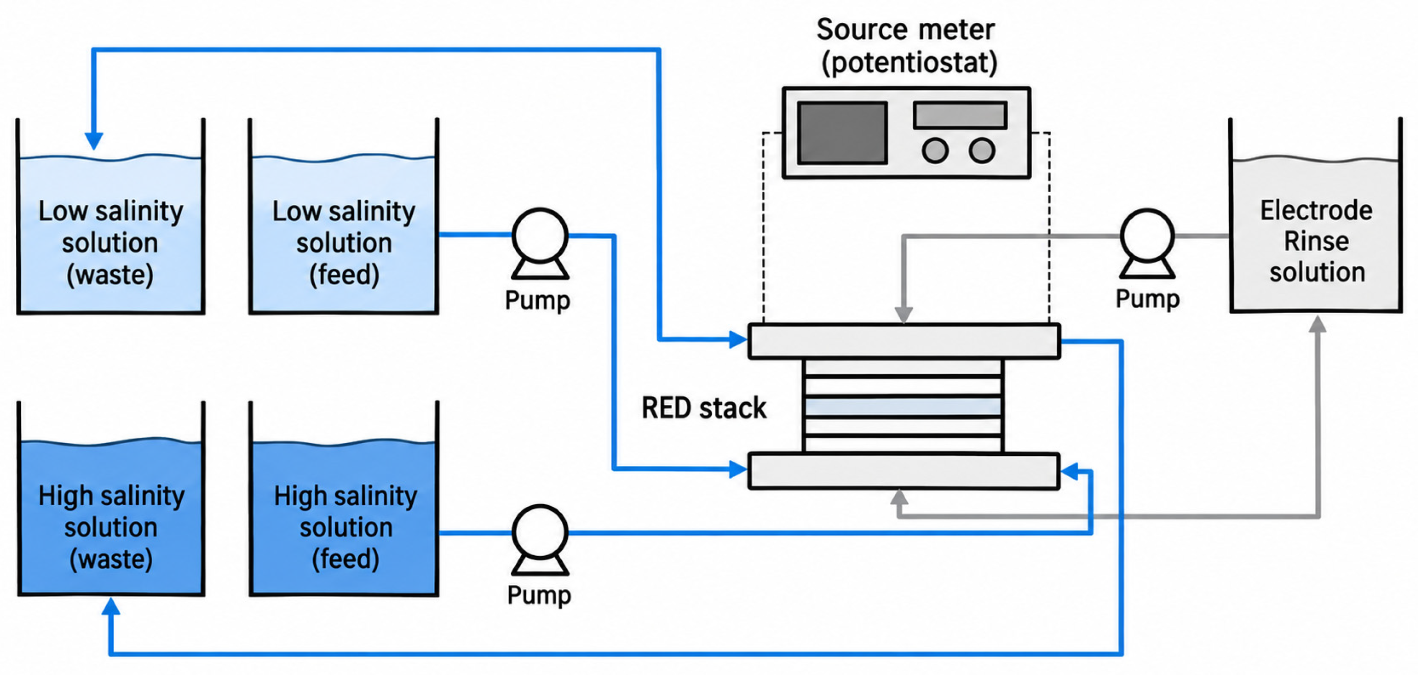
Nanofluidic and two-dimensional membranes can produce substantially higher laboratory-scale power densities than conventional RED membranes. A graphene-based RED device reported 39% conversion efficiency and 27 W/m2 at room temperature, with 126 W/m2 projected at 47 °C [108]. Reviews of two-dimensional membranes describe values well above conventional membrane performance, but most remain far from practical stack-scale membrane areas and hydraulic conditions [20,109]. Salinity-gradient solar ponds represent a separate thermal use of salinity stratification rather than membrane RED/PRO; selected hybrid solar-pond systems reviewed in Ref. [110] reach multi-megawatt scale, but those values are not RED/PRO stack outputs. For membrane-based salinity-gradient generation, cost, fouling, internal resistance, and scale-up remain the dominant commercialization constraints.
Synthesis. Advanced laboratory membranes can exceed frequently discussed reference densities, but the natural-water RED pilot [29] reported around 0.35 W/m2 gross output, 0.25 W/m2 net initially, and around 0.10 W/m2 net after hydraulic pressure-drop losses increased. Different membrane-area definitions and hydraulic requirements prevent direct transfer of nanopore power densities to field stacks. Membrane cost, fouling, and feed pretreatment remain key barriers. For PRO with river water and seawater, module-scale and net-energy analyses indicate that positive net power is unlikely with current membranes [106].
4.4.2. Microbial Fuel Cell (MFC) Systems
Operating principle and applications. In a microbial fuel cell, electroactive bacteria on the anode oxidize organic matter and transfer electrons to the electrode, either directly or through mediators. The electrons flow through the external circuit to the cathode, where they usually reduce oxygen, while protons migrate through the electrolyte or a membrane. Because the practical open-circuit voltage of a single cell is below about 0.8 V, cells are stacked to reach useful voltages. MFCs are applied to wastewater treatment, sediment-powered remote sensors, and biosensors (indicative TRL 4–6).
MFCs convert chemical energy in biodegradable organic matter into low-voltage electrical energy through the metabolism of electroactive microorganisms, while also enabling wastewater-treatment functions and requiring no rotating mechanical converter [9,21,22,23]. Reported power density depends strongly on reactor architecture, electrode area definition, substrate, inoculum, and operating conditions. Earlier reviews span milliwatts per square meter to watts per square meter [9,23], while Ref. [21] summarizes representative cases around 2.44–3.31 W/m2 with Coulombic efficiencies up to 55.6%. A broader review published in the 2026 volume of Renewable and Sustainable Energy Reviews reports 0.2–4.3 W/m2, Coulombic efficiencies up to 90%, and internal resistances as low as 30 Ω across optimized stacked designs [22]. These maxima come from different reported configurations and should not be interpreted as simultaneous performance of a single MFC.
Wastewater-treatment performance is an important co-benefit of MFCs. Ref. [21] summarizes study-specific maxima, including chemical oxygen demand (COD) removal up to 93.7%, total organic carbon removal up to 70%, and antibiotic removal up to 98%; these maxima originate from different operating conditions and need not coincide with the highest electrical output. Organic-waste reviews also report unusually high substrate-specific power densities, including approximately 8314–25,195 mW/m2 for selected waste streams and an exceptional value of 88,990 mW/m2 for a nonconventional configuration [111]. These values represent high-end configuration-specific reports rather than typical MFC performance. They could not be traced to primary studies and are therefore excluded from the ranges in Table 3 (Table A3).
The principal barrier to wider MFC deployment is scale-up. Despite extensive laboratory and pilot research, widespread industrial use remains limited by low absolute power production, membrane and electrode cost, long start-up times, mass-transfer limitations, and long-term stability of microbial communities [21,22,23].
Synthesis. MFCs combine wastewater treatment with power generation, with review-reported densities of roughly 0.2–4 W/m2 in selected configurations and higher values only in specific configurations. Low absolute power, electrode cost, and long-term stability limit scale-up, and life-cycle evidence does not yet show a clear environmental advantage over anaerobic treatment [112].
5. Comparative Discussion
5.1. Cross-Technology Performance Comparison
Power output and conversion efficiency are compared separately. Table 3 gives selected source-specific output values and ranges where comparable, grouped by output basis (per device, per unit area or per unit volume), rather than a single representative value; Table 4 gives conversion efficiencies together with the definition of efficiency used in each case. Because many studies report only their best operating point, the upper end of each range indicates demonstrated capability under favorable conditions rather than typical field performance. Evidence levels follow Section 2.4. Figure 9 illustrates selected source-specific absolute outputs with distinct markers for laboratory electrical measurements, measured shaft power, a validated-model prediction, and field electrical operation; it is not a technology ranking.
Table 3.
Selected source-specific absolute and normalized outputs. Values with distinct denominators or evidence levels are not pooled into a single technology ranking.
Table 4.
Reported conversion efficiencies and related performance metrics, grouped by physical meaning. Each metric is defined by its numerator and denominator; metrics in different groups are not equivalent. (A) Energy conversion efficiency of a single stage (stage output energy/stage input energy). (B) Energy conversion efficiency of a complete system (electrical output/primary resource input). (C) Charge-based efficiency (not an energy efficiency). (D) Normalized indicators and reference ratios (not equivalent to electrical-conversion efficiencies). (E) Hydrodynamic capture and extraction ratios (not electrical conversion efficiencies).
Figure 9.
Selected reported absolute-output benchmarks classified by the type of output and evidence. Markers are individual cited operating points (not means or rankings); thermoacoustic, MHD, and other technologies are not compared by efficiency or resource input in this figure. Electrical laboratory measurements (E2), measured shaft outputs (E3), modeled OWC electrical output (E4), and operational TEG electrical output (E1) are distinguished visually. Source, identified in the figure by author and year: Liu et al. (2021) [39], Eugeni et al. (2020) [38], Roy et al. (2022) [47], Satpute et al. (2021) [54], Zhu et al. (2023) [90], Wu et al. (2014) [88], Bi et al. (2017) [89], Rusin et al. (2021) [74], Renuke et al. (2024) [30], Ding et al. (2025) [77], and NASA (2020) [103].
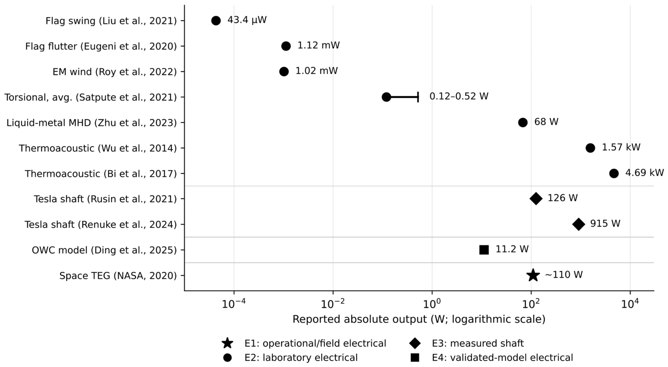
Comparing Table 3 and Table 4 shows that efficiency and power output must be judged separately. Several low-power devices report very high efficiencies: inertial harvesters exceed 85% mechanical-to-electrical conversion while delivering mW-level average power, because the efficiency refers only to the transduction stage. Conversely, thermoelectric generators operate at a few percent efficiency yet deliver 100 W-class output when a large heat flow is available. Only metrics within the same group of Table 4, with compatible resource and normalization references, are comparable: single-stage efficiencies (group A) exclude upstream and downstream losses, whole-system efficiencies (group B) include them, Coulombic efficiency (group C) measures charge rather than energy recovery, the factors in group D are normalized indicators rather than efficiencies, and the ratios in group E describe hydrodynamic capture or extraction rather than electrical conversion. Similarly, normalized power densities in Table 3 are compared only when they share the same normalization reference (whole device, active material, membrane, electrode, or swept area). Efficiency therefore indicates how well an available resource is used, whereas power output indicates which applications a technology can serve.
The classification identifies numerous E2 laboratory electricity results and a smaller set of field, pilot, or extended-duration records. Examples include a river demonstration of hydrokinetic extraction [57], a 60-day triboelectric device study [45], grid-connected OWC operation [78], a natural-water RED pilot [29], commercial/space TEG service [103], and reported point-absorber sea trials [6,16]. These do not all measure the same output or satisfy identical test-duration criteria; an exact number of field-demonstrated pathways is therefore not asserted. Evidence gaps remain especially pronounced for net electrical yield, reliability, and normalized cross-technology performance.
Most aerodynamic Family I harvesters remain in the microwatt-to-milliwatt range and are constrained by resonance, lock-in bandwidth, and small device scale. Torsional/base-motion harvesters are a separate oscillatory subgroup and can reach higher output through inertial or mechanical-rectification architectures. Across Family I, the strongest recurring application remains distributed low-power electronics, sensing, and condition monitoring.
Family II and selected Family III systems reach higher absolute output in some studies, but the evidence includes measured electrical power, shaft power, experimentally validated model predictions, and concept-scale results. System-level relevance should therefore be judged from output type, parasitic losses, durability, and validation level rather than headline magnitude alone.
Electrochemical converters are better compared through areal power density, membrane/reactor losses, and scale-up behavior than by direct comparison with watt-based mechanical harvesters. RED and MFC performance remains strongly influenced by membrane cost, internal resistance, fouling, substrate/feed composition, and stack-scale losses.
Hybridization is a recurring strategy across the reviewed systems. Piezoelectric–electromagnetic, triboelectric–electromagnetic, and VIV–galloping designs can increase output or broaden operating bandwidth, but reported percentage gains are not directly comparable because studies use different metrics and baselines.
Mechanical rectification is one route for coupling low-frequency oscillation to conventional generators. The CCAM example in our previous work [37] illustrates this architecture but remains a numerical design-integration study rather than an electrical-performance benchmark.
5.2. Application Niches with Demonstrated Advantages
Direct, controlled comparisons between a bladeless system and the conventional alternative serving the same application are rare in the reviewed literature. Table 5 therefore lists the application niches in which an advantage has been claimed, together with the strength of the supporting evidence.
Table 5.
Application niches in which an advantage of bladeless and low-moving-part systems over conventional alternatives has been claimed, with the supporting evidence.
Across these niches, the advantage of bladeless and low-moving-part systems arises from the application constraint rather than from superior conversion efficiency. These systems compete where rotating machinery is impractical, unsafe, or costly to maintain, or where the resource is too weak or too dispersed for a turbine. Outside such constraints, conventional bladed turbines generally remain more efficient and more mature.
5.3. Energy Harvesting Versus Vibration Suppression
Flow-induced vibration is the energy source of the Family I harvesters but a hazard for structures such as long-span bridges, where the engineering aim is suppression. The two fields share the same physics, including vortex shedding, lock-in, and aeroelastic instability, and bridge-aerodynamics studies show how strongly small geometric or flow-control changes alter the response. Inclined railings acting as passive vortex generators completely suppressed both vertical and torsional VIV of a closed-box girder model by reducing streamwise velocity fluctuations and their spanwise correlation in the wake [115]. Active spanwise suction has been used to control vortex shedding behind a bridge section in delayed detached-eddy simulations [116], and a leading-edge jet combined with trailing-edge suction reduced fluctuating aerodynamic forces on a box girder by moving unsteady flow structures farther downstream [117].
For energy harvesting, these results suggest the inverse design rule: features that increase the strength and spanwise coherence of vortex shedding raise the extractable power, whereas unintended wake disruption by mounts, adjacent structures, or surface details can sharply reduce it. Transfer of the findings is limited, however. Suppression studies concern large, stiff structures at high Reynolds numbers and aim to eliminate the response, whereas harvesters are small, lightly damped, and must remain in lock-in while extracting energy; the electrical damping introduced by the transducer itself changes the response. Suppression studies therefore indicate which flow mechanisms matter, but not the quantitative performance of a harvester.
6. Practical Implementation Challenges and Scalability
The reviewed technologies face practical constraints that are often less visible in short laboratory or numerical studies. These constraints help explain why peak reported performance does not directly translate into field energy yield or commercial readiness.
6.1. Technical Implementation Constraints
Durable operation. Outdoor flow-induced vibration and triboelectric harvesters are exposed to moisture, temperature cycling, dust, contamination, and surface degradation, while marine and hydrokinetic systems additionally face corrosion, biofouling, and debris loading [2,14,15,64,70]. Long-duration field data remain much less common than laboratory demonstrations.
Limited operational range. Many Family I devices depend on resonance, lock-in, flutter onset, or other flow-dependent instabilities, so performance decreases outside the designed operating region [11,12,13,34,66]. Nonlinear, bistable, multistable, and self-adjusting approaches can broaden the usable range but add mechanical and modeling complexity.
Comparability and standardization. Reported performance is normalized in different ways, including per unit area, volume, or mass, and studies also use different efficiency definitions and test conditions. These differences make direct cross-technology comparisons difficult and complicate technology selection.
Net electrical output after conditioning. Raw harvester output often requires rectification, impedance matching, storage, and power-management electronics; high-voltage/low-current or irregular AC outputs can therefore deliver substantially less usable net power than their unconditioned headline values [47,65]. At a larger scale, auxiliary loads and system penalties can also be important, as illustrated by the automotive TEG case in Ref. [102].
Array scale-up and interactions. Marine and wave-energy deployment introduces hydrodynamic interactions that are absent from isolated-device tests, so commercial feasibility cannot be inferred solely from single-unit optimization. Array spacing, coordinated control, mooring, survivability, and maintenance become system-level design variables [85].
Materials and component cost. Salinity-gradient and MFC systems are strongly affected by membrane cost and durability [8,20,21,22,23]. Piezoelectric and triboelectric devices also face material-selection and environmental-stability constraints [10,14,15]. Cost assessments should therefore be made at system level rather than inferred from transducer output alone.
Addressing these limitations requires advances in flexible and durable materials, nonlinear and multistable structures, standardized performance reporting, multiphysics modeling, drivetrain assessment, and long-duration field validation under realistic operating conditions.
6.2. Technology Readiness, Maintenance, and Cost
Table 6 places each pathway on the nine-level technology readiness level (TRL) scale, from basic principles observed (TRL 1) to a system proven in operational use (TRL 9). The values are indicative assessments based on the highest demonstration found in the reviewed literature, not formal readiness audits. Linking each pathway to its applications (Table 5), Table 6 compares the largest demonstrated scale, the longest reported test, whether net electrical output is reported, the maintenance burden, and the evidence still missing. Readiness is inferred only from demonstrated scale and duration, not from peak laboratory performance, and “not reported” marks missing evidence rather than poor performance.
Table 6.
Structured synthesis of demonstrated scale, testing duration, net electrical output, maintenance, and readiness for each pathway. “Not reported” identifies missing evidence.
Field evidence is uneven rather than absent: operational grid-connected OWCs [78], long-duration thermoelectric service [103], marine point-absorber trials [6,16], natural-water RED pilots [29], and hydrokinetic river demonstrations [57] represent different degrees and types of deployment. The Mutriku study reported an average capacity factor near 0.11 [78], and wave-energy cost estimates vary by device and site [118]. In the RED pilot, net power density declined from approximately 0.25 to 0.10 W/m2 as stack pressure losses rose, whereas gross output remained around 0.35 W/m2 [29]. Because operating boundaries and denominators differ, neither laboratory peaks nor a single site imply a comparable commercial technology level. Material and manufacturing costs remain central to TEG economics [104]. Quantitatively, a techno-economic review reports levelized costs of wave energy mostly between about EUR 0.30 and 1.20/kWh, with oscillating-water-column cases at about EUR 1.50–2.17/kWh depending on discount rate, compared with about USD 0.06–0.38/kWh for solar and USD 0.10–0.56/kWh for offshore wind in the same review [118]. For thermoelectric generators, material costs alone are too high for typical power generation below about 135 °C, whereas above about 275 °C many bulk thermoelectric materials can achieve costs below USD 1/W [104]. No comparable cost data were found for the Family I harvesters, Tesla turbines, or MHD or electrokinetic generators.
6.3. Life-Cycle and Sustainability Assessment
The absence of exposed blades is often cited as an environmental benefit, for example, through lower collision risk for birds and bats and lower noise. These benefits are plausible but have not been measured for most bladeless devices. A sustainability claim also requires accounting for embodied materials, operation, and end of life, and the reviewed pathways raise several specific concerns.
Hazardous and persistent materials. Many piezoelectric harvesters use lead-based PZT ceramics; lead-free alternatives exist but generally offer lower electromechanical performance [119]. Triboelectric harvesters frequently use fluoropolymer layers such as FEP and PTFE, which are persistent materials whose end-of-life handling has not been assessed in the reviewed studies [14,15,44].
Critical raw materials. Electromagnetic harvesters, linear alternators, and MHD channels commonly rely on rare-earth permanent magnets, and the most widely used thermoelectric materials are tellurium-based, which affects both cost and supply security [104].
Membranes and chemicals. Reverse electrodialysis and MFC systems depend on ion-exchange membranes, some of them perfluorinated, together with the chemicals used for membrane cleaning and feed pretreatment [8,20,21,22,23].
Marine and atmospheric effects. Marine converters introduce mooring footprints, installation noise, and antifouling coatings [2,6,70], while gas-phase corona EHD devices can generate ozone, which is relevant to the actuation context in Section 4.3.3.
Published life-cycle assessments (LCAs) were found for only a few of the reviewed pathways. For ocean energy, a comparative LCA found that impacts are dominated by the materials and manufacturing of the structure and that results depend strongly on device design and site [120]. For MFCs, an LCA of wastewater treatment found no significant environmental advantage over conventional high-rate anaerobic treatment with biogas recovery, mainly because of reactor materials [112]. No LCA was found for flow-induced vibration, triboelectric, or electrostatic wind harvesters. For distributed sensing, the main sustainability argument is the avoided replacement of primary batteries; the net benefit depends on the harvester’s service life relative to the battery it replaces and on the embodied impact of its power-management electronics. Comparative LCA against battery-powered and small-turbine alternatives is therefore identified as a research priority (Section 6.4).
6.4. Pathway-Specific Research Gaps and Priorities
Table 7 identifies the most limiting gap for each pathway group, the development that would address it, and its priority. Priority reflects how directly the gap blocks practical deployment rather than its scientific interest.
Table 7.
Pathway-specific research gaps and prioritized developments.
7. Conclusions
This review synthesized 121 cited sources spanning eighteen bladeless and low-moving-part technology pathways. The central finding is that “bladeless” does not define a single physical mechanism or performance class. The literature instead spans oscillatory harvesters, boundary-layer turbomachinery, marine wave converters, thermoacoustic and electromagnetic-fluid systems, thermoelectric generators, and electrochemical converters. Meaningful comparison therefore requires explicit separation of absolute electrical output, shaft or acoustic power, areal and volumetric power density, conversion efficiency, normalized metrics, and modeled or projected values.
Family I—oscillatory and flow-induced harvesters—contains both flow-excited devices and torsional/base-motion systems. Aerodynamic piezoelectric, electromagnetic, triboelectric, electrostatic, flutter, galloping, and VIV harvesters are predominantly low-power distributed technologies, whereas selected motion-rectified torsional devices reach higher output. Their advantages are compactness and compatibility with sensing, monitoring, and IoT applications; their limitations include narrow dynamic operating regions, small recoverable energy at device scale, environmental durability, and limited long-duration field evidence.
Family II and selected Family III technologies provide pathways to larger absolute output or system-level conversion. OWCs and point absorbers exploit ocean-wave motion, Tesla turbines occupy specialized boundary-layer turbomachinery niches, thermoacoustic generators have demonstrated kilowatt-class electrical output [88], and experimental MHD systems have demonstrated direct conversion in conducting fluids [90]. TEGs are mature in selected waste-heat and remote-power niches [4,18]. In each case, measured electrical output must remain distinct from shaft power, acoustic power, model predictions, and projected system-scale performance.
Family IV systems extend bladeless conversion beyond mechanical and thermal processes. Reverse electrodialysis and related salinity-gradient systems can exploit the free energy of mixing saline streams, while microbial fuel cells can combine wastewater treatment with low-voltage electricity generation. Both classes remain constrained by membrane cost, fouling, internal resistance, stack-scale losses, and the difficulty of translating favorable laboratory power densities into reliable full-scale output. The unusually high values reported for some nanofluidic membranes and waste-fed microbial fuel cells should therefore be interpreted as configuration-specific upper bounds rather than typical commercial performance.
Evidence grading shows that many oscillatory-harvester benchmarks are laboratory-only, while deployment evidence is unevenly distributed across OWC, TEG, RED, point-absorber, and hydrokinetic pathways. The type of field observation differs between studies, and long-duration net electrical yield is uncommon. Comparative life-cycle assessments exist for only a minority of pathway groups. Demonstrated advantages consequently arise from specific constraints, such as low-power sensing, remote operation, hydraulic resource recovery, or coastal integration, rather than from a general efficiency advantage over conventional turbines.
Across all four families, recurring research needs include broader operating range, durable materials, coupled multiphysics design, realistic accounting of conditioning and auxiliary losses, explicit reporting of the normalization basis, and long-duration field validation, together with comparative life-cycle assessment against the conventional alternatives they would replace. The evidence does not support treating bladeless and low-moving-part systems as a single replacement class for conventional turbines. Their value is better understood as a diverse set of complementary conversion approaches whose suitability depends on the energy source, required power level, operating environment, maintenance constraints, and system scale.
Author Contributions
Conceptualization, G.S. and N.S.; methodology, G.S., S.Y. and M.S.; literature search and data extraction, G.S. and N.S.; formal analysis, G.S. and N.S.; writing—original draft preparation, S.Y. and M.S.; writing—review and editing, G.S., N.S. and S.Y.; supervision, N.S. All authors have read and agreed to the published version of the manuscript.
Funding
This research received no external funding. The APC was funded by the University of Balamand.
Institutional Review Board Statement
Not applicable. No new studies involving human participants or animals were performed by the authors.
Informed Consent Statement
Not applicable.
Data Availability Statement
No new experimental data were created. All data discussed are drawn from the published sources cited in the reference list; the study-level extraction in Appendix A (Table A2) summarizes selected quantitative values and their original sources, together with their evidence levels, and Table A1 lists the search strings used.
Acknowledgments
During the preparation of this manuscript, the authors used ChatGPT (GPT-5; OpenAI, San Francisco, CA, USA; accessed in 2026) to assist with language editing, manuscript organization, reference cross-checking, and preparation or redrawing of selected schematic figures. The authors reviewed and edited the output and take full responsibility for the content of this publication.
Conflicts of Interest
The authors declare no conflicts of interest.
Abbreviations
The following abbreviations are used in this manuscript:
| Abbrev. | Definition |
| ANN | Artificial Neural Network |
| CCAM | Cylindrical Cam Mechanical Conversion |
| CFD | Computational Fluid Dynamics |
| COD | Chemical Oxygen Demand |
| CWR | Capture-Width Ratio |
| DOF | Degree of Freedom |
| EHD | Electrohydrodynamic |
| EM | Electromagnetic |
| EWICON | Electrostatic Wind Energy Converter |
| FEA | Finite Element Analysis |
| FEP | Fluorinated Ethylene Propylene |
| FIV | Flow-Induced Vibration |
| IoT | Internet of Things |
| LCA | Life-Cycle Assessment |
| LCOE | Levelized Cost of Energy |
| MEMS | Micro-Electro-Mechanical Systems |
| MFC | Microbial Fuel Cell |
| MHD | Magnetohydrodynamic |
| MPPT | Maximum Power Point Tracking |
| ORC | Organic Rankine Cycle |
| OWC | Oscillating Water Column |
| PRO | Pressure-Retarded Osmosis |
| PTFE | Polytetrafluoroethylene |
| PTO | Power Take-Off |
| PVDF | Polyvinylidene Fluoride |
| PZT | Lead Zirconate Titanate |
| RED | Reverse Electrodialysis |
| RMS | Root Mean Square |
| RTG | Radioisotope Thermoelectric Generator |
| TEG | Thermoelectric Generator |
| TENG | Triboelectric Nanogenerator |
| TRL | Technology Readiness Level |
| VIV | Vortex-Induced Vibration |
| VIVACE | Vortex Induced Vibration Aquatic Clean Energy |
Appendix A
Table A1.
Database search strings used for each technology pathway (title, abstract, and keyword fields; January 2005–September 2026).
Table A2.
Source-specific evidence register supporting Section 4 and the illustrative comparisons in Table 3. Each entry distinguishes measured, modeled, projected, review-derived, shaft-power, and actuation-only claims; the E1–E5/R labels are defined in Section 2.4. Numerical area/volume denominators are retained only as stated by the original source and are not assumed equivalent across studies.
Table A3.
Review-derived benchmarks and the outcome of tracing them to primary studies.
References
- Wang, J.; Geng, L.; Ding, L.; Zhu, H.; Yurchenko, D. The state-of-the-art review on energy harvesting from flow-induced vibrations. Appl. Energy 2020, 267, 114902. [Google Scholar] [CrossRef] [Scilit]
- Gayathri, R.; Chang, J.-Y.; Tsai, C.-C.; Hsu, T.-W. Wave Energy Conversion through Oscillating Water Columns: A Review. J. Mar. Sci. Eng. 2024, 12, 342. [Google Scholar] [CrossRef] [Scilit]
- Domínguez-Lozoya, J.C.; Domínguez-Lozoya, D.; Cuevas, S.; Ávalos-Zúñiga, R.A. MHD Generation for Sustainable Development, from Thermal to Wave Energy Conversion: Review. Sustainability 2024, 16, 10041. [Google Scholar] [CrossRef] [Scilit]
- He, J.; Li, K.; Jia, L.; Zhu, Y.; Zhang, H.; Linghu, J. Advances in the Applications of Thermoelectric Generators. Appl. Therm. Eng. 2024, 236, 121813. [Google Scholar] [CrossRef] [Scilit]
- Guha, A.; Sengupta, S. A non-dimensional study of the flow through co-rotating discs and performance optimization of a Tesla disc turbine. Proc. Inst. Mech. Eng. Part A J. Power Energy 2017, 231, 721–738. [Google Scholar] [CrossRef] [Scilit]
- Guo, B.; Wang, T.; Jin, S.; Duan, S.; Yang, K.; Zhao, Y. A Review of Point Absorber Wave Energy Converters. J. Mar. Sci. Eng. 2022, 10, 1534. [Google Scholar] [CrossRef] [Scilit]
- Timmer, M.; De Blok, K.; Van Der Meer, T.H. Review on the conversion of thermoacoustic power into electricity. J. Acoust. Soc. Am. 2018, 143, 841–857. [Google Scholar] [CrossRef] [Scilit]
- Tong, X.; Liu, S.; Crittenden, J.; Chen, Y. Nanofluidic Membranes to Address the Challenges of Salinity Gradient Power Harvesting. ACS Nano 2021, 15, 5838–5860. [Google Scholar] [CrossRef] [Scilit]
- Logan, B.E.; Hamelers, B.; Rozendal, R.A.; Schröder, U.; Keller, J.; Freguia, S.; Aelterman, P.; Verstraete, W.; Rabaey, K. Microbial fuel cells: Methodology and technology. Environ. Sci. Technol. 2006, 40, 5181–5192. [Google Scholar] [CrossRef] [Scilit]
- Ali, A.; Ali, S.; Shaukat, H.; Khalid, E.; Behram, L.; Rani, H.; Altabey, W.A.; Kouritem, S.A.; Noori, M. Advancements in piezoelectric wind energy harvesting: A review. Results Eng. 2024, 21, 101777. [Google Scholar] [CrossRef] [Scilit]
- Bakhtiar, S.; Khan, F.U.; Fu, H.; Hajjaj, A.Z.; Theodossiades, S. Fluid Flow-Based Vibration Energy Harvesters: A Critical Review of State-of-the-Art Technologies. Appl. Sci. 2024, 14, 11452. [Google Scholar] [CrossRef] [Scilit]
- Cao, D.; Wang, J.; Guo, X.; Lai, S.; Shen, Y. Recent advancement of flow-induced piezoelectric vibration energy harvesting techniques: Principles, structures, and nonlinear designs. Appl. Math. Mech. 2022, 43, 959–978. [Google Scholar] [CrossRef] [Scilit]
- Wang, J.; Yurchenko, D.; Hu, G.; Zhao, L.; Tang, L.; Yang, Y. Perspectives in flow-induced vibration energy harvesting. Appl. Phys. Lett. 2021, 119, 100502. [Google Scholar] [CrossRef] [Scilit]
- Ren, Z.; Wu, L.; Pang, Y.; Zhang, W.; Yang, R. Strategies for effectively harvesting wind energy based on triboelectric nanogenerators. Nano Energy 2022, 100, 107522. [Google Scholar] [CrossRef] [Scilit]
- Li, J.; Chen, J.; Guo, H. Triboelectric Nanogenerators for Harvesting Wind Energy: Recent Advances and Future Perspectives. Energies 2021, 14, 6949. [Google Scholar] [CrossRef] [Scilit]
- Abbasi, A.; Ghassemi, H. A comparative state-of-the-art review of wave energy converters: Point absorbers, linear absorbers, and hybrid systems. Appl. Energy 2026, 409, 127487. [Google Scholar] [CrossRef] [Scilit]
- Chen, G.; Tang, L.; Mace, B.; Yu, Z. Multi-physics coupling in thermoacoustic devices: A review. Renew. Sustain. Energy Rev. 2021, 146, 111170. [Google Scholar] [CrossRef] [Scilit]
- Sanín-Villa, D. Recent Developments in Thermoelectric Generation: A Review. Sustainability 2022, 14, 16821. [Google Scholar] [CrossRef] [Scilit]
- Ochieng, A.O.; Megahed, T.; Ookawara, S.; Hassan, H. Comprehensive review in waste heat recovery in different thermal energy-consuming processes using thermoelectric generators for electrical power generation. Process Saf. Environ. Prot. 2022, 162, 134–154. [Google Scholar] [CrossRef] [Scilit]
- Ma, X.; Neek-Amal, M.; Sun, C. Advances in Two-Dimensional Ion-Selective Membranes: Bridging Nanoscale Insights to Industrial-Scale Salinity Gradient Energy Harvesting. ACS Nano 2024, 18, 12610–12638. [Google Scholar] [CrossRef] [Scilit]
- Chakma, R.; Hossain, M.K.; Paramasivam, P.; Bousbih, R.; Amami, M.; Toki, G.F.I.; Haldhar, R.; Karmaker, A.K. Recent Applications, Challenges, and Future Prospects of Microbial Fuel Cells: A Review. Glob. Chall. 2025, 9, 2500004. [Google Scholar] [CrossRef] [Scilit]
- Mahmoodi Nasrabadi, A. A detailed survey of microbial fuel cells: Classifications, computational modeling, recent innovations, and emerging applications. Renew. Sustain. Energy Rev. 2026, 226, 116241. [Google Scholar] [CrossRef] [Scilit]
- Obileke, K.; Onyeaka, H.; Meyer, E.; Nwokolo, N. Microbial fuel cells, a renewable energy technology for bio-electricity generation: A mini-review. Electrochem. Commun. 2021, 125, 107003. [Google Scholar] [CrossRef] [Scilit]
- Bernitsas, M.M.; Raghavan, K.; Ben-Simon, Y.; Garcia, E.M.H. VIVACE (Vortex Induced Vibration Aquatic Clean Energy): A New Concept in Generation of Clean and Renewable Energy From Fluid Flow. J. Offshore Mech. Arct. Eng. 2008, 130, 041101. [Google Scholar] [CrossRef] [Scilit]
- Djairam, D.; Morshuis, P.H.F.; Smit, J.J. A novel method of wind energy generation—The electrostatic wind energy converter. IEEE Electr. Insul. Mag. 2014, 30, 8–20. [Google Scholar] [CrossRef] [Scilit]
- González-González, E.; Yáñez, D.J.; Del Pozo, S.; Lagüela, S. Optimizing Bladeless Wind Turbines: Morphological Analysis and Lock-In Range Variations. Appl. Sci. 2024, 14, 2815. [Google Scholar] [CrossRef] [Scilit]
- Xia, C.; Tang, L.; Yin, P.; Aw, K. Multi-directional and multi-modal vortex-induced vibrations for wind energy harvesting. Appl. Phys. Lett. 2024, 125, 203901. [Google Scholar] [CrossRef] [Scilit]
- Backhaus, S.; Swift, G.W. A thermoacoustic-Stirling heat engine: Detailed study. J. Acoust. Soc. Am. 2000, 107, 3148–3166. [Google Scholar] [CrossRef] [Scilit]
- Simões, C.; Vital, B.; Sleutels, T.; Saakes, M.; Brilman, W. Scaled-up multistage reverse electrodialysis pilot study with natural waters. Chem. Eng. J. 2022, 450, 138412. [Google Scholar] [CrossRef] [Scilit]
- Renuke, A.; Traverso, A.; Reggio, F.; Pascenti, M.; Silvestri, P. Performance Investigation of Stator-Less and Blade-Less Radial Expander. J. Eng. Gas Turbines Power 2024, 146, 011014. [Google Scholar] [CrossRef] [Scilit]
- Li, X.; Bi, C.; Li, Z.; Liu, B.; Wang, T.; Zhang, S. A Piezoelectric and Electromagnetic Hybrid Galloping Energy Harvester with the Magnet Embedded in the Bluff Body. Micromachines 2021, 12, 626. [Google Scholar] [CrossRef] [Scilit]
- Zhang, H.; Song, R.; Meng, J.; Li, X.; Sui, W.; Yang, X. A direction-adaptive hybrid piezo-electromagnetic energy harvester based on vortex-induced vibration. Ferroelectrics 2021, 584, 113–120. [Google Scholar] [CrossRef] [Scilit]
- Wang, S.; Liao, W.; Zhang, Z.; Liao, Y.; Yan, M.; Kan, J. Development of a novel non-contact piezoelectric wind energy harvester excited by vortex-induced vibration. Energy Convers. Manag. 2021, 235, 113980. [Google Scholar] [CrossRef] [Scilit]
- Sun, W.; Seok, J. A novel self-tuning wind energy harvester with a slidable bluff body using vortex-induced vibration. Energy Convers. Manag. 2020, 205, 112472. [Google Scholar] [CrossRef] [Scilit]
- Zhang, L.; Meng, B.; Tian, Y.; Meng, X.; Lin, X.; He, Y.; Xing, C.; Dai, H.; Wang, L. Vortex-induced vibration triboelectric nanogenerator for low speed wind energy harvesting. Nano Energy 2022, 95, 107029. [Google Scholar] [CrossRef] [Scilit]
- Zhu, M.; Zhu, J.Y.; Zhu, J.Z.; Zhao, Z.; Li, H.; Cheng, X.; Wang, Z.L.; Cheng, T. Bladeless Wind Turbine Triboelectric Nanogenerator for Effectively Harvesting Random Gust Energy. Adv. Energy Mater. 2024, 14, 2401543. [Google Scholar] [CrossRef] [Scilit]
- Saba, N.; Makhlouf, C.; Raad, A.; Abi Frem, C.; Sabat, M. Design and Numerical Analysis of a Novel Vortex-Induced Vibration Bladeless Wind Turbine with Cylindrical Cam Mechanical Conversion. Energies 2026, 19, 1090. [Google Scholar] [CrossRef] [Scilit]
- Eugeni, M.; Elahi, H.; Fune, F.; Lampani, L.; Mastroddi, F.; Romano, G.P.; Gaudenzi, P. Numerical and experimental investigation of piezoelectric energy harvester based on flag-flutter. Aerosp. Sci. Technol. 2020, 97, 105634. [Google Scholar] [CrossRef] [Scilit]
- Liu, J.; Chen, X.; Chen, Y.; Zuo, H.; Li, Q. Experimental Research on Wind-Induced Flag-Swing Piezoelectric Energy Harvesters. Shock Vib. 2021, 2021, 8496441. [Google Scholar] [CrossRef] [Scilit]
- Nivedhitha, D.M.; Jeyanthi, S.; Rithish, B.; Sai Charan, B.G.; Ravi, S.; Vinayagamurthy, G.; Thiagamani, S.M.K. An experimental analysis of air flow-induced piezoelectric energy harvesting using flexible poly(vinylidene fluoride) nanocomposite films. Discov. Mater. 2025, 5, 12. [Google Scholar] [CrossRef] [Scilit]
- Latif, U.; Dowell, E.; Uddin, E.; Younis, Y.M. Parametric aerodynamic and aeroelastic study of a deformable flag-based energy harvester for powering low energy devices. Energy Convers. Manag. 2023, 280, 116846. [Google Scholar] [CrossRef] [Scilit]
- Tian, H.; Shan, X.; Cao, H.; Xie, T. Enhanced performance of airfoil-based piezoaeroelastic energy harvester: Numerical simulation and experimental verification. Mech. Syst. Signal Process. 2021, 162, 108065. [Google Scholar] [CrossRef] [Scilit]
- Liu, J.; Zuo, H.; Xia, W.; Luo, Y.; Yao, D.; Chen, Y.; Wang, K.; Li, Q. Wind energy harvesting using piezoelectric macro fiber composites based on flutter mode. Microelectron. Eng. 2020, 231, 111333. [Google Scholar] [CrossRef] [Scilit]
- Sun, W.; Ding, Z.; Qin, Z.; Chu, F.; Han, Q. Wind energy harvesting based on fluttering double-flag type triboelectric nanogenerators. Nano Energy 2020, 70, 104526. [Google Scholar] [CrossRef] [Scilit]
- Yue, O.; Zhou, Y.; Wang, X.; Bai, Z.; Zou, X.; Xie, L.; Liu, X. A bladeless wind-tunnel generator based on a flutter-driven triboelectric nanogenerator with on-demand micro-structuring. Nano Energy 2024, 128, 109886. [Google Scholar] [CrossRef] [Scilit]
- Perez, M.; Boisseau, S.; Gasnier, P.; Willemin, J.; Reboud, J. An electret-based aeroelastic flutter energy harvester. Smart Mater. Struct. 2015, 24, 035004. [Google Scholar] [CrossRef] [Scilit]
- Roy, S.; Kabir, M.H.; Salauddin, M.; Halim, M.A. An Electromagnetic Wind Energy Harvester Based on Rotational Magnet Pole-Pairs for Autonomous IoT Applications. Energies 2022, 15, 5725. [Google Scholar] [CrossRef] [Scilit]
- Yong, H.; Chung, J.; Choi, D.; Jung, D.; Cho, M.; Lee, S. Highly reliable wind-rolling triboelectric nanogenerator operating in a wide wind speed range. Sci. Rep. 2016, 6, 33977. [Google Scholar] [CrossRef] [Scilit]
- Fang, D.; Gu, G.; Zhang, W.; Gu, G.; Wang, C.; Zhang, B.; Cheng, G.; Du, Z. A Double-Electrode-Layer Wind-Driven Triboelectric Nanogenerator with Low Frictional Resistance and High Mechanical Energy Conversion Efficiency of 10.3%. Nanoenergy Adv. 2023, 3, 236–246. [Google Scholar] [CrossRef] [Scilit]
- Long, L.; Liu, W.; Wang, Z.; He, W.; Li, G.; Tang, Q.; Guo, H.; Pu, X.; Liu, Y.; Hu, C. High performance floating self-excited sliding triboelectric nanogenerator for micro mechanical energy harvesting. Nat. Commun. 2021, 12, 4689. [Google Scholar] [CrossRef] [Scilit]
- Song, J.; Sun, G.; Zeng, X.; Li, X.; Bai, Q.; Zheng, X. Piezoelectric energy harvester with double cantilever beam undergoing coupled bending-torsion vibrations by width-splitting method. Sci. Rep. 2022, 12, 583. [Google Scholar] [CrossRef] [Scilit]
- Wang, X.; Li, J.; Zhou, C.; Tao, K.; Qiao, D.; Li, Y. Vibration Energy Harvester Based on Torsionally Oscillating Magnet. Micromachines 2021, 12, 1545. [Google Scholar] [CrossRef] [Scilit]
- Luo, A.; Zhang, Y.; Dai, X.; Wang, Y.; Xu, W.; Lu, Y.; Wang, M.; Fan, K.; Wang, F. An inertial rotary energy harvester for vibrations at ultra-low frequency with high energy conversion efficiency. Appl. Energy 2020, 279, 115762. [Google Scholar] [CrossRef] [Scilit]
- Satpute, N.; Jugulkar, L.; Jabade, S.; Korwar, G.; Arawade, S. Design and analysis of motion and energy regulating vibration harvester. Proc. Inst. Mech. Eng. Part C J. Mech. Eng. Sci. 2021, 236, 1391–1405. [Google Scholar] [CrossRef] [Scilit]
- Sun, W.; Zhao, D.; Tan, T.; Yan, Z.; Guo, P.; Luo, X. Low velocity water flow energy harvesting using vortex induced vibration and galloping. Appl. Energy 2019, 251, 113392. [Google Scholar] [CrossRef] [Scilit]
- Azimov, U.; Callaghan, J.; Frozanpoor, I.; Hulsmeier, C.; Kwok, C.; Nixon, M.D. A novel vortex-assisted generation system for hydrokinetic energy harvesting from slow water currents. Int. J. Energy Environ. 2018, 9, 317–352. [Google Scholar]
- Kim, E.S.; Sun, H.; Park, H.R.; Shin, S.C.; Chae, E.J.; Ouderkirk, R.; Bernitsas, M.M. Development of an alternating lift converter utilizing flow-induced oscillations to harness horizontal hydrokinetic energy. Renew. Sustain. Energy Rev. 2021, 145, 111094. [Google Scholar] [CrossRef] [Scilit]
- Mahapatra, S.D.; Mohapatra, P.C.; Aria, A.I.; Christie, G.; Mishra, Y.K.; Hofmann, S.; Thakur, V.K. Piezoelectric Materials for Energy Harvesting and Sensing Applications: Roadmap for Future Smart Materials. Adv. Sci. 2021, 8, 2100864. [Google Scholar] [CrossRef] [Scilit]
- Barday, W.; Bahri, Z.S.; Ez-Zabri, S.; Alj, Y.S. An Off-Grid Hybrid Piezoelectric-Electromagnetic Tuning System for Vortex Induced Vibration Bladeless Turbines. In Proceedings of the 2023 7th IEEE Congress on Information Science and Technology (CiSt), Agadir-Essaouira, Morocco, 16–22 December 2023; pp. 342–349. [Google Scholar] [CrossRef] [Scilit]
- Muthalif, A.G.; Hafizh, M.; Renno, J.; Paurobally, M. A hybrid piezoelectric-electromagnetic energy harvester from vortex-induced vibrations in fluid-flow; the influence of boundary condition in tuning the harvester. Energy Convers. Manag. 2022, 256, 115371. [Google Scholar] [CrossRef] [Scilit]
- Elahi, H.; Eugeni, M.; Fune, F.; Lampani, L.; Mastroddi, F.; Romano, G.P.; Gaudenzi, P. Performance Evaluation of a Piezoelectric Energy Harvester Based on Flag-Flutter. Micromachines 2020, 11, 933. [Google Scholar] [CrossRef] [Scilit]
- Zhang, Y.; Li, S.; Wang, W.; Zen, P.; Li, C.; Ye, Y.; He, X. A Review of Electromagnetic Wind Energy Harvesters Based on Flow-Induced Vibrations. Energies 2025, 18, 3835. [Google Scholar] [CrossRef] [Scilit]
- Iqbal, M.; Nauman, M.M.; Khan, F.U.; Abas, P.E.; Cheok, Q.; Iqbal, A.; Aissa, B. Vibration-based piezoelectric, electromagnetic, and hybrid energy harvesters for microsystems applications: A contributed review. Int. J. Energy Res. 2021, 45, 65–102. [Google Scholar] [CrossRef] [Scilit]
- Vidal, J.; Slabov, V.; Kholkin, A.; Santos, M.D.P.S. Hybrid Triboelectric-Electromagnetic Nanogenerators for Mechanical Energy Harvesting: A Review. Nano-Micro Lett. 2021, 13, 199. [Google Scholar] [CrossRef] [Scilit]
- Tao, X.; Wang, T.; Tan, L.; Xu, F.; Chen, A.; Yang, Y.; Zhang, R.; Wang, X. High-Performance Constant Current Triboelectric Nanogenerator for Wind Energy Harvesting and Air Purification. SmartSys 2026, 1, e70012. [Google Scholar] [CrossRef] [Scilit]
- Li, Z.; Zhou, S.; Yang, Z. Recent progress on flutter-based wind energy harvesting. Int. J. Mech. Syst. Dyn. 2022, 2, 82–98. [Google Scholar] [CrossRef] [Scilit]
- Wan, C.; Tian, H.; Shan, X.; Xie, T. Enhanced performance of airfoil-based piezoelectric energy harvester under coupled flutter and vortex-induced vibration. Int. J. Mech. Sci. 2023, 241, 107979. [Google Scholar] [CrossRef] [Scilit]
- Rostami, A.; Armandei, M. Renewable energy harvesting by vortex-induced motions: Review and benchmarking of technologies. Renew. Sustain. Energy Rev. 2017, 70, 193–214. [Google Scholar] [CrossRef] [Scilit]
- Siang, J.; Lim, M.H.; Leong, M.S. Review of vibration-based energy harvesting technology: Mechanism and architectural approach. Int. J. Energy Res. 2018, 42, 1866–1893. [Google Scholar] [CrossRef] [Scilit]
- Rashki, M.; Mojtahedi, A.; Lotfollahi-Yaghin, M.A.; Tamimi, V.; Dadashzadeh, M.; Santos, P.R.; Bernitsas, M.M.; Srinil, N. A review of two-degree-of-freedom vortex-induced vibrations with hydrokinetic energy harvesting applications. Ocean Eng. 2025, 321, 120376. [Google Scholar] [CrossRef] [Scilit]
- Galindo, Y.; Reyes-Nava, J.; Hernandez, Y.; Ibanez, G.R.; Moreira-Acosta, J.; Beltran, A. Effect of disc spacing and pressure flow on a modifiable Tesla turbine: Experimental and numerical analysis. Appl. Therm. Eng. 2021, 192, 116792. [Google Scholar] [CrossRef] [Scilit]
- Li, Y.; Xu, C.; Qin, C.; Zheng, D. Structure Optimization of a Tesla Turbine Using an Organic Rankine Cycle Technology. Fluid Dyn. Mater. Process. 2024, 20, 1251–1263. [Google Scholar] [CrossRef] [Scilit]
- Mazurenko, A.; Kravchenko, V.; Luzhanska, G.; Shavrov, V.; Stanislavov, V. Features of the Boundary Layer Organization in Tesla Disc Turbines. Odes’kyi Politech. Universytet Pr. 2023, 1, 49–53. [Google Scholar] [CrossRef] [Scilit]
- Rusin, K.; Wroblewski, W.; Rulik, S.; Majkut, M.; Strozik, M. Performance Study of a Bladeless Microturbine. Energies 2021, 14, 3794. [Google Scholar] [CrossRef] [Scilit]
- Thomazoni, A.L.R.; Ermel, C.; Schneider, P.S.; Vieira, L.W.; Hunt, J.D.; Ferreira, S.B.; Rech, C.; Gouvêa, V.S. Influence of operational parameters on the performance of Tesla turbines: Experimental investigation of a small-scale turbine. Energy 2022, 261, 125159. [Google Scholar] [CrossRef] [Scilit]
- Shalby, M.M.; Dorrell, D.; Walker, P. Multi-chamber oscillating water column wave energy converters and air turbines: A review. Int. J. Energy Res. 2018, 43, 681–696. [Google Scholar] [CrossRef] [Scilit]
- Ding, Z.; Ning, D.; Mayon, R. Wave-to-wire model for an oscillating water column wave energy converter. Appl. Energy 2025, 377, 124663. [Google Scholar] [CrossRef] [Scilit]
- Ibarra-Berastegi, G.; Sáenz, J.; Ulazia, A.; Serras, P.; Esnaola, G.; Garcia-Soto, C. Electricity production, capacity factor, and plant efficiency index at the Mutriku wave farm (2014–2016). Ocean Eng. 2018, 147, 20–29. [Google Scholar] [CrossRef] [Scilit]
- Mayon, R.; Ning, D.; Zhang, C.; Chen, L.; Wang, R. Wave energy capture by an omnidirectional point sink oscillating water column system. Appl. Energy 2021, 304, 117795. [Google Scholar] [CrossRef] [Scilit]
- Mandev, M.B.; Altunkaynak, A.; Çelik, A. Enhancing wave energy harvesting: Performance analysis of a dual chamber oscillating water column. Energy 2024, 290, 130191. [Google Scholar] [CrossRef] [Scilit]
- Ropero-Giralda, P.; Crespo, A.J.C.; Tagliafierro, B.; Altomare, C.; Domínguez, J.M.; Gómez-Gesteira, M.; Viccione, G. Efficiency and survivability analysis of a point-absorber wave energy converter using DualSPHysics. Renew. Energy 2020, 162, 1763–1776. [Google Scholar] [CrossRef] [Scilit]
- Zhang, B.; Deng, Z.; Miao, Y.; Zhao, B.; Wang, Q.; Zhang, K. Optimization of energy-capture performance of point-absorber wave energy converter. Int. J. Energy Res. 2022, 46, 9444–9455. [Google Scholar] [CrossRef] [Scilit]
- Tan, J.; Polinder, H.; Laguna, A.; Miedema, S. A numerical study on the performance of the point absorber wave energy converter integrated with an adjustable draft system. Ocean Eng. 2022, 254, 111347. [Google Scholar] [CrossRef] [Scilit]
- Yao, G.; Luo, Z.; Lu, Z.; Wang, M.; Shang, J.; Guerrero, J.M. Unlocking the potential of wave energy conversion: A comprehensive evaluation of advanced maximum power point tracking techniques and hybrid strategies for sustainable energy harvesting. Renew. Sustain. Energy Rev. 2023, 185, 113599. [Google Scholar] [CrossRef] [Scilit]
- Vervaet, T.; Stratigaki, V.; De Backer, B.; Stockman, K.; Vantorre, M.; Troch, P. Experimental Modelling of Point-Absorber Wave Energy Converter Arrays: A Comprehensive Review, Identification of Research Gaps and Design of the WECfarm Setup. J. Mar. Sci. Eng. 2022, 10, 1062. [Google Scholar] [CrossRef] [Scilit]
- Haddad, C.; Périlhon, C.; Danlos, A.; François, M.; Descombes, G. Some Efficient Solutions to Recover Low and Medium Waste Heat: Competitiveness of the Thermoacoustic Technology. Energy Procedia 2014, 50, 1056–1069. [Google Scholar] [CrossRef] [Scilit]
- Hamood, A.; Jaworski, A.J.; Mao, X. Development and Assessment of Two-Stage Thermoacoustic Electricity Generator. Energies 2019, 12, 1790. [Google Scholar] [CrossRef] [Scilit]
- Wu, Z.; Yu, G.; Zhang, L.; Dai, W.; Luo, E. Development of a 3 kW double-acting thermoacoustic Stirling electric generator. Appl. Energy 2014, 136, 866–872. [Google Scholar] [CrossRef] [Scilit]
- Bi, T.; Wu, Z.; Zhang, L.; Yu, G.; Luo, E.; Dai, W. Development of a 5 kW traveling-wave thermoacoustic electric generator. Appl. Energy 2017, 185, 1355–1361. [Google Scholar] [CrossRef] [Scilit]
- Zhu, S.; Wang, T.; Jiang, C.; Wu, Z.; Yu, G.; Hu, J.; Markides, C.N.; Luo, E. Experimental and numerical study of a liquid metal magnetohydrodynamic generator for thermoacoustic power generation. Appl. Energy 2023, 348, 121453. [Google Scholar] [CrossRef] [Scilit]
- Pacheco, C.C.; Verissimo, G.L.; Colaço, M.J.; Leiroz, A.J.K.; Cruz, M.E.C.; Santos, H.F.L.; DeFilippo, M.; Quirino, T.S. A computational study on square and helical magnetohydrodynamic generators including applications to a combined power cycle. J. Braz. Soc. Mech. Sci. Eng. 2024, 46, 604. [Google Scholar] [CrossRef] [Scilit]
- Zhao, L.; Peng, A. Wave Energy Conversion Technology Based on Liquid Metal Magnetohydrodynamic Generators and Its Research Progress. Energies 2025, 18, 4615. [Google Scholar] [CrossRef] [Scilit]
- Iranshahi, K.; Defraeye, T.; Rossi, R.M.; Müller, U.C. Electrohydrodynamics and its applications: Recent advances and future perspectives. Int. J. Heat Mass Transf. 2024, 232, 125895. [Google Scholar] [CrossRef] [Scilit]
- Xuan, X.; Li, D. Thermodynamic analysis of electrokinetic energy conversion. J. Power Sources 2006, 156, 677–684. [Google Scholar] [CrossRef] [Scilit]
- Chen, W.; Cai, R.; Wang, L.; Yang, Z.; Wei, R.; Yan, W. Machine learning assisted mechanism modeling for gas phase electrohydrodynamic system. Phys. Fluids 2024, 36(9). [Google Scholar] [CrossRef] [Scilit]
- Masuyama, K.; Barrett, S. On the performance of electrohydrodynamic propulsion. Proc. R. Soc. A 2013, 469, 20120623. [Google Scholar] [CrossRef] [Scilit]
- Leng, J.; Liu, Z.; Zhang, X.; Huang, D.; Huang, J.; Qi, M.; Yan, X. Electrohydrodynamic thrust with no combustion emissions and noises in a centimeter-scale point-to-grid configuration. IOP Conf. Ser. Earth Environ. Sci. 2021, 675, 012015. [Google Scholar] [CrossRef] [Scilit]
- Luo, Y.; Schouten, M.; Shea, H. Increasing the power density of electrohydrodynamic pumps by mapping the fluid landscape. Sci. Adv. 2026, 12, eaeb2623. [Google Scholar] [CrossRef] [Scilit]
- Selvan, K.V.; Hasan, M.N.; Ali, M.M.S. Methodological reviews and analyses on the emerging research trends and progresses of thermoelectric generators. Int. J. Energy Res. 2019, 43, 113–140. [Google Scholar] [CrossRef] [Scilit]
- Chen, W.-H.; Carrera Uribe, M.; Kwon, E.E.; Lin, K.-Y.A.; Park, Y.-K.; Ding, L.; Saw, L.H. A comprehensive review of thermoelectric generation optimization by statistical approach: Taguchi method, analysis of variance (ANOVA), and response surface methodology (RSM). Renew. Sustain. Energy Rev. 2022, 169, 112917. [Google Scholar] [CrossRef] [Scilit]
- Jeng, T.-M.; Tzeng, S.-C.; Yang, B.-J.; Li, Y.-C. Design, Manufacture and Performance Test of the Thermoelectric Generator System for Waste Heat Recovery of Engine Exhaust. Inventions 2016, 1, 2. [Google Scholar] [CrossRef] [Scilit]
- Luo, D.; Sun, Z.; Wang, R. Performance investigation of a thermoelectric generator system applied in automobile exhaust waste heat recovery. Energy 2021, 238, 121816. [Google Scholar] [CrossRef] [Scilit]
- NASA. Multi-Mission Radioisotope Thermoelectric Generator (MMRTG) Fact Sheet; National Aeronautics and Space Administration: Washington, DC, USA, 2020. Available online: https://science.nasa.gov/wp-content/uploads/2024/02/mmrtg-factsheet-updated-5-18-20-1.pdf (accessed on 5 November 2026).
- LeBlanc, S.; Yee, S.K.; Scullin, M.L.; Dames, C.; Goodson, K.E. Material and manufacturing cost considerations for thermoelectrics. Renew. Sustain. Energy Rev. 2014, 32, 313–327. [Google Scholar] [CrossRef] [Scilit]
- Guler, E.; Zhang, Y.; Saakes, M.; Nijmeijer, K. Tailor-made anion-exchange membranes for salinity gradient power generation using reverse electrodialysis. ChemSusChem 2012, 5, 2262–2270. [Google Scholar] [CrossRef] [Scilit]
- Straub, A.P.; Deshmukh, A.; Elimelech, M. Pressure-retarded osmosis for power generation from salinity gradients: Is it viable? Energy Environ. Sci. 2016, 9, 31–48. [Google Scholar] [CrossRef] [Scilit]
- Ju, J.; Choi, Y.; Lee, S.; Park, C.-G.; Hwang, T.; Jung, N. Comparison of Pretreatment Methods for Salinity Gradient Power Generation Using Reverse Electrodialysis (RED) Systems. Membranes 2022, 12, 372. [Google Scholar] [CrossRef] [Scilit]
- Fu, Y.; Guo, X.; Wang, Y.; Wang, X.; Xue, J. An atomically-thin graphene reverse electrodialysis system for efficient energy harvesting from salinity gradient. Nano Energy 2019, 57, 783–790. [Google Scholar] [CrossRef] [Scilit]
- Manikandan, D.; Karishma, S.; Kumar, M.; Nayak, P. Salinity gradient induced blue energy generation using two-dimensional membranes. npj 2D Mater. Appl. 2024, 8, 47. [Google Scholar] [CrossRef] [Scilit]
- Tawalbeh, M.; Javed, R.M.N.; Al-Othman, A.; Almomani, F. Salinity gradient solar ponds hybrid systems for power generation and water desalination. Energy Convers. Manag. 2023, 289, 117180. [Google Scholar] [CrossRef] [Scilit]
- Apollon, W.; Rusyn, I.; Paucar, N.; Hibbert, M.; Kamaraj, S.; Sato, C. Energy Recovery from Organic Wastes Using Microbial Fuel Cells: Traditional and Nonconventional Organic Substrates. Resources 2025, 14, 47. [Google Scholar] [CrossRef] [Scilit]
- Foley, J.M.; Rozendal, R.A.; Hertle, C.K.; Lant, P.A.; Rabaey, K. Life Cycle Assessment of High-Rate Anaerobic Treatment, Microbial Fuel Cells, and Microbial Electrolysis Cells. Environ. Sci. Technol. 2010, 44, 3629–3637. [Google Scholar] [CrossRef] [Scilit]
- Champier, D. Thermoelectric generators: A review of applications. Energy Convers. Manag. 2017, 140, 167–181. [Google Scholar] [CrossRef] [Scilit]
- Skilhagen, S.E.; Dugstad, J.E.; Aaberg, R.J. Osmotic power—Power production based on the osmotic pressure difference between waters with varying salt gradients. Desalination 2008, 220, 476–482. [Google Scholar] [CrossRef] [Scilit]
- Xin, D.; Zhan, J.; Zhang, H.; Ou, J. Control of Vortex-Induced Vibration of a Long-Span Bridge by Inclined Railings. J. Bridge Eng. 2021, 26, 04021093. [Google Scholar] [CrossRef] [Scilit]
- Zhang, H.; Xin, D.; Ou, J. Wake control of vortex shedding based on spanwise suction of a bridge section model using Delayed Detached Eddy Simulation. J. Wind Eng. Ind. Aerodyn. 2016, 155, 100–114. [Google Scholar] [CrossRef] [Scilit]
- Chen, G.-B.; Chen, W.-L.; Kim, K.C. An investigation of aerodynamic characteristics of leading-edge jet and trailing-edge suction set in the bridge main girder. Phys. Fluids 2025, 37, 075175. [Google Scholar] [CrossRef] [Scilit]
- Guo, C.; Sheng, W.; De Silva, D.G.; Aggidis, G. A Review of the Levelized Cost of Wave Energy Based on a Techno-Economic Model. Energies 2023, 16, 2144. [Google Scholar] [CrossRef] [Scilit]
- Rödel, J.; Jo, W.; Seifert, K.T.P.; Anton, E.-M.; Granzow, T.; Damjanovic, D. Perspective on the Development of Lead-free Piezoceramics. J. Am. Ceram. Soc. 2009, 92, 1153–1177. [Google Scholar] [CrossRef] [Scilit]
- Uihlein, A. Life cycle assessment of ocean energy technologies. Int. J. Life Cycle Assess. 2016, 21, 1425–1437. [Google Scholar] [CrossRef] [Scilit]
- Zhang, R.; Dai, W.; Xiang, H.; Chen, J.; Yi, T.; Li, J.; Zhang, J.; Yang, Q.; Xiao, R.; Li, X. Characteristics and driving factors of power generation performance in microbial fuel cells: An analysis based on the CNKI database. Front. Microbiol. 2025, 16, 1620539. [Google Scholar] [CrossRef] [Scilit]
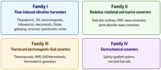
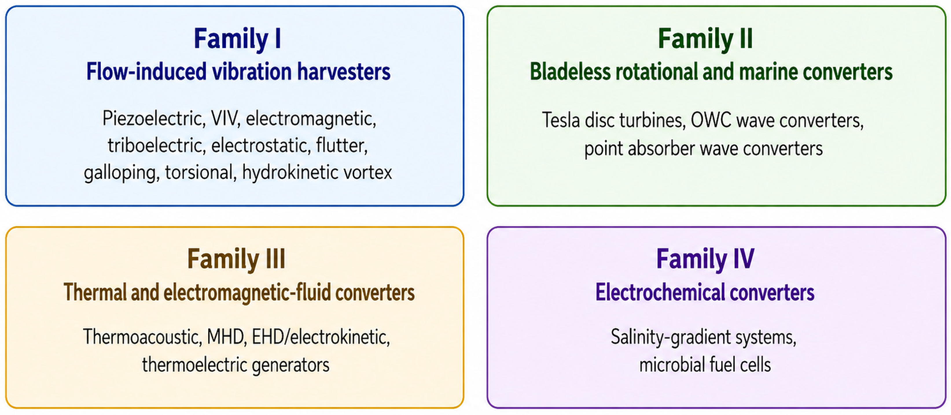
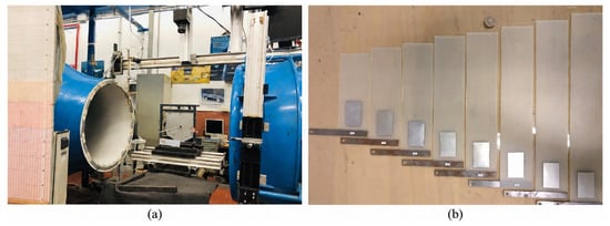
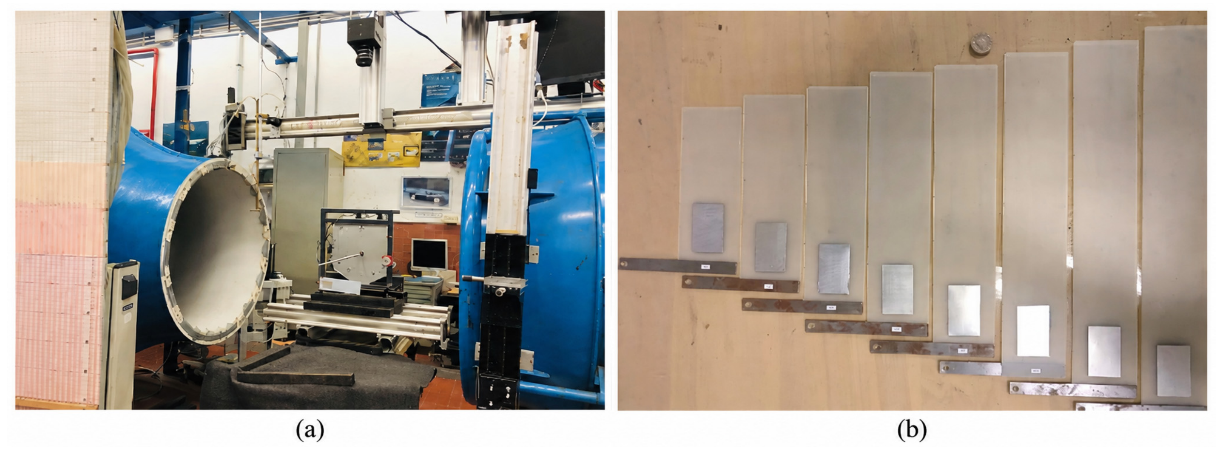
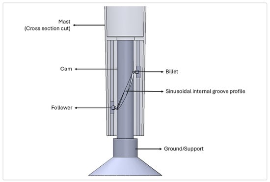
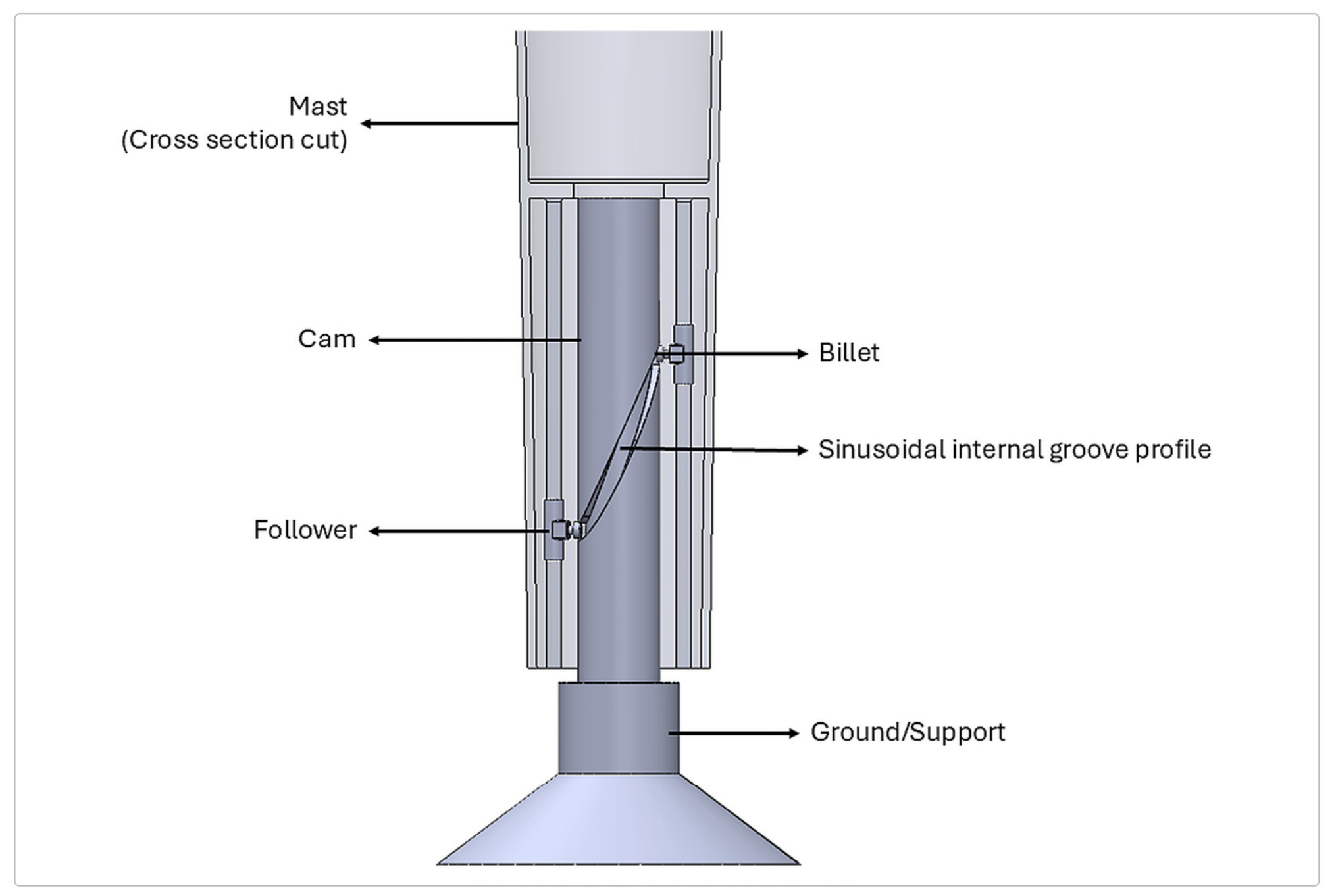
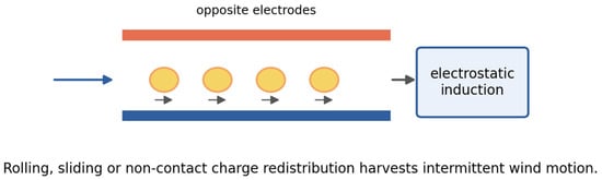
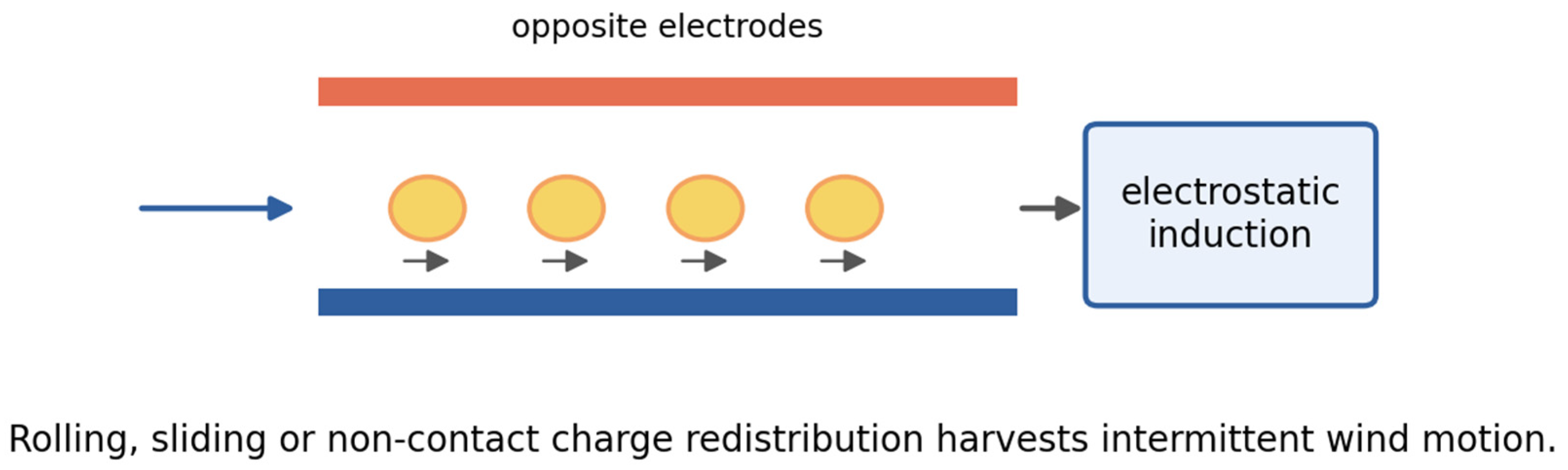
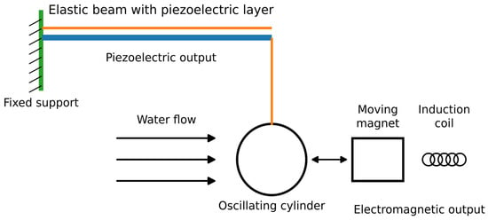
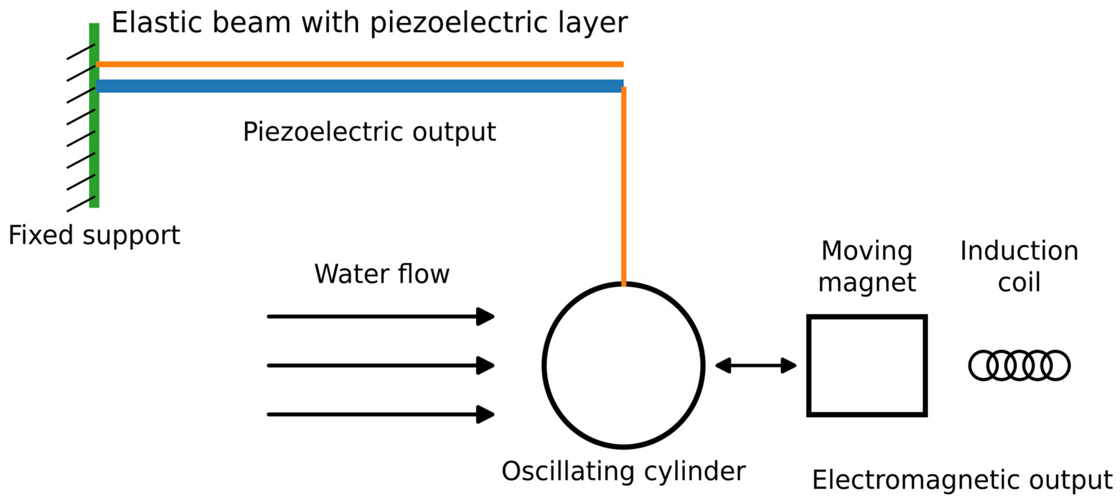
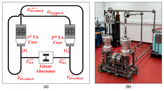
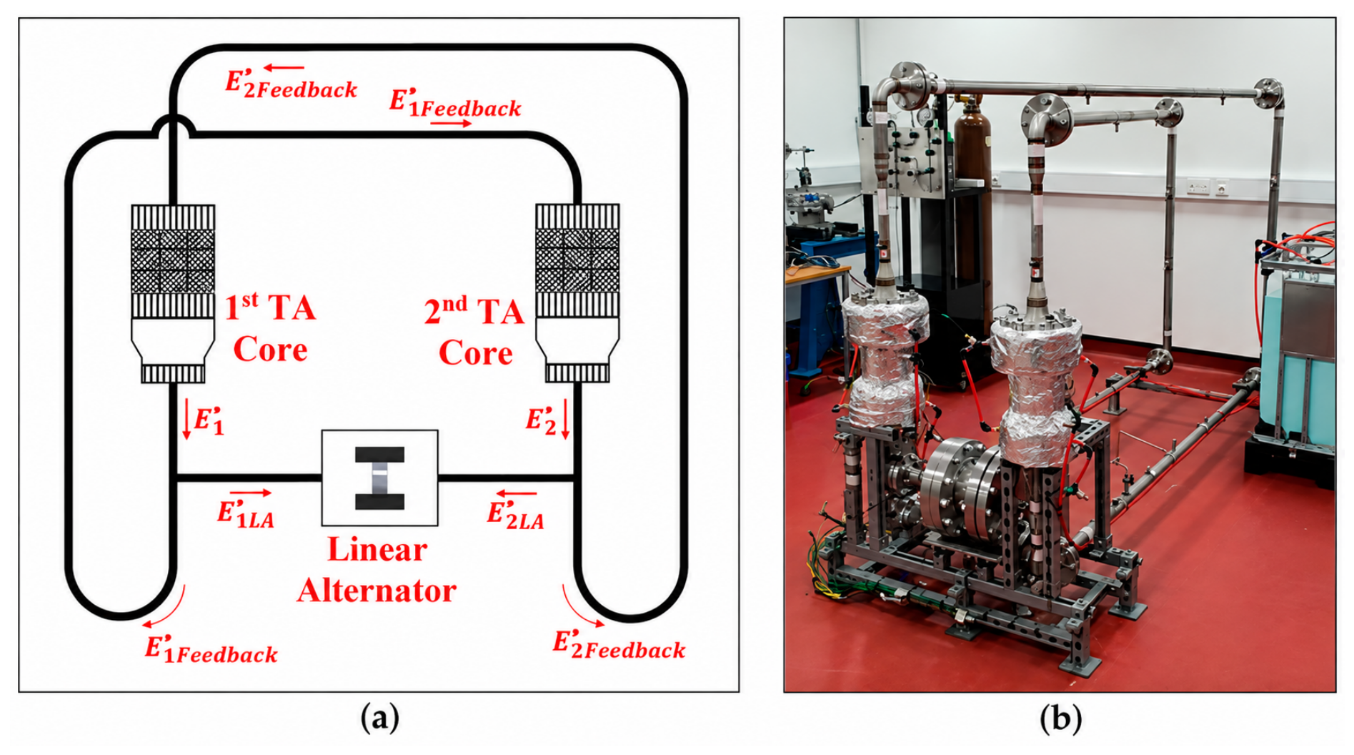
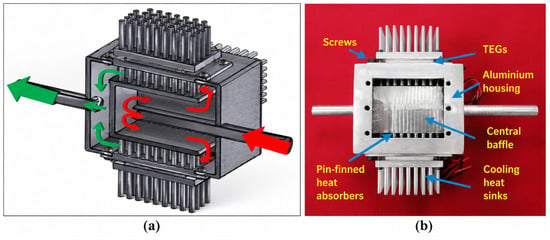
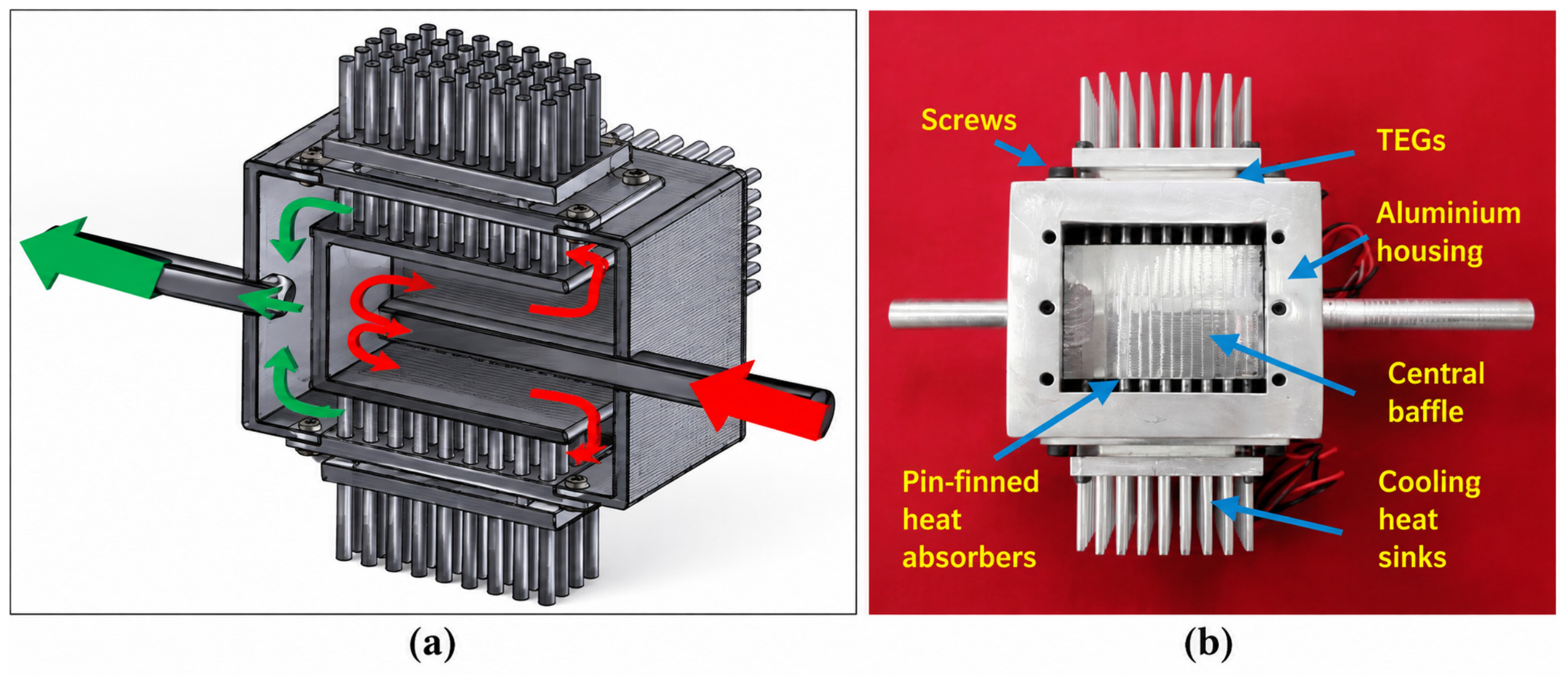

Disclaimer/Publisher’s Note: The statements, opinions and data contained in all publications are solely those of the individual author(s) and contributor(s) and not of MDPI and/or the editor(s). MDPI and/or the editor(s) disclaim responsibility for any injury to people or property resulting from any ideas, methods, instructions or products referred to in the content. |
© 2026 by the authors. Licensee MDPI, Basel, Switzerland. This article is an open access article distributed under the terms and conditions of the Creative Commons Attribution (CC BY) license.