


Abstract
This study compares the hydraulic performance of two centrifugal-pump impellers operating in pump and pump-as-turbine (PAT) modes: a reverse-engineered impeller obtained from a commercial pump by 3D scanning and an impeller developed through a preliminary analytical sizing procedure. Both configurations were evaluated under the same computational framework using OpenFOAM, the Multiple Reference Frame approach, and the k-omega SST turbulence model. Hydraulic performance was assessed through efficiency, pressure, velocity, and turbulent-dissipation fields, complemented by velocity-triangle and parametric sensitivity analyses. The reverse-engineered impeller achieved efficiencies of 90.50% in pump mode and 67% in PAT mode, compared with 79.17% and 50%, respectively, for the analytically designed impeller. Internal-flow analysis indicated that the reverse-engineered geometry produced more uniform velocity and pressure distributions and less extensive turbulent-dissipation regions. Velocity-triangle analysis indicated that its inlet blade angle increases the incidence mismatch in pump mode but reduces residual tangential velocity in PAT operation, favoring angular-momentum transfer. Sensitivity analysis indicated that the dominant geometric parameters depend on the operating direction. The analytical procedure is therefore interpreted as a preliminary sizing approach rather than a validated dual-mode optimization method. Overall, the results indicate that reversible impeller design should consider both operating directions and subsequent CFD-based refinement.
1. Introduction
Reverse engineering has become a suitable tool for the assessment, recovery, and modernization of hydraulic machines, particularly in scenarios where original drawings, geometric parameters, or manufacturing specifications are unavailable or outdated [1]. This methodological approach involves the digital acquisition of the geometry of an existing component, its reconstruction, and the functional reinterpretation of its design logic, with the aim of reproducing its hydraulic behavior while developing higher-performance configurations [2]. In the field of hydraulic turbomachinery, the use of laser scanning, structured light, and photogrammetric techniques has enabled the generation of high-resolution point clouds that can subsequently be transformed into parametric CAD models suitable for numerical simulation, advanced manufacturing, and experimental validation [3]. Based on these tools, Souček et al. demonstrated that the three-dimensional reconstruction of pumps operating as turbines (PATs) can reproduce characteristic curves with adequate consistency through CFD, validating reverse engineering as a reliable approach for hydraulic analysis and impeller redesign [4]. In a complementary manner, Abdulshaheed et al. showed that the digitization and redesigning commercial impellers can be used to reduce pressure losses in networks and enable sustainable distributed generation schemes, reinforcing the idea that digitally recovered geometries can not only be reproduced but also optimized for energy purposes [5].
The growing interest in these methodologies responds to the global need to increase energy efficiency, reduce operating costs, and take advantage of existing hydraulic infrastructure. In this context, PATs represent an attractive alternative for micro- and mini-hydropower applications, energy recovery in drinking water networks, irrigation systems, and low-cost decentralized solutions [6]. Unlike conventional turbines, PATs benefit from the commercial availability of standard pumps, lower acquisition costs, and simplified maintenance [7]. However, their performance under reverse operation depends critically on the impeller geometry, the agreement between the actual operating point and the best efficiency point, and the internal energy losses generated under off-design conditions [8,9].
In this regard, several studies have highlighted the limitations and opportunities of these machines. Nasir et al. identified that one of the main barriers to the industrial expansion of PATs is the uncertainty associated with predicting characteristic curves under variable operating conditions [10]. Similarly, Yang et al. showed that the optimal operating points differ significantly between pump and turbine modes, demonstrating that a machine with high pumping efficiency does not necessarily maximize energy recovery under reverse operation [11]. Bogdanović-Jovanović et al. further demonstrated that reliable turbine-mode characteristic curves and dimensionless correlations are essential for selecting suitable commercial pumps for energy-recovery applications [12].
In parallel with these considerations, recent literature has confirmed that small geometric modifications to the impeller, such as inlet and outlet blade angles, number of blades, meridional length, blade curvature, or trailing-edge configuration, can produce substantial variations in head, transferred power, and overall efficiency [13]. Therefore, impeller redesign has become an emerging research line aimed at improving the dual hydraulic behavior of these machines. Zhang and Song developed an impeller using an inverse design method and reported efficiency improvements associated with a more uniform load distribution [14]. Li et al. demonstrated that modifying the trailing edge favorably alters the vortical structure and reduces internal losses [9]. Jeon et al. confirmed that the number of blades and impeller diameter significantly affect head, efficiency, and hydraulic thrust [15]. In addition, Fordjour et al. demonstrated that the blade inlet angle directly influences pressure, shaft power, entropy generation, and the local distribution of energy losses in PAT operation [16].
From a methodological perspective, the redesign process begins with the accurate capture of the actual geometry through three-dimensional scanning and the generation of high-resolution point clouds. These point clouds are then processed to construct parametric CAD surfaces that faithfully represent the hydraulic passages, hub, shroud, and blade profiles of the impeller [13,17]. This stage is critical, since geometric accuracy directly affects the quality of the computational mesh, numerical convergence, and the reliability of subsequent simulations. Within this framework, inverse-design and parameter-based optimization strategies have demonstrated that the design process should not be limited to maximizing efficiency, but should also improve flow uniformity and control hydraulic losses [14,18]. Recent studies have also shown that integrating hydraulic and structural evaluations improves the operational robustness of impellers subjected to variable loads.
Within this process, the use of computational fluid dynamics (CFD) has become essential for studying both original and redesigned impellers, owing to its ability to resolve in detail the three-dimensional fields of velocity, pressure, turbulence, and wall shear stresses inside the machine [19]. In addition to the conventional analysis of head, power, and efficiency, recent approaches incorporate advanced metrics based on entropy production, turbulence intensity, rotor-stator interaction, and transient behavior away from the best efficiency point. Fordjour et al. demonstrated that entropy production theory enables identification of the regions responsible for the highest hydraulic losses in PATs [16], while Guan et al. revealed that the clocking effect between guide vanes and the volute can produce noticeable efficiency differences [20]. Tang et al. analyzed a pump-turbine over the entire operating range in turbine mode and identified strong instabilities under low-speed and reduced-flow conditions [21]. In a complementary manner, Binama et al. found that flow instabilities increase considerably under off-design conditions and can propagate from the vaneless space to other hydraulic components [22]. Trivedi showed that coherent vortices, rotor-stator interactions, and high-frequency pressure components govern a significant part of energy transfer and operational stability in reversible machines [23,24]. Furthermore, Jin et al. demonstrated that transient start-up strategies may improve stability while simultaneously introducing additional energy losses and pressure fluctuations [25].
Despite the progress reported in recent years, scientific literature still shows a clear gap regarding the systematic comparison between impellers reconstructed by means of reverse engineering and new impeller designs developed for dual operation within the same centrifugal pump. The majority of studies available have treated these subjects separately, focusing on the prediction of commercial pump performance in turbine mode [8,10,11], the geometric optimization of new rotors [9,14,15,16], or the analysis of transient phenomena in reversible hydraulic machines [22,26]. Very few studies have, in the same numerical framework and for both operating modes, compared a geometry taken from an actual machine with an impeller specially designed to improve dual hydraulic performance [27]. Such a comparison is relevant from scientific and engineering perspectives, since it allows the hydraulic limitations inherited from the original commercial geometry to be identified and, at the same time, makes it possible to evaluate whether a new impeller architecture can provide meaningful improvements in efficiency, operational stability, and energy recovery [28].
The main contribution of this paper is the development and assessment of a preliminary analytical sizing procedure for centrifugal-pump impellers considered for pump and turbine operation. The procedure combines analytical and semi-empirical design equations from established centrifugal-pump design references to generate an initial impeller geometry, which is subsequently assessed through CFD. The study also compares the resulting geometry with a reverse-engineered commercial impeller under the same computational framework to identify differences in hydraulic performance and internal-flow behavior in pump and PAT modes. Therefore, the proposed analytical procedure should be regarded as a preliminary engineering design tool rather than as a validated dual-mode optimization methodology.
2. Materials and Methods
2.1. Design
The preliminary design of centrifugal impellers constitutes a critical stage in the development of hydraulic turbomachinery, as it establishes the fundamental geometric configuration and strongly influences the expected hydraulic performance of the machine [29,30]. This process requires the integration of theoretical fluid-mechanics principles, analytical and semi-empirical design equations, and established engineering design practices to define the main impeller and blade dimensions. This process requires the integration of theoretical principles of fluid mechanics with empirical correlations and engineering design practices to define the main impeller and blade dimensions. These parameters subsequently affect the operating efficiency, flow stability, and overall hydraulic behavior of the system [31].
The initial sizing stage of the centrifugal impeller follows a sequential analytical procedure that combines theoretical fluid-mechanics principles with analytical and semi-empirical design equations adopted from established centrifugal-pump design references. This systematic approach starts from the given design conditions—flow rate, head, and rotational speed (Table 1) to iteratively define the macroscopic characteristics of the impeller, ensuring compliance with the specified performance criteria [32]. The determination of the impeller dimensions, such as the inlet and outlet diameters, together with the blade angles, is critically based on Euler’s turbomachinery equation and the velocity triangles, which are essential for understanding energy transfer within the fluid domain [33,34]. These operating conditions are used as the input variables for the sequential preliminary sizing calculations summarized in Table 2.
Table 1.
Input parameter for design of the impeller.
Table 2.
Equations used for preliminary impeller sizing and values obtained for the present study case.
Table 2 summarizes the analytical and semi-empirical design equations used to calculate the main parameters of the centrifugal impeller. The equations are applied sequentially, beginning with the estimation of specific speed and efficiencies and continuing with the determination of characteristic diameters, velocities, and blade angles. The Study Case column reports the values obtained for the operating conditions defined in Table 1, thereby improving the reproducibility of the preliminary sizing procedure.
The expressions summarized in Table 2 are adopted from the cited centrifugal-pump design references and are not treated in the present study as fitted empirical correlations sharing a common calibration dataset. Consequently, a specific original calibration range cannot be consistently assigned to every equation, and such ranges are not explicitly reported for several of the expressions in the original sources. The units of Q, H, and N were therefore used according to the conventions specified for each equation.
Accordingly, the analytical procedure is intended to provide a preliminary sizing of the impeller rather than an optimized geometry. Its purpose is to generate a physically consistent initial design that can subsequently be evaluated and refined using CFD or optimization techniques.
2.2. Blade Curvature Calculation
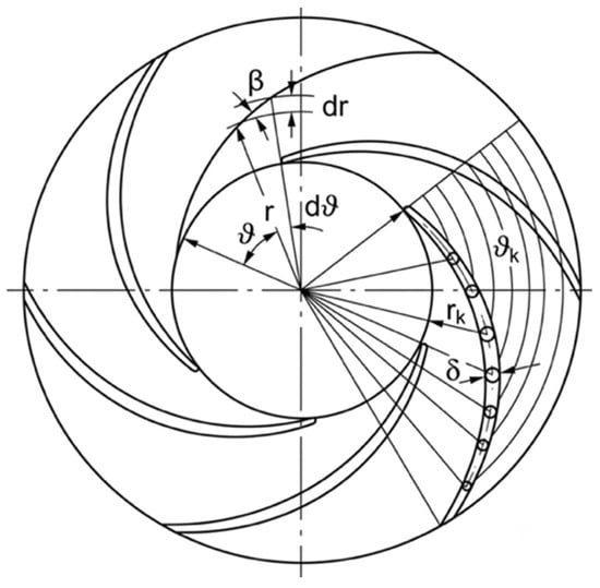
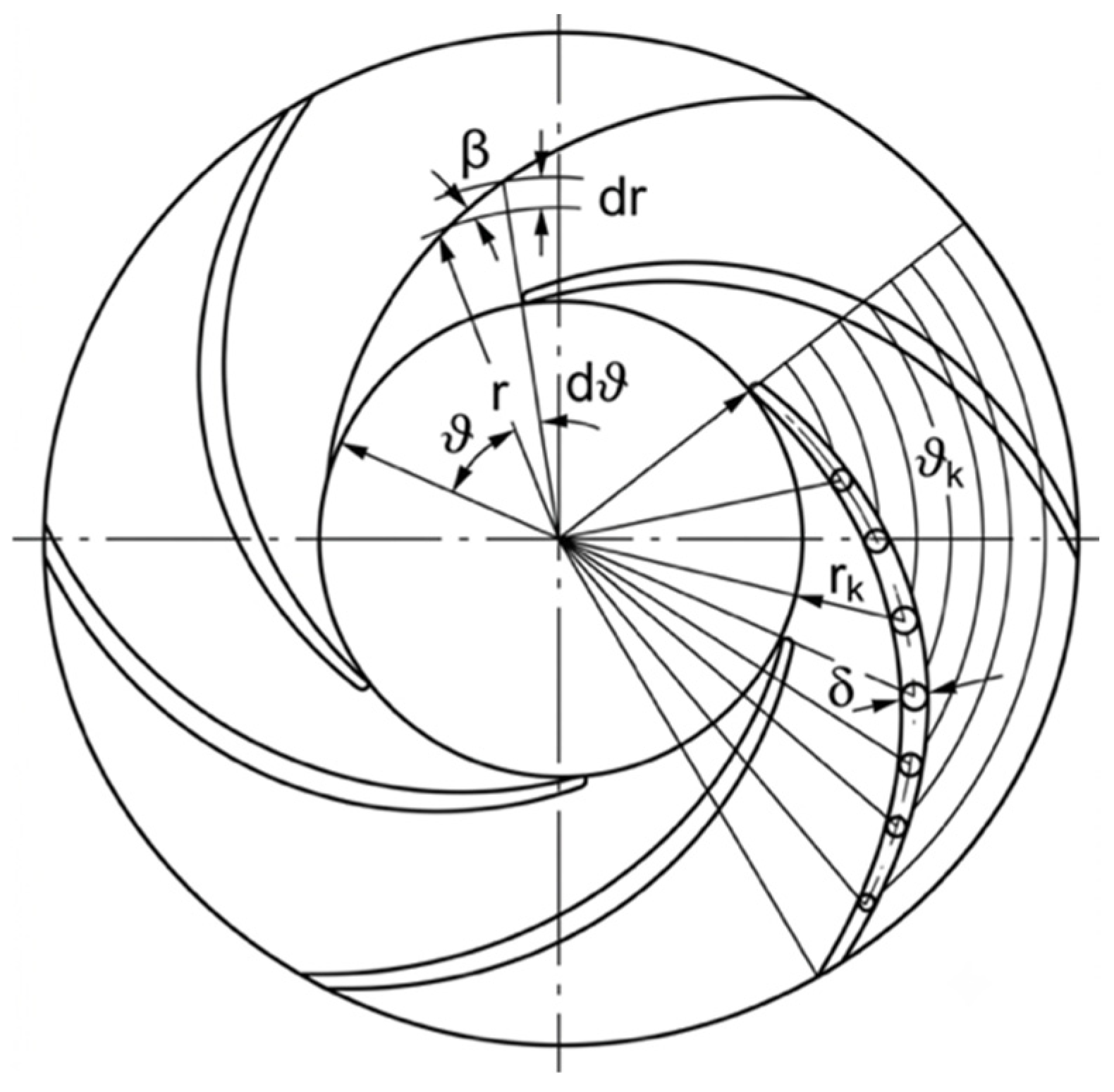
Blade inlet and outlet angles are important variables in impeller design as they directly determine the flow behavior, energy transfer and magnitude of hydraulic losses. These angle deviations may lead to unwanted phenomena such as flow separation, recirculation zones, abrupt pressure gradients and reduced overall performance. Hence, the aim of this study is the exact definition of blade curvature where angular transition from inlet to outlet can be controlled for both operating modes of pump and turbine. The procedure of construct the blade profile is to divide the blade into several radial points, and the local blade angle is known or calculated at each point (see Figure 1).
Figure 1.
Geometric construction of the blade profile in the impeller meridional plane.
In practice, the blade angle β is often derived from discrete values at different radial positions instead of a continuous analytical function. Therefore, the angular position of the profile is calculated via the numerical integration where the accumulated angular coordinate θk is accumulated by the small increments between the adjacent radial points. Each increment in Equation (1) is approximated by the trapezoidal rule, where Bi and Bi+1 are consecutive function values and Δr is the radial step.
The function B(r) is defined in Equation (2), and couples the local blade angle β to the radius r. This expression, which comes from the polar coordinate description of the blade curve, relates angular changes to both radius and local inclination. Thus if B(r) is known at each radial station, the blade trajectory in the meridional plane can be constructed.
To describe the blade angle progression from inlet to outlet, an exponential fitting function (Equation (3)) was implemented so that a smooth variation is obtained avoiding curvature discontinuities. The exponent is a function of the trend (increasing/decreasing) of the angle. βA and A are constants set by the geometric boundary conditions and k sets the rate of change of the distribution.
Alternatively, the local blade angle can be expressed using a normalized transition function [Equations (4) and (5)], where β1 and β2 represent the inlet and outlet blade angles, respectively. The angular variation is controlled by the parameter F, which ranges from 0 to 1 [37]. The normalized coordinate y defines the relative position along the blade profile, while m is a non-dimensional parameter that controls the smoothness of the distribution. This formulation allows the blade curvature to be adjusted progressively while maintaining continuous boundary conditions.
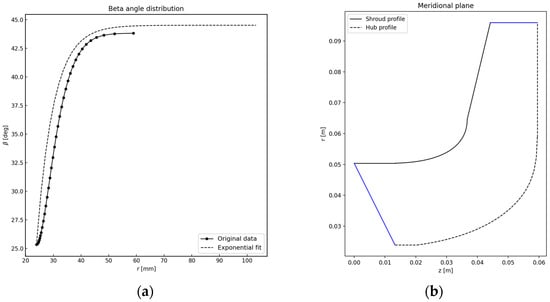
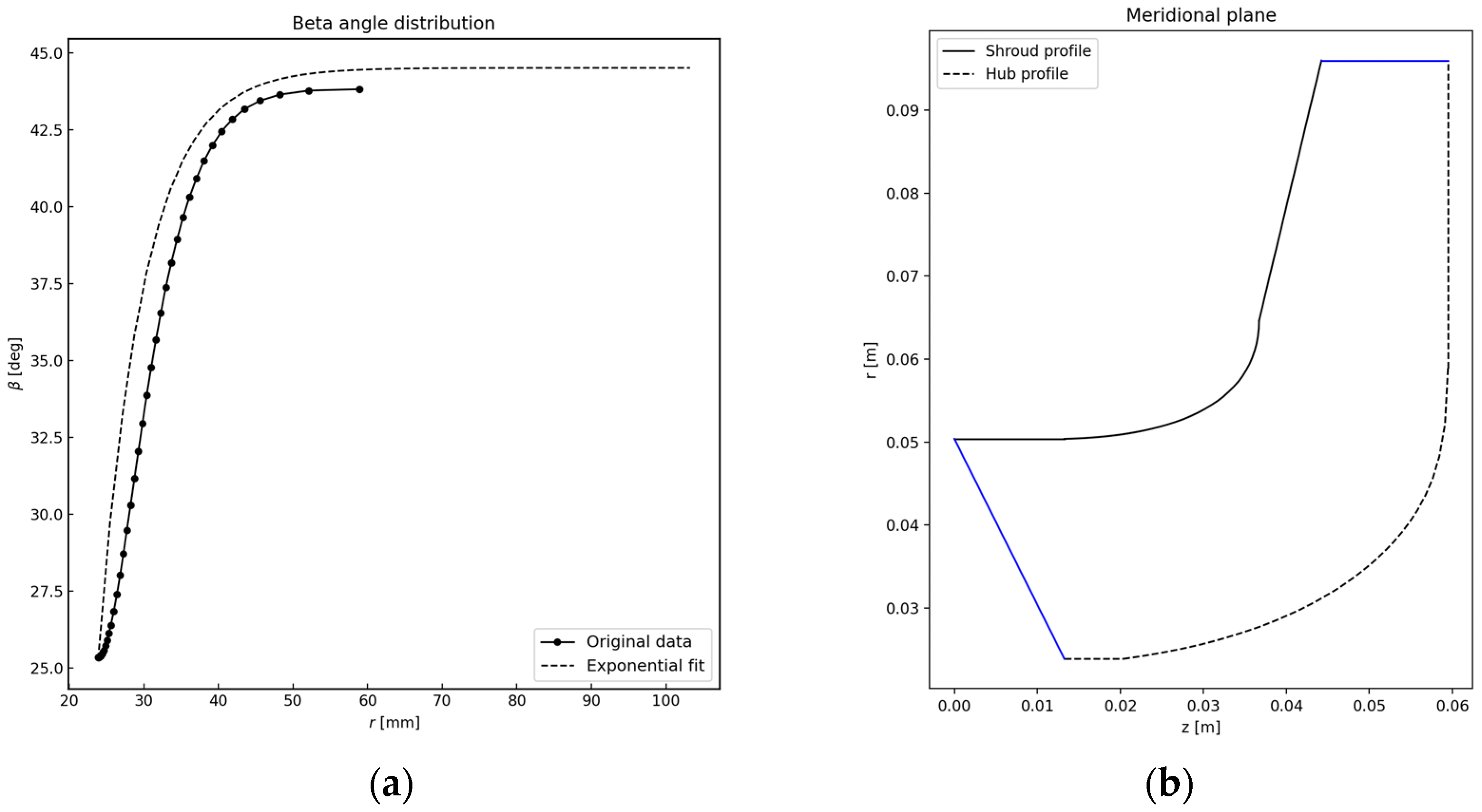
The equations used to calculate the blade angular distribution are summarized in Table 3. Figure 2a presents the distribution of the blade angle β along the impeller radius. The curve obtained through the exponential fitting adequately reproduces the trend of the distribution calculated from the summation in Equation (1). The good agreement between both curves indicates that the exponential function allows the blade angle variation to be described in a continuous and smooth manner, avoiding abrupt changes in the blade curvature.
Table 3.
Equations used for the calculation of the blade angular distribution.
Figure 2.
Geometric definition of the impeller: (a) blade angle distribution along the impeller radius and corresponding exponential fit; (b) meridional plane showing the shroud and hub profiles.
To determine the radial points of the blade, normalized coordinates are used, which allow each profile section to be located within the domain between the initial and final radii. The equations used to calculate the inner and outer meridional radius distributions are summarized in Table 4.
Table 4.
Equations for the meridional radius distribution of the impeller blade.
Where and are dimensionless radial coordinates proposed in [37], while ro, rgi, and rga correspond to the characteristic radii used to define the blade geometry. These normalized coordinates facilitate the ordered generation of the impeller meridional sections, as shown in Figure 2b.
2.3. Reverse Engineering
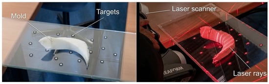
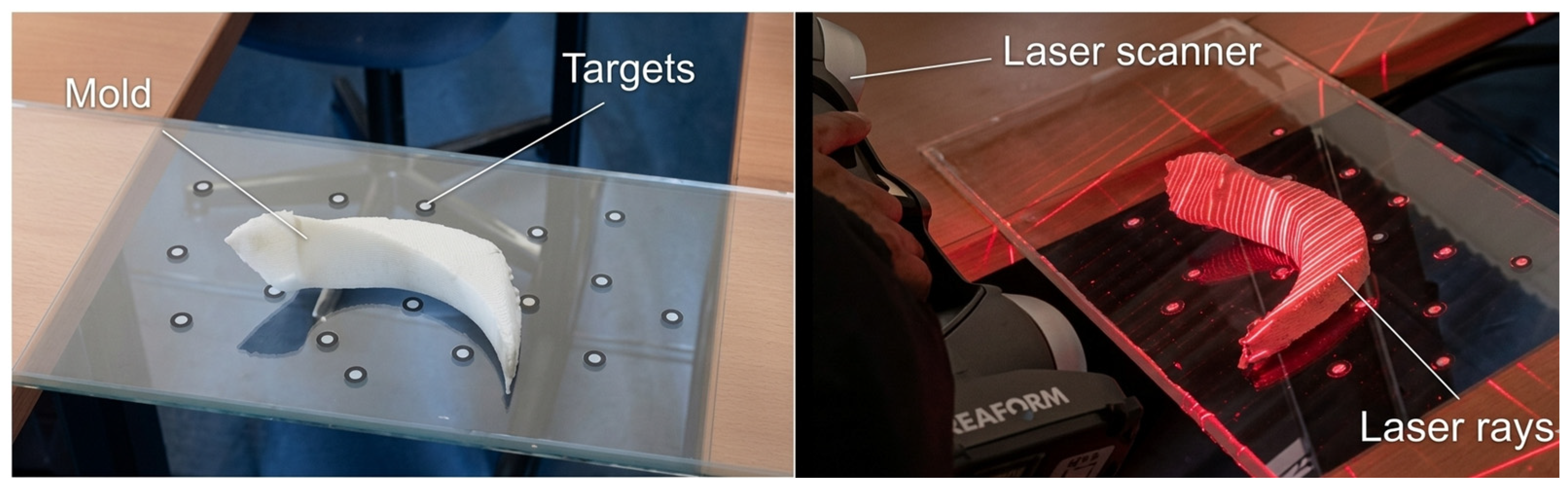
The geometry was digitized using a Creaform HandySCAN 3D 370 (Creaform Inc., Lévis, QC, Canada), a non-contact three-dimensional measurement system based on laser scanning technology. This device enables the generation of high-fidelity geometric models owing to its accuracy of up to 0.04 mm and volumetric accuracy of 0.02 mm + 0.04 mm/m. In addition, it provides a measurement resolution of 0.100 mm and a mesh resolution of 0.200 mm, making it suitable for capturing surfaces with high geometric complexity, such as those commonly found in hydraulic components.
During the data acquisition process, adhesive markers, commonly referred to as targets, were placed on the surface of the object and its surrounding area. These reference points allow the system to identify the relative position of the scanner in space and reconstruct the geometry with improved stability and precision (see Figure 3). The resulting point cloud can then be processed and exported in formats compatible with CAD platforms and computer-aided engineering tools, facilitating its subsequent use in modeling, analysis, and numerical simulation stages.
Figure 3.
3D scanning of the blade.
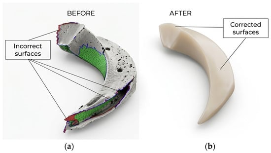
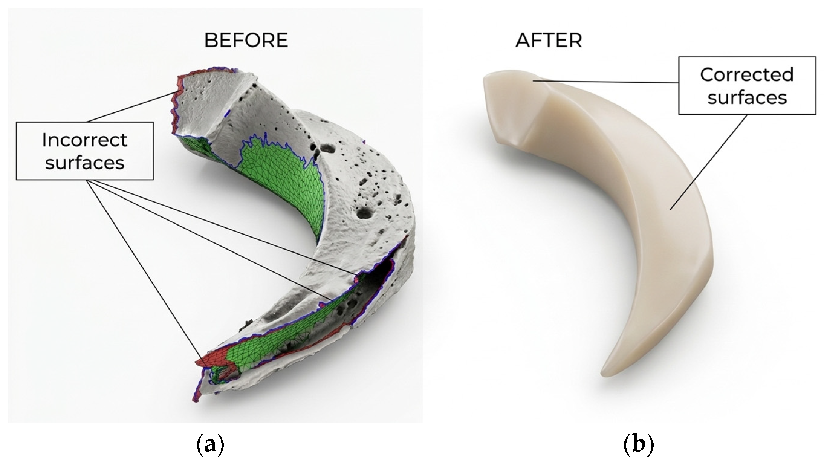
Figure 4 shows the geometric correction performed on the blade prior to the digitization and modeling process. In the initial condition, surface irregularities and geometric discontinuities were identified, which could affect the quality of the scanning process and, consequently, the fidelity of the resulting three-dimensional model. After refinement, a continuous and uniform surface was obtained, providing a more suitable representation of the actual component geometry and reducing potential errors in subsequent reconstruction and analysis stages.
Figure 4.
Blade geometry: (a) Before surface reconstruction and (b) after mesh refinement.
The information provided by the manufacturer made it possible to establish the reference operating conditions of the SAER NCB-65/200N-A centrifugal pump (see Table 5). These nominal data were used as the reference operating conditions for defining the initial and boundary conditions and for assessing the consistency of the CFD-predicted pump performance with the manufacturer-reported characteristic curve.
Table 5.
Manufacturer operating parameters of the SAER NCB 65-200NA pump.
2.4. CFD Model
The modeling of turbomachinery using computational fluid dynamics (CFD) methods allows the analysis of velocity and pressure fields within complex geometries such as the impeller and volute of a centrifugal pump [36,38,39,40]. The use of numerical simulations has become more frequent compared with experiments conducted using physical prototypes [41]. These tools help reduce research costs, as they allow potential problems to be identified or eliminated before the production or prototyping of the main components.
For the purposes of this study, numerical simulations were performed to compare the results obtained from the proposed methodology. These simulations were carried out using OpenFOAM version 12, which has been demonstrated in several studies to be an important open-source tool for obtaining reliable results [38,42,43,44].
In this study, the numerical simulations were carried out with the Multiple Reference Frame (MRF) model, which enables the rotating impeller region to be solved in a steady state manner, unlike the stationary parts such as the volute and the inlet and outlet parts. This approach is suitable for analysis of centrifugal pumps and pumps as turbines (PATs) as it provides a good compromise between the accuracy of the mean flow field and the computational efficiency, without the high cost of fully transient rotor-stator simulations. The angular velocity was applied to the impeller domain and its interaction with the stationary region was dealt with by a coupling interface.
2.4.1. Turbulence Model
In nearly all the studies using CFD tools, the k–ω SST turbulence model has been used [45,46,47]. This is an SST model that aggregates the benefits from two popular turbulence models, k–ω and k–ε. Due to this combination, it is possible to achieve pressure and velocity predictions closer to real flow conditions, both near the walls and in the main region of the computational domain [48]. This is essential when dealing with turbomachinery, especially in the regions around the impeller blades and along the volute walls.
where Pk represents the production of turbulent kinetic energy and μt is the turbulent viscosity, defined as:
where S is the invariant measure of the strain rate and F1 and F2 are blending functions used to combine the advantages of the k–ω formulation near the walls and the k–ε behavior in the free-stream region.
This hybrid formulation improves the prediction of flow separation and adverse pressure gradients, which are common in turbomachinery applications such as centrifugal pumps and (PAT) systems.
2.4.2. Mesh Generation
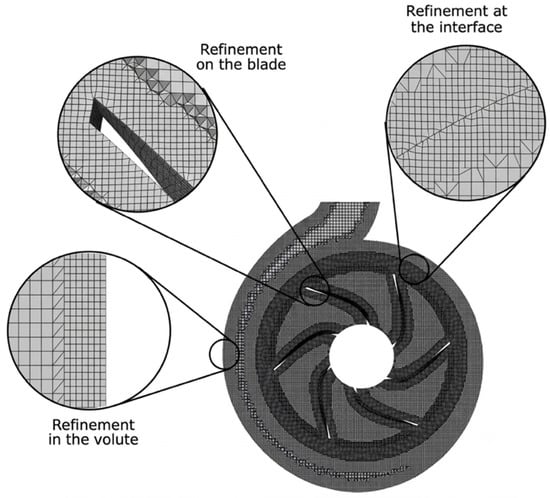
In CFD modeling, mesh generation can determine the success or failure of a numerical simulation, since mesh quality has a significant influence on the accuracy of the solution and on the computational cost required to solve the case study [45,49]. Different approaches have been developed to discretize the computational domain [50]. In this study, the mesh was generated using the native mesh generator snappyHexMesh, available in the OpenFOAM package. This tool enables the creation of a predominantly hexahedral mesh based on a background mesh previously generated with the blockMesh utility [51].
For the numerical analysis, the computational domains corresponding to the volute (Figure 5) and the impeller of the centrifugal pump were defined. To adequately capture the flow characteristics in each component, the mesh generation process was carried out independently for both domains. Figure 5 also shows that mesh refinement was concentrated in the regions near the volute and impeller walls, with the aim of improving the flow resolution in the boundary layer region.
Figure 5.
Computational domain.
2.4.3. Boundary and Initial Conditions
The studies [46,52] analyze three common combinations of boundary conditions used in centrifugal pump simulations:
- Total pressure at the inlet and mass flow rate at the outlet;
- Mass flow rate at the inlet and static pressure at the outlet;
- Total pressure at the inlet and static pressure at the outlet.
Although the third combination may offer higher accuracy, several studies indicate that the second combination is more numerically stable and converges faster, with only a minimal loss of accuracy [46].
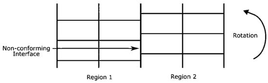
In OpenFOAM, two types of interfaces can be identified: implicit coupling interfaces and generalized mesh interfaces. The former are intended to connect conformal mesh regions, where the nodes of the patches on both sides of the interface match one-to-one (see Figure 6). The latter are used to couple non-conformal regions, where the patch nodes on each side of the interface do not coincide [53].
Figure 6.
Interface between two regions.
The modern approach for coupling non-conformal meshes between stationary and rotating regions in recent versions of OpenFOAM is known as NCC, or Non-Conformal Coupling [54]. This method replaces previous interface approaches, such as AMI and ACMI, which were commonly used in turbomachinery studies [47]. NCC provides a more robust strategy for coupling meshes that do not match node-to-node, while preserving the conservation of mass, momentum, and energy with improved numerical stability.
The initial conditions used to perform the simulation in turbine mode were calculated from the pump operating conditions, as reported in [47], for pumps with a specific speed within the range of 10 < ns < 70. The equations used to calculate these factors are summarized in Table 6.
Table 6.
Empirical correlations for estimating pump-as-turbine operating parameters [47].
In incompressible flow simulations performed in OpenFOAM, owing to this formulation, density does not appear explicitly in the pressure equation, and the pressure values imposed in the boundary conditions are interpreted in a relative sense. Therefore, only the pressure gradient is relevant, rather than the absolute pressure value [55]. However, to provide the results with physical reference, an outlet pressure condition of P = 101,325 Pa was selected. Table 7 summarizes the initial conditions for both pump and turbine operation.
Table 7.
Boundary and initial conditions for the simulation in Pump and turbine mode.
In both operating modes, the flow rate was defined as the inlet condition of the computational domain, while pressure was specified as the outlet condition. This configuration makes it possible to impose the flow entering the machine and to evaluate the hydraulic response of the system based on the reference pressure at the discharge.
2.5. Efficiency Formulation and Performance Metrics
The hydraulic performance of each impeller was evaluated based on the torque obtained from the numerical simulations. In pump mode, the efficiency was calculated as the ratio between the hydraulic power transferred to the fluid and the mechanical power supplied to the blades, as expressed in Equation (11). For turbine mode, the efficiency was determined as the ratio between the mechanical power extracted from the blades and the hydraulic power available in the flow, according to Equation (12).
In these expressions, the subscripts PUMP and PAT refer to the corresponding operating mode of the centrifugal machine. Therefore, (Q), (H), (ω), and (T) represent the volumetric flow rate, head, angular velocity, and torque, respectively, for each operating condition. In addition to the efficiencies obtained through the CFD simulations, the hydraulic efficiency in both operating modes was also estimated using the mathematical model. In the present study, hydraulic efficiency is considered the main parameter that varies between pump and turbine operation, since it allows the losses associated with the impeller to be incorporated for each operating mode.
The terms hT,PUMP and hT,PAT represent the hydraulic losses that occur when the machine operates in pump mode and turbine mode, respectively. These losses were calculated using the expressions proposed in [55]. Based on these relationships, the total efficiency for each operating mode was estimated by considering the mechanical efficiency, volumetric efficiency, and hydraulic efficiency, as indicated in Equations (13) and (14).
The product of the pump- and turbine-mode efficiencies, defined by Equation (17) and summarized in Table 8, should not be interpreted as a physical or thermodynamic efficiency associated with a single energy-conversion process. Instead, it is suggested as a dimensionless dual-mode performance index for comparison purposes. The index considers the hydraulic performance of the impeller in both directions of operation and penalizes geometries with low performance in either pump or turbine mode. Therefore, a higher value indicates a better compromise between the two operating conditions but does not indicate an additional energy-conversion efficiency of the centrifugal rotodynamic machine.
Table 8.
Equations used to evaluate hydraulic performance.
In addition to the CFD efficiencies, the hydraulic efficiency in both operating modes was estimated using the mathematical model. The terms hT,PUMP and hT,PAT represent the hydraulic losses occurring in pump and PAT operation, respectively, and were calculated using the expressions proposed in [55]. Based on these relationships, the total efficiency for each operating mode was estimated by considering the mechanical, volumetric, and hydraulic efficiencies, as indicated in Equations (13) and (14).
To complement the torque-based efficiency calculation, the energy-transfer mechanism was also interpreted using the velocity triangles and the angular-momentum equation. The hydraulic torque can be related to the change in angular momentum across the impeller as
where Cu1 and Cu2 are the tangential components of the absolute velocity at the corresponding impeller sections, and r1 and r2 are their characteristic radii. The velocity components were related through the classical velocity-triangle expression.
where C, U, and W denote the absolute, peripheral, and relative velocity vectors, respectively. These relationships were used to evaluate how variations in blade geometry modify the incidence condition in pump mode and the residual tangential velocity in PAT operation. The theoretical torque obtained from the angular-momentum relation was used only as a kinematic interpretation of the energy-transfer mechanism, whereas the efficiencies reported in Equations (11) and (12) were calculated using the torque obtained from the CFD simulations.
Tth = ρQ(r2Cu2 − r1Cu1),
C = U + W,
2.6. Monte Carlo-Based Parametric Sensitivity Analysis
A probabilistic sensitivity analysis was performed to quantify the influence of the main impeller geometric parameters on the hydraulic efficiency in both pump and turbine (PAT) operating modes. The analysis was based on Monte Carlo simulation and incorporated the same analytical hydraulic model used for the impeller design and loss estimation. Six geometric variables were considered: inlet blade angle β1, outlet blade angle β2, inlet width b1, outlet width b2, inlet diameter D1, and outlet diameter D2.
Each design variable was treated as an independent normally distributed random variable centered at its nominal design value,
where μi corresponds to the nominal geometric value and σi represents the prescribed standard deviation. For the blade angles, a standard deviation of 10° was adopted, whereas b1, b2, D1, and D2 were assigned standard deviations equal to 8% of their respective nominal values. These deviations were introduced as exploratory perturbations to evaluate the sensitivity of the analytical model and should therefore not be interpreted as experimentally determined manufacturing uncertainties.
A total of N = 50,000 random geometries were generated using a fixed random seed to ensure reproducibility. Before hydraulic evaluation, a geometric feasibility filter was applied to eliminate non-physical configurations. The blade angles were restricted to
while positive blade widths were imposed together with the geometric conditions
and
where D1H is the hub diameter. Each remaining sample was subsequently evaluated using the analytical loss model to determine the corresponding pump and PAT efficiencies. Samples producing undefined hydraulic quantities, negative theoretical heads, invalid friction correlations, or efficiencies outside the physically meaningful interval
were excluded from the statistical analysis.
5° < β1, β2 < 80°,
D1 > 1.05D1H,
D2 > 1.05D1,
0 < η < 1,
The sensitivity of each design parameter was first quantified using the Pearson correlation coefficient,
which provides a measure of the direction and strength of the linear relationship between each geometric variable and the predicted efficiency. The analysis was conducted independently for pump efficiency, ηPUMP, and turbine efficiency, ηPAT.
To enable a direct comparison among variables having different physical units and numerical ranges, standardized regression coefficients (SRCs) were also calculated. The input variables and efficiency responses were standardized according to
And
A multiple linear regression was then expressed as
where SRCi represents the standardized effect of the i-th geometric parameter and ε is the residual term. The sign of SRCi indicates whether increasing the parameter tends to increase or decrease the efficiency, whereas its absolute magnitude provides a comparative measure of sensitivity.
For a more intuitive comparison between the geometric variables, a normalized relative-importance index was additionally calculated from the absolute SRC values:
where Ii represents the percentage contribution of each parameter to the total standardized sensitivity. Separate importance rankings were obtained for pump and PAT operation, allowing the parameters governing each operating mode to be identified independently.
3. Results
3.1. Geometric Characterization of the Impeller Design
The final geometry of the analytically designed centrifugal impeller was obtained from the preliminary sizing procedure summarized in Table 2. The resulting geometric parameters are presented in Table 9. These dimensions represent the initial geometry generated by the analytical procedure and were subsequently evaluated through CFD without an intermediate geometric optimization stage.
Table 9.
Geometric parameters of the impeller obtained from the preliminary analytical sizing.
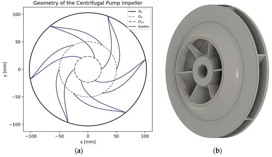
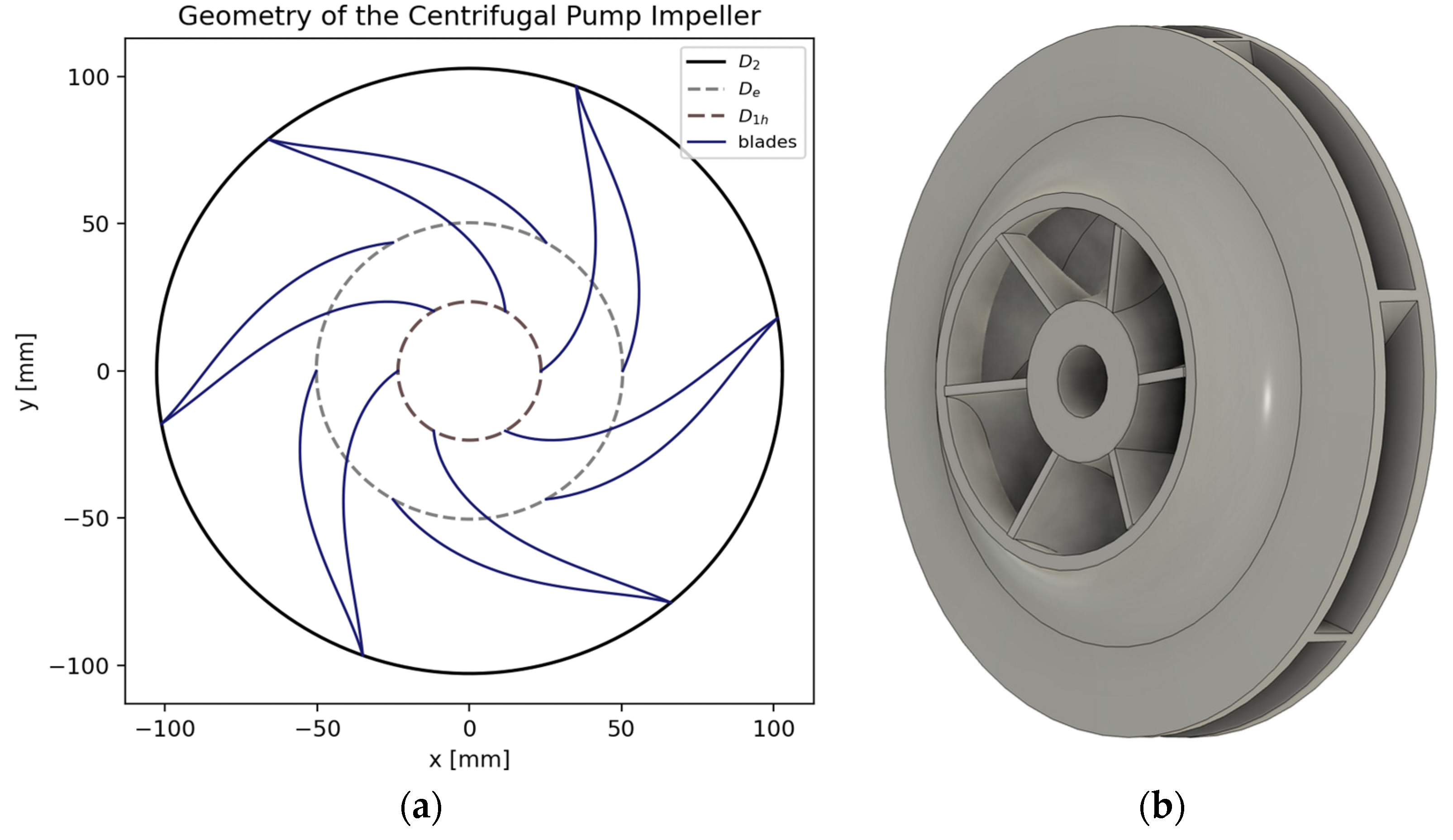
The geometry shown in Figure 7 is obtained from the main dimensional parameters and blade angles resulting from the analytical design stage. Figure 7a shows the impeller’s two-dimensional geometry, highlighting inlet and outlet diameters along with blade curvature, whereas Figure 7b illustrates the resultant three-dimensional representation. These parameters determine the final geometry of the impeller and were used as the geometric basis for the subsequent numerical simulations. The principal dimensions and hydraulic design variables are summarized in Table 9.
Figure 7.
Impeller geometry obtained from the preliminary analytical sizing procedure: (a) two-dimensional representation of the impeller geometry and blade profiles; (b) three-dimensional CAD model of the impeller.
3.2. Geometric Characterization of the Scanned Impeller
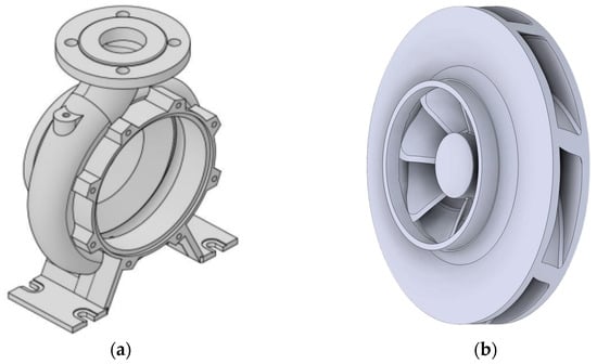
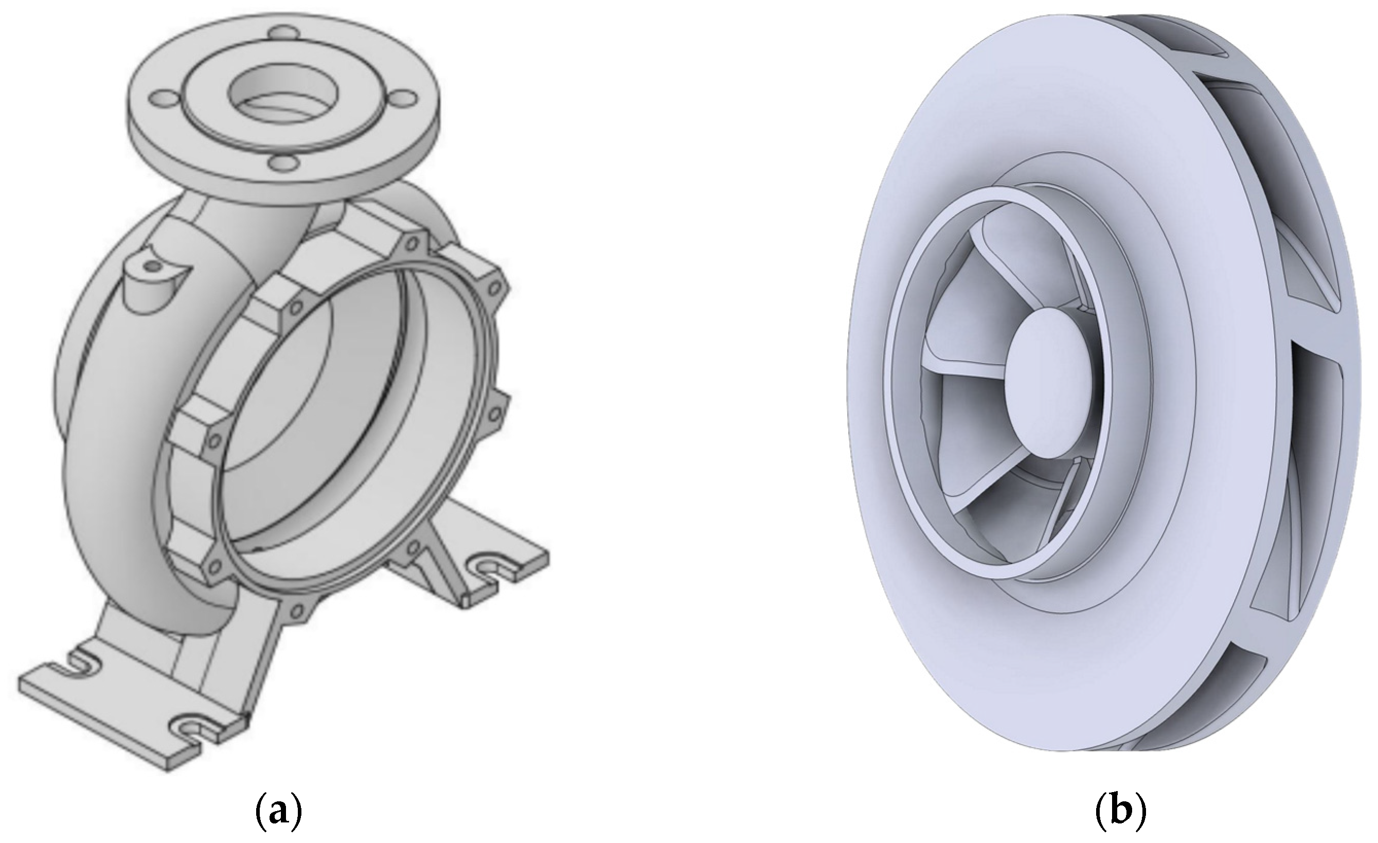
The scanned geometry shown in Figure 8 was used to extract the main dimensional and angular parameters of the original impeller. These values define the reverse-engineered configuration and allow a direct comparison with the analytically designed impeller presented previously.
Figure 8.
Geometries obtained after scanning the centrifugal pump: (a) volute and (b) impeller.
In this way, the inlet and outlet blade widths, eye diameter, hub diameter, shaft diameter, blade angles, and number of blades were identified from the reconstructed model. The corresponding parameters are summarized in Table 10.
Table 10.
Geometric parameters extracted from the reverse-engineered impeller.
3.3. Internal Flow Field Analysis in Pump Mode
Figure 9 shows the distribution of turbulent dissipation of the reverse engineered and designed impellers in pump mode. The reverse engineered impeller shows mostly low dissipation values in the impeller passages and in the volute. Local increases in the dissipation are observed near the blade trailing edges and in the region close to the volute tongue. At the same time, larger and stronger turbulent dissipation areas are found in the designed impeller, especially at the blade trailing edges and the impeller-volute interaction region. The high dissipation zones are bigger in the areas, and they get values near the upper part of the scale of the contour. The overall reverse-engineered geometry leads to a more uniform dissipation field. The designed impeller leads to stronger localized turbulent losses.
Figure 9.
Turbulent dissipation in pump mode: (a) reverse-engineered impeller and (b) designed impeller.
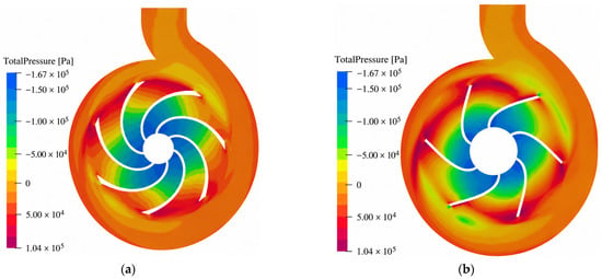
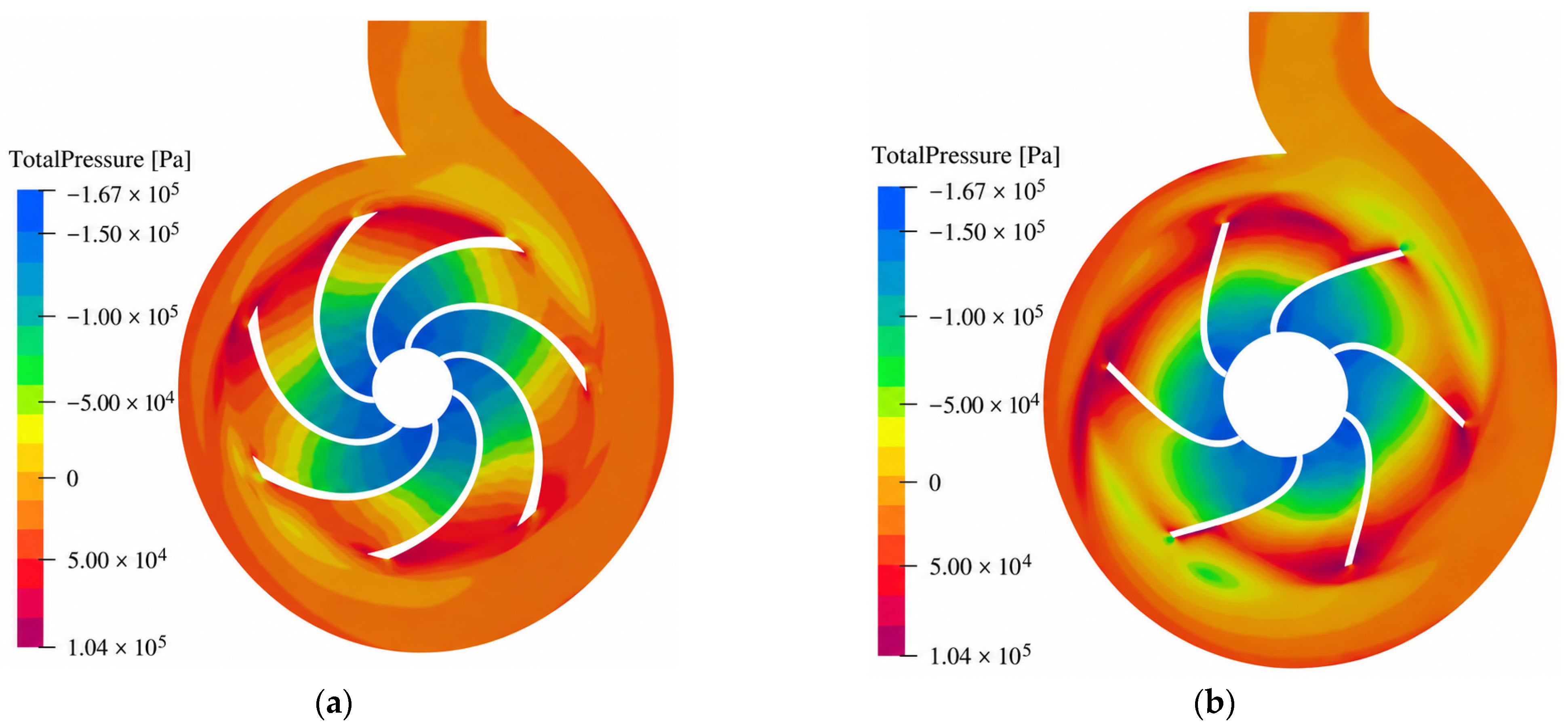
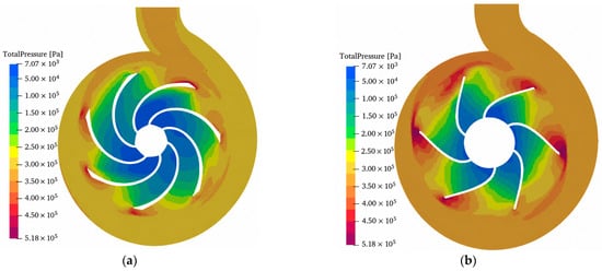
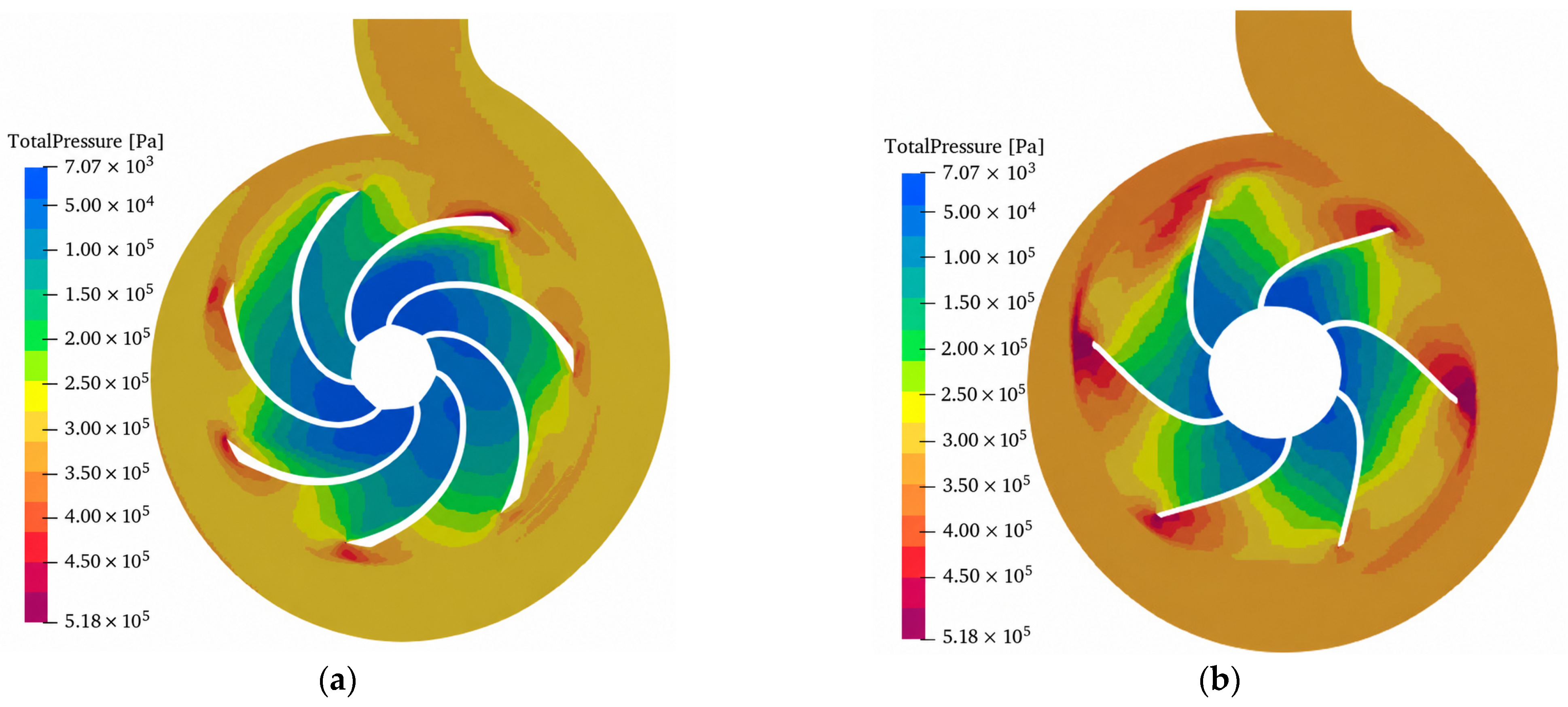
Figure 10 shows the comparison of the total-pressure distribution obtained in pump mode for the two impeller configurations. In both cases the total pressure shows a gradual increase from the inlet of the impeller to the outer part of the impeller and the volute. The reverse engineered impeller, however, has a relatively smoother distribution of pressure across the blade passages with smoother spatial variations. The designed impeller has more intensive pressure gradients and more extensive non-uniform total pressure regions especially near the blade outlet and the interface between the impeller and the volute. These differences suggest that the pressure field from the re-verse-engineered configuration is more uniform, while the designed geometry creates more pronounced local pressure variations in the flow domain.
Figure 10.
Total pressure of pump mode (a) reverse engineering impeller (b) design impeller.
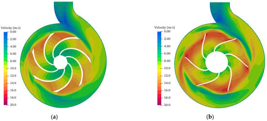
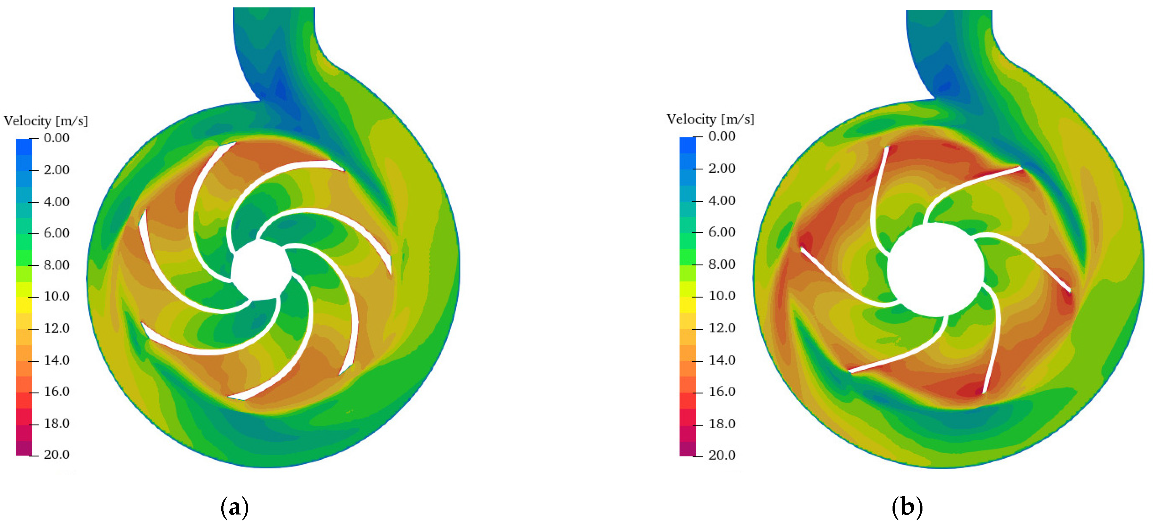
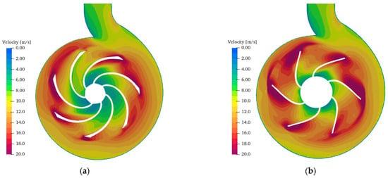
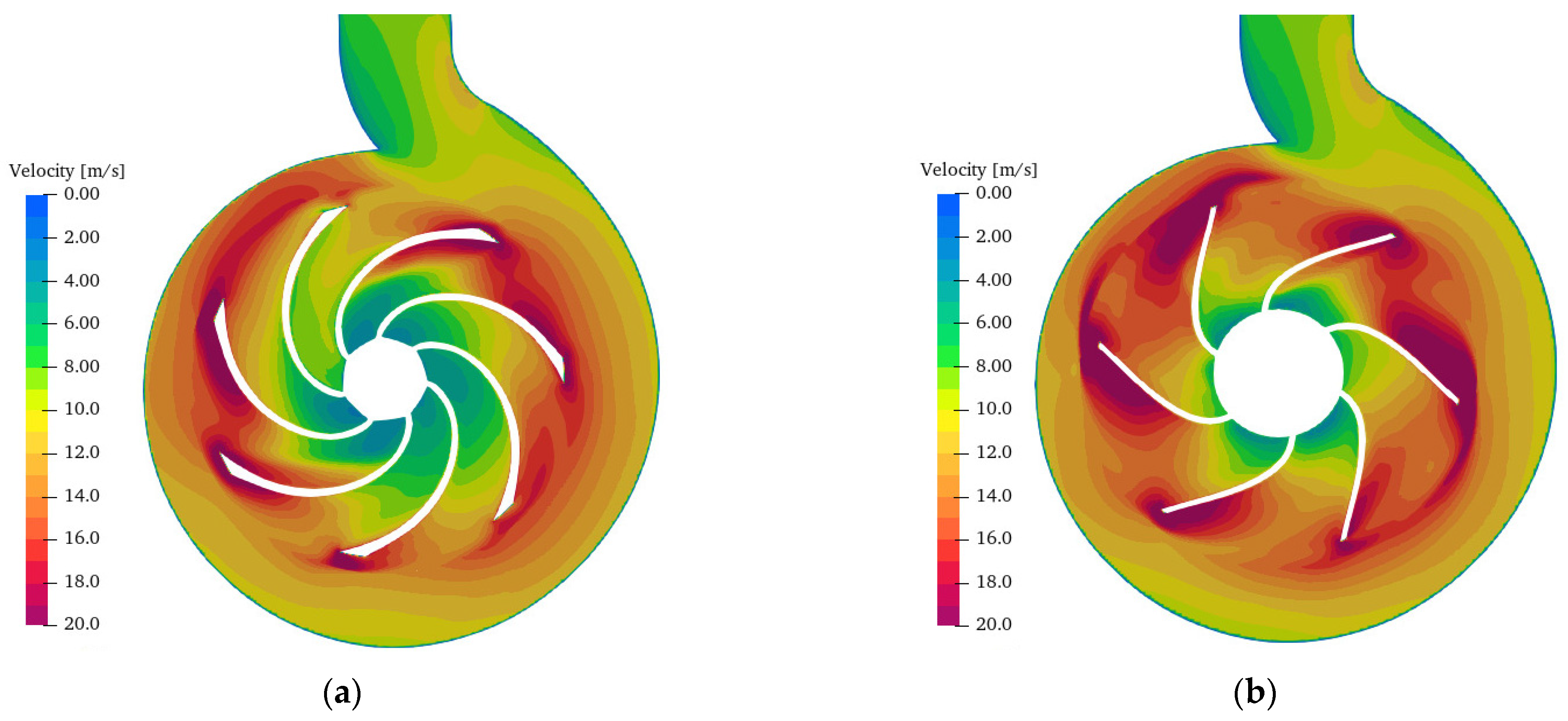
The velocity-magnitude contours of the two impeller configurations in the pump mode are shown in Figure 11. The flow velocity increases from the eye of the impeller to the outlet of the blade in both geometries. The reverse-engineered impeller has a uniform velocity distribution through the blade passages. The high velocity regions are more uniformly distributed around the circumference of the impeller. In contrast, the designed impeller has larger high velocity areas, especially around the blade outlet and larger tangential variations in the volute. The less uniform velocity field is characterized by the presence of low velocity regions between consecutive blade passages and near the volute. In both configurations, the maximum local velocities are in the order of 18–20 m/s, but the designed impeller has a larger area exposed to high velocities.
Figure 11.
Velocity of pump mode (a) reverse engineering impeller (b) design impeller.
3.4. Internal Flow Field Analysis in Turbine Mode
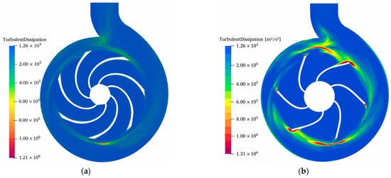
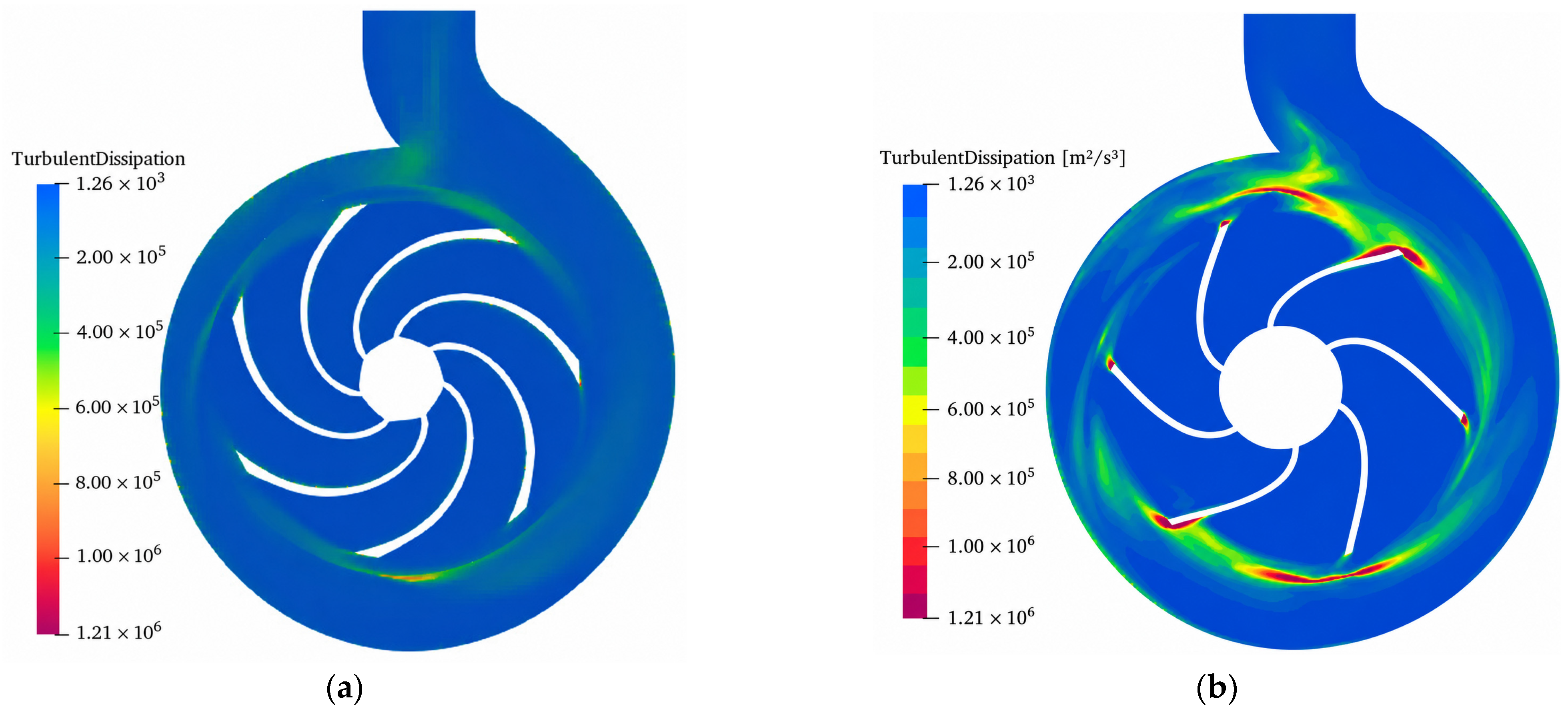
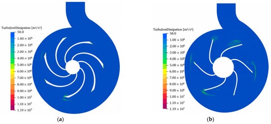
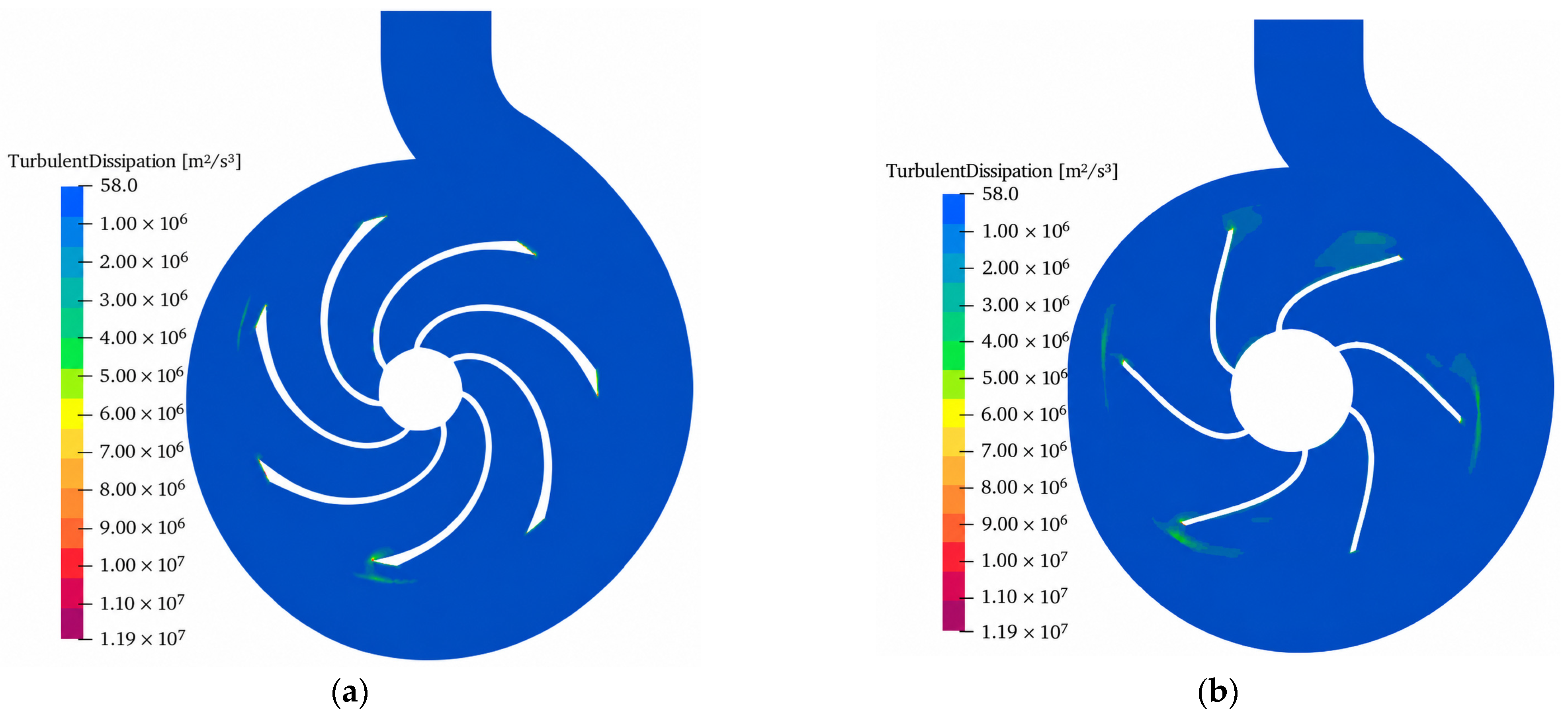
In turbine mode, the turbulent dissipation distribution for both impellers is shown in Figure 12. For both configurations low levels of dissipation are observed over most of the flow domain, while higher values are locally confined close to the blades and in the interaction region between the impeller passages and the volute. The reverse-engineered impeller is found to have relatively small and localized regions of increased turbulent dissipation, mainly near some blade edges. In contrast, the designed impeller has more spatially extended dissipation regions around several blade passages, especially in the peripheral region of the impeller. Therefore, the designed geometry exhibits a larger spatial extent of regions related to turbulent dissipation.
Figure 12.
Turbulent dissipation in turbine mode: (a) reverse-engineered impeller (b) designed impeller.
Figure 13 shows the total pressure distribution for both configurations in turbine mode. Since the flow direction is reversed in relation to a pump operation the fluid enters through the volute, passes into the impeller and moves radially toward the impeller eye. For both geometries the total pressure decreases gradually from the periphery to the center of the impeller, which corresponds to the hydraulic energy transfer to the rotating impeller during the turbine operation. The inverse-engineered impeller has a relatively slow pressure change through the blade passages. Conversely, the designed impeller exhibits larger local pressure gradients, in the outer blade areas, where localized areas with high total pressure can be observed. The differences point to the greater circumferential non-uniformity of the pressure field for the designed impeller.
Figure 13.
Total pressure of turbine mode: (a) reverse-engineered impeller and (b) design impeller.
The distribution of the velocity magnitude for both configurations in turbine mode is presented in Figure 14. In both cases, the velocity reaches maximum values in the peripheral region of the impeller and near the blades. When the flow is directed to the impeller eye, the velocity decreases gradually. The reverse engineered impeller also displays a rather continuous velocity distribution between the different blade passages, but some localized high-velocity zones can be observed near the blades. In contrast, the designed impeller presents larger areas of high velocity, locally reaching about 18–20 m/s. Also, there are bigger variations in circumferential velocity between consecutive passages which suggests less uniform distribution of flow inside.
Figure 14.
Velocity of turbine mode: (a) reverse-engineered impeller and (b) design impeller.
3.5. Convergence
To ensure the reliability of the numerical results, a mesh independence study was conducted considering five refinement levels, as shown in Table 11. The evaluation criterion adopted was the torque obtained in each case, since this variable directly represents the energy exchange between the fluid and the impeller. It can be observed that, as the number of elements increases from 915,175 to 1,143,668, the torque value shows practically no significant variation, while from 1,923,952 elements onward, the result converges to a constant value of 22.00 N·m. This behavior indicates that, from Case 3 onward, the solution can be considered mesh-independent, since further refinements do not produce appreciable changes in the variable of interest.
Table 11.
Mesh independence.
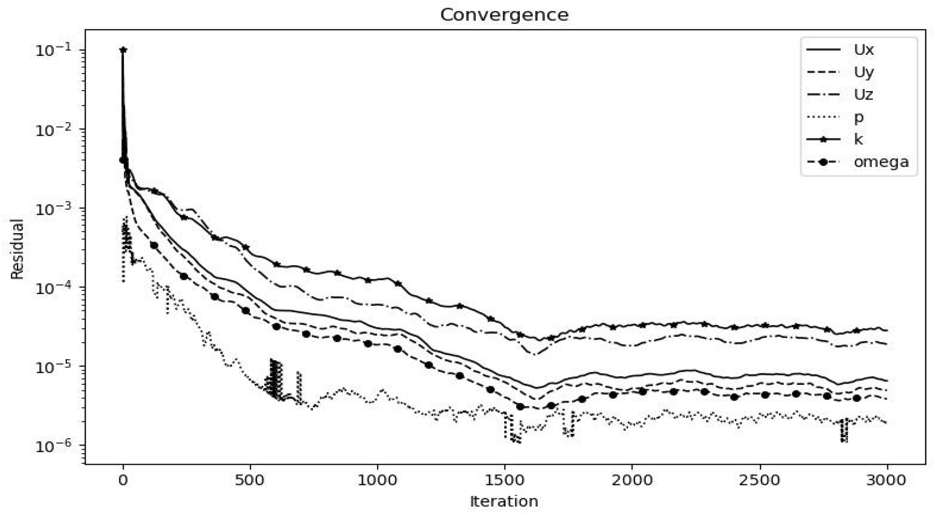
In addition, Figure 15 presents the evolution of the residuals of the governing equations during the iterative process. A sustained decrease in the residuals of velocity, pressure, and turbulent variables is observed, reaching levels on the order of 10−5 and 10−6, which indicates adequate numerical stability of the solution. Although some variables show slight oscillations at the end of the simulation, they remain bounded and do not affect the overall convergence of the case. Overall, both the mesh independence study and the residual behavior confirm that the selected mesh and the numerical configuration employed are appropriate for the hydraulic analysis carried out.
Figure 15.
Residuals.
The dimensionless wall distance, y+, was also used to evaluate the near-wall resolution of the selected mesh. In the present simulation an average y+ value of around 60 was obtained. This value is considered acceptable with the chosen turbulence treatment, being in the usual range of 30 to 300 used with wall functions. Hence, the first cell is in the logarithmic region of the boundary layer where the wall-function approach can properly capture the near-wall velocity gradients.
3.6. Efficiency
From Table 12, the reverse-engineered impeller has the best performance in both modes of operation. The turbine mode shows that the efficiency of this impeller is 67%, which is 17 percentage points higher than the efficiency obtained with the designed impeller. The trend is similar in pump mode with the reverse engineered impeller reaching 90.50% and the designed impeller reaching 79.17%. This difference of 11 percentage points shows that the commercial geometry exhibits a more favorable hydraulic behavior for the evaluated conditions, particularly when the machine is used as a turbine.
Table 12.
Comparison of CFD efficiencies for the reverse-engineered and analytically designed impellers.
For the analytically designed impeller, the analytical model predicts efficiencies of 76% in pump mode and 51% in PAT mode, whereas the corresponding CFD values are 79.17% and 50%, respectively. The differences are therefore approximately 3 and 1 percentage points for pump and PAT operation, respectively. This numerical proximity is reported only as a consistency assessment between the preliminary analytical sizing procedure and the CFD results and should not be interpreted as validation of the analytical model.
3.7. Pump-Mode Performance Consistency Assessment
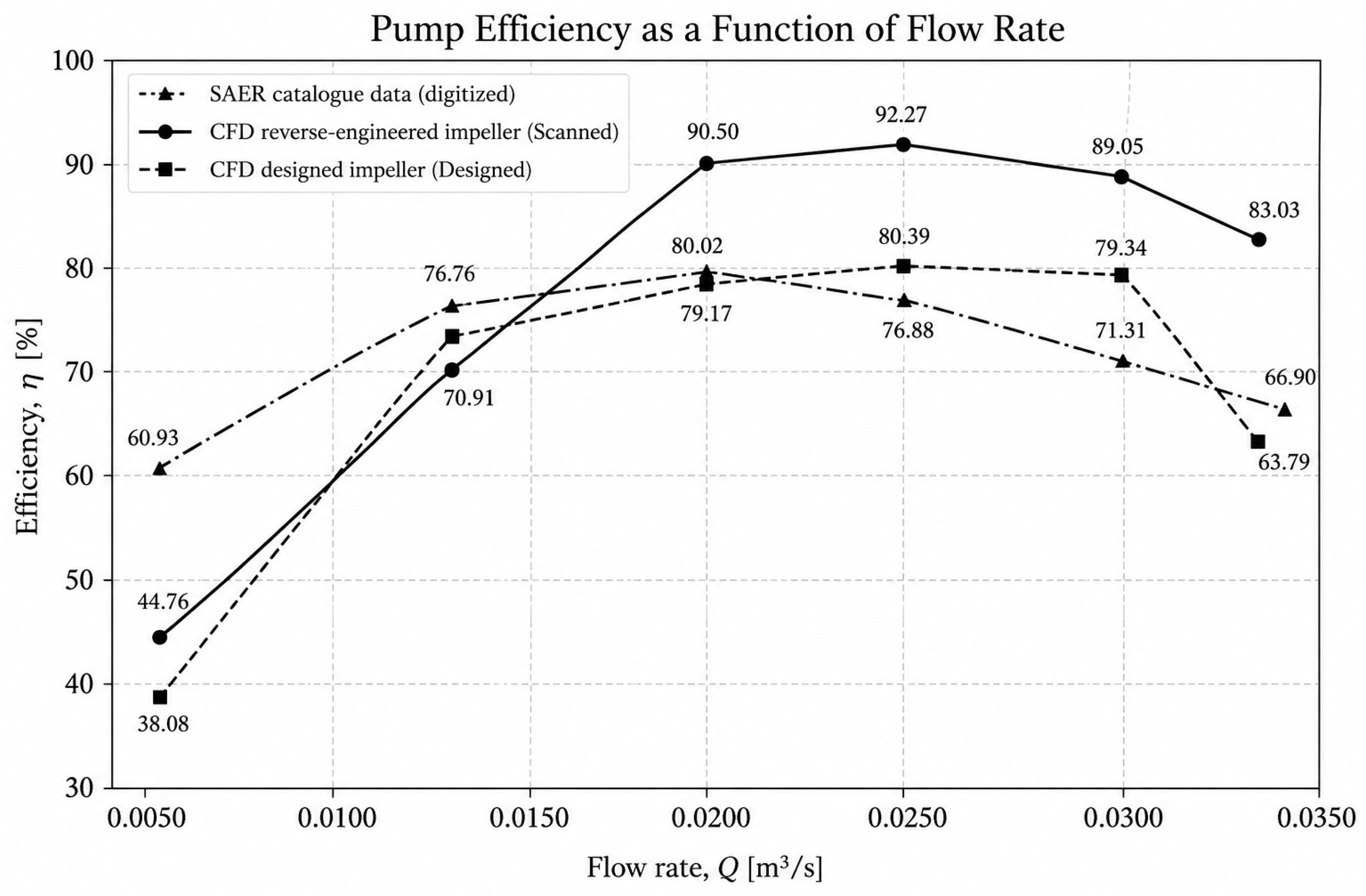
To evaluate the capability of the numerical model to reproduce the pump performance, the CFD predicted efficiencies were compared with the characteristic curve provided by the manufacturer for the SAER NCB 65-200NA pump (SAER Elettropompe S.p.A., Guastalla, Reggio Emilia, Italy). The manufacturer data were digitized at various flow rates and compared to results for both the reverse-engineered and designed impellers. All simulations were performed at a constant rotational speed of 1800 rpm, which allowed the overall trend of the efficiency curves as well as the location and magnitude of the best efficiency point to be evaluated.
Figure 16 shows that all three cases initially exhibit an increase in efficiency with increasing flow rate, followed by a decrease after reaching the maximum-efficiency region. The manufacturer data indicate a maximum efficiency of approximately 80.02% at Q = 0.020 m3/s. At the same flow rate, the designed impeller achieves an efficiency of 79.17%, corresponding to a difference of only 0.85 percentage points relative to the catalogue value. Its maximum efficiency subsequently reaches 80.39% at Q = 0.025 m3/s, indicating a slight shift of the best-efficiency point toward a higher flow rate.
Figure 16.
Comparison of pump efficiency as a function of flow rate for the SAER NCB 65-200NA manufacturer data, the reverse-engineered impeller, and the designed impeller at 1800 rpm.
In contrast, the reverse-engineered impeller reaches an efficiency of 90.50% at Q = 0.020 m3/s and a maximum value of 92.27% at Q = 0.025 m3/s. Therefore, although the general trend of increasing and subsequently decreasing efficiency is reproduced, this configuration substantially overpredicts the manufacturer efficiency in the region near and above the design flow rate. For instance, at Q = 0.025 m3/s, the difference with respect to the catalogue curve is approximately 15.39 percentage points.
Differences between the numerically calculated efficiency and the overall pump efficiency reported by the manufacturer may partially cause the observed discrepancies. The CFD model mainly considers the hydraulic losses in the simulated flow domain, but the efficiency of the real pump may also include leakage, clearance, disk-friction, sealing, bearing and other mechanical losses, which are not necessarily modeled in the numerical model. But the designed impeller better estimates the magnitude of manufacturer efficiency near the nominal operating condition although its estimated best efficiency point is shifted toward a higher flow rate.
The comparison with the manufacturer performance curve should not be interpreted as a validation of the CFD model. Rather, it provides a performance-consistency assessment under the adopted numerical assumptions. At the design flow rate, the CFD efficiency of the analytically designed impeller (79.17%) is close to the manufacturer-reported efficiency (80.02%), whereas the reverse-engineered impeller yields a substantially higher CFD efficiency (90.50%). This discrepancy indicates that the hydraulic efficiency obtained from the simulated domain cannot be directly equated with the overall pump efficiency reported by the manufacturer. Loss mechanisms not explicitly represented in the numerical model, including leakage, mechanical losses, clearances, surface roughness, and other installation-related effects, may contribute to the observed overprediction. Therefore, the manufacturer data are used primarily as a reference for assessing the consistency and limitations of the numerical results rather than as an experimental validation of the CFD model.
3.8. Effect of the Blade Inlet Angle Under Pump and PAT Operation
The comparison focuses on the designed impeller with β1 = 18.26° and the reverse-engineered impeller with β1 = 59°. The main results are summarized in Table 13.
Table 13.
Velocity-triangle parameters associated with the blade inlet angle under pump and PAT operation.
In pump operation, the designed impeller presents an incidence angle close to zero (−1.85°), indicating a relatively well-aligned inlet velocity triangle. In contrast, the 59° blade angle produces a considerably larger incidence of approximately 40.5°, indicating a greater potential for leading-edge impact and incidence-related losses.
In PAT operation, the hydraulic role of the same blade section changes because it becomes the impeller outlet. The 59°configuration reduces the calculated residual tangential velocity from 18.54 to 10.34 m/s, corresponding to a reduction of approximately 44.2%. Under the ideal velocity-triangle approximation, this reduction increases the angular-momentum change across the impeller and results in an estimated increase of approximately 20% in the torque-transfer potential. These results confirm that the effect of β1 is strongly dependent on the direction of operation.
3.9. Parametric Sensitivity Analysis
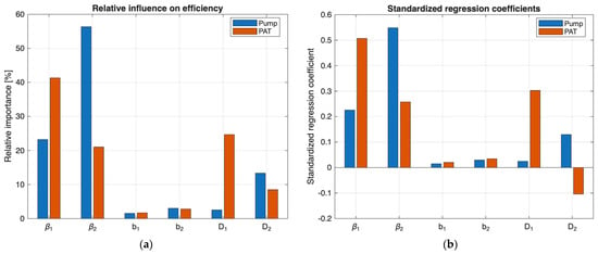
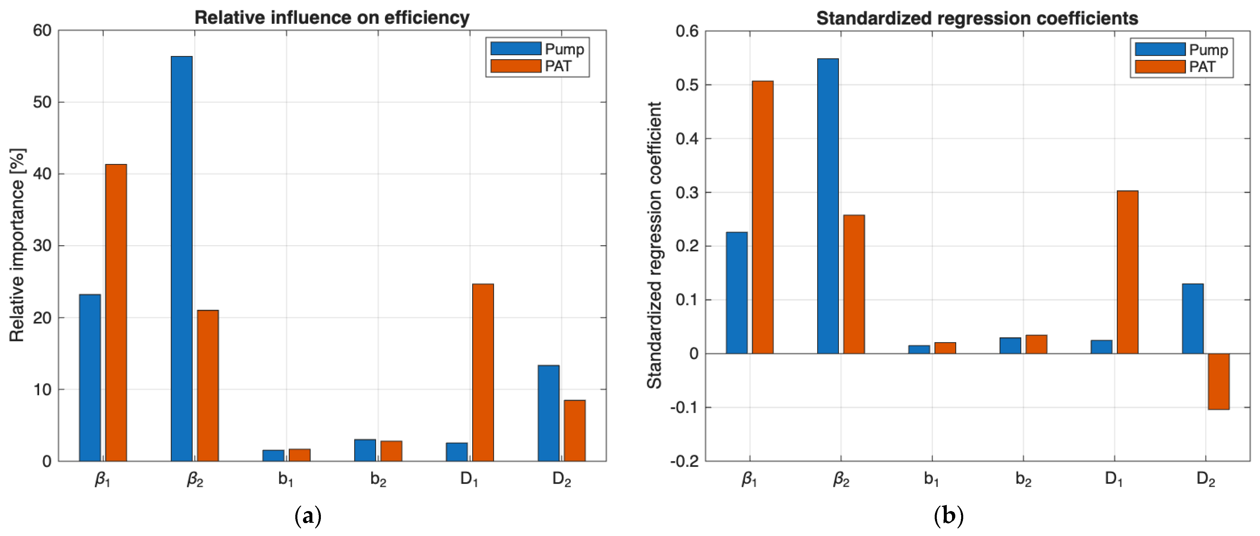
Figure 17 shows that the influence of the impeller geometric parameters changes significantly between pump and PAT operation. In pump mode, the outlet blade angle β2 is the dominant variable, accounting for approximately 56% of the normalized sensitivity, followed by the inlet blade angle β1 with about 23% and the outlet diameter D2 with approximately 13%. The blade widths b1 and b2, together with D1, show comparatively low influence.
Figure 17.
Sensitivity of impeller geometric parameters on pump and PAT efficiencies: (a) normalized relative influence and (b) standardized regression coefficients (SRC).
In PAT mode, the sensitivity ranking changes. The inlet blade angle β1 becomes the most influential parameter, with approximately 41% of the normalized sensitivity, followed by the inlet diameter D1 with about 25% and β2 with approximately 21%. The remaining parameters present lower contributions.
The standardized regression coefficients shown in Figure 17b confirms these trends. In pump mode, β2 presents the largest positive coefficient, while in PAT mode β1 becomes dominant and D1 also shows a strong positive effect. In addition, D2 changes from a positive influence in pump operation to a negative influence in PAT mode, indicating an opposite response of this parameter depending on the direction of operation. Overall, the results demonstrate that the geometric variables governing hydraulic performance are mode dependent.
4. Discussion
The numerical results confirm that the impeller geometry strongly influences the hydraulic response of the machine under reversible operation. Although both impellers have the same outer diameter (D2 = 205 mm) and similar eye diameters, important differences exist in blade widths, blade angles, and blade number. The reverse-engineered impeller has b1 = 37 mm, b2 = 18 mm, seven blades, β1 = 59°, and β2 = 27.5°, whereas the designed impeller has b1 = 30 mm, b2 = 15 mm, six blades, β1 = 18.29°, and β2 = 34.23°. These differences modify the available flow passages, blade guidance, and velocity distribution; therefore, the observed performance cannot be attributed to a single geometric parameter.
In pump mode, the reverse-engineered impeller exhibits a more uniform internal flow distribution, with high turbulent-dissipation regions mainly localized near the blade trailing edges and the impeller–volute interaction region. In contrast, the designed impeller presents broader regions of elevated velocity and turbulent dissipation near the outlet. The narrower blade passages of the designed geometry, together with its different blade angles and lower blade count, contribute to stronger local velocity and total-pressure gradients. Since the simulations were performed under steady-state conditions, these variations represent persistent spatial non-uniformities rather than temporal fluctuations.
The inferior performance of the analytically designed impeller should not be interpreted as evidence that the underlying design equations are intrinsically unsuitable for impeller sizing. Rather, the observed performance may result from the combined effects of the assumptions and limitations associated with the adopted analytical and semi-empirical design equations, the parameter choices made during preliminary sizing, and the geometric characteristics of the resulting impeller. Compared with the reverse-engineered geometry, the analytically designed impeller has narrower inlet and outlet passages and a lower blade number, which may contribute to higher local velocities, stronger pressure gradients, and increased hydraulic losses. Therefore, the lower efficiency cannot be attributed to a single design parameter or equation. Instead, it reflects the combined hydraulic response of the resulting geometry, reinforcing the role of the analytical procedure as a preliminary sizing approach whose output requires subsequent CFD-based assessment and refinement.
The differences become more pronounced in PAT operation because the hydraulic role of the blade sections is reversed. The pump outlet becomes the runner inlet, while the pump inlet becomes the runner outlet toward the eye. Under this condition, the designed impeller develops more extensive high-velocity and high-dissipation regions and greater circumferential pressure non-uniformity. Conversely, the reverse-engineered impeller maintains a smoother pressure distribution and more localized dissipation, indicating a better adaptation of its complete geometry to reversed flow.
These flow characteristics are consistent with the efficiency results. The reverse-engineered impeller reaches 90.50% in pump mode and 67% in PAT mode, compared with 79.17% and 50%, respectively, for the designed impeller. The larger difference observed in PAT operation indicates that reversible performance is particularly sensitive to the interaction between blade angles and passage dimensions. Consequently, satisfactory pump performance does not necessarily guarantee favorable turbine operation.
The velocity-triangle analysis further clarifies the role of β1. In pump mode, the designed impeller presents a relative-flow direction close to its blade angle of 18.26°, whereas the 59° angle of the reverse-engineered impeller produces a larger incidence mismatch. Therefore, the 59° angle should not be considered intrinsically advantageous in pump operation. Its higher pump efficiency must instead result from the combined effect of the complete geometry, including blade widths, blade number, and the remaining blade-angle distribution.
In PAT operation, however, the hydraulic function of β1 changes because this section becomes the runner outlet. The velocity-triangle analysis shows that the residual tangential velocity decreases from 18.54 m/s for the designed impeller to 10.34 m/s for the reverse-engineered configuration, representing a reduction of approximately 44.2%. This lower residual swirl favors a greater change in angular momentum and therefore torque extraction. Thus, the same blade section that produces an unfavorable incidence condition in pump mode can contribute to a more favorable discharge condition in PAT operation. Nevertheless, this behavior must still be interpreted together with the differences in passage width and blade geometry.
The sensitivity analysis in Figure 17 supports this interpretation. In pump mode, β2 is the dominant parameter, with approximately 56% of the normalized sensitivity, followed by b2 at about 23% and D2 at approximately 13%. In PAT operation, the influence shifts toward the opposite blade section, with β1 contributing approximately 41% and b1 about 25%. This change confirms that the geometric parameters controlling performance depend strongly on the direction of operation. The standardized regression coefficients also show that a parameter can have different, or even opposite, effects in pump and PAT modes, highlighting the inherent trade-off in reversible impeller design.
The analytical model provided a preliminary estimate for the designed impeller, predicting efficiencies of 76% in pump mode and 51% in PAT mode, compared with CFD values of 79.17% and 50%, respectively. The analytical procedure combines analytical and semi-empirical design equations adopted from different centrifugal-pump design references and is intended for preliminary sizing rather than performance optimization. Since a common calibration domain is not defined for these equations and explicit applicability ranges are not reported for several of them in the original sources, the numerical proximity between the analytical and CFD results should be interpreted cautiously. Therefore, this comparison is considered a consistency assessment of the preliminary sizing procedure rather than an independent validation of the analytical model.
Overall, the combined CFD, velocity-triangle, and sensitivity analyses indicate that the higher performance observed of the reverse-engineered impeller results from the interaction of several geometric characteristics rather than from the 59° blade angle alone. Pump performance is mainly governed by outlet geometry, particularly β2 and b2, whereas PAT performance becomes more sensitive to β1 and b1. These results indicate that impellers intended for reversible operation should be designed by considering the hydraulic requirements of both operating directions simultaneously rather than relying exclusively on conventional pump-design criteria.
5. Conclusions
The results indicate that impeller geometry strongly influences the hydraulic performance of the centrifugal machine in both pump and PAT operation. Although the two impellers have the same outer diameter, differences in blade angles, passage widths, and number of blades lead to noticeably different internal flow fields. The reverse-engineered impeller generally exhibits more uniform velocity and total-pressure distributions and less extensive regions of turbulent dissipation, particularly under reversed operation.
These differences are reflected in the hydraulic performance. The reverse-engineered impeller achieved efficiencies of 90.50% in pump mode and 67% in PAT mode, whereas the analytically designed impeller reached 79.17% and 50%, respectively. For the geometries and operating conditions investigated, the larger performance difference observed in PAT operation indicates that satisfactory pump performance does not necessarily imply equally favorable behavior when the flow direction is reversed.
The velocity-triangle analysis clarified the mode-dependent role of the inlet blade angle. In pump mode, the designed impeller with β1 = 18.26° exhibited an incidence angle of only −1.85°, whereas the reverse-engineered impeller with β1 = 59° produced an incidence of approximately 40.46°. Therefore, the 59° angle should not be considered intrinsically advantageous for pump operation. In PAT mode, however, the same blade section becomes the impeller outlet, and the reverse-engineered configuration reduces the calculated residual tangential velocity by approximately 44.2%, favoring angular-momentum transfer and torque extraction.
The parametric sensitivity analysis further indicated that the dominant geometric parameters depend on the operating direction. In pump mode, β2 was the most influential variable, accounting for approximately 56% of the normalized sensitivity, followed by β1 with about 23% and D2 with approximately 13%. In PAT mode, β1 became the dominant parameter, with approximately 41% relative influence, followed by D1 at about 25% and β2 at approximately 21%. In addition, D2 exhibited opposite sensitivity trends between pump and PAT operation, highlighting the geometric trade-off inherent to reversible impeller design.
The analytical model predicted efficiencies of 76% and 51% in pump and PAT modes, compared with CFD values of 79.17% and 50%, respectively. However, because the analytical procedure combines analytical and semi-empirical design equations from different reference formulations and is intended for preliminary sizing, this numerical agreement should be interpreted cautiously. Therefore, the observed numerical proximity is considered a consistency assessment rather than validation of the analytical procedure.
The mesh-independence and convergence analyses supported the numerical reliability of the simulations, with the calculated torque remaining essentially unchanged from approximately 1.92 million elements onward and an average y+ of approximately 60, consistent with the adopted wall-function treatment.
Overall, within the operating conditions and modeling assumptions considered in this study, the results indicate that the geometric parameters governing pump performance are not necessarily those controlling PAT operation. The analytical procedure should therefore be regarded as a preliminary sizing tool rather than a validated dual-mode optimization method. The lower performance of the analytically designed impeller may result from the combined effects of the adopted analytical and semi-empirical design equations, the selected design parameters, and the resulting geometric characteristics, including narrower flow passages and a lower blade number. Consequently, impellers intended for reversible operation require subsequent CFD-based assessment and refinement considering both operating directions. Future work should combine experimental validation with multi-objective optimization to improve the hydraulic compromise between pumping and energy-recovery operation.
Author Contributions
Conceptualization, S.A., J.E. and V.H.; methodology, S.A. and J.E.; software, S.A. and M.N.; validation, S.A. and J.E. formal analysis, S.A. and J.E.; investigation, S.A.; resources, V.H., Data curation, M.N. and G.B., writing—original draft preparation, S.A. and G.B.; writing—review and editing, S.A., M.N. and H.C.; visualization, S.A. and G.B.; supervision, V.H.; funding acquisition, J.E. All authors have read and agreed to the published version of the manuscript.
Funding
This research received no external funding.
Institutional Review Board Statement
Not applicable.
Informed Consent Statement
Not applicable.
Data Availability Statement
All data generated or analyzed during this study are included in this published article.
Acknowledgments
The authors gratefully acknowledge the Universidad de las Fuerzas Armadas ESPE and the Escuela Politécnica Nacional (EPN) for their academic and institutional support throughout the development of this research.
Conflicts of Interest
The authors declare no conflicts of interest.
References
- Sun, X.; Huang, H.; Zhao, Y.; Tong, L.; Lin, H.; Zhang, Y. A Review of Methods for ‘Pump as Turbine’ (PAT) Performance Prediction and Optimal Design. Fluid Dyn. Mater. Process. 2025, 21, 1261–1298. [Google Scholar] [CrossRef] [Scilit]
- Mao, X.; Hu, J.; Pan, Z.; Zhong, P.; Zhang, N. A Brief Review of Recent Research on Reversible Francis Pump Turbines in Pumped Storage Plants. Energies 2025, 18, 394. [Google Scholar] [CrossRef] [Scilit]
- Da Silva Corrêa, S.; De Souza, J.D.S.; De Oliveira, A.A.A.; Bezerra, S.d.T.M. Pumps as turbines for energy recovery in water distribution systems: A review. Proc. Inst. Civ. Eng.-Energy 2023, 177, 74–84. [Google Scholar] [CrossRef] [Scilit]
- Souček, J.; Bílková, E.; Nowak, P. Reverse engineering of pump as turbine for CFD analysis. Acta Polytech. 2024, 64, 52–58. [Google Scholar] [CrossRef] [Scilit]
- Abdulshaheed, A.; Mustapha, F.; Dol, S.S.; Ahmad, K.A.; Mustapha, M.; Anuar, M. Reverse engineering of impellers to reduce pipe network pressure and enable sustainable power generation using pumps as turbines (PATs). Results Eng. 2025, 28, 108124. [Google Scholar] [CrossRef] [Scilit]
- Nasir, A.; Dribssa, E.; Girma, M.; Madessa, H.B. Selection and Performance Prediction of a Pump as a Turbine for Power Generation Applications. Energies 2023, 16, 5036. [Google Scholar] [CrossRef] [Scilit]
- Derakhshan, S.; Nourbakhsh, A. Experimental study of characteristic curves of centrifugal pumps working as turbines in different specific speeds. Exp. Therm. Fluid Sci. 2008, 32, 800–807. [Google Scholar] [CrossRef] [Scilit]
- Yang, S.; Li, P.; Lu, Z.; Xiao, R.; Zhu, D.; Lin, K.; Tao, R. Comparative evaluation of the pump mode and turbine mode performance of a large vaned-voluted centrifugal pump. Front. Energy Res. 2022, 10, 1003449. [Google Scholar] [CrossRef] [Scilit]
- Li, H.; Chen, Y.; Yang, Y.; Wang, S.; Bai, L.; Zhou, L. CFD Simulation of Centrifugal Pump with Different Impeller Blade Trailing Edges. J. Mar. Sci. Eng. 2023, 11, 402. [Google Scholar] [CrossRef] [Scilit]
- Nasir, A.; Dribssa, E.; Girma, M. The pump as a turbine: A review on performance prediction, performance improvement, and economic analysis. Heliyon 2024, 10, e26084. [Google Scholar] [CrossRef] [Scilit] [PubMed]
- Yang, S.; Li, P.; Tao, R.; Zhang, F.; Xiao, R.; Liu, W.; Wang, F. Investigate the full characteristic of a centrifugal pump-as-turbine (PAT) in turbine and reverse pump modes. Eng. Appl. Comput. Fluid Mech. 2023, 17, 2246527. [Google Scholar] [CrossRef] [Scilit]
- Bogdanović-Jovanović, J.; Stamenković, Ž.; Kocić, M.; Petrović, J. Performance Prediction of Centrifugal Norm Pumps Operating as Turbines. Fluids 2024, 9, 190. [Google Scholar] [CrossRef] [Scilit]
- Wang, X.; Wu, Z.; Yang, H.; Zhang, X.; Yang, J.; Miao, S. Experimental study of centrifugal pump as turbine with S-blade impeller. Proc. Inst. Mech. Eng. Part E J. Process Mech. Eng. 2023, 237, 1557–1565. [Google Scholar] [CrossRef] [Scilit]
- Zhang, Y.; Song, C. A Novel Design of Centrifugal Pump Impeller for Hydropower Station Management Based on Multi-Objective Inverse Optimization. Processes 2023, 11, 3335. [Google Scholar] [CrossRef] [Scilit]
- Jeon, H.; Hyun, D.; Lee, H.; Son, S.; Han, J. Optimization of Blades and Impellers for Electric Vehicle Centrifugal Pumps via Numerical Analysis. Energies 2024, 17, 853. [Google Scholar] [CrossRef] [Scilit]
- Fordjour, A.; Dwomoh, F.A.; Otuboah, F.Y.; Kwabene, C.O.-M.; Asomani, S.N. The impact of blade inlet angle (β2) influence on pump-as-turbine performance by using entropy production theory. J. Eng. 2024, 2024, e12367. [Google Scholar] [CrossRef] [Scilit]
- Guo, T.; Pan, J.; Tao, R.; Xiao, R. Optimal Design of a Micro Reversible Pump Turbine for Balancing Generation Mode and Storage Mode. Energy Sci. Eng. 2025, 13, 1995–2010. [Google Scholar] [CrossRef] [Scilit]
- Lomakin, A.A. Centrifugal and Axial Pumps [Tsentrifugalnye I Osevyye Nasosy]; Vasileva, V.P., Orlova, L.I., Eds.; LeningradMashinostroenie: Leningrad, Russia, 1965; p. 364. (In Russian) [Google Scholar]
- Sakran, H.K.; Abdul Aziz, M.S.; Khor, C.Y. Blade Exit Angle Impact on Centrifugal Pump Performance: Entropy Generation and Fluid–Structure Interaction Analysis. Arab. J. Sci. Eng. 2024, 50, 2509–2525. [Google Scholar] [CrossRef] [Scilit]
- Hongyu, G.; Wei, J.; Yuchuan, W.; Hui, T.; Ting, L.; Diyi, C. Numerical simulation and experimental investigation on the influence of the clocking effect on the hydraulic performance of the centrifugal pump as turbine. Renew. Energy 2021, 168, 21–30. [Google Scholar] [CrossRef] [Scilit]
- Tang, H.; Li, Q.; Chen, X.; Li, Z.; Li, S. A Study on the Transient Flow Characteristics of Pump Turbines Across the Full Operating Range in Turbine Mode. Energies 2025, 18, 3517. [Google Scholar] [CrossRef] [Scilit]
- Binama, M.; Kan, K.; Chen, H.X.; Zheng, Y.; Zhou, D.; Su, W.T.; Muhirwa, A.; Ntayomba, J. Flow instability transferability characteristics within a reversible pump turbine (RPT) under large guide vane opening (GVO). Renew. Energy 2021, 179, 285–307. [Google Scholar] [CrossRef] [Scilit]
- Trivedi, C. Numerical Investigation of Unsteady Flow in a Reversible Pump-Turbine, January 2026. Available online: https://arxiv.org/pdf/2601.16584 (accessed on 15 July 2026).
- Trivedi, C. On the Vortex Transport and Blade Interactions in a Reversible Pump-Turbine. February 2026. Available online: https://arxiv.org/pdf/2602.08687 (accessed on 15 July 2026).
- Jin, F.; Luo, Y.; Wang, Z. Research on the starting-up process of a prototype reversible pump turbine with misaligned guide vanes: An energy loss analysis. Energy 2024, 304, 132219. [Google Scholar] [CrossRef] [Scilit]
- Xu, B.; Guo, Y.; Meng, J.; Shen, X.; Deng, Y.; Zhang, D.; van Esch, B.P.M. Study on multi-operating performance optimization and pressure pulsation characteristics of forward-curved impeller used in a pump as turbine. Eng. Appl. Comput. Fluid Mech. 2025, 19, 2551580. [Google Scholar] [CrossRef] [Scilit]
- Asomani, S.N.; Yuan, J.; Wang, L.; Appiah, D.; Zhang, F. Geometrical effects on performance and inner flow characteristics of a pump-as-turbine: A review. Adv. Mech. Eng. 2020, 12, 1687814020912149. [Google Scholar] [CrossRef] [Scilit]
- Venturini, M.; Alvisi, S.; Simani, S.; Manservigi, L. Energy Production by Means of Pumps As Turbines in Water Distribution Networks. Energies 2017, 10, 1666. [Google Scholar] [CrossRef] [Scilit]
- Hagen, B.A.L.; Cavo, M.; Andresen, T.; Nekså, P. Gradient based design optimization of a radial inflow turbine. In IIR Rankine Conference 2020; International Institute of Refrigeration: Paris, France, 2020. [Google Scholar]
- Abuan, J.; Honra, J. Numerical investigation and design optimization of centrifugal water pump with splitter blades using response surface method. Designs 2025, 9, 40. [Google Scholar] [CrossRef] [Scilit]
- Hassan, F.S.A.; Hashish, A.; Saleh, S. Simulation based design tool for radial impellers of centrifugal pumps. Sci. Rep. 2024, 14, 13014. [Google Scholar] [CrossRef] [Scilit] [PubMed]
- Mylsami, G.; Shanmugasundaram, P. Design and optimization of centrifugal pump impeller blade. Int. J. Innov. Sci. Res. Technol. 2024, 9, 1724–1729. [Google Scholar] [CrossRef] [Scilit]
- Poudel, S.; Adhikari, R.; Adhikari, S.; Regmi, M.; Dura, H.B. Design and analysis of a hydro-powered water turbine pump: A sustainable irrigation infrastructure. AQUA-Water Infrastruct. Ecosyst. Soc. 2021, 70, 1231–1247. [Google Scholar] [CrossRef] [Scilit]
- Aliuly, A.; Amanzholov, T.; Seitov, A.; Momysh, N.; Jaichibekov, N.; Kaltayev, A. Hydraulic design and CFD-based parametric study for optimizing centrifugal pump impeller performance. Appl. Sci. 2024, 14, 10161. [Google Scholar] [CrossRef] [Scilit]
- Spiridonov, E.K.; Prokhasko, L.S. Calculation and Design of Blade Pumps: A Textbook [Raschet I Proektirovanie Lopastnykh Nasosov: Uchebnoe Posobie]; South Ural State University: Chelyabinsk, Russia, 2004; p. 62. (In Russian) [Google Scholar]
- Chinyaev, I.A. Blade Pumps [Lopastnye Nasosy]; Voronov, V.F., Ed.; Leningrad Mashinostroenie: Leningrad, Russia, 1973; p. 185. (In Russian) [Google Scholar]
- Gülich, J.F. Centrifugal Pumps, 4th ed.; Springer: Cham, Switzerland, 2020. [Google Scholar] [CrossRef] [Scilit]
- Plua, F.; Hidalgo, V.; Cando, E.; Pérez-Sánchez, M.; López-Jiménez, P. Pumps as Turbines (PATs) by analysis with CFD models. Int. J. Adv. Sci. Eng. Inf. Technol. 2022, 12, 1098–1104. [Google Scholar] [CrossRef] [Scilit]
- Carravetta, S. Derakhshan Houreh, and H. M. Ramos, Pumps as Turbines: Fundamentals and Applications; Springer: Cham, Switzerland, 2018. [Google Scholar] [CrossRef] [Scilit]
- Wang, T.; Wang, C.; Kong, F.; Gou, Q.; Yang, S. Theoretical, experimental, and numerical study of special impeller used in turbine mode of centrifugal pump as turbine. Energy 2017, 130, 473–485. [Google Scholar] [CrossRef] [Scilit]
- Szlivka, F.; Hetyei, C.; Fekete, G.; Molnár, I. Comparison of mixing plane, frozen rotor, and sliding mesh methods on a counter-rotating dual-rotor wind turbine. Appl. Sci. 2023, 13, 8982. [Google Scholar] [CrossRef] [Scilit]
- Plua, F.; Hidalgo, V.; López-Jiménez, P.A.; Pérez-Sánchez, M. Analysis of applicability of CFD numerical studies applied to problem when pump working as turbine. Water 2021, 13, 2134. [Google Scholar] [CrossRef] [Scilit]
- Barragan, G.; Atarihuana, S.; Cando, E.; Hidalgo, V. Enhancing hydraulic efficiency of Pelton turbines through computational fluid dynamics and metaheuristic optimization. Algorithms 2025, 18, 35. [Google Scholar] [CrossRef] [Scilit]
- Hidalgo, V.; Velasco, M.; Cando, E.; Valencia, E.; Simbaña, S.; Puga, D.; Mora, C.; Escaler, X. Rotatory 3D structured mesh study using OpenFOAM to simulate the flow in Francis turbine. Mater. Today Proc. 2022, 49, 142–148. [Google Scholar] [CrossRef] [Scilit]
- Fabritius, B.; Tabor, G. Improving the quality of finite volume meshes through genetic optimisation. Eng. Comput. 2016, 32, 425–440. [Google Scholar] [CrossRef] [Scilit]
- Zhang, N.; Yang, M.; Gao, B.; Li, Z.; Ni, D. Unsteady pressure pulsation and rotating stall characteristics in a centrifugal pump with slope volute. Adv. Mech. Eng. 2014, 2014, 710791. [Google Scholar] [CrossRef] [Scilit]
- Barbarelli, S.; Amelio, M.; Florio, G.; Scornaienchi, N.M. Procedure selecting pumps running as turbines in micro hydro plants. Energy Procedia 2017, 126, 549–556. [Google Scholar] [CrossRef] [Scilit]
- Liu, H.-L.; Liu, M.-M.; Bai, Y.; Tan, M.G. Effects of mesh style and grid convergence on numerical simulation accuracy of centrifugal pump. J. Cent. South Univ. 2015, 22, 368–376. [Google Scholar] [CrossRef] [Scilit]
- Puga, D.; Escaler, X.; Hidalgo, V.; Luo, X. Mesh dependence analysis for simulating unsteady cavitation around a plane convex hydrofoil. IOP Conf. Ser. Earth Environ. Sci. 2022, 1079, 012043. [Google Scholar] [CrossRef] [Scilit]
- Decaix, J.; Münch-Alligné, C. Geometry, mesh and numerical scheme influencing the simulation of a Pelton jet with the OpenFOAM toolbox. Energies 2022, 15, 7451. [Google Scholar] [CrossRef] [Scilit]
- Liu, H.-L.; Ren, Y.; Wang, K.; Wu, D.-H.; Ru, W.-M.; Tan, M.-G. Research of inner flow in a double blades pump based on openfoam. J. Hydrodyn. Ser. B 2012, 24, 226–234. [Google Scholar] [CrossRef] [Scilit]
- Hundshagen, M.; Casimir, N.; Pesch, A.; Falsafi, S.; Skoda, R. Assessment of scale-adaptive turbulence models for volute-type centrifugal pumps at part load operation. Int. J. Heat Fluid Flow 2020, 85, 108621. [Google Scholar] [CrossRef] [Scilit]
- Aguerre, H.J.; Márquez Damián, S.; Nigro, N.M. Conservative interpolation on surface interfaces for transport problems in the Finite Volume Method. J. Comput. Phys. 2019, 395, 144–165. [Google Scholar] [CrossRef] [Scilit]
- Peng, L.; Wang, C.; Tan, Y.; Hu, Y.; Chen, Z.; Xia, S.; Shi, F. Numerical investigation on hydrodynamic performance of shaftless rim-driven thruster. J. Mar. Eng. Technol. 2024, 23, 47–54. [Google Scholar] [CrossRef] [Scilit]
- Bantelay, D.T.; Gebresenbet, G.; Admasu, B.T.; Tigabu, M.T.; Getie, M.Z. Performance prediction of a pump as a turbine using energy loss analysis. Energy Rep. 2024, 12, 210–225. [Google Scholar] [CrossRef] [Scilit]

Disclaimer/Publisher’s Note: The statements, opinions and data contained in all publications are solely those of the individual author(s) and contributor(s) and not of MDPI and/or the editor(s). MDPI and/or the editor(s) disclaim responsibility for any injury to people or property resulting from any ideas, methods, instructions or products referred to in the content. |
© 2026 by the authors. Licensee MDPI, Basel, Switzerland. This article is an open access article distributed under the terms and conditions of the Creative Commons Attribution (CC BY) license.