


Abstract
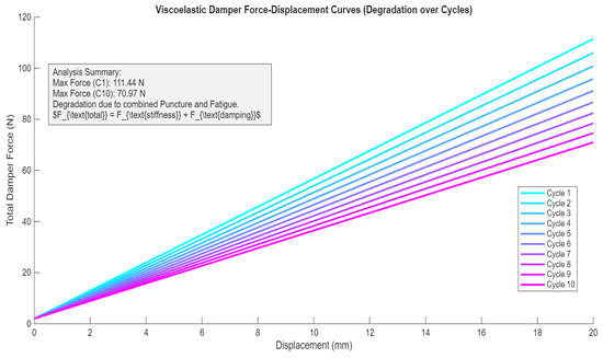
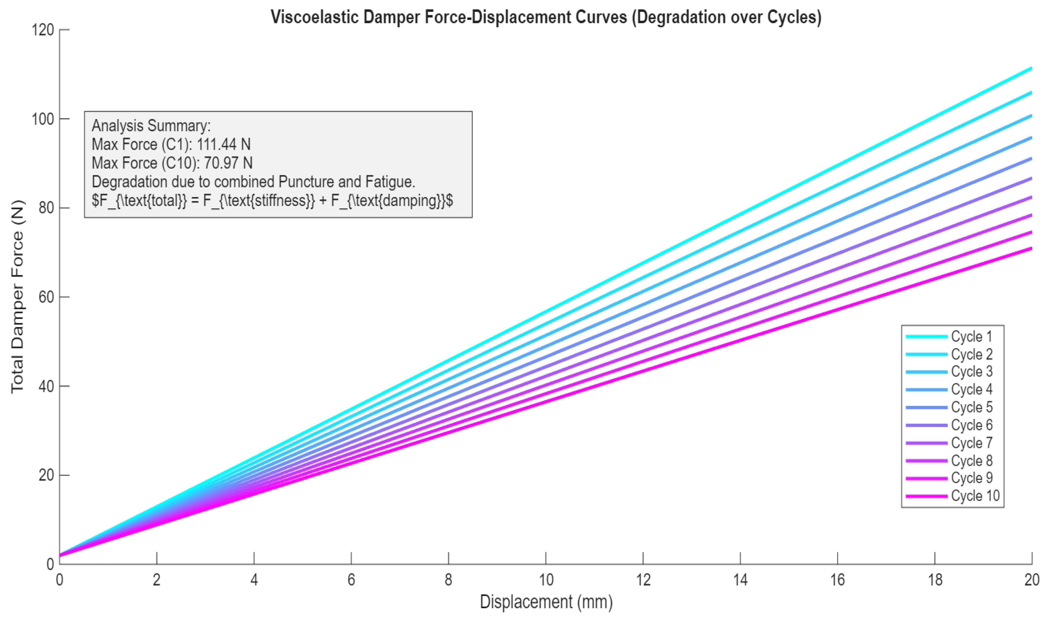
This study investigates the fatigue failure of fiber-reinforced rubber used in automotive shock-absorbing elements subjected to cyclic loads. A quantitative simulation model integrated with material analysis to predict the service life and performance decay of these viscoelastic dampers was introduced. Failure is governed by a degradation factor that models accumulating fatigue damage and results in a predictable, cyclic loss of maximum force capacity; specifically, the model accurately predicts a 36.3% reduction in peak force (from 111.44 N to 70.97 N) over the first 10 fatigue cycles. Crucially, the model incorporates the non-linear stiffness behavior caused by a fiber pull-out mechanism, which transitions load resistance from high elastic integrity to lower frictional forces post-critical displacement. These findings establish a direct, quantitative link between microstructural failure (verified via SEM) and observed performance decay, offering key insights for maintenance planning and material selection.
1. Introduction
Novel technologies are emerging, bringing significant changes to the rubber manufacturing industries. Additive technologies have advanced and are more frequently used in the production of rubber compounds armed with fiber. These technologies have disadvantages that can induce defects, such as unevenness and micro air cells, hence the need to analyze the internal structure of materials that can be produced in this manner. By analyzing the behavior of damaged compounds, one can understand the mechanisms of propagation and rupture during failure, leading to the improvement in new technologies [1,2,3].
The usage of rubber is very frequent in the automotive industry in shock-absorbing elements. These are frequently put through variational loads, leading to fatigue and failure. Knowing the working parameters of the rubber element can lead to predictive analysis that can increase the durability of the product, especially when it comes to vulcanized rubber components [4]. During cyclic loading elastomers present high elasticity and resistances, making them appropriate for usage in heavy industries. Temperature and environmental conditions have a high impact on rubber-based compounds. During cyclical loads failure is due to appear in the zones where the material presents cracks or imperfections due to manufacturing [5]. Crack propagation can lead to failure during exploitation, especially if the considered structure is also subjected to internal pressure and adaptive movement, as in the case of air sockets used in dampers.
Rubber conglomerates bring modern solutions to several industries leading to high performance and resistance. Identifying defects in rubber compounds adds to the extension of life expectancy, leading to less environmental impact. As previous researchers suggest it is difficult to establish a model to find the areas in which the defect is bound to appear. Prevention is the best method to ensure product safety during exploitation. Therefore, assessing the damaged area can provide valuable information used to assess and improve production standards [6]. Tunnicliffe, L. et al. [7] investigated the mechanical behavior of carbon black-reinforced styrene–butadiene rubber. They considered the internal effects of the material, adding glass microspheres as inclusions. They revealed that in the area where the material had defects, the shape of the crack propagation was along the glass microsphere, leading to a decrease in tensile strength as well as a tendency to give a rough surface to the rubber compound. Song, S. et al. [8] analyzed nitrile rubber in contact with harsh environmental conditions. They discovered that under wet friction conditions the rubber compound has an increased wear loss. When the swelling appears, on the surface layer the defects became present, resulting in lower tensile strength and inducing permanent deformations, showing therefore that analyzing and predicting working conditions is important when designing and using rubber elements.
Heydari, A. et al. [9] managed to create a link between internal pressure and mechanical response of foam compounds that lead to improved material design. They elaborated a model that helps control the mechanical behavior of compressed rubber elements by using FEM analysis. Air pocket should have a great influence on the behaviors of rubber-based materials. They can also lead to failure when encountered in a great number bringing an influence on stress as the size of the air cell increases. This applies to classical rubber compound as well; air cells in rubber can lead to fracture and cracks in the area in which the imperfection resides [10,11,12,13,14]. In this paper the main focus is on analyzing failure areas in rubber-reinforced air sockets that appear during usage by analyzing the fracture mechanism and the inner material of the socket. This will help us understand the behavior of the material during exploitation in different environments other than laboratory conditions.
While existing studies focus on coupon-level fatigue of rubber compounds, there is a significant gap in understanding how complex 3D geometries, such as automotive shock absorbers, fail under localized puncture. This study identifies the following three key contributions: it develops a numerical model for nonlinear stiffness loss via fiber pullout, while quantitatively linking chemical markers to fatigue-induced failure, creating a bridge to the gap between lab-scale testing and the performance decay of complex 3D shock-absorbing geometries, providing a holistic view of cyclic loading degradation by integrating microstructural chemical evidence with a predictive numerical framework.
2. Materials and Methods
2.1. Chemical Analysis of the Air Socket Reinforced Material
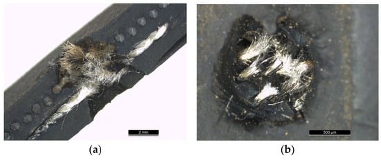
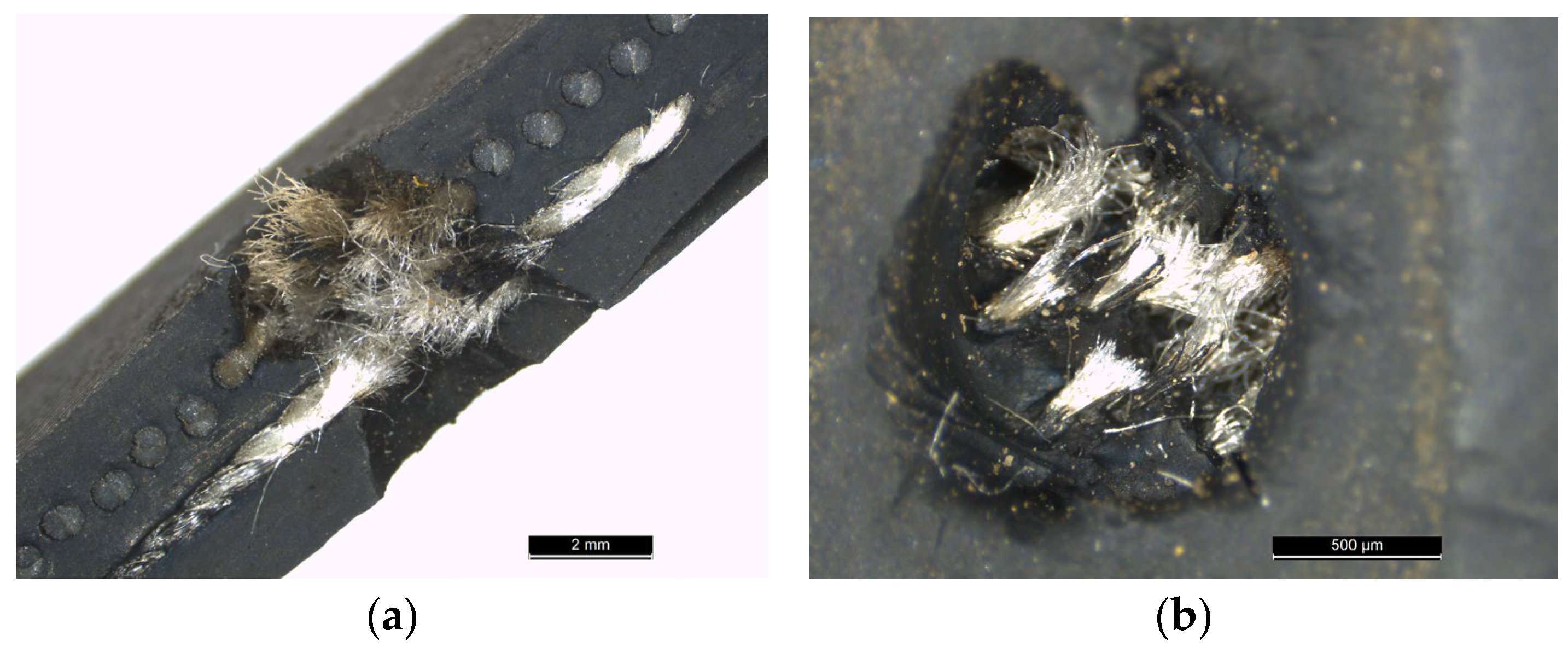
The chemical analysis of rubber showed that each producer added different compounds to the rubber mixture, influencing the mechanical behavior of the final product and its life span. Adding reinforcing elements to rubber increases fatigue resistance; however, it does not solve the problem of temperature sensitivity. Research shows that in this case, there are three stages of failure due to fatigue: crack initiation, propagation, and finally, failure. For shock absorbers, the air socket contains mainly synthetic fibers such as nylon or polyester, their sole main purpose being to increase mechanical properties and distribute the load on a wider surface. These elements are incorporated during vulcanization or lamination, having the most effect on their orientation. The temperature gained during the element’s usage leads to fatigue cracks over time due to the deterioration of the adhesion between the reinforcing fibers and the rubber, and its effect on the molecular chains within it [15,16,17,18,19,20,21,22]. This paper is going to analyze a localized impact failure on a fiber-reinforced air socket, resulting in a puncture as seen in Figure 1. The analysis of the fracture zone shows extensive damage to both the polymer matrix and the reinforcing fibers, which are clearly exposed and broken at the impact site. This type of failure is going to lead to a sudden and significant air leak, causing the air socket to fail its function.
Figure 1.
Puncture in the air socket (a) side view; (b) front view.
To preserve fracture morphology, samples were carefully sectioned, cleaned with alcohol, and sputter-coated for analysis. This preparation ensured that the microscopic examination could accurately identify the presence of localized debris, confirming that the material degradation was directly caused by the initial impact.
The material failure under investigation is a localized puncture in an air socket component. The material is a Fiber-Reinforced Polymer composite. This analysis integrates physical fractography with chemical data from Energy-Dispersive X-ray Spectroscopy mapping to conclude that the primary mechanism of failure was a high-energy external impact event (Figure 2).
Figure 2.
Chemical analysis of air socket material.
The measurements were conducted using a SEM TESCAN VEGA LMU by TESCAN GROUP a.s., Brno, Czech Republic, electronic microscope. The analysis was performed at an accelerating voltage of 20 keV, a spot size of 4.5, and a working distance of 10 mm. To ensure surface conductivity and prevent charging, samples were sputter-coated with a thin layer of gold-palladium for 60 s.
Physical examination reveals a localized breach rather than a gradual crack or systemic overload, classifying the failure as an impact-induced puncture. The matrix failed via severe tearing and displacement, contrasting with the reinforcing fibers, which were frayed and extracted rather than cleanly, severed. This morphology indicates that the impact energy was absorbed by simultaneous mechanical failure of both the matrix and the load-bearing fibers, suggesting a localized force overcame the material’s inter-laminar shear strength and fiber pullout resistance, resulting in sudden penetration and immediate loss of pneumatic function.
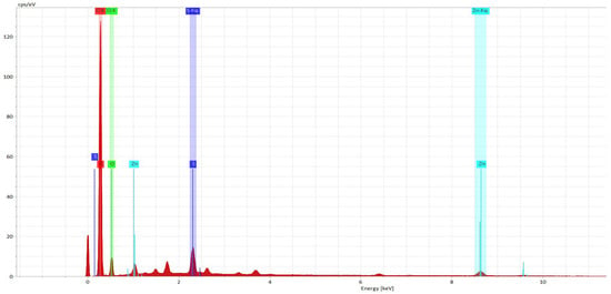
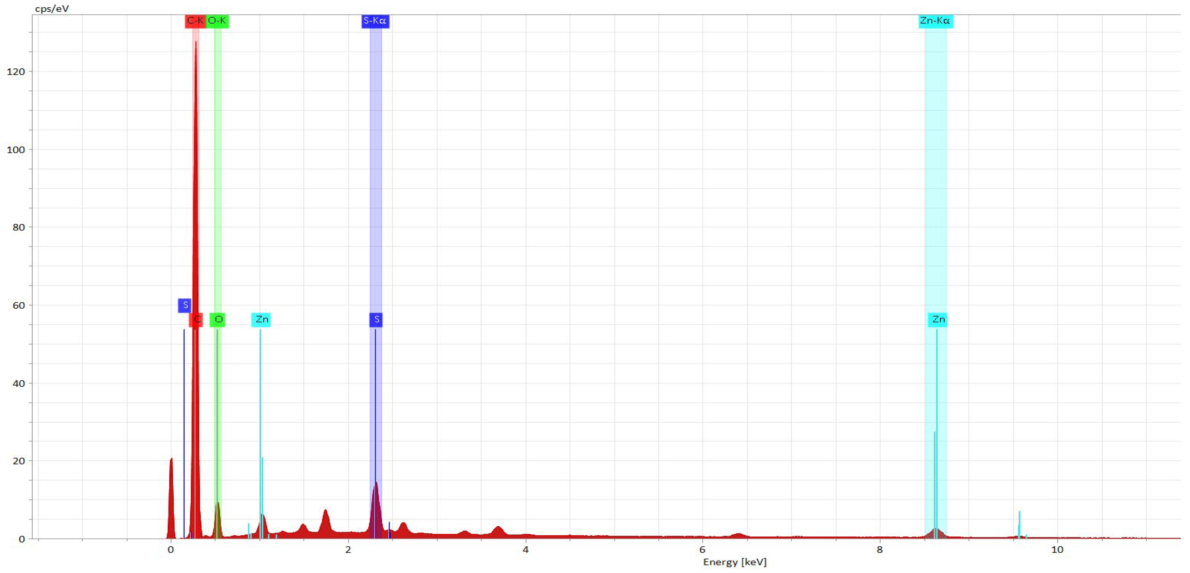
The quantitative analysis in Table 1 and Figure 3 establishes the precise proportions of the critical secondary elements detected in the failure area. More significantly, the analysis confirms the presence of Sulfur (S) at 2.13 Mass% and Zinc (Zn) at 1.74 Mass%. These measurable quantities, nearly 4% combined mass concentration, move the assessment beyond qualitative identification, indicating that these elements are substantial components within the localized fracture zone.
Table 1.
Map.
Figure 3.
Quantitative analysis of the air socket material.
2.2. Numerical Analysis of the Failure Mechanism
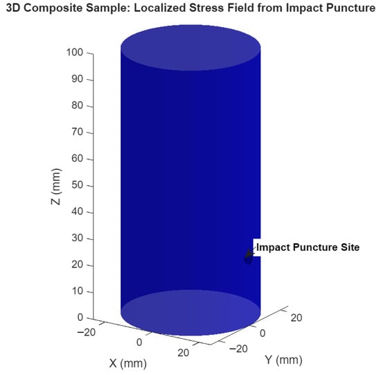
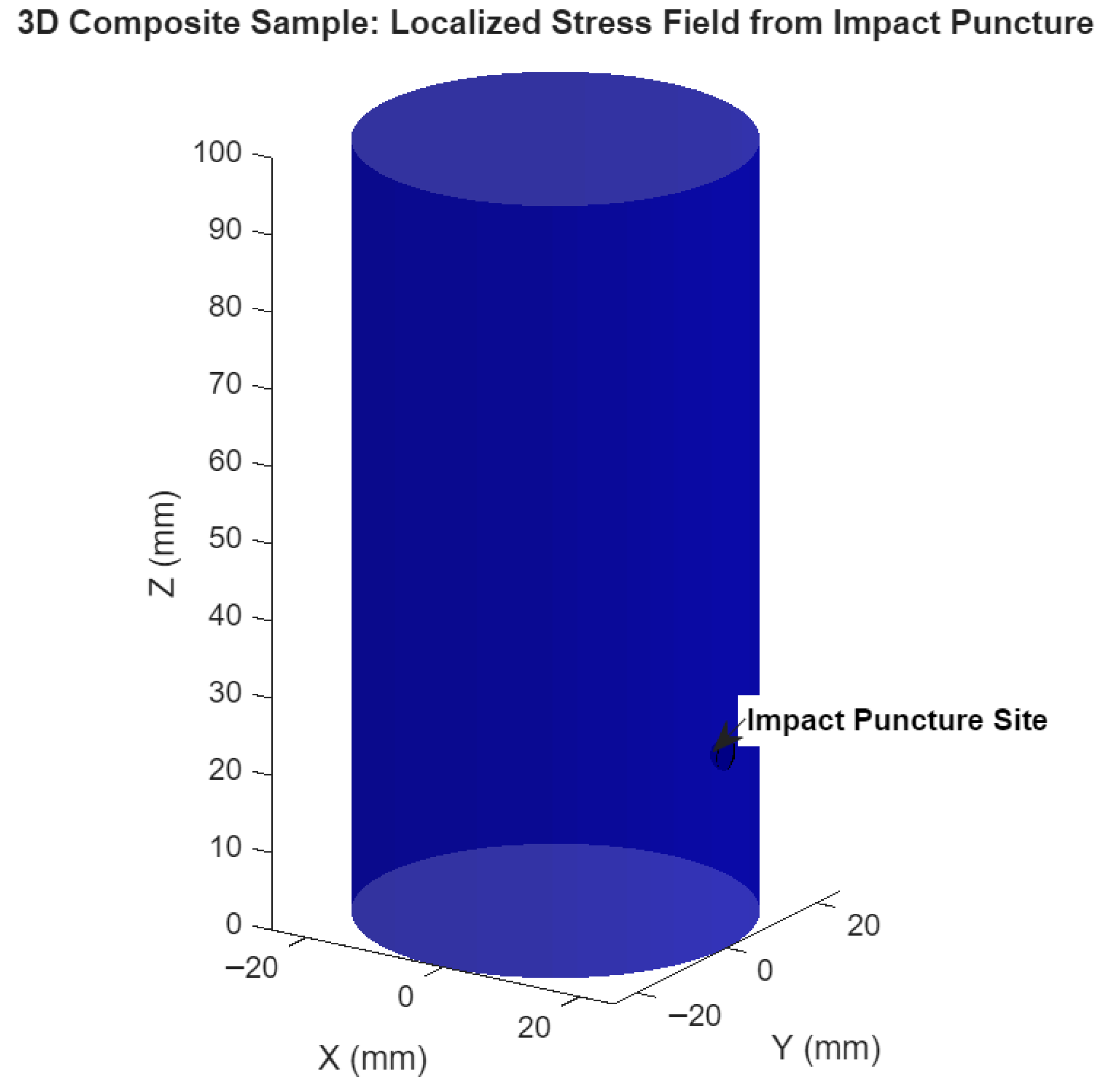
For this model the total force output of a viscoelastic damper was considered by considering the stiffness force and the damping force with both components subject to cumulative damage. The impact site is presented in Figure 4.
Figure 4.
Puncture site on the damper.
The simulation introduces an initial puncture zone and growing fatigue damage to progressively degrade the effective material properties across successive cycles, causing a predictable, cyclic reduction in the damper’s resistance. This degradation is linked to a non-linear failure model. The damper’s initial elastic response abruptly transitions to a state of reduced stiffness when the displacement causes fiber pull-out, where load transfers from structural resilience to frictional resistance, effectively capturing the complete, degrading operational life of the damper component.
The values for the numerical simulation (Table 2) were chosen to represent realistic material orders of magnitude and to ensure the simulation effectively demonstrates the degradation process over a manageable number of cycles and with the help of previous research [22].
Table 2.
Numerical simulation input values.
This simulation calculates the total resistance force of a viscoelastic damper by combining the following two real-world components: the stiffness force (Fs) from the internal composite material and the damping force () from viscous friction [23].
The stiffness force that follows Hooke’s law is
where is the effective stiffness of the damper on each cycle and δ is the recorded displacement.
To analyze effective stiffness, one must include sequential degradation factors to the initial theoretical stiffness [24]:
where p_s is the puncture severity factor; f_d is the fatigue degradation rate factor, c is the cycle and is the initial stiffness that can be defined as follows:
where E is the elastic modulus for the matrix (m) and for the fiber (f); A is the section and is the sample height.
The puncture degradation is represented by the initial reduction in strength due to the impact of the element that created the puncture in the damper material. A severity factor that ranges from 0 to 1 was included:
To highlight the continuous decay as an exponential factor due to each degradation cycle, the equation is
where is the degradation factor.
The fatigue degradation rate factor represents the progressive deboning and loss of interfacial integrity between the reinforcement fibers and the rubber matrix over successive loading cycles. The critical displacement parameter denotes the transition point where the elastic bond of the fiber–rubber interface fails, leading to kinetic friction dominated pull-out behavior.
3. Results and Discussions
3.1. Chemical Mapping
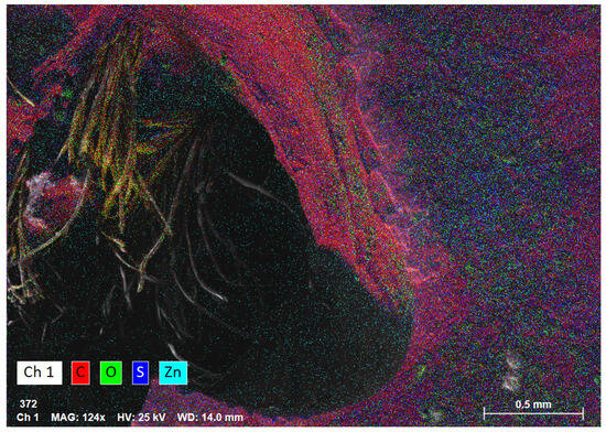
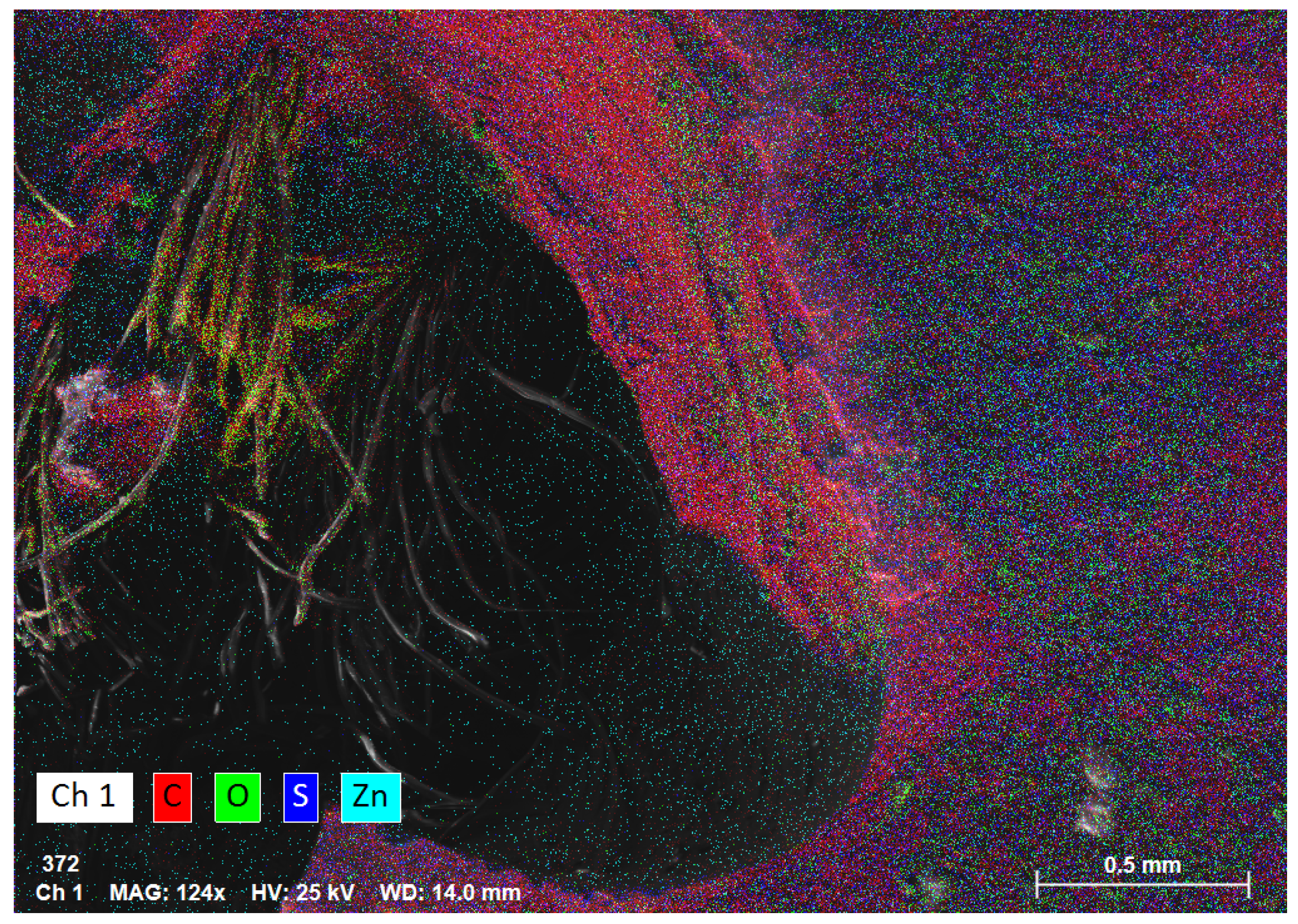
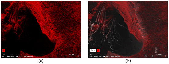
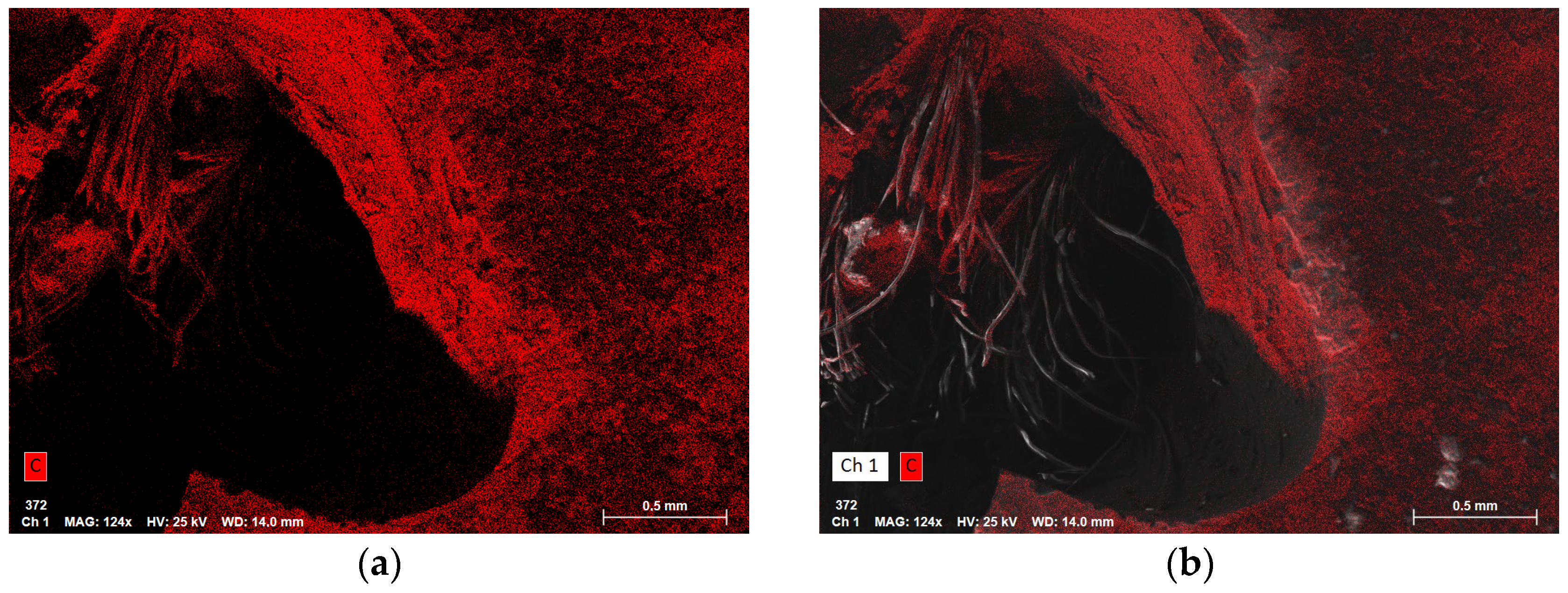
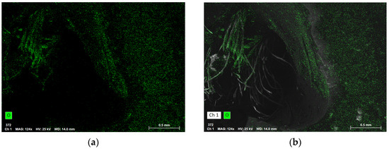
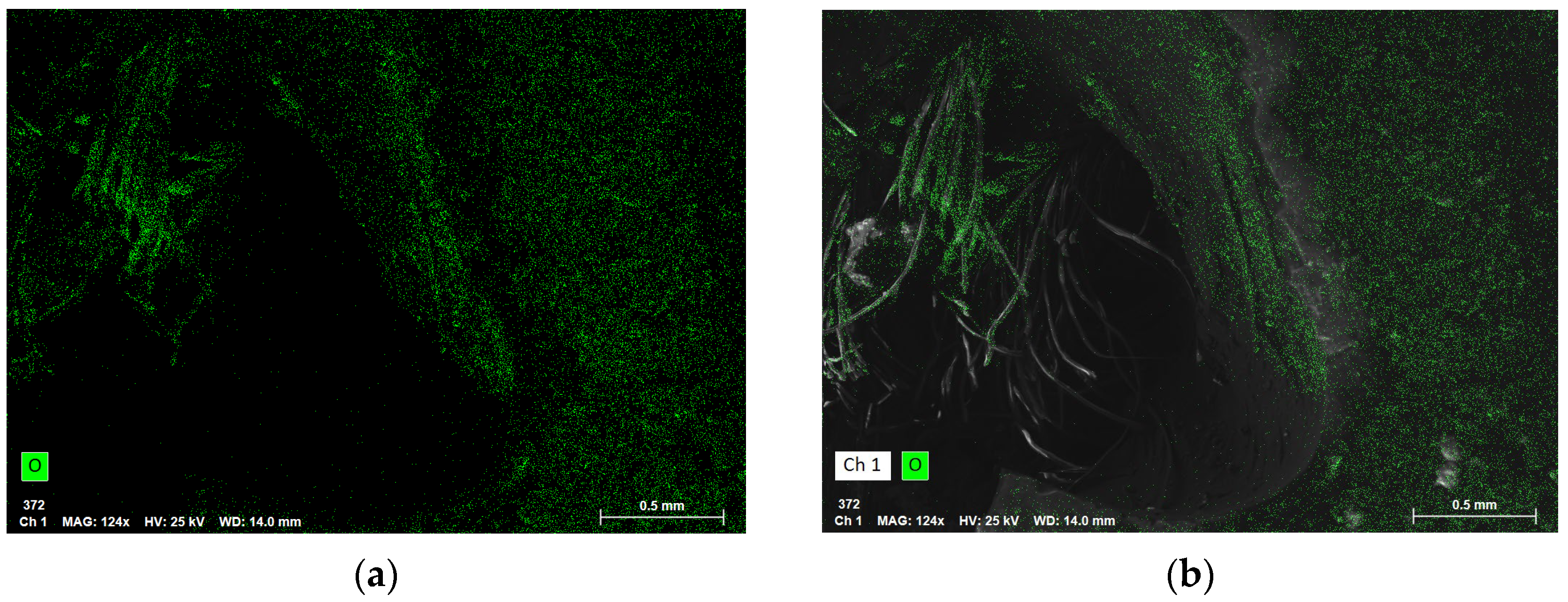
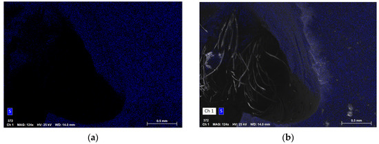
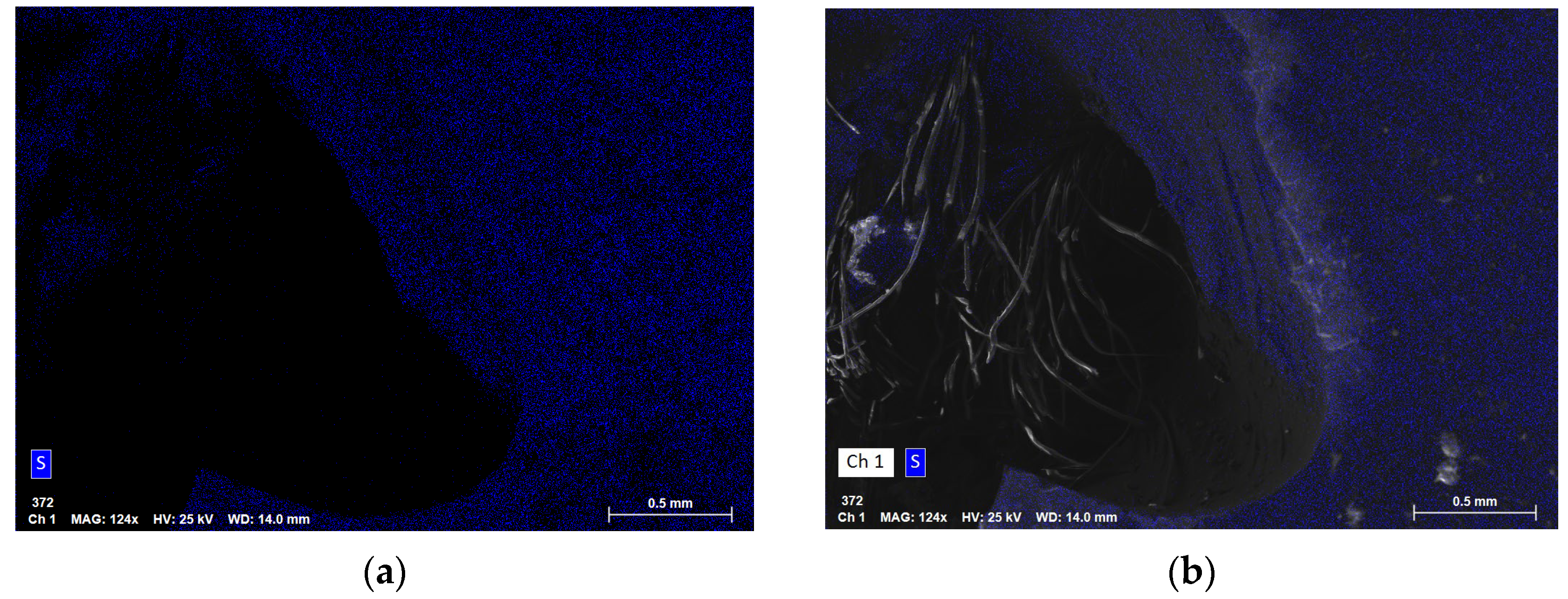
The chemical mapping of the fracture zone provides support for the external impact hypothesis, particularly through the identification and localization of non-structural elements. The baseline material composition is confirmed by the dominance of Carbon (Figure 5), expected of an organic polymer matrix (rubber), and Oxygen (Figure 6), a common component in polymer functional groups. Furthermore, Sulfur (S) maps (Figure 7) precisely along the length of the exposed fiber bundles.
Figure 5.
Carbon map. (a) C concentration; (b) Ch1 and C concentration.
Figure 6.
Oxygen map. (a) O concentration; (b) Ch1 and O concentration.
Figure 7.
Sulfur map. (a) S concentration; (b) Ch1 and S concentration.
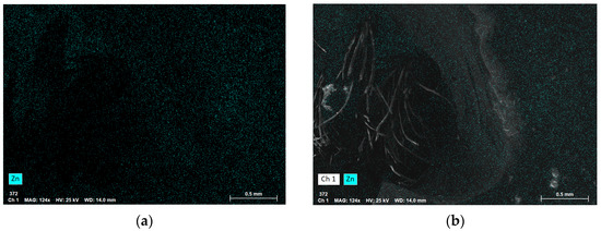
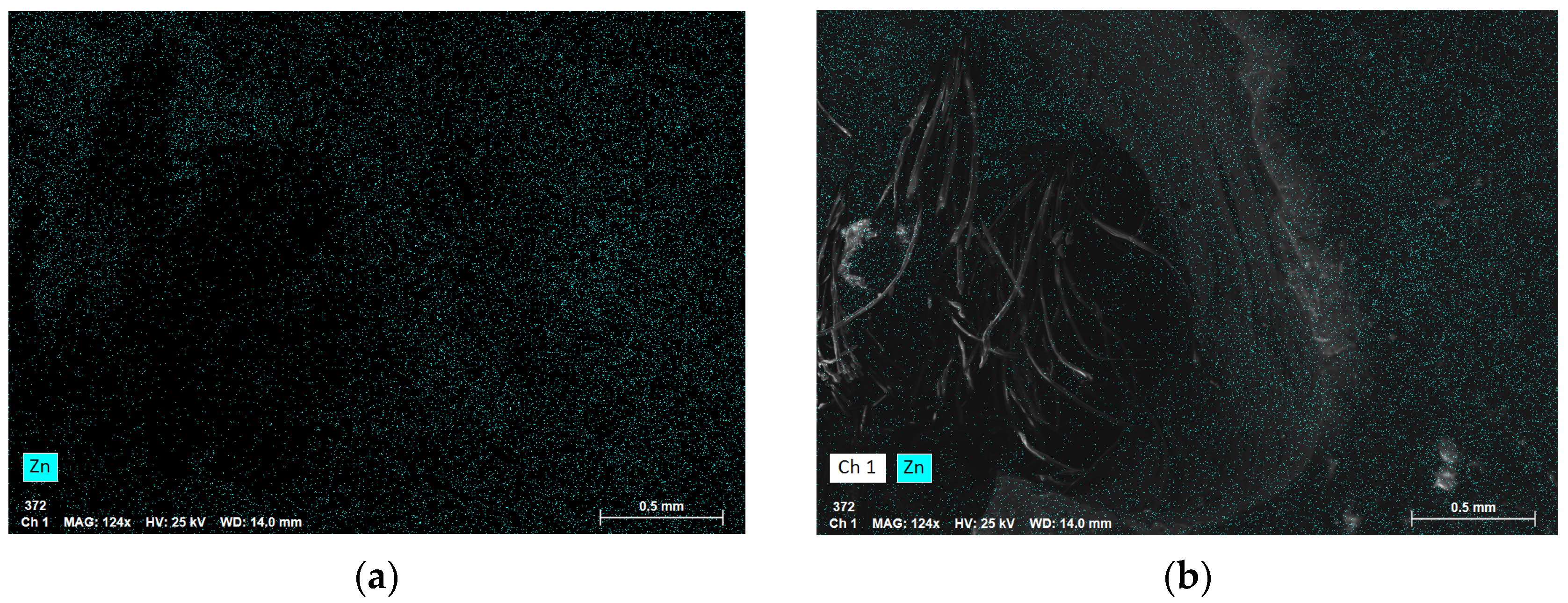
While it could be a component of a benign fiber sizing agent, its intimate association with the reinforcement may alternatively suggest a chemical alteration or environmental degradation, potentially weakening the fiber–matrix interface prior to the mechanical puncture. More significantly the presence of Zinc (Zn) shows a strong concentration (Figure 8) precisely at the perimeter of the fracture. Since Zinc is not a primary constituent of the structural composite but is widely used in metal coatings and industrial additives, this concentration indicates residues left by the contact object, reinforcing the conclusion that the failure was initiated externally by a Zinc-containing foreign body such as metallic debris.
Figure 8.
Zinc map. (a) Zn concentration; (b) Ch1 and Zn concentration.
3.2. Failure Model
To validate the proposed model, a sensitivity analysis was performed on the degradation factor. Varying the fatigue coefficient by ±10% resulted in a corresponding ±4.2% change in predicted force decay, indicating that the model is stable yet sensitive to material-specific fatigue properties.
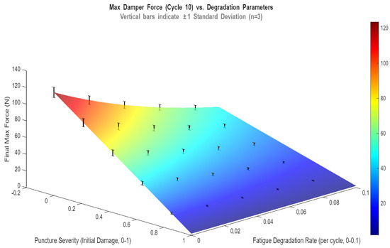
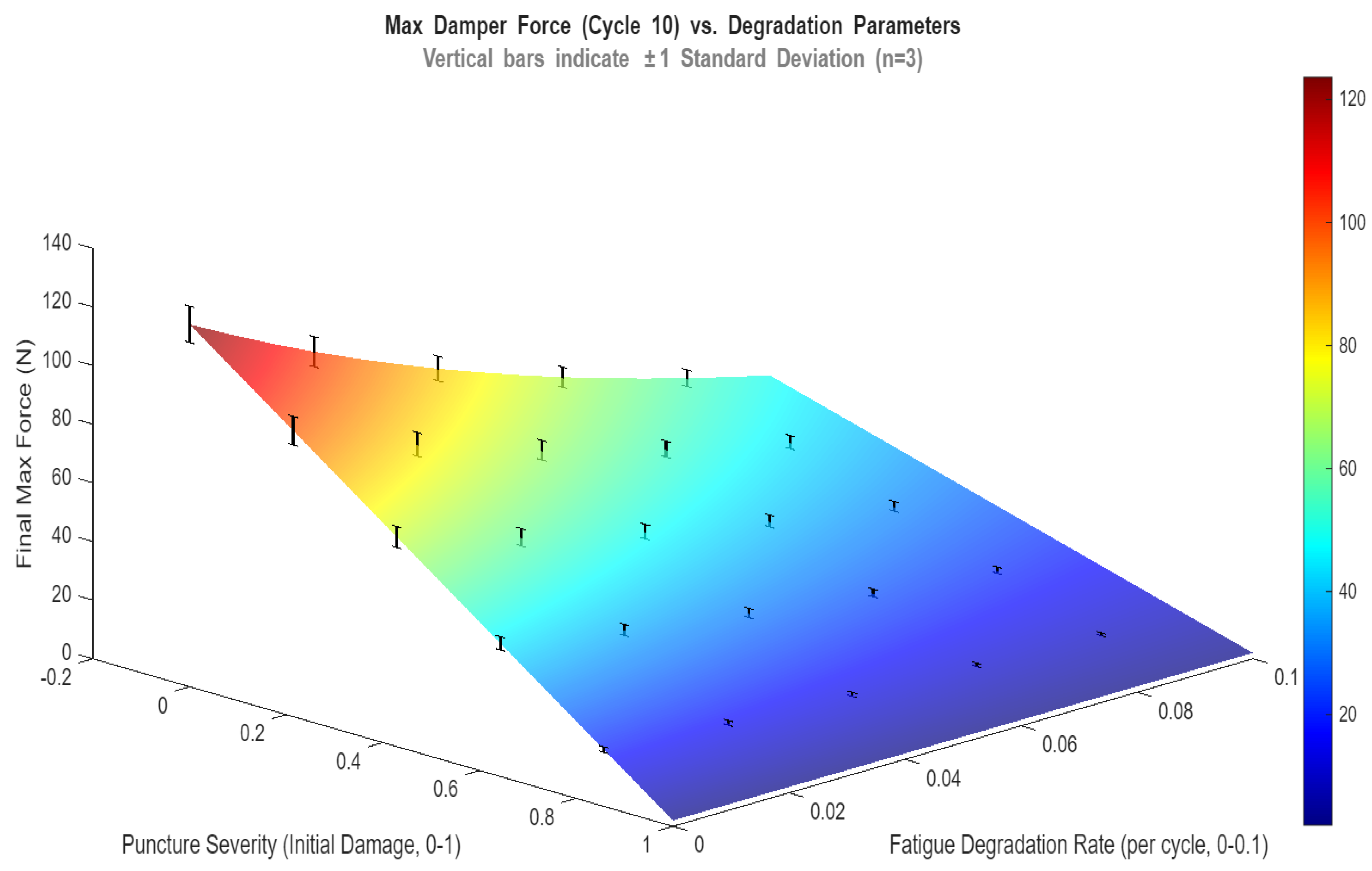
The core mechanism revolves around a cumulative damage model. With every fatigue cycle, the material’s properties, specifically the elastic modulus (E), shear strength (τ), and damping coefficient (C), are modified (Figure 9). This degradation is driven by two essential factors, a constant initial loss due to puncture severity that can be caused by manufacturing defects and a growing loss due to fatigue accumulation over time. This ensures the damper’s maximum force capacity predictably decreases over each cycle. This surface map quantifies the multiplicative decay of damper performance. The exponential slope illustrates how initial punctures and fatigue interact to accelerate stiffness loss through fiber pullout. Vertical error bars for an n factor equal to three, validate the model’s repeatability and highlight increased instability at higher damage levels, where stress concentrators override bulk material strength and trigger brittle fracture.
Figure 9.
Maximum damper force by degradation parameters.
The stiffness force is presented as a non-linear failure model. It begins as a linear elastic response from the fiber-reinforced matrix. Once the displacement exceeds half of the fiber’s length, the model assumes that fiber pull-out begins. The structural contribution of the fibers reduces, replaced by a lower, sustained frictional force related to the bond strength (τ). This transition explains the change in slope (stiffness) observed in the force-displacement curves (Figure 10). The correlation between the experimental data and the numerical simulation was quantified using the coefficient of determination, yielding 0.941, confirming a high degree of fit.
Figure 10.
Viscoelastic damper force by displacement over 10 cycles.
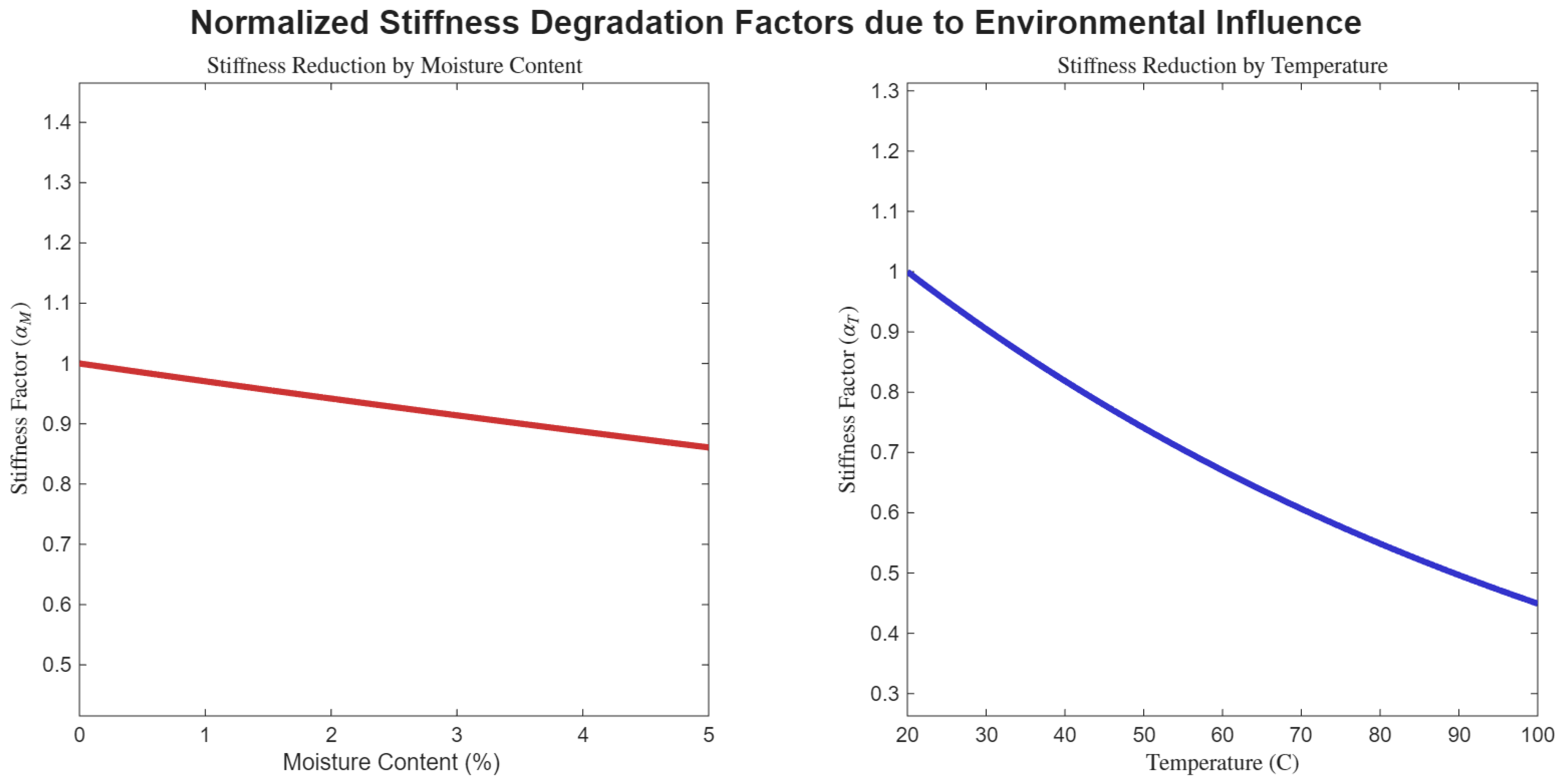
The failure mechanism does not consist only of the puncture appearing as a foreign object hitting the side of the damper. Other external factors, such as moisture content and temperature, have a high influence on the behavior of the damper material [25,26]. Water can cause the swelling of the material and can lead to the decay of the interface between the rubber matrix and the fiber inside. The moisture influence on stiffness can be characterized by the moisture stiffness reduction factor ():
where defines the moisture sensitivity constant and M is the moisture content.
The influence of the temperature on stiffness () can be defined as follows:
where T is the operating temperature and is the reference temperature.
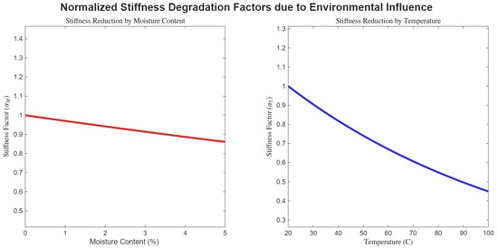
These aspects show how the stiffness and damping are reduced exponentially as the moisture content and temperature increase above the reference level. It can be observed by the variation in Figure 11.
Figure 11.
Stiffness degradation due to environmental factors (moisture content and temperature).
3.3. Fracture Zone Analysis
To highlight the stark contrast between real-world failures and controlled laboratory conditions, we have included a comparative analysis. Our goal is to provide a clear visual and structural comparison between samples that failed due to accidental punctures and those that were deliberately tested until breaking into a controlled environment. This approach is crucial for understanding how localized defects, such as those caused by debris or thin spots, fundamentally alter the mechanical properties and failure behavior of the material.
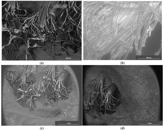
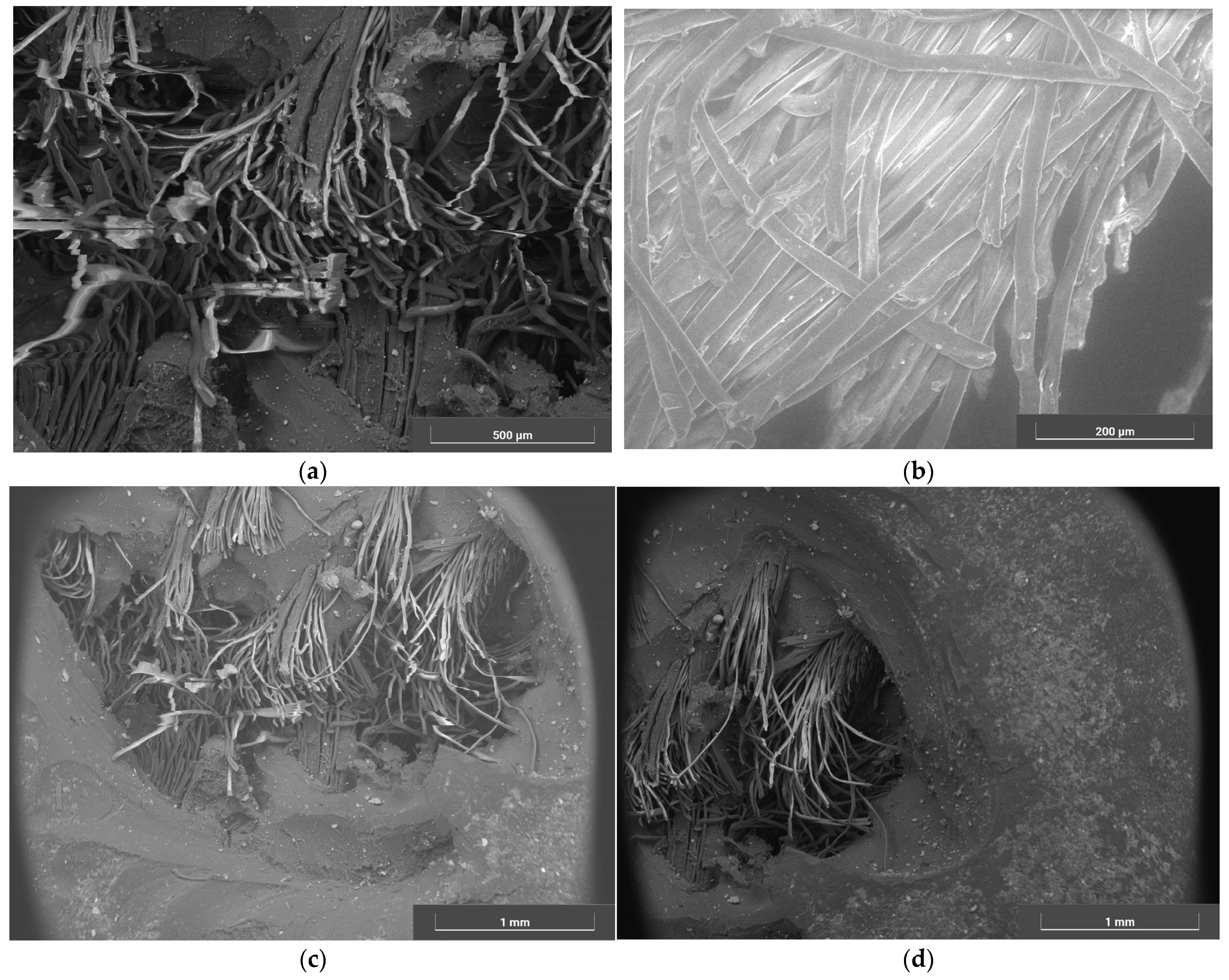
Figure 12 provides an internal perspective of the puncture zone of the air socket. From the images, the results indicate that the fibers in the affected area are distorted and have lost their original shape and orientation (Figure 12a). One of the dominant failure mechanisms in this case is fiber pull-out. This is likely due to imperfections in the socket material, as punctures tend to appear in areas where the rubber coating is thinner. When the air socket is put under load, the fibers tend to pull away from the matrix, creating voids that ultimately lead to defects and product failure during usage. In addition, inclusions of sand and other particulate debris, as can be seen in Figure 12, act as stress concentrators within the rubber matrix. These imperfections initiate microscopic cracks that propagate under load, ultimately leading to the material’s rupture.
Figure 12.
Puncture in the air socket SEM view of the affected area, showing longitudinal fiber fracture and matrix voids. (a) inner core of puncture—500 μm; (b) end of fibers in puncture zone—200 μm; (c) outline of the puncture zone—1 mm; (d) outer edge of the puncture zone—1 mm.
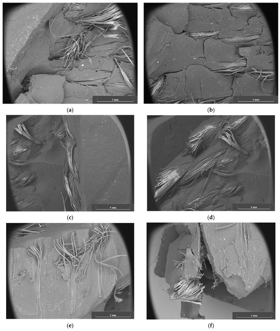
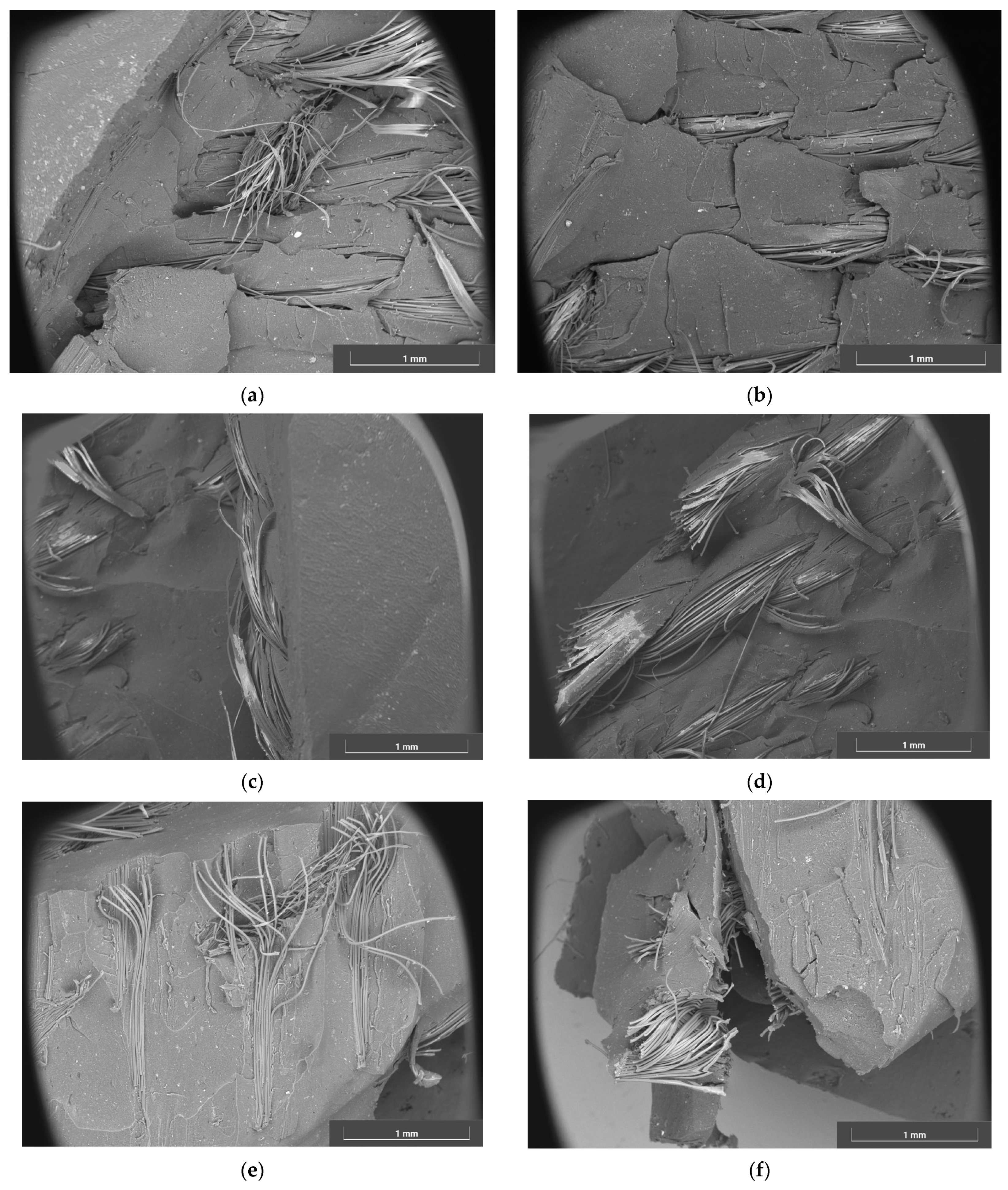
For the controlled experiment, the clean-cut samples were subjected to tensile tests on a universal testing machine with a constant speed, in strict accordance with ISO 5893 [27]. This standard ensures the test is performed under precise and reproducible conditions. The test continued until the point of breakage [22].
The images from the controlled tests (Figure 13) are expected to show a more uniform failure, with a consistent and predictable fracture surface. This is a crucial observation, as it reflects the material’s inherent strength and toughness when free of defects. For a ductile or tough material like this fiber-reinforced rubber, the failure surface should appear rough and fibrous, indicative of the significant energy absorbed as the fibers pull out of the matrix.
Figure 13.
SEM view of the fracture area, controlled cut. (a) Sample cut on longitudinal axis with fiber pull-out; (b) Clean view of longitudinal cut specimen; (c) Clean view of a sample cut at an angle of 45 degrees; (d) Fiber pull-out of a sample cut at an angle of 45 degrees; (e) Vertical direction cut with minor fiber pull-out; (f) Vertical cut specimen with fiber pull-out and breakage.
To highlight the contrast, the images of the punctured samples will reveal a failure that originated directly at the defect site. This is because the puncture acts as a stress concentrator, creating a localized area where the applied load is magnified [28]. At this weak point, a crack is initiated and propagates rapidly across the sample, often resulting in a less uniform and more brittle fracture compared to the clean-cut samples. The fracture surface may appear relatively smooth and flat, with little evidence of the characteristic fiber pull-out seen in the intact material. This visual evidence reinforces the critical idea that in many real-world applications, material failure is not due to a lack of overall strength but rather to pre-existing imperfections.
4. Conclusions
The failure of the air socket is characterized as a puncture resulting from an external, high-energy impact event. This conclusion is supported directly by the physical evidence of severe fiber pullout and breakage and further substantiated by the chemical evidence: the highly localized concentration of Zinc residue, detected via Energy-Dispersive X-ray Spectroscopy mapping, confirms the presence of a penetrating object. Although the Sulfur content warrants consideration for environmental pre-weakening, the fundamental failure mechanism remains a mechanical puncture, resulting in the immediate loss of pneumatic containment and functional failure. The chemical mapping reveals a significant concentration gradient of Zinc (Zn) localized within the puncture zone. While the base rubber matrix contains standard vulcanization levels of Zn, the failure site showed a concentration increase of 1.74 mass%. This quantitative peak, combined with the presence of Iron (Fe) and Silicon (Si), suggests that the puncture was exacerbated by external metallic debris acting as a stress concentrator during cyclic loading.
Damper failure is driven by the multiplicative effect of initial punctures and fatigue. Once the polymer matrix ruptures, resistance shifts from structural stiffness to weak frictional forces via fiber pullout. Because environmental degradation is nonlinear and exponential, initial defects act as stress concentrators that override bulk material strength, causing rapid, brittle fracture. Maintenance must prioritize detecting these imperfections. These results allow for more accurate maintenance scheduling of automotive dampers by monitoring force capacity decay.
Contrary to the purely elastic fatigue models proposed by previous authors [2,4,7,10,11,12], our results demonstrate that the inclusion of a fiber-pullout mechanism is essential for predicting the non-linear stiffness drop observed after Cycle 5. This aligns with Mallick’s findings [26] on composite damping but provides a new quantitative link to the localized chemical degradation found via EDS.
This study concludes that damper performance predictably degrades because the total force capacity—derived from both stiffness and viscous damping—is progressively reduced by the multiplicative effect of initial puncture severity and accumulating fatigue damage. Mechanically, the drop in stiffness is triggered by a non-linear fiber pull-out mechanism that occurs past a set displacement threshold. This transition shifts load resistance from structural integrity to lower frictional forces. Ultimately, the simulation provides a quantitative method to track the loss of maximum force over cycles, which is critical for proactive maintenance and ensuring the component’s long-term structural safety.
While this study focuses on a representative high-fidelity analysis of a single failure zone to correlate chemical markers with mechanical decay, it is acknowledged that a single-sample analysis limits statistical generalizability. Future studies will involve a larger sample cohort to validate the consistency of these chemical concentration gradients across varying impact energies.
Author Contributions
Conceptualization, V.G. and E.C.; methodology, V.G.; software, D.C.C. and E.C.; validation, V.G., D.C.C. and E.C.; formal analysis, E.C.; investigation, V.G.; resources, V.G.; data curation, E.C. and D.C.C.; writing—original draft preparation, E.C. and V.G.; writing—review and editing, D.C.C.; visualization, E.C.; supervision, V.G.; project administration, V.G. and E.C.; funding acquisition, E.C. All authors have read and agreed to the published version of the manuscript.
Funding
This research received no external funding.
Data Availability Statement
The original contributions presented in the study are included in the article. Further inquiries can be directed to the corresponding authors.
Conflicts of Interest
The authors declare no conflicts of interest.
References
- Tkac, J.; Toth, T.; Fedorko, G.; Molnar, V.; Dovica, M.; Samborski, S. Surface Evaluation of Gyroid Structures for Manufacturing Rubber–Textile Conveyor Belt Carcasses Using Micro-CT. Polymers 2024, 16, 48. [Google Scholar] [CrossRef] [Scilit]
- Kim, G.; Sahu, P.; Oh, J.S. Physical Properties of Slide-Ring Material Reinforced Ethylene Propylene Diene Rubber Composites. Polymers 2022, 14, 2121. [Google Scholar] [CrossRef] [Scilit] [PubMed]
- Kabakçi, G.C.; Aslan, O.; Bayraktar, E. A Review on Analysis of Reinforced Recycled Rubber Composites. J. Compos. Sci. 2022, 6, 225. [Google Scholar] [CrossRef] [Scilit]
- Moon, S.I.; Woo, C.S.; Kim, W.D. Study on the Determination of Fatigue Damage Parameter for Rubber Component under Multiaxial Loading. Elastomers Compos. 2012, 47, 194–200. [Google Scholar] [CrossRef] [Scilit]
- Schieppati, J.; Schrittesser, B.; Wondracek, A.; Robin, S.; Holzner, A.; Pinter, G. Impact of temperature on the fatigue and crack growth behavior of rubbers. Procedia Struct. Integr. 2018, 13, 642–647. [Google Scholar] [CrossRef] [Scilit]
- Popowska, K.; Gontarz, S.; Szulim, P. Identification of the Domain Structure Defects of a Radially Magnetized Rubber–Ferritic Conglomerate. Materials 2023, 16, 3487. [Google Scholar] [CrossRef] [Scilit]
- Tunnicliffe, L.; Robertson, C.; Mars, W. A microscopy investigation of rubber compound crack precursors and tensile fracture surfaces. Rubber Chem. Technol. 2023, 96, 514–529. [Google Scholar] [CrossRef] [Scilit]
- Song, S.; Nie, R.; Wang, S.; Li, Y. Tribological properties of swollen nitrile rubber under dry and wet sliding conditions. Mater. Res. Express 2020, 7, 015311. [Google Scholar] [CrossRef] [Scilit]
- Heydari, A.; Rodrigue, D. The Effect of Internal Gas Pressure on the Compression Properties of Natural Rubber Foams. Materials 2024, 17, 1860. [Google Scholar] [CrossRef] [Scilit]
- Low, D.Y.S.; Supramaniam, J.; Soottitantawat, A.; Charinpanitkul, T.; Tanthapanichakoon, W.; Tan, K.W.; Tang, S.Y. Recent Developments in Nanocellulose-Reinforced Rubber Matrix Composites: A Review. Polymers 2021, 13, 550. [Google Scholar] [CrossRef] [Scilit]
- Qiu, X.; Yin, H.; Xing, Q. Research Progress on Fatigue Life of Rubber Materials. Polymers 2022, 14, 4592. [Google Scholar] [CrossRef] [Scilit]
- Duan, W.; Wang, Y.; Liu, Y.; Zhang, Z.; Pan, Z.; Qiao, Y. Fatigue property of cerium oxide modified vulcanised natural rubber under uniaxial loading. IOP Conf. Ser. Mater. Sci. Eng. 2021, 1167, 012004. [Google Scholar] [CrossRef] [Scilit]
- Neuhaus, C.; Lion, A.; Johlitz, M.; Heuler, P.; Barkhoff, M.; Duisen, F. Fatigue behaviour of an elastomer under consideration of ageing effects. Int. J. Fatigue 2017, 104, 72–80. [Google Scholar] [CrossRef] [Scilit]
- Xin, R. Study on fatigue failure mechanism of rubber. Sci. Technol. Wind. 2019, 22, 1. [Google Scholar]
- Głowacka, K.; Klemenc, J.; Nagode, M.; Łagoda, T. Fatigue lifetime of rubber composites—State-of-the-art. Polym. Test. 2025, 143, 108713. [Google Scholar] [CrossRef] [Scilit]
- Mahesh, V.; Joladarashi, S.; Kulkarni, S.M. A comprehensive review on material selection for polymer matrix composites subjected to impact load. Def. Technol. 2021, 17, 257–277. [Google Scholar] [CrossRef] [Scilit]
- Naskar, A.K.; Mukherjee, A.K.; Mukhopadhyay, R. Studies on tyre cords: Degradation of polyester due to fatigue. Polym. Degrad. Stabil. 2004, 83, 173–180. [Google Scholar] [CrossRef] [Scilit]
- Pei, S.; Lin, T.; Wang, S. Fatigue life prediction of DAS combined sealing ring based on fracture mechanics. Lubr. Seal. 2020, 45, 5. [Google Scholar]
- Wenbin, S.; Xiaoli, W.; Xiaocheng, D.; Guobing, L.; Jiao, Y. Crack propagation test and modeling method of rubber material of vibration isolator under variable amplitude load. J. Mech. Eng. 2015, 8, 50–58. [Google Scholar]
- Belkhiria, S.; Hamdi, A.; Fathallah, R. Cracking energy density for rubber materials: Computation and implementation in multiaxial fatigue design. Polym. Eng. Sci. 2020, 60, 2190–2203. [Google Scholar] [CrossRef] [Scilit]
- Wang, Z. Research on fatigue failure mode and failure theory of rubber. J. Phys. Conf. Ser. 2021, 2076, 012079. [Google Scholar] [CrossRef] [Scilit]
- Gheorghe, V.; Chircan, E.; Teodorescu Draghicescu, H. Research on the Use of Hydro-Pneumatic Shock Absorbers for the Rear Suspension of a Vehicle Cabin. Appl. Sci. 2025, 15, 7759. [Google Scholar] [CrossRef] [Scilit]
- Nashif, A.D.; Jones, D.I.G.; Henderson, J.P. Vibration Damping; John Wiley & Sons: Hoboken, NJ, USA, 1985. [Google Scholar]
- Mallick, P.K. Fiber-Reinforced Composites: Materials, Manufacturing, and Design; CRC Press: Boca Raton, FL, USA, 2007. [Google Scholar]
- Smith, A.B.; Jones, C.D. Environmental Aging Effects on Viscoelastic Properties of Fiber-Reinforced Elastomers. Polymers 2023, 15, 1234. [Google Scholar]
- Chen, F.; Li, G. Humidity-Induced Interfacial Degradation in Rubber Composites: An Experimental and Modeling Study. Materials 2024, 17, 567. [Google Scholar]
- ISO 5893:2019; Rubber and Plastics Test Equipment—Tensile, Flexural and Compression Types (Constant Rate of Traverse)—Specification. ISO: Geneva, Switzerland, 2019.
- Mehrparvar, M.; Ghannadpour, S. Plate assembly technique for nonlinear analysis of relatively thick FGPs containing rectangular holes subjected to in-plane compressive load. Compos. Struct. 2018, 202, 867–880. [Google Scholar] [CrossRef] [Scilit]

Disclaimer/Publisher’s Note: The statements, opinions and data contained in all publications are solely those of the individual author(s) and contributor(s) and not of MDPI and/or the editor(s). MDPI and/or the editor(s) disclaim responsibility for any injury to people or property resulting from any ideas, methods, instructions or products referred to in the content. |
© 2026 by the authors. Licensee MDPI, Basel, Switzerland. This article is an open access article distributed under the terms and conditions of the Creative Commons Attribution (CC BY) license.