


Abstract
Mixing processes in stirred tanks are widely applied across various industries, but still offer significant potential for optimization. A promising strategy is the use of double-stage impeller setups instead of conventional single impellers. While multi-impeller configurations are common in tall vessels, their benefits for standard tanks with a height-to-diameter ratio of 1 are largely unexplored. This study systematically investigates the flow fields of single, identical, and mixed double-stage configurations of a Rushton turbine, a pitched-blade turbine, and a retreat curve impeller. To ensure balanced power input in mixed configurations, a refined method for harmonizing specific power via impeller diameter adjustment is proposed. Stereo particle image velocimetry is applied to visualize flow fields, supported by refractive-index matching to enable measurements in a dished-bottom tank. The results reveal substantial flow deficiencies in single-impeller setups. In contrast, double-impeller setups generate novel and significantly improved velocity fields that offer clear advantages and demonstrate strong potential to enhance process efficiency across various mixing applications. These findings provide new experimental insights into the characteristics of dual impellers and form a valuable basis for the design and scale-up of stirred tanks, contributing to more efficient, reliable, and sustainable mixing processes.
1. Introduction
Stirred tanks are widely used across manufacturing and processing industries in the chemical, pharmaceutical, and biotechnology sectors, for a broad range of mixing tasks. Despite their longstanding industrial application, they still offer considerable potential for optimization. Annual production losses due to insufficient understanding of flow behavior in stirred tanks are estimated to amount to several billion dollars [1,2]. Moreover, rising energy and raw material costs intensify the demand for more efficient and sustainable processes with high productivity. In this context, the optimization of flow conditions is a key strategy to minimize dead zones, intensify heat and mass transfer, reduce mixing times, and ultimately increase product yield, resource and energy efficiency, and overall productivity.
One promising approach to achieving such improvements is the use of double-stage impellers. While setups with two or more impellers are widely applied in vessels exceeding a height-to-diameter ratio H/D of 1.2, as often found in biotechnological processes [1,3,4,5,6], single-impeller setups are standard and commonly regarded as sufficient for vessels with H/D ≤ 1.2 [7]. Nevertheless, advantages observed in tall vessels, such as stronger circulation [8], improved particle suspension [3], enhanced heat transfer [9], and higher gas holdup capacities [10,11], are also highly desirable for vessels with an aspect ratio around 1. Furthermore, combining axial- and radial-flow impellers on the same shaft has demonstrated superior mixing performance compared to configurations with identical impeller types [12,13].
The addition of a second impeller to single-impeller systems, as well as the combination of different impeller types, therefore appears promising for enhancing process efficiency in vessels with H/D = 1, a standard geometry used in a wide range of mixing applications [14]. Despite this potential, dual-impeller systems, particularly those combining different impeller types, have received very limited attention for these vessel geometries, and design and scale-up recommendations comparable to those of single-impeller systems do not yet exist. However, to identify their benefits and fully exploit the significant optimization potential, comprehensive experimental characterization is required and essential for providing reliable design and scale-up recommendations.
Although dual-impeller systems might be assumed to inherently reduce mixing times by increasing overall circulation, this is not necessarily the case in practice. Prior studies have shown that additional impellers have a high potential to improve mixing performance, but can also in some cases reduce it if unfavorable flow interactions occur [15]. Thus, the performance of multi-stage systems depends strongly on impeller type and positioning, making a detailed understanding of the resulting flow interactions essential.
Flow field visualization is a powerful tool for gaining deeper insights into the flow behavior of double-stage stirred tanks, identifying dead zones, and analyzing synergistic interactions between impellers. Rutherford et al. [16] used laser Doppler anemometry (LDA) to identify three different flow patterns generated by dual Rushton turbines at varying impeller clearances in a flat-bottom stirred tank with H/D = 1. Particle image velocimetry (PIV), a non-intrusive method enabling whole-field measurements, is another well-established method for flow field investigations in stirred-tank reactors [6,17,18,19,20,21,22,23,24,25,26]. Building on Rutherford’s work, PIV was employed to conduct more detailed investigations of dual Rushton turbines in vessels with H/D ratios of 1 and 1.4 [27,28,29].
While these studies provide an initial understanding of the flow behavior in stirred tanks with dual Rushton turbines, there is a notable lack of comparable research involving other impeller types and mixed impeller combinations. Ebrahimi et al. [30] used computational fluid dynamics (CFD) to compare the predicted flow fields of dual axial-flow segment impellers with those of a mixed axial–radial configuration. Matzke et al. [15,22] experimentally studied the flow and mixing characteristics of identical and mixed combinations of Rushton and pitched-blade turbines at three different impeller clearances with H = D. They found that combining different impeller types with identical diameters leads to the formation of imbalanced flow fields dominated by the impeller with the higher specific-power input. They proposed harmonization by impeller diameter adjustment to equalize their influence. However, they noted that the linear regression model used to approximate the correlation of specific power and impeller diameter only provides limited fit quality and offers potential for improvements [22].
Building on these results, the present study investigates the flow fields of single as well as identical and mixed double-stage configurations of radially and axially pumping impellers in a laboratory-scale vessel with an H/D ratio of 1, using stereo particle image velocimetry. To avoid inhomogeneous flow conditions, impeller diameters are adjusted to harmonize the specific-power input. In this context, this study explores whether the method proposed by Matzke et al. [22] can be further refined to improve model accuracy using polynomial fits.
In addition to the Rushton turbine and pitched-blade turbine, the present study also investigates the retreat curve impeller. Its inclusion represents a novel approach, as this impeller type has not previously been the subject of experimental flow field studies, either as a single impeller or in multi-stage configurations. These three impeller types cover the characteristic axial and radial pumping directions and are widely applied and well-established in single-impeller setups. Therefore, they provide a representative basis for systematically investigating multi-stage impeller performance and are particularly interesting for double-impeller applications, as existing configurations can be easily modified.
In contrast to the aforementioned PIV studies conducted in flat-bottom tanks, this study employs a dished-bottom vessel, a geometry well-established in industrial practice. This design introduces additional challenges, as the curved geometry causes light refraction leading to optical distortions that impair the quality of the PIV measurement in this area. Consequently, numerical simulations have so far been preferred over experimental approaches for flow field visualization [30,31]. By following the approach of Jährling and Schultz [23] and employing refractive-index matching [32], this study overcomes these limitations, enabling accurate flow field measurements.
The present study addresses significant gaps in systematic and detailed experimental flow field characterization for multi-stage impellers in dished-bottom tanks with a standard geometry ratio of H/D = 1 by providing, for the first time, a comprehensive experimental investigation of identical and mixed double-stage impeller configurations, including combinations of a Rushton turbine, a pitched-blade turbine, and a retreat curve impeller. In particular, the study (i) delivers detailed three-component flow field data obtained by stereo-PIV with refractive-index matching, (ii) presents an optimized and experimentally validated model for strict specific-power matching of mixed multi-stage impellers that overcomes limitations of existing approaches, and (iii) provides quantitative evidence of dead-zone elimination and enhanced circulation in double-stage stirred tanks compared to conventional single-impeller systems. Together, these results contribute to a deeper understanding of the flow behavior in double-stage stirred tanks and help to unlock optimization potential for more efficient and sustainable mixing processes.
2. Materials and Methods
2.1. Vessel and Stirrers
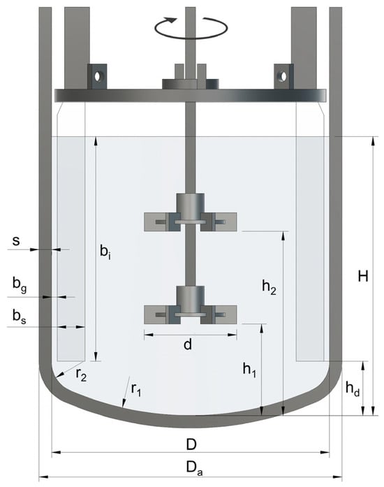
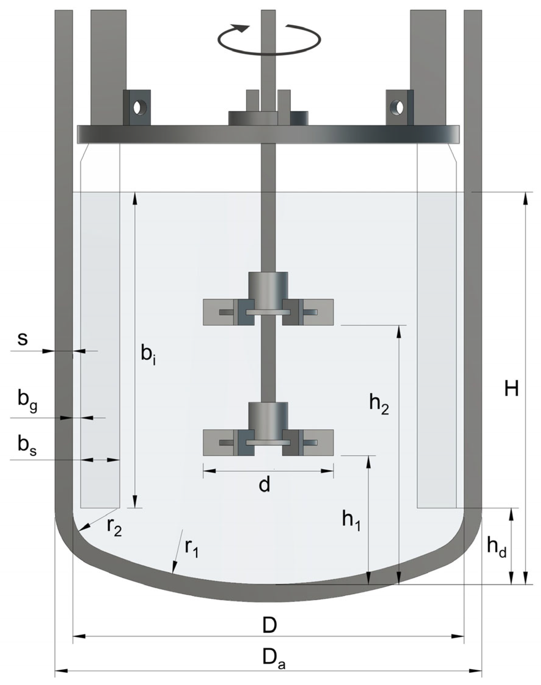
All experiments are performed in a laboratory-scale dished-bottom vessel made of acrylic glass. The vessel design and dimensions are presented in Table 1 and Figure 1.
Table 1.
Stirred-tank dimensions.
Figure 1.
Dished-bottom vessel design; parameter definitions are given in Table 1.
The filling level H is equal to the inner vessel diameter D (H/D = 1) and corresponds to a liquid volume V of 0.98 L. The dished bottom, designed according DIN 28011 [33], is milled into a solid acrylic glass block, which serves as the vessel base, while the cylindrical part consists of an acrylic glass tube. Even though this is not the standard reported in the literature [7,14,34,35], the vessel is equipped with six rectangular baffles. This design is based on prior research showing that the standard baffle setup with four rectangular baffles is not sufficient to ensure vortex-free measurements in multi-stage stirring systems under fully turbulent flow conditions [22,36,37,38]. However, the baffle dimensions presented in Table 1 are designed according to the recommendations found in the literature [7,34,39]. They are made of acrylic glass with a thickness of 5 mm and are mounted on a 3D-printed construction, which is inserted into the vessel from the top so that the distance between the lower baffle edge and the lowest point of the vessel bottom is equal to the dished bottom height hd, as illustrated in Figure 1. The 3D-printed construction is equipped with three ball bearings stabilizing the shaft, which has a diameter of 4 mm and is made of stainless steel.
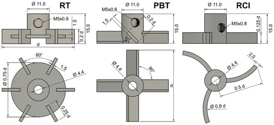
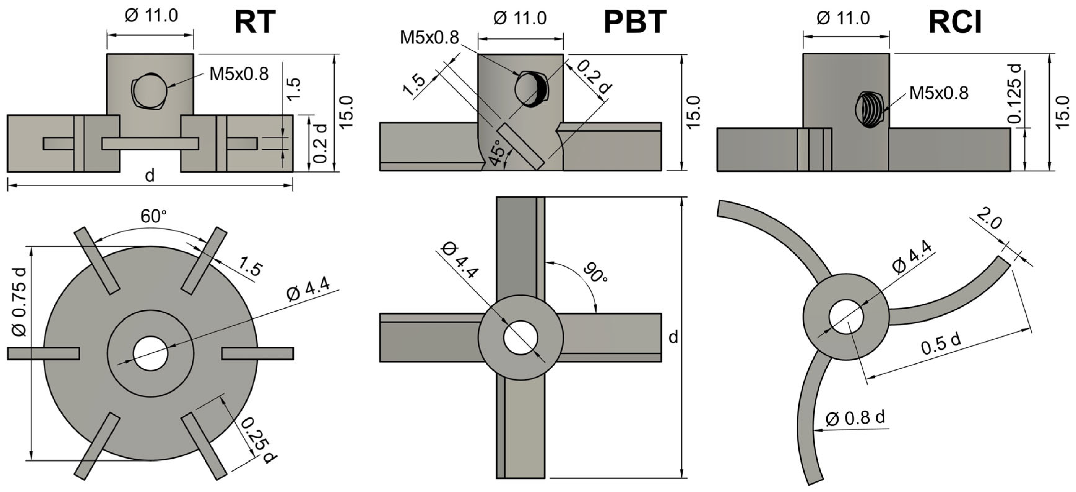
Three different stirrer geometries are investigated: the retreat curve impeller (RCI) and Rushton turbine (RT), both known as radial-flow turbines, and the pitched-blade turbine (PBT), representing a primary axial-flow turbine [14,34,40,41,42]. The impellers are designed in Autodesk Fusion 360 CAD software and are 3D-printed with an accuracy of 0.05 mm using a Form 3B+ printer (Formlabs, Somerville, MA, USA). Dimensions of the different impeller geometries are presented in Figure 2 and correspond to the recommendations of DIN 28131 [34]. All impellers have a cylindrical mount, which is adapted from Matzke et al. [22,36], and allows the stirrers to be attached to the shaft. The dimensions of the cylindrical mount, the blade thickness, and the total height are kept constant and do not change with variation in the impeller diameter d. To ensure stability and good print quality, the blade thickness is set to 1.5 mm for RT and PBT, and 2.0 mm for RCI.
Figure 2.
Dimensions of Rushton turbine (RT), pitched-blade turbine (PBT), and retreat curve impeller (RCI) depending on impeller diameter d from side and top views; diameter-independent dimensions are given in mm.
In single-impeller configurations, the impeller is installed at a height h1 of 0.33 D (this is the same height as for the lower impeller in double-stage configurations), while the upper impeller is positioned at h2 = 0.67 D. Contrary to the commonly recommended installation height of the retreat curve impeller close to the vessel bottom [34,40], uniform installation heights are applied to ensure comparability and to systematically investigate differences in flow structures between the impeller types under identical installation conditions, as comparable recommendations do not exist for multi-stage configurations. The direction of rotation is clockwise as seen from above.
2.2. Torque Measurement
Power characteristics are determined by torque measurements with deionized water. A system provided by Hottinger Brüel & Kjaer is used for data acquisition, consisting of a torque transducer of the type T22/0.5Nm and a QuantumX MX440B 4-channel amplifier. A shaft-type torque sensor is installed between the motor and the stirrer shaft with bellows couplings and is connected to the amplifier, which transmits the data to catmanEasy software (version 5.3.2.16).
As the torque is subject to slight fluctuations, 3000 data points are recorded in an interval of 30 s for each rotational speed setting. The first measurement is taken at 50 rpm. For the subsequent measurements, the rotational speed is incrementally increased in steps of 50 rpm and from 300 rpm upwards in steps of 100 rpm. To ensure that the flow conditions are stationary during data recording, the measurement is started with a delay of five minutes after increasing the rotational speed. For the following analysis, mean torque and standard deviation are determined from the 3000 data points for every rotational speed setting.
The power P is directly proportional to the measured torque M and is calculated using Equation (1):
P = 2πMn
By dividing the resulting power P by the liquid volume V, the specific-power input P/V is determined. The power number Ne and Reynolds number Re are defined as shown in Equations (2) and (3), where is the fluid density, n the rotational speed, d the impeller diameter, the dynamic viscosity, and the kinematic viscosity:
2.3. Particle Image Velocimetry
In this study, the stereoscopic particle image velocimetry (stereo-PIV) technique is applied, making it possible to resolve the three velocity components in the plane by using two cameras, which is why it is also referred to as 2D3C (two-dimension three-component) PIV [43]. We employ the PIV measurement system from Dantec Dynamics (Skovlunde, Denmark), consisting of a Nd:YAG double-pulsed laser (Litron Lasers, Warwickshire, England, DualPower 135-15, 532 nm, 135 mJ, 15 Hz), two FlowSense EO5M cameras (Dantec Dynamics, resolution 2456 × 2058 pixels, 16 Hz), and a timer box that synchronizes laser and camera triggering. Each camera is equipped with a Zeiss planar T* 1.4/50 lens.
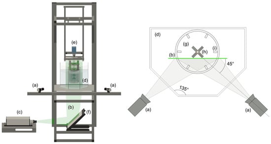
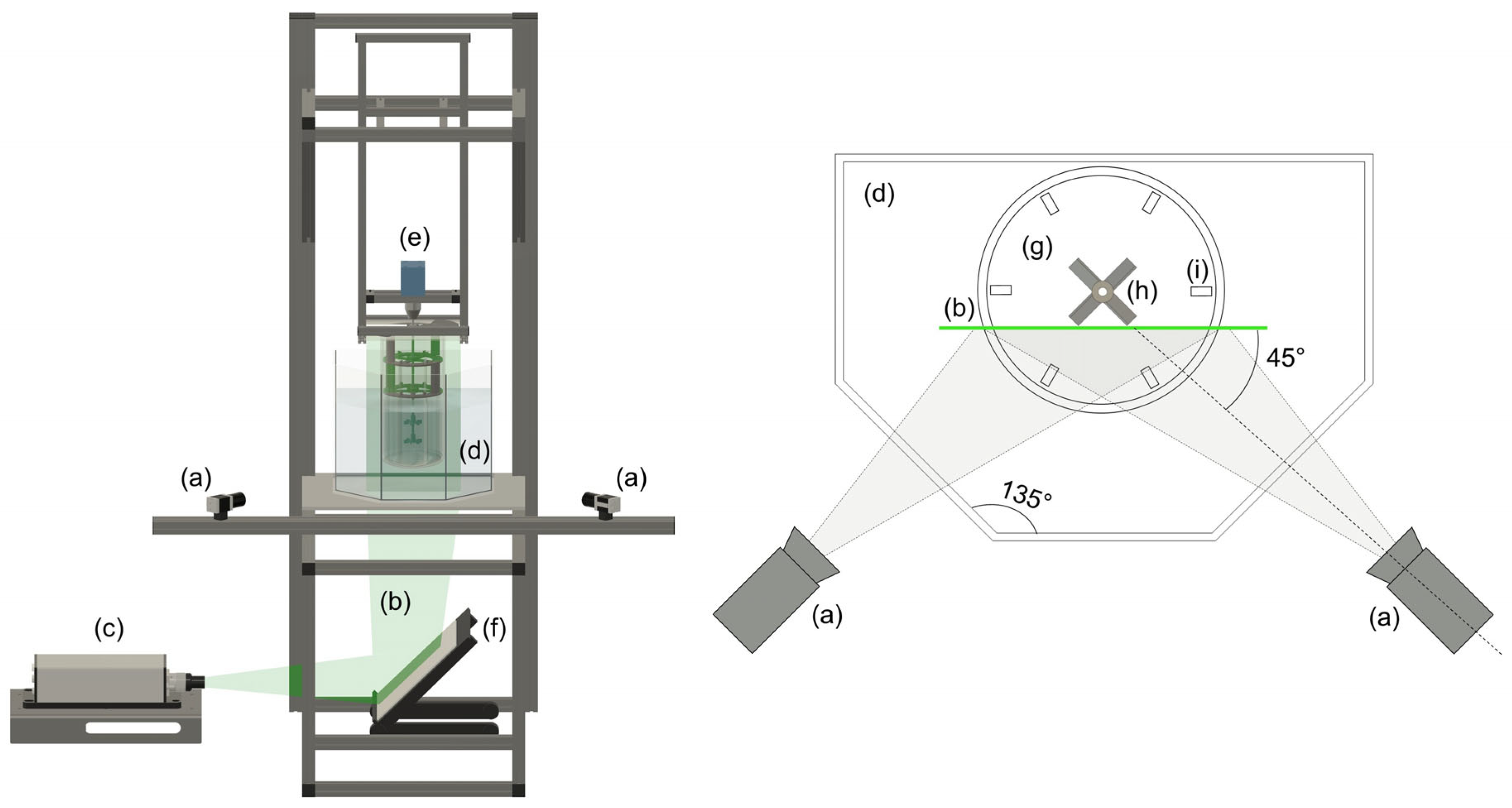
With a rectangular plate glued to the cylindrical part on the upper edge, the vessel is mounted in a specially designed construction, shown in Figure 3. This construction has already been used in several studies of stirred tanks involving laser-optical methods [15,22,23,44,45,46,47,48]. To enable the cameras to be directed towards a flat surface, the vessel is immersed into a polyhedral aquarium made of acrylic glass.
Figure 3.
Stereo-PIV setup for flow field measurements: (a) cameras, (b) laser light sheet, (c) Nd:YAG laser, (d) polyhedral acrylic glass aquarium filled with RIM fluid, (e) stirrer motor, (f) 45° mirror, (g) acrylic glass dished-bottom vessel filled with RIM fluid, (h) stirrer, (i) rectangular baffle.
In order to optimize the optical accessibility and to minimize light refraction effects during measurements caused by the curved wall, the dished bottom, and the baffles, both the vessel and the aquarium are filled with a refractive-index-matching fluid (RIM fluid). In this study, an aqueous solution of ammonium thiocyanate (62 wt%, ρ = 1135 kg/m3, ν = 1.68∙10−6 m2/s) with a refractive index of 1.492 is used, which corresponds to that of acrylic glass [32] and thus makes the edges of the vessel and baffles invisible to the cameras. This enables accurate flow field measurements even in the curved-bottom region. The RIM fluid in the stirred tank is seeded with polyamide tracer particles with a diameter of 50 µm (Dantec Dynamics, PSP-50). To minimize reflections affecting the camera sensor, a 3D-printed flexible ring with a width of 9 mm is mounted on the outer vessel wall to cover the liquid surface.
To ensure uniform image brightness for both cameras, the vessel is illuminated from below [23]. The laser sheet is formed by the light sheet optics attached to the laser head and is directed onto a 45° mirror deflecting the light sheet vertically towards the vessel, where it illuminates the tracer particles. To avoid shadows in the measuring plane, the laser sheet is positioned in front of the stirrer tips and between the baffles, as illustrated in Figure 3. The position of the laser sheet is the same for all stirrer configurations. Each camera forms an angle of 45° with the laser light sheet. With this angled camera perspective, Scheimpflug mounts are required to precisely focus the entire field of view in the object plane, which is known as the Scheimpflug condition [43,49].
Cameras and laser are externally triggered once per full impeller rotation using a remote optical sensor by Monarch Instruments (ROS-P), ensuring a consistent impeller position for each trigger. Two images are taken per trigger with a short time interval ∆t to obtain double-frame images. The time delay ∆t needs to be long enough to allow the particle movement to be detected and short enough to prevent too many particles from leaving the light sheet between the pulses [49]. For this reason, it has to be adjusted for different rotational speed settings and stirrer configurations depending on the flow velocity, which is between 0.5 and 5 ms in this study. Two hundred double-frame images are recorded for each camera.
Data acquisition, processing, and analysis are performed with DynamicStudio software (version 8.3) by Dantec Dynamics. In a pre-processing step, the background brightness of the captured images is reduced, and regions of no interest are masked. Since images are taken with an angled camera view, image dewarping is necessary. For this purpose, multi-camera calibration is performed, which allows the software to identify the exact position of the two cameras.
The displacement vectors of the double-frame images are obtained by applying a cross-correlation algorithm, which divides the images into 128 × 128 pixel interrogation areas with refinement down to 16 × 16 pixel interrogation areas and analyzes the particle movement. Based on the time delay between the double-frame images (∆t), flow velocity can be computed, resulting in two-dimensional vector images for each camera perspective. These are merged in the next step to generate 200 three-component velocity fields, which are further combined to obtain one vector statistics map for each measurement, representing the average of all 200 individual velocity fields.
The impeller rotational speeds investigated for flow field analyses are chosen to match specific Reynolds numbers, allowing for a dimensionless assessment of the flow regime. Stereo-PIV measurements are performed at Reynolds numbers of 2500, 5000, 7500, and 10,000 to cover a range of flow conditions. The resulting flow velocities v are normalized by the impeller tip speed vtip to enable an analysis that is independent of impeller speed and Reynolds number, as discussed in more detail in Section 3.2.
To allow a quantitative comparison of the flow characteristics between different impeller configurations, the mean velocity vmean/vtip as well as the relative share of low-velocity regions Av/vtip<0.05 are evaluated. The parameter Av/vtip<0.05 denotes the fraction of the measurement area in which the normalized velocity v/vtip is below 0.05, corresponding to dead-zone definitions used in flow field analyses based on numerical simulations [50,51]. In addition, the stereo-PIV technique provides access to the tangential velocity component, which is presented as the ratio of the tangential velocity to the local velocity magnitude.
2.4. Specific-Power Harmonization
As Matzke et al. [22] have already demonstrated, when combining different stirrer geometries on the same shaft, matching specific-power inputs P/V is essential in order to avoid the dominance of one impeller and thus uneven velocity distributions across the stirred tank. It was therefore proposed to correlate the impeller diameter d/D and the specific power P/V to obtain P/V-matching diameters for the different stirrer types by using linear regression functions of three data points each.
However, the power number Ne (Equation (2)), which is proportional to 1/d5, indicates a polynomial correlation between power and impeller diameter. Therefore, instead of using linear regression, data points of the correlation between d/D and P/V are approximated with polynomials in this study to investigate whether the method of Matzke et al. [22] can be further improved.
To evaluate whether this approach can achieve sufficient accuracy with reduced complexity, both fifth- and third-degree polynomials are applied. Compared to the approach of Matzke et al. [22], the number of data points for approximation is increased from three to eight. For this purpose, each of the three stirrer types is printed with eight different diameters covering the standard application range given in the literature, as presented in Table 2.
Table 2.
Standard diameter range of pitched-blade turbine (PBT), Rushton turbine (RT), and retreat curve impeller (RCI) given in the literature [34,40,41,52] and printed diameters for torque measurements and P/V harmonization.
Most of the dimensions are scaled depending on the chosen diameter d, as shown in Figure 2. The power input is determined for every diameter listed in Table 2 in a rotational speed range between 50 and 2000 rpm, as described in Section 2.2.
3. Results and Discussion
3.1. Specific-Power Harmonization
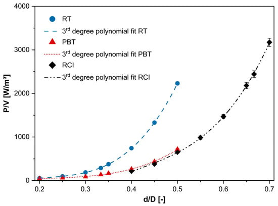
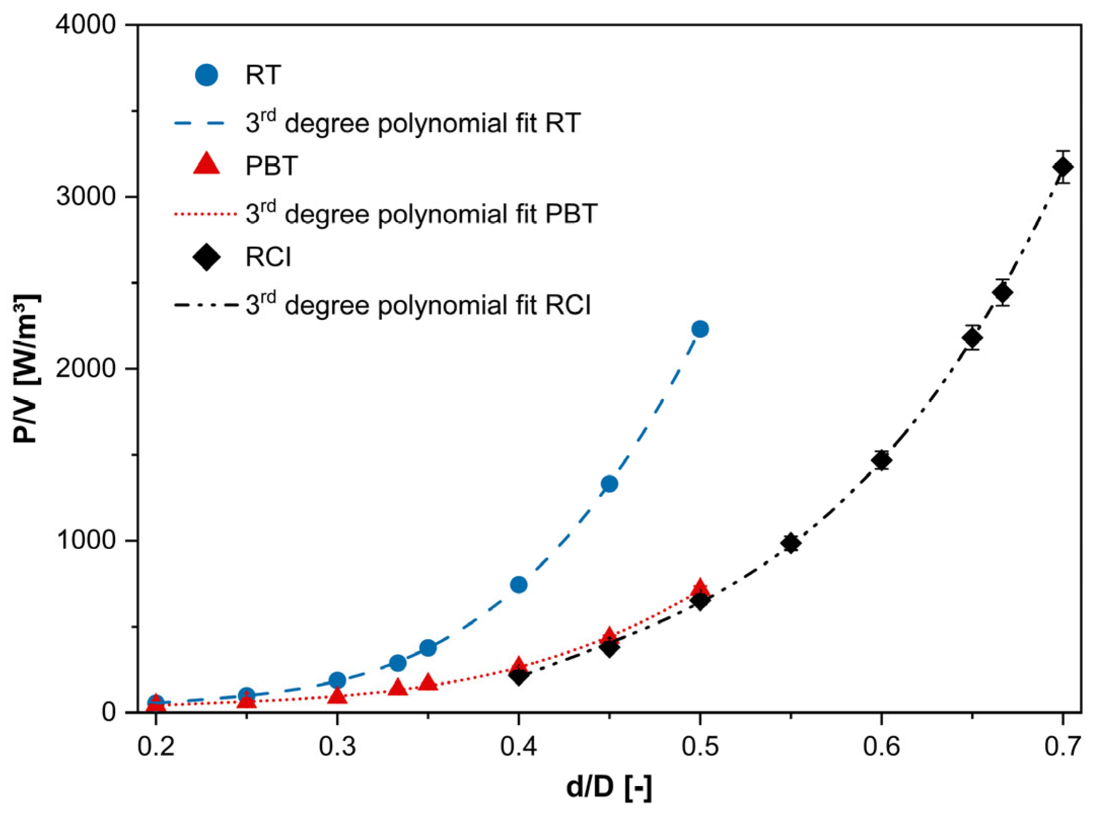
The correlations between the specific power P/V and the impeller diameter d obtained from the torque measurements are presented in Figure 4, exemplary for a rotational speed of 600 rpm. The error bars represent the standard deviations calculated from 3000 recorded data points.
Figure 4.
Specific power P/V depending on impeller diameter d/D at 600 rpm for Rushton turbine (RT), pitched-blade turbine (PBT), and retreat curve impeller (RCI); error bars plotted for all data points but not visible for RT and PBT due to their small size; dashed lines indicate approximations with third-degree polynomial.
Data is approximated with third- and fifth-degree polynomials. The base polynomial for approximating the specific power P/V as a function of the impeller-to-tank diameter ratio d/D is defined in Equation (4):
P/V(d/D) = A1(d/D)5 + A2(d/D)4 + A3(d/D)3 + A4(d/D)2 + A5(d/D) + A6
The determined coefficients A1 to A6, as well as the coefficients of determination (R2), adjusted coefficients of determination (R2adj), and the root-mean-square error (RMSE), are presented in Table 3. Since no visible differences are observed between the plots of the third- and the fifth-degree polynomials, only the third-degree polynomials are shown in Figure 4.
Table 3.
Determined polynomial coefficients A1 to A6, coefficients of determination R2, adjusted R2 (R2adj), and root-mean-square errors (RMSE) for fifth- and third-degree (deg) polynomial approximation for the specific power P/V and diameter d/D of the three impeller types (600 rpm; cf. Figure 4).
It is important to note that the presented polynomials are only meant to approximate the data within the selected diameter range and do not serve as a general mathematical description of the specific power as a function of geometry.
Nevertheless, the very high coefficients of determination obtained for all cases (R2 > 0.999, R2adj > 0.998) clearly verify the predicted polynomial correlation between specific power and impeller diameter. This high fit quality was consistently confirmed for several rotational speeds across the investigated range, indicating robust performance of the applied fitting procedure. For all cases, the RMSE values are low compared to the data range, which is approximately between 50 and 2200 W/m3 for RT and PBR, and between 210 and 3100 W/m3 for RCI. Compared to the linear regression approaches using only three data points proposed by Matzke et al. [22], who reported coefficients of determination of 0.947 and 0.945 for PBT and RT, the present method provides significant improvements in approximation accuracy and fit quality of the specific power across a broad diameter range. This is essential to ensure equal power input and prevent imbalances in the fluid flow when combining different impeller geometries.
However, while the use of fifth-degree polynomials yields slightly higher coefficients of determination and lower RMSE values, the improvement compared to third-degree polynomials is marginal. Differences in R2 and R2adj are confined to the third or fourth decimal place, and the reduction in RMSE is small relative to the overall data scale. Therefore, the use of a third-degree polynomial is considered sufficient for determining the P/V-matching diameters and allows simplification without any appreciable loss of accuracy. Using the presented polynomials, P/V-matching diameters can be determined for each impeller type. Considering only diameters between the minimum and maximum diameter measured, the possible range for finding diameters with matching P/V is between about 200 W/m3 (limited by the RCI curve) and 700 W/m3 (limited by the PBT curve).
In order to minimize the absolute difference in diameters between the three impeller types and to keep the d/D ratios for RT and PBT close to the widely used diameter of 0.33 D [4,16,40,53,54,55,56,57], the P/V-matching diameters presented in Table 4 are chosen.
Table 4.
Selected P/V-matching impeller diameters for Rushton turbine (RT), pitched-blade turbine (PBT), and retreat curve impeller (RCI) determined using third-degree polynomials.
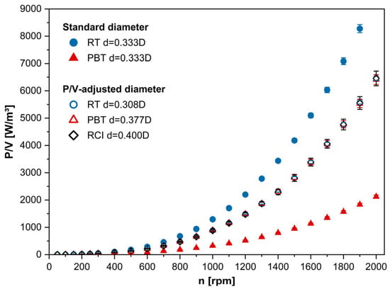
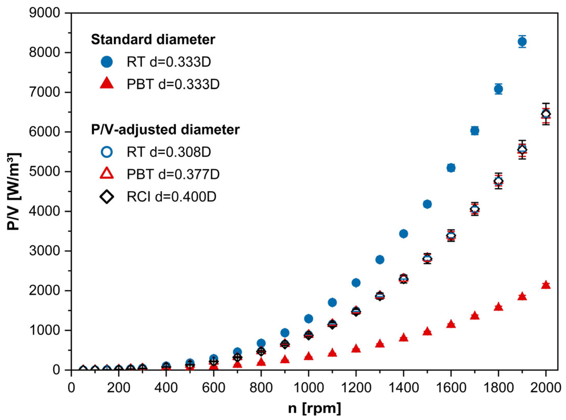
The three impeller types are 3D-printed with these selected diameters, and torque is measured for validation. The results are presented in Figure 5, showing the correlation between P/V and the rotational speed before the adjustment with a 0.33 D standard diameter for RT and PBT and after the adjustment with the diameters listed in Table 4.
Figure 5.
Correlation between specific power P/V and rotational speed n of the three impeller types with standard and adjusted diameters for P/V harmonization.
Since the chosen P/V-matching diameter for the RCI of 0.40 D was already part of the measurements used to determine the polynomial fit, no additional torque measurement is required, and only this dataset is displayed for RCI. The graph clearly confirms the success of the specific-power harmonization, as the data points of the P/V values determined for the three impeller types with adjusted diameters overlap over the entire rotational speed range. With turbulent flow conditions, the maximum deviations in specific power measured for the three impeller types with adjusted diameters are less than 3%, which proves the model’s accuracy.
The presented approach using polynomial fits is readily applicable to other multi-stage systems involving different impeller types. Specific-power harmonization should be considered essential for mixed impeller systems to prevent impeller dominance.
The impellers with the P/V-adjusted diameters presented in Table 4 are used for all subsequent PIV measurements in this study to maintain equal power inputs.
3.2. Flow Field Analysis
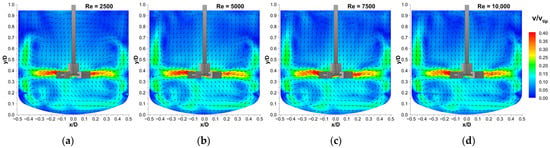
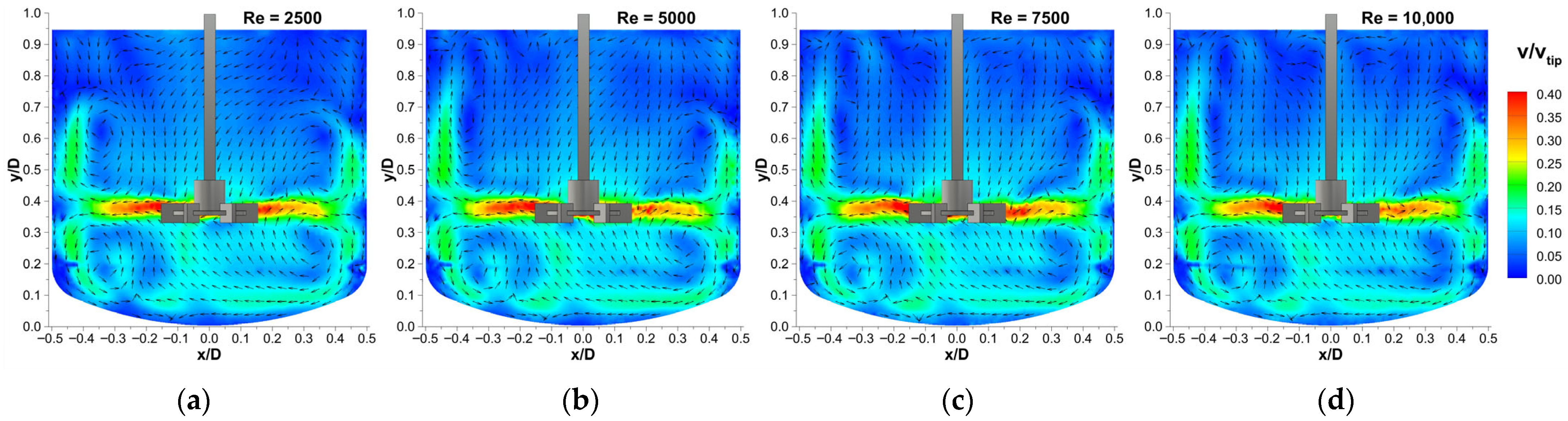
Flow velocities of all investigated configurations are measured at Reynolds numbers of 2500, 5000, 7500, and 10,000. However, when normalizing the determined flow velocity v with the impeller tip speed vtip, only minor differences between the flow fields remain across the investigated Reynolds numbers, as demonstrated for a single Rushton turbine in Figure 6.
Figure 6.
Normalized velocity plots v/vtip of a single Rushton turbine at different Reynolds number settings with h1 = 0.33 D. (a) Re = 2500, (b) Re = 5000, (c) Re = 7500, (d) Re = 10,000.
This dimensionless velocity plot is a common approach for visualizing flow fields in stirred tanks [6,21,22,23,24,25,54] and allows comparisons between different impeller configurations independent of stirring speed and Reynolds number. Consequently, the influence of Re can be neglected in the following, and only one representative flow field at Re = 10,000 is presented for each impeller configuration.
In some flow fields, a faint horizontal line can be observed at a vessel height of approximately 0.2 D, where the flow velocity appears to be lower than in the surrounding region. This effect is caused by the weld seam at the junction between the cylindrical part of the vessel and the vessel bottom. Due to the difficulty in detecting particles behind this seam, the measured velocity in this region appears lower than it actually is. However, these minor artifacts have no impact on the quality of velocity determination in the rest of the vessel and do not affect the evaluation of the flow characteristics, as their extent is negligible.
Since the liquid surface is covered by a ring mounted on the outer vessel wall, as described in Section 2.3, PIV measurements provide velocity data only up to a vessel height of 0.95 D.
3.2.1. Single-Impeller Configurations
Since the impeller types covered in this study are traditionally used only in a single configuration at H/D = 1, the measured flow fields of single RT, PBT, and RCI are presented in Figure 7 (first row, from left to right) as a reference for evaluating the effects of dual impellers subsequently. To ensure comparability, the P/V-matching diameters determined for the mixed impeller combinations in Table 4 are also used for PIV measurements of the single configurations.
Figure 7.
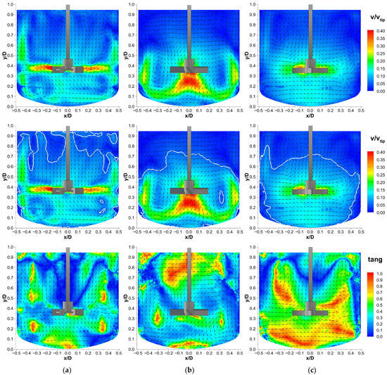
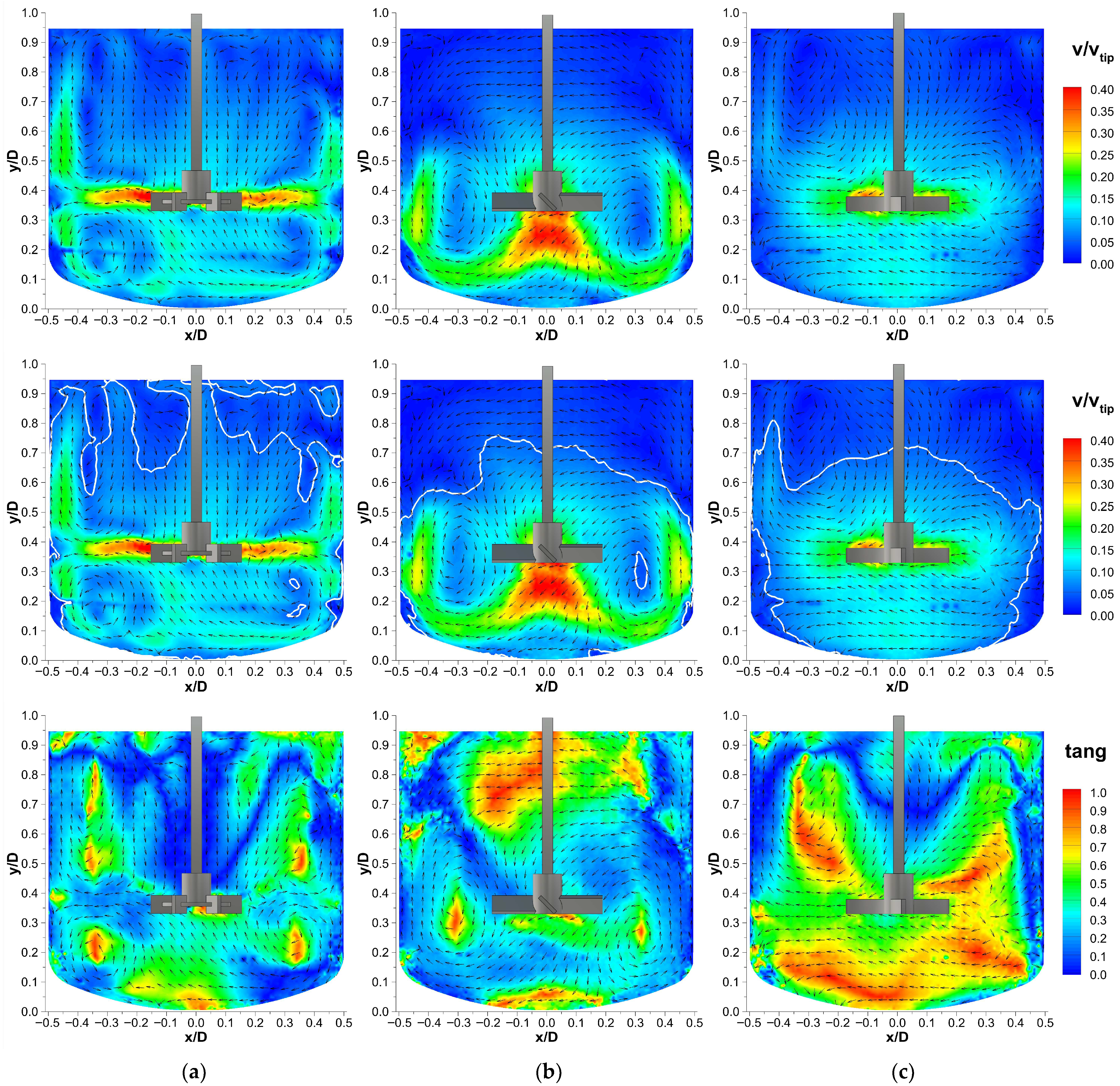
Flow characteristics of a single (a) Rushton turbine (RT), (b) pitched-blade turbine (PBT), and (c) retreat curve impeller (RCI) with P/V-matching impeller diameters of d/DRT = 0.308, d/DPBT = 0.377, and d/DRCI = 0.400; an impeller installation height of h1 = 0.33 D; and Re = 10,000. (First row): velocity fields (v/vtip); (second row): corresponding contour maps with white lines marking low-velocity regions with v/vtip < 0.05; (third row): local fractions of tangential velocity component (tang), defined as the ratio of tangential velocity to the local velocity magnitude.
The determination of low-velocity regions is visualized in the second row of Figure 7, where the white contours highlight regions with normalized velocities v/vtip below 0.05. The tangential flow, expressed as the ratio of the tangential velocity to the local velocity magnitude, is shown in the third row. The determined mean velocity vmean/vtip, the fraction of low-velocity regions Av/vtip<0.05, and the mean tangential fraction tangmean are presented in Table 5.
Table 5.
Flow characteristics of single-impeller configurations: mean normalized flow velocity vmean/vtip, fraction of low-velocity areas Av/vtip<0.05, and mean tangential fraction of local velocity magnitude tangmean.
The obtained flow patterns clearly reveal the different performance of the three impeller types, although they have the same specific power. The Rushton turbine (Figure 7a) creates the expected radial profile known from the literature. The flat vertical blades accelerate the fluid from the tip of the impeller horizontally towards the vessel wall, where it is divided into an upper and a lower vortex. The lower vortices follow the curved shape of the dished bottom, resulting in comparatively high velocities in the bottom area. The upper vortices extend to around 80% of the vessel height and induce increased velocities along the vessel wall, making the Rushton turbine the impeller with the fewest dead zones. However, the flow velocity remains low in the upper quarter of the liquid volume.
The flow field of the pitched-blade turbine (Figure 7b) exhibits the characteristic behavior of an axial-flow impeller. The flow velocity and vector field indicate a high velocity flow directly below the impeller, which is directed downwards by the angled blades and deflected at the vessel bottom, forming axial vortices recirculating upwards along the vessel walls. A region of low velocity can be observed at the vessel bottom beneath the impeller, where the flow splits into axial vortices. The vortices only reach approximately 60% of the tank height, resulting in large areas of near-zero velocities in the upper third of the vessel, which account for 33.9% of the measurement area.
Although the retreat curve impeller (Figure 7c) is commonly classified as a radial-flow turbine in the literature [34,40,41,42], it does not show a typical radial profile. The velocity vectors are directed from the impeller tips towards the vessel wall, but radial vortices are barely developed. High velocities are observed only locally around the impeller, with a dominant tangential flow component. While the Rushton turbine exhibits a mean tangential fraction of 29%, this parameter is markedly higher at 46% for the retreat curve impeller, which can significantly limit mixing performance due to strong fluid rotation without axial and radial cross-mixing. Flow velocities at the vessel walls, in the upper third of the liquid volume, and in the region where the curved bottom merges into the cylindrical part of the vessel are limited to values close to zero, covering 35.8% of the measurement area, which is the largest fraction among the three impellers. This limited pumping effect is most likely due to the comparatively low blade height and number, as well as the curved blade design, promoting a dominant tangential flow around the impeller.
The flow fields presented for single RT, PBT, and especially RCI clearly demonstrate that, although single impellers are standard and recommended for stirred tanks with H/D = 1, considerable regions, especially in the upper part of the vessel, remain insufficiently circulated due to low flow velocities. This leads to local overconcentration, incomplete or side reactions, overheating, and prolonged processing times, which can strongly limit product quality and severely compromise process safety and efficiency.
To investigate whether these velocities can be increased, the flow fields of mixed and identical double-stage impeller configurations are examined in the next step, where a second stirrer is positioned in the upper third of the vessel at 0.67 D.
3.2.2. Identical Impeller Combinations
Since flow fields of all possible double-stage combinations of the Rushton turbine, pitched-blade turbine, and retreat curve impeller are investigated, configurations with identical impellers are included as well. P/V adjustment is not required when combining the same impeller types with equivalent dimensions, as they inherently achieve the same specific-power input. Nevertheless, to ensure comparability across all stirrer configurations, the diameters determined for the mixed combinations in Table 4 are also applied to the identical impeller combinations.
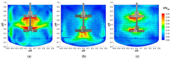
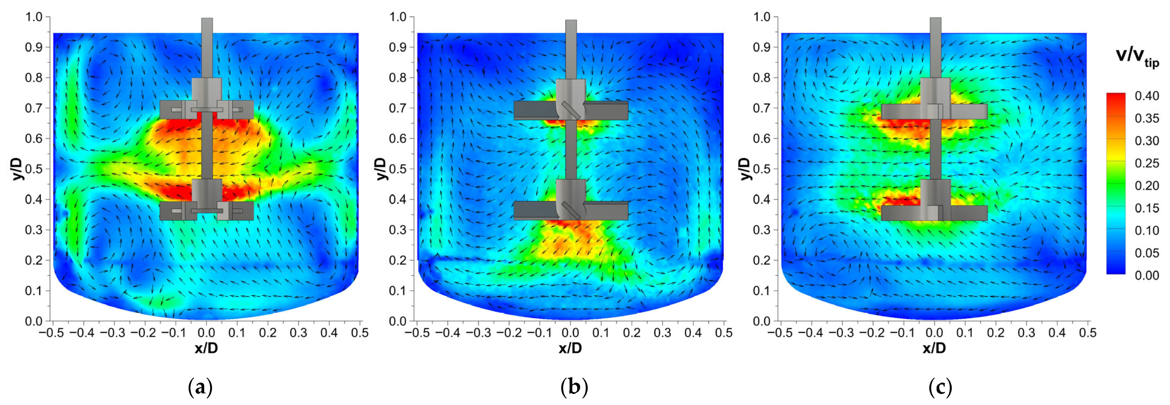
Figure 8 presents the flow fields of the identical double-stage configurations for the Rushton turbine, pitched-blade turbine, and retreat curve impeller.
Figure 8.
Velocity fields v/vtip of (a) dual Rushton turbine (RT), (b) dual pitched-blade turbine (PBT), and (c) dual retreat curve impeller (RCI) with P/V-matching diameters of d/DRT = 0.308, d/DPBT = 0.377, and d/DRCI = 0.400 at Re = 10,000; impeller installation heights of h1 = 0.33 D and h2 = 0.67 D.
The mean velocity vmean/vtip, the fraction of low-velocity regions Av/vtip<0.05, and the mean tangential fraction tangmean are determined in the same manner as for the single-impeller configurations and are presented in Table 6.
Table 6.
Flow characteristics of double-impeller configurations: mean normalized flow velocity vmean/vtip, fraction of low-velocity areas Av/vtip<0.05, and mean tangential fraction of local velocity magnitude tangmean.
In the case of the double RT (Figure 8a), a merging radial-flow pattern is observed, consistent with findings reported for similar setups in flat-bottom stirred tanks [16,22,28,29,58]. Instead of forming a horizontal radial outflow towards the vessel wall with separate radial vortices, the flow is deflected upwards from the lower impeller and downwards from the upper impeller, resulting in a high-velocity zone between the two Rushton turbines. The combined flow is directed towards the vessel wall and divides into an upper and a lower circulation vortex at 50% of the vessel height. Although the lower vortex extends to the vessel bottom, the local flow velocity in this region is reduced compared to the single-RT configuration. However, the fraction of low-velocity areas is reduced from 16.3% to 5.1% when using a double instead of a single Rushton turbine, and the mean normalized velocity is increased from 0.098 to 0.133.
In the double-PBT configuration (Figure 8b), a distinct axial-flow profile is generated only by the lower impeller. Compared to the single-stage configuration, the overall vortex velocity is reduced, while the recirculation zone extends further upwards. The flow is directed axially up to approximately 80% of the vessel height for the dual PBT, and in the single-PBT setup, recirculation already begins at around 40% of the vessel height. The upper PBT fails to establish a dominant axial flow, likely due to interference with the opposing flow generated by the lower impeller, resulting in a disruptive interaction. The inward flow from the lower vortex is counteracted by the outward flow induced by the upper impeller, which reduces the axial-flow intensity in the region between 40% and 60% of the tank height. Flow velocities are only slightly increased in the upper half of the liquid volume, while noticeably reduced in the lower half compared to the single-stage configuration, resulting in a slight reduction in the mean velocity compared to the single configuration. These findings suggest that increasing the blade angle of the upper impeller or varying the pumping directions in a double-PBT setup may help to better feed the lower stage and to prevent disruptive interactions between the partial flows. This should be investigated in future studies and offers further potential to positively influence the overall flow characteristics. Despite the slightly reduced overall velocity compared to the single PBT, the fraction of dead zones is reduced from 33.9% to 18.4% in the double-PBT setup. However, the dead zone fraction remains notably higher than for the double Rushton turbine and retreat curve impeller configurations.
With two RCIs mounted on the same shaft (Figure 8c), the flow around each impeller remains largely independent, with turbulence limited to the immediate vicinity of each impeller. Interaction between the stages is minimal and the overall flow field resembles a parallel combination of two single-RCI profiles. As in the single-RCI configuration, no radial vortices are formed, leading to a decrease in velocity towards the vessel wall and bottom. Nevertheless, compared to the single-stage RCI, higher velocities are observed in the upper half of the vessel, leading to a higher mean velocity and a reduced fraction of low-velocity regions, indicating improved circulation due to the presence of the second impeller.
3.2.3. Mixed Impeller Combinations
Following the analysis of identical impeller combinations, flow fields of the mixed impeller configurations are investigated in the next step. To avoid unbalanced flow patterns caused by the dominance of the impeller with the higher power input, P/V harmonization is applied by using the adjusted diameters determined in Table 4. For the mixed configurations combining impellers with different diameters on the same shaft, the diameter of the larger impeller serves as the basis for the calculation of tip speed and Reynolds number.
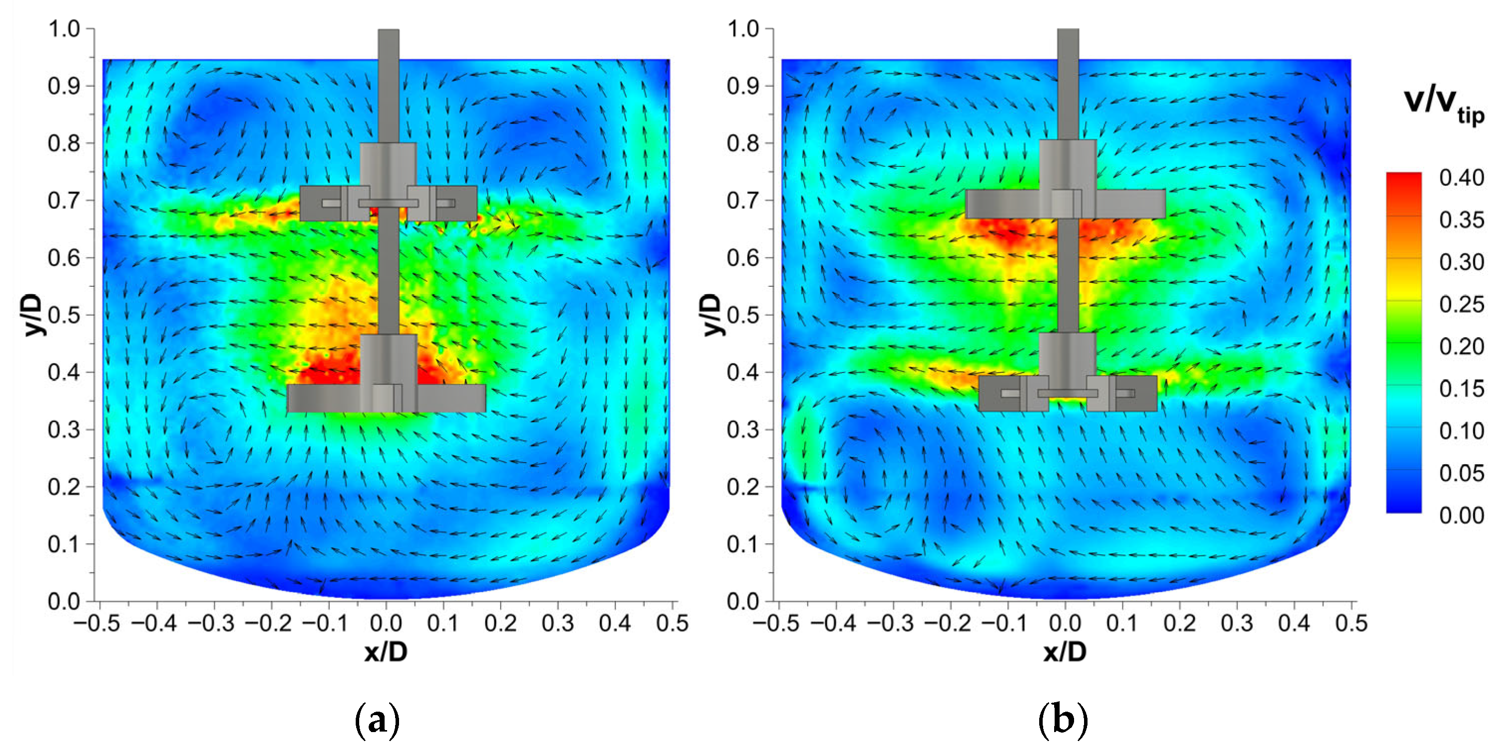
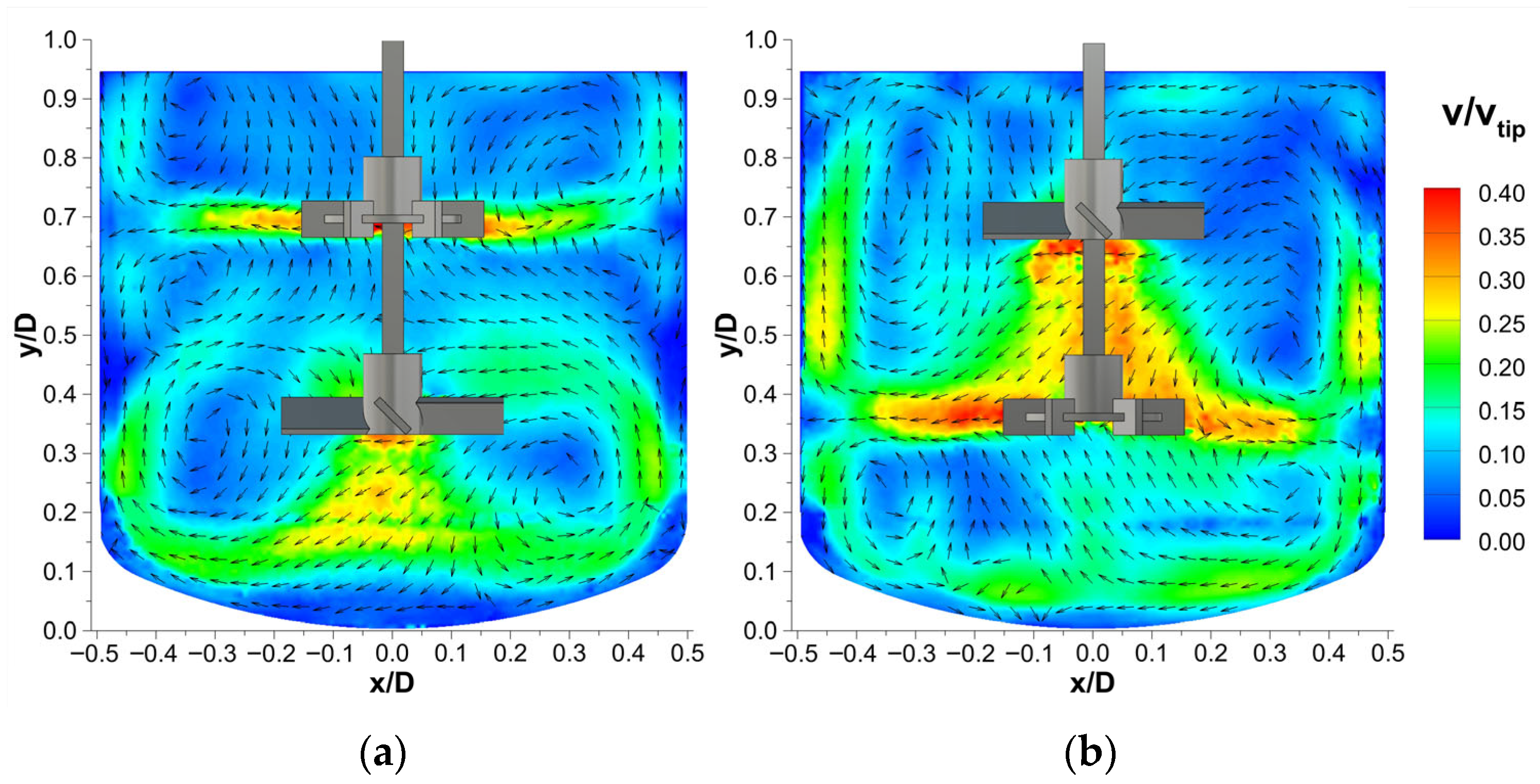
Figure 9 presents the vector maps of the two possible mixed double-stage combinations of the Rushton turbine and retreat curve impeller. The mean velocity vmean/vtip, the fraction of low-velocity regions Av/vtip<0.05, and the mean tangential fraction tangmean are presented in Table 7.
Figure 9.
Velocity fields v/vtip of mixed Rushton turbine (RT) and retreat curve impeller (RCI) combinations with P/V-matching impeller diameters of d/DRT = 0.308 and d/DRCI = 0.400 at Re = 10,000: (a) RCI as lower impeller with h1,RCI = 0.33 D and h2,RT = 0.67 D; (b) RT as lower impeller with h1,RT = 0.33 D and h2,RCI = 0.67 D.
Table 7.
Flow characteristics of mixed Rushton turbine (RT) and retreat curve impeller (RCI) configurations: mean normalized flow velocity vmean/vtip, fraction of low-velocity areas Av/vtip<0.05, and mean tangential fraction of local velocity magnitude tangmean.
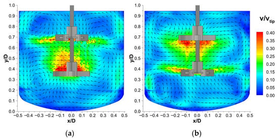
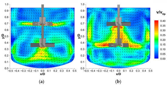
The flow fields of both configurations are nearly identical in shape, but reversed when the impeller positions are inverted. In both setups, the retreat curve impeller primarily generates a localized flow around its immediate vicinity, which extends either upwards or downwards in the direction of the Rushton turbine, creating a zone of high velocity between the two impellers. The Rushton turbine generates the typical radial flow towards the vessel wall. Compared to the single-RT configuration, the radial vortices are slightly extended and reach beyond the RCI. While flow velocity in the upper third of the vessel is higher than in the single-stage setups, it remains low near the vessel bottom, particularly when the RCI is positioned as the lower impeller (Figure 9a).
When the RCI is mounted in the upper position (Figure 9b), vortex formation and surface aeration occur at lower stirring speeds than in configurations with the RT as the upper impeller, and exhibit a higher mean tangential fraction. Mean velocities of both arrangements are similar to the double-RCI configuration, but with lower fractions of low-velocity areas, representing a significant improvement in flow velocity distribution compared to the single RT and RCI.
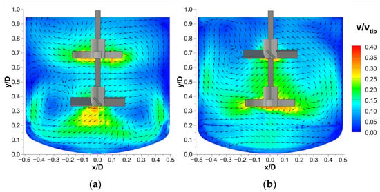
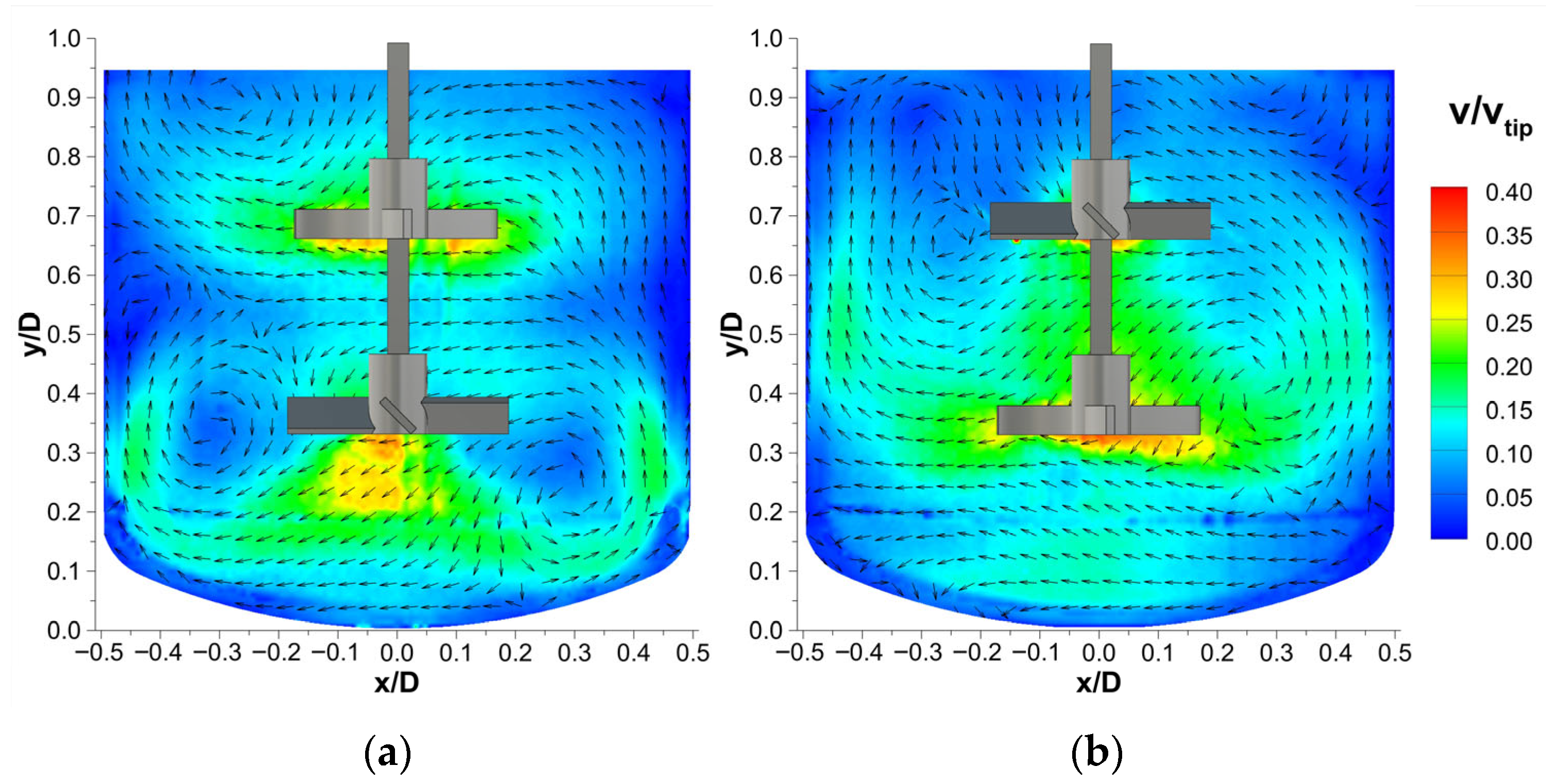
In contrast to the RCI and RT combinations, flow fields of the mixed configurations consisting of a retreat curve impeller and a pitched-blade turbine, as presented in Figure 10, exhibit markedly different flow patterns depending on the impeller arrangement. When the PBT is mounted below the RCI (Figure 10a), two independent flow structures are formed. The flow fields remain separated and closely resemble those observed in the respective single-impeller configurations, with low velocities between the two impellers. This characteristic is unfavorable for uniform mixing and short mixing times, as interaction and transfer between the circulation zones are limited.
Figure 10.
Velocity fields v/vtip of mixed pitched-blade turbine (PBT) and retreat curve impeller (RCI) combinations with P/V-matching impeller diameters of d/DPBT = 0.377 and d/DRCI = 0.400 at Re = 10,000: (a) PBT as lower impeller with h1,PBT = 0.33 D and h2,RCI = 0.67 D; (b) RCI as lower impeller with h1,RCI = 0.33 D and h2,PBT = 0.67 D.
When the PBT is mounted above the RCI (Figure 10b), a merging flow pattern is observed. The PBT creates a strong downward flow, which intensifies the flow of the RCI. The velocity beneath the impeller is increased, and enlarged vortices are generated beside the RCI, which are not present in the single configuration. These effects are therefore solely caused by the addition of the axial-flow PBT and enhance the circulation in the lower 70% of the vessel. However, flow velocities at the edges of the vessel bottom as well as above and beside the upper impeller remain low, as the PBT primarily directs the liquid downwards into the RCI flow and the joint vortex does not reach the upper quarter of the vessel.
Despite the different shapes of the flow patterns, the characteristics presented in Table 8 do not show significant differences between the two PBT-RCI arrangements. However, the mean velocities are increased compared to the single-stage impeller, and the fraction of dead zones is considerably lower, although these effects are slightly less pronounced than for the RCI-RT configurations (Table 7).
Table 8.
Flow characteristics of mixed pitched-blade turbine (PBT) and retreat curve impeller (RCI) configurations: mean normalized flow velocity vmean/vtip, fraction of low-velocity areas Av/vtip<0.05, and mean tangential fraction of local velocity magnitude tangmean.
Vector maps of the mixed combinations of the Rushton turbine and pitched-blade turbine are shown in Figure 11, and reveal flow interactions similar to those observed in the mixed PBT-RCI configurations, but with significantly stronger radial flow generated by the RT. This observation is supported by the characteristics presented in Table 9, showing the lowest fractions of the tangential flow component among all investigated double-stage impellers. A relative decrease in the tangential flow can substantially improve mixing performance, since fluid rotation is reduced and axial and radial mixing are enhanced. Although dedicated mixing time studies are required to draw definite conclusions, the observed flow characteristics already indicate promising potential for improved mixing performance.
Figure 11.
Velocity fields v/vtip of mixed Rushton turbine (RT) and pitched-blade turbine (PBT) combinations with P/V-matching diameters of d/DRT = 0.308 and d/DPBT = 0.377 at Re = 10,000: (a) PBT as lower impeller with h1,PBT = 0.33 D and h2,RT = 0.67 D; (b) RT as lower impeller with h1,RT = 0.33 D and h2,PBT = 0.67 D.
Table 9.
Flow characteristics of mixed pitched-blade turbine (PBT) and Rushton turbine (RT) configurations: mean normalized flow velocity vmean/vtip, fraction of low-velocity areas Av/vtip<0.05, and mean tangential fraction of local velocity magnitude tangmean.
When the PBT is mounted below the RT (Figure 11a), the two impellers create a separated flow with axial vortices in the lower half and radial vortices in the upper half of the vessel. Compared to the PBT-RCI configuration with the RCI on top (Figure 10a), the flow velocity between the two impellers and around the upper impeller is increased due to the stronger radial pumping behavior of the RT, which also results in a higher mean velocity. This configuration may be advantageous for gassing applications, as it forms two sepa rate circulation zones with limited interaction, which potentially extends the bubble residence time and enhances mass transfer.
In the reverse arrangement with the PBT mounted on top (Figure 11b), a strong synergistic effect is observed. The axial component generated by the angled blades of the PBT reinforces the radial pumping action of the RT, leading to a high-velocity zone between the two impellers as well as increased wall and bottom velocities compared to a single RT. A distinct axial vortex is not developed, as the PBT pumps directly into the RT, creating an amplified flow structure characterized by strong circulation and high fluid velocities in all areas of the tank. This configuration exhibits the highest mean velocity and the lowest dead-zone fraction among all investigated impeller configurations, representing a significant improvement over the single-impeller setups and indicating high potential for a wide range of mixing tasks, especially for homogenization and enhanced heat transfer through the vessel wall.
4. Conclusions
The present study experimentally investigated the flow behavior of single- and double-stage configurations of a Rushton turbine, a pitched-blade turbine, and a retreat curve impeller in a dished-bottom vessel with a standard geometry ratio of H/D = 1, and contributes to resolving the significant lack of systematic and detailed flow data. Stereo-PIV measurements, combined with refractive-index matching, allowed the capture of all three velocity components and to overcome optical challenges. An optimized and experimentally validated model for specific-power harmonization of mixed multi-stage impellers was presented, which significantly improves the accuracy compared to existing approaches and successfully prevents imbalanced flow fields. The presented method of specific-power matching is readily applicable to other multi-stage systems and should be considered essential for the design and scale-up of systems involving different impeller geometries. In addition to detailed flow field analyses, this study compared the dead zone fraction, mean velocity, and mean tangential fraction to provide quantitative evidence.
Vector maps of the single-impeller configurations revealed extensive regions of insufficient circulation. For the first time, the retreat curve impeller was included in a comprehensive experimental flow field study in both single- and double-impeller configurations. It was found to exhibit only a weak radial pumping effect and a dominating tangential flow, promoting vortex formation and limiting axial and radial cross-mixing.
Double-stage impellers significantly improved flow characteristics across all configurations, resulting in increased velocities and markedly reduced dead zones. The mixed PBT-RT setups demonstrated especially promising flow behavior with high velocities throughout the entire vessel. With the PBT above the RT, intensified merging radial flow and high wall velocities were observed, showing the highest mean velocity and lowest dead zone fraction across all configurations. These characteristics make the PBT-RT configuration particularly suitable for homogenization and heat transfer applications.
Overall, this study clearly demonstrates the great potential of double-stage stirrers, especially in vessels with H/D = 1. In particular, the mixed impeller configurations lead to alternative superior flow characteristics not achievable with single impellers. The intensified circulation leads to higher overall productivity and substantial process advantages, including a reduction in local overconcentration, prevention of incomplete and side reactions, avoidance of overheating, shorter processing times, and increased product yield and quality. This enables the optimization of mixing processes and contributes to safer, more sustainable, and more energy-, resource-, and cost-efficient operations [59]. The presented approach of adding a second stirrer is applicable to new and existing plants, as modifications are limited to the impeller configuration, opening the door to a wide range of industrial applications.
To build on the findings of this study, mixing-time investigations of the presented setups using laser-induced fluorescence are already planned. Future research should also focus on studies of gas holdup and heat transfer efficiency to further quantify the benefits outlined. Flow field analysis of double-stage impellers operating in multiphase systems is also of great interest and highly relevant for industrial applications. However, alternative measurement approaches will be necessary to overcome challenges arising with high bubble concentrations or opaque media [60,61]. Despite stereo-PIV measurements allowing the capture of all three velocity components, they are limited to a two-dimensional measurement plane. Volumetric PIV could therefore provide more detailed three-dimensional flow information. In addition, extending the investigations to include more impeller types, installation heights, fill levels, and vessel diameters is essential to derive comprehensive design and scale-up recommendations for multi-stage stirrer systems.
Author Contributions
Conceptualization, L.K., M.U. and H.J.S.; methodology, L.K. and H.J.S.; validation, L.K., C.Z. and H.J.S.; formal analysis, L.K., A.G. and H.J.S.; investigation, L.K. and A.G.; resources, H.J.S.; data curation, L.K. and H.J.S.; writing—original draft preparation, L.K.; writing—review and editing, L.K., C.Z., M.U. and H.J.S.; visualization, L.K., A.G. and C.Z.; supervision, M.U. and H.J.S.; project administration, M.U. and H.J.S. All authors have read and agreed to the published version of the manuscript.
Funding
This project was supported by the German Federal Ministry for Economic Affairs and Energy (Bundesministerium für Wirtschaft und Energie) within the framework of the program for the promotion of Industrial Collective Research (Industrielle Gemeinschaftsforschung, IGF) on the basis of a decision by the German Bundestag (22782 N/1).
Data Availability Statement
The data presented in this study are available from the corresponding author upon reasonable request.
Acknowledgments
The authors acknowledge the financial, administrative, and technical support provided by the internal open access publication fund of the Niederrhein University of Applied Sciences, as well as the Institute for Coatings and Surface Chemistry (ILOC).
Conflicts of Interest
The authors declare no conflicts of interest.
Abbreviations
The following abbreviations are used in this manuscript:
| A1–6 | polynomial coefficient |
| Av/vtip<0.05 | fraction of measurement area where v/vtip is below 0.05 [-] |
| bg | gap between baffle and vessel wall [m] |
| bi | baffle immersion depth [m] |
| bs | baffle width [m] |
| D | inner vessel diameter [m] |
| Da | outer vessel diameter [m] |
| d | impeller diameter [m] |
| H | liquid fill level [m] |
| hd | dished bottom height [m] |
| h1/2 | installation height impellers 1 and 2 [m] |
| LDA | laser Doppler anemometry |
| M | torque [Nm] |
| n | rotational speed [s−1] |
| Ne | power number [-] |
| P | power [W] |
| PBT | pitched-blade turbine |
| PIV | particle image velocimetry |
| P/V | specific-power input [W m−3] |
| R2 | coefficient of determination [-] |
| R2adj | adjusted coefficient of determination [-] |
| RCI | retreat curve impeller |
| Re | impeller Reynolds number [-] |
| RIM | refractive-index matching |
| RMSE | Root-mean-square error |
| RT | Rushton Turbine |
| r1 | curvature radius bottom [m] |
| r2 | curvature radius junction [m] |
| s | wall thickness [m] |
| tang | fraction of tangential flow component relative to local velocity magnitude [-] |
| tangmean | mean tangential fraction of local velocity magnitude [-] |
| ∆t | time between pulses [s] |
| V | liquid volume [m3] |
| v | flow velocity [m s−1] |
| vmean | mean flow velocity [m s−1] |
| vtip | impeller tip speed [m s−1] |
| ρ | density [kg m−3] |
| μ | dynamic viscosity [Pa s] |
| ν | kinematic viscosity [m2 s−1] |
References
- You, S.T.; Raman, A.A.A.; Shah, R.S.S.R.E.; Mohamad Nor, M.I. Multiple-impeller stirred vessel studies. Rev. Chem. Eng. 2014, 30, 323–336. [Google Scholar] [CrossRef] [Scilit]
- Tatterson, G.B.; Brodkey, R.S.; Calabrese, R.V. Move Mixing Technology Into the 21st Century. Chem. Eng. Prog. 1991, 87, 45–48. [Google Scholar]
- Gogate, P.R.; Beenackers, A.A.; Pandit, A.B. Multiple-impeller systems with a special emphasis on bioreactors: A critical review. Biochem. Eng. J. 2000, 6, 109–144. [Google Scholar] [CrossRef] [Scilit] [PubMed]
- Magelli, F.; Montante, G.; Pinelli, D.; Paglianti, A. Mixing time in high aspect ratio vessels stirred with multiple impellers. Chem. Eng. Sci. 2013, 101, 712–720. [Google Scholar] [CrossRef] [Scilit]
- Xie, M.; Xia, J.; Zhou, Z.; Zhou, G.; Chu, J.; Zhuang, Y.; Zhang, S.; Noorman, H. Power consumption, local and average volumetric mass transfer coefficient in multiple-impeller stirred bioreactors for xanthan gum solutions. Chem. Eng. Sci. 2014, 106, 144–156. [Google Scholar] [CrossRef] [Scilit]
- Posadas-Navarro, D.; Palacios, C.; Blancas-Cabrera, A.; Trujillo-Roldán, M.A.; Salinas-Vázquez, M.; Ascanio, G. Flow Patterns of Multiple Axial-Radial Impellers for Potential Use in Aerated Stirred Tanks. Chem. Eng. Technol. 2022, 45, 860–867. [Google Scholar] [CrossRef] [Scilit]
- Liepe, F.; Sperling, R.; Jembere, S. Rührwerke: Theoretische Grundlagen, Auslegung und Bewertung, 1st ed.; Eigenverl: Köthen, Germany, 1998. [Google Scholar]
- Armenante, P.M.; Chou, C.-C. Velocity profiles in a baffled vessel with single or double pitched-blade turbines. AIChE J. 1996, 42, 42–54. [Google Scholar] [CrossRef] [Scilit]
- Karcz, J. Studies of local heat transfer in a gas–liquid system agitated by double disc turbines in a slender vessel. Chem. Eng. J. 1999, 72, 217–227. [Google Scholar] [CrossRef] [Scilit]
- Puthli, M.S.; Rathod, V.K.; Pandit, A.B. Gas–liquid mass transfer studies with triple impeller system on a laboratory scale bioreactor. Biochem. Eng. J. 2005, 23, 25–30. [Google Scholar] [CrossRef] [Scilit]
- Karimi, A.; Golbabaei, F.; Mehrinia, M.; Mohammad, K.; Neghab, M.; Nikpey, A.; Pourmand, M. Investigation of Gas Hold up and Power Consumption in a Stirred Tank Bioreactor Using Single and Dual Impeller Configurations. Int. J. Occup. Hyg. 2012, 5, 109–116. [Google Scholar]
- Bernauer, S.; Eibl, P.; Witz, C.; Khinast, J.; Hardiman, T. Analyzing the effect of using axial impellers in large-scale bioreactors. Biotechnol. Bioeng. 2022, 119, 2494–2504. [Google Scholar] [CrossRef] [Scilit] [PubMed]
- Woziwodzki, S. Mixing of viscous Newtonian fluids in a vessel equipped with steady and unsteady rotating dual-turbine impellers. Chem. Eng. Res. Des. 2014, 92, 435–446. [Google Scholar] [CrossRef] [Scilit]
- Zlokarnik, M. Rührtechnik: Theorie und Praxis; Springer: Berlin, Germany, 1999. [Google Scholar]
- Matzke, M.; Ulbricht, M.; Schultz, H.J. Investigation of the Mixing Time Distribution and Connected Flow Fields in Two-Stage Stirred Vessels. Processes 2024, 12, 132. [Google Scholar] [CrossRef] [Scilit]
- Rutherford, K.; Lee, K.C.; Mahmoudi, S.M.S.; Yianneskis, M. Hydrodynamic characteristics of dual Rushton impeller stirred vessels. AIChE J. 1996, 42, 332–346. [Google Scholar] [CrossRef] [Scilit]
- Li, Z.; Song, G.; Bao, Y.; Gao, Z. Stereo-PIV experiments and large eddy simulations of flow fields in stirred tanks with Rushton and curved-Blade turbines. AIChE J. 2013, 59, 3986–4003. [Google Scholar] [CrossRef] [Scilit]
- Li, Z.; Bao, Y.; Gao, Z. PIV experiments and large eddy simulations of single-loop flow fields in Rushton turbine stirred tanks. Chem. Eng. Sci. 2011, 66, 1219–1231. [Google Scholar] [CrossRef] [Scilit]
- De Mitri, A.G.; Amaral, R.d.L.; de Moura, H.L.; Ayala, J.S.; Nunhez, J.R.; de Castilho, G.J. Tilted PIV: A novel approach for estimating the turbulent kinetic energy in stirred tanks. Measurement 2023, 217, 113112. [Google Scholar] [CrossRef] [Scilit]
- Taghavi, M.; Moghaddas, J. Using PLIF/PIV techniques to investigate the reactive mixing in stirred tank reactors with Rushton and pitched blade turbines. Chem. Eng. Res. Des. 2019, 151, 190–206. [Google Scholar] [CrossRef] [Scilit]
- Alberini, F.; Liu, L.; Stitt, E.H.; Simmons, M. Comparison between 3-D-PTV and 2-D-PIV for determination of hydrodynamics of complex fluids in a stirred vessel. Chem. Eng. Sci. 2017, 171, 189–203. [Google Scholar] [CrossRef] [Scilit]
- Matzke, M.; Ranft, E.; Dominkovic, L.; Ulbricht, M.; Schultz, H.J. Flow Field Investigations of Two-Stage Stirrer Configurations Combining Axially and Radially Conveying Turbines. Chem. Ing. Tech. 2023, 95, 1592–1602. [Google Scholar] [CrossRef] [Scilit]
- Jährling, K.; Schultz, H.J. Flow Fields in Stirred Vessels Depending on Different Internal Heat Exchangers and Vessel Bottoms. Chem. Ing. Tech. 2019, 91, 1281–1292. [Google Scholar] [CrossRef] [Scilit]
- Unadkat, H.; Rielly, C.D.; Hargrave, G.K.; Nagy, Z.K. Application of fluorescent PIV and digital image analysis to measure turbulence properties of solid–liquid stirred suspensions. Chem. Eng. Res. Des. 2009, 87, 573–586. [Google Scholar] [CrossRef] [Scilit]
- Busciglio, A.; Montante, G.; Paglianti, A. Flow field and homogenization time assessment in continuously-fed stirred tanks. Chem. Eng. Res. Des. 2015, 102, 42–56. [Google Scholar] [CrossRef] [Scilit]
- Wang, C.; Xu, Y.; Wu, Y.; An, Z. PIV investigation of the flow features of double and single 45° up-pumping pitched blade turbines in a square tank. Can. J. Chem. Eng. 2018, 96, 788–799. [Google Scholar] [CrossRef] [Scilit]
- Li, Z.; Hu, M.; Bao, Y.; Gao, Z. Particle Image Velocimetry Experiments and Large Eddy Simulations of Merging Flow Characteristics in Dual Rushton Turbine Stirred Tanks. Ind. Eng. Chem. Res. 2012, 51, 2438–2450. [Google Scholar] [CrossRef] [Scilit]
- Liu, X.; Bao, Y.; Li, Z.; Gao, Z.; Smith, J.M. Particle Image Velocimetry Study of Turbulence Characteristics in a Vessel Agitated by a Dual Rushton Impeller. Chin. J. Chem. Eng. 2008, 16, 700–708. [Google Scholar] [CrossRef] [Scilit]
- Pan, C.; Min, J.; Liu, X.; Gao, Z. Investigation of Fluid Flow in a Dual Rushton Impeller Stirred Tank Using Particle Image Velocimetry. Chin. J. Chem. Eng. 2008, 16, 693–699. [Google Scholar] [CrossRef] [Scilit]
- Ebrahimi, M.; Tamer, M.; Villegas, R.M.; Chiappetta, A.; Ein-Mozaffari, F. Application of CFD to Analyze the Hydrodynamic Behaviour of a Bioreactor with a Double Impeller. Processes 2019, 7, 694. [Google Scholar] [CrossRef] [Scilit]
- Chen, M.; Wang, J.; Zhao, S.; Xu, C.; Feng, L. Optimization of Dual-Impeller Configurations in a Gas–Liquid Stirred Tank Based on Computational Fluid Dynamics and Multiobjective Evolutionary Algorithm. Ind. Eng. Chem. Res. 2016, 55, 9054–9063. [Google Scholar] [CrossRef] [Scilit]
- Borrero-Echeverry, D.; Morrison, B.C.A. Aqueous ammonium thiocyanate solutions as refractive index-matching fluids with low density and viscosity. Exp. Fluids 2016, 57, 123. [Google Scholar] [CrossRef] [Scilit]
- DIN 28011:2012-06; Gewölbte Böden; Klöpperform. Deutsches Institut für Normung: Berlin, Germany, 2012. [CrossRef] [Scilit]
- DIN 28131:1992-09; Rührer und Stromstörer für Rührbehälter; Formen, Benennungen und Hauptmaße. Deutsches Institut für Normung: Berlin, Germany, 1992. [CrossRef] [Scilit]
- Harnby, N. Mixing in the Process Industries, 2nd ed.; Butterworth-Heinemann: Oxford, UK, 1997. [Google Scholar]
- Matzke, M.; Behrens, C.; Jongebloed, N.; Steins, D.; Ulbricht, M.; Schultz, H.J. Investigation and Visualization of Flow Fields in Stirred Tank Reactors Using a Fluorescence Tracer Method. Chem. Ing. Tech. 2022, 94, 1131–1140. [Google Scholar] [CrossRef] [Scilit]
- Lenters, L.; Matzke, M.; Ranft, E.; Schultz, H.J. Dependencies of the vortex formation in multistage stirring systems. Chem. Ing. Tech. 2022, 94, 1359. [Google Scholar] [CrossRef] [Scilit]
- Heyter, A.; Wollny, S. Einfluss verschiedener Stromstörerausführungen auf die Bewehrung eines mehrstufigen Rührbehälters. Chem. Ing. Tech. 2017, 89, 416–423. [Google Scholar] [CrossRef] [Scilit]
- Reschetilowski, W. Handbuch Chemische Reaktoren: Grundlagen und Anwendungen der Chemischen Reaktionstechnik; Springer: Berlin, Germany, 2020. [Google Scholar]
- Kraume, M. Mischen und Rühren: Grundlagen und Moderne Verfahren; Wiley-VCH: Weinheim, Germany, 2003. [Google Scholar]
- Ekato. EKATO: The Book, 3rd ed.; EKATO: Schopfheim, Germany, 2012. [Google Scholar]
- Kresta, S.M.; Etchells, A.W.; Dickey, D.S.; Atiemo-Obeng, V.A.; North American Mixing Forum (Eds.) Advances in Industrial Mixing: A Companion to the Handbook of Industrial Mixing; Wiley: Hoboken, NJ, USA, 2016. [Google Scholar]
- Cavazzini, G. The Particle Image Velocimetry—Characteristics, Limits and Possible Applications; InTech: Rijeka, Croatia, 2012. [Google Scholar]
- Jährling, K.; Wolinski, S.; Stefan, A.; Helle, H.; Bliem, V.; Ulbricht, M.; Schultz, H.J. Particle Image Velocimetry Compared to CFD Simulation of Stirred Vessels with Helical Coils. Chem. Ing. Tech. 2017, 89, 401–408. [Google Scholar] [CrossRef] [Scilit]
- Kögel, L.; Zube, C.; Matzke, M.; Ulbricht, M.; Schultz, H.J. Flow Field Visualization of Multi-Stage Stirred Tank Reactors with Different Impeller Types and Clearances Using Stereo-PIV. In Proceedings of the 14th European Congress of Chemical Engineering and 7th European Congress of Applied Biotechnology, Berlin, Germany, 17–21 September 2023. [Google Scholar] [CrossRef]
- Zube, C.; Kögel, L.; Matzke, M.; Ulbricht, M.; Schultz, H.J. Investigation of mixing time distribution of multi-stage impellers in stirred tank reactors using Planar Laser Induced Fluorescence. In Proceedings of the 14th European Congress of Chemical Engineering and 7th European Congress of Applied Biotechnology, Berlin, Germany, 17–21 September 2023. [Google Scholar] [CrossRef]
- Kögel, L.; Lenters, L.; Aljeratli, H.; Tao, S.; Sunder, M.; Schultz, H.J. Identifying Optimization Potential in a Batch Process for the Production of Detergents and Cleaning Products. In Proceedings of the Jahrestreffen der Dechema/VDI-Fachgruppe Mischvorgänge, Hamburg, Germany, 19–21 March 2025. [Google Scholar] [CrossRef]
- Kögel, L.; Gieseking, A.; Zierberg, C.; Ulbricht, M.; Schultz, H.J. Visualization and Comparison of Flow Fields in Single-and Double-Stage Stirred Tanks with Dished Bottom. In Proceedings of the Jahrestreffen der Dechema/VDI-Fachgruppe Mischvorgänge, Hamburg, Germany, 19–21 March 2025. [Google Scholar] [CrossRef]
- Raffel, M.; Willert, C.; Scarano, F.; Kähler, C.; Wereley, S.; Kompenhans, J. Particle Image Velocimetry: A Practical Guide; Springer: Berlin/Heidelberg, Germany, 2018. [Google Scholar]
- Dabiri, S.; Sappl, J.; Kumar, P.; Meister, M.; Rauch, W. On the effect of the inlet configuration for anaerobic digester mixing. Bioprocess Biosyst. Eng. 2021, 44, 2455–2468. [Google Scholar] [CrossRef] [Scilit] [PubMed]
- Bridgeman, J. Computational fluid dynamics modelling of sewage sludge mixing in an anaerobic digester. Adv. Eng. Softw. 2012, 44, 54–62. [Google Scholar] [CrossRef] [Scilit]
- Weiss, S. Verfahrenstechnische Berechnungsmethoden: Stoffvereinigen in Fluiden Phasen; VCH: Weinheim, Germany, 1988. [Google Scholar]
- Devi, T.T.; Kumar, B. CFD Simulation of Flow Patterns in Dual Impeller Stirred Tank. Int. J. Model. Simul. 2013, 33, 117–125. [Google Scholar] [CrossRef] [Scilit]
- Sharp, K.V.; Adrian, R.J. PIV study of small-scale flow structure around a Rushton turbine. AIChE J. 2001, 47, 766–778. [Google Scholar] [CrossRef] [Scilit]
- Micale, G.; Brucato, A.; Grisafi, F.; Ciofalo, M. Prediction of flow fields in a dual-impeller stirred vessel. AIChE J. 1999, 45, 445–464. [Google Scholar] [CrossRef] [Scilit]
- Khan, F.R.; Rielly, C.D.; Brown, D. Angle-resolved stereo-PIV measurements close to a down-pumping pitched-blade turbine. Chem. Eng. Sci. 2006, 61, 2799–2806. [Google Scholar] [CrossRef] [Scilit]
- Liné, A.; Gabelle, J.-C.; Morchain, J.; Anne-Archard, D.; Augier, F. On POD analysis of PIV measurements applied to mixing in a stirred vessel with a shear thinning fluid. Chem. Eng. Res. Des. 2013, 91, 2073–2083. [Google Scholar] [CrossRef] [Scilit]
- Mahmoudi, S.M.; Yianneskis, M. The Variation of Flow Pattern and Mixing Time with Impeller Spacing in Stirred Vessels with Two Rushton Impellers. In Fluid Mechanics of Mixing; Moreau, R., King, R., Eds.; Springer: Dordrecht, The Netherlands, 1992; pp. 11–18. [Google Scholar]
- Stankiewicz, A.I.; Moulijn, J.A. Process Intensification: Transforming Chemical Engineering. Chem. Eng. Prog. 2000, 96, 22–34. [Google Scholar]
- Ge, M.; Sun, C.; Zhang, X.; Coutier-Delgosha, O.; Zhang, G. Synchrotron X-ray based particle image velocimetry to measure multiphase streamflow and densitometry. Radiat. Phys. Chem. 2022, 200, 110395. [Google Scholar] [CrossRef] [Scilit]
- Neogi, A.; Mohanta, H.K.; Sande, P.C. Particle image velocimetry investigations on multiphase flow in fluidized beds: A review. Flow Meas. Instrum. 2023, 89, 102309. [Google Scholar] [CrossRef] [Scilit]

Disclaimer/Publisher’s Note: The statements, opinions and data contained in all publications are solely those of the individual author(s) and contributor(s) and not of MDPI and/or the editor(s). MDPI and/or the editor(s) disclaim responsibility for any injury to people or property resulting from any ideas, methods, instructions or products referred to in the content. |
© 2026 by the authors. Licensee MDPI, Basel, Switzerland. This article is an open access article distributed under the terms and conditions of the Creative Commons Attribution (CC BY) license.