


Abstract
We demonstrate a high-energy, single-crystal KTP optical parametric oscillator directly pumped by an Nd:YAG laser at 1064 nm and compare its performance with that of a conventional master-oscillator power-amplifier system consisting of one OPO and four OPA stages. The high-energy OPO generates signal pulse energies of up to 90 mJ, whereas the MOPA system reaches 116 mJ. At a signal wavelength of 2005 nm, the measured signal and corresponding idler pulse durations are approximately 7 ns. The signal wavelength of the high-energy OPO is tunable from 1.90 to 2.17 µm, while the corresponding idler wavelength covers the range from 2.10 to 2.40 µm. The experimental results obtained with the high-energy OPO are in good agreement with numerical simulations performed using SNLO. Both systems exhibit comparable beam-propagation factors, with M2 values of approximately 10.
1. Introduction
Tunable infrared laser sources have a variety of important applications in vibration/rotation spectroscopy [1]. They allow the non-intrusive in situ detection of substances on surfaces or gases [2]. This plays a particularly important role in absorption spectroscopy needed in many pharmaceutical and medical applications [3]. Strong 2.0 µm radiation is needed to pump optical parametric oscillators to generate lasers in the wavelength regime of 3–5 µm and 8–12 µm [4,5]. A DFG (Difference Frequency Generation) process of two IR beams at slightly different wavelengths [6] allows the generation of THz radiation and can extend the tuning range further.
Several high-energy laser systems based on Ho- and Tm-doped gain media have been developed for direct operation near 2 µm [7]. For the specific wavelength, a maximal energy of 128 mJ/pulse at 10 Hz with a relatively long pulse duration of 160 ns has been realized by Masaki Yumoto et al. [8]. Helge Fonnum et al. [9] used a Tm:fiber laser to pump a Ho:YLF oscillator and reached 550 mJ laser output with a repetition rate of 1 Hz at 2 μm. Continuous-wave operation for a side-pumped Tm, Ho:YAG allows an output of 87.7 W [10], and for a longitudinally pumped Tm:YAG configuration, 115 W [11]. Tunable continuous-wave holmium lasers can be realized with an output of 30 W in the regime of 2 μm [12]. High-power OPO systems operating at 2.1 µm have been developed by Yuchun Liu et al. [13]. They achieved a total pulse energy of 162 mJ for the combined signal and idler beams, with the energy distributed nearly equally between them. Lars Behnke et al. [14] demonstrated an OPO/OPA system pumped with 2 J pulses at 1064 nm and achieved a combined signal-and-idler output energy of 800 mJ at 2.09 μm and 2.167 μm. However, these studies focused on operation near a fixed wavelength and did not experimentally demonstrate broad wavelength tuning. Many applications, such as absorption spectroscopy and laser pumping, require laser radiation with very precise wavelengths. Consequently, it is essential to have the capability to tune the wavelength of the 2 µm laser source. The most common method is to use an optical parametric oscillator (OPO) pumped by a commercially available laser source. OPOs operate on the principle of parametric amplification, producing two photons known as the signal and idler [15]. These photons have lower energy than the pump photons that interact with the nonlinear crystal within a resonator. Various materials for the crystal have been used in an OPO to generate infrared radiation (periodically poled magnesium oxide-doped lithium niobate (PPMgLN) [16], potassium titanyl phosphate (KTP) [17,18,19,20], and periodically poled rubidium KTP (ppRbKTP) [21]. Particularly for OPOs operating with nanosecond pulse durations, potassium titanyl phosphate (KTP) is often used. Closely related potassium titanyl arsenate (KTA) crystals have also been used in high-energy nanosecond OPOs pumped at 1064 nm, including high-repetition-rate systems producing signal pulse energies exceeding 100 mJ [22]. When pumped with 1064 nm radiation from a YAG laser, KTP efficiently generates signal and idler photons in the range nearby 2 µm [20]. Signal and Idler can be amplified with an optical parametric amplifier (OPA) to the desired pulse energy. This system of OPO and OPA is commonly called Master Oscillator/Power Amplifier or MOPA [23].
In this work, we demonstrate a directly Nd:YAG-pumped, single-crystal KTP OPO that combines signal pulse energies of up to 90 mJ with experimentally demonstrated broad wavelength tunability. The signal wavelength is tunable from approximately 1.90 to 2.17 µm, while the corresponding idler wavelength covers approximately 2.10 to 2.40 µm. To the best of our knowledge, this is the first directly Nd:YAG-pumped, single-crystal KTP OPO in the 2 µm spectral region to combine this level of signal pulse energy with such broad experimentally demonstrated wavelength tunability. For comparison, we also constructed a MOPA system consisting of one OPO and four OPA stages, similar to the configuration reported by Nordseth et al. [20].
2. Experimental Setup
The OPO is pumped with an Nd:YAG laser (Powerlite 8010, Continuum, Santa Clara, CA, USA) emitting at 1064 nm. The maximum available energy is 1.2 J per pulse with a repetition rate of 10 Hz and a pulse duration of 10 ns. The pump laser has a beam diameter (at 1/e2 of the maximum) of 9 mm. We measured an M2 of 2.5 using the standard method [24] provided by the International Organization for Standardization (ISO). A λ/2 plate and a polarizing cube are placed in front of the OPO to ensure a P-polarization for the pump and allow the adjustment of pulse energy.
The OPO consists of a KTP (KTiOPO4) crystal with a 10 × 10 mm2 aperture and a length of 16 mm along the propagation direction. The length was chosen as a practical compromise between nonlinear interaction length, spatial walk-off, optical damage considerations, available crystal aperture, and cost.
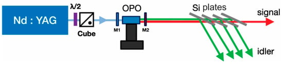
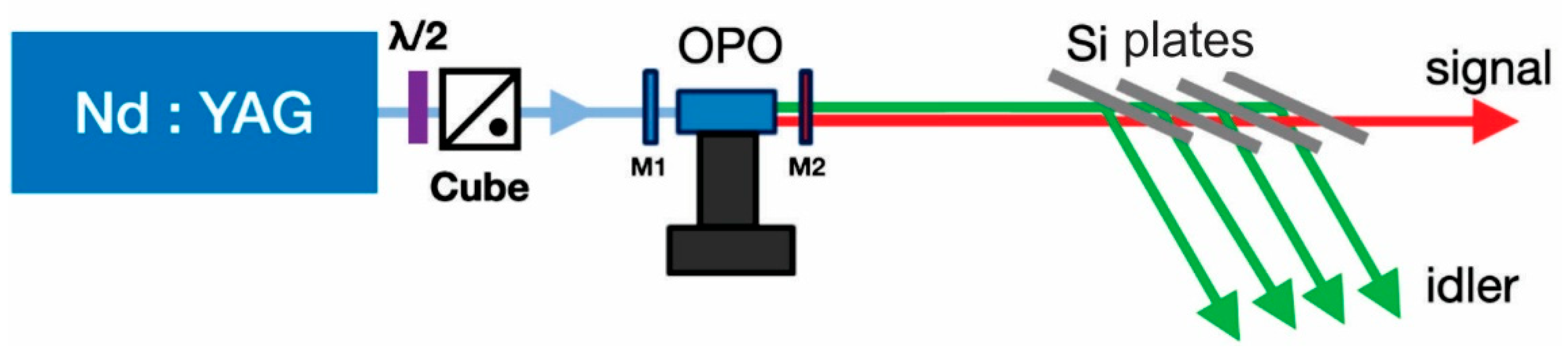
The crystal with a cut angle of θ = 53.6° (ϕ = 0°) is placed inside a cavity between two plane mirrors (M1 and M2 in Figure 1). The crystal can be rotated inside the cavity to change the signal and idler wavelengths. In addition to the idler and the signal frequencies, we can also detect the sum frequency of signal + pump (670 nm–730 nm) as well as idler and pump (690 nm–755 nm) for all rotational angles we have used [25,26]. This allows us to indirectly measure the wavelengths of the signal and idler with a fiber spectrometer from Ocean Optics USB2000 (Ocean Optics, Inc., Dunedin, FL, USA). The wavelengths of the signal and idler beams can be calculated with:
where λs and λi are the signal and idler wavelengths, respectively, λs+p is the measured wavelength of the sum-frequency signal generated by the signal and pump waves, and λi+p is the corresponding wavelength generated by the idler and pump waves.
Figure 1.
Experimental setup used for the high-energy OPO. A combination of a λ/2 plate and a polarization cube is used to change the input intensity. A set of 4 Si plates is used to separate the signal from the idler.
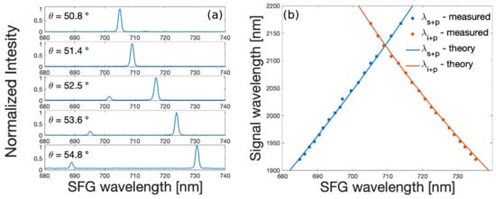
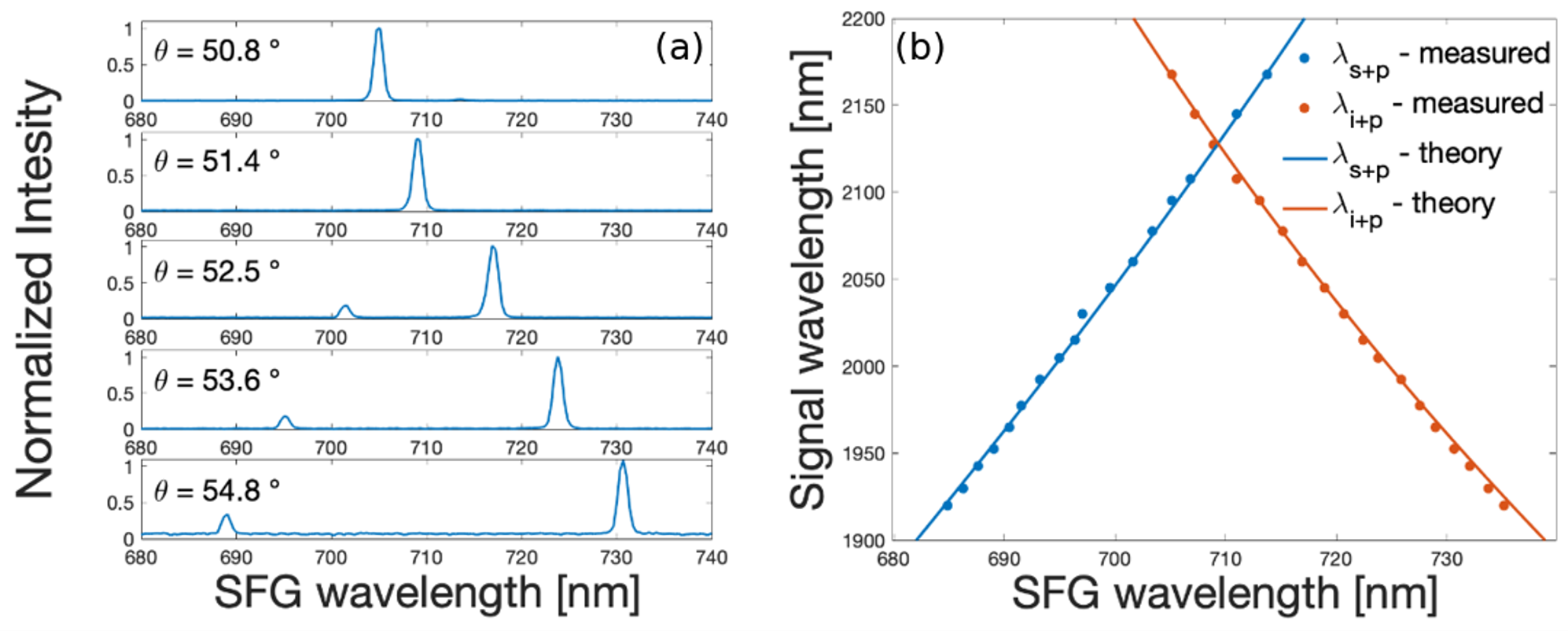
The result of this calculation can be seen in Figure 2. In Figure 2a, we show the measured wavelength for different phase-matching angles. (θ = 54.8° corresponds to λs = 1952.5 nm, θ = 53.6° corresponds to λs = 2005 nm, θ = 52.5° corresponds to λs = 2060 nm, θ = 51.4° corresponds to λs = 2127.5 nm, and θ = 50.8° corresponds to λs = 2167.5 nm). In Figure 2b, we show the wavelength of the signal and idler as a function of the wavelength of the sum of the idler + pump and signal + pump. We have verified this method with a precise direct wavelength measurement where we use a Criss-Cross Czerny–Turner monochromator (McPherson model 208) with an IR-sensitive photodiode. The KTP produces a signal of 2.005 µm and an idler of 2.267 µm with the pump laser at normal incidence. The measured signal and idler pulse durations were approximately 7 ns at this operating point, shorter than the 10 ns pump pulse. This pulse shortening is consistent with the temporal build-up of the OPO, for which oscillation occurs predominantly when the instantaneous pump intensity is above threshold. The cavity mirrors were made with a high damage threshold [27] SiO2:HfO2 coating. HfO2/SiO2 dielectric coatings are known to provide a high resistance to laser-induced damage, and an additional SiO2 protective layer can further improve their damage performance [28,29,30]. We experimentally verified this behavior for the cavity mirrors used in the present system. The mirrors withstood pump pulse energies of up to 1.2 J at 1064 nm for a 9 mm beam diameter and a repetition rate of 10 Hz. In comparison, Ta2O5-based coatings tested under similar conditions exhibited substantially lower damage resistance and were not usable for the setup. The reflectivity for the pump signal is 20% at the entrance mirror and 95% at the output coupler (Table 1). The signal and the idler reflectivities are 98% and 91% for the entrance mirror, 40% for the signal, and 93% for the idler at the output mirror. We also apply an SiO2:HfO2 anti-reflection coating on the KTP crystal to optimize the transmission for the pump, the signal, and the idler. The crystal has an average transmission better than 98% from 1950 nm to 2350 nm. The beam parameter (M2) is 10 for the idler and the signal. The degradation of the beam quality compared with the pump beam (M2 ≈ 2.5) is mainly attributed to the large Fresnel number of the OPO cavity resulting from the large pump beam diameter. A high-Fresnel-number cavity supports a larger number of transverse modes and, therefore, provides only weak spatial mode discrimination [31,32]. In addition, spatial walk-off and the nonuniform transverse parametric gain can further deteriorate the spatial profile of the generated signal and idler beams. Since the OPO is not externally seeded, the signal builds up from parametric fluorescence, and its transverse mode structure is, therefore, determined by the cavity and the spatial gain distribution rather than by the beam quality of an injected seed.
Figure 2.
On the left side (a) are typical spectra in the visible measured at the output of the OPO. On the right side (b) is the conversion between easy-to-measure SFG wavelengths (signal + pump) and (idler + pump) and the signal and pump wavelengths. (θ = 54.80 corresponds to λ = 1952 nm, θ = 53.60 corresponds to 2005 nm, θ = 52.50 corresponds to λ = 2060 nm, θ = 51.40 corresponds to λ = 2127.5 nm, and θ = 50.80 corresponds to λ = 2167.5 nm). θ is the phase-matching angle. The wavelengths of the signal and idler beams as a function of the wavelength of the sum of the idler + pump and signal + pump are shown on the right side.
Table 1.
The reflectivity of the OPO cavity for the pump, the signal, and the idler used in the experiment.
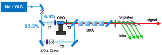
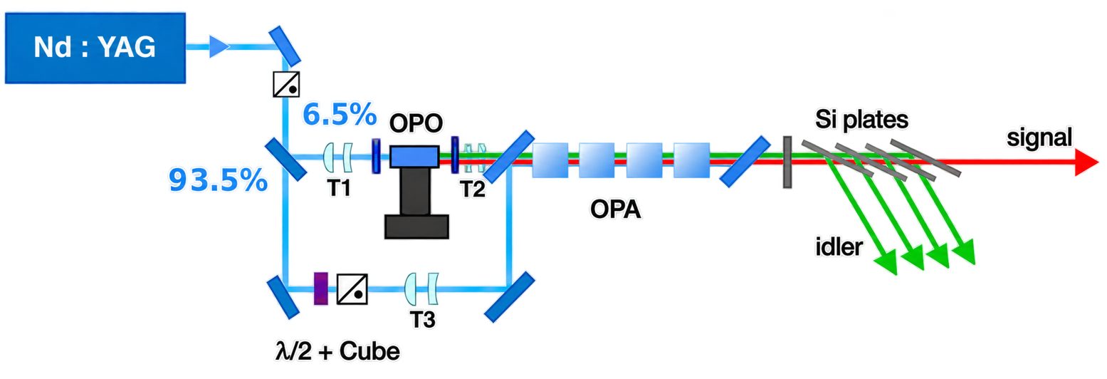
Figure 3 shows the experimental setup of the MOPA system. In this setup, the pump laser for the OPO and the OPA is the same. A beam splitter with a reflectivity of 6.5% for the Ppolarized Nd:YAG beam is placed in front of the OPO.
Figure 3.
Experimental setup of the MOPA system used for comparison. Of the available pump pulse energy, 6.5% is directed to the OPO and 93.5% is used to pump the OPA stages. Silicon plates are used to separate the signal from the idler, and dielectric mirrors are used to remove the residual pump beam.
The diameter of the reflected beam is then reduced to 1/3 with respect to the incoming beam with the telescope (T1). After the OPO, the signal and idler beam sizes are increased by a factor of two using a second telescope (T2).
A third telescope (T3) is used to reduce the beam size of the transmitted part of the pump beam by 1/3 to 6 mm. Every OPA is placed on its own rotating mount and is adjusted to its optimal angle to amplify the signal and idler beams. A λ/2 wave plate and a polarizing cube are used to control the pump energy input in the OPA.
The Nd:YAG pump is then recombined with the signal and idler beams to amplify them with four OPAs. These four OPAs are also cut at θ = 53.6° (16 mm long) and are placed in a way to compensate for the walk-off between the signal and the idler [20]. They also have a SiO2:HfO2 coating applied to all crystals to increase the transmission for the wavelengths of the pump, signal, and idler.
After the OPA chain, the pump is separated from the signal and idler with two dichroic mirrors (reflectivity for the pump beam is 98% for each mirror). The signal is separated from the idler with four Si plates placed at the Brewster angle. The signal beam and the idler beam do not have the same polarization. A total of 71.4% of the idler beam is reflected for each Si plate, and close to 100% of the signal beam is transmitted. After the four filters, 99.3% of the energy of the idler is removed from the signal.
3. Simulations
We have used the SNLO package [33] under Matlab R2021a (version 21.1) to simulate the HE-OPO setups.
All radiation inside the cavity of the OPO is modeled as a sequence of time slices, each separated by the time the light takes to travel a round-trip in the OPO cavity. The evolution of these slices is determined by solving the paraxial Maxwell equations in retarded time as they move through the cavity [31,33]. For every time slice, the transverse profile of the pump optical field is laid out on a rectangular grid and carried forward to the input mirror of the OPO. Here, it merges with the existing pump light within the cavity. This combined pump field is then circulated back to the input mirror, repeating this cycle for the length of the pump pulse. The same method is used for the seeded signal wave, while the third wave, the idler, is created solely within the OPO cavity. No external seed was used in the experiment, and the signal wave was assumed to build up within the OPO cavity.
Reference [32] modeled the frequency-mixing process by numerically integrating the corresponding equations under the plane-wave approximation. The model developed by A. V. Smith et al. [33,34], which is used here, additionally accounts for transverse beam profiles, diffraction, and spatial walk-off. They assume that the difference in the group velocity of all three signals (signal, idler, and pump) does not influence the gain of the OPO. This is why we have used the subroutine 2D-cav-LP.
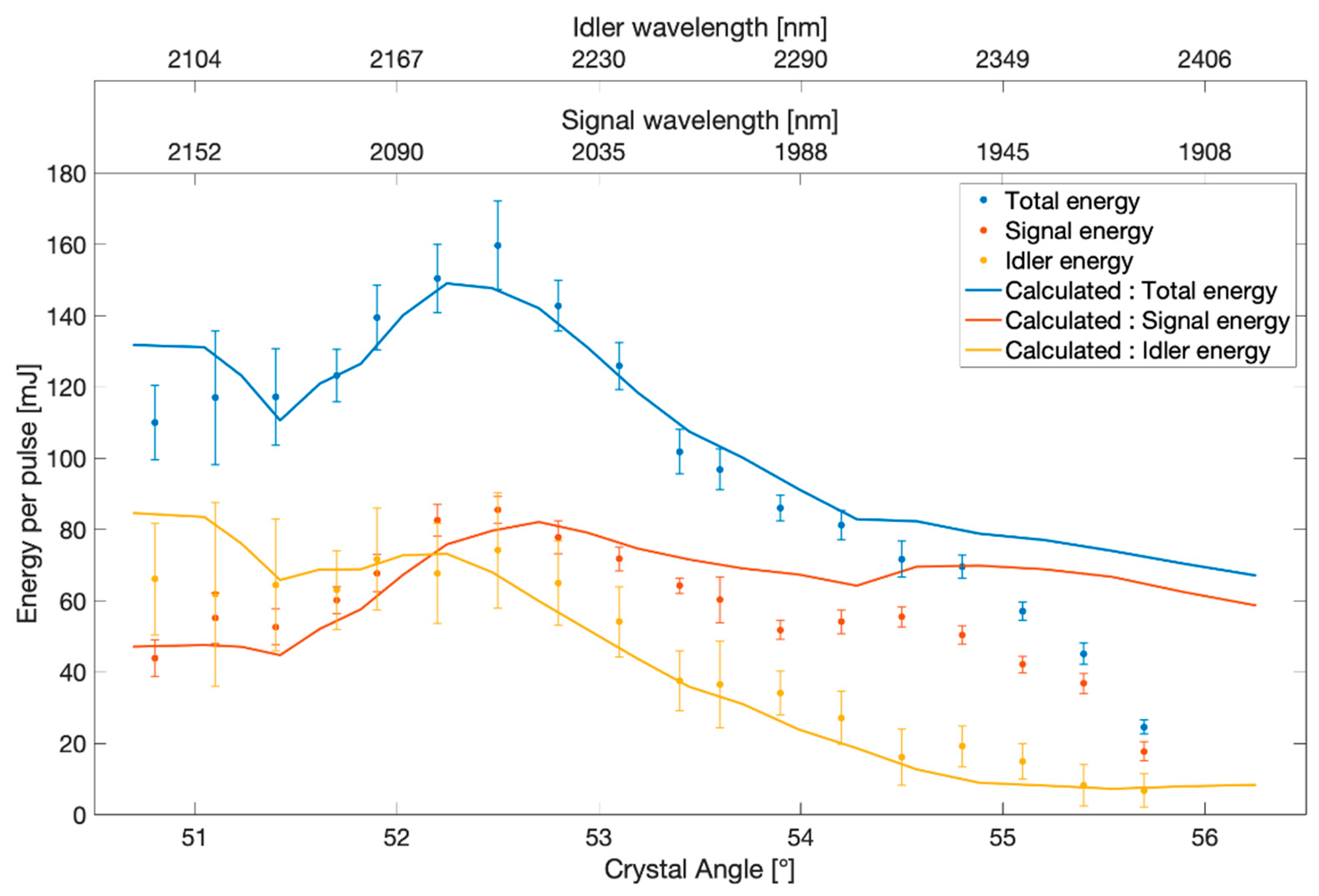
In a first step, we have optimized the reflectivity of the used mirrors to obtain the best conversion from 1064 nm to 2005 nm for the signal and 2267 nm for the idler when the HE-OPO is used in normal incidence (Figure 1). As a starting point, we have set the reflectivity of the output mirror (M2) to 100% for the pump beam (1064 nm). Also, we have set the reflectivity of the input mirror (M1) to 100% for the idler and the signal because we do not want to have the signal and the idler beam reflected back to the pump laser. We calculated the reflectivity of the input mirror for the pump and the reflectivities of the output mirror for the signal and idler wavelengths in steps of 1%. The calculations indicated that increasing the pump reflectivity of M1 beyond 20% could improve the conversion efficiency. However, such a configuration is not suitable for the experimental setup because a larger fraction of the pump energy would be reflected back toward the laser. Even a slight misalignment of the OPO could, therefore, damage optical components located near the laser. We consequently selected the compromise reflectivities listed in Table 1. The cavity mirrors were fabricated in-house, and their production is technically demanding because the available coating system imposes practical limitations on the achievable coating designs and reflectivities. The selected values, therefore, represent a compromise between the calculated optimum, operational safety, and the reflectivities that could be reliably produced. Using these experimentally implemented reflectivities, we calculated the wavelength dependence of the signal and idler pulse energies shown in Figure 4.
Figure 4.
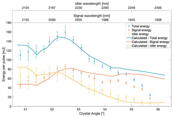
Measured signal, idler, and total output pulse energies as functions of the crystal angle. The upper horizontal axes indicate the corresponding signal and idler wavelengths. The solid curves show the results of the SNLO calculations multiplied by a factor of 0.85 to facilitate comparison with the experimental data.
Numerical Simulation
The HE-OPO can be used to produce a signal beam tunable between 1900 nm and 2160 nm and an idler beam tunable between 2100 nm and 2400 nm (Figure 4). The calculated curve reflects the general behavior of the optical setup. (The maximum energies in the calculations and in the experiment occur at the same angle). However, the deviation at larger tuning angles can be explained by a change in the beam path in the resonator. The crystal is actively turned in the cavity with an angle α. Rotating the crystal changes the beam path and the optical path length inside the crystal, as well as the effective path through the anti-reflection coatings. In our simulations, we only vary the angle θtot = θ0 + α. The maximum reachable theoretical energy is about 15% higher than the measurement. The reason for this might be linear and nonlinear processes (e.g., sum frequency generation) in the crystal and mirrors. The maximum signal pulse energy at 2005 nm was 90 mJ for a pump pulse energy of 765 mJ. The corresponding signal beam had an M2 value of 10. Figure 2b demonstrates the correlation between the wavelengths of the SFG processes (signal + pump and idler + pump), which has been used to calculate the signal and idler wavelengths. We measured for an angle of θ = 54.8° a peak at λs+p = 688.71 nm (signal + pump) and a second peak at λi+p = 730.69 nm (idler + pump). This corresponds to a signal wavelength of 1952.59 nm and an idler wavelength of 2332.53 nm.
4. Comparison with the MOPA System
The MOPA system has a comparable wavelength range, but tuning its wavelength is not as straightforward as in the HE-OPO. The OPO and all four OPA crystals are mounted on computer-controlled motorized rotation stages (PRM1Z8, Thorlabs, Newton, NJ, USA). When tuning to a new wavelength, the angular positions of all five crystals have to be optimized sequentially with a precision better than 0.1°. This procedure typically requires a few minutes. Once the optimum positions have been determined, however, they can be stored and subsequently recalled, allowing the system to switch between previously calibrated wavelengths within a few seconds. In comparison, wavelength tuning of the HE-OPO requires adjustment of only a single crystal.
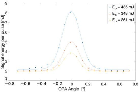
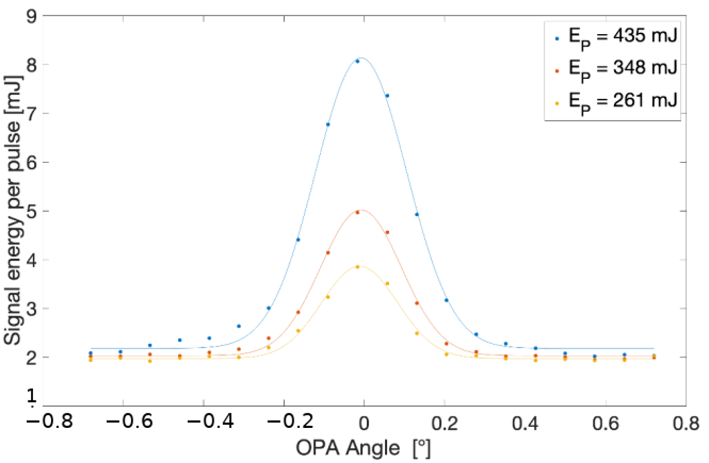
Figure 5 shows the energy of an amplified signal after the first OPA as a function of the OPA crystal angle and the pump energy. For these experiments, the OPO is tuned to 2005 nm.
Figure 5.
Signal pulse energy at 2005 nm measured after the first OPA as a function of the OPA crystal angle for different pump pulse energies. The signal pulse energy delivered by the OPO and injected into the first OPA was fixed at 3 mJ for all measurements.
We achieved a maximum signal energy for the MOPA of 116 mJ for a pump of 909 mJ with four KTP crystals. The M2 parameter of the signal after the fourth OPA was 10. Table 2 shows the energy, gain, and M2 parameter after each crystal.
Table 2.
Maximum signal pulse energy, stage gain, and M2 value after each OPA stage. The final beam quality is comparable to that of the HE-OPO.
The M2 parameter of the signal decreases after its first amplification and then increases again (Table 2). The signal gain of each OPA stage is defined as the ratio of the output signal pulse energy to the input signal pulse energy. The OPO is known to produce signals with poor M2 values when the diameter of the pump beam is too large (due to a high Fresnel number [34,35]). We observe that the gain is optimal for the first few OPAs and then decreases to a value close to 1. This may result from degradation of the pump, signal, and idler beam profiles after each amplification. We have observed a better M2 value after the first OPA than after the OPO in all our measurement series.
The reason could be the significantly better M2 of our pump laser compared to the M2 of the signal input of the first OPA.
An improved M2 value can be obtained by placing an iris just after the OPO telescope. This iris improves the signal and idler beam profiles after the OPO, and a good M2 value is still conserved after multiple amplification stages, as seen in Table 3. However, the maximum signal energy was reduced. For the experiment, we used an iris with a diameter of 2 mm and obtained a maximum energy of 2.6 mJ after the 4th OPA with a better M2 parameter.
Table 3.
MOPA M2 value was measured after each KTP crystal using an iris after the OPO. The iris diameter was 2 mm. We have received a maximal pulse energy of 2.6 mJ after the 4th OPA.
The high-energy OPO is easier to set up and align. However, the intracavity intensity in the HE-OPO can approach the laser-induced damage threshold of the cavity mirrors or of the anti-reflection coatings on the KTP crystal. In the MOPA system, only 6.5% of the available Nd:YAG pump pulse energy is directed to the OPO stage, while the remaining energy is used to pump the four OPA stages. Consequently, the pulse energy circulating in the oscillator is substantially lower, although the local intensity also depends on the beam diameter, pulse duration, and cavity enhancement. The wavelength of the HE-OPO is easier to measure. The signal, idler, and pump energies are so high in the OPO cavity that a sum-frequency generation between the signal and the pump and the idler and the pump can be observed. The resulting frequencies are in the visible spectrum and are easily measured. This is not the case for the MOPA. The intensity in its OPO cavity is too low to generate the sum frequency. The signal and idler wavelengths can be measured with a near-IR spectrometer. A different, cheaper method is to use a β-BaB2O4 crystal (BBO) to generate the second harmonic. The wavelength of the second harmonic is between 973 nm and 1044 nm and can be measured with a standard fiber spectrometer. Our calculation predicts that the M2 parameter should be better for the MOPA system (due to a lower Fresnel number for its seed cavity), but in our experiments, we measured approximately the same values for both setups. However, it is possible to improve the MOPA beam profile with an iris after the OPO.
To place the performance of the present systems in context, Table 4a,b compare their main parameters with selected previously reported high-energy OPO and OPO/OPA systems operating in the 2 µm spectral region.
Table 4.
(a) Comparison of system configuration, pump conditions, and operating wavelengths. (b) Comparison of output energies, beam quality, and wavelength-tuning characteristics.
5. Summary
We demonstrated the generation of wavelength-tunable signal and idler pulses using a high-energy, single-crystal KTP OPO directly pumped by an Nd:YAG laser at 1064 nm, with measured pulse durations of approximately 7 ns for both the signal and idler at the operating point corresponding to 2005 nm signal and 2267 nm idler. The signal wavelength was tunable from 1.90 to 2.17 µm, while the corresponding idler wavelength covered the range from 2.10 to 2.40 µm. A maximum signal pulse energy of 90 mJ was obtained at a wavelength of 2005 nm for a pump pulse energy of 765 mJ. The measured dependence of the signal and idler pulse energies on the crystal angle was in good agreement with the SNLO calculations. For comparison, a MOPA system consisting of one OPO and four OPA stages was investigated. This system generated a maximum signal pulse energy of 116 mJ at 2005 nm for a pump pulse energy of 909 mJ. Both systems exhibited comparable beam-propagation factors, with M2 values of approximately 10. Although the MOPA system produced a slightly higher signal pulse energy, wavelength tuning required the individual realignment of all four OPA crystals. In contrast, the wavelength of the HE-OPO could be tuned by rotating a single KTP crystal. A major advantage of the HE-OPO is its straightforward tunability, which makes it an ideal laser source for high-power wavelength-dependent measurements.
Author Contributions
Conceptualization, B.W. and M.P.; methodology, B.W.; software, P.-É.C.; validation, Y.K., B.S., P.-É.C. and B.W.; formal analysis, Y.K. and P.-É.C.; investigation, P.-É.C.; data curation, P.-É.C. and Y.K.; writing—original draft preparation, B.W.; writing—review and editing, B.W.; visualization, P.-É.C. and Y.K.; supervision, B.W.; project administration, B.W.; funding acquisition, B.W. and M.P. All authors have read and agreed to the published version of the manuscript.
Funding
This research was funded by FRQNT grant number #147660 and NSERC grant number #1281202.
Data Availability Statement
The data presented in this study are available from the corresponding author upon reasonable request.
Acknowledgments
We thank Mario Martin for his technical help during the experiment, and Souleymane Toubou Bah for the calculation and fabrication of the mirrors and anti-reflection coatings used in the experiments. The first two authors, Paul-Émile Chantrel and Yacine Kassimi, contributed equally to this publication.
Conflicts of Interest
The authors declare no conflicts of interest.
References
- Robiette, A.G.; Duncan, J.L. High Resolution vibration-rotation spectroscopy. Ann. Rev. Phys. Chem. 1983, 34, 245. [Google Scholar] [CrossRef] [Scilit]
- des Aulnois, J.G.; Szymanski, B.; Colin, A. Tunability improvement of a doubly resonant OPO for fast and high-resolution gas spectroscopy. In Proceedings of the Next-Generation Spectroscopic Technologies XI, 1065707 (14 May 2018); SPIE: Bellingham, WA, USA, 2018. [Google Scholar] [CrossRef] [Scilit]
- Baxter, J. Optical coherence tomography, Tunable for medicine. Nat. Photonics 2012, 6, 70. [Google Scholar]
- Terry, J.A.C.; McEwan, K.J.; Payne, M.J.P. Advanced Solid-State Lasers; Vol. 19 of Trends in Optics and Photonics Series; Optical Society of America: Washington, DC, USA, 1998; pp. 236–239. [Google Scholar]
- Piotrowski, M.; Spindler, G.; Bogas-Droy, A.; Hildenbrand-Dhollande, A. CdSiP2 Optical Parametric Oscillator Pumped by a Nanosecond Ho:LLF Laser at 2.06 μm with Non-Collinear Phase-Matching. Photonics 2024, 11, 1190. [Google Scholar] [CrossRef] [Scilit]
- Mei, J.; Zhong, K.; Wang, M.; Liu, P.; Xu, D.; Wang, Y.; Shi, W.; Yao, J.; Norwood, R.A.; Peyghambarian, N. Compact high-repetition-rate terahertz source based on difference-frequency generation from an efficient 2-μm dual-wavelength KTP OPO. In Proceedings of the Infrared, Millimeter-Wave, and Terahertz Technologies IV; SPIE: Bellingham, WA, USA, 2016; Volume 10030. [Google Scholar]
- Lippert, E.; Nicolas, S.; Arisholm, G.; Stenersen, K.; Rustad, G. Mid-infrared laser source with high power and beam quality. Appl. Opt. 2006, 45, 3839–3845. [Google Scholar] [CrossRef] [Scilit]
- Yumoto, M.; Saito, N.; Urata, Y.; Wada, S. 128 mJ/Pulse, Laser-Diode-Pumped, Q-Switched Tm:YAG Laser. IEEE J. Sel. Top. Quantum Electron. 2014, 21, 364–368. [Google Scholar] [CrossRef] [Scilit]
- Fonnum, H.; Lippert, E.; Haakestad, M.W. 550 mJ Q-switched cryogenic Ho: YLF oscillator pumped with a 100 W Tm: Fiber laser. Opt. Lett. 2013, 38, 1884–1886. [Google Scholar] [CrossRef] [Scilit]
- Wu, J.H.; Du, S.F.; Bo, Y.; Wang, Z.C.; Gao, Y.; Wang, H.L.; Liu, D.X.; Cui, D.F.; Peng, Q.J. Experimental and theoretical research on laser diode side-pumped Tm, Ho: YAG laser. Appl. Phys. B 2024, 130, 55. [Google Scholar] [CrossRef] [Scilit]
- Honea, E.C.; Beach, R.J.; Sutton, S.B.; Speth, J.A.; Mitchell, S.C.; Skidmore, J.A.; Emanuel, M.A.; Payne, S.A. 115-W Tm: YAG Diode-Pumped Solid-State Laser. IEEE J. Quantum Electron. 1997, 33, 1592–1600. [Google Scholar] [CrossRef] [Scilit]
- Simakov, N.; Hemming, A.; Clarkson, W.A.; Haub, J.; Carter, A. A cladding-pumped, tunable holmium doped fiber laser. Opt. Express 2013, 21, 28415. [Google Scholar] [CrossRef] [Scilit]
- Liu, Y.; Song, J.; Peng, Y.; Li, E.; Long, Y.; Sun, J.; Shen, L.; Liu, Y.; Zhu, J.; Leng, Y.; et al. 162.6 mJ high-energy and high-efficiency KTP optical parametric oscillator at 2 μm. Chin. Opt. Lett. 2025, 23. [Google Scholar] [CrossRef] [Scilit]
- Behnke, L.; Salumbides, E.J.; Göritz, G.; Mostafa, Y.; Engels, D.; Ubachs, W.; Versolato, O. High-energy parametric oscillator and amplifier pulsed light source at 2-μm. Opt. Express 2023, 31, 24142–24156. [Google Scholar] [CrossRef] [Scilit]
- Giordmaine, J.A.; Miller, R.C. Tunable coherent parametric oscillation in LiNbO3 at optical frequencies. Phys. Rev. Lett. 1965, 14, 973–976. [Google Scholar] [CrossRef] [Scilit]
- Chen, T.; Jiang, P.; Yang, D.; Hu, C.; Wu, B.; Shen, Y. High-power PPMgLN-based optical parametric oscillator pumped by a linearly polarized, semi-fiber-coupled acousto-optic Q-switched fiber master oscillator power amplifier. Appl. Opt. 2013, 52, 6316. [Google Scholar] [CrossRef] [Scilit]
- Mei, J.; Zhong, K.; Liu, Y.; Shi, J.; Qiao, H.; Xu, D.; Shi, W.; Yao, J. Compact efficient and widely tunable 2 mu high repetition-rate optical parametric oscillators. Opt. Commun. 2018, 426, 119. [Google Scholar] [CrossRef] [Scilit]
- Arisholm, G.; Lippert, E.; Rustad, G.; Stenersen, K. Efficient conversion from 1 to 2 mu by a KTP-based ring optical parametric oscillator. Opt. Lett. 2002, 27, 1336. [Google Scholar] [CrossRef] [Scilit]
- Chen, S.Y.; Yang, Y.F.; Li, Y.F.; Wang, G.; Yu, Y.; Du, H.Y.; Cao, F.L.; Yin, H.W.; Zhu, C.Y.; Wang, Y.L.; et al. Efficient 10 ns-scale 2-μm optical parametric oscillator based on 1064 nm pump source. Front. Phys. 2024, 12, 1383254. [Google Scholar] [CrossRef] [Scilit]
- Nordseth, Ø. Master oscillator/power amplifier system for optical parametric conversion of high energy pulses from 1 to 2 μm. In FFI/RAPPORT-2004/02159; Norwegian Defence Research Establishment: Kjeller, Norway, 2004. [Google Scholar]
- Coetzee, R.S.; Zheng, X.; Fregnani, L.; Laurell, F.; Pasiskevicius, V. Narrowband, tunable, 2 µm optical parametric master-oscillator power amplifier with large-aperture periodically poled Rb: KTP. Appl. Phys. B 2018, 124, 124. [Google Scholar] [CrossRef] [Scilit]
- Li, T.; Meng, J.; Liu, G.; Liu, Z. High-Power KTiOAsO4 Optical Parametric Oscillator at 300 Hz. Photonics 2025, 12, 270. [Google Scholar] [CrossRef] [Scilit]
- Akhmanov, S.A.; Kovrigin, A.I.; Piskarskas, A.S.; Fadeev, V.V.; Khokhlov, R.V. Observation of parametric amplification in the optical range. Jetp Lett. 1965, 2, 191–193. [Google Scholar]
- ISO/TR 11146-3:2004(E); Lasers and Laser-Related Equipment—Test Methods for Laser Beam Widths, Divergence Angles and Beam Propagation Ratios—Part 3: Intrinsic and Geometrical Laser Beam Classification, Propagation and Details of Test Methods. International Organization for Standardization: Geneva, Switzerland, 2004. Available online: https://www.iso.org/standard/77769.html (accessed on 30 August 2026).
- Smith, A.V.; Bowers, M.S. Image-rotating cavity designs for improved beam quality in nanosecond optical parametric oscillators. J. Opt. Soc. Am. B 2001, 18, 706–713. [Google Scholar] [CrossRef] [Scilit]
- Tiihonen, M.; Pasiskevicius, V.; Laurell, F.; Jonsson, P.; Lindgren, M. A compact OPO/SFG laser for ultraviolet biological sensing. In Proceedings of the International Society for Optical Engineering; SPIE: Bellingham, WA, USA, 2004; Volume 5332. [Google Scholar]
- Shao, J.; Fan, Z. Laser thin films with very high damage threshold. In Proceedings of the SPIE 5963, Advances in Optical Thin Films II, 596312 (4 October 2005); SPIE: Bellingham, WA, USA, 2005. [Google Scholar]
- Oliver, J.B. Evaporated HfO2/SiO2 Optical Coatings and Modifications for High-Power Laser Applications. Ph.D. Thesis, University of Rochester, Rochester, NY, USA, 2012. [Google Scholar]
- Xu, C.; Li, D.; Ma, J.; Jin, Y.; Shao, J.; Fan, Z. Influence of SiO2 additional layers on the laser induced damage threshold of Ta2O5 films. Opt. Laser Technol. 2008, 40, 545–549. [Google Scholar] [CrossRef] [Scilit]
- Stolz, C.J.; Génin, F.Y.; Reitter, T.A.; Molau, N.E.; Bevis, R.P.; von Gunten, M.K.; Smith, D.J.; Anzellotti, J.F. Effect of SiO2 overcoat thickness on laser damage morphology of Hf2/S2O2 Brewster’s angle polarizers at 1064 nm. In Laser-Induced Damage in Optical Materials: 1996; Proc. SPIE 2966; SPIE: Bellingham, WA, USA, 1997; pp. 265–272. [Google Scholar]
- Smith, A.V.; Bowers, M.S. Phase distortions in sum-and difference-frequency mixing in crystals. J. Opt. Soc. Am. B 1995, 12, 49. [Google Scholar] [CrossRef] [Scilit]
- Breteau, J.M.; Jourdain, C.; Lepine, T.; Simon, F. Numerical Simulation and Realization of a KTP Optical Parametric Oscillator. In Advanced Solid State Lasers; Pinto, A., Fan, T., Eds.; OSA Proceedings Series; Paper NF8; Optica Publishing Group: Washington, DC, USA, 1993. [Google Scholar]
- Smith, A.V. How to select nonlinear crystals and model their performance using SNLO software. In Proceedings of the Nonlinear Materials, Devices, and Applications; SNLO Nonlinear Optics Code Available from Smith, A.V., Photonics, A.S., Albuquerque, N.M.; SPIE: Bellingham, WA, USA, 2000; Volume 3928, pp. 62–69. [Google Scholar]
- Smith, A.V.; Alford, W.J.; Raymond, T.D.; Bowers, M.S. Comparison of a numerical model with measured performance of a seeded, nanosecond KTP optical parametric oscillator. J. Opt. Soc. Am. B 1995, 12, 2253–2267. [Google Scholar] [CrossRef] [Scilit]
- Anstett, G.; Borsutzky, A.; Wallenstein, R. Investigation of the spatial beam quality of pulsed ns-OPOs. Appl. Phys. B 2003, 76, 541–545. [Google Scholar] [CrossRef] [Scilit]

Disclaimer/Publisher’s Note: The statements, opinions and data contained in all publications are solely those of the individual author(s) and contributor(s) and not of MDPI and/or the editor(s). MDPI and/or the editor(s) disclaim responsibility for any injury to people or property resulting from any ideas, methods, instructions or products referred to in the content. |
© 2026 by the authors. Licensee MDPI, Basel, Switzerland. This article is an open access article distributed under the terms and conditions of the Creative Commons Attribution (CC BY) license.