


Abstract
To address the multi-sensor collaborative calibration challenges in laser 3D projection systems, a pose calibration method integrating binocular vision and laser ranging is proposed. A multi-coordinate system fusion framework encompassing the camera coordinate system, galvanometer coordinate system, and workpiece coordinate system is established. Through the calculation of reference pose matrices and real-time transformations, adaptive calibration under arbitrary workpiece placements is achieved. Experimental results demonstrate that within a working range of 1.5–2.5 m, the calibration error is 45.5 m, meeting the high-precision requirements of aerospace precision machining and assembly.
1. Introduction
Since the first ruby laser in the world was successfully developed by the American physicist Theodore Maiman in 1960, the laser field has witnessed continuous innovation and breakthroughs, giving rise to a series of cutting-edge industries based on laser applications and increasingly becoming one of the key forces driving scientific and technological progress as well as economic development [1]. Owing to its advantages of high precision and high performance, laser technology has played a crucial role in numerous fields, including scanning imaging, laser engraving, and component manufacturing [2,3,4]. As a cutting-edge field of opto-mechatronic integration, laser 3D projection measurement technology serves as a key enabling technology in digital and intelligent manufacturing systems. Leveraging the characteristics of high-speed scanning galvanometers, it controls the rapid deflection of the laser beam by adjusting the two-axis rotation angles of the galvanometers. Based on the CAD model data of the designed contour, the laser beam scans the surface of the target workpiece. Taking advantage of the human visual persistence effect, the human eye perceives a continuously formed projected pattern, thereby achieving high-precision projection [5].
In the aerospace industry, traditional positioning and assembly processes rely on operators to physically measure components according to design models, followed by marking with center punches, drilling positioning, and welding at target locations. Assembly accuracy is dependent on component reference features to ensure mating parts are precisely positioned within design tolerance ranges [6,7]. However, for large-scale, complex-shaped components with high precision requirements such as aircraft skins and rocket fuel tanks, this method exhibits significant limitations. When the number of process reference features is insufficient or they are spatially distant from assembly locations, on-site measurement operations become more difficult, resulting in low first-pass assembly qualification rates, often requiring custom physical positioning fixtures for auxiliary alignment. The introduction of laser 3D projection technology provides an innovative solution to these challenges. By integrating machine vision and dynamic pose measurement technologies [8], intelligent assembly systems based on high-precision laser 3D projection establish a new digital assembly paradigm, providing operators with intuitive visual guidance [9] and greatly improving the accuracy and efficiency of large component assembly [10].
Within this technical framework, the laser 3D projection system essentially fulfills the role of a virtual positioning fixture. By directly mapping the digital design model onto dynamically adjustable optical positioning references, it overcomes the physical limitations of traditional rigid fixtures. The system can automatically generate customized guidance information based on the assembly requirements of different components [11], eliminating the need for dedicated physical tooling design for individual products. This flexible positioning paradigm, based on digital twin technology [12], not only significantly reduces the costs associated with fixture manufacturing and maintenance but also enables rapid response to design changes throughout the assembly process, providing a revolutionary solution for high-precision and high-efficiency assembly of large-scale components.
Achieving projection accuracy at the millimeter or even sub-millimeter level within a working range of several meters has become the core challenge for the application of this technology [13]. The accuracy of the projection system depends on the precision of the pose relationship calibration among multi-coordinate systems. A typical laser 3D projection system usually includes multiple reference coordinate systems, such as the camera coordinate system, the projection coordinate system, and the workpiece coordinate system. The key to achieving seamless mapping from 3D digital space to 2D physical projection plane lies in how to establish and integrate these coordinate systems with high precision.
Regarding the research status at home and abroad, early system calibration relied on high-precision targets and fixed fixtures. The relative position between the workpiece and the system was determined through offline measurement. For example, commercial systems from manufacturers such as FARO and Hexagon adopt high-precision measurement schemes combining pre-calibration with measuring arms and fixed reference points. Although these schemes achieved high accuracy, they lacked flexibility and were difficult to adapt to the convenient demand of workpieces in production fields [14]. To enhance flexibility, researchers attempted to introduce visual-assisted calibration. Sivertsen et al. developed a visual positioning system using cooperative targets, which can dynamically calculate the coordinate system transformation matrix by detecting cooperative targets in the projection area in real time, realizing accurate projection of assembly features and effectively reducing the dependence on fixed fixtures [15]. However, the stability may decrease when cooperative targets are occluded or under poor lighting conditions. In recent years, Chinese scholars have also carried out extensive research. Ren Yongjie et al. introduced a laser tracker into large-scale assembly field measurement. The high-precision ranging capability of laser tracker enhanced pose estimation accuracy and depth direction precision, providing an effective means for on-site high-precision calibration [16]. However, the relatively high equipment costs hindered widespread adoption. Hou Maosheng et al. proposed a self-calibration method for laser scanning projection systems fused with monocular vision, utilizing a planar target to solve the hand-eye relationship and simplifying the collaborative calibration process between the camera and the projection system [17].
In summary, existing research has made remarkable progress in improving the calibration accuracy and flexibility of laser 3D projection systems, but the following challenges remain: (1) Deep integration and unified modeling of multi-sensor data and multi-coordinate systems remain unresolved; (2) The calibration process remains highly dependent on cooperative targets or expensive external measurement equipments; (3) The system lacks adaptive calibration and real-time error compensation capabilities when dealing with workpieces placed arbitrarily.
To solve the above problems, this paper proposes and improves a high-precision calibration technology for laser 3D projection systems based on pose relationships. A multi-coordinate system fusion calibration framework integrating binocular vision and laser ranging is constructed. Through the establishment of a reference pose matrix and a real-time transformation solving model, the system achieves adaptive high-precision calibration for workpieces in arbitrary poses. Experimental results demonstrate that the maximum calibration error of the system is 45.5 m within the operational range of 1.5–2.5 m, providing reliable technical support for precision machining and assembly in the aerospace field.
2. Materials and Methods
This section details the composition of the laser 3D projection measurement system, the measurement principle, and the multi-coordinate system fusion calibration method, providing sufficient technical details for the replication of the experiment.
2.1. System Design and Measurement Principle
The laser 3D projection system in this study integrates two functions: precise workpiece positioning and laser projection of model patterns, as shown in Figure 1. This system features two adaptive workpiece recognition and positioning methods tailored for different types of workpieces. It can obtain the position information of the workpiece based on binocular vision through feature recognition, coordinate system registration and 3D spatial calculation in scenarios where the workpiece has cooperative features. It can also extract the workpiece pose through the cooperation of the laser ranging module and 2D scanning projection under non-cooperative feature conditions. For the projection function, after the pattern or shape of the projection task is formulated in the computer, the data is transmitted to the main control unit, which converts the position information into motion commands under the projection coordinate system. A 2D scanning galvanometer control card accurately drives the two-axis galvanometer to adjust the scanning trajectory of the laser. After optimization by the collimation and beam-expanding optical system, the laser spot forms a high-density scanning dot matrix on the workpiece. Due to the persistence of vision, discrete laser points dynamically synthesize continuous patterns to achieve high-precision 3D projection, providing a reliable digital positioning reference for processes such as composite material lamination, precision component assembly and surface spraying.
Figure 1.
Schematic Diagram of Functional Implementation for Laser 3D Projection System.
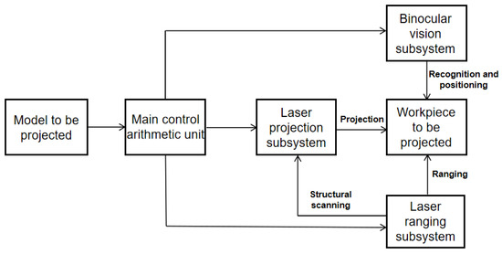
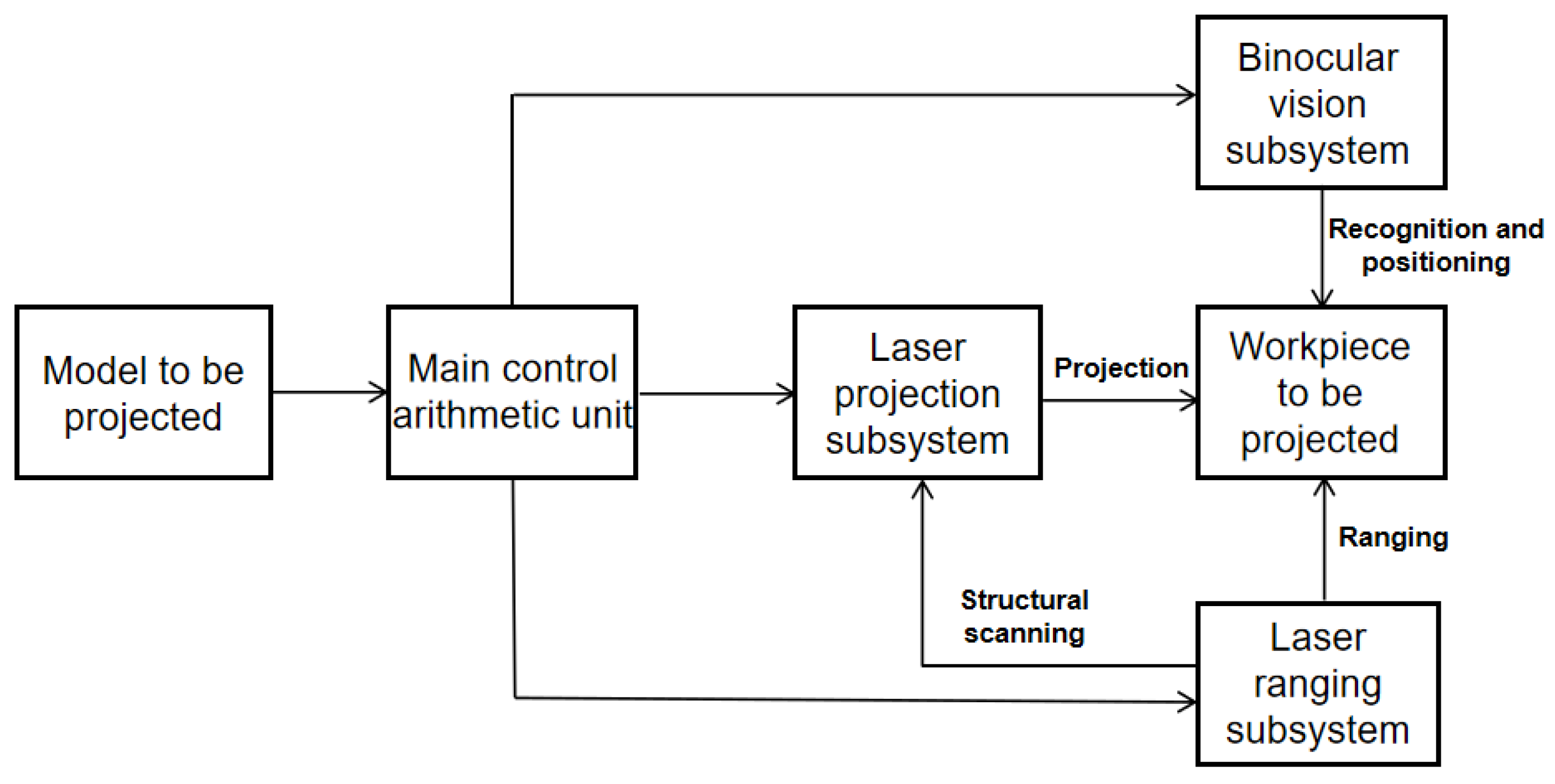
The system mainly consists of a binocular vision subsystem, a laser projection subsystem, a laser ranging subsystem, a main control unit and a computer. As shown in Figure 2, all modules of the system cooperate with each other through precise optical and electrical connections. The binocular vision subsystem is primarily responsible for capturing image information of workpieces and performing target recognition and positioning, mainly consisting of two cameras, lenses and an image processing module. The laser projection subsystem consists of a laser source, a 2D galvanometer control device and a collimating zoom optical system, responsible for implementing laser beam scanning and focusing. The laser ranging subsystem is located above the projection device and measures the distance between the workpiece and the system, mainly consisting of a ranging module, an optical transceiver system and a measurement and control circuit. The main control unit is located at the rear end of the system, mainly consisting of a power supply, a data interface unit, a data acquisition and processing unit, etc., responsible for the control and data processing of the entire system.
Figure 2.
Schematic diagram of collaborative relationships among subsystems.
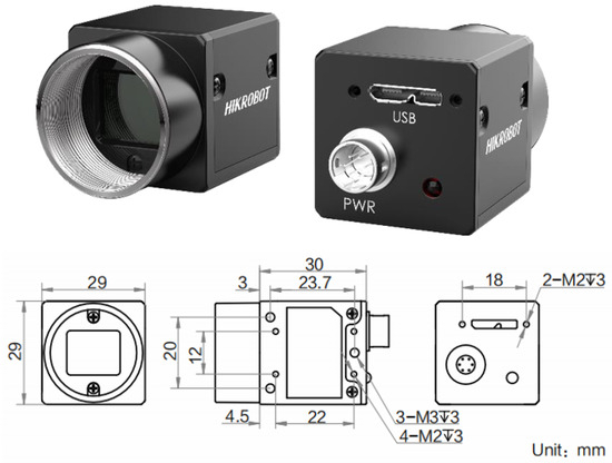
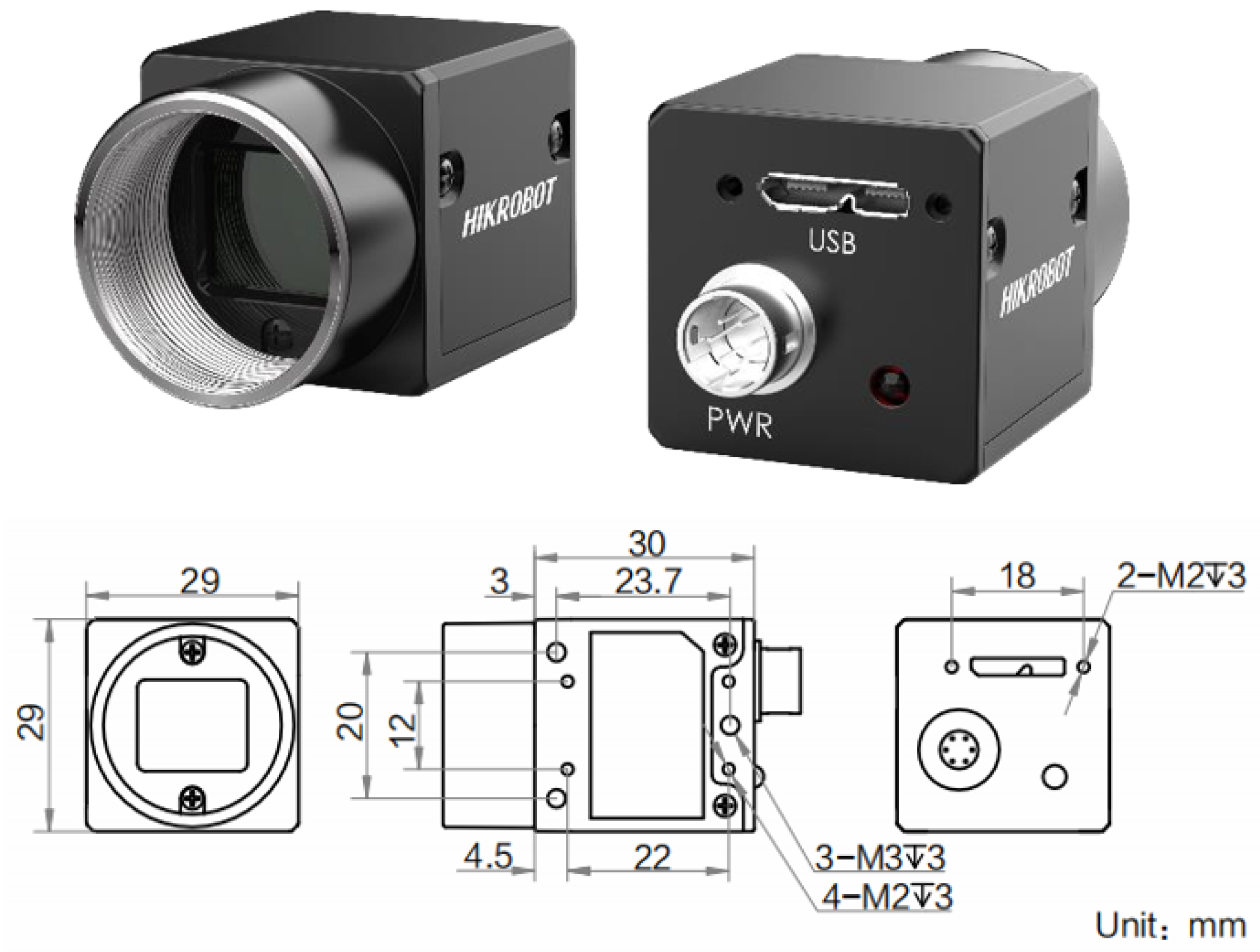
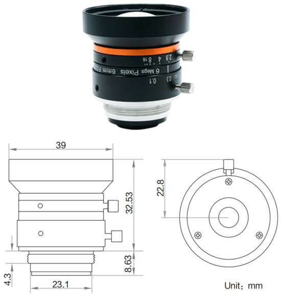
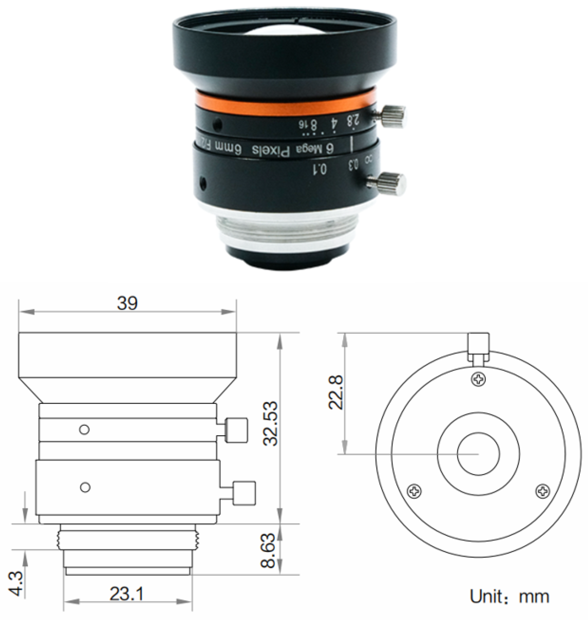
Considering the functions and structural characteristics of the binocular vision subsystem, the MV-CE060-10UM industrial area scan camera from Hikvision, Hangzhou, Zhejiang, China, as shown in Figure 3, is selected. It adopts the Sony IMX178 rolling-shutter CMOS sensor from Sony Semiconductor Solutions, Tokyo, Japan with a high resolution of 3072 × 2048, which meets the precision requirements for subsequent sub-pixel detection of checkerboard corners. The lens adopts the Hikvision MVL-HF0628M-6MPE industrial lens from Hikvision, Hangzhou, Zhejiang, China shown in Figure 4, with a fixed focal length of 6 mm, compatible with 1/1.8′′ sensors.Its field of view covers medium-distance measurement scenarios from 0.5 m to 5 m, satisfying the full-size inspection requirements of workpieces.
Figure 3.
Hikvision MV-CE060-10UM industrial area scan camera.
Figure 4.
Hikvision MVL-HF0628M-6MPE industrial lens.
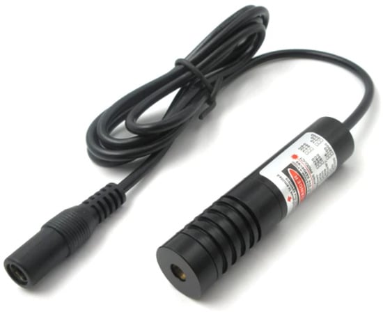
As the core execution unit of the laser 3D projection system, the laser projection subsystem usually requires the laser to operate continuously for a long time to ensure the integrity of projection and the comprehensiveness of subsequent processing. Based on comprehensive considerations, a 520 nm green light spot laser from Shenzhilei, Shenzhen, Guangdong, China, as shown in Figure 5, is adopted, with an output power of 5 mW. It provides excellent visibility, facilitating system debugging and real-time monitoring. Meanwhile, the laser at this wavelength can achieve reasonable energy absorption and reflection, laying a stable foundation for subsequent 3D projection and measurement.
Figure 5.
520 nm green light spot laser.
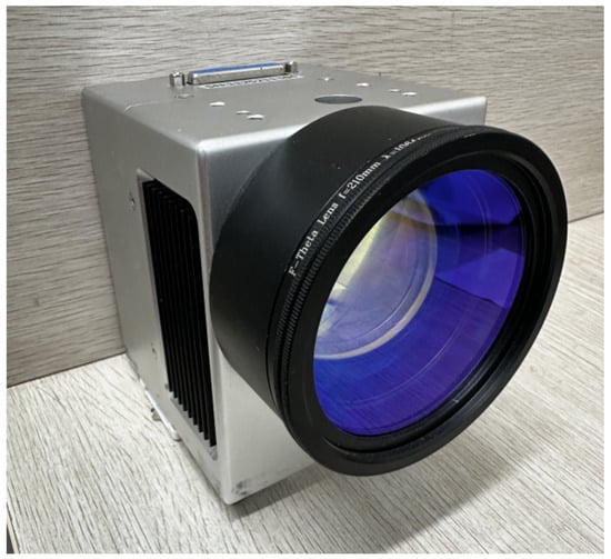
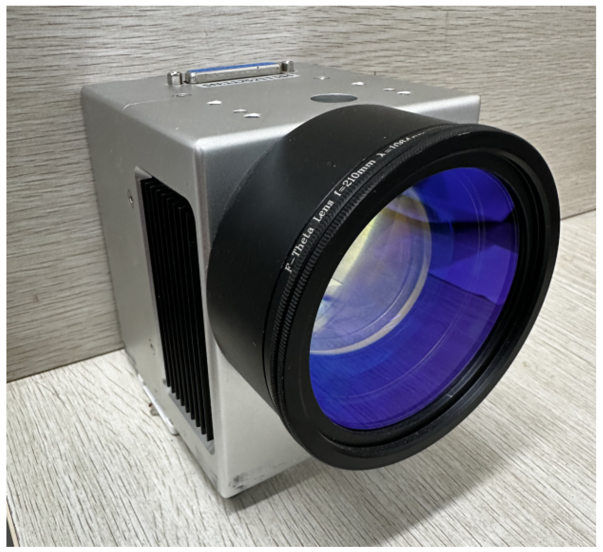
As a key actuating component of the projection subsystem, the performance of the 2D galvanometer directly affects the speed, accuracy, and flexibility of laser scanning, and determines the quality of projected patterns and system efficiency. In this study, the LEDY-10G high-speed digital galvanometer manufactured by Lier Optoelectronic, Foshan, Guangdong, China, as shown in Figure 6, is employed. A high-transmittance coated field lens with a focal length of 210 mm and a design wavelength of 1064 nm is installed in front of the galvanometer, which enables the laser beam to be precisely focused on the working surface, maintains a consistent laser spot size at different projection positions, reduces laser energy loss, and improves beam utilization efficiency. The galvanometer has a maximum scanning angle of , covering 95% of the working area within the field of view of the laser projection subsystem, ensuring that the laser can be projected onto all positions of the workpiece surface. It features an angular resolution of and a repeat positioning accuracy of , which can avoid pattern distortion or positioning errors caused by angular deviation in high-precision projection tasks, thus ensuring the consistency and reliability of projection. The minimum step response time is ≤0.3 ms, and the maximum operating frequency reaches 1000 Hz, enabling timely response to system commands.
Figure 6.
LEDY-10G high-speed digital galvanometer.
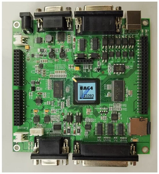
To meet the requirements of high-precision scanning, multi-mode control, and industrial-grade stability for the projection subsystem, the UMC4 digital laser marking control card from JPT Laser, Shenzhen, Guangdong, China, as shown in Figure 7, is used as the 2D galvanometer control card. It supports the XY2-100 digital galvanometer communication protocol and realizes high-precision control of the galvanometer angle through differential signals.
Figure 7.
UMC4 laser marking control card.
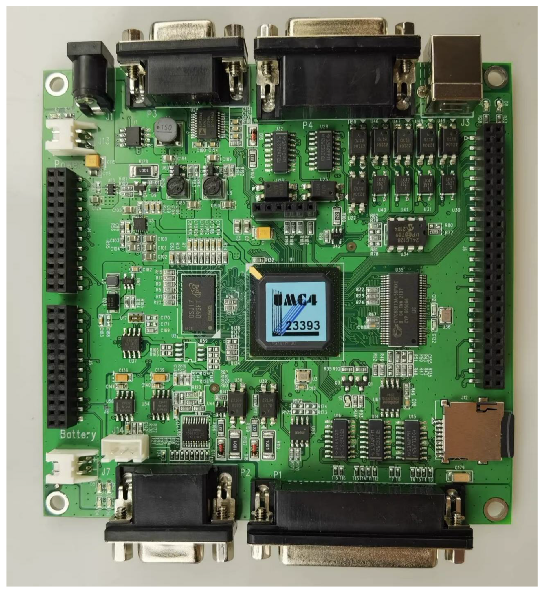
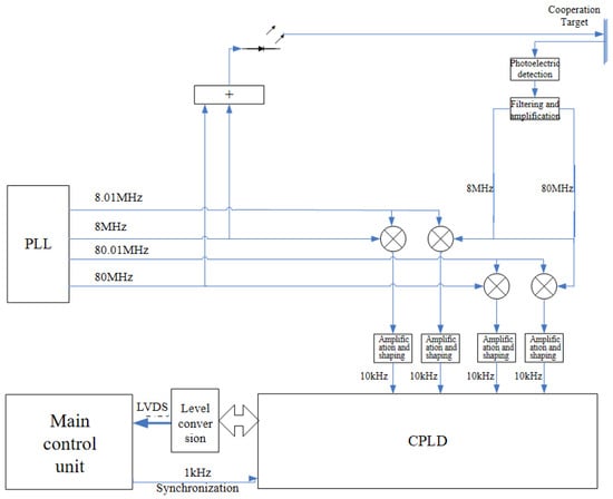
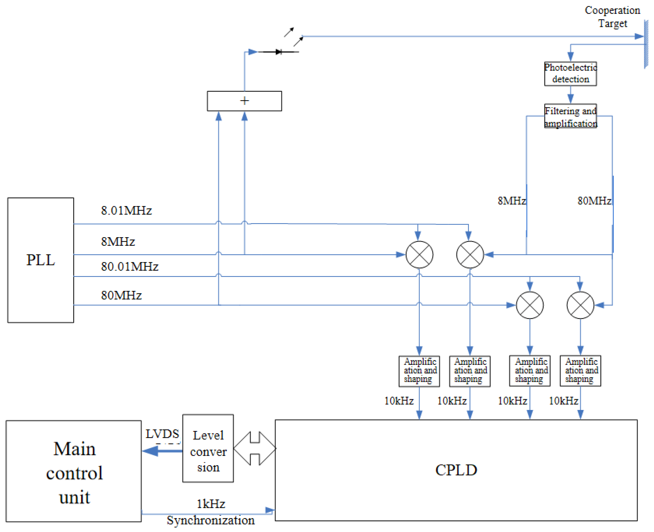
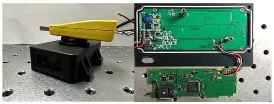
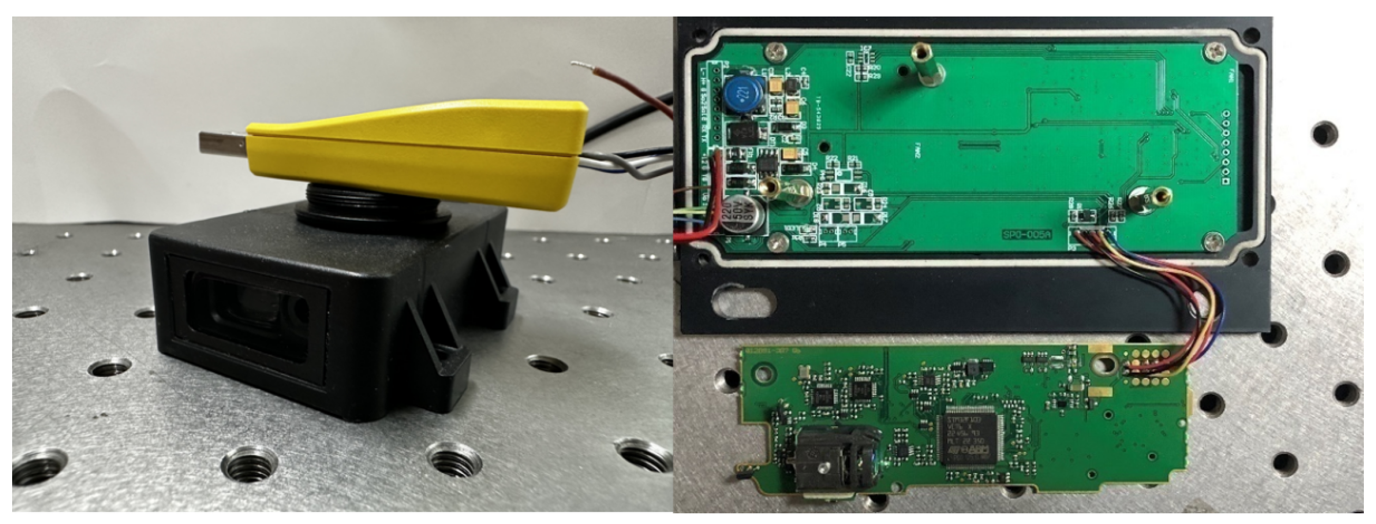
According to the requirements for measurement range, ranging accuracy, and measurement resolution of the laser ranging subsystem, this design as shown in Figure 8 is based on the difference-frequency phase measurement technique. It uses 8 MHz/80 MHz master oscillator and 8.01 MHz/80.01 MHz local oscillator to generate 10 kHz difference frequency signal, and realizes frequency synthesis with CDCE706 programmable phase-locked loop. A seventh-order Chebyshev filter converts the square wave into a sine wave. In the transmitting module, the 2N5109 microwave transistor is adopted to drive the laser for dual-frequency modulation. The receiving module uses an APD detector with temperature compensation and dual-channel variable gain amplification to ensure signal stability. In the mixing stage, a high-frequency and high-isolation dual-gate field-effect transistor is selected to reduce crosstalk. Then, the signal is shaped by LM293 and the phase difference is digitally measured by CPLD. The PCB design integrates a variety of anti-interference measures. Finally, the subsystem achieves a resolution of 0.1 mm, repeatability of mm, and a measurement range from 0.03 m to over 20 m. The module has a compact size and supports USB 3.0 communication, which can meet the requirements of high-precision industrial ranging and integration with laser projection systems. The physical prototype is shown in Figure 9.
Figure 8.
Schematic diagram of the overall circuit design for the laser ranging module.
Figure 9.
Physical diagram of the laser ranging module’s appearance and processing circuit.
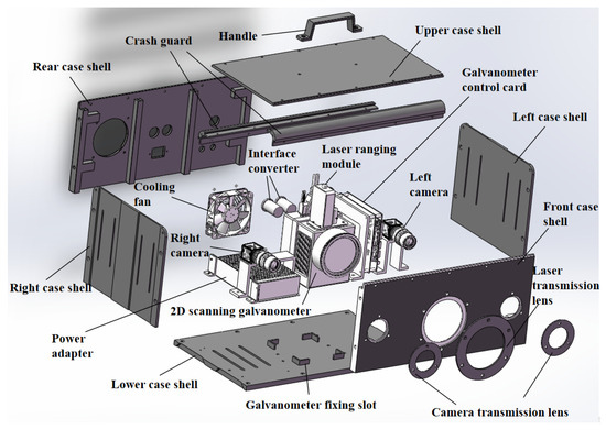
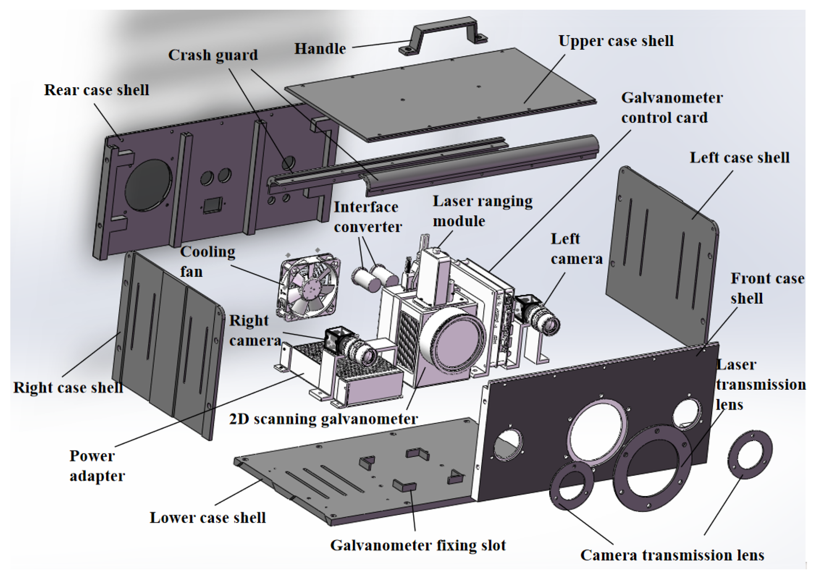
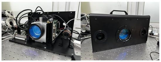
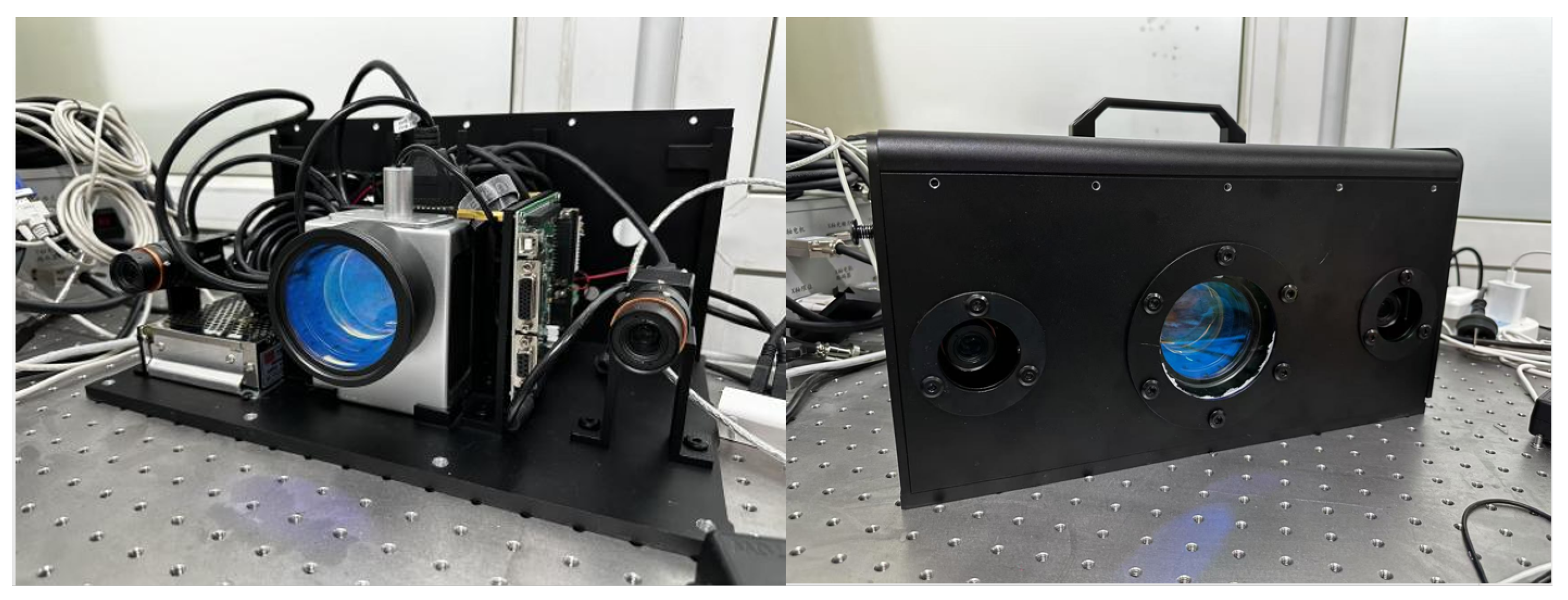
The structural design of the laser 3D projection system aims to achieve the organic integration of each functional module, ensuring that the system meets basic requirements such as protection and heat dissipation, while guaranteeing the precise collaborative operation of optical and electronic components. Based on the hardware selection and design described above, the overall structure of the laser 3D projection system developed in this study is shown in Figure 10. An integrated structural design is adopted, encompassing all hardware devices, their mounting and fixing structures, and the overall housing. A photograph of the fully assembled system is presented in Figure 11.
Figure 10.
Overall structural diagram of the laser 3D projection system.
Figure 11.
Overall physical diagram of the laser 3D projection system.
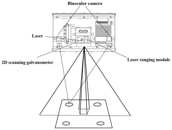
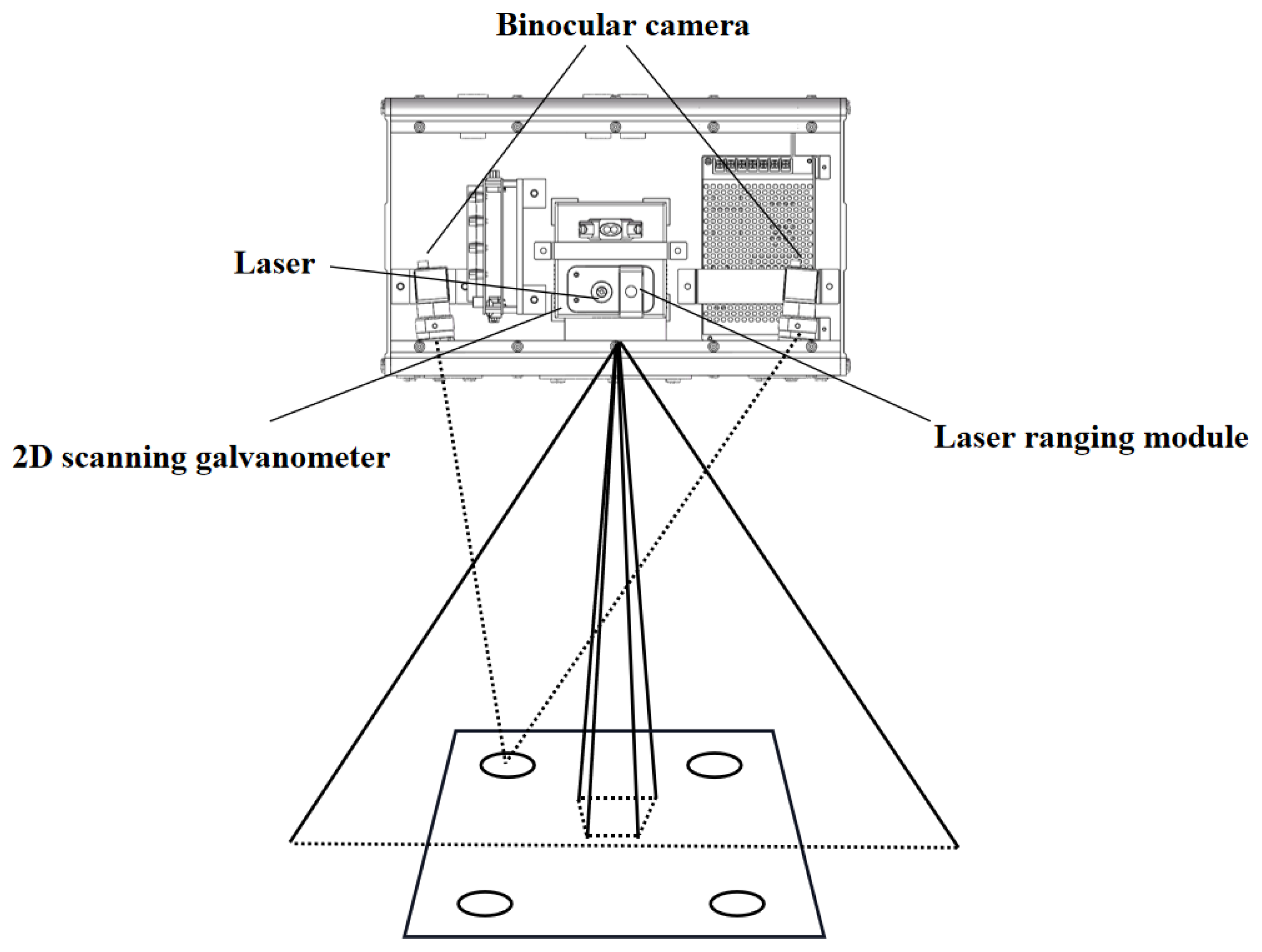
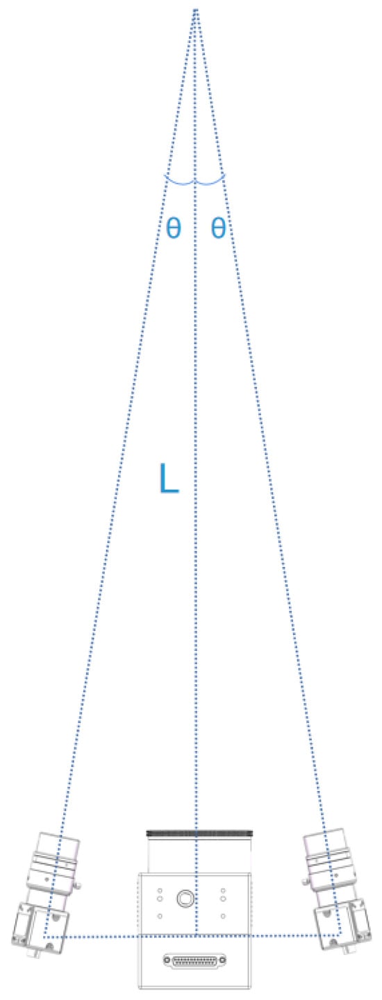
To improve the accuracy of subsequent calibration, in the structural design, the optical axes of the binocular cameras and the 2D scanning galvanometer are arranged on the same plane. The included angle between the principal optical axis of each camera and that of the galvanometer assembly is 4.57°, and the baseline distance between the two cameras is 300 mm. The principal optical axes of the three components intersect at a point 2000 mm away, with their positional relationship illustrated in Figure 12.
Figure 12.
Schematic diagram of the positional relationship between the binocular camera and the 2D scanning galvanometer.
Limited by the focal length and baseline distance of the binocular camera lens, when the working distance is less than 1.5 m, the camera cannot fully capture the overall image features of the standard workpiece within the imaging plane, resulting in the failure of feature point extraction and pose solution. Therefore, the region below 1.5 m is not within the effective measurement range of the system and does not require accuracy verification. In practical application scenarios such as aerospace and large-component assembly, workpieces are placed by fixtures or spreaders in a stable working range more than 1.5 m away from the equipment, and short-distance operation is rarely involved. Accordingly, considering both the field-of-view limitation of the binocular camera and actual engineering requirements, the effective calibration working range of the laser 3D projection measurement system in this study is set to 1.5–2.5 m.
2.2. Multi-Coordinate System Fusion Calibration Method
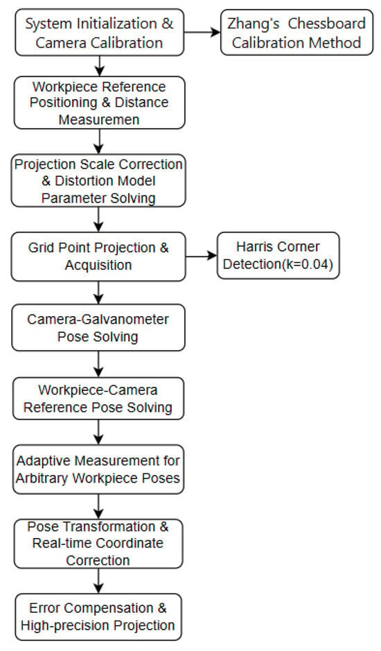
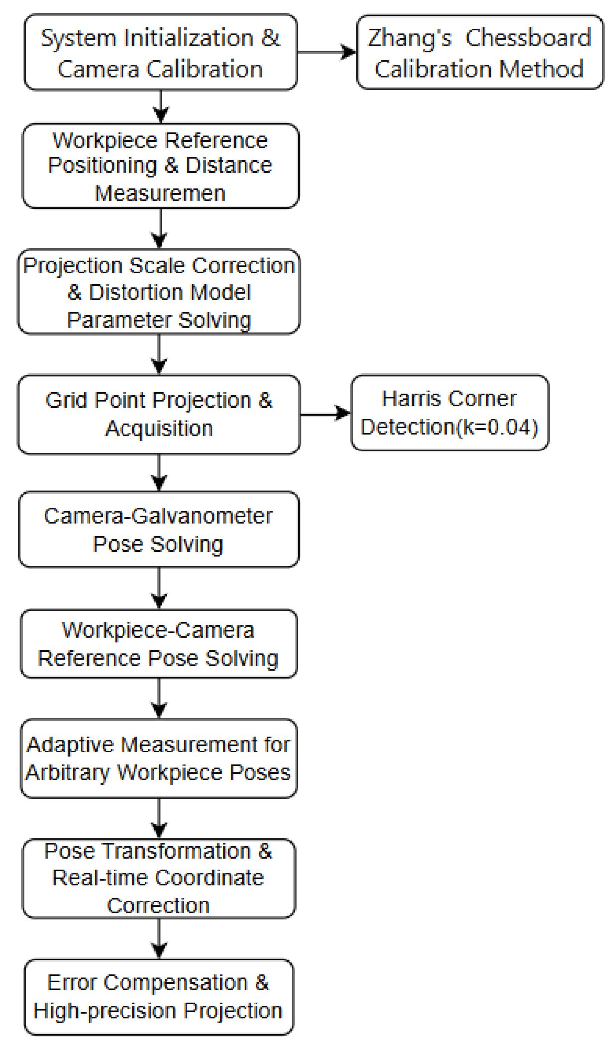
In the laser 3D projection system based on binocular vision, accurately establishing the pose relationships among various components is the core step to achieve accurate projection. The mainstream baseline methods mainly include the traditional monocular vision calibration method and the laser tracker-assisted calibration method. The traditional monocular vision calibration method relies on a planar target to complete hand-eye calibration without distance measurement, but it is susceptible to the lack of depth information. Its average full-range error is approximately 120–180 m, and it cannot adapt to arbitrarily placed workpieces. The laser tracker-assisted calibration method achieves high precision, reaching 30–50 m, but suffers from high equipment cost, cumbersome operation, and low on-site deployment efficiency. This research proposes a pose calibration method combining binocular vision and laser ranging technology. By establishing the reference position calibration, the system can adapt to arbitrary placement of the workpiece within the projection range, finally determine the pose relationship of the workpiece relative to the projection, and complete the precise positioning and projection task. Figure 13 shows the flow chart of multi-coordinate system fusion calibration, which covers the whole process including binocular camera calibration, reference pose calibration, Harris corner detection, multi-coordinate system pose solution, adaptive transformation and error compensation.
Figure 13.
Schematic diagram of the multi-coordinate system fusion calibration process.
2.2.1. Reference Position Calibration
(1) Establishment of Workpiece Reference Position
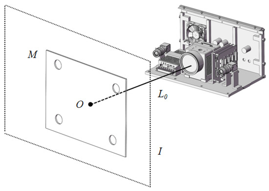
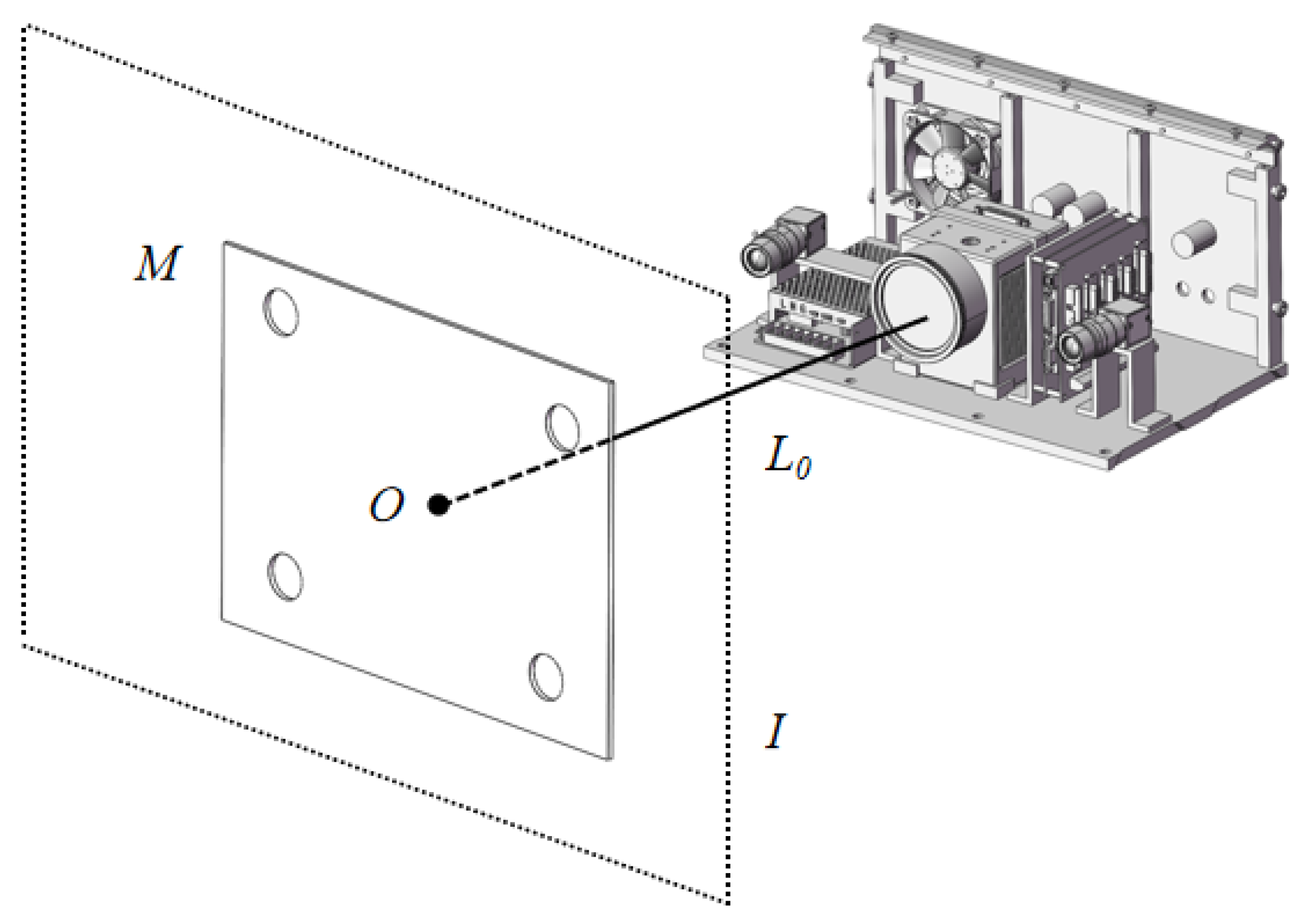
Place the workpiece to be projected within the galvanometer projection range, ensuring its plane remains parallel to the galvanometer projection plane. Use the galvanometer control card to position the galvanometer at the center point (0,0) on the software projection canvas, projecting a characteristic center point. Align the preset center point of the projected workpiece with this projection point as shown in Figure 14. Measure the distance from the workpiece surface to the center point of the Y-axis galvanometer using the laser ranging module, and use this position as the workpiece reference position.
Figure 14.
Schematic diagram of the reference calibration position for the projected workpiece.
(2) Projection Ratio Correction
Control the galvanometer to project a square pattern with a side length of 100 mm at the center point of the software projection canvas. Use the binocular vision subsystem to acquire the camera coordinates of each vertex of the actual projected pattern and convert them into workpiece coordinates, so as to measure the actual projection size. Adjust the scaling ratios and distortion parameters of the X-axis and Y-axis in the software projection canvas coordinate system to make the size and shape of the projected pattern consistent with the set values. The core of this step lies in eliminating the nonlinear distortion and scaling error of the galvanometer system. By comparing the actual side length of the projected square with the theoretical value, iteratively adjust the scaling coefficients. At this point, the relationship between the actual projection size at the workpiece reference position and the software-set size is shown in Equation (1).
In the formula, and represent the horizontal and vertical side lengths of the actual projected square. and represent the horizontal and vertical side lengths of the preset projected square. and are the horizontal and vertical scaling coefficients.
To correct the optical distortion and geometric distortion introduced by galvanometer scanning, a radial even-order polynomial distortion model is adopted in this study to ensure distortion-free projection patterns.The distortion of the galvanometer system is dominated by radial distortion, whose magnitude increases monotonically with the radial distance r from the projection point to the center.Therefore, the even-order terms and are selected as the parameter basis.This setup can accurately describe the actual distortion distribution, while avoiding overfitting and solution instability caused by high-order terms, balancing model accuracy and engineering practicability.The distortion model is shown in Equation (2).
x and y represent the preset projection coordinates. and represent actual corrected projection coordinates. r represent the radial distance from the original projection coordinate point to the projection center. and and are the X-axis distortion parameters of the galvanometer. and are Y-axis distortion parameters of the galvanometer.
To achieve precise correction of the projected pattern, an optimization objective is defined as minimizing the sum of squared deviations between the corrected coordinates and the measured coordinates. A target function is constructed and solved iteratively to obtain the optimal distortion parameters, thereby realizing accurate projection pattern correction. By correcting the projection pattern, the geometric error of the final projection pattern is controlled within an acceptable range.
Under the condition that the workpiece plane is parallel to the projection plane of the galvanometer and the center point remains constant, continuously change the workpiece distance L and measure the size of the projection pattern on the workpiece surface multiple times. The linear relationship between the scaling ratio of the software projection canvas coordinate system and the distance from the workpiece is shown in Equation (3).
(3) Grid Point Projection and 3D Acquisition
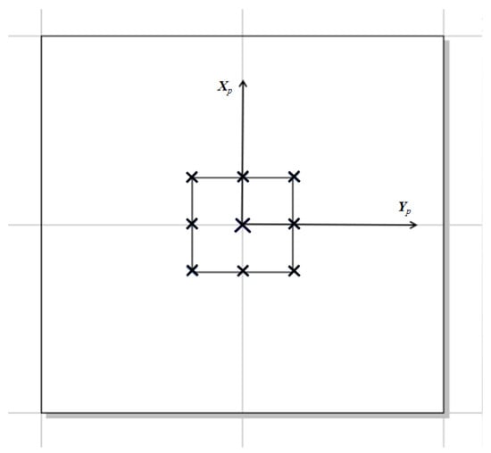
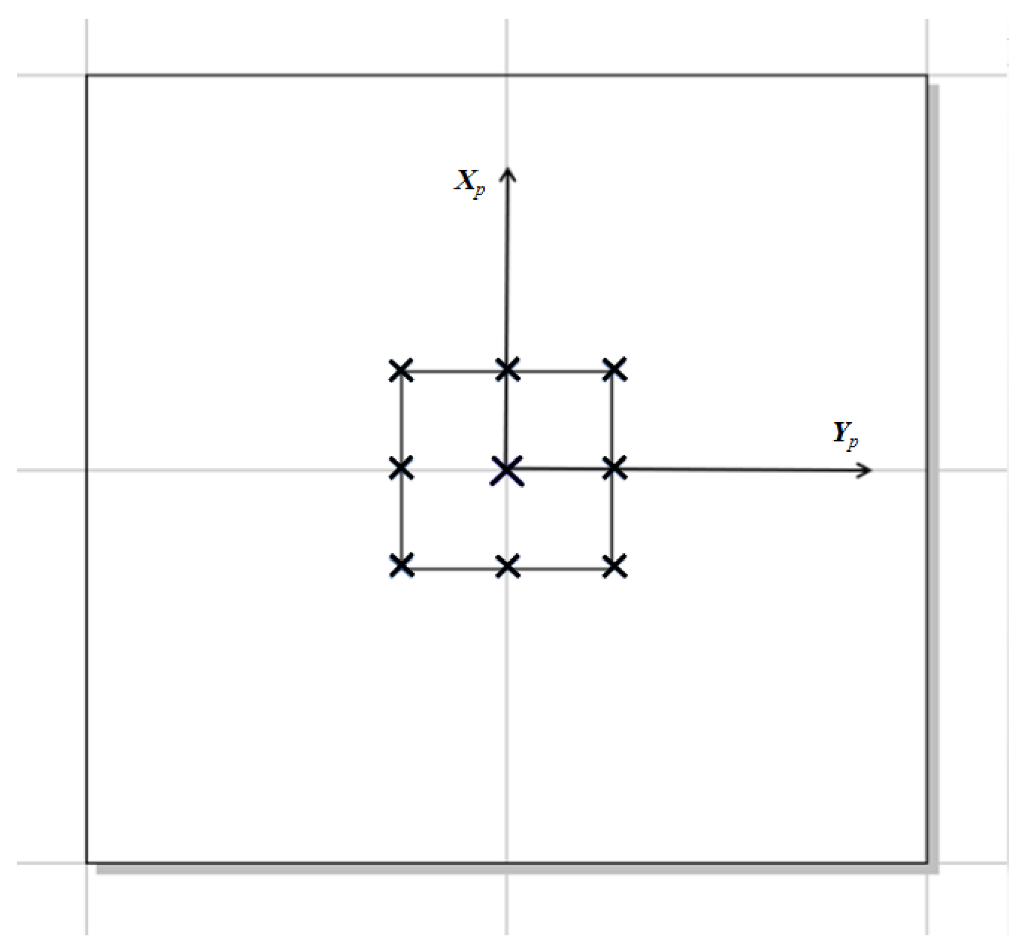
Based on the center point (0,0) of the projection canvas, a symmetrical 2D grid pattern is constructed, and nine feature points including the center point are selected. The galvanometer control card projects these nine feature points in sequence to ensure accurate projection position of each points as shown in Figure 15.
Figure 15.
Schematic diagram of constructing feature points on a projection canvas.
The binocular camera captures workpiece images containing the projected grid points. The Harris corner detection method is used to extract the grid point positions in the images.
For the input image, the Sobel operator is used for gradient convolution in the horizontal and vertical directions. It is shown in Equation (4).
Based on the gradient image, the square of the gradient in the direction of x and y and the product term of the local gradient in the direction of are calculated. Gaussian weighted summation is performed on the three product terms respectively to suppress noise and enhance the influence of the local neighborhood. It is shown in Equation (5).
The autocorrelation matrix describing the second-order statistical characteristics of gray changes in the local neighborhood of the image is constructed for each pixel. It is shown in Equation (6).
To clearly judge whether each pixel in the image is a corner, a corner point response function R needs to be constructed. It is shown in Equation (7).
is the determinant of matrix M, reflecting the anisotropy of local gradient variations. denotes the matrix trace, reflecting the overall intensity of gradient changes. k is an empirical constant used to adjust the sensitivity of the response function. Its value directly affects the stability and accuracy of corner detection. In binocular vision scenarios, it is typically set between 0.04 and 0.06 to effectively distinguish corners from edges and reduce false detections. In this study, the value is set to 0.04.
The corner point response function is designed to capture the unique properties of local gray-level variations in the image, aiming to accurately identify and highlight key feature points in the image. Let the two eigenvalues of the autocorrelation matrix M be and . The eigenvalues of the autocorrelation matrix can be used to describe various regions in the image, as shown in Equation (8).
Therefore, the corner point response function is shown in Equation (9).
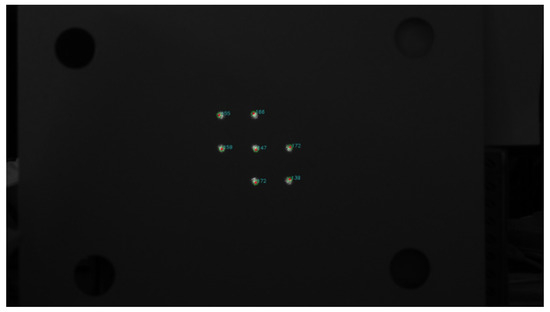
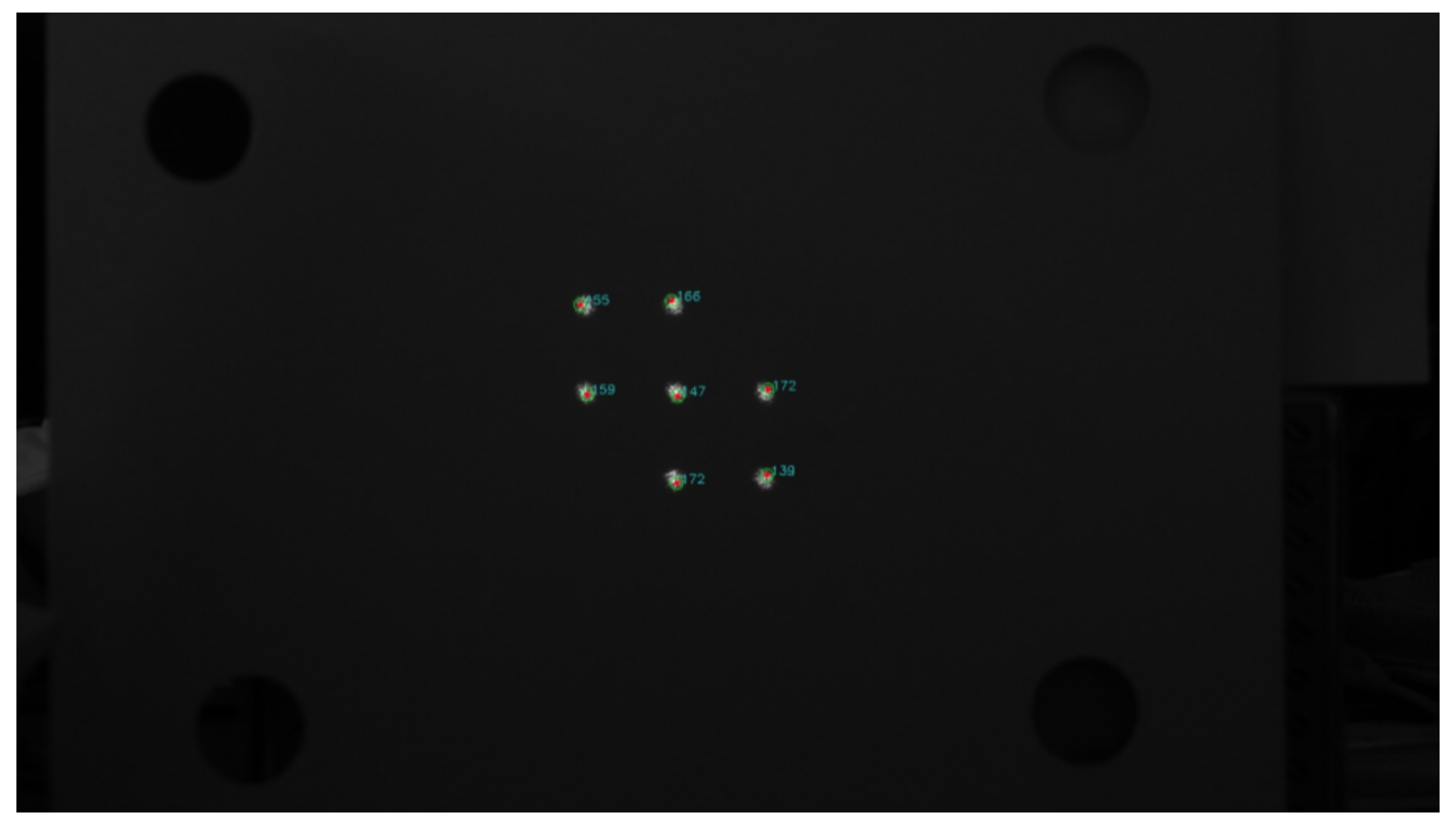
In this study, to accurately locate the projected feature points, a threshold T is set, which is used to filter valid corners and perform non-maximum suppression. It is adaptively determined according to the gradient intensity of the projected light spot and the image noise level, taking 10% 20% of the global maximum value of the corner response function R, which can completely retain the projected feature points while filtering out noise. For each pixel in the image, if R is less than zero, it is regarded as an edge; if the absolute value of R is close to zero or lower than the set threshold, it is judged to be in a flat area; if R exceeds the preset threshold, the pixel is presumed to have significant features, and non-maximum suppression is performed. Therefore, an appropriate threshold can realize automatic corner detection through the corner response function. As shown in Figure 16, the Harris corner detection method is employed to extract grid point positions within a specific frame of an image. The pixel coordinates of the corresponding matching point pairs are obtained at the same time, and combined with the camera parameters, the 3D spatial position of each feature point in the camera coordinate system can be accurately calculated.
Figure 16.
Schematic diagram of feature points extracted using Harris corner detection method.
(4) Pose Establishment of Binocular Camera and Galvanometer System
To solve the reference pose relationship between the galvanometer system and the binocular camera, it is necessary to register the 3D point set of the nine collected feature points in the galvanometer coordinate system with the 3D point set in the camera coordinate system. In this study, the Iterative Closest Point (ICP) algorithm and the optimization technique based on Singular Value Decomposition (SVD) are integrated to improve the accuracy and efficiency of 3D data registration and model fusion. For each feature point in the galvanometer coordinate system point set and each feature point in the camera coordinate system point set, the centroid of the point set is calculated separately, as shown in Equation (10):
The galvanometer coordinate system point set and the camera coordinate system point set are de-centroidized to obtain a new point set. The new point set is as shown in Equation (11).
According to the obtained de-centroid point sets of the galvanometer coordinate system and the camera coordinate system, a covariance matrix is constructed as shown in Equation (12).
Perform singular value decomposition on covariance matrix H as shown in Equation (13).
U and V are orthogonal matrices, and is a diagonal matrix. Consequently, the coarse registration rotation matrix and translation vector can be obtained. The coarse registration transformation matrix is defined as the initial transformation matrix, as shown in Equation (14).
For each feature point in the galvanometer coordinate system point set, identify the point in the camera coordinate system point set with the shortest Euclidean distance and establish a corresponding relationship, as shown in Equation (15).
By constructing the objective function, the aim is to minimize the sum of squared Euclidean distances between corresponding points, as shown in Equation (16).
where k denotes the iteration count with an initial value of 0. By minimizing the objective function, the updated rotation matrix and translation vector are obtained, thereby yielding the pose transformation matrix after one iteration as shown in Equation (17).
The difference between the pose transformation matrix of the current iteration and the previous iteration is expressed as shown in Equation (18).
Set a convergence threshold mm, when , stop iteration and take the current pose transformation matrix as the final registration result to determine the rotation matrix and translation vector between the binocular camera and the galvanometer.
(5) Reference Pose Establishment Between Projected Workpiece and Binocular Camera
To establish the reference pose relationship between the workpiece and the binocular camera, it is essentially to solve the transformation matrix from the workpiece coordinate system to the camera coordinate system. Therefore, the coordinates of the same set of feature points in the two coordinate systems need to be obtained.
By constructing descriptors for each circular feature and setting various matching constraints, the corresponding center feature point pairs of the four circular features are found in the left and right camera images, and their 3D coordinates are obtained. At the same time, according to the 3D model of the workpiece to be projected, a certain feature point is predefined as the origin to establish the workpiece coordinate system, so as to obtain the workpiece coordinates of the four feature points.
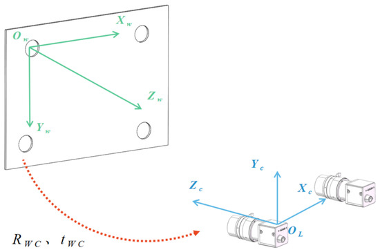
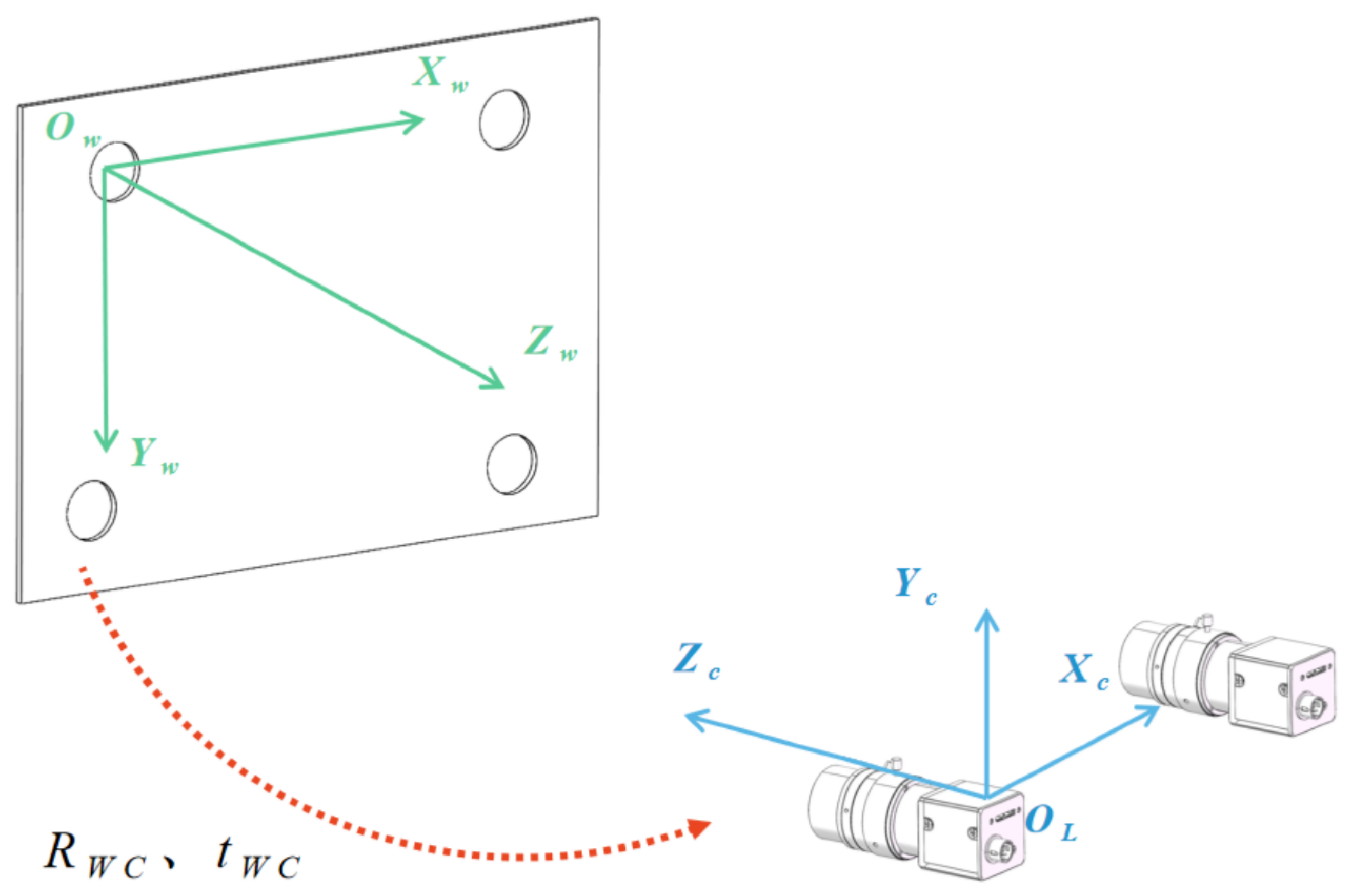
Keep the workpiece position where the workpiece plane is parallel to the galvanometer projection plane when the pose between the binocular camera and the galvanometer coordinate system is established, as shown in Figure 17. Take the center of the circular feature in the upper left corner as the origin to establish the workpiece coordinate system. Thus, the coordinate information of the same set of feature points in two different coordinate systems is obtained, and the transformation matrix can be solved based on these information.
Figure 17.
Schematic diagram of workpiece coordinate system establishment.
The Perspective-n-Point (PnP) algorithm is applied to accurately calculate the attitude and pose information of the workpiece in the camera coordinate system. The optimal rotation matrix and translation vector are obtained by minimizing the reprojection error, so as to determine the pose relationship between the workpiece and the binocular camera. The expression is shown in Equation (19).
At this time, the obtained rotation matrix and translation vector are the pose relationship of the workpiece relative to the binocular camera at the reference position.
2.2.2. Adaptive Pose Transformation Solution
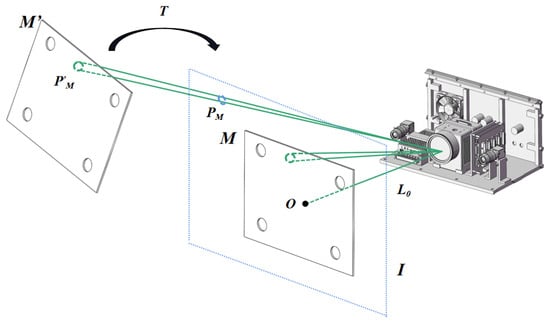
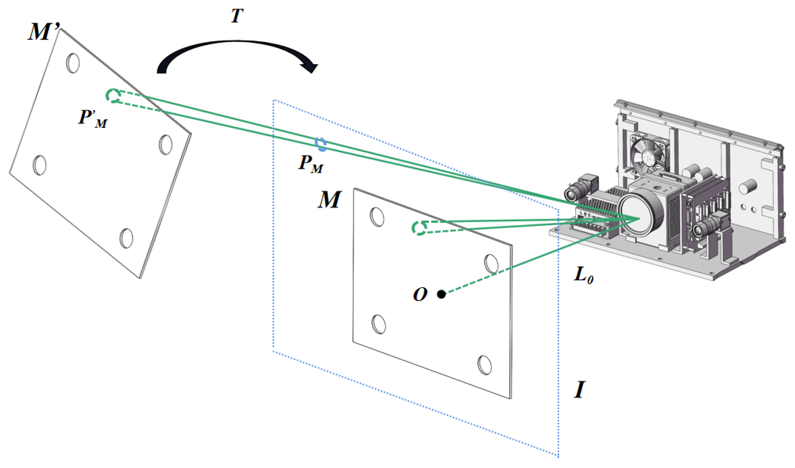
After the precise calibration of the reference pose, an accurate proportional relationship between the software projection canvas and the workpiece projection size and the correspondence of the center points are constructed. The fixed pose between the binocular camera and the projection system, as well as the relative reference pose relationship of the workpiece under the set reference, are established. As shown in Figure 18, when the workpiece is arbitrarily positioned within the projection range at location M’, it is necessary to re-establish the pose relationship between the projected workpiece and the binocular camera. By comparing with the pose relationship of the workpiece reference position, solving the transformation matrix T of the workpiece relative to the reference position, the 3D projection point set of the workpiece at the new position can be converted to that at the reference position.
Figure 18.
Schematic diagram of adaptive pose calibration.
At the workpiece reference position, the reference scaling factor obtained by Equation (3) has calibrated the reference projection size to the size on the projection canvas as 1:1. Therefore, the projection point set at this time can be directly arranged on the software projection canvas. The relational expression is shown in Equation (20).
represents a 2D point set projected onto the software canvas and is the reference scaling factor.
Thus, through the conversion from the 3D projection point set of the workpiece to the 2D projection point set on the software projection canvas, the adaptive pose calibration when the projected workpiece is placed under any pose within the projection range is completed. Inputting the 2D point set of the preset projection to the software projection canvas can complete the laser 3D projection and measurement at any position.
3. Experiments and Accuracy Analysis
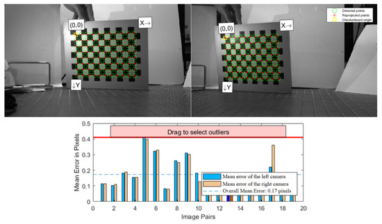
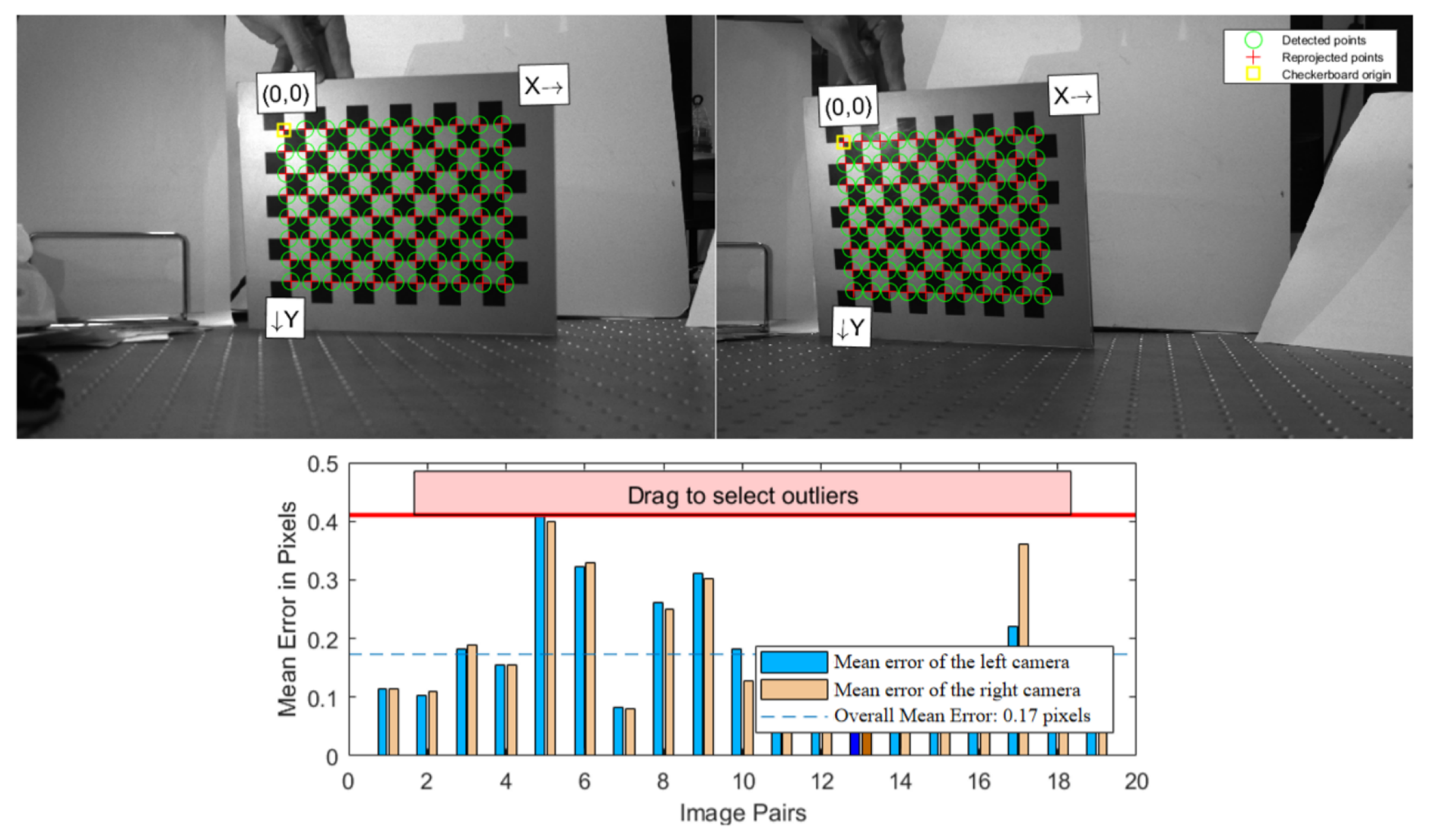
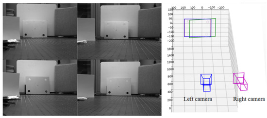
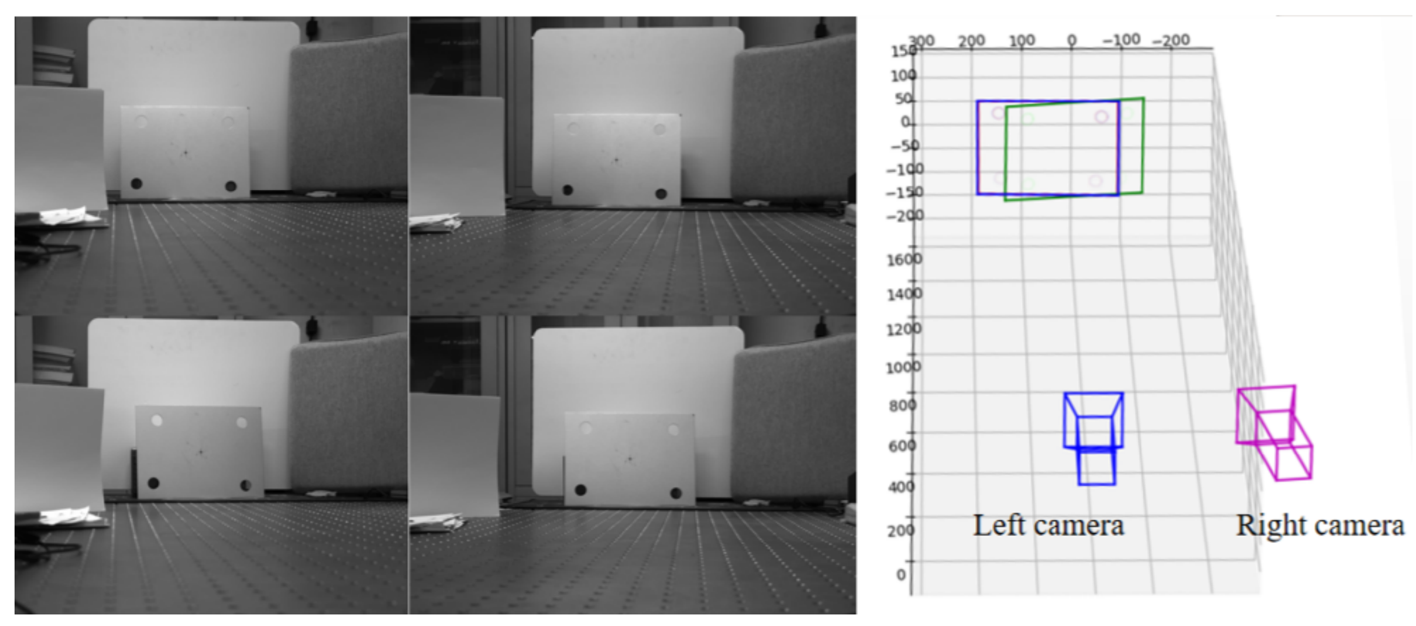
Before system calibration, the binocular camera must be calibrated first. Based on the analysis of camera calibration, the Zhang’s chessboard method in the planar calibration method is selected as the experimental calibration scheme of this study. A high-precision chessboard is placed within the common field of view of the binocular cameras. To conduct calibration accuracy testing, five typical positions—1.5 m, 1.8 m, 2.0 m, 2.2 m, and 2.5 m—are selected within the system’s working range of 1.5 m to 2.5 m, ensuring that both left and right cameras can clearly capture the complete chessboard pattern. At each position, 20 sets of chessboard images with different poses are acquired simultaneously. Based on the principle analysis of the binocular vision subsystem, a sub-pixel corner detection algorithm is employed to extract the 2D pixel coordinates of the inner corners of the chessboard. The corresponding relationships between corners in the binocular images are established to obtain the intrinsic, extrinsic, and stereo parameters of the binocular cameras, which are used for subsequent system calibration. The reprojection error shows a slow increasing trend with the increase in working distance. As shown in Figure 19, at 2.5 m (the maximum working distance of the system), which is the position with the largest error, the average calibration error is 0.17 pixels, approximately 1.1 m, meeting the experimental requirements.
Figure 19.
Schematic diagram of calibration results and error verification for binocular camera system.
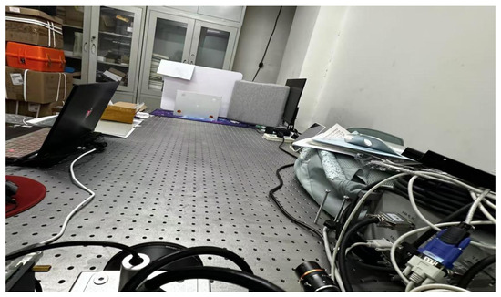
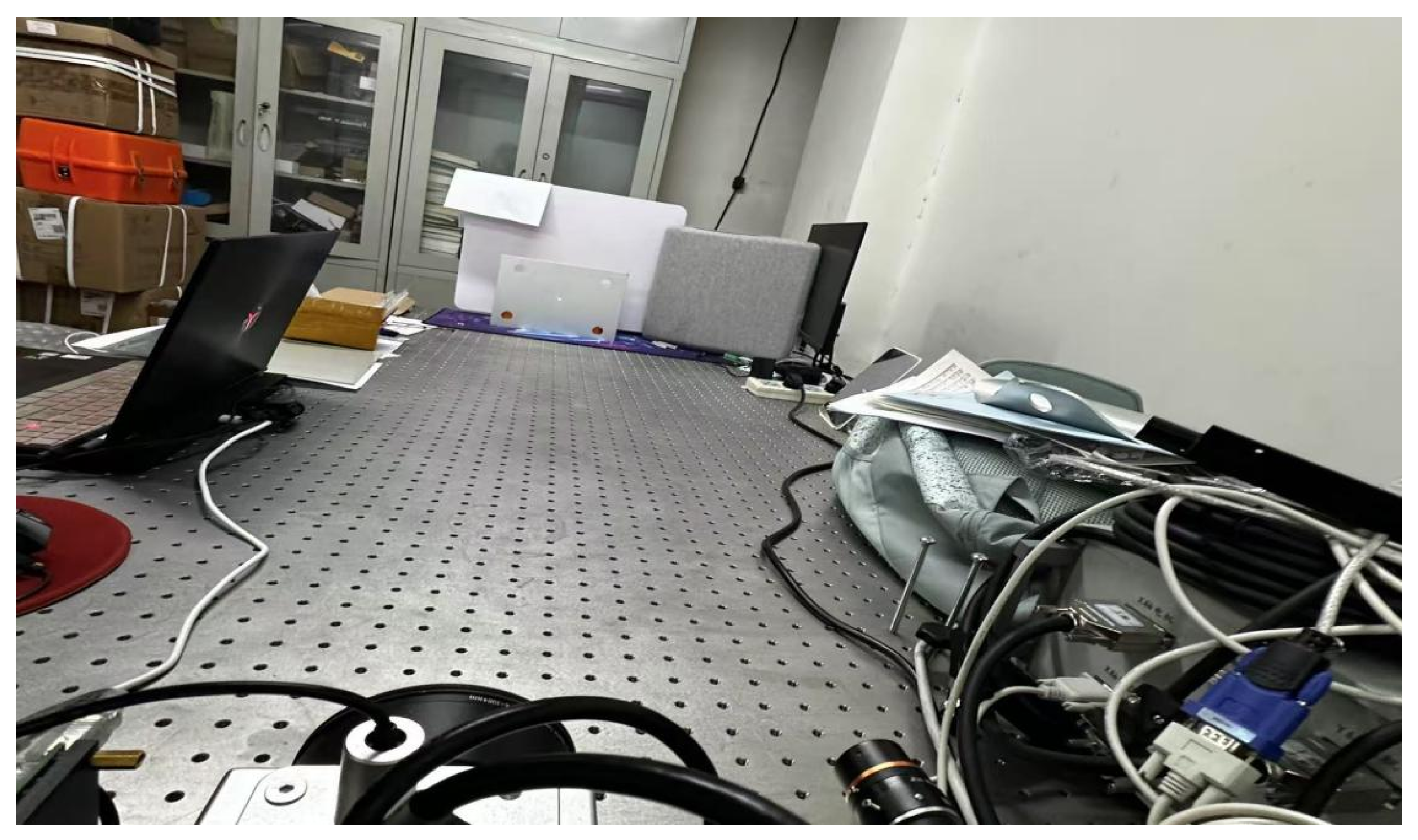
As shown in Figure 20, the workpiece to be projected is placed at a distance of 1.5–2.5 m from the projection system within the projection range. Through feature recognition and localization of the workpiece by the binocular camera, the pose relationship between the workpiece and the binocular subsystem at this position is established, and the pose calibration of the workpiece at the reference position is completed.
Figure 20.
Schematic diagram of practical operation for establishing workpiece reference position.
According to the actual operation requirements, adjust the position and attitude of the workpiece and place it in a new position. Repeat the above binocular camera recognition and positioning steps to obtain the 3D information of the feature round holes on the workpiece at the new position. Combined with the relative position of the feature round holes on the workpiece and the actual size of the workpiece, the ICP algorithm is used to obtain the pose transformation between the corresponding feature round holes, so as to solve the pose transformation between the newly placed workpiece and the reference workpiece. As shown in Figure 21, the relative pose change of the workpiece in 3D space is fitted through the obtained 3D information of the feature round holes.
Figure 21.
Schematic diagram of 3D fitting model for adaptive pose calibration Relations.
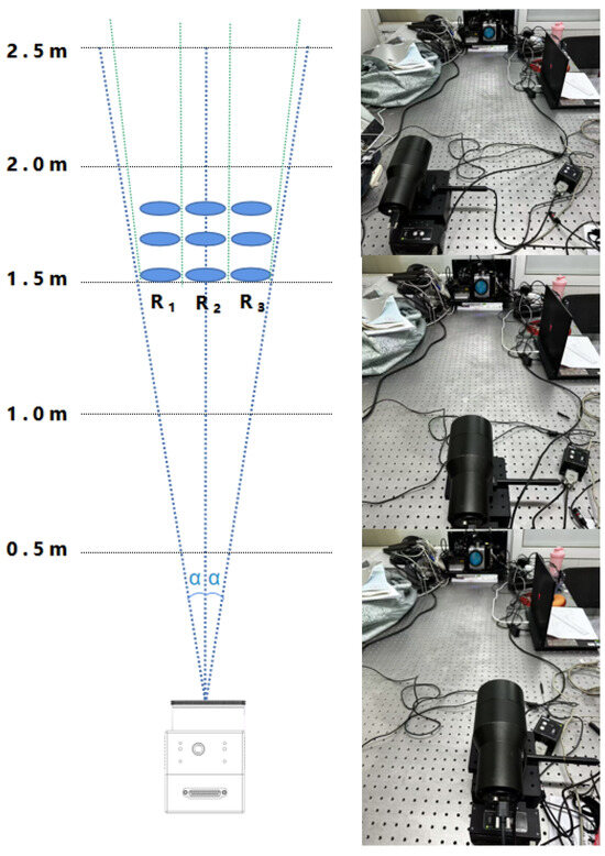
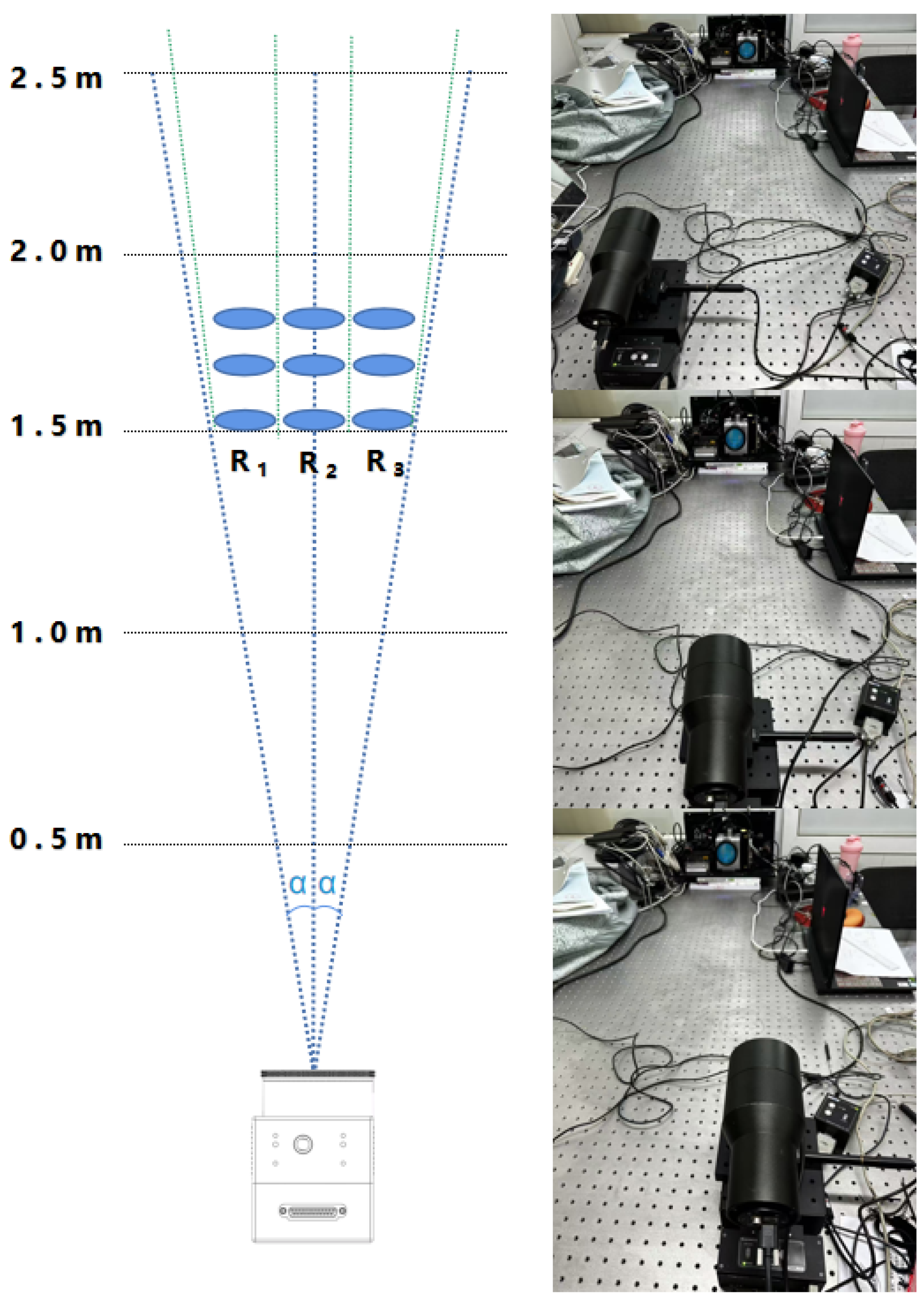
The error verification instrument is placed in the three regions at different distances, totaling 18 measurement points. The laser is controlled to project a laser spot in a fixed direction, ensuring the spot enters the target head and appears in the camera image. The current position of the translation stage is taken as the reference measurement position; the image is captured, and the pixel coordinates of the spot in the image are output via corner detection. To verify the calibration accuracy, a repetitive projection experiment is required. In this study, the spatial position deviation of the projected point is adopted as the accuracy evaluation index. As shown in Figure 22, within the working distance of 1.5–2.5 m and the maximum projection scanning angle of ±15°, three regions , and are divided, and further divided into six groups of measurement distances. The actual working distances are measured using the ranging module. The error verification instrument is placed in the three regions at different distances, totaling 18 measurement points. The laser is controlled to project a laser spot in a fixed direction, ensuring the spot enters the target head and appears in the camera image. The current position of the translation stage is taken as the reference measurement position; the image is captured, and the pixel coordinates of the spot in the image are output via corner detection. The translation stage is then controlled to step a certain distance from the reference position in one direction and return. The image upon returning to the reference position is captured, and the spot pixel coordinates are detected. This process is repeated for fifty repeatability measurements.
Figure 22.
Schematic diagram of the experimental area within the working range of the laser projection system.
Using the pre-calibrated pixel-to-length ratio, the average deviation of the fifty measurements in the region is calculated, completing the accuracy repeatability experiments for the three regions at each distance. The experimental results are shown in Table 1. The results show that the maximum calibration error of the system is 45.5 m, and the error increases with increasing distance, with the maximum value occurring at the farthest working distance of 2.5 m. The self-calibration error of the binocular camera at 2.5 m is 1.1 m, which is much smaller than the system error and does not affect the overall accuracy. Limited by the field of view of the binocular camera, complete images of the workpiece cannot be captured at distances less than 1.5 m, and short-distance operation is not required in practical engineering applications. Therefore, 1.5–2.5 m is defined as the effective working range of the system.
Table 1.
Results of calibration repeatability deviation in three set regions at different distances using an error verification instrument.
To verify the long-term stability of the system, continuous operation tests were conducted under typical working conditions for two hours. Following the aforementioned experimental method, the repeatability deviation data of the three regions at 2.5 m were collected every 15 min. The results are shown in Table 2. The maximum drift of the projection repeatability deviation is only 0.1 m, indicating that the system can maintain high accuracy even during long-term continuous operation.
Table 2.
Long-term continuous working stability test results of the system.
To fully verify the adaptive calibration capability of the proposed method under arbitrary workpiece placement, the workpiece was placed in region at 2.5 m with different tilt angles to simulate extreme placement conditions such as non-flat and non-parallel surfaces in practical scenarios. The experimental results are shown in Table 3. Within the combined tilt range of ±15° along the workpiece X-Y axes, the maximum drift of the projection repeatability deviation is 0.2 m. This sufficiently proves the effectiveness and reliability of the adaptive calibration under extreme tilt conditions of the workpiece.
Table 3.
Adaptive test results of the system under arbitrary workpiece placement.
4. Conclusions
This study proposes a high-precision calibration method for the laser 3D projection system based on pose relationship. By fusing binocular vision and laser ranging technology, a unified multi-coordinate calibration framework integrating the camera, galvanometer, and workpiece is constructed, achieving adaptive high-precision projection calibration for workpieces in arbitrary poses. Compared with existing methods, the main technical contributions and innovations of this paper are reflected in three aspects. First, a tightly coupled multi-sensor multi-coordinate fusion system is established. By solving the transformation relationships of camera-galvanometer pose and workpiece-camera pose in a unified manner, the error accumulation caused by independent calibration is effectively suppressed, and the overall accuracy and stability of the system are improved. Second, an adaptive pose transformation solution strategy for arbitrarily placed workpieces is proposed. Fast online calibration within the full working range can be completed with one single reference position calibration, which eliminates the dependence on special tooling and precise positioning and greatly improves on-site flexibility. Third, the key parameter design for galvanometer distortion correction and feature extraction is optimized. The parameter selection basis and solution method of the polynomial distortion model are clarified, and the setting criteria of the empirical constant k and threshold T in Harris corner detection are provided, making the entire calibration process more rigorous and reproducible. Experimental results show that within the effective working range of 1.5–2.5 m, the maximum system calibration error is 45.5 m. The maximum error of the binocular camera at the farthest distance of 2.5 m is approximately 1.1 m. The accuracy is significantly better than the traditional monocular vision method and comparable to the laser tracker method, while exhibiting greater advantages in on-site applicability, operational convenience, and low cost. Through tests under two challenging working conditions: continuous operation and large-angle tilting, the proposed method is proven to have excellent repeatability and stability, and can realize adaptive high-precision calibration for arbitrarily placed workpieces in non-ideal and complex scenarios, meeting the high-precision requirements of precision machining and assembly of large-scale aerospace components. Limited by the field of view of the binocular camera, complete workpiece images cannot be collected at distances less than 1.5 m. In practical assembly scenarios, workpieces are usually placed beyond 1.5 m, so 1.5–2.5 m can cover the entire effective working range. In the future, deep learning can be combined to optimize the feature detection algorithm, further improving the calibration robustness under weak texture, occlusion, and complex illumination environments.
Author Contributions
Conceptualization, D.L., X.L. and Y.L.; methodology, Y.L.; software, Y.L.; validation, Y.L.; formal analysis, Y.L.; investigation, Y.L., Z.Z., X.W. and T.C.; resources, D.L. and X.L.; data curation, Y.L.; writing—original draft preparation, Y.L.; writing—review and editing, Y.L.; visualization, Y.L.; supervision, D.L. and X.L.; project administration, D.L. and X.L.; funding acquisition, D.L. and X.L. All authors have read and agreed to the published version of the manuscript.
Funding
This research received no external funding.
Data Availability Statement
No new data were generated or analysed in support of this research. All data that support the findings of this study are included within the article.
Conflicts of Interest
The authors declare no conflicts of interest.
References
- Rueb, K.D.; Wieczorek, J.P. Collimator for Laser Projector. U.S. Patent 19970814669, 18 April 2000. [Google Scholar]
- Wang, Y.; He, C. Design of 360-degree Panoramic Display System Based on 3D Laser Scanning Data. Laser J. 2023, 44, 162–166. [Google Scholar]
- Guo, S.; Feng, Y.; He, S.; Huang, X.; Si, Y. Novel Post Heat Treatment Strategy to Obtain Laser 3D Printed IN718 Superalloy with High Strength and High Toughness. Mater. Res. Appl. 2022, 16, 1017–1023. [Google Scholar]
- Zhang, J. Study on Surface Quality of Titanium Alloy Parts in Laser Repair Milling. Master’s Thesis, Civil Aviation University of China, Tianjin, China, 2021. [Google Scholar]
- Hou, M.; Wu, K.; Zhang, H.; Gu, C.; Duan, J. Research on Discontinuous Scanning Method Based on Correlated Double Sampling Detection. Chin. J. Lasers 2024, 51, 56–67. [Google Scholar]
- Liu, C.; Wu, J.; Gu, Y.; Xie, L.; Wu, G. Binocular vision-based guidance for robotic assembly of prefabricated components. Autom. Constr. 2025, 172, 106065. [Google Scholar] [CrossRef] [Scilit]
- Maffei, A.; Dalle Mura, M.; Monetti, F.M.; Boffa, E. Dynamic mixed reality assembly guidance using optical recognition methods. Appl. Sci. 2023, 13, 1760. [Google Scholar] [CrossRef] [Scilit]
- Li, Q.; Xu, M. Design of Industrial Robot Tire Assembly Line Based on 3D Vision Guidance. Automob. Manuf. 2024, 6, 51–54. [Google Scholar]
- Xu, Z.; Duan, X.; Zhu, Y.; Zhang, D. On galvanometer laser projection positioning to layups of large composite material. Machines 2023, 11, 215. [Google Scholar] [CrossRef] [Scilit]
- Zheng, W.; Bi, X.; Yang, F.; Wei, J.; Jie, L. Research on high-precision measurement technology for aircraft large-scale tooling assembly. J. Phys. Conf. Ser. 2025, 2955, 012034. [Google Scholar] [CrossRef] [Scilit]
- Liu, C.; Wu, J.; Jiang, X.; Gu, Y.; Xie, L.; Huang, Z. Automatic assembly of prefabricated components based on vision-guided robot. Autom. Constr. 2024, 162, 105385. [Google Scholar] [CrossRef] [Scilit]
- Zhang, Y.; Gao, P.; Wang, Z.; He, Q. Research on status monitoring and positioning compensation system for digital twin of parallel robots. Sci. Rep. 2025, 15, 7432. [Google Scholar] [CrossRef] [Scilit] [PubMed]
- Amroune, A.; Cuillière, J.C.; François, V. Automated lofting-based reconstruction of CAD models from 3D topology optimization results. Comput.-Aided Des. 2022, 145, 103183. [Google Scholar] [CrossRef] [Scilit]
- Bruehl, M. Laser template projection for composite assembly. Reinf. Plast. 2005, 49, 56–57. [Google Scholar] [CrossRef] [Scilit]
- Sivertsen, C.G. Laser Projection System Projecting Content Based on Information Collected from Nearby Targets. U.S. Patent 9,292,757, 22 March 2016. [Google Scholar]
- Ren, Y.; Zhu, J.; Yang, X.; Ye, S. Method of robot calibration based on laser tracker. Chin. J. Mech. Eng. 2007, 43, 195–200. [Google Scholar] [CrossRef] [Scilit]
- Hou, M.; Chen, Y.; Shi, Z.; Li, Z. Self-calibration Method of Laser Scanning Projection System Combined with Monocular Vision. Acta Photonica Sin. 2021, 50, 134. [Google Scholar]

Disclaimer/Publisher’s Note: The statements, opinions and data contained in all publications are solely those of the individual author(s) and contributor(s) and not of MDPI and/or the editor(s). MDPI and/or the editor(s) disclaim responsibility for any injury to people or property resulting from any ideas, methods, instructions or products referred to in the content. |
© 2026 by the authors. Licensee MDPI, Basel, Switzerland. This article is an open access article distributed under the terms and conditions of the Creative Commons Attribution (CC BY) license.