


Abstract
Rydberg-atom electric-field sensors have emerged as an important research direction in quantum precision measurement, owing to their intrinsic SI traceability, noninvasive measurement capability, and wide frequency tunability. However, under free-space conditions, the geometric divergence of microwaves (MWs) limits the practical detection performance of the system. In this work, we propose and experimentally demonstrate a metasurface-assisted Rydberg-atom hybrid sensor. Through introducing wavefront shaping of the incident microwave field with a metasurface (MS), electric-field enhancement in the atomic sensing region is achieved. Without altering the intrinsic sensitivity of the Rydberg-atom sensor, the equivalent sensitivity of the hybrid sensor is improved to . This scheme provides a new route toward high-sensitivity, integrated quantum sensing of the microwave electric field.
1. Introduction
Quantum sensing based on Rydberg atoms has attracted significant attention in recent years for applications such as radar detection [1], wireless communications [2,3], imaging [4,5], and high-voltage discharge diagnostics [6,7,8], due to its intrinsic traceability of SI [9], noninvasive measurement capability, and wide frequency tunability [10,11]. Recent studies have shown that the sensitivity of Rydberg-atom sensors can achieve a sub- level [12,13,14]. Under free-space conditions, the geometric divergence of MW propagation leads to spatial spreading of the energy, reducing the field strength in the atomic sensing region and constituting a major factor that limits sensor performance [15,16].
Current efforts to improve the performance of Rydberg-atom sensors have focused primarily on reducing system noise [17,18,19], modulation and demodulation techniques [20,21], and exploiting critical enhancement [22], while the spatial shaping of electromagnetic fields at the front end of the sensing system has received relatively limited attention. MS are artificial structures composed of subwavelength unit cells. By tailoring the propagation characteristics of electromagnetic waves, they can realize functionalities such as beam shaping and electric-field enhancement [23,24,25,26,27,28]. Introducing the MS into the Rydberg-atom sensing system enhances the electric-field strength in the atomic sensing region through spatial wavefront engineering and improves the equivalent sensitivity at the system-level.
In this work, we propose and experimentally validate a hybrid sensing scheme that combines the MS with the Rydberg-atom. Through spatial field measurements, sensitivity calibration, and electromagnetic simulations, we systematically investigate the wavefront shaping of the MS and its impact on the equivalent sensitivity of the hybrid sensing system. The results show that, without altering the atomic sensing mechanism, the proposed scheme can effectively reduce the equivalent minimum detectable electric field of the system for external MW fields, thereby providing an efficient system-level enhancement strategy for free-space quantum sensing.
2. Metasurface–Rydberg-Atom Hybrid Sensor
2.1. Principle of Rydberg-Atom Electric-Field Sensing
Rydberg-atom electric-field measurements are typically based on electromagnetically induced transparency (EIT) in a ladder-type three-level atomic system. A probe laser and a coupling laser drive the atoms to a Rydberg state, giving rise to an EIT transparency window in the probe transmission spectrum. When an external MW field near-resonantly couples two Rydberg states, the EIT resonance undergoes Autler–Townes (AT) splitting. The splitting separation is directly related to the amplitude of the MW electric field E according to [29]
where ℏ is the reduced Planck constant and is the transition dipole moment between adjacent Rydberg states.
2.2. Wavefront Shaping in the Hybrid Sensor
The proposed hybrid sensor combines the MS with the Rydberg-atom system. The MS is placed in front of the atomic sensing region to tailor the incident MW wavefront. In free space, the incident MW electric field radiated by a horn antenna can be expressed as
where and denote the amplitude and phase distributions of the incident electric field, respectively. The MS introduces a position-dependent effective phase delay to reconstruct the transmitted MW wavefront, so that a designed spatial energy distribution is formed at the location of the atomic vapor cell [30,31]. This process is essentially a spatial redistribution of the incident MW energy, which results in an enhanced electric-field amplitude in the atomic sensing region.
2.3. Definition of Equivalent Sensitivity
When evaluating system performance, it is necessary to distinguish between the intrinsic sensitivity of the atomic sensor and the equivalent sensitivity of the hybrid sensor. The intrinsic sensitivity of the atomic sensor, denoted by , characterizes its minimum resolvable electric-field strength in the sensing region. After the MS is introduced, the electric-field strength in the atomic sensing region is enhanced compared with that without the MS. The field-enhancement factor is defined as
where and denote the electric-field strength in the atomic sensing region with and without the MS, respectively, under the same MW source power. The equivalent sensitivity of the hybrid sensor can be expressed as
3. Metasurface Structure
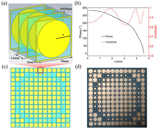
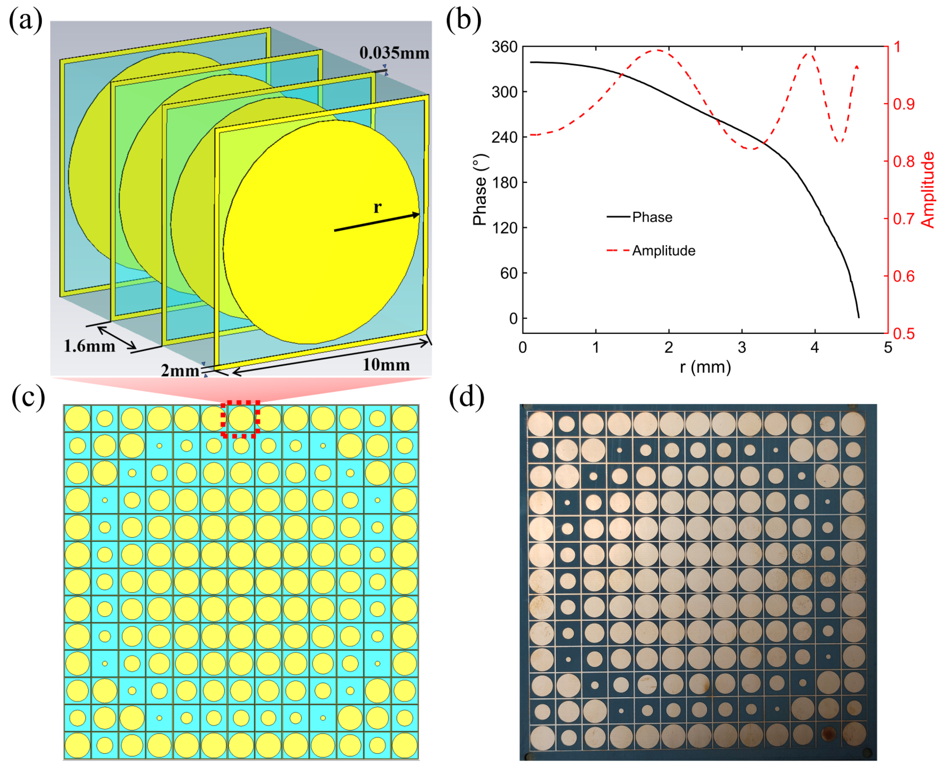
As shown in Figure 1a, the MS unit cell employed in this work consists of four identical metallic layers alternately stacked with three dielectric layers. The electromagnetic response of the MS unit cell was analyzed using the CST electromagnetic simulation software with the Frequency Domain Solver. In the unit-cell simulation, periodic boundary conditions were applied along the x and y directions to represent the response of the unit cell in an infinite periodic array, while Floquet ports were used along the z direction as the excitation. The incident wave was normally incident and linearly polarized. The dielectric material is F4B, with a relative permittivity of 2.65 and a loss tangent of 0.002; the unit cell is a square, with a period of 10 mm; and each dielectric layer has a thickness of 1.6 mm. Each metallic layer has a thickness of 0.035 mm and consists of an outer square ring and an inner solid circular patch. The transmission phase is controlled by tuning the radius r of the circular patch. Figure 1b shows the transmission amplitude and phase of the unit cell as functions of r. As r varies, the transmission phase covers a range of approximately , while the transmission amplitude remains above 0.8.
Figure 1.
(a) Schematic of the MS unit cell. (b) Transmission amplitude and phase of the unit cell versus the radius r of the circular metallic patch. (c,d) Schematic of the MS and photograph of the fabricated sample.
Based on the phase response of the unit cell, a target phase profile is constructed by spatially arranging cells with different geometric parameters, thereby forming the complete MS. Figure 1c and Figure 1d present the schematic layout and a photograph of the MS, respectively. According to the fabrication inspection results, the main manufacturing tolerances of the MS include a thickness tolerance of ±0.15 mm for the F4B substrate, a machining tolerance of ±0.076 mm for the metallic parts, and a machining tolerance of ±0.05 mm for the nonmetallic parts.
To evaluate the regulating effect of the MS on the incident microwave field under free-space conditions, a three dimensional full-band electromagnetic simulation model including the horn antenna and the complete MS was established. In the simulation model, the horn antenna was a standard-gain horn antenna. The MS consisted of 13 × 13 unit cells, with an overall size of 130 mm × 130 mm. In the geometric arrangement, the MS was placed 32 mm in front of the horn aperture, and their central axes were kept aligned. In the full-structure simulation, the boundaries of the computational domain were set to open to represent free-space propagation conditions. The horn antenna was excited by a waveguide port.
4. Experimental Setup
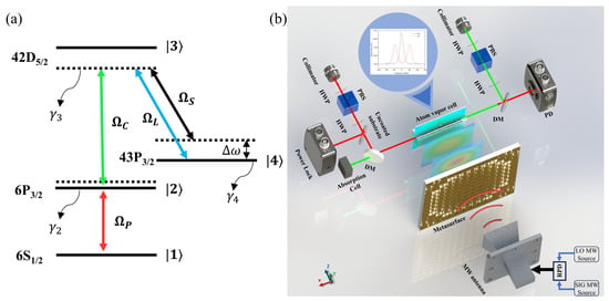
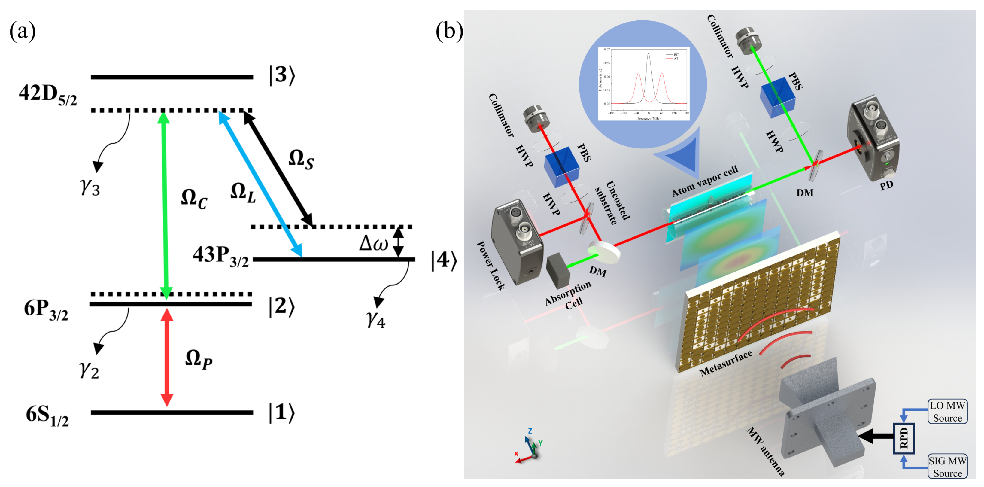
As shown in Figure 2a, the experiment uses a cesium ladder-type three-level EIT system. A probe laser at 852 nm drives the transition from to , while a coupling laser at 510 nm excites the atoms to the Rydberg state. In this configuration, an EIT transparency window appears in the probe transmission spectrum. To implement superheterodyne detection, the local oscillator (LO) and signal (SIG) MW frequencies are set to 9.94357 GHz and 9.94371 GHz, respectively. Both frequencies are close to the to Rydberg transition, producing an intermediate frequency of 140 kHz.
Figure 2.
Overview of the experimental setup. (a) Energy-level diagram of the Rydberg-atom system. The states , , and the Rydberg state are resonantly coupled by the probe and coupling fields, respectively. The LO MW resonantly drives the transition, while the SIG MW has a frequency offset relative to the LO MW. States () have decay rates . (b) Schematic of the hybrid sensor. HWP: half-wave plate; PBS: polarizing beam splitter; DM: dichroic mirror; PD: photodiode; MW antenna: microwave antenna; RPD: two-way resistive power divider.
The experimental setup is shown in Figure 2b. The probe and coupling beams are collimated, and their polarization and power are carefully controlled before they counter-propagate through a cesium vapor cell with dimensions of . A fraction of the probe power is picked off by an uncoated substrate for power stabilization. In the experiment, the probe beam has a power of 50 W and a Gaussian beam diameter of 310 m, while the coupling beam has a power of and a diameter of 410 m.
The MW system consists of a SIG MW source, an LO MW source, a resistive power divider (RPD), and a standard-gain horn antenna (HD-100SGAH10N). The LO and SIG MW signals are combined by the RPD and fed into the same horn antenna, which radiates the MW into free space to interact with the atoms.
Two configurations are used for comparison. In the configuration without the MS, the MW field directly illuminates the atomic vapor cell. In the MS configuration, the MS is placed 32 mm in front of the horn antenna to tailor the MW wavefront. Except for the presence or absence of the MS, all experimental parameters and the overall geometry are kept identical to ensure a valid comparison.
5. MW Field Focusing and Enhancement
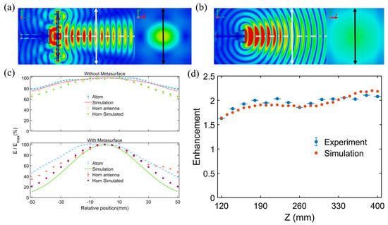
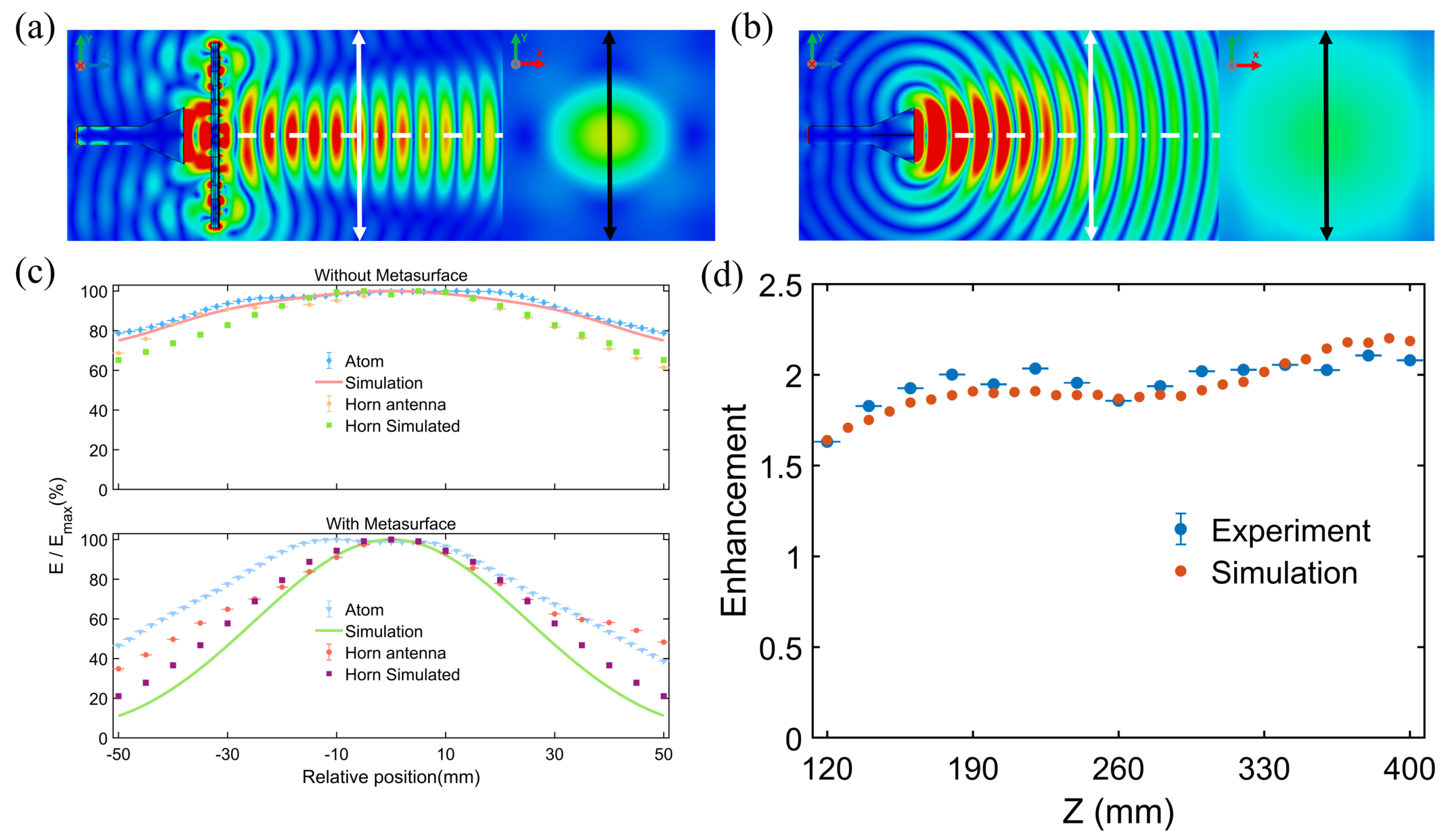
Figure 3a and Figure 3b present the results of the electromagnetic simulation with and without the MS, respectively. Figure 3a shows the electric-field distributions in the plane and in the plane located 120 mm from the MS when the MS is introduced, while Figure 3b shows the corresponding electric-field distributions without the MS. The simulation results indicate that the introduction of the MS modifies the spatial distribution of the MW field, causing the electric field to exhibit a pronounced focusing effect in the atomic sensing region.
Figure 3.
Electric−field strength distributions with (a) and without (b) MS; (c) electromagnetic simulation and experimental measurements with atoms and standard antenna of electric-field strength along the y-axis; (d) enhancement factor at different distances along the z-axis.
To characterize the microwave electric-field distribution in free space, scanning measurements were carried out under both the “with MS” and “without MS” configurations. In the “with MS” configuration, the horn antenna and the MS were mounted together on the translation stage and moved synchronously; in the “without MS” configuration, only the horn antenna was mounted on the translation stage and moved. Throughout the measurement process, the positions of the atomic vapor cell and the optical system were kept fixed, while the microwave source power and the optical detection conditions remained unchanged. In addition, the central axes of the horn antenna, the MS, and the atomic vapor cell were aligned as carefully as possible in order to minimize additional alignment errors.
The scanning step size of the translation stage was set to 2 mm, and the one-way positioning accuracy of the one-dimensional translation stage was . This positioning error is much smaller than the scanning step sizes, and therefore its influence on the measurement results can be neglected. The electric-field strength at each sampling position was obtained from the measured AT-splitting interval of the Rydberg atoms. To reduce the influence of random noise and to evaluate the uncertainty of repeated measurements, each position was measured three times, and the average value was taken as the final result. The error bars in the figure represent the standard deviation of the three repeated measurements.
Figure 3c shows the one-dimensional distribution of the electric field within the central region of the plane over a range of mm along the y-axis, where the results obtained from atomic detection, antenna reception, and electromagnetic simulation were all self-normalized. The results show that, without the MS, the electric-field distribution remains relatively smooth, with no obvious focusing observed. After the MS is introduced, the field-strength distribution within the detection plane changes significantly, and the MW energy is redistributed in space, forming a pronounced focusing region. The results obtained by the three methods show good overall agreement in their variation trends, although some discrepancies remain between the experimental and simulated results, which may be attributed to measurement uncertainty and MW scattering around the vapor cell.
By varying the detection distance along the propagation direction (the z-axis), as shown in Figure 3d, the electric-field strength with the MS remains consistently higher than that without the MS over the tested range. This result indicates that the MS spatially modulates the incident microwave field through wavefront shaping, thereby achieving focusing and enhancement.
6. Equivalent Sensitivity Enhancement of the Hybrid Sensor
Before evaluating the performance of the MS–Rydberg-atom hybrid sensor, the intrinsic sensitivity of the Rydberg-atom sensor was measured. An atomic superheterodyne detection scheme was adopted to determine the minimum detectable electric field, , at a specified resolution bandwidth (RBW = 100 Hz) [12,32,33]. By normalizing this value to a 1 Hz bandwidth, the intrinsic electric-field sensitivity of the atomic sensor was determined to be
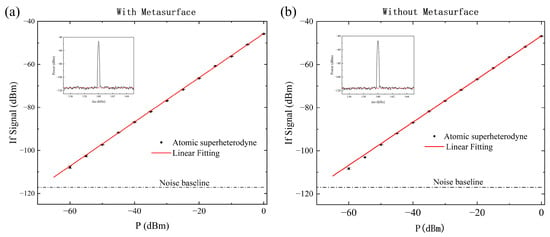
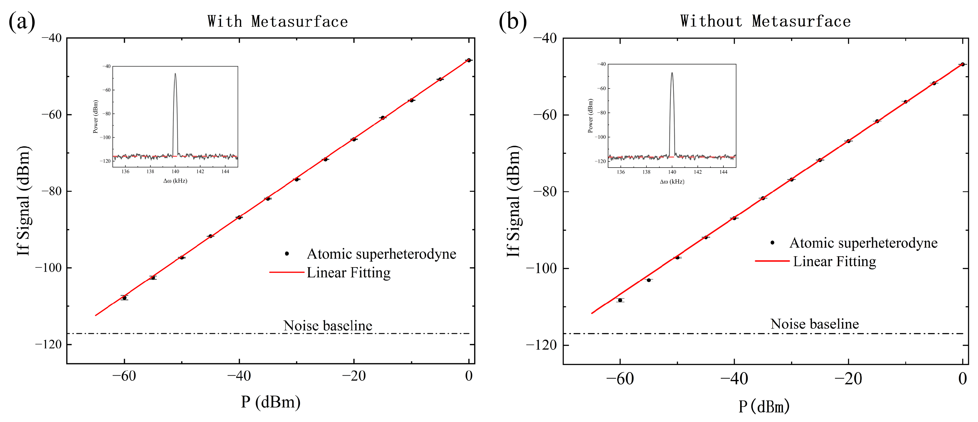
Using the atomic superheterodyne detection scheme, we performed a comparative measurement of the sensor sensitivity for the two configurations, with and without the MS, while keeping the position of the atomic vapor cell and the optical detection conditions unchanged. During the experiment, to minimize the influence of environmental scattering and multipath reflections on the measurement results, absorbing materials were placed around the cesium vapor cell in both experimental configurations. The results indicate that the intrinsic electric-field sensitivity of the atomic system remains essentially unchanged in both cases and is approximately . Moreover, no obvious change in the noise floor was observed, as shown in Figure 4. This indicates that, under the present experimental conditions, the introduction of the MS did not produce any observable effect on the intrinsic noise characteristics of the atomic detector.
Figure 4.
(a,b): Sensitivity of the atomic superheterodyne measurement system with and without the MS, respectively. The black dots represent the average values of 10 measurements, and the error bars indicate the standard deviation. The red solid lines show the linear fits to the data points, while the gray dashed lines mark the noise floor of the atomic system. The insets in the upper left corner of each panel show the Fourier transform spectra of the system response to a beat signal with a frequency offset of between the LO MW field and the SIG MW field.
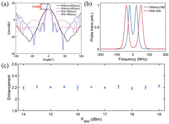
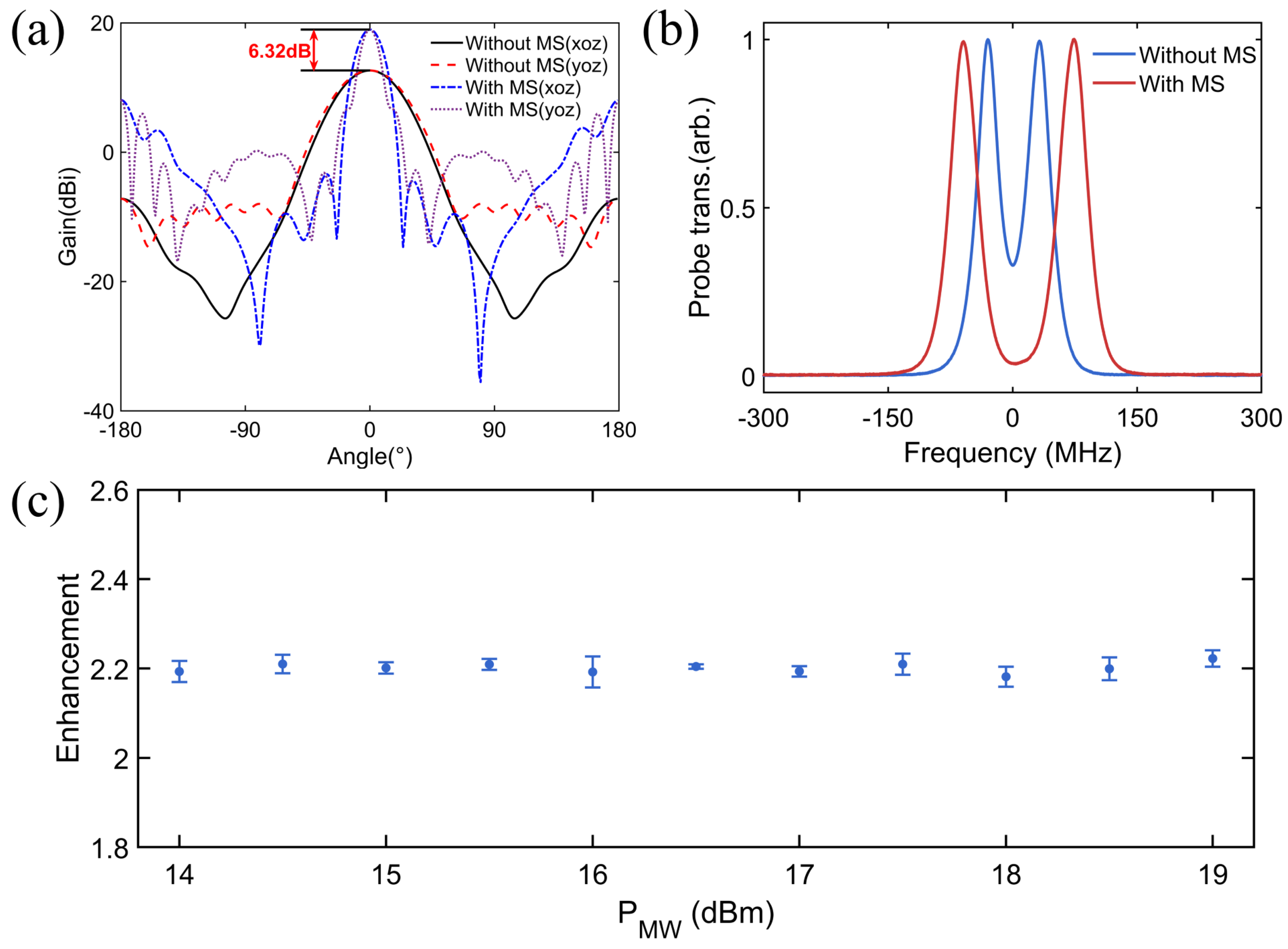
As shown in Figure 5b, under the same MW source power, the introduction of the MS leads to a marked increase in the AT-splitting interval, indicating that the electric field in the atomic sensing region is enhanced. Furthermore, the AT-splitting intervals with and without the MS were measured over a range of MW source powers, as shown in Figure 5c. The results show that the splitting interval in the presence of the MS is approximately twice that measured without the MS. Since the AT-splitting interval is proportional to the electric-field strength, the electric-field-enhancement factor of the MS is approximately .
Figure 5.
(a) Simulated far−field radiation patterns in the and planes with and without the MS. (b) Comparison of the AT splitting with and without the MS under identical MW source power. (c) Electric-field-enhancement factor as a function of the MW source power.
This enhancement factor remains essentially constant throughout the tested power range, indicating that the field-enhancement effect of the MS is independent of the input MW power. This result is consistent with the simulation shown in Figure 5a, where a 6.3 dB increase in power density corresponds to a 2.07-fold enhancement in electric-field strength.
According to the definition in Section 2.3, under the same source power, the introduction of the MS significantly enhances the actual electric-field strength in the atomic detection region compared with the condition without the MS, due to its focusing and enhancement effects on the incident MW. Therefore, while the intrinsic sensitivity of the Rydberg-atom sensor remains unchanged, the hybrid sensor is capable of responding to weaker external incident fields. The equivalent sensitivity of the hybrid sensor can be expressed as
This result demonstrates that the MS improves the equivalent sensitivity of the system for weak external MW electric fields without altering the intrinsic sensitivity of the Rydberg-atom sensor.
It should be emphasized that this improvement in sensitivity does not arise from any change in the Rydberg-atom detection mechanism or the intrinsic noise characteristics of the system. It originates from the wavefront shaping effect of the MS on the incident MW field, which increases the electric-field strength in the atomic sensing region and enhances the equivalent sensitivity of the system.
7. Discussion
During free-space propagation, the microwave field undergoes geometric spreading, which results in a relatively weak electric field within the atomic sensing region. In this work, MS is introduced to perform wavefront shaping of the incident microwave field, thereby redistributing the field in the vicinity of the atom–field interaction region and producing localized field enhancement. This enhancement strengthens the interaction between the microwave electric field and the Rydberg atoms and is ultimately manifested as an improvement in the equivalent sensitivity of the hybrid sensor system.
Compared with other field-enhancement approaches, the present scheme provides a distinct implementation route [34,35,36]. Cavity-enhanced methods, for example, typically rely on the resonant response of a microwave cavity to achieve stronger electric-field enhancement at a specific resonance frequency or within a relatively narrow operating bandwidth, thereby reinforcing the interaction between the Rydberg atoms and the applied microwave field. Under ideal conditions, a high Q microwave cavity can provide strong field enhancement; however, after integration with the cesium vapor cell and the optical detection system, its actual performance is usually affected. In contrast, the MS–Rydberg-atom hybrid sensing scheme proposed here primarily relies on free-space wavefront shaping to realize localized electric-field enhancement within the atomic detection region. Fundamentally, both approaches improve the equivalent detection sensitivity at system-level by increasing the local field amplitude actually experienced by the atoms.
Although the present results verify the feasibility of the MS–Rydberg-atom hybrid sensor, the current implementation still has several limitations. First, the enhancement achieved by the current hybrid sensor is still limited. Second, the metasurface has a limited operating bandwidth, and its performance degrades substantially when the operating frequency deviates from the designed band. Future work may further explore broadband and programmable MS to extend the operational frequency range and improve functional versatility while advancing device miniaturization and integration, thus enabling this hybrid sensing scheme to exhibit greater application potential in more complex practical environments.
8. Conclusions
This work investigates the mechanism of enhancement of sensitivity for weak MW electric-field detection in an MS–Rydberg-atom hybrid sensor. The experimental results show that the introduction of the MS does not alter the intrinsic sensitivity of the Rydberg-atom sensor but provides a stable electric-field-enhancement factor of approximately 2 in the atomic sensing region. This enhancement remains nearly unchanged over the tested range of input MW powers, thereby improving the equivalent sensitivity of the hybrid sensor to external MW electric fields to approximately . These results demonstrate that the MS offers an effective route for improving the detection performance of weak MW electric fields and provides new insight into the design of high-sensitivity, integrated MW electric-field sensors.
Author Contributions
H.Z.: Conceptualization (lead), funding acquisition (supporting), project administration (lead), supervision (lead), and writing—review and editing (equal). Z.C.: Data curation (equal), formal analysis (equal), methodology (supporting), visualization (equal), and writing—original draft (equal). J.H.: Data curation (equal), formal analysis (equal), visualization (equal), and writing—original draft (equal). J.C.: Data curation (equal) and visualization (equal). W.Y.: Methodology (supporting) and writing—review and editing (supporting). M.J.: Supervision (supporting). Z.L.: Funding acquisition (equal), methodology (supporting), and supervision (supporting). J.X.: Funding acquisition (equal), methodology (supporting), and supervision (supporting). L.Z.: Conceptualization (supporting), funding acquisition (equal), project administration (equal), and supervision (equal). L.X.: Funding acquisition (supporting), project administration (supporting), and supervision (supporting). S.J.: Project administration (supporting) and supervision (supporting). All authors have read and agreed to the published version of the manuscript.
Funding
This work was supported by the National Key R&D Program of China (2022YFA1404000, 2021YFA1402004, and 2022YFA1405300), the National Natural Science Foundation of China (12574318, 62201481, 123B2062), the Fund for the Shanxi “1331 Project” Key Subjects Construction and Changjiang Scholars and Innovative Research Team in University of Ministry of Education of China (Grant No. IRT_17R70), and the China Southern Power Grid “Research on Partial Discharge Quantum Detection Technology” (1500002023030103GY00269).
Data Availability Statement
The data that support the findings of this study are not publicly available at the time of publishing this article but can be obtained from the corresponding author upon reasonable request.
Conflicts of Interest
The authors declare no conflicts of interest.
References
- Robinson, A.K.; Prajapati, N.; Senic, D.; Simons, M.T.; Holloway, C.L. Determining the angle-of-arrival of a radio-frequency source with a Rydberg atom-based sensor. Appl. Phys. Lett. 2021, 118, 114001. [Google Scholar] [CrossRef] [Scilit]
- Meyer, D.H.; Cox, K.C.; Fatemi, F.K.; Kunz, P.D. Digital communication with Rydberg atoms and amplitude-modulated microwave fields. Appl. Phys. Lett. 2018, 112, 211108. [Google Scholar] [CrossRef] [Scilit]
- Somaweera, D.; Abdulghani, A.; Odebowale, A.A.; Berhe, A.M.; Weerasinghe, M.I.U.; As’ham, K.; Al Ani, I.A.M.; Dumlao, M.C.; Miroshnichenko, A.E.; Hattori, H.T. Rydberg atom-based sensors: Principles, recent advances, and applications. Photonics 2025, 12, 1228. [Google Scholar] [CrossRef] [Scilit]
- Watterson, W.J.; Prajapati, N.; Castillo-Garza, R.; Berweger, S.; Schlossberger, N.; Artusio-Glimpse, A.; Holloway, C.L.; Simons, M.T. An imaging radar using a Rydberg atom receiver. Appl. Phys. Lett. 2025, 127, 161101. [Google Scholar] [CrossRef] [Scilit]
- Wade, C.G.; Sibalic, N.; de Melo, N.R.; Kondo, J.M.; Adams, C.S.; Weatherill, K.J. Real-time near-field terahertz imaging with atomic optical fluorescence. Nat. Photonics 2017, 11, 40–43. [Google Scholar] [CrossRef] [Scilit]
- Wang, E.-H.; Wang, Q.-F.; Geng, J.-Q.; Tian, T.; Qiu, R.-J.; Xue, B.; Yuan, Y.-W.; Zhao, L.; Ding, D.-S. Investigation of Partial Discharge Detection Based on Rydberg-Atom Electric Field Sensing. Chin. Phys. B 2025. [Google Scholar] [CrossRef] [Scilit]
- Wang, Q.-F.; Zhang, L.-H.; Liu, B.; Ma, Y.; Han, T.-Y.; Wang, E.-H.; Zhang, Z.-Y.; Shao, S.-Y.; Zhang, J.; Li, Q.; et al. Measurement of arc rf signals based on Rydberg atoms. Phys. Rev. Appl. 2025, 24, 014006. [Google Scholar] [CrossRef] [Scilit]
- Wang, E.; Geng, J.; Tian, T.; Qiu, R.; Zhao, L. Integrated Rydberg Atomic Heterodyne Electric Field Sensor for Partial Discharge Signal Detection. In Proceedings of the 2025 International Conference on New Power System Technology (PowerCon), Hefei, China, 24–25 September 2025; pp. 1–5. [Google Scholar] [CrossRef] [Scilit]
- Holloway, C.L.; Gordon, J.A.; Jefferts, S.; Schwarzkopf, A.; Anderson, D.A.; Miller, S.A. Broadband Rydberg Atom-Based Electric-Field Probe for SI-Traceable, Self-Calibrated Measurements. IEEE Trans. Antennas Propag. 2014, 62, 6169–6182. [Google Scholar] [CrossRef] [Scilit]
- Meyer, D.H.; Kunz, P.D.; Cox, K.C. Waveguide-coupled Rydberg spectrum analyzer from 0 to 20 GHz. Phys. Rev. Appl. 2021, 15, 014053. [Google Scholar] [CrossRef] [Scilit]
- Prajapati, N.; Long, D.A.; Artusio-Glimpse, A.B.; Bresler, S.M.; Holloway, C.L. Multichannel, ultra-wideband Rydberg electrometry with an optical frequency comb. Nat. Commun. 2025, 16, 11054. [Google Scholar] [CrossRef] [Scilit]
- Jing, M.; Hu, Y.; Ma, J.; Zhang, H.; Zhang, L.; Xiao, L.; Jia, S. Atomic superheterodyne receiver based on microwave-dressed Rydberg spectroscopy. Nat. Phys. 2020, 16, 911–915. [Google Scholar] [CrossRef] [Scilit]
- Tu, H.-T.; Liao, K.-Y.; Wang, H.-L.; Zhu, Y.-F.; Qiu, S.-Y.; Jiang, H.; Huang, W.; Bian, W.; Yan, H.; Zhu, S.-L. Approaching the standard quantum limit of a Rydberg-atom microwave electrometer. Sci. Adv. 2024, 10, eads0683. [Google Scholar] [CrossRef] [Scilit] [PubMed]
- Zhao, F.; An, Q.; Zhang, J.; Fu, Y. Improving Spectral Resolution of Rydberg Atom-Based Electrometry by 2 × 2 Laser Arrays. Photonics 2025, 12, 1189. [Google Scholar] [CrossRef] [Scilit]
- Rotunno, A.P.; Holloway, C.L.; Prajapati, N.; Berweger, S.; Artusio-Glimpse, A.B.; Brown, R.; Simons, M.T.; Robinson, A.K.; Kayim, B.N.; Viray, M.A.; et al. Investigating electromagnetically induced transparency spectral lineshape distortion due to non-uniform fields in Rydberg-atom electrometry. J. Appl. Phys. 2023, 134, 084401. [Google Scholar] [CrossRef] [Scilit]
- Wang, Q.X.; Liang, Y.K.; Wang, Z.H.; Guan, S.J.; Yang, P.F.; Zhang, P.F.; Li, G.; Zhang, T.C. High-precision measurement of microwave electric field by cavity-enhanced critical behavior in a many-body Rydberg atomic system. Sci. China Phys. Mech. Astron. 2025, 68, 264211. [Google Scholar] [CrossRef] [Scilit]
- Yang, B.; Yan, Y.H.; Li, X.J.; Zhao, H.J.; Xiao, L.; Li, X.L.; Deng, J.L.; Cheng, H.D. Sensitivity of Rydberg Microwave Electrometry Limited by Laser Frequency Noise. Phys. Rev. A 2024, 109, 032609. [Google Scholar] [CrossRef] [Scilit]
- Tang, Y.; Zhou, H.; Yang, C.; Ren, S.; Wang, S.; Lu, C. Noise Performance of a Rydberg Atomic Receiver. Phys. Rev. A 2025, 112, 043106. [Google Scholar] [CrossRef] [Scilit]
- Yan, H.; Jing, M.; Tong, Y.; Yang, W.; Zhang, H.; Liu, Z.; Xie, J.; Zheng, Y.; Xiao, L.; Jia, S.; et al. Sub-shot-noise Rydberg EIT Spectrum. PhotoniX 2025, 6, 54. [Google Scholar] [CrossRef] [Scilit]
- Cai, Y.; Shi, S.; Zhou, Y.; Li, Y.; Yu, J.; Li, W.; Li, L. High-sensitivity Rydberg-atom-based phase-modulation receiver for frequency-division-multiplexing communication. Phys. Rev. Appl. 2023, 19, 044079. [Google Scholar] [CrossRef] [Scilit]
- Meyer, D.H.; Hill, J.C.; Kunz, P.D.; Cox, K.C. Simultaneous multiband demodulation using a Rydberg atomic sensor. Phys. Rev. Appl. 2023, 19, 014025. [Google Scholar] [CrossRef] [Scilit]
- Ding, D.S.; Liu, Z.K.; Shi, B.S.; Guo, G.C.; Molmer, K.; Adams, C.S. Enhanced metrology at the critical point of a many-body Rydberg atomic system. Nat. Phys. 2022, 18, 1447–1452. [Google Scholar] [CrossRef] [Scilit]
- Yu, N.; Genevet, P.; Kats, M.A.; Aieta, F.; Tetienne, J.-P.; Capasso, F.; Gaburro, Z. Light propagation with phase discontinuities: Generalized laws of reflection and refraction. Science 2011, 334, 333–337. [Google Scholar] [CrossRef] [Scilit] [PubMed]
- Engheta, N.; Ziolkowski, R.W. Metamaterials: Physics and Engineering Explorations, 1st ed.; Wiley-IEEE Press: Hoboken, NJ, USA, 2006; pp. 285–369. [Google Scholar]
- Caloz, C.; Itoh, T. Electromagnetic Metamaterials: Transmission Line Theory and Microwave Applications; Wiley-IEEE Press: Hoboken, NJ, USA, 2005; pp. 282–313. [Google Scholar]
- Eleftheriades, G.V.; Balmain, K.G. Negative-Refraction Metamaterials: Fundamental Principles and Applications; Wiley-IEEE Press: Hoboken, NJ, USA, 2005; Chapter 1; pp. 1–41. [Google Scholar]
- Arbabi, A.; Horie, Y.; Bagheri, M.; Faraon, A. Dielectric metasurfaces for complete control of phase and polarization with subwavelength spatial resolution and high transmission. Nat. Nanotechnol. 2015, 10, 937–943. [Google Scholar] [CrossRef] [Scilit]
- Cui, T.J.; Qi, M.Q.; Wan, X.; Zhao, J.; Cheng, Q. Coding metamaterials, digital metamaterials and programmable metamaterials. Light Sci. Appl. 2014, 3, e218. [Google Scholar] [CrossRef] [Scilit]
- Agarwal, G.S. Quantum Optics, 1st ed.; Cambridge University Press: Cambridge, UK, 2012; pp. 145–192. [Google Scholar]
- Chen, M.; Kim, M.; Wong, A.M.H.; Eleftheriades, G.V. Huygens’ metasurfaces from microwaves to optics: A review. Nanophotonics 2018, 7, 1207–1231. [Google Scholar] [CrossRef] [Scilit]
- Yu, N.F.; Capasso, F. Flat optics with designer metasurfaces. Nat. Mater. 2014, 13, 139–150. [Google Scholar] [CrossRef] [Scilit]
- Yang, W.G.; Jing, M.Y.; Zhang, H.; Zhang, L.J.; Xiao, L.T.; Jia, S.T. Radio frequency electric field-enhanced sensing based on the Rydberg atom-based superheterodyne receiver. Opt. Lett. 2024, 49, 2938–2941. [Google Scholar] [CrossRef] [Scilit]
- Wu, F.C.; An, Q.; Sun, Z.S.; Fu, Y. Linear dynamic range of a Rydberg-atom microwave superheterodyne receiver. Phys. Rev. A 2023, 107, 043108. [Google Scholar] [CrossRef] [Scilit]
- Liu, B.; Zhang, L.H.; Wang, Q.F.; Ma, Y.; Han, T.-Y.; Liu, Z.-K.; Zhang, Z.-Y.; Shao, S.-Y.; Zhang, J.; Li, Q.; et al. Cavity-enhanced Rydberg atom microwave receiver. Chin. Phys. Lett. 2025, 42, 053201. [Google Scholar] [CrossRef] [Scilit]
- Liang, Y.; Wang, Q.; Wang, Z.; Guan, S.; Yang, P.; Zhang, Y.; He, J.; Zhang, P.; Li, G.; Zhang, T. Cavity-enhanced Rydberg atomic superheterodyne receiver. Opt. Express 2025, 33, 13034–13039. [Google Scholar] [CrossRef] [Scilit] [PubMed]
- Anderson, D.A.; Paradis, E.G.; Raithel, G. A vapor-cell atomic sensor for radio-frequency field detection using a polarization-selective field enhancement resonator. Appl. Phys. Lett. 2018, 113, 073501. [Google Scholar] [CrossRef] [Scilit]
Disclaimer/Publisher’s Note: The statements, opinions and data contained in all publications are solely those of the individual author(s) and contributor(s) and not of MDPI and/or the editor(s). MDPI and/or the editor(s) disclaim responsibility for any injury to people or property resulting from any ideas, methods, instructions or products referred to in the content. |
© 2026 by the authors. Licensee MDPI, Basel, Switzerland. This article is an open access article distributed under the terms and conditions of the Creative Commons Attribution (CC BY) license.