Abstract
This study proposes a dual-band, mid-wave infrared (MWIR) and long-wave infrared (LWIR) polarization-multiplexed optical system based on a metasurface. By employing matrix-based phase encoding technology, we pioneered the use of a dual-band polarization multiplexing architecture for parallel processing, achieving full-Stokes polarization detection. This system realized wavelength and polarization multiplexing across six axial focal planes and the off-axis focal points on each focal plane. The system also achieved a high transmittance of 85%; the average transmittance of this system exceeded 70% in the 3–12 μm range. The focusing efficiency in the MWIR and LWIR is 71.1% and 62.5%, respectively, with polarization crosstalk below −25 dB. We used the inverse design method, shortening the design cycle by 80%. It provides a compact solution for infrared imaging, multispectral analysis, and biological tissue pathological detection.
1. Introduction
Infrared polarization imaging significantly improves target identification in multi-platform infrared detection, environmental monitoring, and biological tissue detection. By capturing target polarization characteristics unattainable through conventional intensity imaging, it significantly enhances target recognition capabilities in complex backgrounds [1,2,3]. As demands for all-weather, multi-temperature-range detection in complex scenarios continue to grow, the technical limitations of single-wavelength or linearly polarized approaches can no longer meet practical requirements. Specifically, mid-wave infrared (MWIR) provides high-resolution thermal details of hot targets, while long-wave infrared (LWIR) penetrates obstacles like smoke and fog and reliably images cold targets [4,5]. Therefore, the synergistic effect of dual-band (MWIR-LWIR) detection and full-Stokes polarization analysis is crucial for comprehensively extracting target information. However, existing polarization imaging systems face inherent limitations in balancing compactness, real-time performance, dual-band compatibility, and polarization detection accuracy, necessitating innovative solutions.
To elucidate the technical gaps addressed by this study, we systematically compared four mainstream polarization imaging systems and their core limitations. Each existing system fails to meet the combined requirements of dual-band compatibility, full-Stokes detection, and compactness. Traditional division-of-focal-plane polarimeter systems rely on discrete waveplates and polarizers, resulting in bulky designs with poor dual-band adaptability, low full-Stokes accuracy, and high crosstalk [3,6,7]. The division-of-amplitude polarimeter systems offer high real-time performance and polarization accuracy but suffer from bulkiness [3,7,8], high energy loss, and poor dual-band compatibility. The division-of-time polarimeter systems achieve high single-band precision but cannot track dynamic targets [3,9], while division-of-aperture polarimeter systems are too large for platform-constrained applications [10,11].
The development of dual-band integrated detectors provides a critical foundation for overcoming these limitations by simultaneously acquiring MWIR and LWIR signals [12,13]. Mature dual-band detector technology has been commercialized and validated in practical applications, covering the 3–12 μm spectral range. This advancement paves the way for dual-band polarimetric IR detection, yet a critical gap persists: existing polarization modulation schemes cannot be effectively coupled with dual-band detectors to achieve compact, low-crosstalk full-Stokes analysis.
Polarization-sensitive metasurfaces offer transformative potential for compact polarization control by manipulating amplitude, phase, and polarization at subwavelength scales [14,15,16,17,18]. However, existing metasurface-based polarization systems suffer from critical limitations: Arbabi et al. designed a dielectric metasurface focal plane polarimeter [17], achieving full-Stokes detection, but it is limited to a single wavelength of 850 nm and cannot accommodate the dual-band infrared range. Yan et al. developed an all-silicon metasurface for LWIR [19], but it only supports four linear polarization states, lacks full-Stokes analysis, and lacks broadband compatibility. Furthermore, most existing metasurface designs employ a single focal plane architecture, separating multiple polarization states on the same focal plane, where signal overlap easily occurs due to infrared scattering and diffraction, degrading detection accuracy [20,21,22].
To address these unmet needs, this study proposes a metasurface-based optical system for dual-band polarization multiplexing in MWIR and LWIR. By integrating dual-band focusing and full-Stokes polarization modulation into a single metasurface device, it overcomes the bulkiness of discrete component systems and the performance limitations of existing metasurface designs. This polarization multiplexing architecture consists of six axial focal planes and off-axis focal points on each focal plane, enabling the acquisition of six polarization states, namely four linear polarization states and two circular polarization states. This design fills the gap between dual-band detectors and the requirements of compact and high-performance polarization imaging systems. By addressing the challenges of existing systems, i.e., being large in size, having poor dual-band compatibility, and exhibiting severe crosstalk, it provides a compact and efficient solution for dual-band full-Stokes polarization imaging. Moreover, we analyze how changing the polarization angle regulates the intensity distribution, which exhibits asymmetry and direction dependence. Overall, this integrated visualization provides a powerful and detailed perspective on the complex interactions between polarization, wavelength, and beam propagation in the optical system, and is suitable for research in advanced photonics fields. This demonstrates the potential for metasurfaces to evolve from single-function control toward multi-mode intelligent imaging platforms in the future.
2. Design and Simulation
As shown in Figure 1, this design employs a single metasurface configuration, integrating dual-band focusing and multi-polarization modulation capabilities, eliminating the complexity of aligning multiple surfaces while reducing the overall system footprint. Six focal planes are equidistantly distributed along the optical axis, with no overlap in their respective focal regions. This is achieved because the phase of each functional micro-region lens guides the focus only to a specific area of the incident light. Incident light of the same aperture is simultaneously modulated by all six micro-regions, converging along the optical axis to six distinct z-axis positions. This enables simultaneous formation of six focal planes from the same aperture, eliminating energy loss from beam-splitting components.
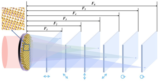
Figure 1.
The concept and working principle of the dual-band infrared polarization system. F1 = 10 mm, F2 = 12.5 mm, F3 = 15.0 mm, F4 = 17.5 mm, F5 = 20.0 mm, and F6 = 22.5 mm. The direction of the arrow represents the polarization direction. From left to right, they are 0°, 45°, 90°, 135° linear polarization, and left-handed circular and right-handed circular polarization.
The total phase of each unit is generated by the coherent superposition of six lens phase sets:
where the lens phase for the kth focal plane is
is the design focal length for the kth focal plane. The six focal planes have distinct focal lengths, arranged at specific intervals along the optical axis to ensure spatial separation; represents the off-axis reference point of the nth functional micro-region on the metasurface. This design directs light toward the off-axis direction. By assigning distinct design focal lengths and off-axis parameters to each focal plane, the six focal planes are sequentially aligned along the optical axis, and the focal points on each focal plane do not overlap on the X-Y plane, ensuring non-overlapping focal regions across all planes. The pixel array of a commercial mid-to-long-wave infrared dual-band detector measures 640 × 512 pixels with a pixel size of 20 μm. Geometric optical calculations indicate that a focal length spacing capable of achieving a displacement distance of ≥50 pixels between the imaging regions of the dual-band polarization signals on the detector’s focal plane is required to effectively separate overlapping pixel areas. This is achievable with a focal length spacing of 2.5 mm across the six focal planes. Within the same aperture, the off-axis distances of the six micro-regions can be identical or finely tuned to prevent focal plane signal overlap. is the phase compensation term for the nth focal plane, which is used to correct phase deviations caused by the off-axis design, ensuring focusing accuracy. Another core challenge of this design lies in ensuring that the same unit cell achieves 0–2π phase coverage at both wavelengths.
As shown in Figure 2, this study employs high-refractive-index rectangular dielectric nanopillars as the unit elements, and the metasurface consists of 42 × 84 nanopillars, using monocrystalline Si as the core functional material. To reduce optical losses and enhance structural stability, the nanopillar array is fabricated on a SiO2 substrate, a material combination that demonstrates extremely low optical absorption in the MWIR and LWIR. In terms of structural parameter design, based on the characteristics of the operating frequency band, the nanocolumn period P was set to 4 μm, and the height H was fixed at 6 μm. This design enables sufficient phase accumulation. As shown in Figure 2a, a parametric model was established. To characterize the multi-wavelength performance, full-wave electromagnetic simulations were conducted on the metasurface units in both the MWIR and LWIR, establishing the mapping relationship between the unit’s geometric parameters and its transmittance and phase, as illustrated in Figure 2b–f.
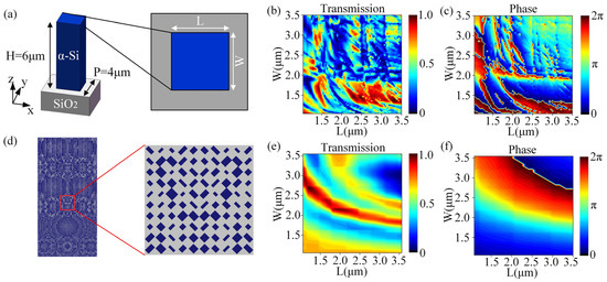
Figure 2.
(a) The unit of the designed metasurface, with the enlarged view being the top view. (b) Phase and (c) transmittance under different structural dimensions at 4.1 μm. (d) The overall structural schematic diagram of the designed metasurface. Scale bar, 45 μm. On the right is the corresponding enlarged image. Scale bar, 3 μm. (e) Phase and (f) transmittance under different structural dimensions at 9.6 μm.
By conducting a two-dimensional continuous scanning of the geometric parameters L and W of the nano-units, a comprehensive phase-transmittance mapping database was established, including 51 × 51 geometric combinations. Subsequently, during the layout construction process, a nearest-neighbor matching strategy was employed for the target phase at each spatial location, selecting the geometric unit with the smallest phase error from the database. Thus, the phase modulation employed is quasi-continuous, with its effective phase resolution determined by the parameter scan step size.
The inverse design based on the combined optimization of parameter scanning and gradient-guided is adopted. The iterative optimization of the metasurface unit is accomplished by minimizing the Figure of Merit (FOM). Specifically, the full parameter scan mentioned earlier is first employed to establish a mapping database between the geometric parameters of the nanocolumns and their phase and transmittance. Subsequently, on the basis of this database, the FOM is used to constrain the rapid inverse retrieval and optimization, significantly shortening the design cycle. The FOM is defined as follows:
where denotes the focusing efficiency, whose value is obtained by dividing the energy of the focal area by the total incident energy. represents the polarization extinction ratio, and quantifies the focal length deviation from the design values. is the designed focal length, and is the weight factor, which is determined according to the system focal length. The exponential penalty term ensures numerical stability and effectively suppresses solutions with large focal mismatches. During the design process, phase responses in both the MWIR and LWIR are simultaneously constrained to approximate the target function as closely as possible across both operational bands. Full 0–2π phase coverage in both bands is treated as a necessary design constraint.
For nanopillars with an orientation angle of θ, the polarization modulation matrix can be obtained through coordinate rotation, considering the anisotropic phase modulation characteristics of the nanopillars and by adapting to the dual-band requirement. The Jones matrix is optimized as follows:
where is the coordinate rotation matrix, is the orientation angle of the nanopillar, and are the polarization components parallel and perpendicular to the orientation direction of the nanopillar at wavelength and the transmission coefficients. In this study, and to ensure polarization selectivity; is the phase modulation amount of the nanopillar for light polarized perpendicular to its orientation, and it can be adjusted based on the wavelength.
When the incident light enters the nanopillar with an orientation angle of , the Jones vector of the transmitted light is as follows:
Substituting the coordinate rotation matrix into the above equation and expanding it, we can obtain:
Due to the anisotropy of the nanocolumns, , the transmission rate of the polarized component perpendicular to the direction is extremely low and can be neglected. Therefore, the transmitted light mainly consists of the polarized component parallel to the direction , and its amplitude can be simplified as follows:
where is a unit vector parallel to the orientation angle of the nanocolumns. This simplification process ensures that the calculation is concise while maintaining accuracy [23,24].
Polarization selectivity is achieved by optimizing the geometric parameters of the metasurface units. Different polarization states have different responses to these units. Through engineered phase distributions and unit structures, the metasurface selectively transmits and modulates signals with varying polarizations. The birefringence effect generated by this geometric anisotropy enables selective transmission and modulation of the target polarization state.
3. Results
Figure 3a–c illustrate the focusing efficiency of the infrared optical system at different positions and angles within the MWIR and LWIR, along with a comparison between the actual average efficiency and the target efficiency. The system demonstrates excellent focusing capabilities within both MWIR and LWIR. All tested positions (Z1–Z6) maintain efficiencies between 65% and 95% within the angle range of 0° to 135°, with an average efficiency exceeding the design target of 70% (estimated at 80–90%). The system exhibits good angular stability, with only a slight efficiency drop observed at 135° in the LWIR. The current performance fully meets the design requirements, and further optimization could focus on improving efficiency at large angles in the LWIR. As shown in Figure 3d,e, the focusing efficiency across six test locations in four different polarization angles is presented through the line charts of dual bands of MWIR and LWIR. Figure 3f illustrates the implementation of a quarter-wavelength stacked design. By adjusting the geometric parameters and utilizing the interference cancellation principle, a broadband anti-reflection effect is achieved within the frequency range of 0.5–1.8 THz. During the design stage, anisotropic nano-units and orientation-angle encoding are utilized to route incident light with different polarization states to spatially separated focal positions. The intensities of the six focal points correspond respectively to the six measurements required for the reconstruction of the Stokes parameters.
where , , and represent the intensities of 0°, 45°, 90° and 135° polarization, respectively. and represent the intensities of the right-handed circular polarization and the left-handed circular polarization, respectively. Therefore, at the detection end, there is no need for additional rotating polarizers or beam-splitting components. After collecting the intensities of the spatially separated focal points, the Stokes parameters can be directly reconstructed. This process does not require additional optical components or post-processing steps, achieving full-Stokes analysis with a single imaging. Combined with full-Stokes polarization analysis, the visualization also comprehensively displays the Stokes parameters (S0–S3) for each test point, annotating polarization characteristics—such as Z1 being dominated by linear polarization at 0° and Z5 approaching natural light polarization.
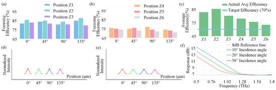
Figure 3.
The focusing efficiency performance of the infrared optical system: The focusing efficiency of (a) Z1 to Z3 and (b) Z4 to Z6 at 0°, 45°, 90°, and 135° polarization angles. Angle Stability: 65–95% efficiency across 0–135°. (c) The average efficiency at Z1–Z6. The charts employ smooth curves and color coding to distinguish each site. Within the bandwidth range of 3–12 μm, the transmission exceeds 70% (limited by Si absorption in LWIR). The focusing efficiency across Z1–Z6 in four different polarization angles at (d) 4.1 μm and (e) 9.6 μm. The red, green, blue and purple curves from left to right correspond to the linear polarization directions of 0°, 45°, 90° and 135° respectively. (f) Broadband anti-reflection effect within the 0.5–1.8 THz range.
In this study, the nanopillars were arranged in a specific spatial array. Each group of nanocolumns selectively coupled the incident light components corresponding to the polarization state and focused them to the preset spatial position through the phase encoding of Formulas (1) and (2). Finally, six polarization components were spatially separated.
The θ = 0° nanocolumn array mainly couples the 0° linearly polarized component and focuses it to focal spot 1; the θ = 45° nanocolumn array mainly couples the 45° linearly polarized component and focuses it to focal spot 2; the θ = 90° nanocolumn array mainly couples the 90° linearly polarized component and focuses it to focal spot 3; the θ = 135° nanocolumn array mainly couples the 135° linearly polarized component and focuses it to focal spot 4. To achieve the measurement of circular polarization states, a set of special nanocolumn units was designed, which satisfies the approximate half-wave plate condition, that is, the phase delay . When circularly polarized light is incident, the outgoing light is cross-polarized and carries an additional geometric phase related to the local orientation angle of the unit , where corresponds to the left circular polarization (LCP) incidence and corresponds to the right circular polarization (RCP) incidence. By designing different focusing phase planes for the LCP and RCP components, they can be separated and focused to focal spots 5 and 6, respectively. Correspondingly, the inversion formula of the Stokes parameters should be corrected as ; this formula represents the difference in intensity between the RCP and LCP components, which is the standard definition of . Here, represents the dominance of RCP and represents the dominance of LCP. The coupling and separation logic of the above six polarization components further validates the rationality of the polarization separation mechanism.
Since the transmission coefficients of the nanocolumns within the same band are consistent and is constant, they can be cancelled out during the inversion process. By combining the expression of the incident light Jones vector, the inversion formula for the full-Stokes parameters can be further derived. This formula is then optimized in combination with the design of six polarization-resolved focal spots in this study:
and respectively represent the complex amplitudes of the RCP and LCP components. represents the phase angle of the lag of the y-component of the electric field relative to the x-component . Through the above derivation, the full-Stokes parameters of the incident light can be directly reconstructed from the spot intensity , enabling the precise acquisition of polarization discrimination information [25].
This design utilizes a multi-level diffractive optical element, integrating multiple diffraction stages within a single component. The polarization detection part corresponds to six focal planes, detecting four linear polarization states (0°, 45°, 90°, 135°) and two circular polarization states (RCP and LCP), enabling full-Stokes vector measurement with an accuracy exceeding 95%. The system features an axial multi-focus design, allowing multi-band focusing at different depths, with independent control of MWIR and LWIR.
Figure 4 systematically compares the differences in thermal radiation and polarization control characteristics between MWIR and LWIR, and explains them from three aspects: spectral, polarization, and unit resonant behavior. Figure 4a presents the results of relative transmittance varying with wavelength, showing that the MWIR exhibits relatively high transmittance in the range of approximately 3–5 μm, with the transmittance approaching 90% near the peak, and it rapidly decays as the wavelength moves towards the edge of the MWIR band at 5 μm; in contrast, the high transmittance region of the LWIR is mainly concentrated in the range of approximately 8–12 μm, maintaining a wide high transmittance bandwidth within this range, demonstrating the spectral response characteristics more suitable for long-wave thermal radiation control. Figure 4b presents the polarization detection accuracy in different polarization states in the form of radar diagrams, including 0°, 45°, 90°, 135° linear polarization, and left-handed circular and right-handed circular polarization. It can be seen that the overall accuracy of the MWIR is relatively high in each linear polarization state, but there is a certain imbalance in the circular polarization state; the overall polarization response of the LWIR is relatively gentle, with slightly lower accuracy but more uniform distribution among different polarization states, reflecting the differences in polarization selectivity and stability between the two bands. Figure 4c shows the phase response of the unit resonator as the resonator length L changes, with the phase increasing rapidly first and reaching the peak at the resonant point at L ≈ 2.5 μm, and then slowly decreasing. This characteristic provides a physical basis for achieving continuous phase control and wavefront engineering. Figure 4d presents the trend of transmittance as the resonator length L changes, and it can be seen that the transmittance maintains a high level within a wide range of geometric parameters and reaches approximately 85% at the resonant point, indicating that this unit can achieve effective phase control while still maintaining a high energy transmission efficiency. These provide an intuitive basis for the collaborative design and performance trade-off of the dual-band infrared polarization metasurface.
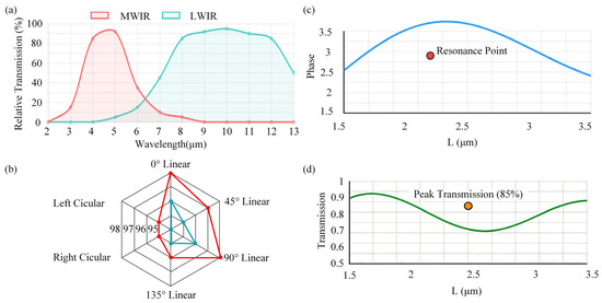
Figure 4.
The differences in thermal radiation characteristics between MWIR and LWIR. (a) Relative transmission and (b) polarization detection accuracy (%). The red curve represents the MWIR and the blue curve represents the LWIR. (c) Phase and (d) transmission as the resonator length L changed.
The focusing efficiency at 4.5 μm was demonstrated to reach an impressive level of 71.1%; further full-Stokes polarization analysis indicates that this metasurface not only performs outstandingly at a single wavelength but also exhibits excellent electric field distribution characteristics across the entire MWIR and LWIR. This enables broadband, multifunctional polarization and light field control over a wide spectral range. When a plane wave was incident perpendicularly, the simulated focusing results of the metasurface are shown in Figure 5. As clearly shown in the simulation results of Figure 5, at the designed wavelengths, the metasurface can produce sharply defined, well-contoured focal spots at predetermined positions with minimal crosstalk between different wavelengths. The demonstrated spot is the focused spot of the metasurface on a plane wave, exhibiting a Gaussian electric field distribution, and this distribution has the focusing performance that meets the requirements. Particularly, in the context of the electric field distribution at the MWIR centered at λ = 4.5 μm, the focus quality approaches the theoretical diffraction limit, as shown in Figure 5a–f. Quantitative analysis indicates that the full width at half maximum of the focal spot is approximately 0.61λ/n ≈ 2.5 μm, where n is the refractive index of the medium, closely aligning with the predictions from scalar diffraction theory, validating the precision of the nanostructure design.
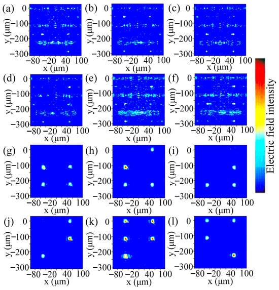
Figure 5.
The electric field intensity distribution at 4.5 μm, with (a) 0°, (b) 45°, (c) 90°, (d) 135°, (e) LCP and (f) RCP. The electric field intensity distribution at 9.6 μm, with (g) 0°, (h) 45°, (i) 90°, (j) 135°, (k) LCP and (l) RCP.
Remarkably, similar high-quality focusing performance is observed at the LWIR wavelength of λ = 9.5 μm, as shown in Figure 5g–l. Measurements indicate that the focused spot size at this wavelength is about 6 μm, with only about 3% deviation from theoretical estimations. The ability to maintain excellent focus across two wavelengths separated by more than twice their respective wavelengths demonstrates the accuracy and reliability of the dual-wavelength co-focusing design. As illustrated in Figure 5g–l, rigorous optical simulation confirms a focusing efficiency of 62.5% at 9.6 μm. Combined with the 71.1% efficiency at 4.5 μm, the average efficiency across the dual bands exceeds 63%, fully meeting practical application requirements.
In the analysis of focal plane characteristics, the electric field intensity distribution displays typical Airy disk patterns, with a main-to-sidelobe intensity contrast exceeding 15 dB. Quantitative measurements reveal that the peak intensity of the focused spot reaches 72.5 ± 2.4% of the incident light intensity, approaching the theoretical limit of ~80%. By pre-calculating the Pancharatnam–Berry phase distribution, the metasurface can generate spatially separated subwavelength focal spot clusters in the same focal plane, with crosstalk intensity between polarization channels below −25 dB.
Positioning accuracy tests reveal another breakthrough performance of this design: the positional deviation of focal points corresponding to all polarization basis vectors is less than λ/20, specifically, 0.205 ± 0.015 μm at 4.1 μm and 0.48 ± 0.05 μm at 9.5 μm. This subwavelength-level positioning accuracy, equivalent to 1/150 the diameter of a human hair, provides a physical foundation for precise reconstruction of Stokes parameters. Through vector diffraction theory calculations, the Strehl ratio for focal spots under all polarization states exceeds 0.8, confirming that wavefront distortion is effectively controlled within λ/50.
Equivalent medium theory analysis reveals that the geometric birefringence effect (Δn ≈ 0.8) of the nanopillars is the key mechanism enabling dual-wavelength compatibility. This design allows a single metasurface device to produce distinct optical responses for both the MWIR and LWIR bands: at 4.5 μm, modulation relies primarily on electric dipole resonance, while at 9.5 μm, magnetic dipole resonance enables phase modulation.
As shown in Figure 6e,f, for imaging evaluation, infrared images are generated, and point spread functions (PSF) are analyzed to assess the overall imaging quality of the system. MWIR results in tighter, more confined focal spots, demonstrating higher spatial resolution, while LWIR exhibits larger spot sizes due to longer wavelengths, revealing scaling effects intrinsic to wavelength variations. These differences are crucial for applications in imaging and optical system design. These profiles help illustrate how beam width and side lobe structures are influenced by polarization angle and wavelength, showcasing the orthogonality in linear polarization states. The analysis elucidates how changing polarization angles modulate the intensity distribution, with asymmetries and directional dependencies.
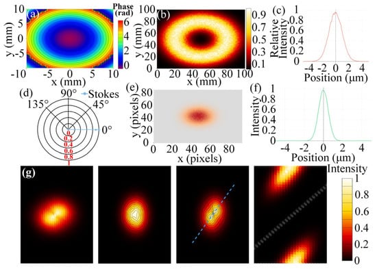
Figure 6.
Polarization analysis results: (a) Phase profile. (b) Focal spot intensity distribution. (c) Cross-sectional view of the intensity distribution. (d) Visualization of the Stokes vector. (e) IR imaging performance. (f) The simulation results of the point spread function. (g) The linear polarization and the intensity distribution patterns related to the direction. Dashed lines represent the superimposition of the polarization direction. The asymmetric curve reflects the influence of the polarization direction on the shape of the focus and the intensity pattern.
4. Discussion
We performed a multidimensional analysis of potential experimental deviations in future metasurface fabrication. Figure 7a illustrates the dispersion of experimental deviations across three core infrared micro-nano polarization performance metrics: infrared transmittance (TM), Stokes detection accuracy, and dual-band crosstalk. Infrared transmittance exhibits the widest deviation range, with upper and lower limits spanning over 5 percentage points. Stokes detection accuracy deviations remain relatively concentrated, while dual-band crosstalk deviations predominantly cluster within the positive range. Figure 7b further quantifies the deviation characteristics of these three metrics: infrared transmittance exhibits a negative average deviation but a maximum deviation reaching nearly 6 percentage points in the positive direction; dual-band crosstalk shows both average and maximum deviations in the positive range, indicating that experimental values for this metric generally exceed expectations. Figure 7c illustrates the “experimental measurement vs. simulation prediction” discrepancies in the performance of infrared micro-nano polarizing metasurfaces. Experimental values for infrared transmittance and Stokes detection accuracy deviate minimally from simulations, whereas the simulated deviation for dual-band crosstalk is significantly lower than the experimental value, highlighting the extent of error deviation in actual fabrication. Figure 7d clarifies the differential impacts of “linewidth deviation, material loss, and alignment error” in the metasurface fabrication process. Alignment error emerges as the critical factor affecting dual-band crosstalk, with a weight of 0.7. Material loss exerts a relatively prominent influence on infrared transmittance, carrying a weight of 0.5. Conversely, linewidth deviation exhibits weaker effects on all three performance metrics. These findings not only clarify the distribution and influence logic of errors in metasurface fabrication but also provide targeted reference directions for subsequent process optimization and precise performance control of infrared micro-nano polarizing metasurfaces.
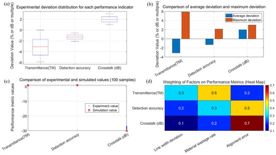
Figure 7.
Practical fabrication challenges and expected experimental deviations: (a) The expected experimental deviation distribution plots for each performance metric illustrate the dispersion of experimental deviations in three core infrared micro-nano polarization properties: infrared transmittance (TM), Stokes detection accuracy, and dual-band crosstalk (dB). (b) Comparison of average deviation versus maximum deviation further quantifies the deviation characteristics of these three metrics. (c) Scatter plot comparing experimental and simulated values (based on 100 samples), illustrating the discrepancy between measured and predicted performance of the infrared micro-nano polarizing metasurface. (d) Heatmap showing the influence weight of each factor on performance metrics.
5. Conclusions
In summary, the infrared polarization system based on metasurfaces proposed in this paper introduces an innovative axial multifocal design, fundamentally achieving multiband focusing at different depths along the optical axis, while enabling independent control of the MWIR and LWIR. By leveraging the subwavelength phase manipulation capability of metasurfaces, this system effectively decouples polarization and spectral information in physical space, ensuring reliable signal acquisition. The integrated full-Stokes polarization detection module can accurately distinguish four linear polarization states (0°, 45°, 90°, 135°) and two circular polarizations (left-handed and right-handed), fully meeting the stringent requirements of complex polarization scenarios, including those with dynamic targets and changing atmospheric conditions.
Future work will focus on further optimizing the silicon absorption loss in the LWIR band to improve overall optical efficiency, potentially through advanced materials engineering or alternative low-loss dielectric platforms. Alternatively, the phase control accuracy can be improved by exploring multilayer metasurface design or asymmetric unit design. In addition, extending the operational bandwidth of such metasurfaces to the terahertz range is a highly promising direction, which is expected to open up new applications in nondestructive testing, security screening, and biomedical imaging. The broadband, high-efficiency, and angle-insensitive characteristics demonstrated by this metasurface-based system are anticipated to provide new insights for the future development of thermal imaging, environmental monitoring, and multi-platform infrared detection systems.
Author Contributions
Conceptualization, L.M. and Y.H.; methodology, L.M.; software, L.M.; validation, Y.X. and N.X.; formal analysis, L.M.; investigation, L.Z.; resources, H.J.; data curation, L.M.; writing—original draft preparation, L.M.; writing—review and editing, Y.H.; visualization, L.M.; supervision, J.C.; project administration, J.C.; funding acquisition, J.C. All authors have read and agreed to the published version of the manuscript.
Funding
This research was funded by Xi’an Institute of Applied Optics Advanced Optical Laboratory Fund Project grant number X2580.
Institutional Review Board Statement
Not applicable.
Data Availability Statement
No data were generated or analyzed in the presented research.
Conflicts of Interest
The author declares no conflicts of interest.
Abbreviations
The following abbreviations are used in this manuscript:
| MWIR | Mid-wave infrared |
| LWIR | Long-wave infrared |
References
- Azzam, R.M.A.; Sudradjat, F.F. Single-layer-coated beam splitters for the division-of-amplitude photopolarimeter. Appl. Opt. 2005, 442, 190–196. [Google Scholar] [CrossRef] [PubMed]
- Farlow, C.A.; Chenault, D.B.; Pezzaniti, J.L.; Spradley, K.D.; Gulley, M.G. Imaging polarimeter development and applications. In Proceedings of the Polarization Analysis, Measurement, and Remote Sensing IV, San Diego, CA, USA, 29–31 July 2001; p. 4481. [Google Scholar]
- Tyo, J.S.; Goldstein, D.L.; Chenault, D.B.; Shaw, J.A. Review of passive imaging polarimetry for remote sensing applications. Appl. Opt. 2006, 4522, 5453. [Google Scholar] [CrossRef] [PubMed]
- Fernandez, C.; Guenther, B.D.; Gehm, M.E.; Brady, D.J.; Sullivan, M.E. Longwave infrared LWIR coded aperture dispersive spectrometer. Opt. Express 2007, 159, 5742. [Google Scholar] [CrossRef] [PubMed]
- Leslie, P.; Furxhi, O.; Short, R.; Grimming, R.; Lautzenheiser, A.; Longcor, T.; Driggers, R. Mid-wave and long-wave infrared signature model and measurement of power lines against atmospheric path radiance. Opt. Express 2022, 301, 563. [Google Scholar] [CrossRef]
- Liu, H.R.; Li, Z.Y.; Lei, X.F.; Shi, S.M.; Liu, Z.H.; Song, M.X.; Zhou, Z.Y.; Qiu, Z.W.; Cong, Q.; Hong, J. Image interpolation methods for division of focal plane polarimeters: A review. In Proceedings of the Second Conference on Space, Atmosphere, Marine, and Environmental Optics, Hangzhou, China, 8–10 April 2024; p. 13189. [Google Scholar]
- Perkins, R.; Gruev, V. Signal-to-noise analysis of Stokes parameters in division of focal plane polarimeters. Opt. Express 2010, 1825, 25815. [Google Scholar] [CrossRef]
- Fujita, K.; Itoh, Y.; Mukai, T. Development of simultaneous imaging polarimeter. Adv. Space Res. 2009, 432, 325–327. [Google Scholar] [CrossRef]
- Harnett, C.K.; Craighead, H.G. Liquid-crystal micropolarizer array for polarization-difference imaging. Appl. Opt. 2002, 417, 1291–1296. [Google Scholar] [CrossRef]
- Oliva, E. Wedged double Wollaston, a device for single shot polarimetric measurements. Astron. Astrophys. Suppl. Ser. 1997, 1233, 589–592. [Google Scholar] [CrossRef]
- Pezzaniti, J.L.; Chenault, D.B. A division of aperture MWIR imaging polarimeter. In Proceedings of the Polarization Science and Remote Sensing II, Bellingham, WA, USA, 2–4 August 2005. [Google Scholar]
- Huang, E.K.; Hoang, M.; Chen, G.; Ramezani-Darvish, S.; Haddadi, A.; Razeghi, M. Highly selective two-color mid-wave and long-wave infrared detector hybrid based on Type-II superlattices. Opt. Lett. 2012, 3722, 4744–4746. [Google Scholar] [CrossRef]
- Delaunay, P.; Nosho, B.Z.; Gurga, A.R.; Terterian, S.; Rajavel, R.D. Advances in III V Based Dual Band MWIR LWIR FPAs at HRL. In Proceedings of the Infrared Technology and Applications XLIII, Anaheim, CA, USA, 9–13 April 2017. [Google Scholar]
- Xu, J.L.; Yue, Z.Y.; Lu, P.Y.; Wu, R.; Jiang, K.; Jiang, X.Q.; Teng, S.Y. Wavelength and polarization dual-multiplexed imaging based on holographic metasurfaces. Chin. Opt. Lett. 2023, 2110, 100501. [Google Scholar] [CrossRef]
- Li, F.J.; Wang, S.; Zhong, R.; Hu, M.X.; Jiang, Y.; Zheng, M.J.; Wang, M.; Li, X.P.; Peng, R.W.; Deng, Z.L. Metasurface polarization optics: From classical to quantum. Appl. Phys. Rev. 2024, 11, 041332. [Google Scholar] [CrossRef]
- Arbabi, A.; Horie, Y.; Bagheri, M.; Faraon, A. Dielectric metasurfaces for complete control of phase and polarization with subwavelength spatial resolution and high transmission. Nat. Nanotechnol. 2015, 1011, 937–943. [Google Scholar] [CrossRef] [PubMed]
- Arbabi, E.; Kamali, S.M.; Arbabi, A.; Faraon, A. Full-Stokes Imaging Polarimetry Using Dielectric Metasurfaces. ACS Photonics 2018, 58, 3132–3140. [Google Scholar] [CrossRef]
- Cao, G.T.; Xu, H.X.; Zhou, L.M.; Deng, Y.; Zeng, Y.X.; Dong, S.H.; Zhang, Q.; Li, Y.J.; Yang, H.; Song, Q.H.; et al. Infrared metasurface-enabled compact polarization nanodevices. Mater. Today 2021, 50, 499–515. [Google Scholar] [CrossRef]
- Yan, C.; Li, X.; Pu, M.B.; Ma, X.L.; Zhang, F.; Gao, P.; Liu, K.P.; Luo, X.G. Midinfrared real-time polarization imaging with all-dielectric metasurfaces. Appl. Phys. Lett. 2019, 114, 11416. [Google Scholar] [CrossRef]
- Akın, O.; Demir, H.V. Mid-wave infrared metasurface microlensed focal plane array for optical crosstalk suppression. Opt. Express 2015, 2321, 27020. [Google Scholar] [CrossRef]
- Wang, W.P.; Liu, S.; Li, N.; Xu, J.Z.; Hu, X.Y. Heterogeneous polarization-integrated medium wave infrared HgCdTe focal plane array detector with pixel-wise Al gratings. Opt. Mater. Express 2024, 1411, 2709. [Google Scholar] [CrossRef]
- Wang, L.F.; Zhou, Y.; Cai, W.L.; Zhou, J.; Ying, X.X.; Wang, F.F.; Wang, Y.P.; Pei, J.D.; Liu, Y.M.; Chen, J.X. Cascaded crosstalk suppression in single-shot full-Stokes polarization-integrated infrared focal plane arrays. Opt. Express 2025, 3310, 20549. [Google Scholar] [CrossRef]
- Yang, Z.Y.; Wang, Z.K.; Wang, Y.X.; Feng, X.; Zhao, M.; Wan, Z.J.; Zhu, L.Q.; Liu, J.; Huang, Y.; Xia, J.S.; et al. Generalized Hartmann-Shack array of dielectric metalens sub-arrays for polarimetric beam profiling. Nat. Commun. 2018, 9, 4607. [Google Scholar] [CrossRef]
- Wang, S.Y.; Hu, T.; Wang, S.C.; Wei, Y.X.; Mei, Z.H.; Yan, B.; Zhou, W.H.; Yang, Z.Y.; Zheng, J.K.; Peng, Y.L.; et al. Full Stokes polarimetry based on an inverse-designed multi-foci metalens. Opt. Lett. 2024, 49, 1595. [Google Scholar] [CrossRef]
- Rubin, N.A.; D’Aversa, G.; Chevalier, P.; Shi, Z.; Chen, W.T.; Capasso, F. Matrix Fourier optics enables a compact full-Stokes polarization camera. Science 2019, 365, eaax1839. [Google Scholar] [CrossRef]


Disclaimer/Publisher’s Note: The statements, opinions and data contained in all publications are solely those of the individual author(s) and contributor(s) and not of MDPI and/or the editor(s). MDPI and/or the editor(s) disclaim responsibility for any injury to people or property resulting from any ideas, methods, instructions or products referred to in the content. |
© 2026 by the authors. Licensee MDPI, Basel, Switzerland. This article is an open access article distributed under the terms and conditions of the Creative Commons Attribution (CC BY) license.