


Abstract
To meet the miniaturization and lightweight requirements of inter-satellite laser communication, this study investigates the servo control system of a silicon-based optical phased array (OPA). Based on the far-field radiation model for beam steering of the silicon-based OPA, combined with thermo-optic phase modulation technology and time domain response, the transfer function of the silicon-based OPA is established. To address noise and disturbances encountered during actual tracking, a silicon-based OPA beam tracking method for satellite platform vibration is proposed. The control algorithm employs a Kalman filter-based Model Predictive Control (KF-MPC) strategy. The advantages of the designed control algorithm were verified through simulations and experiments. Step response simulation results show that compared with the traditional PID control algorithm, the proposed algorithm reduces overshoot by 15.1% and shortens the response time by 76.4%. Sinusoidal tracking simulation results indicate a 27.15% improvement in tracking accuracy over the traditional PID algorithm. Experimental results demonstrate that the tracking accuracy of the servo control system with the proposed algorithm is 155.45 μrad, while that using the PID algorithm is 210.97 μrad, representing a 26.31% improvement in tracking accuracy. This research provides a valuable reference for the application of silicon-based OPA in inter-satellite laser communication.
1. Introduction
The rapid development of Low Earth Orbit satellite constellations has created an urgent demand for high-speed inter-satellite data links. Inter-satellite laser communication, with its advantages of high bandwidth, security and no need for spectrum licensing, is regarded as an ideal solution for building the next-generation space information network [1,2]. The acquisition, pointing, and tracking (APT) system integrated in the laser communication terminal is the core for achieving high-speed laser communication. Its performance directly determines the success rate of establishing inter-satellite laser links and the stability of maintaining them, and fundamentally affects the final communication rate and bit error rate performance. Currently, traditional APT systems still adopt mechanical gimbals and mechanical swing mirrors [3], which have certain advantages in isolating disturbances and resisting shock and vibration. However, they still have problems such as motion inertia, low-speed response, and mechanical wear. As a new type of non-mechanical beam deflection technology, OPA can achieve inertia-free and microsecond-level beam scanning by electrically controlling the phase of light waves. Compared with the traditional mechanical gimbal structures, OPA shows advantages in terms of system volume, weight, speed and reliability, and is suitable for the development needs of lightweight and miniaturized laser communication. It provides an ideal technical path for the new generation of inter-satellite laser communication terminals [4,5]. In recent years, OPA technology itself has shown a diversified development trend. OPA based on various technical solutions such as liquid crystal [6], MEMS [7], and silicon photonics [8,9] has made remarkable progress in performance improvement and application exploration [10,11,12].
At present, there have been reports on the application research of OPA in space optical communication. For instance, Hyun-Woo Rhee et al. [13] utilized a two-dimensional silicon-based OPA to achieve a data transmission rate of up to 32 Gbps, fully demonstrating its potential for realizing high-speed data links. Furthermore, Wenke Jiao et al. [14] proposed a multi-beam OPA based on a silicon nitride platform and demonstrated a 40 Gbps data transmission experiment. However, these demonstrations were mainly conducted under static conditions and did not sufficiently evaluate performance in dynamic tracking scenarios. Lei Chen et al. [15] demonstrated an APT system based on a silicon-based OPA and a four-quadrant detector (QD), and the test indicated that the tracking accuracy (RMSE) of this APT system was 0.024°. However, their research provided limited in-depth analysis of the adopted closed-loop control algorithm. The traditional PID control has been applied and analyzed in liquid crystal OPA systems [16]. However, in complex spatial environments with high dynamics and strong interference, its error feedback control mechanism struggles to maintain system stability and accuracy, making it unable to meet the high standards required for future space applications [17].
To systematically address the aforementioned challenges, this paper proposes a beam tracking method based on silicon-based optical phased arrays (OPAs) under satellite platform vibration. By combining the principle of the silicon-based OPA and the dynamic regulation model of the silicon-based OPA, a transfer function model of the silicon-based OPA is established. In response to noise and interference in the actual application environment, a model predictive control algorithm based on Kalman filtering is designed. An experimental platform is constructed to test the tracking accuracy of the system, and the feasibility of the system is verified.
2. Operational Principle and Performance Characterization of OPA
2.1. Beam Steering Principle of the OPA
The steering capability of an OPA is fundamentally rooted in the principle of multi-beam interference and wavefront shaping. In the horizontal direction, the complex electric field distribution is determined by the phase relationship between the array elements [18].
where is the complex amplitude of the array element, is the number of array elements, is the working wavelength, is the position of the -th element, and is the applied phase. By precisely controlling to satisfy , a high-intensity main lobe is formed at the target horizontal angle .
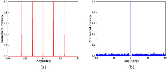
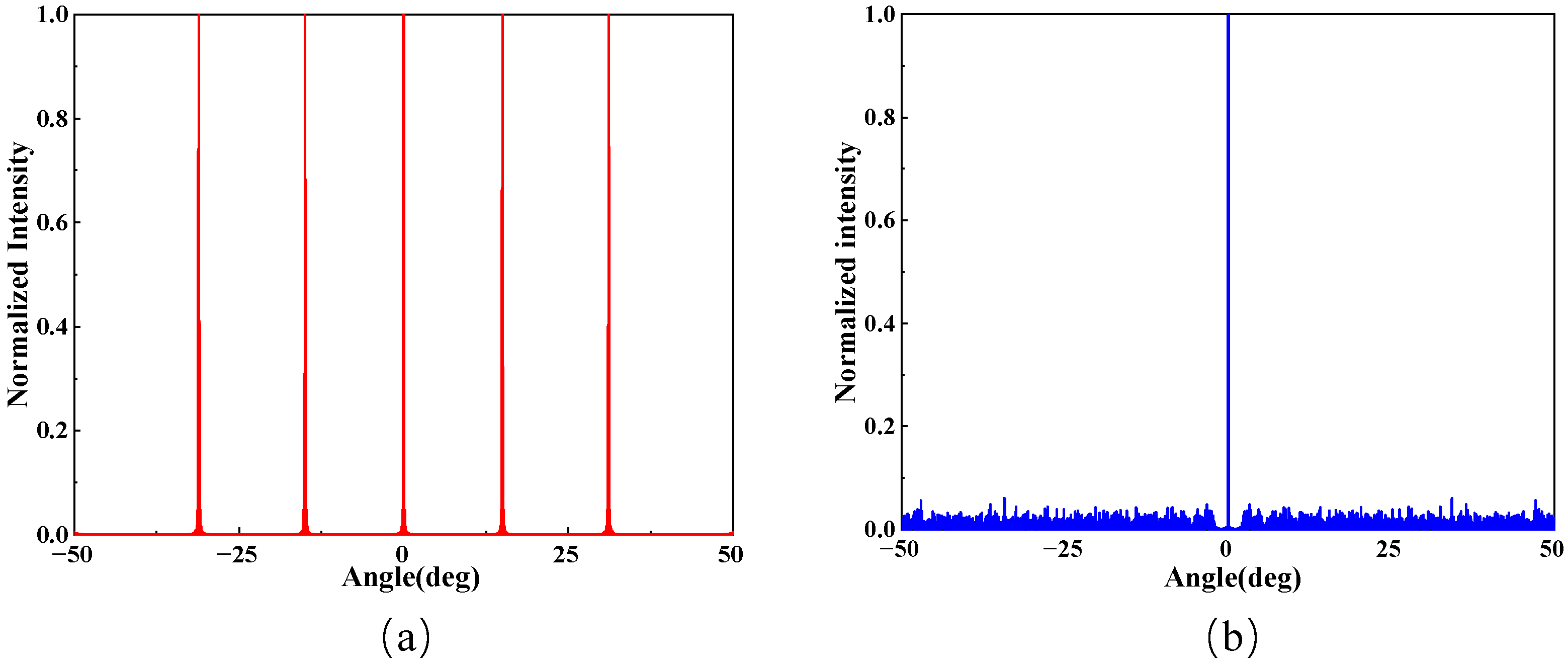
For a uniform OPA with equal element spacing (), periodic grating lobes inevitably appear in the far-field pattern when due to fabrication constraints. As shown in Figure 1a, when the spacing is uniform, the coherent addition of light fields at specific angles creates grating lobes that are comparable to the main lobe. This phenomenon induces spatial aliasing, where the steered beam becomes indistinguishable from its periodic replicas. Consequently, it severely restricts the alias-free Field of View (FOV) and limits the practical steering range of the device. To expand the horizontal scanning range and suppress these unwanted lobes, a non-uniform (unequal) spacing array configuration is typically adopted. As shown in Figure 1b, this approach breaks the spatial periodicity of the array elements, effectively dispersing the grating lobe energy and thereby significantly enhancing the alias-free horizontal scanning range [19].
Figure 1.
Far-field pattern comparison: (a) Uniform array () showing significant spatial aliasing and grating lobes; (b) Non-uniform array where aliasing is eliminated, expanding the effective FOV.
The vertical steering is actively controlled by tuning the operating wavelength of the laser source. For an OPA employing grating emitters, the steering is achieved through the diffraction mechanism of the grating antenna. The vertical exit angle follows the grating equation:
where is the effective refractive index and is the grating period. To quantify the steering sensitivity, the angular dispersion is derived by differentiating Equation (2) with respect to :
where is the group index, which is approximately 4.2 for the 220 nm-thick silicon waveguide in the 1550 nm band. Notably, the steering sensitivity in this dimension is significantly enhanced by the material and waveguide dispersion, as the group index is substantially larger than the modal index .
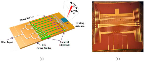
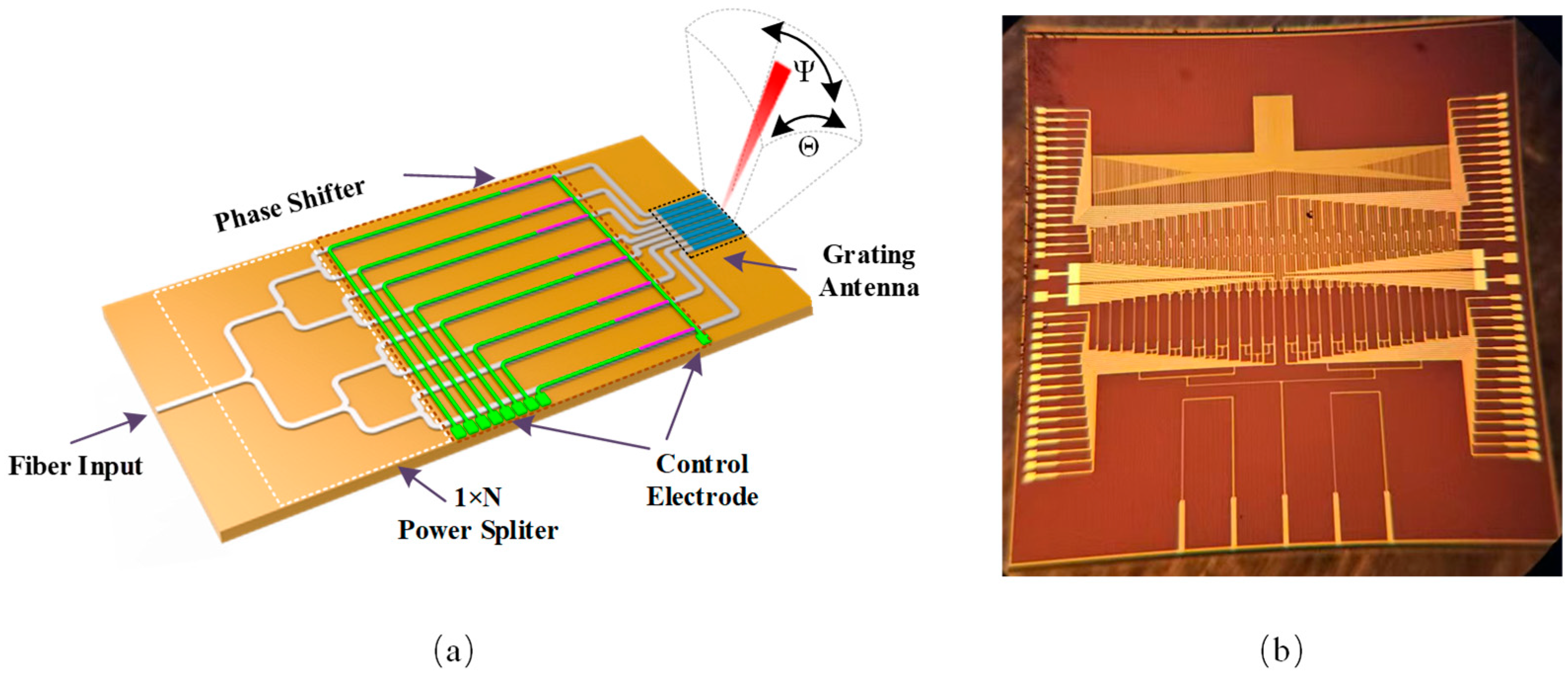
To implement the aforementioned principles, the silicon-based OPA architecture consists of an optical beam splitter network, a thermo-optic phase modulator array, and surface-emitting grating antennas, as shown in Figure 2.
Figure 2.
Silicon-based OPA architecture and implementation (a) Schematic diagram of the silicon-based OPA. (b) Micrograph of the fabricated OPA chip.
To achieve efficient phase regulation, the modulators utilize titanium nitride (TiN) micro-heaters due to their high stability and CMOS compatibility. Furthermore, a shared electrode scheme is employed for the heater array. This design effectively reduces the total number of bond pads and simplifies the routing complexity, thereby significantly saving chip area and reducing overall power consumption. To mitigate thermal crosstalk between dense waveguides, 10 μm-wide air trenches are etched to provide thermal isolation. The specific design parameters of the OPA chip are summarized in Table 1.
Table 1.
Structural parameters of the fabricated silicon-based OPA chip.
2.2. Initial Phase Error Correction
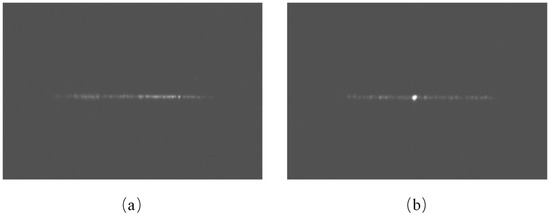
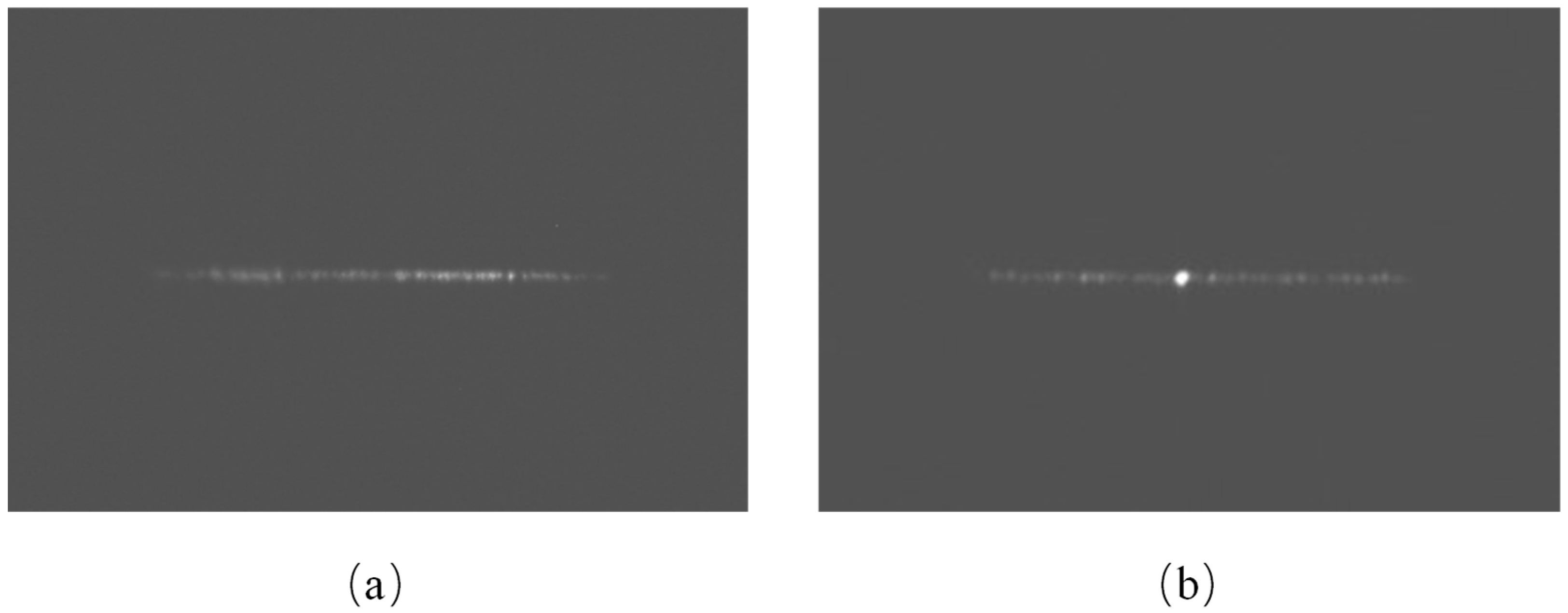
In practical implementation, intrinsic variations between different channels are inevitable due to fabrication non-idealities in the silicon waveguides and phase modulators. These manufacturing-induced discrepancies introduce random initial phase offsets across the array. If the OPA is driven directly without compensation, the destructive interference causes a severe degradation of the main-lobe energy, as shown in Figure 3a. Therefore, to overcome the impact of these channel-to-channel differences, a precise phase error calibration must be performed to restore the beamforming quality before device operation.
Figure 3.
Far-field patterns of the OPA. (a) Before phase calibration (central area masked). (b) After phase calibration.
Typically, a Fourier imaging system consisting of a 4f lens assembly is employed to characterize the far-field properties of the OPA. This configuration effectively maps the far-field radiation pattern from infinity to the focal plane of the lens, enabling the characterization of far-field beam profiles within a compact laboratory setup. By capturing the intensity distribution with the infrared camera, a hybrid Stochastic Parallel Gradient Descent (SPGD) algorithm was utilized for iterative optimization [20]. Using the diffraction efficiency as the objective function, the algorithm iteratively adjusts the phase of each channel to compensate for the manufacturing-induced initial phase errors.
As illustrated in Figure 3b, the far-field beam after calibration exhibits a clearly defined main lobe with significantly suppressed side lobes. By repeating this process across the steering range, a comprehensive phase Look-Up Table (LUT) is established, mapping the precise correspondence between channel phases, operating wavelengths, and spatial steering angles for subsequent high-precision beam pointing by the servo controller.
3. Dynamic Modeling and Servo Control Algorithm
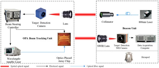
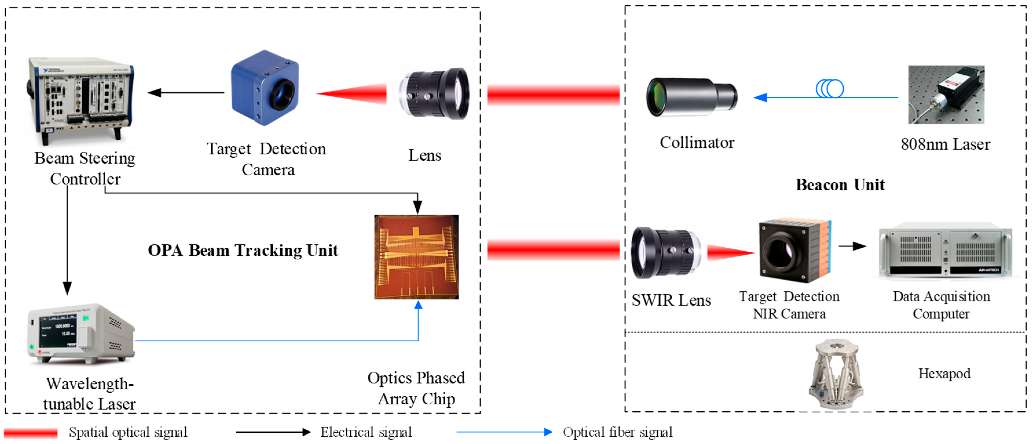
To implement beam tracking, the calibrated silicon-based OPA is integrated into a closed-loop servo control system. The overall operational principle is illustrated in Figure 4. The beacon unit is rigidly mounted on a hexapod platform, which generates motion disturbances based on the satellite vibration spectrum to simulate the inter-satellite link environment. The laser beam emitted from the beacon unit is captured by the target detection camera within the OPA Tracking Unit, which calculates the beam pointing error (spot offset) in real time. This error signal is processed by the beam steering controller, where the control algorithm converts it into driving signals for the OPA chip, achieving precise two-dimensional closed-loop beam pointing. Additionally, a Short-Wave Infrared (SWIR) camera located in the beacon unit receives the steered beam from the OPA to monitor and record the system’s final tracking accuracy.
Figure 4.
Schematic diagram of the silicon-based OPA beam tracking system architecture.
Based on this architecture, this section establishes the dynamic model of the OPA servo systems and details the design of the KF-MPC algorithm based on this model.
3.1. Dynamic Response Characterization
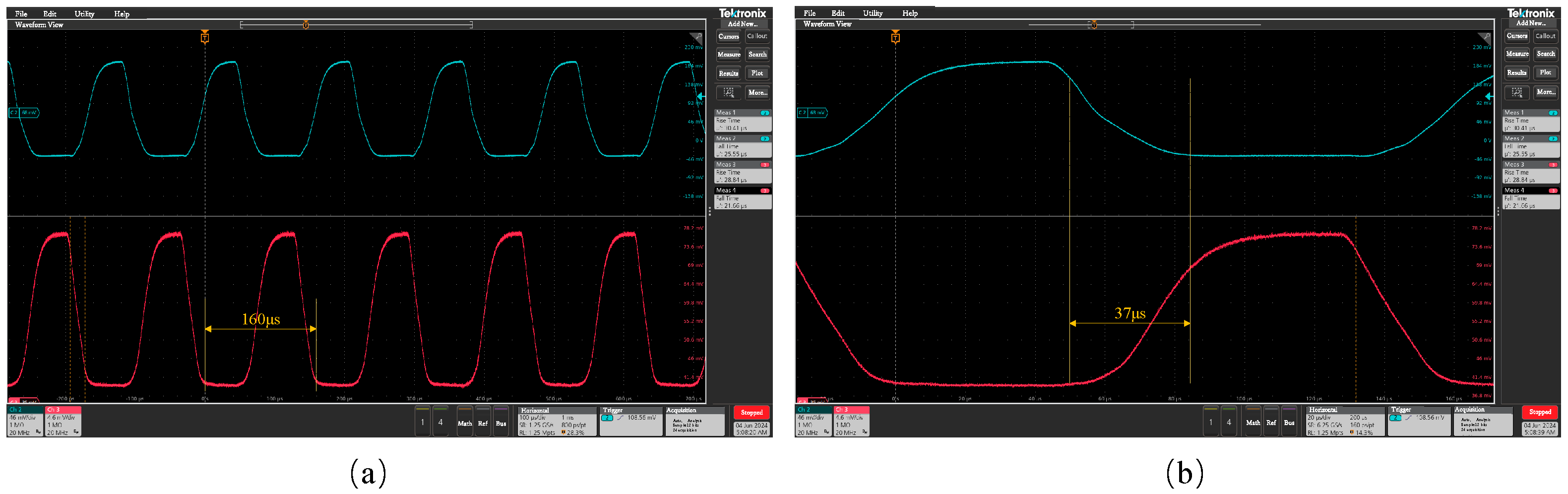
The beam steering speed of the OPA is fundamentally constrained by the thermal inertia of the TiN phase shifters. Since the refractive index modulation relies on the thermo-optic effect, the heat transfer dynamics within the device dictate the maximum scanning bandwidth. To quantify this, we experimentally characterized the temporal response of the beam switching process. The dynamic performance was evaluated by periodically switching the beam between two distinct steering angles. Two photodetectors (DT80, Keshengda Optoelectronics, Chengdu, China) were positioned at the corresponding target angles, separated by 10°, to record the optical intensity variations. Figure 5a illustrates the periodic switching cycles with a repetition period of 160 μs. The results demonstrated that during multiple periodic switching tests, the rising and falling edges of the beam intensity exhibit high consistency and repeatability. This indicates that the device displays no significant hysteresis effect within its operating range.
Figure 5.
Measured dynamic response of the OPA. (a) Periodic beam switching between two angles with a cycle period of 160 μs. (b) Detailed view of the transition.
To precisely analyze the response speed, a detailed view of the transition edge is presented in Figure 5b. The blue trace represents the falling edge of the initial beam, while the red trace shows the rising edge of the target beam. The switching time (), defined as the interval from the 10% decay of the initial beam intensity to the 90% rise of the target beam intensity, was measured to be approximately 37 μs.
Based on this measurement, the phase modulation dynamics can be modeled as a first-order lag system. The transfer function is expressed as:
The relationship between the measured switching time and the time constant is given by . Consequently, the extracted time constant is . Here, the steady-state gain is normalized to , as the static non-linearity between the driving voltage and the phase shift is pre-compensated by the Look-Up Table (LUT) calibration described in Section 2.2. This model serves as the fundamental dynamic constraint for the servo control design.
3.2. Model Predictive Control Based on Kalman Filtering
In practical applications of the silicon-based OPA servo systems, the control environment is frequently affected by process noise, random noise, and external disturbances. Traditional PID control relies solely on error-based feedback and lacks predictive capability, which can result in delayed responses and degraded control performance under strong disturbances. Consequently, its applicability in high-precision silicon-based OPA servo control systems is limited. To achieve high-precision target tracking for the silicon-based OPA servo control system, a KF-MPC control algorithm was designed. Compared with the PID control algorithm, the proposed KF-MPC method combines optimal state estimation with proactive predictive control capability. Kalman filtering can reduce the impact of noise on the system, while the MPC controller can predict future system states and control inputs based on the current state and constraints, and determine the optimal control sequence through receding horizon optimization [21]. The combination of the two improves control accuracy.
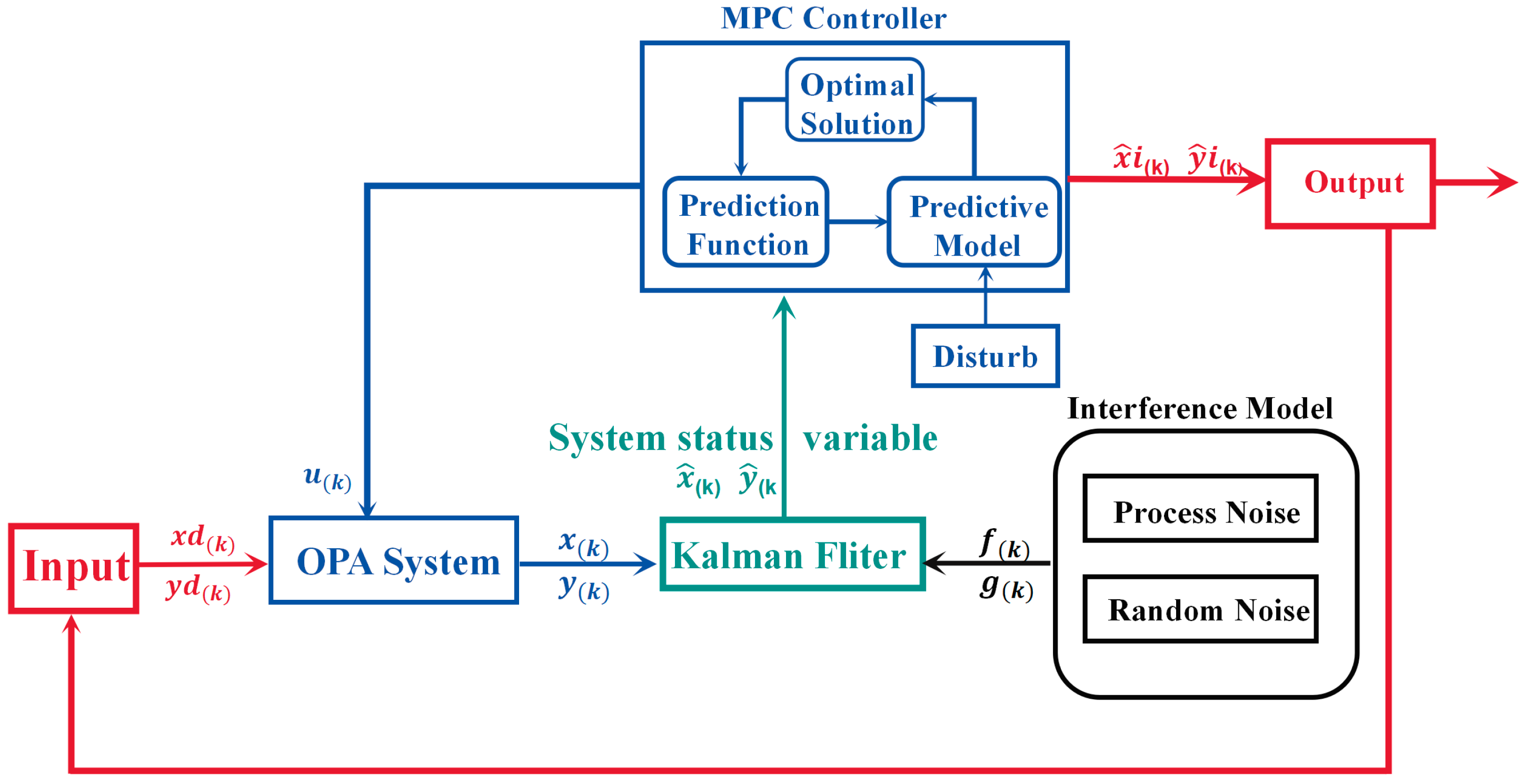
The control block diagram of the silicon-based OPA based on KF-MPC is shown in Figure 6. The overall control block diagram consists of 6 sub-modules: the input module, the output module, the Kalman filtering module, the noise disturbance module, the MPC control module, and the silicon-based OPA model. The input module provides the reference trajectory, while the output module generates the actual system response, and their difference represents the tracking error. Process and random noise are introduced through the interference module and are handled by the Kalman filter and the MPC controller. The Kalman filter and MPC controller are coupled through a closed-loop state estimation optimal control architecture. The Kalman filter estimates the system states using the measured output in the presence of process and random noise, and provides the estimated states as feedback to the MPC controller. Based on these state estimates and the reference trajectory, the MPC predicts future system behavior and computes the optimal control sequence. The resulting control input is applied to the silicon-based OPA servo system, forming a closed-loop process of state estimation, predictive control, and feedback update. The predictive model used in MPC is consistent with that of the Kalman filter, ensuring coordinated operation within a unified dynamic framework.
Figure 6.
Block diagram of the KF-MPC-based OPA control system.
Due to the presence of severe process noise and random noise in practical applications, the silicon-based OPA servo control system was modeled using experimental characterization and theoretical derivation. Based on this process, the transfer function of the system was obtained. The silicon-based OPA servo system is implemented using a digital controller; therefore, its control algorithm is inherently executed in discrete time. To facilitate controller design and system analysis, it is necessary to convert the continuous-time system model into a discrete-time representation.
The state space equation of the continuous state of the silicon-based OPA servo control system can be expressed as:
In the equation, represents the system state vector, denotes the control input, and is the measured output. The terms and account for external disturbances and random noise, respectively.
The optical phased array servo control system is discretized using the zero-order hold (ZOH) method, which assumes that the control input remains constant within each sampling interval. Compared with the Euler method, ZOH more accurately preserves the dynamic characteristics of the continuous-time system and provides better numerical stability. Considering that the silicon-based OPA servo system is of low order with limited bandwidth, the discretization error introduced by the ZOH method is sufficiently small under the selected sampling period. Accordingly, the continuous-time system is discretized via matrix exponential transformation to obtain the discrete-time system matrices.
The state space equation of the discrete state of the silicon-based OPA servo control system can be expressed as:
In the equation, , represent the state vectors of the system at time and time respectively. , , , and are the state space equation matrices of the silicon-based OPA. is the control quantity, is the output of the system at time , is the process noise signal, and is the random noise signal. Both and satisfy the normal distribution, and their probability density functions are:
In the equation, and denote the covariances of the process noise and the random noise , respectively. The Kalman filter first predicts the system state and the corresponding error covariance based on the state estimate at time , the state transition matrix, and the process noise covariance , yielding the predicted covariance matrix . The Kalman filter gain is then computed according to the minimum mean square error criterion. Finally, the state estimate and the covariance matrix are updated using the random information and the observation matrix .
Since the Kalman filter estimates the system state and generates the system state estimate value , which is more in line with the actual state of the system compared to ; therefore, is adopted as the state variable in the system control process. For the control system we have designed, at time , the expression of the state space equation of the system is:
In the equation, is an matrix, is a matrix, and are the state space equation matrices of the silicon-based OPA, and is the process noise.
The core principle of the MPC controller is to minimize a cost function defined within the prediction interval. The prediction interval can be set to , and the input quantities can be expressed as , within the prediction interval.
Define state variable , quantity of state .
Definition the error at time , the error can be expressed as: .
The cost function J can be expressed as Equation (11).
In the equation, and are the weighting matrices for the tracking error and control effort, respectively, while is the terminal weighting matrix used to penalize the prediction error at the end of the prediction horizon. , and are the operation process parameters.
The cost function is optimized through the quadratic programming method, and the solution expression is shown as Equation (12).
When designing the MPC controller, the weight parameters are determined based on the principle that is selected to prioritize tracking accuracy, whereas is chosen to prioritize control input constraints [22]. In this paper A larger is adopted to improve robustness and tracking accuracy under strong disturbances. Through receding horizon optimization, combined with the phased array dynamic control model, the precise control of the silicon-based OPA servo control system is achieved. Since the Kalman filter takes the process noise and random noise into account in the modeling process, it has higher estimation accuracy and noise rejection capability [23]. Adaptive adjustment of the Kalman gain enables the estimated states to closely approximate the actual system states, thereby improving the overall control accuracy of the silicon-based OPA system.
4. Simulated Analysis
To verify the effectiveness of the proposed control algorithm, a simulation model was established in the Simulink environment based on the derived transfer function of the silicon-based OPA, the state-space equations of the OPA control system, and the defined cost function. The controller parameters were set as follows. , , , , , , , and . Comparisons were made in Simulink to verify the differences in the step response and sinusoidal response of the silicon-based OPA under the KF-MPC and PID control algorithms.
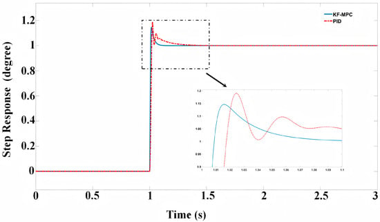
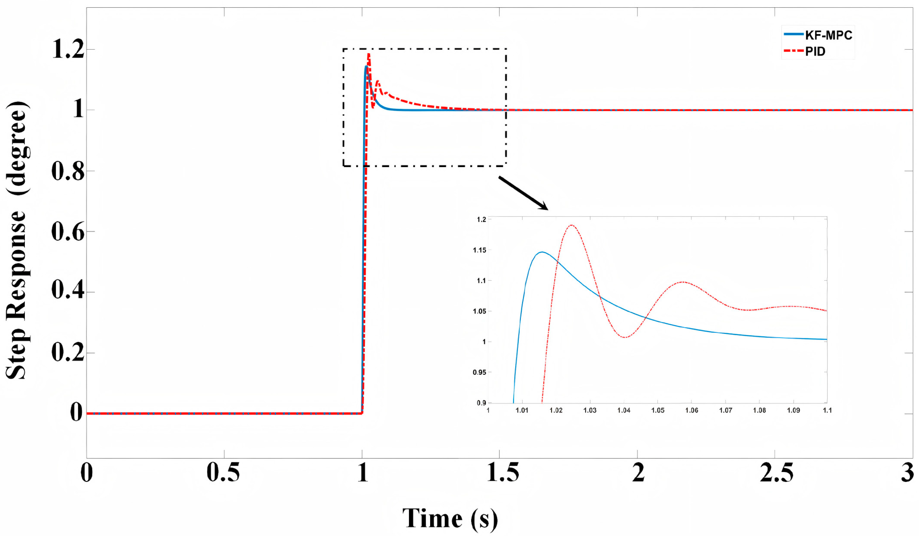
To verify the differences in overshoot and step response time of the silicon-based OPA under the KF-MPC and PID control algorithms during the step response, a step input signal with an amplitude of 1° was given in the input module according to the actual experimental scenario. The step response experiments of the system were conducted, and the comparison analysis graphs of the two algorithms are shown in Figure 7.
Figure 7.
Step response of the silicon-based OPA servo system.
The results showed that the step response of the KF-MPC control algorithm achieved a settling time of 80.4 ms with an overshoot of 16.3%, while the PID algorithm had a settling time of 340.7 ms and an overshoot of 19.2%. According to the simulation experiments, the KF-MPC algorithm reduced the response time by 76.4% and decreased the overshoot by 15.1%, demonstrating significant advantages.
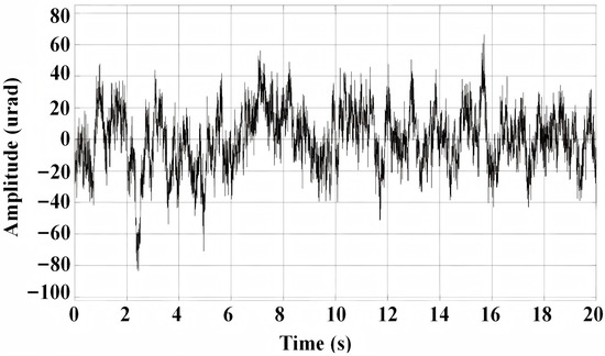
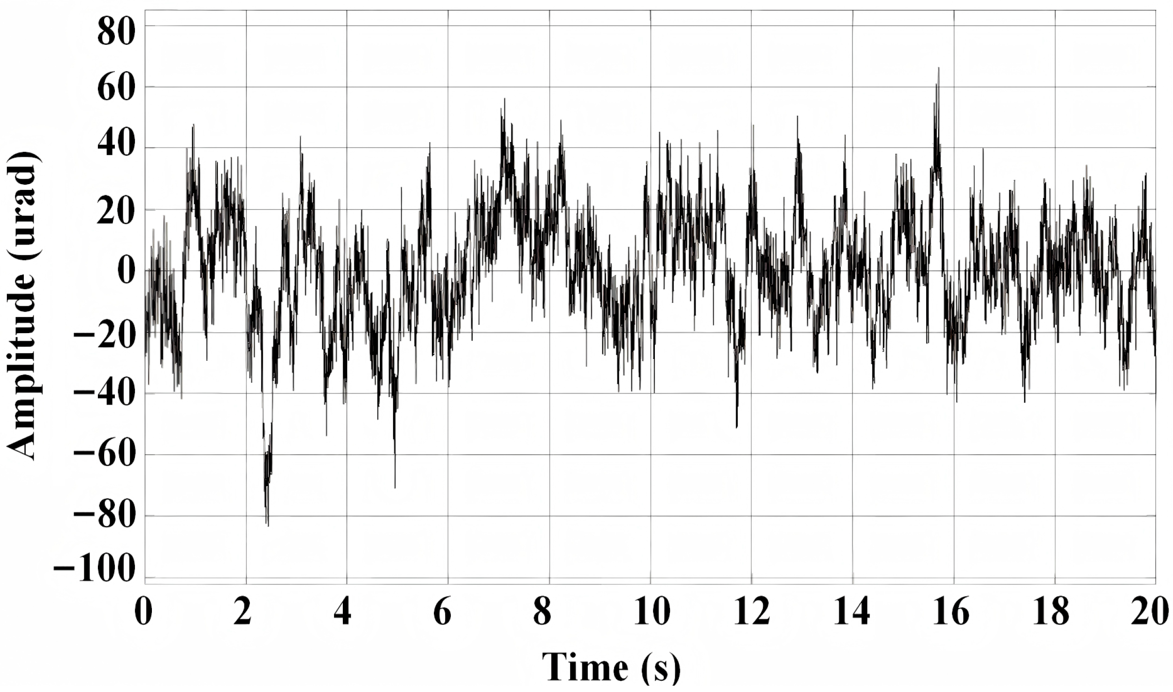
The application scenario of this system is inter-satellite laser communication. While the satellite is in orbit, due to orbital attitude adjustment, satellite maneuvering and periodic changes in the orbit, the pointing angle of the inter-satellite communication link usually shows periodic sinusoidal changes [24]. To more accurately simulate this motion characteristic, taking a typical LEO [25] inter-satellite communication link as an example, the selection of satellite platform vibration uses the SILEX power spectral density of the European Space Agency. The simulation time-domain signal diagram of SILEX power spectral density is shown in Figure 8.
Figure 8.
Time-domain signal of the SILEX power spectral density.
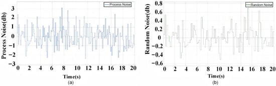
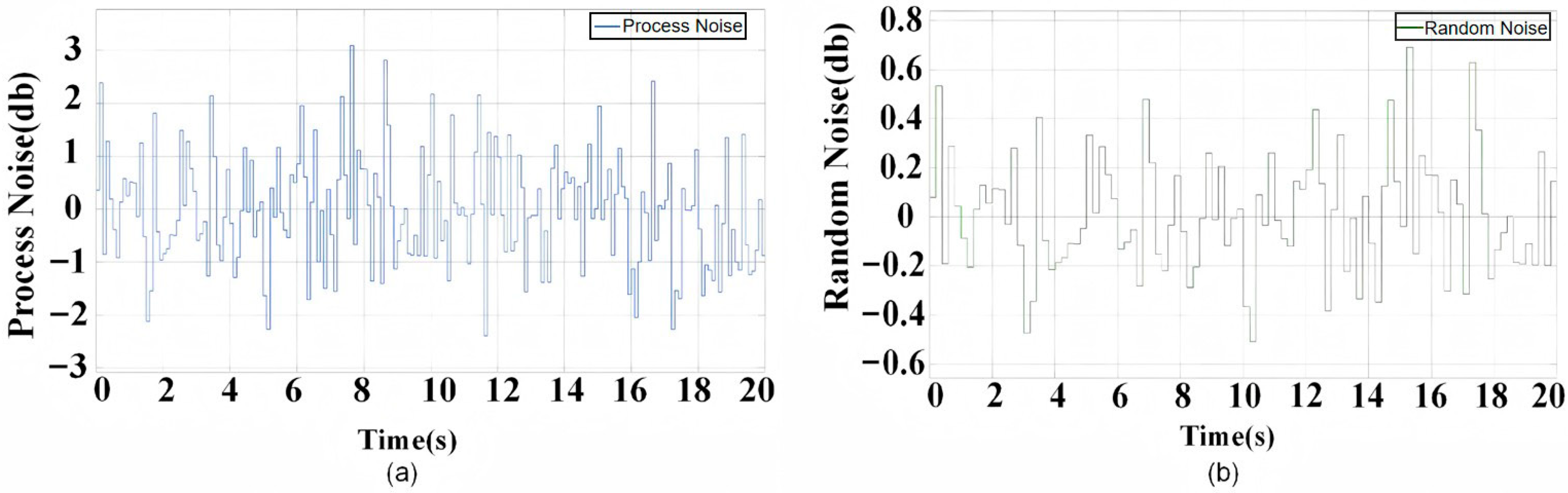
In order to verify the differences in the sinusoidal response of the silicon-based OPA under the two control algorithms (KF-MPC and PID). Based on the relative motion between satellites, a sinusoidal signal with an amplitude of 1° and a frequency of 0.1 Hz was added to the input module. In the disturbance module, a simulation time-domain signal of SILEX power spectral density was added. In the noise module, process and random noise signals were added, both of which were set as Gaussian white noise. The process noise signal graph is shown in Figure 9a, and the random noise signal graph is shown in Figure 9b.
Figure 9.
Time-domain signals of process and random noise. (a) process noise signal diagram of 20 s. (b) random noise signal diagram of 20 s.
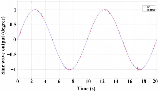
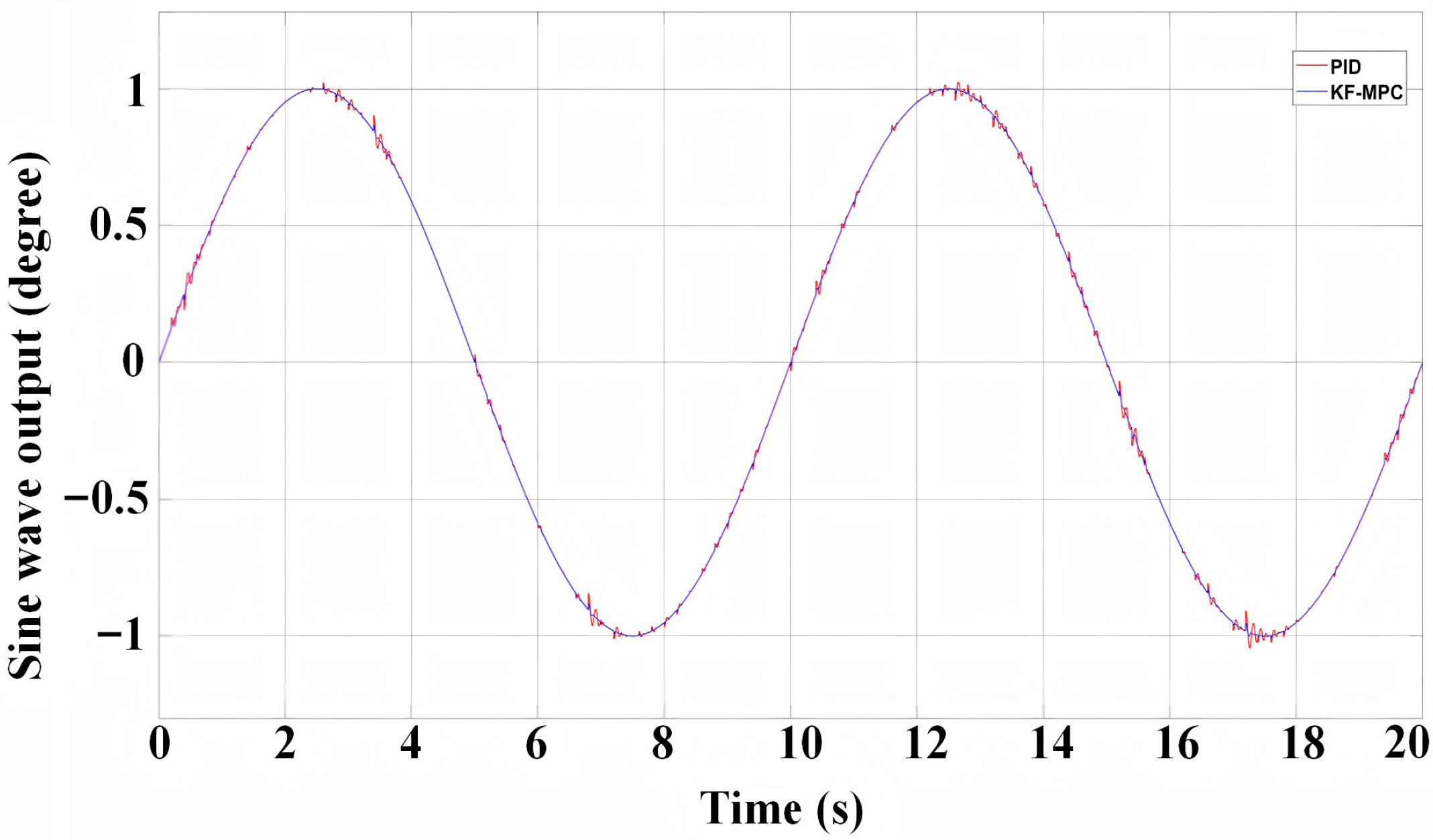
The tracking graph of the sine signal is shown in Figure 10, and the error graph of the stability accuracy of the sine signal is shown in Figure 11.
Figure 10.
Sine wave tracking performance of the silicon-based OPA servo system.
Figure 11.
Sine wave tracking error of the silicon-based OPA servo system.
The results show that the peak value of the tracking error for the sinusoidal response using the PID control algorithm is 738.65 μrad, and the root mean square (RMS) is 176.37 μrad; the peak value of the tracking error for the KF-MPC algorithm is 635.86 μrad, and the RMS is 128.47 μrad. Based on the simulation experiments, it was found that the KF-MPC algorithm improves the tracking accuracy by 27.15%.
5. Experimental Verification
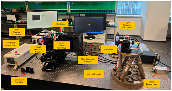
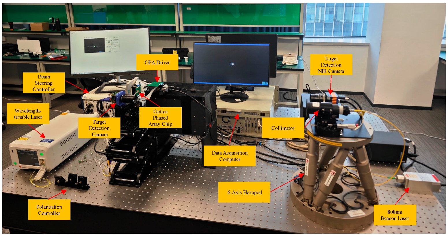
To verify the tracking performance of the silicon-based OPA servo control system using the aforementioned algorithm, an experimental platform was constructed to conduct dynamic tracking experiments. The platform employs a closed-loop control architecture, enabling high-precision beam tracking through real-time adjustment and feedback regulation of the silicon-based OPA. The silicon-based OPA servo tracking system can be divided into two subsystems: the beacon light subsystem and the silicon-based OPA control subsystem. The beacon light subsystem primarily consists of a hexapod (H-850, Physik Instrumente, Karlsruhe, Germany) and an 808 nm laser (MXL-III-808, Changchun New Industries (CNI), Changchun, China) with a collimator, and a short-wave infrared (SWIR) camera (LD-SW6401715, Leading Optoelectronics, Xi’an, China). The silicon-based OPA control subsystem is composed of Upper Computer, OPA Driver, Beam Steering Controller, Wavelength-tunable Laser (TSL-570, Sante, Komaki, Japan), Polarization Controller, Target Detection Camera (GS2020, Henghui Optoelectronics, Changchun, China) and Optical Phased Array Chip. The schematic of the silicon-based OPA servo control system is shown in Figure 12. The experimental procedure follows a sequence from static characterization to dynamic performance, beginning with the characterization of the physical properties of the OPA-steered beam.
Figure 12.
Experimental setup of the OPA beam tracking system.
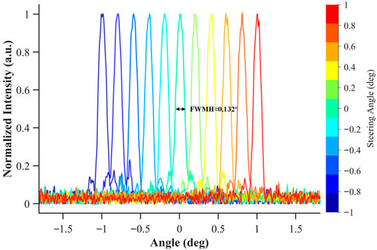
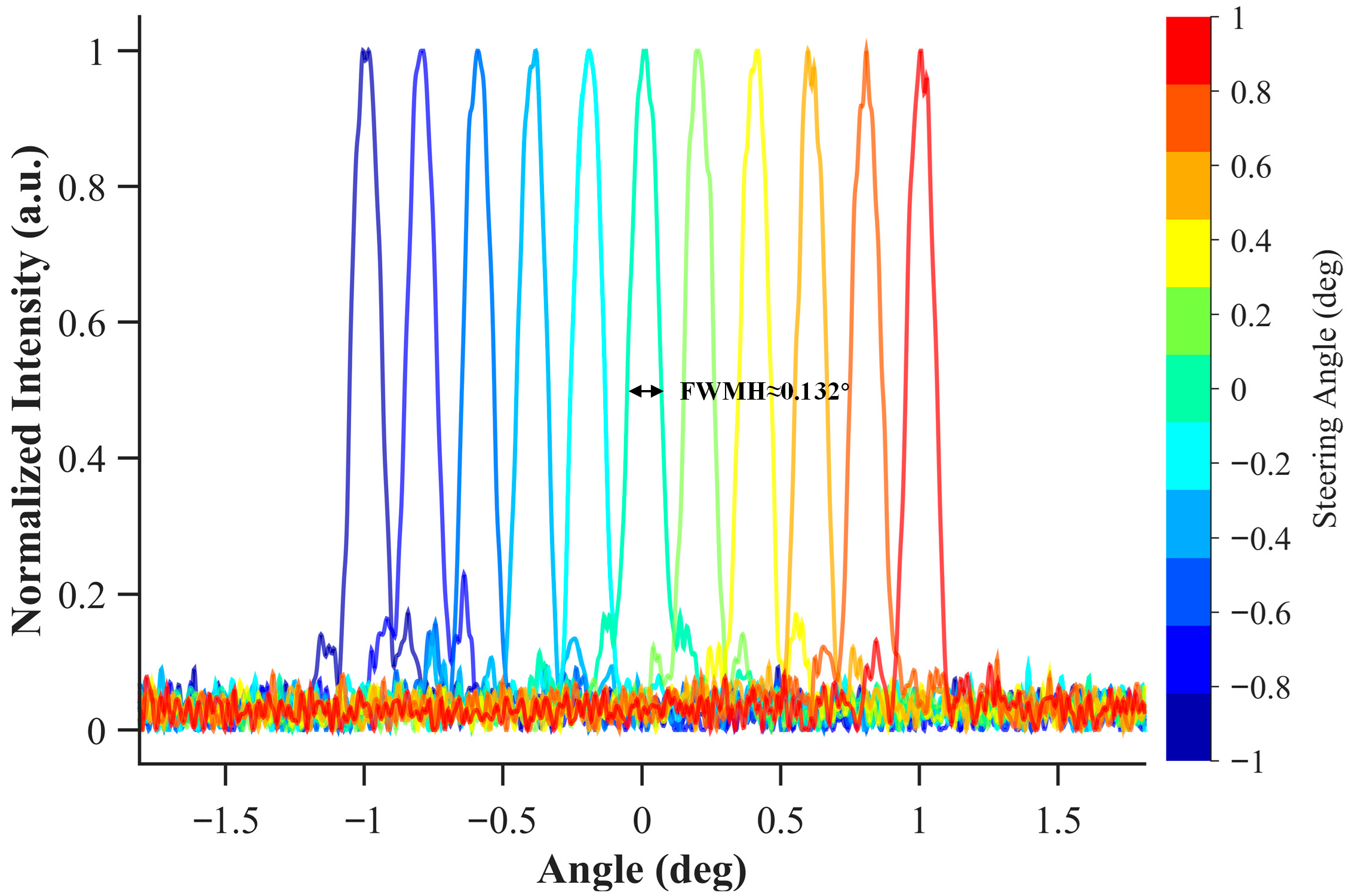
To evaluate the optical performance of the OPA steered beam, its far-field properties were characterized. Figure 13 presents the far-field beam divergence angle within a steering range from −1° to +1°. The beam divergence angle, measured as the Full Width at Half Maximum (FWHM), is 0.0132°. This indicates that the OPA maintains stable beam quality during deflection through phase calibration
Figure 13.
The far-field beam divergence angle of the OPA within a ±1° steering range.
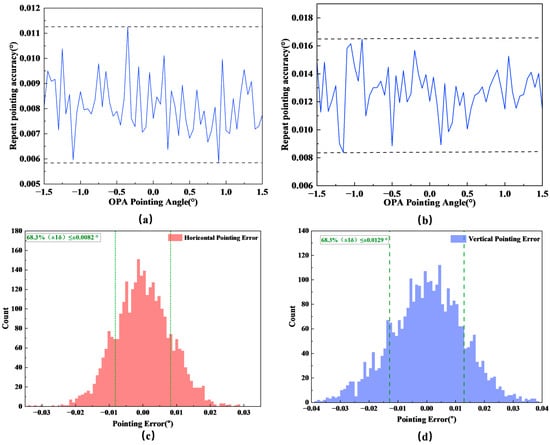
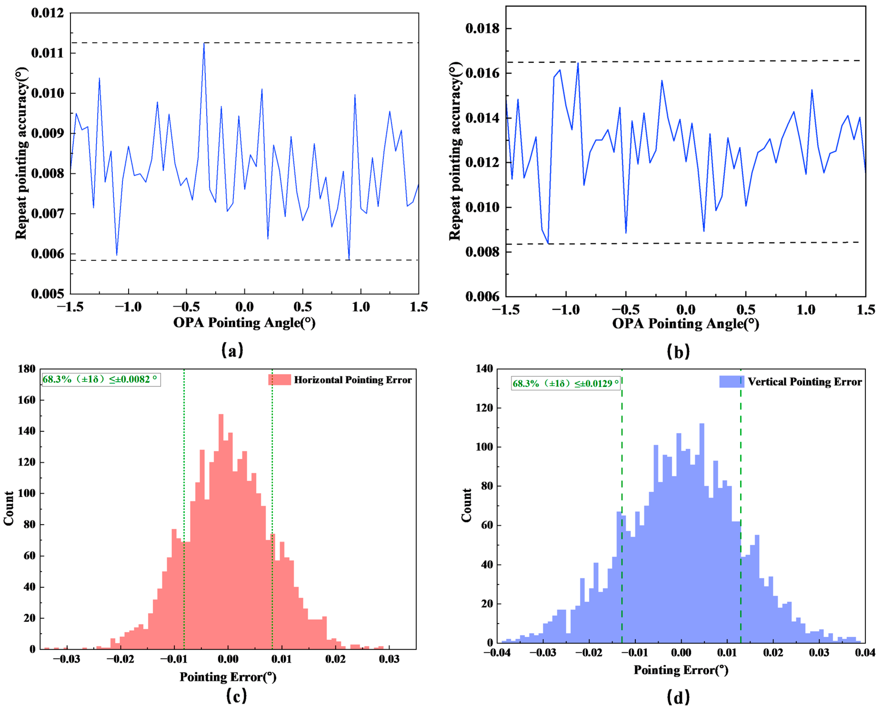
To evaluate pointing accuracy, static pointing error tests were conducted within a ±1.5° range with a step of 0.05°, as shown in Figure 14. Each angle was independently measured 50 times for statistical analysis. The experimental data indicate that the repeat pointing accuracy for the horizontal axis ranges from 0.0058° to 0.0112°, while the vertical axis ranges from 0.0084° to 0.0165°. Analysis of the complete dataset reveals that the pointing errors for both axes follow a Gaussian distribution. The calculated standard deviations (σ) for the horizontal and vertical directions are 0.0082° and 0.0129°, respectively. These statistical results demonstrate good pointing stability and repeatable positioning accuracy.
Figure 14.
Statistical analysis of static pointing accuracy. (a) Horizontal repeat pointing accuracy. (b) Vertical repeat pointing accuracy. (c) Statistical distribution of horizontal pointing errors. (d) Statistical distribution of vertical pointing errors.
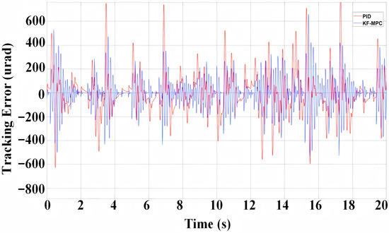
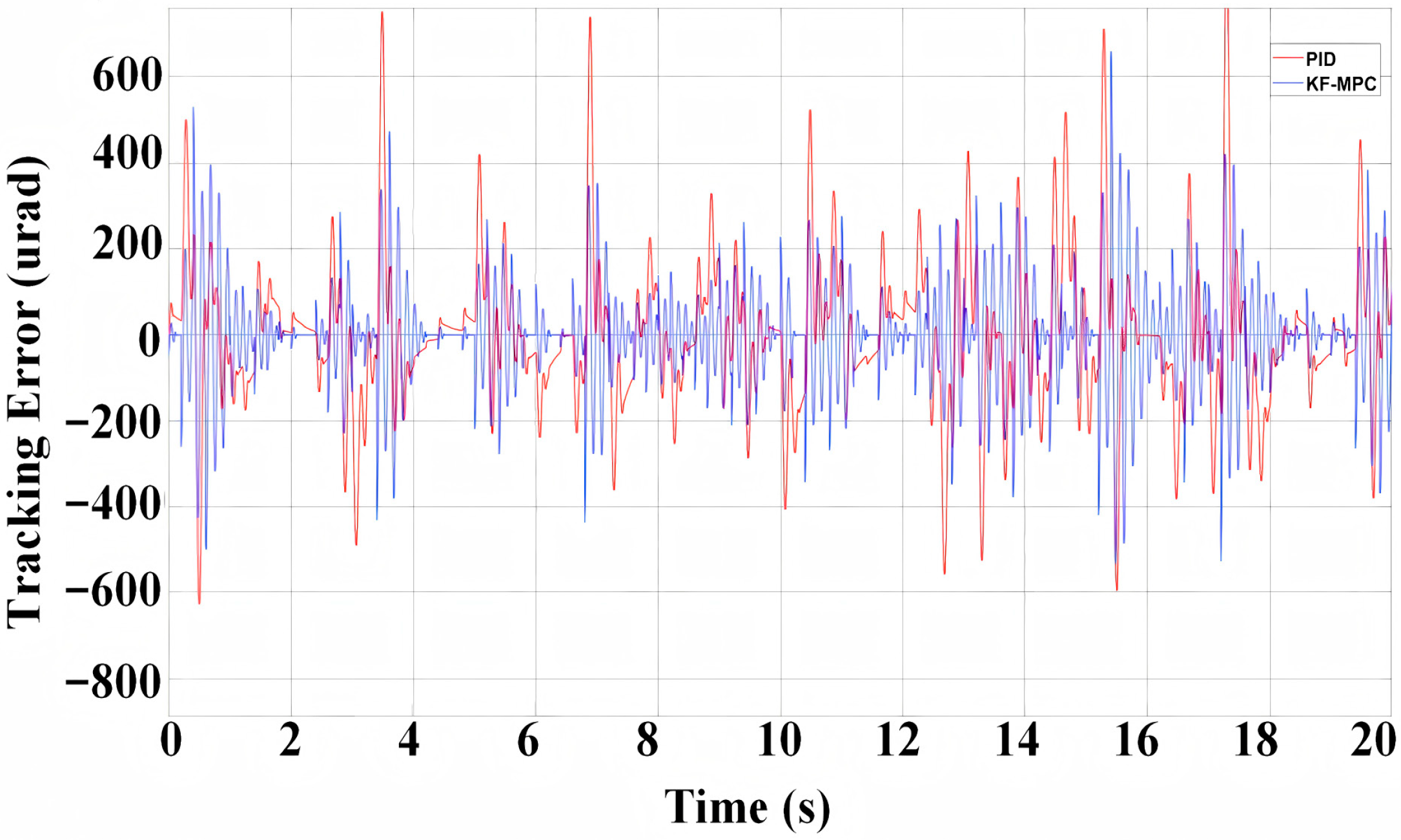
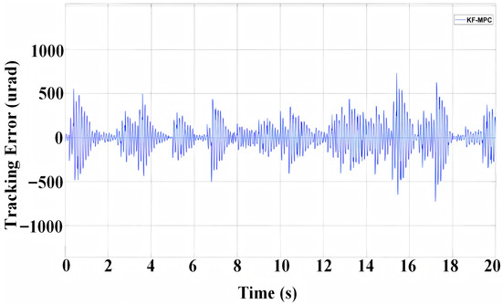
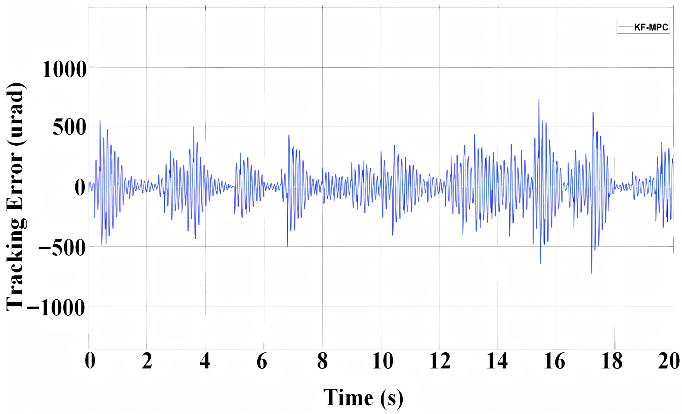
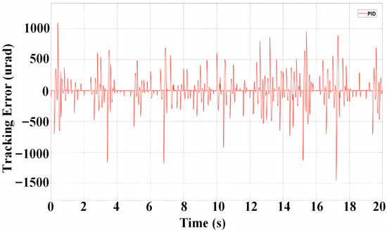
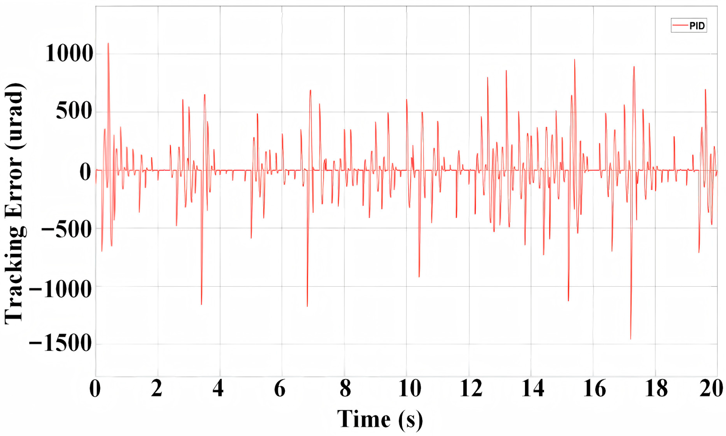
To verify the tracking performance of the silicon-based OPA servo control system after applying the KF-MPC control algorithm, the traditional PID control algorithm was selected for comparison. Tracking experiments were conducted using these two algorithms respectively. The tracking error of the KF-MPC control algorithm is shown in Figure 15, while the tracking error of the PID control algorithm is presented in Figure 16.
Figure 15.
Tracking error of the KF-MPC control algorithm.
Figure 16.
Tracking error of the PID control algorithm.
The upper computer records 1000 off-target quantity data within 0–10 s to statistically calculate the RMS value of the silicon-based OPA servo control system. The experimental results show that the RMS value of the silicon-based OPA servo control system after adopting the KF-MPC is 155.45 μrad, while the RMS value of the silicon-based OPA servo control system using the PID algorithm is 210.97 μrad. Compared with the traditional algorithm, there is a 26.31% improvement.
6. Discussion and Conclusions
In current inter-satellite laser communication systems, traditional mechanical scanning systems are typically employed to achieve spot acquisition, pointing, and tracking. These conventional mechanical scanning systems are constrained by their large size, weight, and power consumption, which significantly limits their response speed and tracking accuracy. Such limitations further increase the difficulty of establishing laser communication links and are prone to causing link establishment failures. As a novel optical component, OPA offers substantial improvements in both size and form factor compared to traditional mechanical scanning systems, making them better suited for inter-satellite laser communication systems.
This paper presents a silicon-based OPA beam tracking approach for satellite platforms subject to vibration, with a Kalman filter-based Model Predictive Control (KF-MPC) algorithm designed. Based on the far-field radiation equation of the silicon-based OPA, a transfer function model of the silicon-based OPA is established, and a KF-MPC controller is developed. Static pointing characterization within a ±1.5° range (0.05° step) shows the OPA’s repeat pointing accuracy of 0.0058° to 0.0112° (horizontal) and 0.0084° to 0.0165° (vertical), with Gaussian-distributed errors (σ = 0.0082° and 0.0129° respectively), verifying its pointing stability. The control performance of the proposed algorithm is verified through simulation and experimental validation. Simulation results show that after applying the KF-MPC algorithm, the overshoot of the silicon-based OPA is reduced by 15.1%, the response time is shortened by 76.4%, and the sinusoidal tracking accuracy is improved by 27.15%. Experimental results indicate that the tracking accuracy of the silicon-based OPA with the KF-MPC algorithm reaches 155.45 μrad, representing a 26.31% improvement over traditional methods. Both simulation and experimental results collectively confirm the effectiveness of the designed control algorithm, facilitating the adoption of silicon-based OPA in miniaturized, lightweight inter-satellite laser communication.
At the current research stage, constrained by experimental conditions, a non-integrated control architecture utilizing an upper computer and external communication interfaces is adopted. To further reduce system Size, Weight, and Power (SWaP) and latency, future implementations can adopt an FPGA-based embedded architecture. By embedding the servo algorithms and LUT directly on-chip, the external Ethernet bottleneck is eliminated, cutting the loop delay from milliseconds to microseconds. This approach will improve closed-loop stability and dynamic tracking performance. In future work, we will focus on integrated system design, aiming to integrate data acquisition and silicon-based OPA control into a single embedded system, thereby drastically reducing system latency and system volume. Additionally, the designed control algorithm currently involves complex computational processes and heavy computational loads. Subsequent efforts will focus on engineering optimizations, such as simplifying non-core parameters.
Author Contributions
Conceptualization, Y.G. and M.Z.; methodology, S.C. and S.T.; software, Y.G. and S.C.; validation, S.T.; formal analysis, M.Z. and S.C.; investigation, Y.G. and S.T.; resources, M.Z. and S.C.; data curation, Y.G. and S.T.; writing—original draft preparation, Y.G.; writing—review and editing, M.Z.; visualization, Y.G.; supervision, S.T.; project administration, Y.G.; funding acquisition, S.T. All authors have read and agreed to the published version of the manuscript.
Funding
This work was supported by the National Natural Science Foundation of China (62231005).
Data Availability Statement
Data underlying the results presented in this paper are not publicly available at this time but may be obtained from the authors upon reasonable request.
Conflicts of Interest
Authors Ye Gu, Shuai Chang were employed by the company Henghui Optoelectronic Measurement Technology (Jilin) Co., Ltd. The remaining authors declare that the research was conducted in the absence of any commercial or financial relationships that could be construed as a potential conflict of interest. The funders had no role in the design of the study; in the collection, analyses, or interpretation of data; in the writing of the manuscript; or in the decision to publish the results.
References
- Wang, G.; Yang, F.; Song, J.; Han, Z. Free space optical communication for inter-satellite link: Architecture, potentials and trends. IEEE Commun. Mag. 2024, 62, 110–116. [Google Scholar] [CrossRef] [Scilit]
- Judice, A.; Livin, J.; Venusamy, K. Research trends, challenges, future prospects of Satellite Communications. In Proceedings of the 2022 2nd International Conference on Advance Computing and Innovative Technologies in Engineering (ICACITE), Greater Noida, India, 28–29 April 2022. [Google Scholar] [CrossRef] [Scilit]
- Yu, D. Research on Optical Communication Technologies and Applications in Satellite Systems. In Proceedings of the 2025 International Conference on Artificial Intelligence, Modern Engineering and Environmental Sustainability (IC-AIMEES 2025), Milan, Italy, 13–14 November 2025. [Google Scholar] [CrossRef] [Scilit]
- He, J.; Dong, T.; Xu, Y. Review of Photonic Integrated Optical Phased Arrays for Space Optical Communication. IEEE Access 2020, 8, 188284–188298. [Google Scholar] [CrossRef] [Scilit]
- Chowdhury, M.Z.; Hossan, M.T.; Islam, A.; Jang, Y.M. A Comparative Survey of Optical Wireless Technologies: Architectures and Applications. IEEE Access 2018, 6, 9819–9840. [Google Scholar] [CrossRef] [Scilit]
- Guo, H.; Li, J.; Wang, X.; Shang, J. Research review on the development of liquid crystal optical phased array device on the application of free space laser communication. In Proceedings of the SPIE 10841, 9th International Symposium on Advanced Optical Manufacturing and Testing Technologies: Meta-Surface-Wave and Planar Optics, Chengdu, China, 30 January 2019. [Google Scholar] [CrossRef] [Scilit]
- Wang, Y.; Zhou, G.; Zhang, X.; Kwon, K.; Blanche, P.-A.; Triesault, N.; Yu, K.-S.; Wu, M.C. 2D broadband beam steering with large-scale MEMS optical phased array. Optica 2019, 6, 557–562. [Google Scholar] [CrossRef] [Scilit]
- Wang, J.; Song, R.; Li, X.; Yue, W.; Cai, Y.; Wang, S.; Yu, M. Beam Steering Technology of Optical Phased Array Based on Silicon Photonic Integrated Chip. Micromachines 2024, 15, 322. [Google Scholar] [CrossRef] [Scilit] [PubMed]
- Yi, Y.; Wu, D.; Kakdarvishi, V.; Yu, B.; Zhuang, Y.; Khalilian, A. Photonic Integrated Circuits for an Optical Phased Array. Photonics 2024, 11, 243. [Google Scholar] [CrossRef] [Scilit]
- Li, Y.; Chen, B.; Na, Q.; Xie, Q.; Tao, M.; Zhang, L.; Zhi, Z.; Li, Y.; Liu, X.; Luo, X.; et al. Wide-steering-angle high-resolution optical phased array. Photonics Res. 2021, 9, 2511–2518. [Google Scholar] [CrossRef] [Scilit]
- Han, R.; Sun, J.; Hou, P.; Ren, W.; Cong, H.; Zhang, L.; Li, C.; Jiang, Y. Multi-dimensional and large-sized optical phased array for space laser communication. Opt. Express 2022, 30, 5026–5037. [Google Scholar] [CrossRef] [Scilit] [PubMed]
- He, X.; Wang, X.; Wu, L. Aperture scalable liquid crystal optically duplicated array of phased array. Opt. Commun. 2019, 451, 174–180. [Google Scholar] [CrossRef] [Scilit]
- Rhee, H.W.; You, J.B.; Han, K.; Kim, M.; Lee, B.G.; Kim, S.-C.; Park, H.H. 32 Gbps Data Transmission With 2D Beam-Steering Using a Silicon Optical Phased Array. IEEE Photonics Technol. Lett. 2020, 32, 803–806. [Google Scholar] [CrossRef] [Scilit]
- Jiao, W.; Chen, J.; Lian, D.; Liu, H.; Zhu, M.; Zhao, S.; Dai, D.; Shi, Y. Two-dimensional multi-beam steering for parallel free-space optical communication based on a silicon nitride optical phase array. APL Photonics 2025, 10, 3678–3681. [Google Scholar] [CrossRef] [Scilit]
- Chen, L.; Zhu, L.; Du, H.; Wang, X.; Shen, S.; Wang, Y.; Zhao, S.; Wang, X. Pointing Acquisition and Tracking System for Free Space Optical Communication Based on Integrated Optical Phased Array. IEEE Photonics J. 2025, 17, 7301608. [Google Scholar] [CrossRef] [Scilit]
- Wang, X.; Xu, J.; Huang, Z.; Wu, L.; Zhang, T.; Wu, S.; Qiu, Q. Theoretical model and experimental verification on the PID tracking method using liquid crystal optical phased array. In Proceedings of the SPIE 10096, Free-Space Laser Communication and Atmospheric Propagation XXIX, San Francisco, CA, USA, 24 February 2017. [Google Scholar] [CrossRef] [Scilit]
- Xia, W.; Mao, Y.; Zhang, L.; Guo, T.; Wang, H.; Bao, Q. Extended State Kalman Filter-Based Model Predictive Control for Electro-Optical Tracking Systems with Disturbances: Design and Experimental Verification. Actuators 2024, 13, 113. [Google Scholar] [CrossRef] [Scilit]
- Zhang, D.; Zhang, F.; Pan, S. Grating-lobe-suppressed optical phased array with optimized element distribution. Opt. Commun. 2018, 419, 47–52. [Google Scholar] [CrossRef] [Scilit]
- Cea, D.M.; Ram, J.R. Critical evaluation of non-uniform optical phased arrays for real-world beam-steering applications. Opt. Express 2024, 32, 26561–26582. [Google Scholar] [CrossRef] [Scilit] [PubMed]
- Zhang, H.; Wang, R.; Du, K.; Zhang, Y.; Jiang, R.; Li, Y. Hybrid algorithm for initial phase calibration of optical phased array. Opt. Express 2024, 32, 5659–5670. [Google Scholar] [CrossRef] [Scilit] [PubMed]
- Cannon, M.; Kouvaritakis, B. Optimizing prediction dynamics for robust MPC. IEEE Trans. Autom. Control 2005, 50, 1892–1897. [Google Scholar] [CrossRef] [Scilit]
- Yao, Y.; Shekhar, D.K. State of the art review on model predictive control (MPC) in Heating Ventilation and Air-conditioning (HVAC) field. Build. Environ. 2021, 200, 107952. [Google Scholar] [CrossRef] [Scilit]
- Zhang, M.; Teng, Y.; Fu, J.; Liu, T. Research on image motion compensation technology in vehicle-mounted photoelectric servo system. Photonics 2025, 12, 154. [Google Scholar] [CrossRef] [Scilit]
- Chen, S.; Yu, X.; Ye, J.; Lin, P.; Zhang, Z.; Wang, T.; Xu, L. High-Precision Position Detection and Communication Fusion Technology Using Beacon Spread-Spectrum Modulation with Four-Quadrant Detector. Appl. Sci. 2024, 14, 3362. [Google Scholar] [CrossRef] [Scilit]
- Zhang, Y.; Ding, R.; Qian, Z.; Liu, M.; Liang, Y.; Jiang, H. Research on High-Speed Clock Synchronization Technology for Inter-satellite Coherent Laser Communication Link. In Proceedings of the 2023 3rd International Conference on Communication Technology and Information Technology (ICCTIT), Xi’an, China, 24–26 November 2023. [Google Scholar] [CrossRef] [Scilit]

Disclaimer/Publisher’s Note: The statements, opinions and data contained in all publications are solely those of the individual author(s) and contributor(s) and not of MDPI and/or the editor(s). MDPI and/or the editor(s) disclaim responsibility for any injury to people or property resulting from any ideas, methods, instructions or products referred to in the content. |
© 2026 by the authors. Licensee MDPI, Basel, Switzerland. This article is an open access article distributed under the terms and conditions of the Creative Commons Attribution (CC BY) license.