


Abstract
We propose an amplitude–phase-asymmetric hyperbolic-chirped double-ring Airy–Gaussian vortex beam (AHC-DRAGVB). Oppositely signed radial chirps are imposed on the inner and outer rings, respectively, while a hyperbolic-cosine amplitude modulation is applied only to the outer ring. A vectorial tight-focusing model based on Richards–Wolf diffraction is used to examine the effects of the scale factor G, vortex displacement, optical distribution factor b, hyperbolic modulation coefficient κ, and radial-chirp coefficients. The scale factor jointly controls the focal position, depth of focus, and longitudinal peak-intensity ratio. Off-axis vortex displacement modifies the focal distribution and reshapes the focal-plane spin density and polarization ellipses. Increasing b changes the relative Gouy phase and the associated local phase slopes and thereby reconstructs the axial spin texture. Increasing κ enhances longitudinal peak weighting, accompanied by changes in focal widths and competing transverse peaks. Radial chirp further shifts the focal region and modifies the local field, although excessive chirp degrades the intensity balance between foci. Rayleigh-force calculations are complemented by three-dimensional force directions and coordinate cuts to examine the local restoring response for b = 0.3.
1. Introduction
The optical manipulation of micro- and nanoparticles offers contact-free operation, low invasiveness, and high spatial precision, and has become an important tool in biomedicine, microfluidics, and precision fabrication. Conventional single-trap optical tweezers generally address one or a few particles locally and are less suited to parallel manipulation or long-range three-dimensional transport. These limitations have motivated the development of structured optical fields [1,2,3,4,5]. Airy beams are representative accelerating fields with quasi-nondiffracting, self-healing, and abruptly autofocusing behavior [6,7,8,9]. Circular Airy–Gaussian beams introduce a Gaussian envelope into a circular Airy field, retaining autofocusing while avoiding the infinite-energy requirement of an ideal Airy solution; they are therefore attractive for optical manipulation.
Coaxial superposition of two circular Airy–Gaussian fields with different ring radii produces a double-ring Airy–Gaussian vortex beam (DRAGVB). Coherent interference between the inner and outer rings can generate optical bottles, multiple foci, and helical propagation patterns, providing additional degrees of freedom for particle manipulation at multiple axial positions [10,11,12,13]. Previous studies have shown that the ring-radius ratio, Airy distribution factor, and topological charge can alter the bottle size, number of foci, and spacing between trapping sites. Recent work also studied dual-ring Airy–Gaussian vortex beams under tight focusing, using ring dimensions and topological-charge matching to tailor optical bottles and multiple spots [14]. The present work adds ring-dependent radial phase and amplitude modulation to this setting, rather than identifying double-ring focusing itself as a new mechanism.
Phase chirp provides an effective means of controlling the focusing evolution of structured light. A radial chirp changes the autofocusing distance of circular Airy-type beams, whereas chirps with opposite signs change the relative radial phase accumulated by the two rings [15,16]. Hyperbolic-cosine modulation can simultaneously reshape the outer-ring amplitude and alter the amplitude matching between the two rings. We therefore introduce an amplitude–phase-asymmetric hyperbolic-chirped double-ring Airy–Gaussian vortex beam (AHC-DRAGVB). Opposite quadratic radial phases are applied to the inner and outer rings, and only the outer ring is modulated by a hyperbolic-cosine amplitude factor. The resulting field combines distinct pupil phase and amplitude controls over the coherent superposition and autofocusing evolution of the two rings.
Distinct from existing demonstrations of autofocusing, vortex manipulation and tightly focused optical bottles [10,11,14], our modulation strategy uses opposite quadratic phases on two rings and a hyperbolic envelope only on the outer ring for coherent phase–amplitude tailoring, requiring no variation in ring radii or vortex orders. Specifically, the relative chirp phase is (Cin − Cout)r2, while only the outer-to-inner amplitude ratio acquires cosh(κqout). Relative phase and amplitude can therefore be varied without changing the ring radii or vortex orders. This adds a route to tailor focal position, longitudinal weighting and local polarization.
Recent vortex studies link vortex-pair control to photonic spin Hall symmetry [17], relate longitudinal spin splitting to the Goos–Hänchen shift [18], demonstrate reflection-induced C-point polarization-structure transitions [19], and show reconfigurable free-space optical skyrmion topology [20]. These studies motivate examining relative focal-component phase and spin orientation; the present spin trajectories do not by themselves establish a spin Hall displacement or skyrmion invariant.
Using the Richards–Wolf vector diffraction theory, we establish a tight-focusing model of the AHC-DRAGVB and investigate how the scale factor G, vortex-pair displacement, optical distribution factor b, hyperbolic modulation coefficient κ, and inner- and outer-ring chirp coefficients affect the focal electric field, spin density, polarization state, and optical force on Rayleigh particles [3,21,22,23,24,25,26,27,28]. The x–z intensity distribution, focal-plane vector field, focal locations, axial interaction range, threshold-defined transverse dimensions, interference sidelobes, and longitudinal peak-intensity ratio are analyzed to clarify the available parameter-control mechanisms.
2. Theoretical Model and Computational Methods
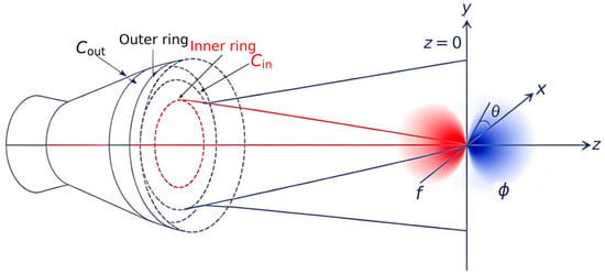
Figure 1 illustrates the tight-focusing geometry of the AHC-DRAGVB. The incident field consists of two concentric Airy–Gaussian annular fields with different orbit radii. The origin of the Cartesian coordinate system is placed at the geometrical focus. The lens is assumed to be aplanatic and to satisfy the sine condition, so that the radial pupil coordinate is r = f sin θ, where f is the focal length and θ is the polar angle. The inner- and outer-ring fields in the input plane are denoted by Ein(r, φ) and Eout(r, φ), respectively, and are written as follows [21].
Figure 1.
Schematic of the tightly focused asymmetric double-ring Airy–Gaussian vortex beam. The inner and outer rings have different radii and radial chirp coefficients Cin and Cout; f is the focal length, and θ and φ denote the polar and azimuthal angles, respectively.
Here, qj = (G rj − r)/(G b w0), j = in or out. The factor exp(aGqj) follows the supplied numerical definition. Ai is the Airy function; G is the scale factor; a is the truncation factor; b is the optical distribution factor; w0 is the transverse length scale; and rin and rout are reference ring radii. The shared displaced vortex product is
The vortex orders are m = n = 1; their positions are x = rk1 and x = −rk2. The dimensionless hyperbolic coefficient is κ; Cin and Cout have units m−2. The total incident field is
According to the Richards–Wolf vector diffraction integral, the electric field of an x-linearly polarized AHC-DRAGVB at the observation point is
The polarization vector is p = (cosθ cos2φ + sin2φ, (cosθ − 1)cosφ sinφ, −sinθ cosφ)ᵀ. We use exp(−iωt); the chirp signs specify opposite quadratic pupil phases.
Here, k0 = 2πnm/λ, λ = 532 nm, and α = arcsin(NA/nm). The medium index is nm, whereas n denotes the second vortex order. The angular frequency is ω = 2πc0/λ. The incident field is linearly polarized along x. Numerical integration yields Ex, Ey and Ez. After removing the common propagation phase, their component and relative phases are
The vectors α(r), β(r) and γ(r) describe the major axis, minor axis and normal of the three-dimensional electric polarization ellipse [22,23,24,25,26]. The following expressions apply away from the circular-polarization degeneracy E·E = 0; at a degeneracy, the ellipse axes require a limiting construction.
The polarization ellipse lies in the plane spanned by α and β. For peak-amplitude phasors in air, its normal is parallel to the electric contribution to the time-averaged spin density [22,23,24,25],
Here, ε0 is the vacuum permittivity and ω is the angular frequency. We use a unit vector to describe spin orientation, rather than an energy-normalized spin magnitude:
The unit vector is undefined at zero spin. The auxiliary quantities are
Under the Rayleigh approximation, a nonabsorbing particle with rp = 20 nm < λ/20 is treated as an electric dipole. We use np = 1.59, nm = 1 and nr = np/nm, with c0 = 299,792,458 m s−1 and ε0 = 8.85,418,781,28 × 10−12 F m−1. The static polarizability and radiation-reaction correction are [28,29,30]
The momentum term generalizes the scattering contribution to local phase gradients in all three directions. It is not constrained to point along z. Spatial derivatives are evaluated analytically inside the diffraction integral at the requested coordinates. The complete time-averaged force is
All simulations use NA = 0.95, nm = 1, λ = 532 nm, w0 = 3 mm, a = 0.1, m = n = 1 and x-linearly polarized input. The second vortex order is called l in the source programs. The transverse scale w0 uses italic Latin w, not the angular frequency ω. The pupil radius is R = f sinα = 0.95f; r0max in the displacement notation denotes R. Original x–z field calculations sample −4 ≤ x/λ ≤ 4 and −50 ≤ z/λ ≤ 50 on a 200 × 200 grid; the polar-angle integral uses 200 samples over 0 ≤ θ ≤ α. Figure-specific parameters are stated with the corresponding results and captions.
The original calculations set the pupil-field amplitude factor M0 = 1 and retain their plotted intensity normalization. This amplitude convention does not specify a physical incident power of 1 W. The additional total-force calculations use a transmitted-pupil power reference of 1 W, with forces reported per watt. The corresponding optical and particle parameters are specified in the optical-force analysis.
The longitudinal peak ratio is η = maxΩ|Ez|2/maxΩ(|Ex|2 + |Ey|2 + |Ez|2), where Ω is the sampled x–z domain. It is a ratio of maxima, not an integrated energy fraction. On the transverse slice selected at the Ez intensity maximum, Rin and Rout are half the spans between the outermost samples above 0.5 and exp(−2) of the corresponding slice maximum. These threshold radii measure bright-field extent rather than a geometrical dark-cavity radius. The transverse and axial FWHM, Ts and As, use x and z cuts through the selected component maximum; the nearest half-height boundaries delimit the selected peak. Widths are reported in units of λ.
A peak-based sidelobe ratio compares the strongest sidelobe peak with the principal peak. The original SLR curves instead use max{Ij: Ij < 0.7 Ij,max}/Ij,max over the sampled x–z field, where Ij = |Ej|2. This threshold statistic is distinguished from a physical peak-based SLR and is not used to claim systematic sidelobe suppression.
3. Results and Discussion
3.1. Effect of the Optical Distribution Factor on Focal-Plane Intensity and Phase
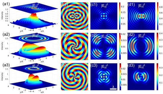
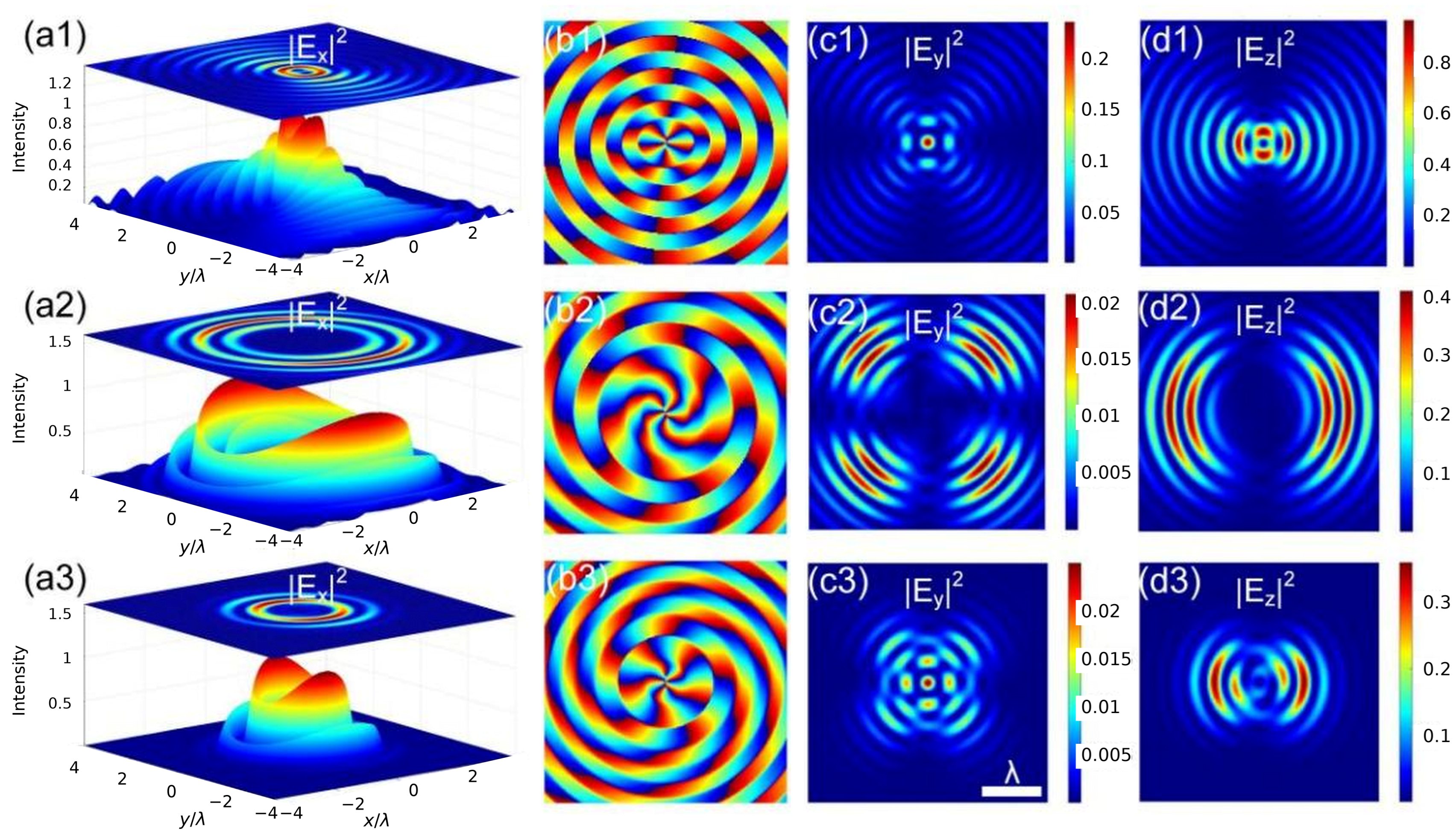
Figure 2 retains the original spatial illustrations for b = 0.1, 0.3 and 0.5, with f = 6 mm, G = 0.8, κ = 0.5, Cin = −Cout = 1100 m−2, rin = 0.8 mm, rout = 1.6 mm and rk1 = rk2 = 0. The distribution factor changes the Airy–Gaussian pupil weighting and focal ring structure [6,7,8,9,10,13]. The on-axis vortex pair preserves the scalar pupil symmetry, whereas x-polarized vector focusing produces distinct Ex, Ey and Ez patterns. Individually normalized spatial panels illustrate morphology. The original absolute-phase display is retained with its explicit plotting convention; it is not used to infer an additional physical vortex order.
Figure 2.
Original spatial illustrations. (a) Three-dimensional Ex intensity for (a1) b = 0.1, (a2) b =0.3 and (a3) b =0.5; (b) original phase display following the original plotting convention for (b1) b = 0.1, (b2) b =0.3 and (b3) b =0.5; and (c) Two-dimensional distributions of the transverse electric-field intensity Ey for (c1) b = 0.1, (c2) b =0.3 and (c3) b =0.5; (d) the longitudinal electric-field intensity Ez for (d1) b = 0.1, (d2) b =0.3 and (d3) b =0. The spatial intensity color scales are normalized display values. The original phase routine displays Arg[(Ex + iEy)exp(i3φ)]; this plotting phase is retained for consistency with the original figure and is not interpreted as an additional physical pupil vortex. f = 6 mm, G = 0.8, κ = 0.5, Cin = −Cout = 1100 m−2, rin = 0.8 mm, rout = 1.6 mm and rk1 = rk2 = 0. Common wavelength, NA, polarization and vortex orders are stated in Section 2.
3.2. Effect of the Scale Factor on the Focal Field
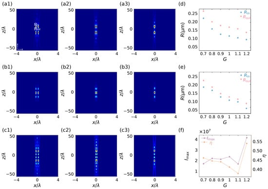
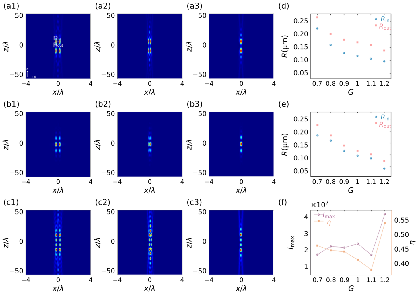
Figure 3a–c compares the x–z component maps for G = 0.8, 1.0 and 1.2. This family uses f = 6 mm, b = 0.2, κ = 0.5, Cin = −Cout = 1100 m−2, rin = 0.3R = 1.71 mm, rout = 0.6R = 3.42 mm and rk1 = rk2 = 0. Changing G modifies pupil weighting and radial interference [10,11,12,13]. Figure 3d,e gives the transverse threshold radii for Ex and Ez, respectively; Figure 3f gives the Ez peak and longitudinal peak ratio. These measures describe the redistribution of the focal field without establishing a universal critical value at G = 1.1.
Figure 3.
Scale-factor dependence. (a) Intensity distribution of Ex in the x–z plane for (a1) G = 0.8, (a2) G = 1.0 and (a3) G =1.2; (b) Intensity distribution of Ey in the x–z plane for (b1) G = 0.8, (b2) G = 1.0 and (b3) G =1.2; (c) Intensity distribution of Ey in the x–z plane for (c1) G = 0.8, (c2) G = 1.0 and (c3) G =1.2; (d,e) Ex and Ez transverse threshold radii Rin and Rout; (f) Ez peak Imax and longitudinal peak ratio η. Curves sample G = 0.7–1.2 in steps of 0.1 and retain the original amplitude normalization. f = 6 mm, b = 0.2, κ = 0.5, Cin = −Cout = 1100 m−2, rin = 1.71 mm, rout = 3.42 mm and rk1 = rk2 = 0.
3.3. Effect of Vortex Displacement on the Focal Field
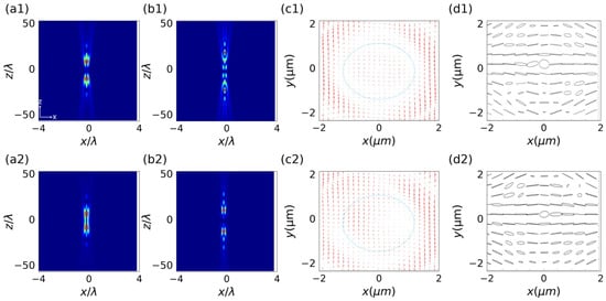
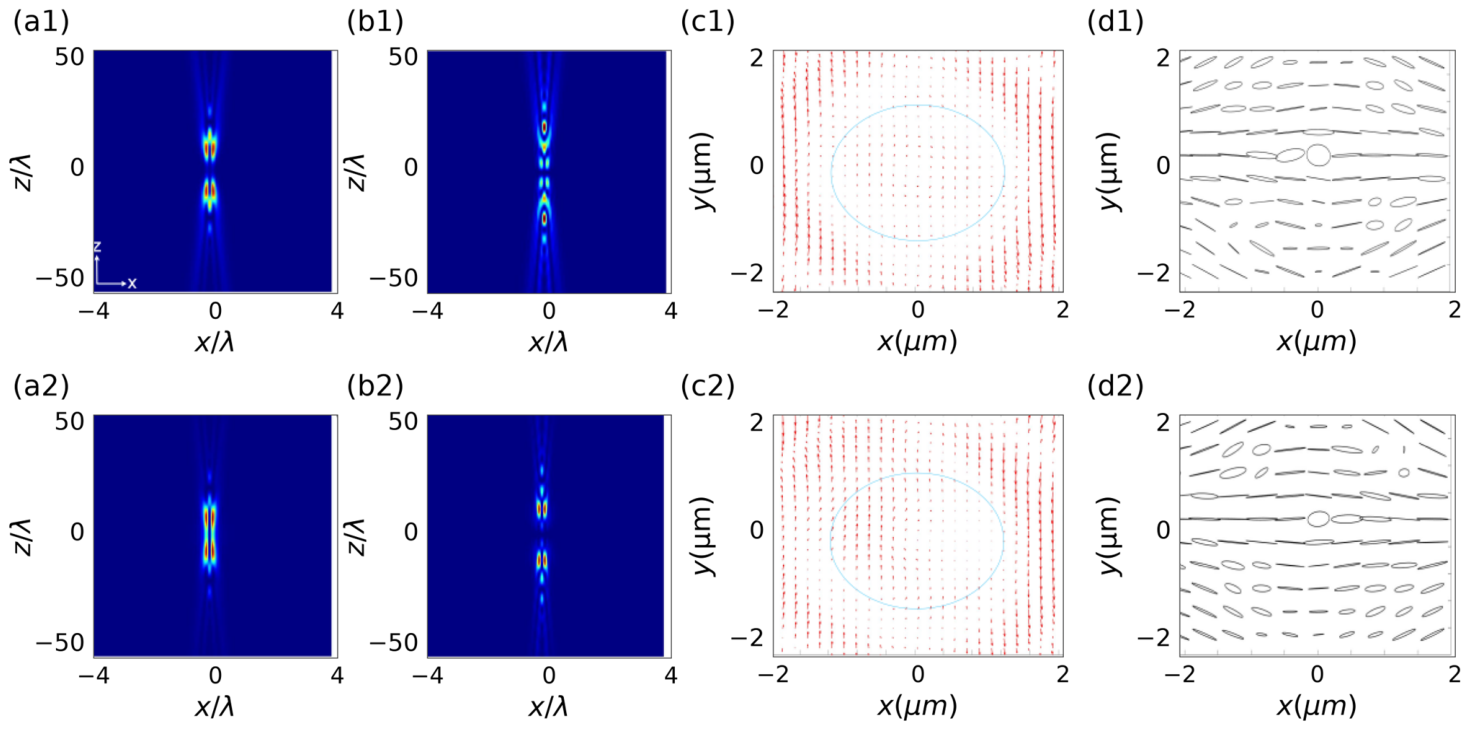
Figure 4 retains the original component, spin and polarization illustrations for f = 6 mm, b = 0.5, G = 0.8, κ = 0.5, Cin = −Cout = 1100 m−2, rin = 0.8 mm and rout = 1.6 mm. In Figure 4a, rk1 = rk2 changes from 0 to 0.3R; in Figure 4b, it changes from 0 to 0.5R. The two singularities move in opposite transverse directions and reshape the focal branches. Figure 4c compares spin orientation for rk1 = 0 and 0.3R with rk2 = 0. Figure 4d shows polarization ellipses for (rk1,rk2) = (0.3R,0) and (0,0.5R). The arrows project a three-dimensional spin direction, and the ellipses illustrate local orientation and ellipticity [22,23,24,25,26,31,32]. These vector-field changes do not by themselves establish a measurable particle torque.
Figure 4.
Original vortex-displacement illustrations. (a) Spatial distribution of Ex for (a1) rk1 = rk2 = 0 and (a2) rk1 = rk2 = 0.3R; (b) Spatial distribution of Ez for (b1) rk1 = rk2 = 0 and (b2) rk1 = rk2 =0.5R. (c) Spin-direction projections for (c1) rk1 = 0 and (c2) rk1 =0.3R with rk2 = 0. (d) Polarization ellipses for (d1) (rk1,rk2) = (0.3R,0) and (d2) (rk1,rk2) = (0,0.5R). R = f sinα = 5.7 mm. f = 6 mm, b = 0.5, G = 0.8, κ = 0.5, Cin = −Cout = 1100 m−2, rin = 0.8 mm and rout = 1.6 mm. Spatial maps retain their original normalization and appearance; spin and ellipse panels illustrate local orientation.
3.4. Effect of the Optical Distribution Factor on Spin Density and Relative Gouy Phase
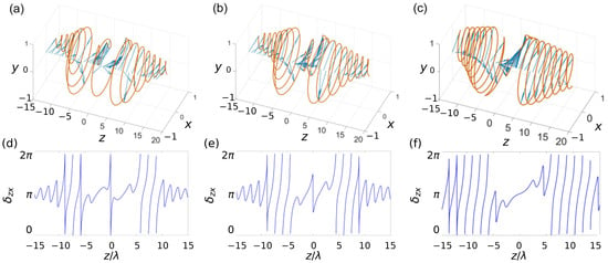
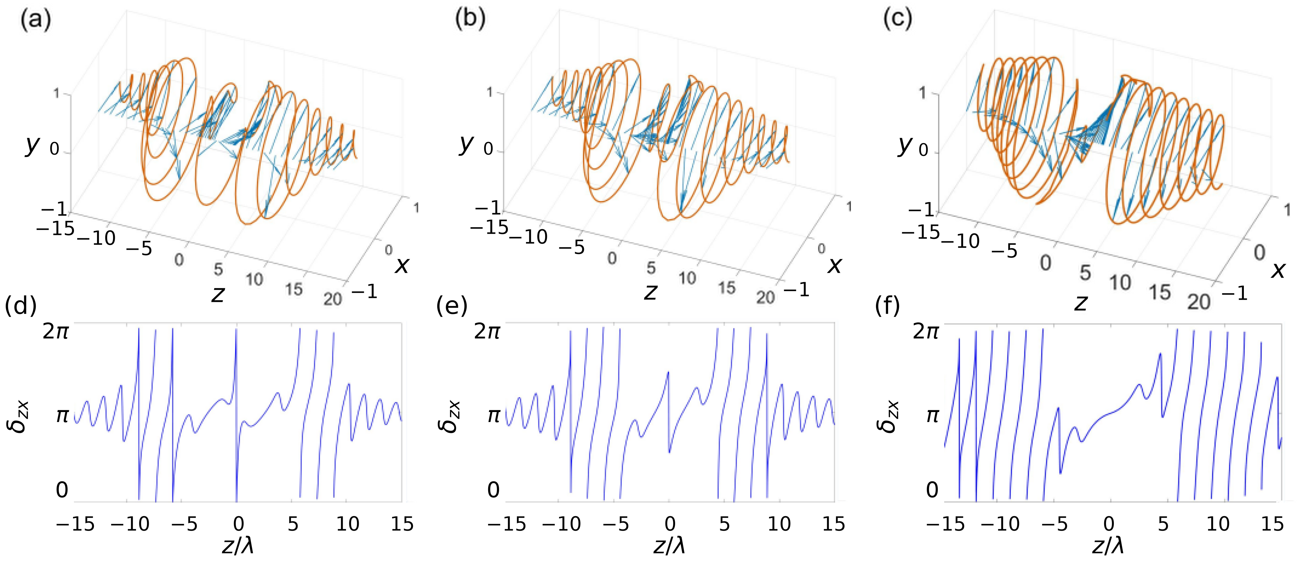
Figure 5 retains the original spin-direction trajectories and relative-phase curves for b = 0.3, 0.5 and 0.7. The settings are f = 6 mm, G = 0.8, κ = 0.5, Cin = −Cout = 1100 m−2, rin = 0.8 mm, rout = 1.6 mm, rk1 = 0.3R and rk2 = 0. The transverse spin components vary along z as Ex, Ey and Ez change in amplitude and relative phase. The b = 0.3 phase is not globally monotonic. The displayed phase is wrapped modulo 2π, so a branch jump is a representation change rather than necessarily a physical discontinuity. Relative phase can be evaluated as Arg(Ez Ex*) modulo 2π and is undefined when either component vanishes. Accordingly, the curves support local phase variation and spin-texture control [22,23,24,25], rather than a claim of global monotonicity or a phase winding inferred across zeros.
Figure 5.
Original spin trajectories and relative-phase curves for b = 0.3, 0.5 and 0.7, left to right. (a–c) Three-dimensional spin-direction trajectories and transverse arrows; the vertical coordinate is position z/λ. (d–f) Relative phase δzx displayed modulo 2π. Branch jumps do not by themselves indicate field discontinuities; relative phase is undefined at a zero of either component. f = 6 mm, G = 0.8, κ = 0.5, Cin = −Cout = 1100 m−2, rin = 0.8 mm, rout = 1.6 mm, rk1 = 0.3R and rk2 = 0. All original spatial and phase panels are retained.
3.5. Effect of the Hyperbolic Modulation Coefficient on the Focal Field
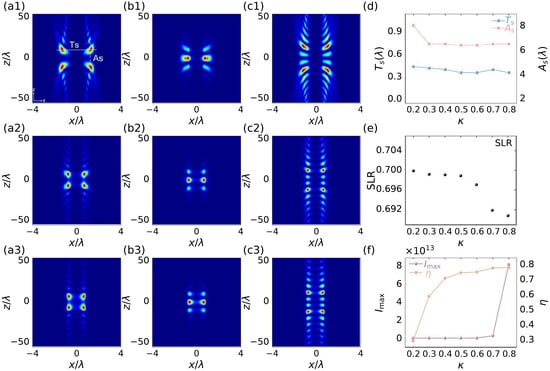
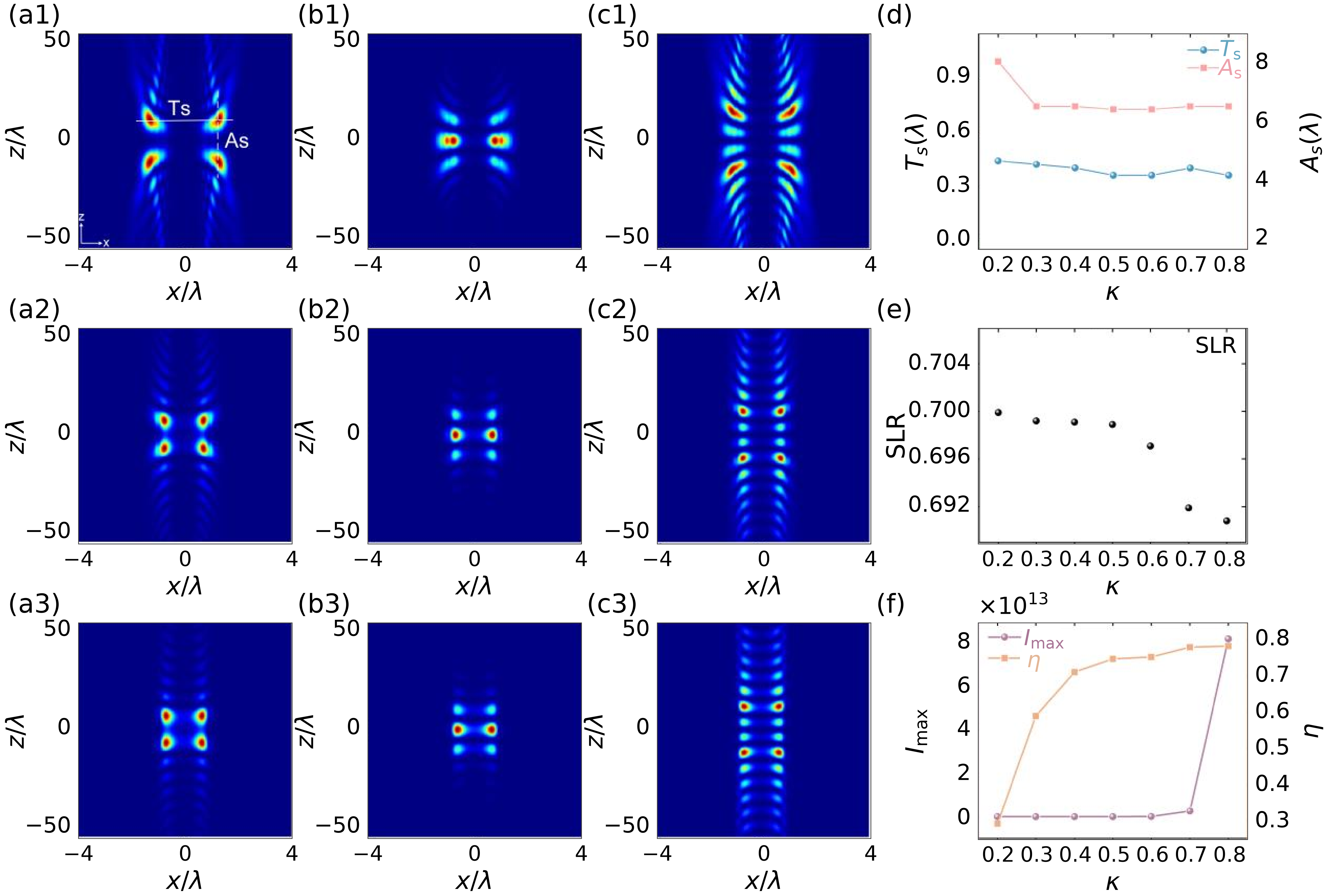
Figure 6 shows the hyperbolic-modulation dependence for f = 6 mm, b = 0.1, G = 0.8, Cin = −Cout = 1100 m−2, rin = 0.8 mm, rout = 1.6 mm and rk1 = rk2 = 0. The maps use κ = 0.2, 0.5 and 0.8; the curves sample 0.2–0.8 in steps of 0.1. Outer-ring amplitude weighting redistributes the focal peaks and increases the longitudinal peak ratio. The original threshold-based SLR statistic is described in Section 2 and is not interpreted as proof of physical sidelobe suppression [12,13,15,16,33].
Figure 6.
Hyperbolic-modulation dependence. Columns (a): Spatial distribution of Ex for (a1) κ = 0.2, (a2) κ = 0.5 and (a3) κ = 0.8; (b) Spatial distribution of Ey for (b1) κ = 0.2, (b2) κ = 0.5 and (b3) κ = 0.8; (c) Spatial distribution of Ez for (c1) κ = 0.2, (c2) κ = 0.5 and (c3) κ = 0.8; (d) Ex transverse and axial widths Ts and As, in λ; (e) threshold-based Ez SLR statistic defined in Section 2; (f) Ez peak Imax and longitudinal peak ratio η. Curves sample κ = 0.2–0.8 in steps of 0.1 and retain the original amplitude normalization. f = 6 mm, b = 0.1, G = 0.8, Cin = −Cout = 1100 m−2, rin = 0.8 mm, rout = 1.6 mm and rk1 = rk2 = 0.
3.6. Effect of the Radial-Chirp Coefficients on the Focal Field
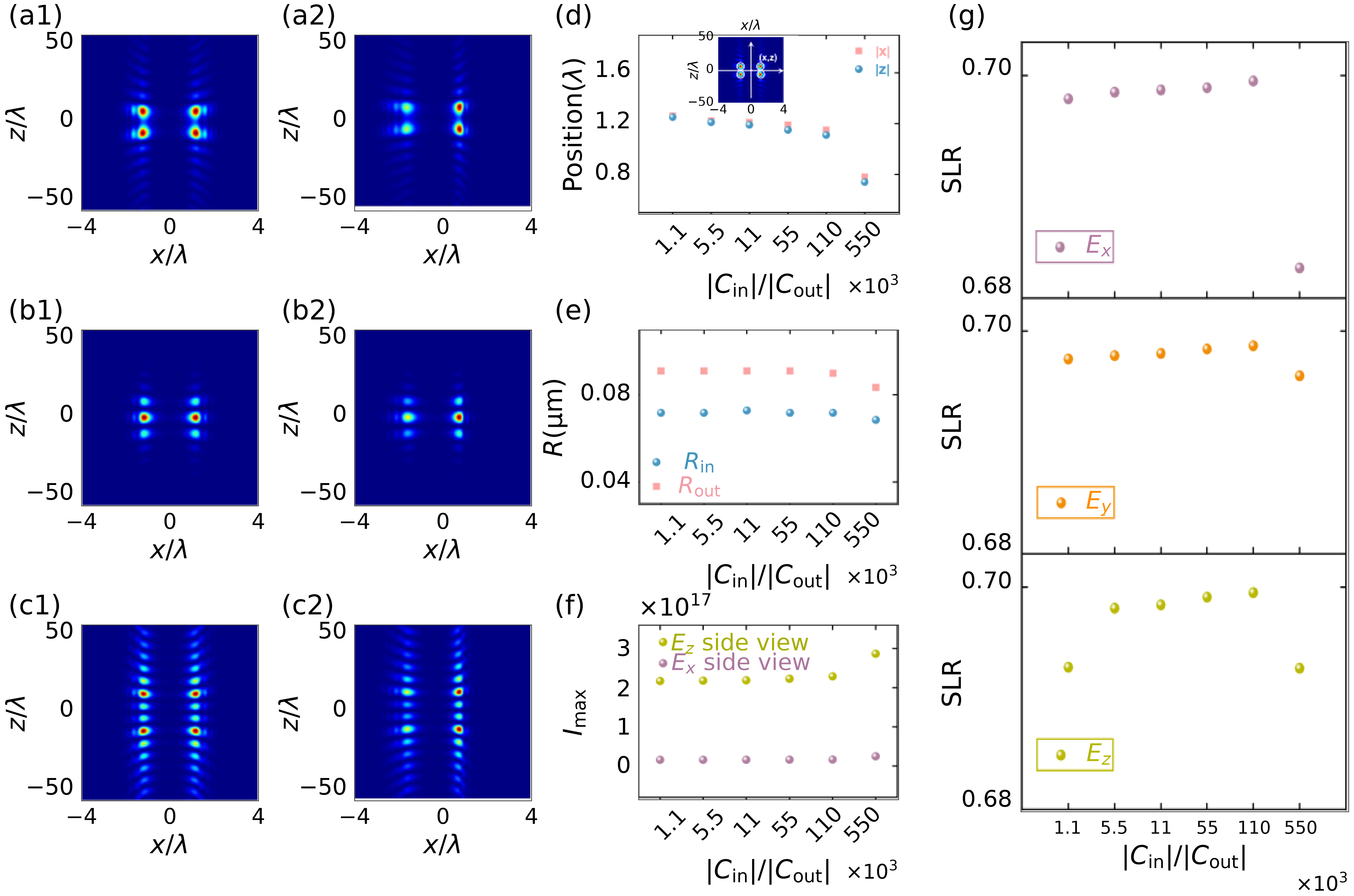
Figure 7 compares opposite radial chirps for f = 9 mm = 3w0, b = 0.1, G = 0.8, κ = 0.8, rin = 0.8 mm, rout = 1.6 mm and rk1 = rk2 = 0. The maps use |C| = 1100 and 550,000 m−2; the six curve samples use 1100, 5500, 11,000, 55,000, 110,000 and 550,000 m−2, with Cin = C and Cout = −C. The radial phases reshape the focal distribution and component balance [10,12,15,33]. The focal-coordinate, threshold-radius and peak-intensity plots demonstrate this redistribution. The SLR panels use the threshold statistic defined in Section 2 rather than a physical peak-sidelobe ratio.
Figure 7.
Opposite radial chirps. (a) Spatial distribution of Ex for (a1) |C| = 1100 and (a2) 550,000 m−2; (b) Spatial distribution of Ey for (b1) |C| = 1100 and (b2) 550,000 m−2; (c) Spatial distribution of Ey for (c1) |C| = 1100 and (c2) 550,000 m−2; (d) Ex peak coordinates and the original inset; (e) Ex threshold radii Rin and Rout; (f) Ex and Ez peaks; (g) component threshold-based SLR statistics. Six samples use |C| = 1100, 5500, 11,000, 55,000, 110,000 and 550,000 m−2, with Cin = C and Cout = −C. The original intensity normalization is retained. f = 9 mm, b = 0.1, G = 0.8, κ = 0.8, rin = 0.8 mm, rout = 1.6 mm and rk1 = rk2 = 0.
4. Optical Forces on Rayleigh Particles
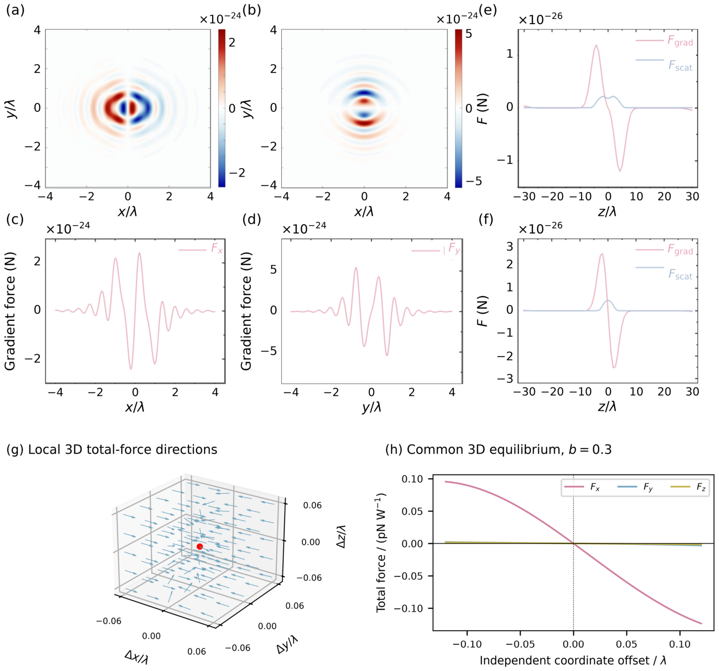
Figure 8a–f presents the original transverse gradient-force maps, transverse force cuts and axial gradient and scattering contributions for f = 3 mm = w0, G = 0.8, κ = 0.5, Cin = −Cout = 1100 m−2, rin = 0.8 mm, rout = 1.6 mm and rk1 = rk2 = 0. Figure 8g shows the three-dimensional total-force directions near the selected b = 0.3 equilibrium, marked in red. Arrow lengths are normalized to emphasize direction. Figure 8h shows the corresponding Fx, Fy and Fz cuts: one coordinate is varied at a time while the other two remain fixed at the same equilibrium. Each component vanishes at zero displacement and reverses sign across it, consistent with a local restoring response along the three coordinate cuts. These two panels complement the separate force distributions in Figure 8a–f.
Figure 8.
Optical forces. (a,b) Original transverse gradient-force maps; (c,d) original x and y gradient-force cuts; (e,f) original axial gradient and scattering contributions for b = 0.1 and 0.3. Original panels a–f retain their display scales and do not by themselves establish a common three-dimensional equilibrium. (g) Three-dimensional total-force directions near the b = 0.3 equilibrium, with normalized arrows and a red equilibrium marker. (h) Three total-force component cuts through the same equilibrium, with the other coordinates held fixed; offsets are measured from that point. Only the new curves in h use the corrected force normalization, in pN W−1. f = 3 mm, G = 0.8, κ = 0.5, Cin = −Cout = 1100 m−2, rin = 0.8 mm, rout = 1.6 mm, rk1 = rk2 = 0, rp = 20 nm, np = 1.59 and nm = 1.
5. Conclusions
We introduced an AHC-DRAGVB with asymmetric radial phase and amplitude modulation and analyzed its tightly focused field, spin texture and Rayleigh-particle forces using the Richards–Wolf formalism. G modifies focal interference and longitudinal weighting; vortex displacement reshapes the focal pattern, spin orientation and polarization; and b changes local relative-phase evolution. The hyperbolic coefficient κ changes longitudinal peak weighting, while opposite chirps tune focal position and component balance. Additional three-dimensional total-force directions and coordinate cuts illustrate the local restoring response near a common equilibrium for b = 0.3. These results provide a basis for further study of structured-light manipulation.
Author Contributions
Conceptualization, T.D. and W.L.; methodology, T.D. and C.Y.; software, T.D. and Q.Z.; validation, Q.Z., Z.Z. and X.W.; formal analysis, T.D. and C.Y.; investigation, T.D., Q.Z., Z.Z. and X.W.; visualization, T.D., Z.Z. and X.W.; writing—original draft preparation, T.D.; writing—review and editing, C.Y. and W.L.; supervision, W.L.; project administration, W.L.; funding acquisition, T.D. All authors have read and agreed to the published version of the manuscript.
Funding
This research was supported by the National Natural Science Foundation of China (Grant No. 12604652) and the Wuxi University Research Start-up Fund for Introduced Talents (Grant No. 550225101).
Institutional Review Board Statement
Not applicable.
Informed Consent Statement
Not applicable.
Data Availability Statement
The data supporting the findings of this study are available from the corresponding author upon reasonable request.
Conflicts of Interest
The authors declare no conflicts of interest.
References
- Ashkin, A. Acceleration and trapping of particles by radiation pressure. Phys. Rev. Lett. 1970, 24, 156–159. [Google Scholar] [CrossRef] [Scilit]
- Ashkin, A.; Dziedzic, J.M.; Bjorkholm, J.E.; Chu, S. Observation of a single-beam gradient force optical trap for dielectric particles. Opt. Lett. 1986, 11, 288–290. [Google Scholar] [CrossRef] [Scilit] [PubMed]
- Yang, Y.; Ren, Y.X.; Chen, M.; Arita, Y.; Rosales-Guzmán, C. Optical trapping with structured light: A review. Adv. Photonics 2021, 3, 034001. [Google Scholar] [CrossRef] [Scilit]
- Bustamante, C.J.; Chemla, Y.R.; Liu, S.; Wang, M.D. Optical tweezers in single-molecule biophysics. Nat. Rev. Methods Primers 2021, 1, 25. [Google Scholar] [CrossRef] [Scilit]
- Forbes, A.; de Oliveira, M.; Dennis, M.R. Structured light. Nat. Photonics 2021, 15, 253–262. [Google Scholar] [CrossRef] [Scilit]
- Siviloglou, G.A.; Christodoulides, D.N. Accelerating finite energy Airy beams. Opt. Lett. 2007, 32, 979–981. [Google Scholar] [CrossRef] [Scilit] [PubMed]
- Siviloglou, G.A.; Broky, J.; Dogariu, A.; Christodoulides, D.N. Observation of accelerating Airy beams. Phys. Rev. Lett. 2007, 99, 213901. [Google Scholar] [CrossRef] [Scilit] [PubMed]
- Papazoglou, D.G.; Efremidis, N.K.; Christodoulides, D.N.; Tzortzakis, S. Observation of abruptly autofocusing waves. Opt. Lett. 2011, 36, 1842–1844. [Google Scholar] [CrossRef] [Scilit] [PubMed]
- Efremidis, N.K.; Chen, Z.; Segev, M.; Christodoulides, D.N. Airy beams and accelerating waves: An overview of recent advances. Optica 2019, 6, 686–701. [Google Scholar] [CrossRef] [Scilit]
- Ni, J.; Kong, L.; Yan, Y.; Qiu, J.; Peng, L.; Luo, K.; Chen, M.; Han, P.; Gu, M.; Liu, D. Autofocusing capabilities of double-ring circular Airy Gaussian beams and their application in particle manipulation. Opt. Express 2024, 32, 44908–44917. [Google Scholar] [CrossRef] [Scilit]
- Chen, J.; Gao, H.; Liu, Z.; Wang, F.; Cai, Y.; Zhou, G. Multi-modal particle trapping via a vortex-loaded dual-ring Airy-Gaussian beam. Photonics Res. 2026, 14, B140–B157. [Google Scholar] [CrossRef] [Scilit]
- Wei, S.; Tu, J.; Lu, Z.; Wang, X.; Li, Z.; Wang, G.; Deng, D. Evolution and particle trapping dynamics of circular Pearcey-Airy Gaussian vortex beams in tightly focused systems. Opt. Express 2023, 31, 27843–27857. [Google Scholar] [CrossRef] [Scilit] [PubMed]
- Zhang, G.-B.; Gao, X.-Z.; Sun, X.-F.; Ma, R.; Wang, Y.; Pan, Y. Airy-Gaussian vector beam and its application in generating flexible optical chains. Opt. Express 2023, 31, 30319–30331. [Google Scholar] [CrossRef] [Scilit] [PubMed]
- Zheng, Y.; Chen, J.; Gao, H.; Liu, Z.; Wang, F.; Cai, Y.; Zhou, G. Sculpting the focusing morphologies of tightly focused dual-ring Airy-Gaussian beam via vortex. Chaos Solitons Fractals 2026, 208, 118387. [Google Scholar] [CrossRef] [Scilit]
- Mo, Z.; Jiang, J.; Wei, Q.; Xu, D.; Yang, H.; Huang, H.; Wu, Y.; Liu, H.; Shui, L.; Deng, D. Multiple and off-axis optical bottles from the chirped circular Pearcey Gaussian vortex beams. Opt. Express 2022, 30, 1762–1772. [Google Scholar] [CrossRef] [Scilit] [PubMed]
- Wu, Z.; Zhao, J.; Dou, J.; Liu, J.; Jing, Q.; Li, B.; Hu, Y. Optical trapping of multiple particles based on a rotationally-symmetric power-exponent-phase vortex beam. Opt. Express 2022, 30, 42892–42901. [Google Scholar] [CrossRef] [Scilit] [PubMed]
- Zhen, W.; Wang, X.-L.; Ding, J.; Wang, H.-T. Controlling the symmetry of the photonic spin Hall effect by an optical vortex pair. Phys. Rev. A 2023, 108, 023514. [Google Scholar] [CrossRef] [Scilit]
- Zhen, W.; Wang, X.-L.; Ding, J.; Wang, H.-T. Revisiting physical mechanism of longitudinal photonic spin splitting and Goos–Hänchen shift. New J. Phys. 2024, 26, 013045. [Google Scholar] [CrossRef] [Scilit]
- Zhen, W.; Ren, Z.-C.; Wang, X.-L.; Ding, J.; Wang, H.-T. Polarization structure transition of C-point singularities upon reflection. Sci. China Phys. Mech. Astron. 2025, 68, 244211. [Google Scholar] [CrossRef] [Scilit]
- Zhen, W.; Qing, Z.; Yan, W.; Ren, Z.-C.; Wang, X.-L.; Wang, H.-T.; Ding, J.; Shen, Y. Reconfiguring optical skyrmion topology in free space. Optica 2026, 13, 188–194. [Google Scholar] [CrossRef] [Scilit]
- Richards, B.; Wolf, E. Electromagnetic diffraction in optical systems, II. Structure of the image field in an aplanatic system. Proc. R. Soc. Lond. A 1959, 253, 358–379. [Google Scholar] [CrossRef] [Scilit]
- Bliokh, K.Y.; Rodríguez-Fortuño, F.J.; Nori, F.; Zayats, A.V. Spin–orbit interactions of light. Nat. Photonics 2015, 9, 796–808. [Google Scholar] [CrossRef] [Scilit]
- Neugebauer, M.; Bauer, T.; Aiello, A.; Banzer, P. Measuring the transverse spin density of light. Phys. Rev. Lett. 2015, 114, 063901. [Google Scholar] [CrossRef] [Scilit] [PubMed]
- Eismann, J.S.; Nicholls, L.H.; Roth, D.J.; Alonso, M.A.; Banzer, P.; Rodríguez-Fortuño, F.J.; Zayats, A.V.; Nori, F.; Bliokh, K.Y. Transverse spinning of unpolarized light. Nat. Photonics 2021, 15, 156–161. [Google Scholar] [CrossRef] [Scilit]
- Chen, Y.; Wang, F.; Dong, Z.; Cai, Y.; Norrman, A.; Gil, J.J.; Friberg, A.T.; Setälä, T. Structure of transverse spin in focused random light. Phys. Rev. A 2021, 104, 013516. [Google Scholar] [CrossRef] [Scilit]
- Ni, J.; Huang, C.; Zhou, L.-M.; Gu, M.; Song, Q.; Kivshar, Y.; Qiu, C.-W. Multidimensional phase singularities in nanophotonics. Science 2021, 374, eabj0039. [Google Scholar] [CrossRef] [Scilit] [PubMed]
- Liang, Y.; Su, Y.; Li, J.; Yang, C. Optical trapping of Rayleigh particles based on four-petal Gaussian vortex beams. J. Opt. Soc. Am. A 2022, 39, 1378–1384. [Google Scholar] [CrossRef] [Scilit] [PubMed]
- Harada, Y.; Asakura, T. Radiation forces on a dielectric sphere in the Rayleigh scattering regime. Opt. Commun. 1996, 124, 529–541. [Google Scholar] [CrossRef] [Scilit]
- Chaumet, P.C.; Nieto-Vesperinas, M. Time-averaged total force on a dipolar sphere in an electromagnetic field. Opt. Lett. 2000, 25, 1065–1067. [Google Scholar] [CrossRef] [Scilit] [PubMed]
- Canaguier-Durand, A.; Cuche, A.; Genet, C.; Ebbesen, T.W. Force and torque on an electric dipole by spinning light fields. Phys. Rev. A 2013, 88, 033831. [Google Scholar] [CrossRef] [Scilit]
- Brimis, A.; Makris, K.G.; Papazoglou, D.G. Optical vortices shape optical tornados. Opt. Express 2023, 31, 27582–27593. [Google Scholar] [CrossRef] [Scilit] [PubMed]
- Bai, Y.; Lv, H.; Fu, X.; Yang, Y. Vortex beam: Generation and detection of orbital angular momentum. Chin. Opt. Lett. 2022, 20, 012601. [Google Scholar] [CrossRef] [Scilit]
- Yang, S.; Yu, P.; Wu, J.; Zhang, X.; Xu, Z.; Man, Z.; Ge, X.; Fu, S.; Lei, C.; Chen, C.; et al. Propagation dynamics of the controllable circular Airyprime beam in the Kerr medium. Opt. Express 2023, 31, 35685–35696. [Google Scholar] [CrossRef] [Scilit] [PubMed]
Disclaimer/Publisher’s Note: The statements, opinions and data contained in all publications are solely those of the individual author(s) and contributor(s) and not of MDPI and/or the editor(s). MDPI and/or the editor(s) disclaim responsibility for any injury to people or property resulting from any ideas, methods, instructions or products referred to in the content. |
© 2026 by the authors. Licensee MDPI, Basel, Switzerland. This article is an open access article distributed under the terms and conditions of the Creative Commons Attribution (CC BY) license.