


Abstract
Underwater optical communication and imaging are degraded by absorption, scattering, refractive index fluctuations, interface aberrations, and platform motion. These impairments require different measurements and corrective actions. This critical narrative review evaluates physical wavefront correction, including Shack–Hartmann sensing with deformable-mirror or spatial-light-modulator control, sensorless optimization, phase conjugation, and learning-assisted estimation, alongside aperture averaging, beam tracking, and computational or link-layer adaptation. An impairment-to-adaptation framework connects the dominant disturbance to an available observable, an intervention, a task-specific metric, a validation setting, and a deployment constraint. Evidence from analytical studies, controlled-water tests, integrated prototypes, and field systems is interpreted separately; adjacent communication methods are not conflated with adaptive optics. A quantitative design example illustrates the roles of coherence time, sensing-to-actuation delay, and net communication benefit. Within the reviewed corpus, wavefront characterization and controlled-water correction are documented more extensively than moving-platform, open-water, closed-loop adaptive optics, for which independent validation remains limited. The review provides practical criteria for selecting, combining, and evaluating correction techniques without implying a universal performance ranking.
1. Introduction
Optical links and cameras offer bandwidth and spatial resolution that are difficult to obtain with acoustic systems over short underwater ranges. The same water column that enables compact high-rate links also imposes wavelength-dependent absorption, particle scattering, refractive index fluctuations, bubbles, flow, interface distortion, and pointing errors. These processes act on different parts of the signal. Absorption reduces the photon budget. Scattering changes radiance, contrast, and temporal spread. Turbulence perturbs phase and, after propagation, produces beam wander, scintillation, blur, and modal crosstalk. A correction architecture must therefore begin with the information that remains in the collected field, not with a preferred algorithm.
Reviews of underwater optical wireless communication provide broad context for channel loss, terminal design, networking, and localization [1,2,3,4]. Turbulence-focused reviews synthesize propagation statistics and mitigation [5], while spatial-mode reviews address generation, multiplexing, and detection [6,7]. A recent focused review of adaptive optics in underwater optical communication discusses turbulence, Shack–Hartmann and sensorless approaches, machine learning correction, and future real-time and cross-media directions [8]. The present contribution is complementary rather than a claim of priority for individual methods: it organizes the evidence around correctability boundaries and explicitly links impairment, observable, intervention layer, performance metric, validation setting, timing, deployment constraint, and failure criteria.
Adaptive optics is used here in a precise sense. Classical adaptive optics measures or estimates the incoming phase and drives a corrective element such as a deformable mirror or spatial light modulator. Sensorless adaptive optics optimizes a focal-plane, image, power, or coupling metric without a separate wavefront sensor. Wavefront shaping controls an input or corrective field through a complex medium. Aperture averaging changes collection statistics but does not restore phase. Computational restoration acts after detection. A machine learning classifier can infer a symbol or turbulence class from a distorted pattern without reconstructing the transmitted field. Adaptive modulation, beam steering, relays, and reconfigurable paths alter the communication strategy or geometry. These interventions may operate together, but they are not interchangeable.
In a practical wavefront-correction loop, a beacon or received field is sampled by a wavefront sensor (for example, a Shack–Hartmann sensor), phase error is reconstructed, and a deformable mirror or spatial light modulator (SLM) applies a compensating command. A steering mirror addresses the beam angle rather than higher-order aberration. Sensorless approaches instead perturb the corrector and optimize the detected intensity, coupling, or image quality. These designs must be compared using the photon budget, corrected spatial modes, actuator stroke, sensing and settling times, and residual error at the application receiver.
We propose an impairment-to-adaptation framework to support conditional engineering decisions. Its novelty is not a new AO actuator or reconstruction algorithm; it is the explicit decision sequence linking six elements—impairment, observable, intervention, performance metric, validation setting, and deployment constraint—while enforcing boundaries between phase correction and adjacent collection, tracking, computational, coding, and path-control actions. In contrast to method-centered taxonomies, the framework asks first what information survives the channel and then whether a candidate intervention can act within the disturbance dynamics and improve the intended task after sensing and control overhead. Section 6 applies the sequence to worked terminal designs, including a quantitative illustrative case, and Section 8 converts the resulting gaps into benchmark and architecture recommendations. These examples reflect the authors’ synthesis and do not constitute new experimental evidence.
Three review questions structure the synthesis. First, which underwater optical degradations are physically correctable by wavefront control, and which require passive, computational, communication-level, or geometric responses? Second, how do classical adaptive optics, sensorless methods, learning-assisted reconstruction, and adjacent adaptation layers compare in their observables, hardware requirements, metrics, and evidence maturity? Third, which evidence and timing constraints currently prevent integration into deployable marine optical terminals? The article addresses these questions across communication, structured-light transmission, imaging, and optical sensing while keeping underwater wavefront control at the center.
Scope of evidence: This article is a critical narrative review, not a PRISMA-compliant systematic review or meta-analysis. The literature synthesis draws on 87 structured core references (74 records retained from deduplicated Scopus searches conducted on 14 September 2026 and 13 targeted background references) and six supplementary 2025–2026 references, giving 93 cited sources. The searches, exclusion decisions, reinstatement audit, provenance, and representative study-level extraction are documented in Supplementary Data Sheets S1–S4. A single reviewer screened the Scopus results; numerical outcomes from heterogeneous studies are not pooled. The analysis therefore distinguishes models, controlled-water studies, prototypes, and field evidence rather than claiming an exhaustive or quantitative comparative ranking. Table 1 summarizes the scope of representative previous reviews and highlights the distinct contribution of the present impairment-to-adaptation framework.
Table 1.
Positioning relative to the representative prior literature. The entries summarize the primary emphasis used in this manuscript and do not imply that a cited review excludes topics not listed. This table is an original synthesis prepared by the authors from the cited literature; no previously published table, figure, or artwork is reproduced or adapted.
2. Physical Regimes and Correctability
2.1. Radiometric Loss and Scattering
For an approximately collimated ballistic component, a useful engineering approximation is Pᵣ = Pt η G exp[−c(λ)L], with c(λ) = a(λ) + b(λ), where a and b are absorption and scattering coefficients, L is water-path length, and η and G represent throughput and geometric collection. This is not an exact radiative-transfer model: it approximates the ballistic or effectively collected component and can fail when multiple scattering, field-of-view effects, or path-dependent radiance redistribution, dominate. Absorption removes energy; scattering redistributes direction and arrival time. Scattered fields may remain coherent and interfere, while finite exposure, spatial averaging, broadband illumination, and ambient light can create an effectively incoherent background. Correction is limited by the information reaching the relevant sensing and correction planes [1,5].
The extent to which scattering can be corrected depends on the scattering regime and the available measurements. Weak forward scattering may broaden the point-spread function while preserving enough coherent structure for phase-sensitive correction or computational inversion. Strong multiple scattering mixes paths and reduces the memory of the incident field. A transmission matrix or wavefront-shaping method can focus through a static complex medium if calibration remains valid, but a moving water volume, bubbles, and suspended matter can decorrelate that calibration. Post-detection restoration may improve visibility or task performance without restoring the physical field. We therefore distinguish optical field correction from de-scattering and image enhancement, even when both improve the same image.
2.2. Refractive Index Fluctuations
Temperature and salinity fluctuations change the refractive index of water over a range of spatial and temporal scales. Oceanic spectra extend atmospheric turbulence concepts by including temperature, salinity, and their co-spectrum. Analytical studies frequently combine a Nikishov-type spectrum with Rytov propagation, lognormal irradiance statistics, aperture filtering, and idealized removal of Zernike modes. These models are valuable for sensitivity analysis, but their predictions inherit weak-fluctuation, stationarity, and spectral assumptions. Natural water may contain anisotropic gradients, intermittent mixing, driven flow, and simultaneous particulate scattering that are not represented by one phase screen.
The normalized scintillation index is σ_I2 = <I2>/<I>2 − 1. It measures temporal or ensemble fluctuation of intensity and is directly relevant to fade probability and direct-detection error performance. It does not identify the aberration modes that produced the fluctuation. Wavefront sensing adds spatial phase information, commonly expressed as φ(r,θ,t) = Σ a_j(t) Z_j(r,θ), where a_j are time-dependent modal coefficients. Removing low-order coefficients can reduce beam motion and improve focusing, although the relation between residual phase, aperture-averaged intensity, and BER depends on detector geometry and receiver processing.
Controlled-tank studies illustrate why simultaneous environmental and optical measurements matter [10,11,12,13,14,15,16,17,18,19,20,21]. A temperature difference or injected flow is not itself a complete turbulence descriptor. Experiments should report geometry, heat or mixing mechanism, path position, temperature and salinity fields, aperture, integration time, and optical statistics. Recent additions sharpen the distinction between observables. Mohammadi Razi [16] directly reconstructed underwater Rayleigh–Bénard wavefront distortion and analyzed Zernike-mode content; Avramov-Zamurovic et al. [17] forecast intensity evolution rather than phase; Jia et al. [18] estimated the turbulence state from beam images; and O’Malley et al. [21] compared phase-estimation routes in measured underwater convection. These studies support multi-observable characterization while showing that intensity prediction, classification, or phase estimation is not by itself wavefront correction.
2.3. Interfaces, Pointing, and Platform Motion
Air–water interfaces, dome ports, surface waves, and terminal misalignment can introduce deterministic and time-varying optical aberrations or geometric errors [22,23,24,25]. Some errors can be reduced through optical design or calibration, whereas others vary with interface motion, platform attitude, or propagation geometry [22,24,25]. Beam wander caused by turbulence can resemble pointing error at the receiver, but the appropriate control actions differ: a deformable mirror changes wavefront phase, whereas a fast-steering mirror, gimbal, or electronic steering system changes beam angle or line of sight [26]. Path switching changes the propagation route [27]. A terminal that confuses these disturbances can spend a wavefront-corrector stroke on an error that should be handled by tracking or geometry control.
In experiments, turbulence-induced beam motion and platform motion should be separated with synchronized observables rather than by received power alone. A practical dataset combines an inertial measurement unit (attitude and angular rate), a centroid or acquisition camera, wavefront-sensor tilt and higher-order coefficients, and received power. A rigid-body pointing model predicts the centroid component expected from measured platform attitude; the residual centroid and wavefront terms can then be tested for correlation with independently measured water disturbances. Cross-spectral coherence and time lag analysis are useful diagnostics, but frequency alone is not a universal separator because both platform motion and turbulence can occupy overlapping bands. The most defensible attribution therefore uses matched static-platform controls and synchronized inertial, centroid, phase, and power records [24,26,28,29].
2.4. Correctability Boundaries
For direct wavefront correction, the optical geometry must specify whether the aberration is measured at the receiver pupil or inferred from a guide field, whether the control plane is conjugate to the dominant distortion, and which spatial modes are actually correctable. For direct-detection links, tip/tilt control can recover aperture-coupling loss without requiring higher-order correction; coherent or single-mode receivers may require both pointing stabilization and residual phase compensation. These distinctions prevent phase-control claims from being inferred solely from received-power changes.
Three tests define a practical correctability boundary. First, the collected signal must retain information about the desired field; absorption and severe out-of-aperture scattering can fail this test. Second, the observable must be measured with a sufficient signal-to-noise ratio and spatial resolution. Third, the sensing, inference, command, and actuator cycle must complete before the relevant disturbance decorrelates. Together, these engineering criteria define the framework’s correctability gate; they do not constitute a new propagation law. Table 2 summarizes the principal underwater optical impairments, their observable effects, appropriate intervention strategies, and practical correctability boundaries.
Table 2.
Impairments, observables, interventions, and correctability boundaries.
3. The Impairment-to-Adaptation Framework
Figure 1 formalizes the proposed six-element impairment-to-adaptation framework. The framework begins with the dominant impairment and the observable available at the terminal. The same received-power fluctuation can originate from scintillation, pointing loss, bubbles, obstruction, or source instability, so an intervention should not be selected from one metric alone. The sequence then separates the intervention layer, task metric, validation setting, and deployment constraint before applying an explicit correctability and acceptance gate. This differs from a method taxonomy because it can reject an otherwise effective algorithm when the required observable is unavailable, the loop is too slow, or the task-level gain disappears after overhead.
Figure 1.
Impairment-to-adaptation framework for an underwater optical terminal. Six elements—impairment, observable, intervention, performance metric, validation setting, and deployment constraint—feed a correctability/acceptance gate. An intervention is retained only when the signal remains observable, the control cycle fits the channel dynamics, and the intended task improves after sensing loss, interruptions, processing, and actuation overhead.
The intervention layer defines what is changed. Physical adaptive optics changes phase or, in some architectures, phase and amplitude. Aperture and collection design change how the field is sampled. Sensorless control changes a corrector using an output metric. Computational inference estimates a phase, image, symbol, or channel state. Communication adaptation changes modulation, coding, symbol alphabet, or receiver gain. Beam steering and path control change geometry. One system may contain several layers, but each layer requires its own metric and failure criterion.
Metric selection follows the intended information product. The residual wavefront error and Strehl ratio are appropriate for phase and focusing. Scintillation and fade probability describe collected-power stability. Coupling efficiency is critical for coherent or single-mode receivers. Mode purity and crosstalk describe structured-light fidelity. BER and throughput test communication delivery. PSNR, SSIM, UIQM, contrast, localization error, and task accuracy describe different aspects of images and sensing. A gain in one metric cannot be assumed to transfer to another. For example, increased received power can coexist with poor modal orthogonality, and high classifier accuracy can coexist with a badly distorted wavefront.
The validation setting determines which claims can be tested but does not, by itself, establish study quality. For each claim, we ask whether the disturbance is characterized, the comparator is matched, repetitions are independent, uncertainty is quantified, and physical corrective action is demonstrated. Study-level evidence is considered separately from general claims: unresolved extraction fields are recorded as not reported, and model, laboratory, prototype, and field settings are not treated as interchangeable validation.
Deployment constraints complete the framework. Channel coherence time; sensor exposure; inference latency; corrector refresh rate; guide-source geometry; reciprocity; calibration drift; detector saturation; background light; and size, weight, power, cost, and cooling determine whether a method can operate on a marine platform. The framework therefore converts a list of algorithms into a design argument. It also provides a basis for assessing whether a study’s claims exceed the supporting evidence. A simulation can support feasibility, but it cannot establish field robustness. A tank experiment can demonstrate underwater operation, but it cannot establish endurance, biofouling tolerance, or performance under moving-platform conditions.
Scheme 1 illustrates a representative underwater adaptive-optics terminal architecture, highlighting the complementary roles of beam tracking and wavefront correction in compensating for different disturbances.
Scheme 1.
Representative underwater adaptive-optics terminal architecture. The wavefront-correction loop estimates phase and commands a deformable mirror or SLM, while a separate pointing/tracking loop uses centroid and/or inertial information to drive a fast steering mirror or gimbal. The two loops can cooperate but correct different disturbances; tracking stabilizes line of sight, whereas AO corrects wavefront distortion. The arrows indicate the sequential flow of the decision-making process, from identifying the dominant impairment and available observables to selecting an intervention, evaluating its performance, considering the validation setting and deployment constraints, and applying the final correctability and acceptance criteria.
4. Physical Wavefront Correction and Passive Mitigation
4.1. Modal Correction in Oceanic Turbulence
Classical underwater adaptive-optics studies often represent phase distortion with Zernike modes and calculate the effect of ideal low-order removal on scintillation, fade probability, SNR, BER, coupling, or capacity [31,34,35,36,37,38,39]. Related model studies include the correction of Hermite–Gaussian modes [40]. The experimental record must be distinguished by function and setting: low-order underwater imaging was proposed rather than demonstrated in [41]; Refs. [19,42] report wavefront sensing and characterization; Refs. [25,43] concern correction at or above an air–water interface; and Refs. [23,44,45] describe underwater or water-induced physical correction in controlled settings. Other investigations use active probing [32] or numerical and learned correction [46,47,48]. These results broaden the evidence beyond ideal modal removal, but they should not be pooled or described collectively as moving-platform, underwater, closed-loop AO demonstrations.
Toselli and Gladysz analyze the joint dependence of scintillation on ideal modal correction and aperture averaging [31]. Their modeled improvement is conditional on turbulence and collection geometry. Direct experimental work provides a complementary but heterogeneous picture. Li et al. [23] used phase conjugation under surface-wave turbulence and evaluated beam drift, scintillation, and SNR; Wiley et al. [32] characterized an underwater turbulence emulator and actively searched optical channel states to improve transmission through the disturbed medium. These mechanisms are physically different from deformable-mirror Zernike correction, so their gains should be interpreted within their own baseline and disturbance definitions rather than ranked against ideal AO models.
BER- and capacity-oriented analyses reach consistent qualitative conclusions across BPSK-SIM, pulse-position modulation, and channel-capacity models [34,35,36,39]. Tilt correction can contribute strongly when beam motion redistributes power relative to the receiver aperture, whereas higher-order terms become more important for concentrated focus, coherent phase, or modal overlap. Historical underwater correction and sensing [19,41,42,43,44,45], direct Zernike measurements [16], and AO imaging-scale theory [49] reinforce the need to distinguish beam motion from higher-order phase. A central engineering uncertainty in the reviewed literature is whether practical sensors, estimators, and actuators can isolate and remove the relevant components at the disturbance bandwidth of realistic marine channels.
Direct wavefront sensing provides simultaneous estimates of several aberration modes, but a Shack–Hartmann sensor requires adequate flux per subaperture and can be biased by strongly scattered or extended returns. Deformable mirrors offer relatively rapid, calibrated phase control with finite stroke and actuator density; liquid-crystal SLMs provide flexible phase patterns but typically have different polarization, optical efficiency, and refresh rate constraints. A meaningful hardware comparison should therefore report photon flux per wavefront update, spatial correction order, dynamic range, and measured closed-loop residual error—not actuator count alone.
4.2. Aperture Averaging and Coherent Collection
Aperture averaging reduces fluctuations by integrating intensity over spatially correlated regions. Its benefit depends on aperture size relative to the intensity correlation scale [31,34,35,36]. Enlarging an entrance aperture increases collection and housing demands but does not inherently increase detector capacitance: that penalty depends on the detector area and relay optics. Background collection also depends on the field of view and spectral filtering. For a single-mode receiver, collected power is insufficient as a performance measure because coupling depends on complex-field overlap [50].
For fiber-coupled or coherent receivers, phase quality controls overlap with the receiving mode [50]. A large-area detector can benefit from power averaging even when the field is phase-distorted, whereas a single-mode fiber can reject much of that power. The appropriate metric therefore changes from collected irradiance to coupling efficiency or coherent mixing efficiency. A combined design may use a tracking loop for angle, a deformable element for phase, and an aperture chosen for the residual field. Treating aperture size as an independent parameter misses these interactions.
4.3. Control Architectures and System Integration
Algorithmic correction and relay architectures extend ideal modal analyses toward system design [51,52]. Genetic or iterative optimization can search a corrective phase without a closed-form estimator, but convergence time, local optima, and channel decorrelation must be reported. Underwater-specific examples now include SPGD optimization [47], Gerchberg–Saxton (GS)-based vortex-wavefront correction [46], pix2pix phase compensation under strong-turbulence simulation [48], and learned Zernike prediction methods [33,53]. These approaches should be compared under matched disturbance, detected-photon budget, correction degrees of freedom, and complete measurement-to-actuation time rather than by final-image or BER values alone.
A coherent UOWC architecture can combine adaptive optics, aperture averaging, pointing, acquisition, tracking, and electronic beam steering [26]. The reviewed studies further illustrate why collection and communication-layer control must be evaluated as distinct intervention categories. Gao et al. [54] adapt the receiver aperture; Zhao et al. [24] use feedback to stabilize a twisted-light link across an air–water interface; and Deng et al. [55] compensate bubble-induced turbulence using pairwise coding rather than phase correction. These interventions may improve robustness without constituting adaptive optics. A deployable terminal may combine tracking, adaptive collection, wavefront correction, coding, and link adaptation, but reports should isolate each loop and its incremental benefit.
5. Sensorless and Learning-Assisted Compensation
5.1. Sensorless Observables
Sensorless adaptive optics replaces direct wavefront measurement with an output metric. Extended-object phase diversity can infer corrector commands from focal and defocused images [56]. Intensity-based sequential optimization can maximize a focal-plane or fiber-coupling signal [57], and model-based wavefront-sensorless control depends on the detector threshold and noise handling [58]. An underwater application of iterative sensorless optimization using stochastic parallel gradient descent is reported in [47]. These methods reduce wavefront-sensor hardware, but they do not remove the need for observability: the metric must respond uniquely enough to the corrected degrees of freedom, and the optimization must finish within the channel coherence time.
An underwater terminal rarely has a clean point beacon in every operating state. It may observe an extended scene, a modulated communication beam, a diffuse return, or a pupil image with scattering background. Sensorless methods are therefore attractive for compact terminals and imaging systems. Practical feasibility depends jointly on metric noise, the number of corrected modes, the number and duration of measurements, actuator settling, and the rate at which the medium changes. A study that reports the final corrected image without the acquisition sequence and elapsed control time does not establish dynamic capability.
For a sequential sensorless update, a useful first-order timing budget is Topt ≈ Nmeasure × (Texposure + Treadout + Tsettle), where Nmeasure counts the metric acquisitions required per corrective update. This approximation omits additional computation and communication overhead and assumes that operations do not overlap. A practical controller must measure the complete elapsed update time and compare it with decorrelation of the observable it actually corrects. Stochastic parallel gradient descent (SPGD) avoids a separate wavefront sensor but still incurs noisy iterative probing and, in some implementations, interruptions to data transmission.
5.2. Learned Wavefront Reconstruction
Deep reconstruction methods in plenoptic and Shack–Hartmann sensing show how learned inversion can improve phase estimation from complex measurements [59,60,61,62]. These transferable studies do not demonstrate underwater correction by themselves. The underwater corpus includes hybrid deep-network AO predicting Zernike coefficients [53], a Siamese network combining correction and OAM identification [33], holographic-interference phase extraction/restoration [63], and pix2pix-based phase compensation for LG beams under strong underwater turbulence simulation [48]. Their relevance lies in estimating or applying a physically meaningful field correction; deployment value still depends on the calibration domain, acquisition time, and whether the estimate drives a corrective element within channel dynamics.
Zhang et al. report a self-supervised reconstruction method using dual-plane intensity information [64]. The publisher abstract distinguishes a physical 5 m salinity-gradient channel from an emulated 50 m channel and reports 3.6 ms inference. The emulated 50 m case should not be interpreted as propagation through 50 m of physical water. Likewise, inference time alone does not establish sensing-to-actuation latency or sustained closed-loop bandwidth. The same caution applies to newer learned underwater correction studies [33,53]: prediction of Zernike coefficients or a corrected pattern is evidence of an estimator or algorithm, not automatically evidence of stable real-time closed-loop correction under independently changing water conditions.
5.3. Photon-Limited Field Sensing
Zeng et al. investigate single-pixel wavefront imaging through turbid water using structured measurements and photon-sensitive detection [30]. This is relevant to observability under low photon counts. A per pattern, per pixel photon statistic cannot be compared directly with photons per reconstructed frame: the pattern count, reconstruction dimensions, exposure time, detection efficiency, and normalization must also be stated. These acquisition details are not established by the present extraction, so the earlier photon threshold and turbidity range are not used to rank sensors. Multiple patterns also make medium stability over the full acquisition sequence essential.
5.4. Generalization, Calibration, and Latency
The controlled-tank classification study [15] illustrates that the best observable depends on the task. Two additional studies illustrate complementary tasks: estimating turbulence intensity from beam images [18] and forecasting intensity evolution over short horizons [17]. Neither result by itself reconstructs the optical phase. Pupil-plane images, focal-plane images, reconstructed phase, scintillation estimates, and forecast intensity therefore answer different control questions. Evaluation should separate complete experimental runs between training and testing, report class balance or regression uncertainty, and test water conditions not represented in training.
Learning-based methods should report four time scales separately: data generation/training, calibration/adaptation, single-inference time, and complete sensing-to-actuation latency. Robustness should be evaluated with run-wise rather than frame-wise data splits and with explicit distribution shifts in turbulence strength and spectrum, path length, temperature/salinity structure, bubbles or particles, detector gain/noise, alignment, and optical hardware. In addition to mean error, reports should include uncertainty calibration, rejected or abstained states, performance after recalibration, and failure under conditions absent from training. Recent underwater studies [17,18,33,48,53] make this especially important because turbulence prediction, classification, OAM recognition, and phase correction are distinct tasks. A controller should not extrapolate silently beyond the calibration domain; uncertainty-triggered fallback to tracking, lower-rate modulation, or a non-learned estimator is preferable to an unbounded correction command. Table 3 compares the main intervention layers, their performance metrics, common interpretation pitfalls, and essential reporting requirements.
Table 3.
Intervention layers, appropriate metrics, interpretive pitfalls, and critical reporting items.
6. Application-Specific Synthesis
6.1. Direct Detection and Coherent Communication
In direct detection, aperture-integrated power, scintillation, fade probability, and BER are natural outputs. Low-order correction can stabilize power when turbulence moves or redistributes a substantial fraction of the coherent field. The gain is limited when attenuation or wide-angle scattering dominates. Coherent detection and single-mode coupling place stricter demands on phase and alignment, so residual wavefront error and coupling efficiency must accompany BER. Communication experiments should report received optical power both before and after any automatic gain or equalization stage to prevent electronic compensation from being attributed to optical correction.
Two studies outside underwater adaptive optics provide relevant context for communication-layer compensation. Alhalabi et al. [65] analyze a 520 nm directly modulated, direct-current-biased optical orthogonal frequency-division multiplexing (DCO-OFDM) visible-light link under atmospheric turbulence, illustrating how intensity-modulation/direct-detection (IM/DD) waveform and link design affect BER independently of AO. A second OFDM study [66] uses selected mapping (SLM here means selected mapping, not spatial light modulator) with a genetic algorithm in fiber; it is therefore not underwater evidence, but it reinforces the need to separate communication-layer optimization from physical wavefront correction. These transferable studies are cited as boundary examples rather than included in the underwater-AO evidence count.
6.2. Orbital Angular Momentum and Spatial Modes
OAM links expose the distinction between field restoration and decision recovery. Phase retrieval and adaptive optics studies analyze how oceanic turbulence redistributes energy among modes [67,68,69]. Defocus-assisted correction has also been proposed for security-oriented longitudinal OAM multiplexing [70]. The updated corpus adds random-mask adaptive optics for OAM-based underwater networking [71], recent GS and learned Zernike-based vortex correction [33,46,53], and a vertical-oceanic-turbulence propagation analysis with AO correction [72]. These approaches target the field or its modal spectrum and should report mode purity, crosstalk, residual phase, or overlap in addition to received power or recognition accuracy.
Diffractive networks, generative models, hybrid optoelectronic networks, and physics-driven untrained networks extend compensation and recognition [33,53,73,74,75,76]. Dynamic scattering and transmedia studies add bubbles, moving media, interfaces, and multi-stage disturbance [24,77,78]. The evidence ranges from simulation to controlled experiments. A common limitation is that a learned mapping can be evaluated under a narrower distribution than the channel states implied by deployment claims; experimental verification of correction under one turbulence generator does not establish transfer to different salinity fields, particles, bubbles, or moving-platform geometry.
Recent deep learning error analysis and earlier machine learning decoders demonstrate receiver-side inference for distorted OAM symbols [79,80]. The Siamese network approach reported in [33] combines mode identification with Zernike coefficient prediction, illustrating how decision recovery and explicit field-correction targets can be distinguished within one architecture. Correct classification still does not mean that the transmitted mode has been restored. Adaptive links should therefore report classifier confidence and BER together with modal spectrum, residual phase, calibration error, and performance under rejected or unseen states.
Experiments comparing Gaussian, OAM, and Bessel modes show that disturbance tolerance depends on the disturbance class [81]. Dynamic bubbles caused similar power fluctuations across the tested modes, while Bessel beams provided stronger obstruction tolerance in the reported 2 m tank. High-capacity demonstrations and subsequent reviews show the capacity potential of OAM multiplexing and its sensitivity to thermal gradients, scattering, current, and alignment [82,83]. The newer AO and propagation studies [33,46,53,71,72] support adaptive correction or mode selection under specified channel models, but they do not establish a universal ranking of beam families or correction algorithms.
6.3. Underwater Imaging and LiDAR
For imaging, the relevant distinction is between recoverable aberration within a spatial field of view and radiance mixing caused by the illumination–water–scene geometry. Mutual incoherence between scene points does not preclude AO improvement of each point-spread function, but one correction may be effective only over a limited field or target-depth interval. The historical low-order AO analysis for underwater imaging [41] shows that this question predates modern learning approaches, while Santos et al. [22] address deterministic interface aberration through dome-port geometry in confocal LiDAR. The latter is optical design rather than a demonstrated adaptive loop.
Compressive imaging [84] and refractive optical correction [85] illustrate different interventions. Additional imaging studies include digital adaptive optical imaging for oceanic turbulence [86] (which must not, without optical actuation, be interpreted as physical AO), experimental/theoretical correction studies in a controlled Rayleigh–Bénard tank [45], holographic-interference phase extraction/restoration [63], and analytical work linking the Strehl ratio, Greenwood time constant, and isoplanatic angle to oceanic turbulence [49]. These sources strengthen the imaging component of the review but remain heterogeneous. An informative comparison should measure a calibration target or point-spread function across the field position and depth; evaluate a task metric; and hold illumination, detector integration, and digital processing fixed when isolating optical correction.
6.4. Adjacent System Adaptations
Camera-based channel estimation can provide an observable for link adaptation and potentially for wavefront-control mode selection [18,28]. RIS-equipped underwater vehicles alter propagation geometry and impulse response [87], while beam-steered switching between underwater and aerial paths changes the route when the underwater path becomes unfavorable [27]. Adaptive receiver-aperture control [54] and interface-feedback stabilization [24] further show that collection and geometry control can improve robustness without constituting phase correction. Recent underwater ISAC work expands this boundary: Al Satai [9] frames communication, localization, alignment, and autonomy as a coupled architecture problem, while Palitharathna et al. [29] explicitly model ship roll, pitch, and yaw in an optical ISAC/power-transfer system. These sources strengthen the case for synchronized geometry, sensing, and communication metrics but should not be relabeled as AO unless optical phase is measured or corrected.
Receiver gain control, anti-diffracting beams, adaptive apertures, interface feedback, coding, background-light rejection, and structured-light diversity define the system context around AO [24,54,55,88,89,90,91,92,93]. Liao et al. [92] demonstrate a field-relevant UWOC architecture combining optical rejection with FPGA adaptive thresholding, including 33 m/20 Mbps pool operation and 17 m/3.125 Mbps mobile-platform transmission in the South China Sea under strong illumination. Cai et al. [93] report a chip-integrated longitudinal structured-light MIMO concept targeting 100 Gbps turbulence-robust UWOC. Neither study demonstrates conventional wavefront correction, but both illustrate the system-level performance and integration requirements relevant to future underwater AO terminals.
6.5. Worked Design Examples
The following illustrative examples apply the framework to terminal design. They draw on the cited literature but introduce no new measurements or simulations. In each case, the proposed choice is conditional on an observable and a falsifiable acceptance test.
6.5.1. Coherent Reception Through Clear Water
Consider a link with stable total received power but fluctuating single-mode coupling. Measure beam centroid, pupil phase, and coupled power together. First compare tracking alone with tracking plus low-order correction, then add modes while holding aperture and launch power fixed [26,31,50]. Accept added AO complexity only if net throughput or coupling stability improves after sensing losses and interruptions are included. If phase residuals fall without a coupling gain, investigate amplitude structure and mode mismatch; if total power disappears, wavefront correction is not the primary remedy.
6.5.2. Imaging in Turbid Water
Consider a fixed underwater target with low contrast and a broad background. Measure point-spread behavior across depth, background level, and a task error such as feature localization. Correct deterministic port error first [22], then compare unchanged acquisition with optical correction and with spatial or temporal background rejection where the hardware allows it [30,84,85]. Apply identical digital processing to each raw dataset. Select an intervention only when task performance improves under the same photon and acquisition-time budget. Without a calibrated reference, a processed image that appears sharper does not establish that scene structure has been recovered.
6.5.3. Communication from a Moving Platform
Consider intermittent fades correlated with motion. Combine centroid or acquisition camera measurements with platform motion and received power; test whether pointing error explains the fades before assigning them to turbulence [26,27,28]. Compare tracking alone with tracking plus AO during periods when the beam is acquired. Record reacquisition time, outage fraction, and net throughput, as well as the residual phase. Phase updates should be suspended when the sensing signal is unreliable. Path switching or rate reduction may be preferable during occlusion, but this is a system-level response whose benefit must be evaluated separately from AO.
6.5.4. Quantitative Illustrative Framework Case: 520 nm Moving-Platform Link
The following numerical case is a hypothetical decision exercise, not an experimental result, simulation, link-budget prediction, or performance estimate from the cited studies. Consider a 520 nm optical link over 10 m of water with a 50 mm receiver aperture. Assume, solely for illustration, that the relevant phase disturbance correlation time is τc = 40 ms, that the baseline centroid displacement at a specified tracking-sensor plane has an RMS value of 80 μm, that the uncorrected pupil-plane RMS wavefront error (WFE) is 0.25λ, and that net payload throughput is 0.70 Gb/s. Centroid displacement in micrometers is meaningful only for a specified sensor magnification or angular calibration; all throughput and residual error outcomes below are additional hypothetical inputs rather than values calculated from τc or WFE.
Candidate A applies tracking alone. Suppose its end-to-end sensing-to-steering delay is 8 ms (Tdelay/τc = 0.20); the tracking sensor centroid RMS is then 20 μm, net payload throughput is 0.82 Gb/s, and RMS WFE remains approximately 0.24λ. This outcome would support a geometric tracking benefit, not higher-order wavefront correction. Candidate B adds low- or moderate-order AO with an 18 ms end-to-end sensing-to-actuation delay (Tdelay/τc = 0.45). Suppose it lowers RMS WFE to 0.08λ and raises net throughput to 0.91 Gb/s under matched power, coding, acquisition, and processing conditions. The hypothetical increment over tracking alone would justify testing the added AO hardware, but the delay ratio by itself does not demonstrate loop stability or guarantee performance under all disturbance spectra. Candidate C requires 120 ms for a complete sensorless correction (Topt/τc = 3.0); without an appropriate predictive or quasi-static regime, such an update is unlikely to track the assumed dynamic phase disturbance. Candidate D changes the modulation or coding strategy during fades and, by assumption, meets a specified error rate target without changing WFE; this is communication-layer adaptation rather than AO.
This hypothetical example illustrates how performance gains can be attributed to specific interventions rather than predicting an achievable data rate: tracking addresses geometric error; AO is provisionally supported only if a usable phase observable, verified residual reduction, stable control, and an incremental net-throughput benefit coexist; a slow iterative controller requires further justification; and rate or coding adaptation remains a separate fallback layer. No universal pass/fail threshold follows from Tdelay/τc alone. For a physical terminal, all assumed values must be replaced by synchronized measurements, a verified link budget, matched baselines, and uncertainty estimates.
7. Evidence Maturity and Deployment Constraints
Figure 2 separates validation setting from claim scope. Models [31,34,35,36,37,38,39,49,50,72] establish mechanism and sensitivity; controlled underwater studies [11,12,13,14,15,16,17,18,19,20,21,42,45] establish observability or physical behavior in water; reconstruction/algorithm studies [30,33,46,47,48,53,63,64] test estimation or correction strategies; and integrated communication or imaging demonstrations [23,24,26,32,54,55,71,86,92,93] address task-level operation with different intervention layers. Examples of physical optical intervention under controlled water-related disturbances include [23,32,44,45], although their mechanisms differ; the wavefront-sensing study [42] does not itself demonstrate actuator-driven correction. The recent field-UWOC result [92] demonstrates deployment-relevant communication robustness, but not closed-loop AO. Thus, moving-platform open-water AO remains sparse even though adjacent underwater optical systems are advancing rapidly.
Figure 2.
Evidence landscape for underwater adaptive optics, distinguishing validation realism from the scope of supported claims. The horizontal arrow indicates increasing validation realism, from analytical models to open-water demonstrations, while the vertical arrow indicates increasing claim scope, from mechanism-level feasibility to deployment robustness. The colored horizontal bands represent mechanism-level evidence (gray), physical correction (green), application-level benefit (blue), and deployment robustness (light red). Colored ellipses identify representative evidence categories: analytical or modeled correction [31,34,35,36,37,38,39,49,50,72]; underwater wavefront and turbulence characterization [11,12,13,14,15,16,17,19,20,21,42]; experimental physical mitigation and sensing in water [23,32,42,44,45]; learned reconstruction and algorithmic correction [30,33,46,47,48,53,63,64]; task-level benefits in integrated systems [23,24,26,32,54,55,71,86]; high-capacity structured-light mitigation [93]; and field-relevant adjacent adaptation [92]. The dashed box highlights the limited evidence for moving-platform, open-water closed-loop adaptive optics. The positions of the evidence categories are conceptual and do not represent quantitative quality rankings or pooled performance estimates.
Control performance depends on sampling, delay, actuator dynamics, and the disturbance spectrum. For a sequential implementation, the measurement-to-response delay can be budgeted as Tdelay = Texposure + Treadout + Tprocessing + Tcommand + Tresponse, where the response includes relevant actuator settling. Pipelining can overlap stages, so the measured end-to-end delay and update interval must also be reported. The correlation time τc must be defined for the controlled phase, centroid, or intensity observable rather than borrowed from a different channel statistic. A ratio Tdelay/τc well below unity is only a design heuristic: closed-loop stability and rejection require measured disturbance and control transfer functions, update jitter, and residual error validation. Predictive intensity sensing [17], camera-based turbulence estimation [18], iterative SPGD correction [47], and learned Zernike prediction [33,53] have different acquisition and computation structures; none can be compared on an inference time number alone.
Transmitter pre-compensation requires a beacon that samples a sufficiently similar path within the control interval. Geometric non-common paths and temporal evolution can invalidate this estimate even where the underlying medium is reciprocal. Receiver-side correction measures the local received field but cannot recover energy outside the entrance aperture. Sensorless operation may use the communication signal or scene as feedback; absence of a dedicated wavefront sensor does not mean absence of a usable optical reference or target. Comparisons must include beacon power, sensing losses, data interruption, and total control delay [26,56,57,58].
Deployment constraints extend beyond size, weight, power, and cost. The terminal must provide enough photons per wavefront update, actuator stroke and spatial order for the measured aberration, and an end-to-end loop delay comfortably below the relevant disturbance time scale; these quantities should be reported rather than inferred from camera frame rate or neural network inference time. Pressure windows and dome ports require pre-deployment wavefront calibration and verification after pressure/temperature cycling. Corrector bias and WFS registration can drift with temperature and shock; biofouling and deposits change transmission and calibration; ambient light can saturate acquisition or wavefront sensors; and vehicle motion creates reacquisition events during which phase commands may be invalid. Practical acceptance metrics therefore include the photon count or SNR per update, stroke margin, residual WFE, measured Tdelay/τc, reacquisition time, calibration interval, electrical power and thermal load, pressure cycle stability, and task availability under motion [22,24,26,29,92].
Minimum reporting should cover synchronized environmental, optical, control, and application quantities. A matched no-correction baseline is essential for attributing improvement; for learning-based estimators, the calibration domain and out-of-domain behavior should also be documented. Table 4 presents a comparative summary of representative studies, distinguishing their validation settings, correction methods, control characteristics, and reported performance outcomes.
Table 4.
Representative underwater optical adaptation studies summarizing study setting, optical path, intervention, interpretation limits, corresponding timing and outcome data. NR denotes information not reliably reported or extracted. Supplementary Data Sheet S4 contains the extended extraction.
8. Discussion
8.1. What Adaptive Optics Can Solve
The evidence supports AO when phase distortion demonstrably limits coupling, focusing, imaging, or spatial-mode fidelity and a usable feedback signal exists [16,21,23,25,31,32,34,35,36,37,38,39,41,42,43,44,45,48,49,50,71,86]. It does not support a universal correction order. Direct sensing, phase conjugation, active channel probing, sensorless optimization, learned phase estimation, and digital adaptive imaging solve different subproblems. The engineering question is whether the incremental task gain remains after sensing loss, acquisition interruption, processing, actuation delay, and competing tracking or collection controls are included.
A reported BER or image improvement should be attributed to AO only when the control comparison isolates the corrective optical element. Better acquisition, automatic gain, digital equalization, and changed illumination can improve the same output. Accordingly, optical and post-processing baselines are essential for identifying the contribution of each control layer [22,26,80,81,82,83,88].
8.2. Agreements and Unresolved Questions
Direct sensing and sensorless optimization trade simultaneous spatial information against hardware simplicity and repeated measurements [8,16,19,21,42,47,56,57,58,59,60,61,62,63]. Their crossover depends on controlled modes, detected photons per update, and channel evolution. Learning-assisted methods can reduce online inversion cost or infer latent channel state [17,18,33,48,53], but only within a demonstrated calibration domain. Phase-conjugate correction [23] and active channel probing [32] further show that useful physical mitigation need not follow a conventional Shack–Hartmann/deformable-mirror architecture.
Digital equalization can recover decisions when residual crosstalk is estimable, whereas optical correction acts before mode separation or coupling; neither necessarily dominates under a fixed complexity budget [33,46,53,67,68,69,70,71,72,73,74,75,76,77,78,79,80,81,82,83]. OAM should be compared with alternative beam families under the same disturbance rather than treated as intrinsically fragile or robust. The same principle applies to collection adaptation: a motorized aperture [54] can improve system operation without restoring phase, and feedback stabilization at the air–water interface [24] can suppress geometric drift without proving higher-order wavefront correction.
8.3. Combined Turbulence and Scattering
Turbulence, particles, bubbles, interface motion, and platform pointing can coexist, but they should be introduced and measured independently before combined tests. A useful factorial design crosses quiescent/turbulent water with low/high scattering, then adds bubbles and controlled platform motion while preserving synchronized wavefront, centroid, power, environmental, and application metrics. This prevents a single heater, turbidity, or received-power label from standing in for multiple physical mechanisms [10,11,12,13,14,15,29,30,81].
Quantitative environmental measurements are essential for attributing observed performance changes. Turbidity should use a traceable unit and particle description; temperature and salinity should be sampled along the path; flow should include mean and fluctuation information; and platform motion should be time-synchronized with optical records. These data allow physical and learned estimators to be compared on documented channel states rather than opaque labels.
8.4. Learning Robustness and Distribution Shift
Learning-assisted AO should be validated as a control component rather than only as a pattern recognition model. The most informative tests hold out complete experimental runs and then shift one or more physical factors—turbulence strength/spectrum, temperature-salinity structure, particle or bubble content, alignment, detector gain, wavelength, or hardware. Reports should include calibration frequency, uncertainty or confidence, rejected states, and recovery after drift. A model that abstains and falls back to a slower but trusted estimator may be operationally superior to one with lower average error but rare catastrophic phase commands [17,18,33,48,53].
8.5. Future Integrated Underwater AO Architectures
A realistic future terminal is likely to be hierarchical. An acquisition/tracking loop uses IMU and centroid data to maintain line of sight; a wavefront loop uses Shack–Hartmann measurements, phase retrieval, or sensorless/learned estimates to command a deformable mirror or spatial light modulator; the receiver monitors coupling, BER, image/task quality, and confidence; and a supervisory controller changes aperture, modulation/coding, rate, or path when optical correction is no longer the appropriate response. Coherent reception and spatial-mode links increase the value of phase correction, while imaging and underwater ISAC add scene, localization, and autonomy metrics [9,26,29,50,71,92,93]. The research challenge is therefore to integrate these control layers while isolating their individual benefits, rather than merely adding adaptive components.
8.6. Limitations of the Evidence Base
The evidence base has four principal limitations. First, much of underwater AO remains analytical, numerical, conference-level, or confined to controlled tanks, so open-water moving-platform robustness cannot be inferred. Second, heterogeneous turbulence models, media, path lengths, wavelengths, sensors, correctors, and outcomes preclude pooled effect estimates. Third, the structured core corpus used Scopus as the sole screening database; the targeted check of IEEE Xplore and publisher sources broadens coverage of the recent literature but is not systematic. Fourth, screening was performed by one reviewer, and 13 legacy/background sources were retained outside the two exports; some records were classified from abstracts or conference documentation. These limitations constrain completeness and comparative superiority claims but do not alter the physical distinction between wavefront correction, sensing, post-detection processing, and adjacent system adaptation.
8.7. Benchmark Agenda
A first benchmark should test low-order correction in a controlled tank with independently measured turbulence. It should report wavefront coefficients, residual wavefront error, scintillation, coupling or received power, and BER or image error under identical conditions. The comparison should include no correction, aperture averaging, tilt-only correction, a defined higher-order correction, and a combined case. Loop latency and disturbance spectrum should be reported together.
A second benchmark should compare direct sensing, sensorless optimization, and learning-assisted reconstruction at matched photon budgets and update rates. The methods should be trained or calibrated on one range of conditions and tested on shifted turbulence strength, salinity, turbidity, and alignment. Failure and rejection behavior should be recorded. An estimator that recognizes that it is outside its calibration domain may be more useful than one with higher mean accuracy and unbounded errors.
A third benchmark should combine turbulence, scattering, and platform motion in an integrated communication or imaging terminal. Optical-field metrics should be synchronized with application metrics. Energy consumption, processing hardware, aperture and housing dimensions, corrector type, guide-source geometry, and calibration frequency should be reported. Field progression should begin with a sheltered near-field marine site where environmental instrumentation is feasible, then expand to moving platforms and less controlled water. Table 5 consolidates these measurements into a minimum reporting checklist for laboratory and field validation.
Table 5.
Minimum reporting set for underwater adaptive-optics and adjacent adaptation experiments.
8.8. Path Toward Deployable Terminals
The worked examples suggest a practical sequence: establish the impairment with more than one observable, isolate the intervention with matched baselines, and retain it only if the intended task improves after overhead. Progression should then move from repeatable tank tests to pressure/thermal calibration, sheltered-water operation, and moving-platform trials with reacquisition and failure logging. Universal thresholds for mode count, latency, or outage are not proposed; they must be derived from the specific terminal and measured channel.
Future demonstrations should report synchronized environmental measurements, centroid and inertial measurement unit (IMU) data, wavefront measurements or validated proxy observables, correction commands, receiver-processing settings, and application outcomes. Such datasets would allow alternative estimators and control strategies to be evaluated against the same recorded disturbance sequences, helping determine whether observed gains arise from AO, tracking, acquisition, digital processing, or link adaptation.
9. Conclusions
This review contributes an impairment-to-adaptation framework that selects underwater optical interventions from the available observable, required physical action, task metric, validation setting, and deployment constraint rather than from algorithm labels. Across the reviewed sources, wavefront characterization and controlled-water correction are better represented in the examined studies than independently validated moving-platform, open-water closed-loop AO; this is a qualitative judgment, not a formal certainty-of-evidence ranking. The quantitative example shows why tracking, aperture control, coding, learned inference, and physical AO must be evaluated with matched baselines and complete sensing-to-response timing; improvements in BER or image quality alone do not identify the responsible mechanism. The main barriers to deployment are observability under loss/scattering, loop latency relative to channel dynamics, actuator/sensor limits, calibration drift, pressure window and packaging effects, platform motion/reacquisition, and power/thermal constraints. Priority research should therefore focus on synchronized multi-impairment testbeds; reproducible quantitative reporting; robust learning under distribution shift; and integrated terminals that combine tracking, AO, coherent or spatial-mode reception, imaging/ISAC, and communication-layer fallback while preserving the attribution of each control layer’s benefit.
Supplementary Materials
The following supporting information can be downloaded at: https://www.mdpi.com/article/10.3390/photonics13111035/s1, Supplementary Data Sheet S1: Scopus screening log (1022 unique records), including DOI/EID, screening decision, record category, and exclusion reason; Supplementary Data Sheet S2: Structured 87-reference core bibliography [1,2,3,4,5,6,7,8,10,11,12,13,14,15,16,17,18,19,20,21,22,23,24,25,26,27,28,30,31,32,33,34,35,36,37,38,39,40,41,42,43,44,45,46,47,48,49,50,51,52,53,54,55,56,57,58,59,60,61,62,63,64,67,68,69,70,71,72,73,74,75,76,77,78,79,80,81,82,83,84,85,86,87,88,89,90,91], including 13 targeted background sources and nine audit reinstatements; Supplementary Data Sheet S3: Search audit and flow counts, including the exact 14 September 2026 Scopus Search A and Search B expressions, no-filter status, deduplication, and second-pass audit; Supplementary Data Sheet S4: Representative study-level evidence extraction [16,21,23,31,32,33,39,42,44,45,48,49,55,86], including study conditions, correction type, metrics, and reporting limitations; six later supplementary sources [9,29,65,66,92,93] were added by targeted IEEE Xplore and publisher platform checks and are distinguished from the structured core.
Author Contributions
Methodology and literature search, S.F.; data curation and literature screening, S.F.; writing—original draft preparation, T.S.; writing—review and editing, S.F. and T.S. All authors have read and agreed to the published version of the manuscript.
Funding
This work was developed within the Latvian National Research Programme—BioPhoT project “Maritime Adaptive IR-Laser-based Underwater Intercommunications [MARLIN]” (project ID OSI_PIP_BioPhoT-2025/2-0082).
Institutional Review Board Statement
Not applicable. This article reviews the published literature and reports no research involving humans or animals.
Informed Consent Statement
Not applicable.
Data Availability Statement
The cited literature is identified in the reference list. Supplementary Data Sheets S1–S4 are intended to provide the Scopus screening log, the structured 87-reference core, the exact search expressions and audit counts, and the study-level evidence extraction. Six additional targeted sources [9,29,65,66,92,93] are identified separately. No primary experimental dataset was generated.
Acknowledgments
During preparation of this review, OpenAI ChatGPT-6 was used to assist language editing, manuscript organization, literature screening support, comparative synthesis, and conceptual figure preparation. It was not used as a scientific reference. The authors are responsible for verifying source selection, scientific interpretation, figures, and the final submitted text.
Conflicts of Interest
The authors declare that the research was conducted in the absence of any commercial or financial relationships that could be construed as potential conflicts of interest.
Abbreviations
AO, adaptive optics; BER, bit-error rate; BPSK-SIM, binary phase-shift keying subcarrier intensity modulation; CNN, convolutional neural network; DCO-OFDM, direct-current-biased optical orthogonal frequency-division multiplexing; DM, deformable mirror; FPGA, field-programmable gate array; GS, Gerchberg–Saxton; IM/DD, intensity modulation/direct detection; ISAC, integrated sensing and communication; LiDAR, light detection and ranging; NTU, nephelometric turbidity unit; OAM, orbital angular momentum; PSF, point-spread function; PSNR, peak signal-to-noise ratio; RIS, reconfigurable intelligent surface; SLM, spatial light modulator (or selected mapping where stated explicitly); SNR, signal-to-noise ratio; SPAD, single-photon avalanche diode; SPGD, stochastic parallel gradient descent; SSIM, structural similarity index; UIQM, underwater image quality measure; UOWC, underwater optical wireless communication; WFE, wavefront error; WFS, wavefront sensor.
References
- Kaushal, H.; Kaddoum, G. Underwater optical wireless communication. IEEE Access 2016, 4, 1518–1547. [Google Scholar] [CrossRef] [Scilit]
- Zeng, Z.; Fu, S.; Zhang, H.; Dong, Y.; Cheng, J. A survey of underwater optical wireless communications. IEEE Commun. Surv. Tutor. 2017, 19, 204–238. [Google Scholar] [CrossRef] [Scilit]
- Sun, X.; Kang, C.H.; Kong, M.; Alkhazragi, O.; Guo, Y.; Ouhssain, M.; Weng, Y.; Jones, B.H.; Ng, T.K.; Ooi, B.S. A review on practical considerations and solutions in underwater wireless optical communication. J. Light. Technol. 2020, 38, 421–431. [Google Scholar] [CrossRef] [Scilit]
- Saeed, N.; Celik, A.; Al-Naffouri, T.Y.; Alouini, M.S. Underwater optical wireless communications, networking, and localization: A survey. Ad Hoc Netw. 2019, 94, 101935. [Google Scholar] [CrossRef] [Scilit]
- Baykal, Y.; Ata, Y.; Gokce, M.C. Underwater turbulence, its effects on optical wireless communication and imaging: A review. Opt. Laser Technol. 2022, 156, 108624. [Google Scholar] [CrossRef] [Scilit]
- Wang, J.; Wang, Z.Y. Underwater orbital angular momentum optical communications. Acta Opt. Sin. 2024, 44, 0400001. [Google Scholar] [CrossRef] [Scilit]
- Trichili, A.; Park, K.H.; Zghal, M.; Ooi, B.S.; Alouini, M.S. Communicating using spatial mode multiplexing: Potentials, challenges, and perspectives. IEEE Commun. Surv. Tutor. 2019, 21, 3175–3203. [Google Scholar] [CrossRef] [Scilit]
- Yang, S.; Zhao, Y.; Zou, S.; Ke, C.; Ke, X. Research progress on the application of adaptive optics in underwater optical wireless communication system. Chin. J. Radio. Sci. 2025, 40, 999–1013, 1035. [Google Scholar] [CrossRef]
- Al Satai, H. Underwater optical integrated sensing and communication as a networked architecture: A survey of communication, localization, alignment, and task-driven autonomy. Opt. Switch. Netw. 2026, 62, 100882. [Google Scholar] [CrossRef] [Scilit]
- Matt, S.; Hou, W.; Goode, W.; Hellman, S. Introducing SiTTE: A controlled laboratory setting to study the impact of turbulent fluctuations on light propagation in the underwater environment. Opt. Express 2017, 25, 5662–5683. [Google Scholar] [CrossRef] [Scilit] [PubMed]
- Vali, Z.; Gholami, A.; Ghassemlooy, Z.; Omoomi, M.; Michelson, D.G. Experimental study of the turbulence effect on underwater optical wireless communications. Appl. Opt. 2018, 57, 8314–8319. [Google Scholar] [CrossRef] [Scilit] [PubMed]
- Bi, Y.; Xu, X.; Chua, S.Y.; Chow, E.M.T.; Wang, X. Underwater turbulence detection using gated wavefront sensing technique. Sensors 2018, 18, 798. [Google Scholar] [CrossRef] [Scilit] [PubMed]
- Aghajani, A.; Dabbagh Kashani, F.; Yousefi, M. Laboratory study of aberration calculation in underwater turbulence using Shack-Hartmann wavefront sensor and Zernike polynomials. Opt. Express 2024, 32, 15978–15992. [Google Scholar] [CrossRef] [Scilit] [PubMed]
- O’Malley, O.; Avramov-Zamurovic, S.; Dastrup, D.; Ferlic, N.; Lavery, M.; Sivaprakasam, V.; Judd, K.P. Multimodal sensing of underwater optical turbulence using beams carrying orbital angular momentum, part 1: Statistical analysis. J. Opt. Soc. Am. A 2026, 43, C93–C104. [Google Scholar] [CrossRef] [Scilit] [PubMed]
- O’Malley, O.; Avramov-Zamurovic, S.; Dastrup, D.; Ferlic, N.; Lavery, M.; Sivaprakasam, V.; Judd, K.P. Multimodal sensing of underwater optical turbulence using beams carrying orbital angular momentum, part 2: Deep learning classification. J. Opt. Soc. Am. A 2026, 43, C105–C113. [Google Scholar] [CrossRef] [Scilit] [PubMed]
- Mohammadi Razi, E. Experimental Zernike-mode analysis of wavefront distortions in underwater Rayleigh–Bénard turbulence. Appl. Opt. 2026, 65, 7082–7089. [Google Scholar] [CrossRef] [Scilit]
- Avramov-Zamurovic, S.; Fleming, K.; Kincade, E.; Taylor, G.; O’Malley, O.; Judd, K.P. Machine learning forecasts of laser intensity evolution through underwater turbulence. J. Opt. Soc. Am. A 2026, 43, C77–C92. [Google Scholar] [CrossRef] [Scilit] [PubMed]
- Jia, Y.; Huang, Z.; Xu, J.; Qiu, H.; Gao, Y.; Ji, Y. Machine vision-based intelligent turbulence perception for underwater wireless optical communication. Chin. Opt. Lett. 2025, 23, 060601. [Google Scholar] [CrossRef] [Scilit]
- Restaino, S.R.; Hou, W.; Kanaev, A.; Matt, S.; Font, C. Wavefront sensing and analysis for underwater laser propagation. Proc. SPIE 2015, 9335, 93350G. [Google Scholar] [CrossRef] [Scilit]
- Gladysz, S.; Segel, M.; Montoya, J.; Toselli, I.; Galicia Gasperin, O.J.; Stein, K. Modeling, measurement and correction of underwater turbulence effects on optical communications. In 2021 5th Underwater Communications and Networking Conference (UComms); IEEE: New York, NY, USA, 2021. [Google Scholar] [CrossRef] [Scilit]
- O’Malley, O.M.; Avramov-Zamurovic, S.; Ferlic, N.A.; Kalensky, M.; Judd, K.P.; Pirela, C.; Kelly, T.J. Comparison between phase retrieval methods for laser light propagated through Rayleigh–Bénard underwater convection. Proc. SPIE 2024, 13061, 130610H. [Google Scholar] [CrossRef] [Scilit]
- Santos, J.; Jakobsen, M.L.; Petersen, P.M.; Pedersen, C. High spatial resolution underwater confocal LiDAR: Reduction of optical aberrations in air–water interfaces using a dome port. Opt. Lett. 2024, 49, 4725–4728. [Google Scholar] [CrossRef] [Scilit] [PubMed]
- Li, Q.; Yuan, X.; Zhou, F.; Zhou, Z.; Liu, W. Application of phase-conjugate beams in beam correction and underwater optical wireless communication subject to surface wave turbulence. Front. Optoelectron. 2022, 15, 37. [Google Scholar] [CrossRef] [Scilit] [PubMed]
- Zhao, Y.; Cai, C.; Zhang, J.; Cao, X.; Wang, L.; Li, S.; Wang, J. Feedback-enabled adaptive underwater twisted light transmission link utilizing the reflection at the air-water interface. Opt. Express 2018, 26, 16102–16112. [Google Scholar] [CrossRef] [Scilit] [PubMed]
- Land, P.; Majumdar, A.K. Demonstration of adaptive optics for mitigating laser propagation through a random air-water interface. Proc. SPIE 2016, 9827, 982703. [Google Scholar] [CrossRef] [Scilit]
- Derakhshandeh, A.; Hoeher, P.A.; Pachnicke, S. Underwater coherent optical wireless communications with electronic beam steering and turbulence compensation using adaptive optics and aperture averaging. Photonics 2025, 12, 268. [Google Scholar] [CrossRef] [Scilit]
- Kuwahara, K.; Tanaka, K.; Kariya, A.; Hayashida, S.; Kodama, T. Underwater invisible light communication network with beam steering technology for dynamic switching between aerial and underwater optical paths. Sensors 2025, 25, 1053. [Google Scholar] [CrossRef] [Scilit] [PubMed]
- Chen, J.; Gutema, T.Z.; Popoola, W.O. Adaptive optical wireless communication systems with camera-based underwater turbulence and fog channel estimation. Appl. Opt. 2025, 64, 4878–4886. [Google Scholar] [CrossRef] [Scilit] [PubMed]
- Palitharathna, K.W.S.; Psomas, C.; Krikidis, I. Lightwave power transfer-enabled underwater optical ISAC systems under ship attitude variation. In Proceedings of the IEEE International Conference on Communications (ICC); IEEE: New York, NY, USA, 2026; pp. 1–6. [Google Scholar] [CrossRef] [Scilit]
- Zeng, F.; Bian, Y.; Song, K.; Liu, H.; Zhao, S.; Wang, X.; Zhang, F.; Ge, H.; Wang, D.; Xiao, L. Photon-level single-pixel wavefront imaging through turbid underwater environment. APL Photonics 2025, 10, 060805. [Google Scholar] [CrossRef] [Scilit]
- Toselli, I.; Gladysz, S. Improving system performance by using adaptive optics and aperture averaging for laser communications in oceanic turbulence. Opt. Express 2020, 28, 17347–17361. [Google Scholar] [CrossRef] [Scilit] [PubMed]
- Wiley, J.P.; Robertson, E.; Ferlic, N.A.; Miller, J.K.; Watkins, R.J.; Johnson, E.G. High data-rate communication link supported through the exploitation of optical channels in a characterized turbulent underwater environment. Opt. Express 2023, 31, 31839–31852. [Google Scholar] [CrossRef] [Scilit] [PubMed]
- Zhan, H.; Qu, Y.; Wang, L.; Zhao, S. Siamese network-based vortex beam correction and identification in oceanic turbulence. Opt. Express 2026, 34, 281–294. [Google Scholar] [CrossRef] [Scilit] [PubMed]
- Gokce, M.C.; Baykal, Y.; Ata, Y. Adaptive optics effect on performance of BPSK-SIM oceanic optical wireless communication systems with aperture averaging in weak turbulence. J. Quant. Spectrosc. Radiat. Transf. 2020, 256, 107335. [Google Scholar] [CrossRef] [Scilit]
- Baykal, Y.; Gokce, M.C.; Ata, Y. Application of adaptive optics on bit error rate of M-ary pulse-position-modulated oceanic optical wireless communication systems. Laser Phys. 2020, 30, 076202. [Google Scholar] [CrossRef] [Scilit]
- Gokce, M.C.; Baykal, Y.; Ata, Y. Effects of adaptive optics on bit error rate of M-ary PPM oceanic optical wireless communication systems with aperture averaging in strong turbulence. Laser Phys. 2021, 31, 115204. [Google Scholar] [CrossRef] [Scilit]
- Baykal, Y. Adaptive optics correction of scintillation in underwater medium. J. Mod. Opt. 2020, 67, 220–225. [Google Scholar] [CrossRef] [Scilit]
- Ata, Y.; Korotkova, O. Adaptive optics correction in natural turbulent waters. J. Opt. Soc. Am. A 2021, 38, 587–594. [Google Scholar] [CrossRef] [Scilit] [PubMed]
- Gokce, M.C. Effect of adaptive optics on average channel capacity of underwater optical wireless communication system. In 2020 Innovations in Intelligent Systems and Applications Conference (ASYU); IEEE: New York, NY, USA, 2020. [Google Scholar] [CrossRef] [Scilit]
- Baykal, Y. Adaptive optics corrections of scintillations of Hermite-Gaussian modes in an oceanic medium. Appl. Opt. 2020, 59, 4826–4832. [Google Scholar] [CrossRef] [Scilit] [PubMed]
- Holohan, M.L.; Dainty, J.C. Low-order adaptive optics: A possible use in underwater imaging? Opt. Laser Technol. 1997, 29, 51–55. [Google Scholar] [CrossRef] [Scilit]
- Gladysz, S.; Zepp, A.; Segel, M.; McDonald, D.; Bellossi, R.; Lechner, D.; Gasperin, O.J.G.; Stein, K. Wavefront sensing for terrestrial, underwater, and space-borne free-space optical communications. Proc. SPIE 2021, 11834, 118340F. [Google Scholar] [CrossRef] [Scilit]
- Song, H.; Huang, H.; Yang, P.; Chen, L.; Lan, R.; Chen, J.; Qu, F.; Xie, Y.; Leng, J.; Chen, Y. Wavefront aberration correction for laser propagating over water with a closed-loop adaptive optical system. In OCEANS 2012 MTS/IEEE Yeosu; IEEE: New York, NY, USA, 2012. [Google Scholar] [CrossRef] [Scilit]
- Restaino, S.R.; Hou, W.; Kanaev, A.; Matt, S.; Font, C. Adaptive optics correction of a laser beam propagating underwater. Proc. SPIE 2014, 9083, 90830R. [Google Scholar] [CrossRef] [Scilit]
- Kanaev, A.V.; Hou, W.; Restaino, S.R.; Matt, S.; Gladysz, S. Correction methods for underwater turbulence degraded imaging. Proc. SPIE 2014, 9242, 92421P. [Google Scholar] [CrossRef] [Scilit]
- Wu, P.; Chen, W.; Lei, S.; Ding, D.; Wang, H. Research on underwater vortex beam wavefront correction technology based on the GS algorithm. Chin. J. Sci. Instrum. 2026, 47, 247–259. [Google Scholar] [CrossRef]
- Torres-Valenzuela, S.; Salcedo-Serrano, P.; Garrido-Balsells, J.M.; Puerta-Notario, A.; Boluda-Ruiz, R.; Castillo-Vazquez, B.; García-Zambrana, A. Exponential SPGD algorithm for adaptive optics systems in UOWC. In 2025 IEEE Photonics Conference (IPC); IEEE: New York, NY, USA, 2025. [Google Scholar] [CrossRef] [Scilit]
- Takeuchi, K.; Teranishi, M.; Ogawa, K. Performance evaluation of LG beams in strong underwater turbulence with pix2pix-based phase compensation filter. In 2025 30th Microoptics Conference (MOC); IEEE: New York, NY, USA, 2025. [Google Scholar] [CrossRef] [Scilit]
- Wu, T.; Ji, X.L.; Luo, Y.J. Characteristic parameters of adaptive optical imaging system in oceanic turbulence. Acta Phys. Sin. 2018, 67, 054206. [Google Scholar] [CrossRef] [Scilit]
- Gokce, M.C.; Ata, Y.; Baykal, Y. Fiber coupling efficiency in ocean with adaptive optics corrections. J. Opt. Soc. Am. B 2023, 40, 949–957. [Google Scholar] [CrossRef] [Scilit]
- Han, L.; Dai, Y.; Qiu, Y. Compensation for aberrant wavefront in UOWC based on adaptive optics technique employing genetic algorithm. Optik 2023, 281, 170832. [Google Scholar] [CrossRef] [Scilit]
- Zhang, J.; Li, J.; He, H.; He, G.; Yang, Y.; He, F. Study on performance of a relay-assisted UWOC system based on adaptive optics. J. Opt. Soc. Am. A 2023, 40, 2187–2196. [Google Scholar] [CrossRef] [Scilit] [PubMed]
- Zhan, H.; Qu, Y.; Wang, L.; Zhao, S. Photoelectric hybrid deep neural network based adaptive optics scheme for vortex beam in oceanic turbulence. Opt. Laser Technol. 2026, 198, 114936. [Google Scholar] [CrossRef] [Scilit]
- Gao, Y.; Zhang, Y.; Wang, R.; Du, Z.; Yang, X.; Ge, W.; Huang, Y.; Xu, J. Underwater wireless optical communication system with adaptive receiver based on motorized aperture. J. Light. Technol. 2025, 43, 2067–2075. [Google Scholar] [CrossRef] [Scilit]
- Deng, B.; Wang, J.; Wang, Z.; Wei, Z.; Chen, C.; Fu, H.Y. Experimental demonstration of bubble-induced turbulence compensation employing NHS-PWC in PolMux-UOWC. In CLEO: Science and Innovations 2023: Paper STu3G.6; Optica Publishing Group: Washington, DC, USA, 2023. [Google Scholar] [CrossRef] [Scilit]
- Yue, D.; Nie, H. Wavefront sensorless adaptive optics system for extended objects based on linear phase diversity technique. Opt. Commun. 2020, 475, 126209. [Google Scholar] [CrossRef] [Scilit]
- Carrizo, C.E.; Calvo, R.M.; Belmonte, A. Intensity-based adaptive optics with sequential optimization for laser communications. Opt. Express 2018, 26, 16044–16053. [Google Scholar] [CrossRef] [Scilit] [PubMed]
- Liu, J.L.; Yang, H.Z.; Li, X.; Fang, Z. Error analysis and threshold selection in model-based wavefront sensorless adaptive optics system. Optoelectron. Lett. 2020, 16, 327–332. [Google Scholar] [CrossRef] [Scilit]
- Chen, H.; Zhang, H.; He, Y.; Wei, L.; Yang, J.; Li, X.; Huang, L.; Wei, K. Direct wavefront sensing with a plenoptic sensor based on deep learning. Opt. Express 2023, 31, 10320–10332. [Google Scholar] [CrossRef] [Scilit] [PubMed]
- Gu, H.; Zhao, Z.; Zhang, Z.; Cao, S.; Wu, J.; Hu, L. High-precision wavefront reconstruction from Shack-Hartmann wavefront sensor data by a deep convolutional neural network. Meas. Sci. Technol. 2021, 32, 085101. [Google Scholar] [CrossRef] [Scilit]
- Wu, C.; Ko, J.; Davis, C.C. Lossy wavefront sensing and correction of distorted laser beams. Appl. Opt. 2020, 59, 817–824. [Google Scholar] [CrossRef] [Scilit] [PubMed]
- Guzman, F.; Tapia, J.; Weinberger, C.; Hernandez, N.; Bacca, J.; Neichel, B.; Vera, E.; Alegría, N. Deep optics preconditioner for modulation-free pyramid wavefront sensing. Photonics Res. 2024, 12, 301–312. [Google Scholar] [CrossRef] [Scilit]
- Wu, S.; Hu, J.; Han, J. Extraction and restoration method of underwater turbulence phase distortion information based on holographic interference. Proc. SPIE 2024, 13492, 134920J. [Google Scholar] [CrossRef] [Scilit]
- Zhang, H.; Chen, C.; Li, F.; Cai, J.; Yao, L.; Dong, F.; Wei, Y.; Liu, Y.; Zhang, X.; Zhou, Y.; et al. Single-pass wavefront reconstruction via depth heterogeneity self-supervised neural operator for turbulence correction. Laser Photonics Rev. 2025, 19, e00909. [Google Scholar] [CrossRef] [Scilit]
- Alhalabi, M.; Sonmezocak, T.; El-Nahal, F. Design and performance analysis of a directly modulated direct current-biased optical orthogonal frequency-division multiplexing visible-light optical wireless link under atmospheric turbulence. Appl. Sci. 2026, 16, 6324. [Google Scholar] [CrossRef] [Scilit]
- Alhalabi, M.; Taspinar, N.; Wadi, M. Performance improvement of intensity modulation direct detection optical OFDM systems by optimizing SLM technique using advanced genetic algorithm. Acta Tech. Jaurinensis 2026, 19, 219–228. [Google Scholar] [CrossRef] [Scilit]
- Chang, H.; Yin, X.; Cui, X.; Chen, X.Z.; Su, Y.Z.; Ma, J.X.; Wang, Y.-J.; Zhang, L.; Xin, X. Performance analysis of adaptive optics with a phase retrieval algorithm in orbital-angular-momentum-based oceanic turbulence links. Appl. Opt. 2019, 58, 6085–6090. [Google Scholar] [CrossRef] [Scilit] [PubMed]
- Liu, Z.; Chen, J.; Zhao, D. Experimental study of propagation properties of vortex beams in oceanic turbulence. Appl. Opt. 2017, 56, 3577–3582. [Google Scholar] [CrossRef] [Scilit] [PubMed]
- Zhan, H.; Wang, L.; Wang, W.; Zhao, S. Experimental analysis of adaptive optics correction methods on the beam carrying orbital angular momentum mode through oceanic turbulence. Optik 2021, 240, 166990. [Google Scholar] [CrossRef] [Scilit]
- Zhu, L.; Xin, X.; Chang, H.; Wang, X.; Tian, Q.; Zhang, Q.; Gao, R.; Liu, B. Security enhancement for adaptive optics aided longitudinal orbital angular momentum multiplexed underwater wireless communications. Opt. Express 2022, 30, 9745–9772. [Google Scholar] [CrossRef] [Scilit] [PubMed]
- Zhu, L.; Yao, H.; Chang, H.; Tian, Q.; Zhang, Q.; Xin, X.; Yu, F.R. Adaptive optics for orbital angular momentum-based Internet of Underwater Things applications. IEEE Internet Things J. 2022, 9, 24281–24299. [Google Scholar] [CrossRef] [Scilit]
- Das, A.T.; Rajesh, R.; Gopinath, P. Propagation of Sine hyperbolic Gaussian vortex beam (ShGvB) in vertical anisotropic oceanic turbulence with adaptive optics correction. Opt. Commun. 2025, 575, 131260. [Google Scholar] [CrossRef] [Scilit]
- Zhan, H.; Peng, Y.; Chen, B.; Wang, L.; Wang, W.; Zhao, S. Diffractive deep neural network based adaptive optics scheme for vortex beam in oceanic turbulence. Opt. Express 2022, 30, 23305–23317. [Google Scholar] [CrossRef] [Scilit] [PubMed]
- Zhan, H.; Wang, L.; Wang, W. Generative adversarial network based adaptive optics scheme for vortex beam in oceanic turbulence. J. Light. Technol. 2022, 40, 4129–4135. [Google Scholar] [CrossRef] [Scilit]
- Zhan, H.; Wang, L.; Wang, W.; Zhao, S. Hybrid opto-electronic deep neural network based orbital angular momentum mode recognition scheme in oceanic turbulence. J. Opt. Soc. Am. B. 2023, 40, 187–193. [Google Scholar] [CrossRef] [Scilit]
- Hu, P.; Zhu, L.; Zhu, J.; Ren, J.; Chen, S.; Ma, J.; Gao, R.; Jing, Z.; Li, Z.; Hu, S.; et al. Physics-driven untrained neural network for vortex beam compensation in adaptive optics aided underwater wireless optical communications. Opt. Express 2024, 32, 47936–47958. [Google Scholar] [CrossRef] [Scilit] [PubMed]
- Yu, P.; Chen, X.; Yuan, Z.; Zhong, M.C.; Nie, X.; Gong, L. Underwater wireless optical OAM-multiplexed data transmission in dynamic scattering environments. Opt. Laser Technol. 2025, 192, 113896. [Google Scholar] [CrossRef] [Scilit]
- Yang, S.; Zhao, Y.; Liu, B.; Zou, S.; Ke, C. Wavefront-corrected algorithm for vortex optical transmedia wavefront-sensorless sensing based on U-Net network. Photonics 2025, 12, 780. [Google Scholar] [CrossRef] [Scilit]
- Huang, A.; Cao, Y.; Wang, H.; Tao, L. Research on error performance of underwater OAM multiplexing optical communication assisted by deep learning. Optoelectron. Lett. 2026, 22, 261–267. [Google Scholar] [CrossRef] [Scilit]
- Cui, X.; Yin, X.; Chang, H.; Liao, H.; Chen, X.; Xin, X.; Wang, Y. Experimental study of machine-learning-based orbital angular momentum shift keying decoders in optical underwater channels. Opt. Commun. 2019, 452, 116–123. [Google Scholar] [CrossRef] [Scilit]
- Zhao, Y.; Wang, A.; Zhu, L.; Lyu, W.; Xu, J.; Li, S.; Wang, J. Performance evaluation of underwater optical communications using spatial modes subjected to bubbles and obstructions. Opt. Lett. 2017, 42, 4699–4702. [Google Scholar] [CrossRef] [Scilit] [PubMed]
- Ren, Y.; Li, L.; Wang, Z.; Kamali, S.M.; Arbabi, E.; Arbabi, A.; Zhao, Z.; Xie, G.; Cao, Y.; Ahmed, N.; et al. Orbital angular momentum-based space division multiplexing for high-capacity underwater optical communications. Sci. Rep. 2016, 6, 33306. [Google Scholar] [CrossRef] [Scilit] [PubMed]
- Willner, A.E.; Zhao, Z.; Ren, Y.; Li, L.; Xie, G.; Song, H.; Liu, C.; Zhang, R.; Bao, C.; Pang, K. Underwater optical communications using orbital angular momentum-based spatial division multiplexing. Opt. Commun. 2018, 408, 21–25. [Google Scholar] [CrossRef] [Scilit]
- Ouyang, B.; Hou, W.; Gong, C.; Dalgleish, F.R.; Caimi, F.M.; Vuorenkoski, A.K.; Nootz, G.; Xiao, X.; Voelz, D.G. Experimental study of a compressive line sensing imaging system in a turbulent environment. Appl. Opt. 2016, 55, 8523–8531. [Google Scholar] [CrossRef] [Scilit] [PubMed]
- Santiago, F.; Furieri, T.; Qadri, N.; Bonora, S.; Restaino, S.R. Underwater imaging with refractive adaptive optics modulators. Opt. Eng. 2025, 64, 123101. [Google Scholar] [CrossRef] [Scilit]
- Neuner, B.; Lilledahl, S.D.; Laxton, B.; Drexler, K.R. Digital adaptive optical imaging for oceanic turbulence mitigation. In 2023 IEEE International Symposium on Underwater Technology (UT); IEEE: New York, NY, USA, 2023. [Google Scholar] [CrossRef] [Scilit]
- Wei, Z.; Wei, Z.; Fang, J.; Pan, J.; Wang, L.; Dong, Y. Impulse response modeling and dynamic analysis for SIMO UOWC systems enhanced by RIS-equipped UUVs. IEEE Trans. Veh. Technol. 2024, 73, 1540–1553. [Google Scholar] [CrossRef] [Scilit]
- Ning, J.; Gao, G.; Liang, Z.J.; Peng, H.; Guo, Y. Adaptive receiver control for reliable high-speed underwater wireless optical communication with photomultiplier tube receiver. IEEE Photonics J. 2021, 13, 7300107. [Google Scholar] [CrossRef] [Scilit]
- Han, X.; Wang, W.; Li, P.; Li, G.; Nie, W.; Xie, Z.; Jia, S.; Chang, C.; Liao, P.; Xie, X. Demonstration of anti-diffracting optical pin-like beam enabled 5 Gbit/s OFDM underwater wireless optical communication system. Opt. Commun. 2025, 579, 131582. [Google Scholar] [CrossRef] [Scilit]
- Li, C.Y.; Lu, H.H.; Huang, Y.C.; Huang, Q.P.; Xie, J.Y.; Tsai, S.E. 50 Gb/s PAM4 underwater wireless optical communication systems across the water–air–water interface. Chin. Opt. Lett. 2019, 17, 100004. [Google Scholar] [CrossRef] [Scilit]
- Li, C.Y.; Huang, X.H.; Lu, H.H.; Huang, Y.C.; Huang, Q.P.; Tu, S.C. A WDM PAM4 FSO-UWOC integrated system with a channel capacity of 100 Gb/s. J. Light. Technol. 2020, 38, 1766–1776. [Google Scholar] [CrossRef] [Scilit]
- Liao, P.; Xie, C.; Guo, C.; Li, P.; Li, G.; Han, X.; Wang, W.; Xie, X. Highly robust underwater wireless optical communication system with optical background rejection and adaptive algorithm under strong artificial illumination. Opt. Express 2026, 34, 23510–23528. [Google Scholar] [CrossRef] [Scilit] [PubMed]
- Cai, J.; Wang, R.; Lu, Z.; Zhang, H.; Yao, L.; Jin, R.; Li, Z.; Bao, F.; Wang, M.; Yi, J.; et al. Chip-integrated longitudinal structured-light MIMO for robust 100-Gbps underwater optical communications in spatially inhomogeneous turbulence. Laser Photonics Rev. 2026, e71646. [Google Scholar] [CrossRef] [Scilit]
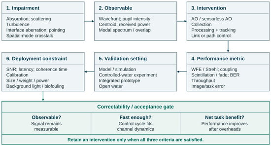
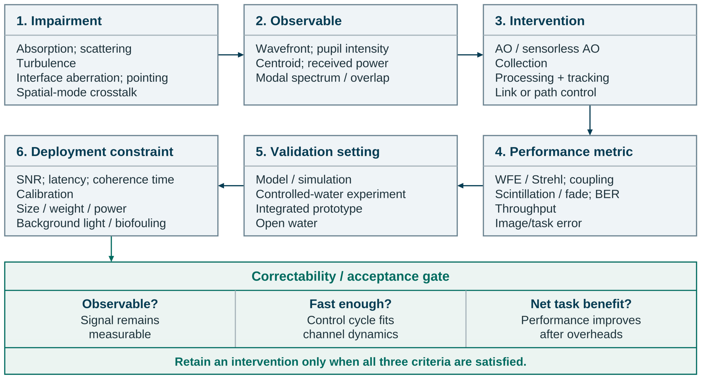
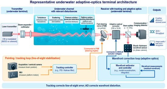
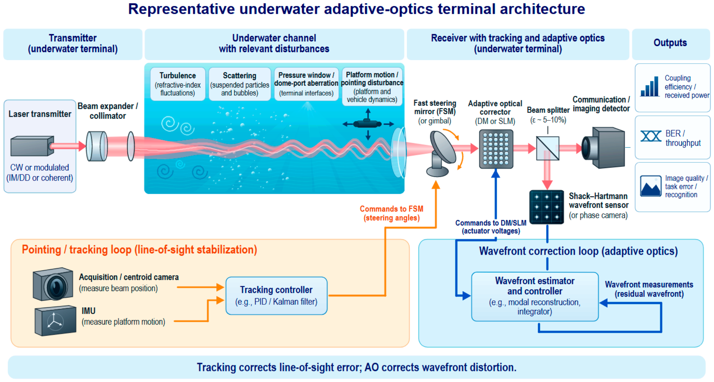
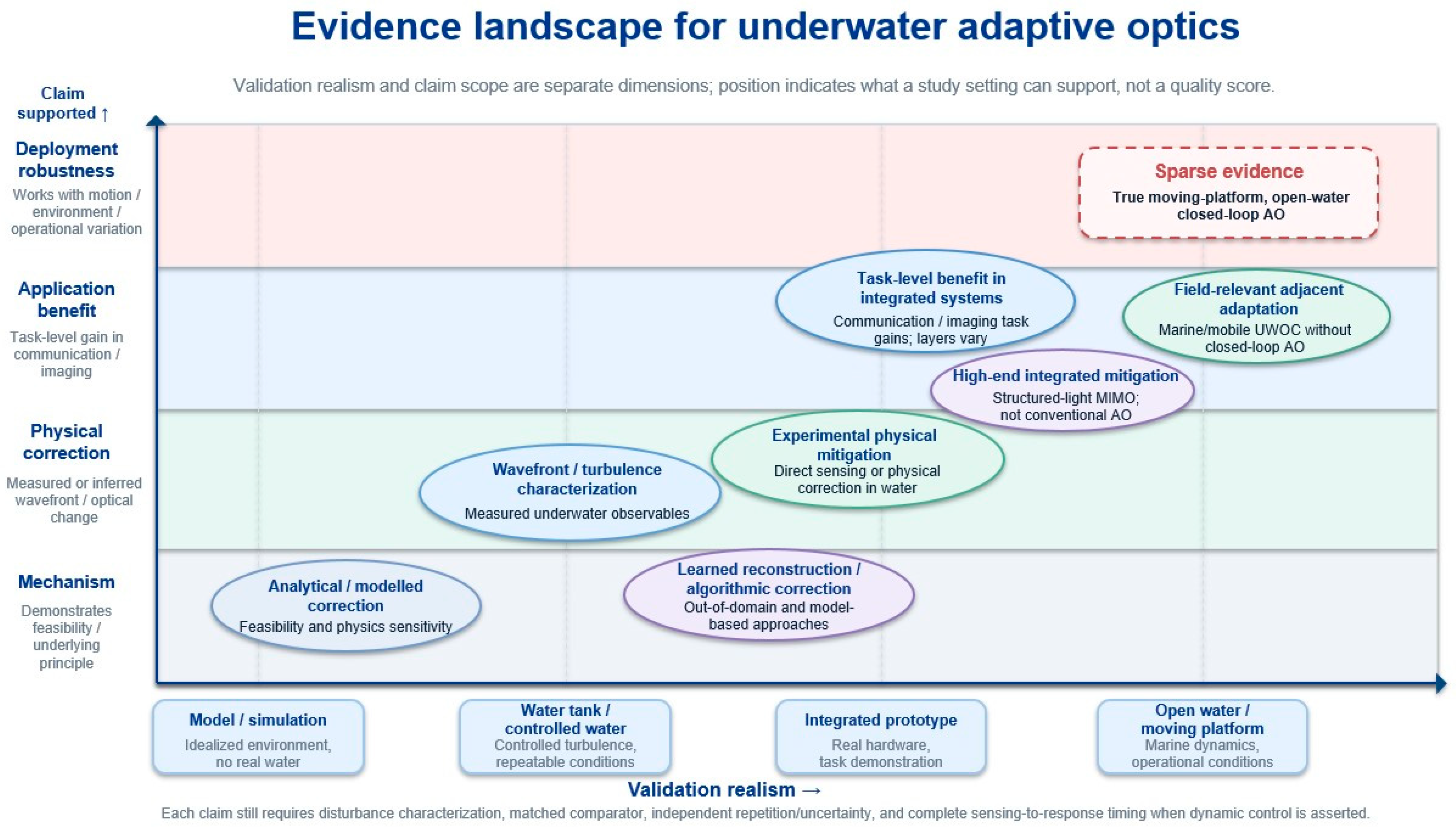

Disclaimer/Publisher’s Note: The statements, opinions and data contained in all publications are solely those of the individual author(s) and contributor(s) and not of MDPI and/or the editor(s). MDPI and/or the editor(s) disclaim responsibility for any injury to people or property resulting from any ideas, methods, instructions or products referred to in the content. |
© 2026 by the authors. Licensee MDPI, Basel, Switzerland. This article is an open access article distributed under the terms and conditions of the Creative Commons Attribution (CC BY) license.