


Abstract
China is rich in magnetite mineral resources, but they are generally characterized by low grade, fine dissemination size, and a high content of harmful impurities. Wet low-intensity magnetic separation (WLIMS) is an important method for processing fine-grained magnetite. However, during the separation process, fine magnetite particles are prone to magnetic agglomeration, which makes it difficult for conventional WLIMS separators to achieve high-selectivity separation. To address this issue, a novel WLIMS separator based on a rotating magnetic system was developed in this investigation, and its separation characteristics were systematically investigated through a combined approach comprising CFD–DEM–FEM multiphysics coupling simulations and experimental validation. Simulation results indicate that the rotating magnetic system significantly reduces the chain length and the structural stability of magnetic agglomerates just as magnetite particles enter the magnetic field region. Furthermore, under the rotating action of the magnetic system, the magnetic chains only enclose a portion of the intergrowth minerals, while gangue minerals remain unattached, which positively contributes to improved separation selectivity. Both laboratory-scale experimental results and industrial production data indicate that, compared to the conventional WLIMS separator, the rotating magnetic system WLIMS separator achieves significantly superior separation performance. For a magnetite ore with a grade of 57.68%, the rotating magnetic system WLIMS separator achieved an optimal concentrate grade of 65.43% (with a recovery of 94.78%), whereas the conventional WLIMS separator attained only 60.32% at a similar recovery rate. This investigation provides an important basis for the large-scale industrial application of rotating magnetic system WLIMS separators and the efficient development and utilization of fine-grained magnetite resources.
1. Introduction
The iron and steel industry constitutes a critical foundation of the national economy, with magnetite serving as a primary raw material for steelmaking owing to its advantageous resource endowment and relatively straightforward beneficiation and metallurgical processes. China is rich in magnetite mineral resources, but they are generally characterized by low grade, fine dissemination size, and a high content of harmful impurities. For the separation of such low-grade and fine-grained magnetite ores, wet drum low-intensity magnetic separation (WLIMS) is the most widely used technique in industrial practice [1]. However, conventional WLIMS separators still have limitations in directly producing high-grade concentrates from these magnetite ores. It is generally difficult to obtain a concentrate with a TFe grade exceeding 60%, and further upgrading using cleaning equipment such as magnetic separation columns is typically required. Taking the iron ore of Kunming Iron and Steel Group in Yunnan Province, China, as an example, after the raw ore is finely ground to 80% passing 0.074 mm, it undergoes a “rougher–cleaner” WLIMS process, producing an iron concentrate with a grade of approximately 58%, which must subsequently be upgraded to over 63% TFe using magnetic separation columns. However, magnetic column separation technology generally suffers from low throughput, high production costs, and significant maintenance challenges, making it difficult to meet the demands of large-scale industrial production [2]. Therefore, achieving economic, efficient, and high-selectivity separation of low-grade and fine-grained magnetite resources remains a critical challenge that urgently needs to be addressed in the field of mineral processing [3].
Difficulty in achieving high-grade concentrates when processing fine-grained magnetite using a WLIMS separator is largely attributed to the ease with which fine magnetite particles become magnetized within the magnetic field. This leads to dipole–dipole interactions between adjacent particles, resulting in the formation of chain-like, network-like, or even three-dimensional magnetic agglomerates aligned along the direction of background magnetic field lines [4]. During the separation process, these magnetic agglomerates mechanically entrain substantial amounts of gangue minerals, fine slimes, and poor intergrowths, severely compromising concentrate quality. Previous investigations have also indicated that the recovery of magnetite in a WLIMS separator is essentially a process of selective separation of magnetic chains and agglomerates [5]. Therefore, controlling the formation, stability, and breakage behavior of magnetic agglomerates has become one of the key scientific issues for improving the separation selectivity of WLIMS. Effectively mitigating gangue entrainment within magnetic agglomerates has become the central challenge in improving concentrate grade.
To reduce the extent of gangue entrainment in magnetic agglomerates, numerous researchers have recently conducted extensive investigations focusing on optimizing magnetic pole arrangements, introducing external loosening forces, and employing rotating magnetic systems [6,7]. For instance, some scholars have enhanced the magnetic flipping effect by reducing the pole spacing, increasing the number of magnetic poles, or adding auxiliary poles, thereby strengthening the disruption of magnetic agglomerates and improving separation precision [8,9,10]. In parallel, other studies have introduced auxiliary water flow into the separation chamber to improve the loosening of particle aggregates, thereby reducing mechanical entrainment [11]. Nevertheless, these approaches often exhibit limitations such as increased structural complexity, additional energy consumption, or insufficient enhancement of separation selectivity under industrial operating conditions. Additionally, some research findings indicate that the reverse driving effect generated by a rotating magnetic field can significantly enhance the tumbling frequency of magnetic agglomerates, facilitating the release of entrained gangue and thereby improving concentrate grade [12]. Compared to conventional methods, rotating magnetic field technology offers unique advantages because it can simultaneously promote magnetic aggregate dispersion and maintain high magnetite recovery without introducing excessive hydraulic disturbances.
Despite these promising results, the application of rotating magnetic field technology in WLIMS has received limited attention, and several fundamental issues remain unresolved. In particular, the particle-scale interaction mechanisms among magnetic force, fluid flow, and particle motion under rotating magnetic field conditions are still poorly understood. Moreover, the relationship between the dynamic evolution of magnetic agglomerates and the resulting separation performance has not yet been systematically established. These knowledge gaps hinder the rational design, optimization, and industrial implementation of rotating magnetic system WLIMS separators.
Based on the above background, we developed a novel WLIMS separator featuring counter-rotation between the magnetic system and the drum. To the best of our knowledge, systematic studies on the separation characteristics and high-selectivity separation mechanisms of this configuration have not yet been reported. Therefore, this study employs a CFD–DEM–FEM multiphysics coupling simulation method, combined with experimental validation, to systematically investigate the separation characteristics of the rotating magnetic system WLIMS separator for processing fine-grained magnetite. Special attention is paid to the dynamic evolution of magnetic agglomerates, gangue release behavior, and particle migration characteristics under rotating magnetic field conditions. The aim is to elucidate its separation mechanism, provide a foundation for its subsequent industrial application, and support the efficient development and utilization of fine-grained magnetite mineral resources.
2. Experimental
2.1. Rotating Magnetic System WLIMS Separator and Its Working Principle
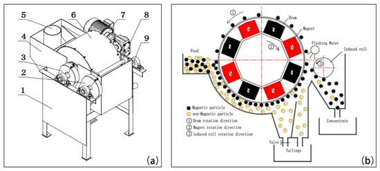
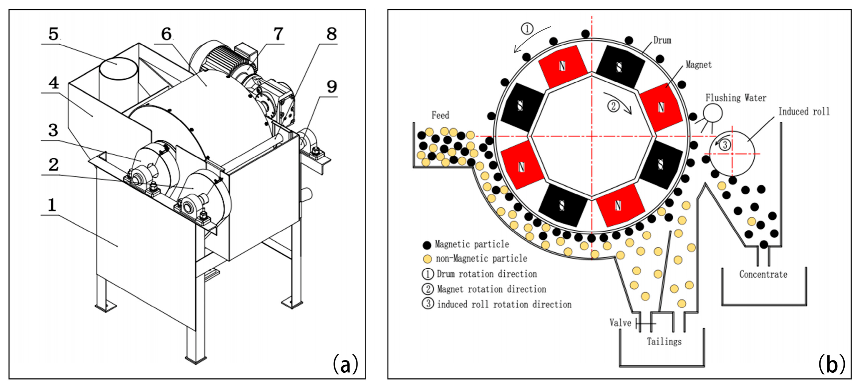
The main separator used in this investigation is the SXCT-0503 (BGRIMM Technology Group, Beijing, China) rotating magnetic system WLIMS separator. It consists of a frame, separation tank, separation drum, rotating magnetic system, and induction roll, as shown in Figure 1.
Figure 1.
Rotating magnetic system WLIMS separator (a) and its working principle (b). Notes: 1—Rack, 2—Discharge device drive system, 3—Magnetic drum drive system, 4—Separation tank, 5—Feed inlet, 6—Magnetic drum, 7—Magnetic system drive system, 8—Ore discharge water pipe, 9—Discharge device.
Upon startup, the magnetic system and the separation drum rotate in opposite directions. Slurry is then introduced into the separation tank via the feed pipe, whereupon magnetic minerals are attracted to the drum surface by magnetic force. Meanwhile, under the influence of a high-frequency alternating magnetic field, these magnetic minerals undergo vigorous tumbling both in the tank and on the drum surface, which effectively dislodges mechanically entrained gangue and other minerals. Subsequently, the attached magnetic minerals are carried by the drum into the unloading zone, where a high magnetic field generated by the induction roll attracts them from the drum onto the roll surface. From there, they rotate with the roll into the concentrate zone, while non-magnetic minerals and intergrowths flow with the slurry into the tailings box.
2.2. Material
A typical magnetite material from Dahongshan Group, China, was used for this separation investigation with a rotating magnetic system WLIMS separator. This material is a typical magnetite concentrate in China, and its grade is difficult to further improve due to its fine particle size.
The grade of Fe in the material is 57.68%, and the gangue minerals in the material are mainly augite, feldspar, and chlorite, as listed in Table 1. The material consists of 78.15% smaller than 0.074 mm and 58.63% smaller than 0.044 mm. Furthermore, it is noted that the iron (Fe) components in the material, as shown in Table 2, are basically distributed in the magnetite (Fe3O4) mineral.
Table 1.
Element analysis results of the material.
Table 2.
Iron-phase analysis of the material.
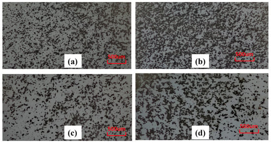
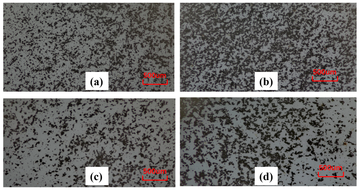
Given that the material is an iron concentrate obtained from low-intensity magnetic separation, the magnetite particles may retain residual magnetism, leading to agglomeration. Therefore, the agglomeration morphology was observed and analyzed using an optical microscope, and the results are shown in Figure 2. It can be seen that some particles are close to each other, forming a “micro-agglomerate” morphology. However, no obvious agglomerates are observed.
Figure 2.
Agglomeration morphology of the material. (a) −0.044 mm, 60%; (b) −0.044 mm, 75%; (c) −0.044 mm, 80%; (d) −0.044 mm, 95%.
3. Numerical Methodology
3.1. Mathematical Model
In the WLIMS process, the motion of particles is governed by the combined action of multiple force fields. In particular, when strongly magnetic particles are magnetized in a magnetic field, the inter-particle collision forces and magnetic dipole forces become more complex. To accurately describe the motion behavior of such particles, this study further incorporates the inter-particle interaction forces into the classical particle motion model [13]. Accordingly, the motion of particles can be solved based on Newton’s second law:
where is the mass of particle ; is the translational velocity of particle ; is the normal contact force between particle and other particles; is the tangential contact force between particle and other particles; is the interaction force between particle and the fluid; is the magnetic force acting on particle ; is the gravitational force acting on particle ; and is the magnetic dipole force between particles.
3.1.1. Contact Force Between Particles
In this work, particle contact interactions are modeled using the classical Hertz–Mindlin (no-slip) contact theory. When two particles come into contact, the contact force can be decomposed into a normal contact component and a tangential component .
The normal contact force consists of an elastic component derived from Hertzian contact theory and a damping component .
The elastic component can be calculated as follows:
where and are the Young’s moduli of particles i and j (), respectively; and are the Poisson’ s ratios of particles i and j, respectively; and are the radii of particle i and j (), respectively; and is the normal overlap between particles.
And the damping component can be calculated as follows:
where is the normal component of the relative velocity between particles (); and are the masses of particle i and j (), respectively; and is the restitution coefficient.
Moreover, the tangential force includes an elastic component and a damping component , calculated based on the Mindlin–Deresiewicz theory.
The elastic component can be calculated as follows:
where is the tangential overlap between particles (); and and are the shear moduli of particles i and j (), respectively.
And the damping component can be calculated as follows:
where is the tangential component of the relative velocity between particles (); and are the masses of particles i and j (), respectively; and is the restitution coefficient.
The tangential force is limited by the static friction force . When the tangential force exceeds, a torque is applied at the contact surface to account for rolling friction, as described by the following equation:
where is the rolling friction coefficient; and is the distance from the contact point to the center of mass .
3.1.2. Magnetic Dipole–Dipole Interaction Forces ()
The magnetic dipole force is the dominant interaction responsible for the magnetic agglomeration of strongly magnetic particles, and the interaction force between magnetic dipoles can be expressed as follows [14]:
where is the distance between particles (); is the unit vector pointing from particle j to particle i; mi, mj are the magnitudes of the magnetic moments of particle i and particle j, respectively; and are the unit magnetic moment vectors of particles i and particles j, respectively.
The magnetic moment is obtained from:
where is the magnetization of the particle i.
It should be noted that in practical simulations, the direction of the magnetic field within the separation zone varies with spatial position, and consequently, the direction of the magnetic dipole force exerted on the particles changes accordingly. Particularly when the magnetic system rotates, the magnetic field inside the separation zone undergoes intense periodic alternating variations, which in turn causes the magnetic dipole force to exhibit rapid periodic fluctuations. This mechanism facilitates the loosening of magnetic agglomerates.
3.1.3. Magnetic Attraction Force
The magnetic force acting on a particle is calculated as follows [15,16]:
where is the vacuum permeability (; is the magnetic susceptibility of particle ; is the volume of particle ; and is the magnetic field intensity ().
It should be noted that the magnetic field within the separation zone alternates as the magnetic system rotates; therefore, the magnetic field intensity is treated as a time-varying value in the EDEM simulation.
3.1.4. Gravitational Force and Buoyancy
The gravitational force acting on particle is given by:
where and are the radius and density of particle , respectively; and is the gravitational acceleration.
And the buoyant force exerted by the fluid is given by:
where is the fluid density.
3.1.5. Drag Force
The drag force is determined based on the relative velocity between the particle and the surrounding fluid. The particle Reynolds number is defined as follows:
where is the diameter of particle i (m); is the fluid density (); is the fluid viscosity (); and and are the velocity vectors of particle i and the fluid (), respectively.
Depending on the particle Reynolds number, the drag coefficient is calculated using Stokes’ law for , the Schiller–Naumann correlation for , and a constant value for [17].
The drag force is then calculated as follows:
where is the particle cross-sectional area.
3.2. Model Construction and Parameter Settings
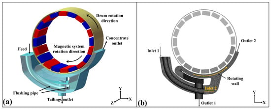
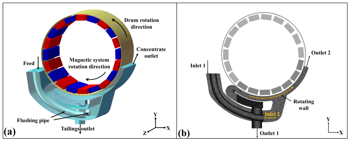
A three-dimensional model of the wet low-intensity magnetic separator (WLIMS) was established in SolidWorks 2022, as illustrated in (Figure 3a). The drum has an outer diameter of 502 mm, an inner diameter of 496 mm, and an axial length of 600 mm. The principal geometric dimensions used in the numerical model are summarized in Table 3.
Figure 3.
Three-dimensional geometric model (a); Side view of the meshing result (b).
Table 3.
Geometric model parameters.
To ensure adequate spatial resolution while maintaining computational efficiency, the fluid domain within the separation chamber was discretized using the Meshing module with a global element size of 2.5 mm. The resulting computational grid consisted of 6,240,747 cells with an average mesh quality of 0.84781 (Figure 3b), which satisfies the accuracy requirements for the subsequent CFD–DEM simulations.
3.2.1. Fluent Parameter Settings
The hydrodynamic behavior inside the separator was calculated using ANSYS Fluent 2022R1. The slurry feed inlet and wash-water inlet were both specified as velocity-inlet boundaries, whereas the tailings discharge was represented by a velocity-outlet boundary with a prescribed negative velocity. The concentrate outlet was treated as a pressure outlet exposed to atmospheric pressure, and the backflow volume fraction of air was set to 100% to reproduce the free-surface condition.
The drum surface was defined as a rotating wall under an absolute reference frame. Prior to the transient calculation, the separation chamber was initialized with a water volume fraction of 100%, ensuring that the entire domain was completely filled with water. The operating conditions considered in this work are listed in Table 4.
Table 4.
Parameters in Fluent.
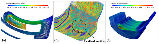
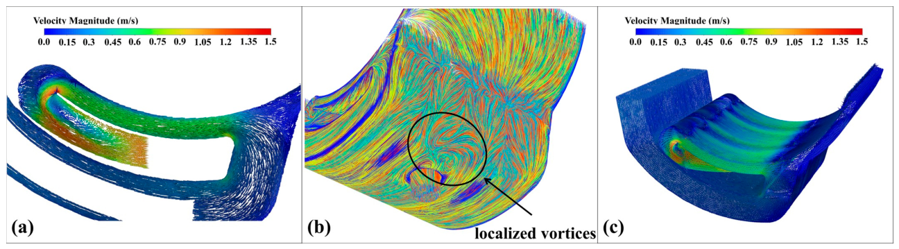
The calculated flow field provides the hydraulic conditions governing particle transport inside the separator. In the present study, both the feed slurry and wash-water velocities were fixed at 0.2 m/s. As shown in (Figure 4a), the fluid velocity remains relatively low in the inlet region and gradually accelerates toward the wash-water outlet. The combined influence of the symmetrically arranged wash-water pipes and the obstruction caused by the tailings outlet generates several recirculation zones near the bottom of the separation chamber (Figure 4b), resulting in an uneven axial velocity distribution (Figure 4c).
Figure 4.
Flow field distributions of the WLIMS separator: (a) Front view, (b) zoom-in view of localized vortices, (c) overall view.
Within the magnetic capture region, the velocity close to the drum surface is lower than that in the lower part of the chamber because the rotating drum induces a boundary layer that alters the local flow characteristics. These flow features directly influence particle trajectories and magnetic capture efficiency.
3.2.2. EDEM Parameter Settings
Particle motion was simulated using EDEM 2022. Three representative particle types, namely magnetite, quartz, and intergrowth particles, were included in the numerical model, each accounting for one-third of the total particle population.
To represent different liberation degrees, the intergrowth particles were further classified into three magnetic susceptibility levels corresponding to Fe mass fractions of 50%, 40%, and 30%, respectively. Each category occupied an equal proportion of the intergrowth particles, equivalent to 11.1% of the total particles [18]. The material properties and operating parameters adopted in the DEM simulations are summarized in Table 5.
Table 5.
Parameters in EDEM.
3.2.3. MAXWELL Parameter Settings
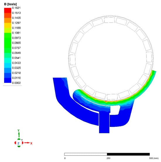
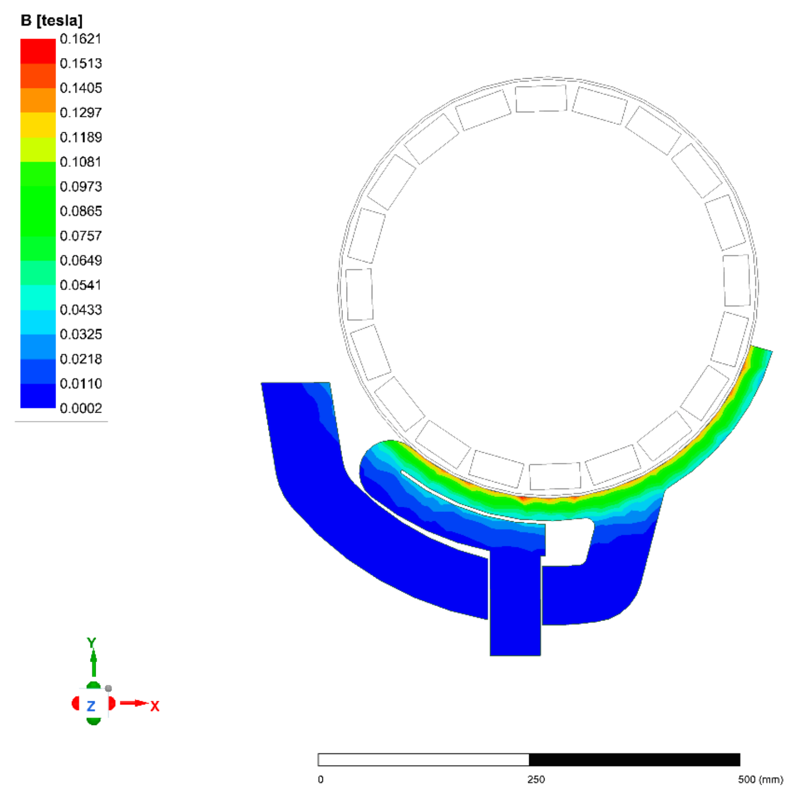
The magnetic field distribution was established in ANSYS Maxwell 2022 Permanent magnets were arranged circumferentially around the drum following an alternating N–S polarity configuration to generate the low-intensity magnetic field required for particle separation. The calculated magnetic flux density distribution is presented in (Figure 5).
Figure 5.
Magnetic field distributions in separating zone of the WLIMS separator.
To reduce computational cost, only the static magnetic field within the separation zone was solved in Maxwell. The dynamic effect introduced by magnetic system rotation was reproduced through an external API, which continuously updated the magnetic field according to the instantaneous angular position of the magnetic system during the coupled CFD–DEM calculation. This strategy significantly improved computational efficiency while preserving the temporal variation of the magnetic field experienced by moving particles.
As illustrated in Figure 5, the magnetic flux density on the drum surface reaches a maximum value of approximately 0.15 T. Owing to the alternating polarity of adjacent permanent magnets, both the magnitude and direction of the magnetic field vary periodically along the drum circumference. Consequently, the surface magnetic flux density fluctuates within a range of approximately 0.10–0.15 T, producing strong magnetic field gradients that enhance the magnetic attraction and rolling behavior of magnetic particles on the drum surface.
4. Results and Discussion
4.1. Simulation
4.1.1. Motion Characteristics of Magnetite Particles
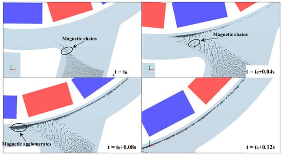
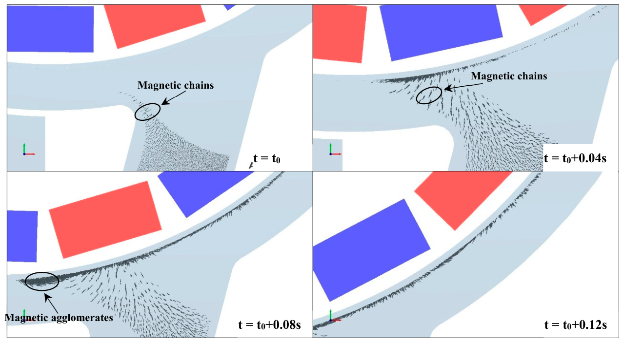
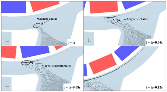
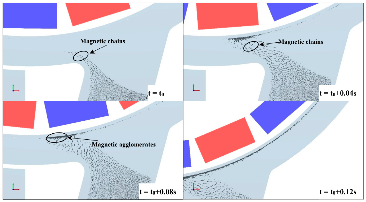
To systematically investigate the effects of magnetic system rotation speed on the motion characteristics of strongly magnetic mineral particles, as well as on the formation process and morphological characteristics of magnetic chains, simulations were conducted to analyze the dynamic motion characteristics of pure magnetite particles under magnetic system rotation speeds of 0 r/min, 100 r/min, and 200 r/min, as shown in Figure 6, Figure 7 and Figure 8. The simulation results show that the magnetite particles quickly form chain-like structures upon entering the magnetic field region and move toward the drum surface in the form of magnetic chains. After reaching the drum surface, these chains further accumulate to form magnetic agglomerates. When the magnetic system is stationary, the magnetite particles form much longer magnetic chains, and the accumulation thickness on the drum surface is also greater, as shown in Figure 4. This indicates that these magnetic chains or agglomerates are relatively stable in structure and are not easily disrupted.
Figure 6.
Motion characteristics of magnetite particles in a stationary magnetic system.
Figure 7.
Motion characteristics of magnetite particles at a magnetic system rotation speed of 100 r/min.
Figure 8.
Motion characteristics of magnetite particles at a magnetic system rotation speed of 200 r/min.
As shown in Figure 7 and Figure 8, when the magnetic system rotates, both the length of magnetic chains and the accumulation thickness on the drum surface decrease significantly. Furthermore, as the rotation speed increases from 100 r/min to 200 r/min, the length and thickness are further reduced. This can be attributed to the fact that the rotating magnetic system intensifies the tumbling motion of particles, which loosens the particle population and disrupts the magnetic chain structure from within, thereby reducing chain stability. More importantly, the rotating magnetic system significantly shortens the magnetic chains that form immediately upon magnetite particles entering the magnetic field region, which plays a positive role in suppressing particle agglomeration.
4.1.2. Magnetic Agglomeration Characteristics of Mixed Mineral Particles
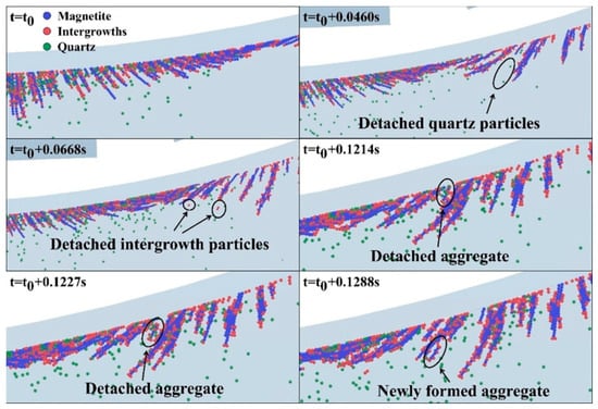
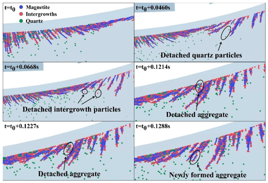
To systematically investigate the effect of magnetic system rotation on separation performance and the magnetic agglomeration behavior of particles, the motion characteristics and magnetic agglomeration behavior of magnetite particles, gangue particles, and intergrowth particles under both stationary and rotating magnetic system conditions were simulated, as shown in Figure 9 and Figure 10. The simulation results show that when the magnetic system is stationary, particles rapidly form magnetic chains upon entering the magnetic field region, encapsulating a large amount of intergrowth and gangue minerals. These chains, carrying substantial amounts of gangue and intergrowths, are then captured onto the surface of the separation drum. On the drum surface, as the drum rotates and particles move, some gangue minerals are released from the magnetic chains, whereas intergrowth minerals are more difficult to dislodge. In this case, the magnetic agglomerates captured on the drum surface still encapsulate substantial amounts of gangue and intergrowth minerals, resulting in a low concentrate grade.
Figure 9.
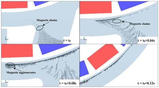
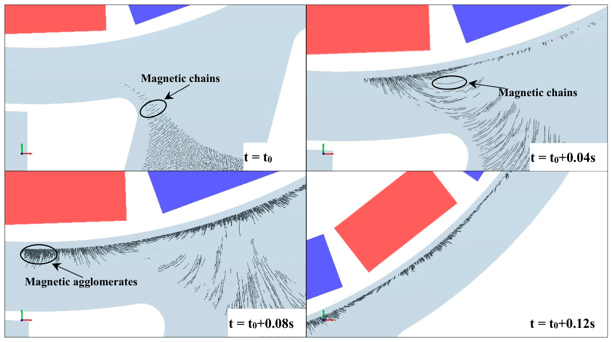
Magnetic agglomeration characteristics of particles without rotation of the magnetic system.
Figure 10.
Magnetic agglomeration characteristics of particles at a magnetic system rotational speed of 100 r/min.
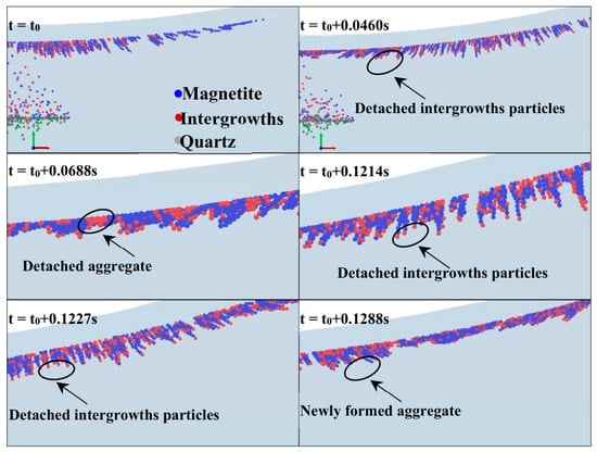
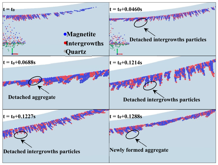
When the magnetic system rotates, particles form magnetic chains upon entering the magnetic field region. However, these chains are shorter in length and exhibit lower structural stability. Under such conditions, the magnetic chains encapsulate fewer intergrowth minerals and do not entrain gangue minerals, as shown Figure 7. Consequently, when these chains carrying only a limited number of intergrowths are captured by the separation drum, the grade of concentrate is significantly improved. These findings indicate that the rotating magnetic system plays a positive role in enhancing separation efficiency and concentrate grade.
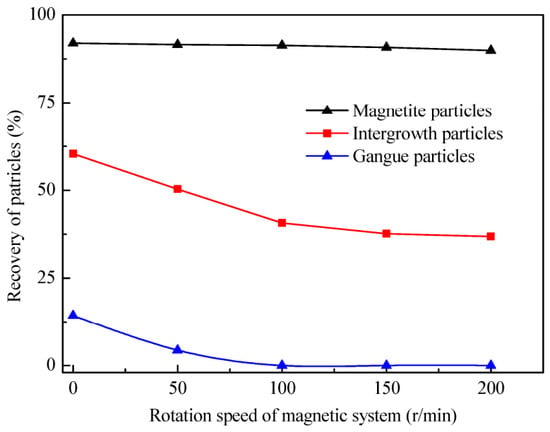
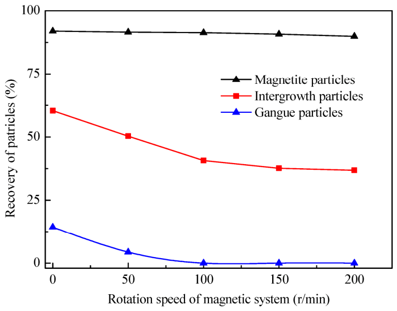
To further investigate the effect of magnetic system rotation on separation performance, we analyzed the simulation processes under different conditions, statistically examining the capture amounts of magnetite particles, locked particles, and gangue mineral particles at various rotation speeds, as shown in Figure 11. As shown, the recovery of intergrowth particles markedly decreases with an increase in the rotation speed from 0 r/min to 100 r/min, whereas the recovery of magnetite particles exhibits no significant change. Additionally, the recovery of gangue mineral particles significantly decreases from 14.35% to 4.37% and then sharply decreases to 0 with a further increase in the rotation speed to 100 r/min. These findings indicate that the rotating magnetic system significantly reduces the mechanical entrainment of locked particles and gangue mineral particles, which is highly beneficial for improving concentrate grade.
Figure 11.
Effect of magnetic system on recovery for particles.
4.2. Laboratory-Scale Experimental Study
To further validate the superiority of the rotating magnetic system WLIMS separator for the high-selectivity separation of fine-grained magnetite, separation tests were conducted under laboratory conditions using the SXTC-350 separator (BGRIMM Technology Group, Beijing, China).
4.2.1. Effect of Grinding Fineness
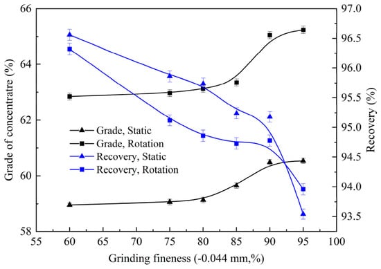
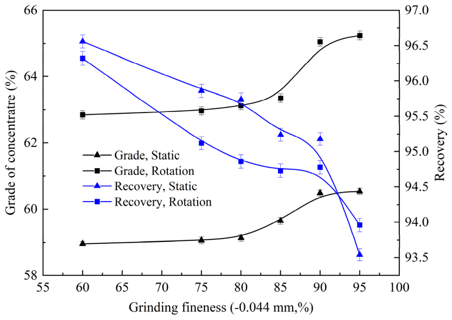
Given that grinding fineness is a key factor determining the degree of mineral liberation, it significantly affects concentrate grade. Therefore, in this investigation, the effect of grinding fineness on separation performance was systematically investigated under both stationary and rotating magnetic system conditions (with the rotating magnetic system operating at 100 r/min), as shown in Figure 12. The experimental results indicate that the grade of concentrate significantly improves with an increase in the material fineness from 60% to 90% below 0.044 mm, and then it tends to level off with a further increase in fineness to 95% below 0.074 mm. Meanwhile, the iron recovery in the concentrate decreases with an increase in the grinding fineness of material. Compared to the stationary magnetic system, the rotating magnetic system achieves a significantly higher concentrate grade at a similar recovery level. For instance, at a grinding fineness of 90% below 0.044 mm, the grade of concentrate obtained in the rotating magnetic system is 65.15%, whereas that in the stationary magnetic system is only 60.48%.
Figure 12.
Effect of grinding fineness on separation performance.
An increase in grinding fineness enhances the degree of mineral liberation, thereby reducing the content of intergrowth particles. And the simulation results indicate that in the rotating magnetic system, the magnetic agglomerates formed by particles encapsulate only intergrowth particles. Therefore, as the grinding fineness increases, the rotating magnetic system significantly improves the separation efficiency and concentrate grade. Furthermore, the experimental results also demonstrate that, under the conditions of ensuring sufficient mineral liberation, the rotating magnetic system plays a significant role in improving concentrate grade.
4.2.2. Effect of Magnetic System Rotation Speed
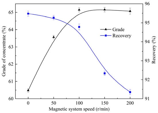
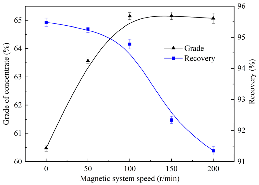
For the rotating magnetic system WLIMS separator, the rotation speed of the magnetic system is a key factor affecting separation performance, with the results shown in Figure 13. It can be observed that when the magnetic system transitions from a stationary to a rotating state, the concentrate grade increases significantly. The experimental results indicate that the grade of concentrate is significantly improved from 60.48% to 65.16% with an increase in the rotation speed from 0 r/min to 100 r/min, and then it tends to level off with a further increase in the rotation speed to 200 r/min. Meanwhile, the iron recovery of the concentrate decreases with an increase in the rotation speed.
Figure 13.
Effect of magnetic system rotation speed on separation performance.
The rotating magnetic system causes an alternating change in the magnetic field within the separation zone, which in turn leads to alternating variations in both the magnetization direction of the particles and the direction of magnetic force acting on the particles, thereby intensifying the tumbling motion of the particles. This enhanced tumbling motion disrupts the magnetic chain structure from within, reducing its stability and facilitating the release of intergrowth and gangue minerals encapsulated in the chains. Therefore, appropriately increasing the rotation speed of the magnetic system can effectively improve concentrate grade. However, when the rotation speed is excessively high, the particles undergo violent tumbling and slide on the surface of the separation drum, which causes some fine magnetite particles to detach from the drum surface, leading to a decrease in recovery.
4.2.3. Effect of Magnetic Induction
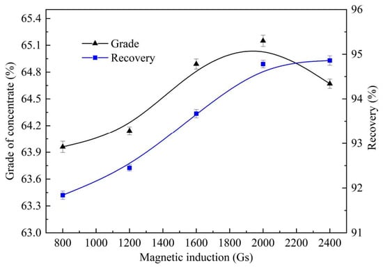
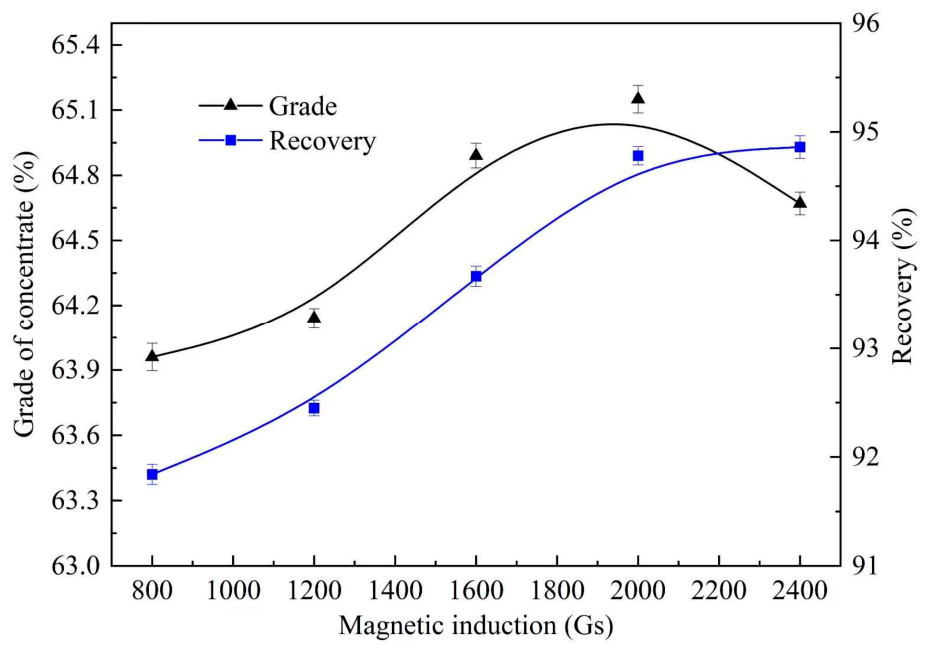
Magnetic induction is a key factor determining the magnetic force acting on particles and thus has a significant effect on separation performance, as shown in Figure 14. It can be observed that the concentrate grade rises from 63.96% to 65.15% with an increase in the magnetic induction from 800 Gs to 2000 Gs. Meanwhile, the iron recovery of concentrate increases with an increase in magnetic induction.
Figure 14.
Effect of magnetic induction rotation speed on separation performance.
An increase in magnetic induction significantly enhances the magnetic force acting on particles. Under such conditions, some well-liberated fine magnetite particles are more easily captured by the drum surface, which contributes to both an increase in recovery and an improvement in concentrate grade. However, excessive magnetic induction tends to intensify the encapsulation and entrainment of gangue minerals within magnetic agglomerates, thereby adversely affecting concentrate grade.
4.3. Industrial Test Results
The simulation and small-scale experimental results confirm that the rotating magnetic system plays an important role in improving the separation efficiency of the WLIMS separator. In this study, the separation performance of an industrial-scale rotating magnetic system WLIMS separator (with the rotating magnetic system operating at 100 r/min) was compared to that of a conventional WLIMS separator under actual production conditions, as shown in Table 6.
Table 6.
Comparison of production performance between rotating magnetic system WLIMS separator and conventional WLIMS separator.
The comparison results indicate that for a rougher concentrate with a feed grade of 57.68%, a single pass through the rotating magnetic system WLIMS separator yields an iron concentrate with an iron grade of 65.43% and a recovery of 95.68%, whereas the conventional WLIMS separator achieves an iron grade of only 60.32% with a similar recovery. These results demonstrate that the rotating magnetic system achieves significantly better separation performance in practical applications. Multi-element and iron-phase analyses were conducted on the final concentrate product, and the results are presented in Table 7 and Table 8, respectively. These results indicate that the quality of the iron concentrate is significantly improved after separation by the rotating magnetic system magnetic separator.
Table 7.
Element analysis results of concentrate product.
Table 8.
Iron-phase analysis concentrate product.
5. Conclusions
- During WLIMS, strongly magnetic magnetite particles form chain-like magnetic structures upon entering the magnetic field region, encapsulating substantial amounts of gangue and intergrowth minerals. When the magnetic system rotates, the chain length is significantly shortened, and the structural stability is reduced immediately as the magnetite particles enter the magnetic field region. Simulation results further indicate that in a rotating magnetic system, the magnetic chains formed by the magnetite particles encapsulate only a portion of the intergrowth minerals, with no gangue entrainment. This is beneficial for improving separation efficiency and concentrate grade.
- For a magnetite ore with a grade of 57.68%, under optimal process conditions, the rotating magnetic system WLIMS separator achieved a concentrate with a recovery of 95.68% and a grade of 65.43%, whereas a conventional WLIMS separator could only upgrade the iron grade to 60.32% with a similar recovery. This indicates that, compared to the conventional WLIMS separator, the rotating magnetic system WLIMS separator can achieve a significantly higher concentrate grade. In addition, process parameters such as grinding fineness, magnetic induction intensity, and rotation speed of the magnetic rotating system significantly influence the separation performance. Moreover, industrial production data further confirm that the rotating magnetic system wet low-intensity magnetic separator can achieve significantly superior separation performance compared to its conventional counterpart.
Author Contributions
H.S.: Writing—original draft, Methodology, Software. B.W.: Writing—original draft, Methodology, Software. H.Z.: Methodology, Software. J.Z.: Writing—review & editing, Conceptualization, Funding acquisition, Supervision, Methodology. Z.S.: Supervision, Methodology. All authors have read and agreed to the published version of the manuscript.
Funding
We sincerely acknowledge the funding for this research provided by the National Natural Science Foundation of China (Grant No. 52564036), the Open Foundation of State Key Laboratory of Mineral Processing (Grant No. BGRIMM-KJSKL-2026-30), Yunnan Fundamental Research Projects (Grant No. 202401AT070371), and the Yunnan Province High-level Talent Introduction Program Project (Grant No. XDYC-QNRC-2022-0125).
Data Availability Statement
Data is contained within the article.
Conflicts of Interest
The authors declare that they have no known competing financial interests or personal relationships that could have appeared to influence the work reported in this paper.
References
- Wang, F.W.; Tang, D.D.; Dai, H.X.; Zhang, S.T.; Gao, L.K.; Gong, M.H. Design optimization and manufacturing of an innovative precise low-intensity magnetic separator based on a multiphysics model. Miner. Eng. 2021, 171, 107118. [Google Scholar] [CrossRef] [Scilit]
- Zhang, M.; Guo, X.; Ren, W.; Cui, S.; Dai, S. Research Status and Optimization Improvement of Magnetite Column Separator. MetalMine 2020, 191–196. (In Chinese) [Google Scholar] [CrossRef]
- Yi, F.; Chen, L.; Liu, X.; Zeng, J.; Xue, Z. Development of a centrifugal dry magnetic separator for separation of fine magnetite ore. Powder Technol. 2024, 437, 119557. [Google Scholar] [CrossRef] [Scilit]
- Ostapenko, S.P.; Opalev, A.S. Methodical Approach to Studies of Magnetic Interaction of Fine Particles in an Aqueous Suspension Using Computer Simulation. Theor. Found. Chem. Eng. 2024, 58, 1293–1299. [Google Scholar] [CrossRef] [Scilit]
- Rayner, J.G.; Napier-Munn, T.J. The mechanism of magnetics capture in the wet drum magnetic separator. Miner. Eng. 2000, 13, 277–285. [Google Scholar] [CrossRef] [Scilit]
- Dworzanowski, M. Optimizing the performance of wet drum magnetic separators. J. S. Afr. Inst. Min. Metall. 2010, 110, 643–653. [Google Scholar]
- Wu, L.W.; Tang, D.D.; Wen, J.L.; Gong, M.H.; Wang, F.W.; Dai, H.X. Advancements and applications of numerical simulation in enhancing the efficiency of low-intensity magnetic separators. Miner. Eng. 2025, 234, 109750. [Google Scholar] [CrossRef] [Scilit]
- Mohanraj, G.T.; Rahman, M.R.; Joladarashi, S.; Hanumanthappa, H.; Shanmugam, B.K.; Vardhan, H.; Rabbani, S.A. Design and fabrication of optimized magnetic roller for permanent roll magnetic separator (PRMS): Finite element method magnetics (FEMM) approach. Adv. Powder Technol. 2021, 32, 546–564. [Google Scholar] [CrossRef] [Scilit]
- Yuan, Z.T.; Zhao, X.; Meng, Q.Y.; Xu, Y.K.; Li, L.X. Effect of selective coating of magnetite on improving magnetic separation of ilmenite from titanaugite. Miner. Eng. 2020, 149, 106267. [Google Scholar] [CrossRef] [Scilit]
- Tian, X.; Wu, L.; Zhao, Z.; Dai, H.; Qi, L.; Wang, F. Modeling of separation performance prediction model for industrial low intensity magnetic separation equipment. Miner. Eng. 2025, 228, 109311. [Google Scholar] [CrossRef] [Scilit]
- Chen, B. Development and application of wet drum magnetic separator bottom box with cleaning zone. Gansu-Metallurgy 2006, 39–40. (In Chinese) [Google Scholar] [CrossRef]
- Ku, J.; Chen, H.; He, K.; Yan, Q. Simulation and observation of magnetic mineral particles aggregating into chains in a uniform magnetic field. Miner. Eng. 2015, 79, 10–16. [Google Scholar] [CrossRef] [Scilit]
- Kumar, R.; Sarkar, S. Erosion analysis of radial flow hydraulic turbine components through FLUENT-EDEM coupling. Powder Technol. 2023, 428, 118800. [Google Scholar] [CrossRef] [Scilit]
- Liu, T.; Gong, X. Simulation of magneto-induced rearrangeable microstructures of magnetorheological plastomers. Soft Matter 2013, 42, 10069–10080. [Google Scholar] [CrossRef] [Scilit]
- Lindner, J. Simulation of magnetic suspensions for HGMS using CFD, FEM and DEM modeling. Comput. Chem. Eng. 2025, 54, 111–121. [Google Scholar]
- Luo, L.; Nguyen, A.V. A review of principles and applications of magnetic flocculation to separate ultrafine magnetic particles. Sep. Purif. Technol. 2017, 172, 85–99. [Google Scholar] [CrossRef] [Scilit]
- Schlichting, H.; Gersten, K. Boundary-Layer Theory; Springer: Berlin/Heidelberg, Germany, 2016. [Google Scholar]
- Zhang, H.T.; Zeng, J.W.; Chen, L.Z. Numerical simulation study on magnetic agglomeration behavior in wet low-intensity magnetic separation. Powder Technol. 2025, 470, 122003. [Google Scholar] [CrossRef] [Scilit]

Disclaimer/Publisher’s Note: The statements, opinions and data contained in all publications are solely those of the individual author(s) and contributor(s) and not of MDPI and/or the editor(s). MDPI and/or the editor(s) disclaim responsibility for any injury to people or property resulting from any ideas, methods, instructions or products referred to in the content. |
© 2026 by the authors. Licensee MDPI, Basel, Switzerland. This article is an open access article distributed under the terms and conditions of the Creative Commons Attribution (CC BY) license.