


Abstract
Research on the surrounding rock stability and its control during gob-side entry driving with a narrow pillar (GSED-NP) is of critical importance for ensuring safe mining operations and efficient production in underground coal mines. This work proposed a thick anchored dual-layer locking (TADL) supporting technology by analyzing the big and small voussoir beam (BSVB) weighting characteristics in GSED-NP as well as engineering implementation and on-site validation. First, field surveys and numerical simulation show that the 9.60 m and 10.65 m thick medium grained sandstone in the overlying strata were fractured in the coal body of the next face, and formed BSVB structure after rotation, subsidence, and re-hinging. Under the effect of stress transfer of BSVB structure, the lateral abutment pressure distribution is characterized by internal and external stress field (IESF) distribution. Second, numerical calculation was carried out according to the above characteristics. Third, a supporting technical scheme was formulated and implemented, and the field monitoring data proved the ideal outcome. Finally, the influence of the critical fracture location of the main roof on the stress distribution was discussed, and it is thought that the stress distribution is mainly related to the main roof fracture location which has a critical range on the stress transfer. This research can provide a reference for the surrounding roadway control under similar conditions.
1. Introduction
Gob-side entry driving with narrow pillar (GSED-NP) is a commonly adopted roadway layout technique, where the roadway is driven along the goaf boundary [1,2,3]. In field engineering practice, roadway in such conditions is not only influenced by the long-term, gradual pressurization induced by abutment pressures—which originate from the transfer of overlying strata loading supports toward the deep coal wall—but it is also directly affected by the severe dynamic load caused by the strata movement [4,5,6,7]. This leads to the large deformation of GSED-NP [8,9,10]. Therefore, how to maintain the stability of the GSED-NP is a key issue for safe and efficient mining [11].
Currently, many scholars have carried out numerous studies with respect to surrounding rock control technology of GSED-NP. Previous studies both at home and abroad mainly focus on the stress redistribution caused by mining, and the influence of the formation of overlying strata structure on the load of gob-side roadway. When natural conditions such as burial depth and roof occurrence are determined, the distribution of lateral stress in the goaf and its peak position are mainly related to the overburden structure formed by the rotation and subsidence after the roof fracture in the goaf [12,13]. Therefore, many studies about overburden structure have been conducted. The spatial structure of the overlying strata in longwall stopes has been profoundly discussed [14], establishing a theoretical foundation for predicting dynamic strata behaviors such as rock bursts [15]. Building on this, recent studies have further revealed the disaster-causing mechanisms of overlying strata structures in complex geological settings—such as close-distance coal seam groups [16]—and demonstrated that modifying the lateral overlying roof structures can serve as an effective mechanism for rock burst prevention on the gob-side [17]. For example, Qian et al. [18] and Zhu et al. [19,20] believe that after the lateral roof is broken, it will form a voussoir beam with the adjacent rock blocks under the action of horizontal compression force. Huang et al. [21] and Liu et al. [22] studied the influence laws of the roof fracture position on the surrounding rock stress, and established a theoretical formula for the optimal roof cutting position for gob-side entry. Hou and Li [23], Li et al. [12] and Zhu et al. [24] studied the influencing factors of the lateral main roof fracture location, and believed that the fracture location of the main roof in the coal body of next face mainly depended on the thickness of the top coal and the immediate roof, and the rock mechanical properties of the top coal, the immediate roof, and the main roof, as well as the thickness of the main roof and the load-bearing layer above it. They thought that the big structure formed by the hinge of voussoir beam would significantly impact the surrounding rock stability of the small structure composed of roadways and coal pillars. The key rock is an important part of the big structure, and its fracture location and rotation subsidence are key factors determining the stability of the surrounding rock.
Furthermore, the lateral abutment pressure area can be divided into the relaxation zone, the abutment pressure zone with highly concentrated stress, and the in situ stress zone [25,26]. This law provides basic guidance for the selection of pillar width. On the one hand, if the roadway is excavated along a large coal pillar, it will undergo strong creep deformation because it is under lateral peak stress, which will make the maintenance of the roadway difficult. On the other hand, if the pillar width is too small, the roadway section will shrink too much during working face extraction [27,28,29,30,31]. Therefore, the selection of the pillar width determined the stress redistribution law. Based on this idea, Poulsen [32] carried out theoretical research and proposed a coal pillar load calculation method to evaluate the coal pillar stability. Wang and Cai [33] proposed a time-varying model for brittle coal pillars. Wu et al. [34,35] studied the development mode of shear and tension fractures of coal pillars. Jiang et al. [36,37] studied the role of pillar width optimization in reducing roadway stress. In fact, the reasonable selection of the pillar width will determine whether the roadway is in a low stress zone, and the bearing performance. For this reason, the position of pillar width shall be adjusted rationally on the basis of the roof structure.
In terms of reinforcing support structures, the bolt and cable support technique is currently the primary approach employed to control roadway surrounding rock deformation induced by intensive mining activities. Nevertheless, under deep mining scenarios, the anchored surrounding rock in gob-side entries still tends to undergo failure and instability, which is triggered by intricate mechanisms of energy accumulation and release [38]. To tackle these severe deformation issues, numerous researchers have developed bolt-cable supporting systems tailored for intensive mining conditions in recent years by modifying the structure of bolts and cables. For instance, He et al. [39,40] and Wang et al. [41] proposed a constant-resistance and large-deformation cable that is applicable to gob-side entry driving with no-pillar mining. Once this anchor cable reaches its designed resistance, it maintains a constant resistance level as the deformation increases, this mechanism alleviates energy concentration. Additionally, Yuan et al. [4] and Xie et al. [42] proposed a new type of cable bolt, which overcomes the spatial constraints associated with traditional bolts. Furthermore, Wang et al. [8,43,44] installed cables in deep stable rock formations, enabling the mobilization of a broader range of rock masses to resist deformation and fully utilizing the self-bearing capacity. Collectively, these studies emphasize that the core objective of bolt and cable is to maximize the load-bearing potential of the rock mass itself.
As mentioned above, many studies have investigated the pressure mechanism of GSED-NP. However, the structural characteristics of lateral voussoir beam and its weighting mechanism in GSED-NP have received relatively little research attention. Moreover, building on our expanded literature review that incorporates critical analysis of overburden structure characteristics and its implications for predicting dynamic strata behaviors such as rock bursts, we have further evaluated the limitations of existing support optimization strategies—the bolt and cable support cannot fully meet the needs of maintenance and control of GSED-NP. In fact, the anchored surrounding rock in deep gob-side entries remains highly susceptible to failure, driven by complex energy accumulation and release mechanisms that have not been adequately addressed in prior research. While previous studies have predominantly focused on the fracture mechanisms of a single key stratum, the stress evolution mechanism and surrounding rock control under the condition of multiple thick and hard strata remain insufficiently explored. This study specifically targets this gap to reveal the stress distribution patterns under such complex roof conditions. Therefore, to further clarify the weighting mechanism of the GSED-NP by the structural characteristics of BSVB, and to propose a more effective method for stability controlling, this paper employs the engineering conditions of GSED-NP, and analyzes the structural characteristics of voussoir beam of the GSED-NP by UDEC 7.0; it also studies the developmental characteristics of tensile and shear fractures with the Trigon model and performs engineering verification in the end. Finally, the influencing factors of IESF distribution and the critical range of the main roof fracture position are discussed.
2. Engineering and Geological Conditions
2.1. Basic Conditions
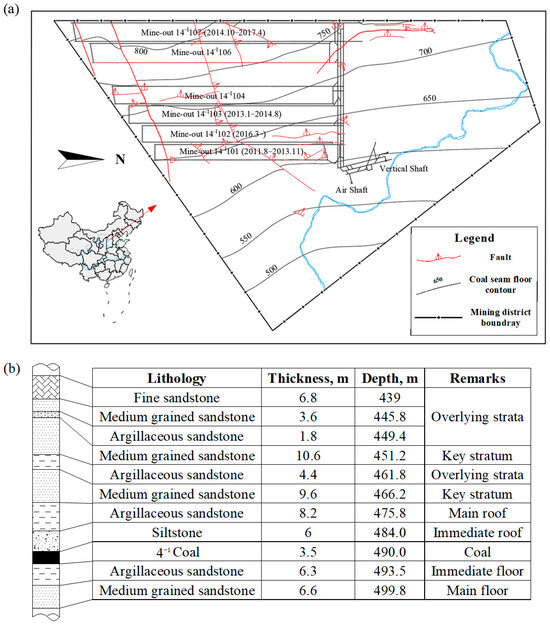
The Zhengli Coal Mine, located in the Lan country in Shanxi Province, has an annual output of 1.5 million tons. The 4−1 coal seam in this mine has a burial depth of approximately 490 m and an average thickness of 3.5 m. The immediate roof of the coal seam is siltstone, while the main roof is medium-grained sandstone. And there is no aquifer within the overlying strata, meaning the roof rock mass exists in a completely water-free environment. The borehole lithologic column is illustrated in Figure 1. At present, the 14−1106 working face is under extraction, with the 14−1105 working face remaining to be mined. Previously, the width of the coal pillars in this mine ranged from 15 m to 20 m. However, the unreasonable design of pillar width prevented the roadway from avoiding the peak of lateral stress, resulting in considerable difficulties in roadway excavation and subsequent maintenance.
Figure 1.
Mine working face layout and generalized stratigraphic column: (a) location of the test areas; (b) generalized stratigraphic column of the test site.
In this study, the headentry of the 14−1105 working face is selected as the research object. The roadway has a length of 566 m and adopts a rectangular cross-section, with an excavation width of 4.6 m and an excavation height of 3.2 m. The excavation is planned along the edge of the gob formed by the 14−1106 working face.
2.2. Current Status of Roadway Maintenance
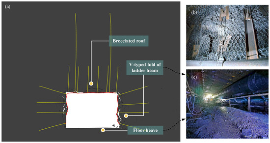
Under the layout of 15 m wide coal pillars and the current support scheme, the roadway maintenance and control status is presented in Figure 2. The current support scheme adopts a combined bolt-cable support system. Specifically, six Φ20 × 2200 mm bolts are arranged, with a row spacing of 800 mm × 1000 mm; every two rows of bolts are equipped with two or three Φ18.96 × 6500 mm cables. Four bolts are installed in each rib row. The pre-tightening forces of the bolts and cables are 60 kN and 300 kN, respectively.
Figure 2.
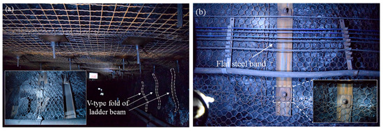
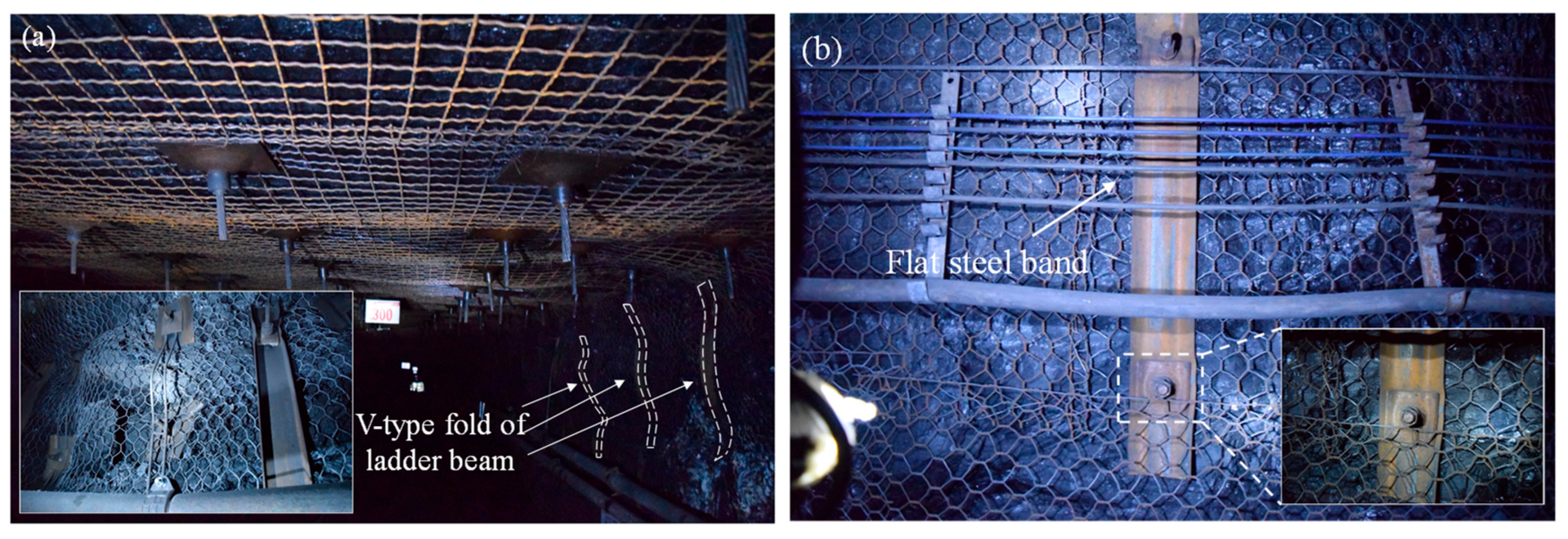
Roadway maintenance and control status: (a) deformation of roadway surrounding rock; (b) ladder beam distortion; (c) floor heave.
Figure 2b,c present actual photographs of the current status of roadway maintenance. As observed from these images, the roof surface is severely fractured, with rock fragments falling in a string-bag shape; passive support components are lifted. The above maintenance status indicates that the deformation is significant.
3. Weighting Mechanism of Lateral Roof Structure and Distribution Characteristics of Internal and External Stress Field in Gob-Side Entry
3.1. Mechanical Model of Surrounding Rock Structure of GSED-NP
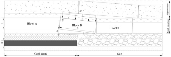
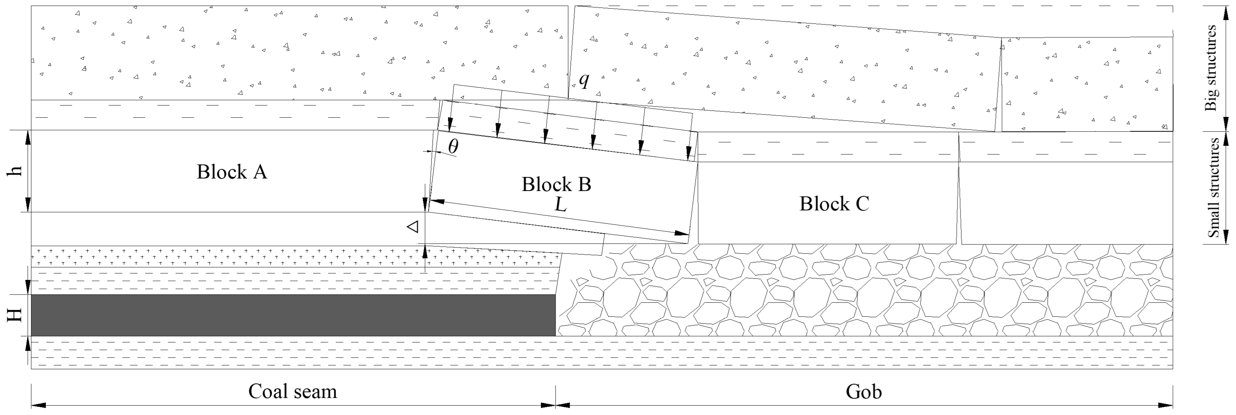
The key stratum is broken in the coal body of the next face and forms an arc-shaped triangular block B laterally on the working face (Figure 3) after the upper working face was mined. Block B rotates and subsides toward the goaf direction under the weight and upper load, with the main roof fracture line serving as the rotational axis, and is extruded and hinged with block A and block C to form a lateral voussoir beam. The stable voussoir beam structure can bear most of the overburden weight [17], and transfers the overlying rock load to the gangue deep in the coal wall and the goaf through the support points, which forms an abutment pressure in this area. Notably, this kinematic behavior of block B (rotation and subsidence) induces the formation of a delamination space within the overlying strata, thereby triggering stress shunting effects. It is this stress shunting mechanism that explains why the coal wall under the voussoir beam structure forms a stress lower than in situ stress in Figure 3.
Figure 3.
Overburden structure of GSED-NP.
3.1.1. Kinematic and Dynamic Equations of the Voussoir Beam
To ensure the theoretical derivation is solvable and closely reflects engineering practice, the mechanical model was established under specific assumptions and boundary conditions. Regarding the rock mass behavior and key-strata fracture, the multi-layer thick-hard strata are simplified into a continuous, homogeneous elastic beam, which is assumed to fracture into discrete interacting blocks once its ultimate tensile strength is exceeded. Considering that the roadway is in a plane strain state, the stress and deformation can be simplified to a plane for analysis. For the boundary conditions, the upper boundary is subjected to an equivalent uniformly distributed load from the overlying strata; the lower boundary rests on a deformable foundation consisting of the solid coal and caved gangue; and the lateral boundaries are constrained by the semi-infinite solid coal mass and the hinged structure, respectively.
After the multi-layer main roof fractures, block B rotates and subsides towards the goaf by an angle θ. According to the “S-R” (Sliding-Rotation) stability theory [17], block B, the unbroken rock strata and the caved gangue together form a hinged beam. The maximum subsidence at the hinge point can be expressed as:
where L is the block length, and θ is the rotation angle.
To prevent structure sliding instability, a horizontal compressive thrust T acts on the contact surfaces. Based on the moment equilibrium condition (ΣM = 0) at the hinge point, the relationship between the horizontal thrust T and the rotation angle θ is derived as:
where q is the equivalent overlying load, and h is the stratum thickness.
As indicated by the equation, with the increase of the θ, the Δ increases, leading to a decrease in the lever arm (h − Δ). Consequently, the horizontal thrust T required to maintain stability increases non-linearly. The transmission of this massive horizontal thrust T and the shear force V to the deep solid coal (block A) is the fundamental source of the severe lateral abutment pressure in GSED-NP.
3.1.2. Evolution of the IESF Distribution
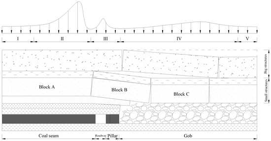
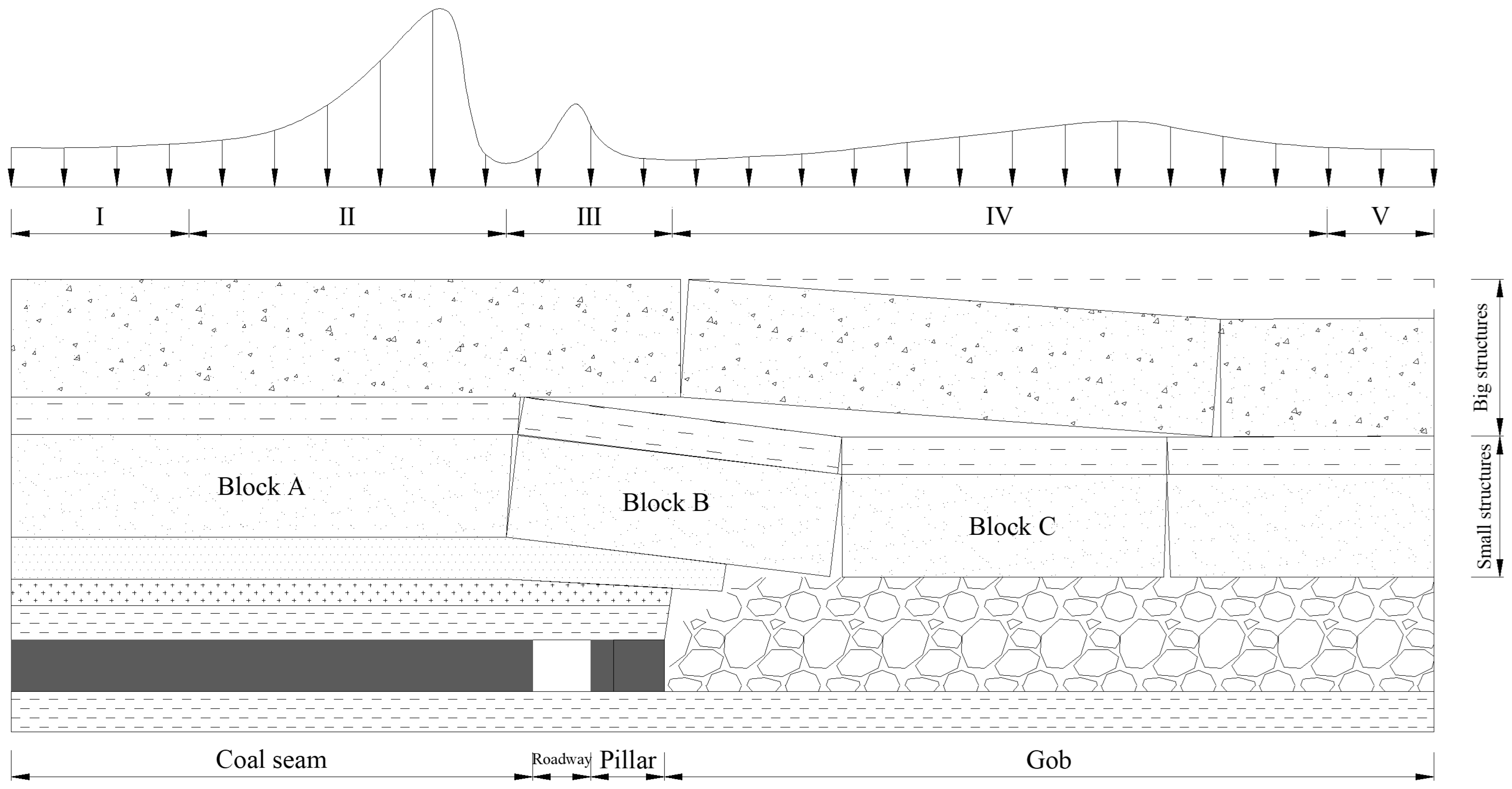
Fracture of “big structure” fundamentally reshapes the stress environment around roadway, driving the evolution from a single stress concentration to a dual-zone distribution (“internal” and “external” stress fields).
Before the thick sandstone layers fracture, the main roof bears the overburden load. The vertical stress σv highly concentrates near the coal wall rib, which can be described as:
where k is the dynamic stress concentration factor (k > 1), γ is the average unit weight, and H is the mining depth. At this stage, the peak stress is located extremely close to the coal wall, making roadway excavation extremely dangerous.
Once the voussoir beam is formed, the fracture line typically occurs deep within the solid coal. The load transfer path diverges, causing a sudden shift in the stress peak position:
The overburden weight (q) is transferred into unbroken rock mass deep inside the solid coal through the hinge point. This forms the “external stress field,” moving the peak stress into deeper strata. The peak stress here is σ = KγH (where K > k).
Internal Stress Field (Stress-relief zone): The area directly beneath the fractured block B is shielded by the hinged arch. This area primarily bears the residual weight of the immediate roof, forming a low-stress “internal stress field.” The vertical stress here drops significantly below the in situ stress:
Therefore, if the roadway is arranged in the internal stress field, the lateral abutment pressure peak can be effectively avoided for the purpose of pressure avoidance. It can be concluded that the distribution range of the low-stress zone is primarily governed by the fracture position of the key roof.
For the 14−1105 working face, medium-grained sandstone layers of 9.60 m and 10.65 m thick constitute the key roof. The lateral rock structure and stress partition are shown in Figure 4.
Figure 4.
Mechanical model of surrounding rock structure of GSED-NP.
3.2. Numerical Simulation Quantitative Research
As mentioned above, the fracture movement of the 9.60 m and 10.65 m thick medium grained sandstones will affect the stress distribution after the working face 14−1106 is extracted. Therefore, the UDEC 7.0 was used for quantitatively analyzing the influence of structural fracture of the and its re-stabilization on surrounding rock stress.
3.2.1. Numerical Model Establishment
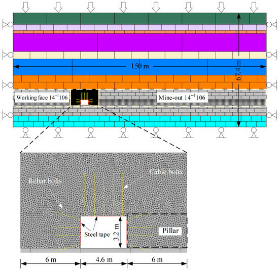
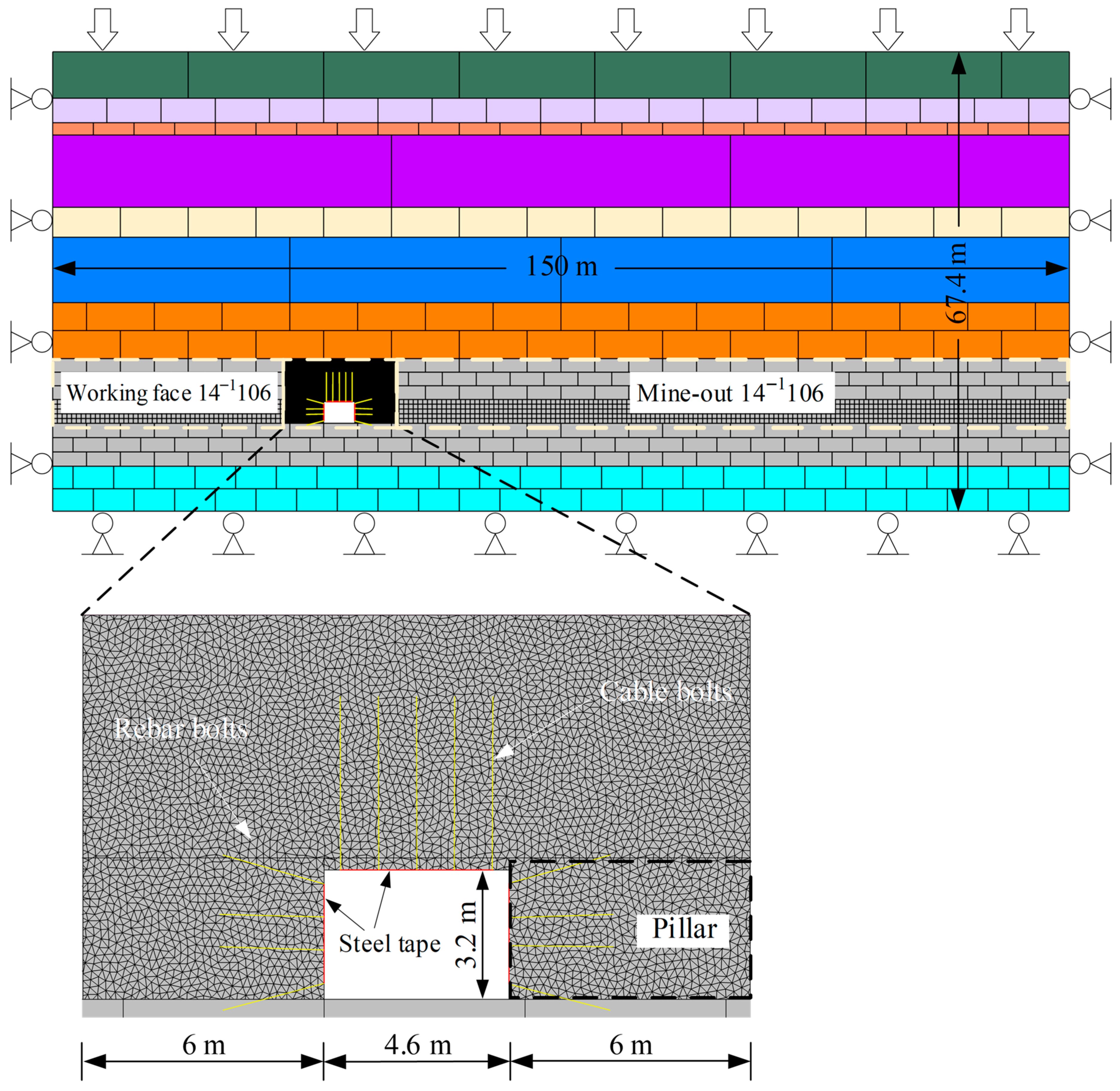
To realistically simulate the discontinuous brittle fracture and large volumetric expansion of the multi-layer thick and hard roof, the UDEC Trigon approach was employed, overcoming the limitations of conventional continuum models in capturing crack propagation. The global model dimensions were set to 150 m × 67.4 m. Numerical monitoring confirmed this size was sufficient to eliminate artificial boundary effects. The lateral and bottom boundaries were fixed horizontally and vertically, respectively, while a 9.59 MPa vertical stress was applied to the top boundary. A mesh sensitivity analysis determined an optimal block size of 0.2 m for the region of interest. Coarser meshes failed to capture complex cracks, while finer meshes caused unacceptable computational costs; therefore, gradually increasing block sizes were used outwards.
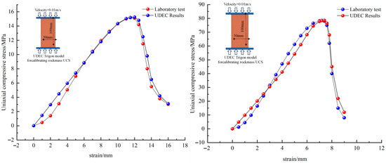
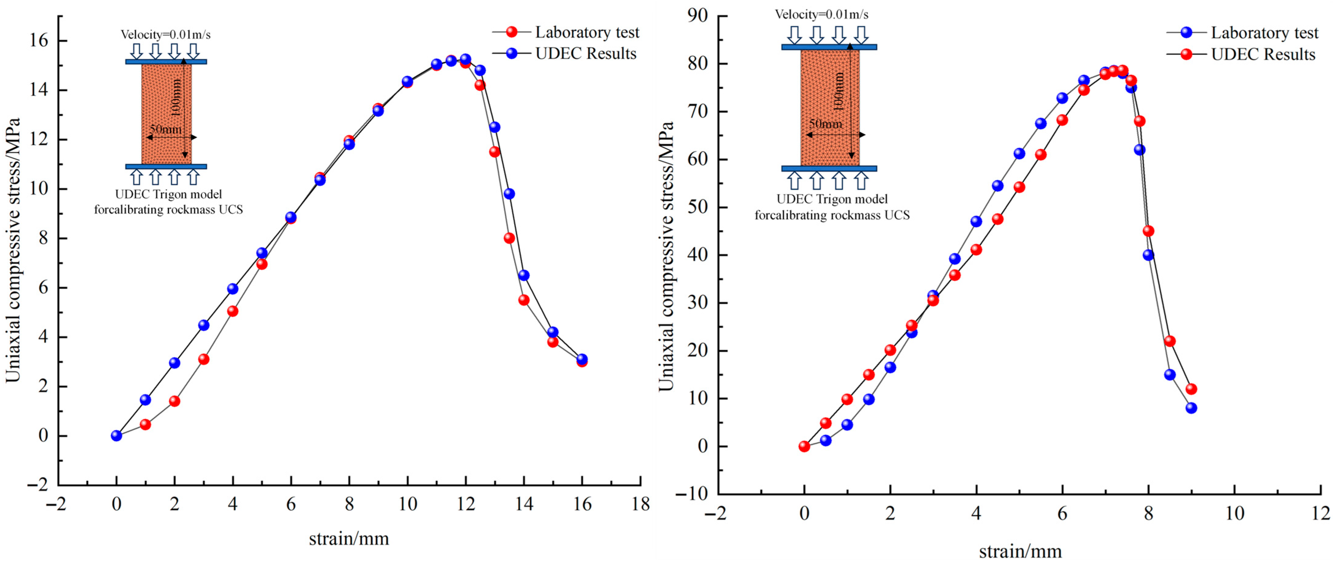
It is widely recognized that the micro-parameters required for the UDEC Trigon model cannot be directly obtained from conventional macroscopic laboratory tests. To bridge this gap, an iterative calibration procedure simulating Uniaxial Compressive Strength (UCS) tests was conducted prior to the field-scale simulation. Following the suggested methods by ISRM, standard numerical rock specimens with dimensions of 50 mm × 100 mm were established. Crucially, the triangular block sizes within these specimens were kept consistent with the refined mesh size 0.2 m used in the global model to eliminate the scale effect of the micro-parameters. Micro-parameters were calibrated by trial and error until the simulated stress–strain curves and brittle failure modes agreed well with laboratory results. As shown in Figure 5, the numerical stress–strain responses and failure patterns of coal and roof rock are highly consistent with experimental data. The final calibrated micro-parameters are listed in Table 1. And the parameters of the Trigion model were adopted from the literature [7], as listed in Table 2.
Figure 5.
Calibration of the UDEC Trigon micro-parameters via simulated UCS tests.
Table 1.
Rock strata properties.
Table 2.
Properties in Trigon model (Data from [7]).
With the model geometry and calibrated parameters established, the numerical analysis was rigorously executed through the following sequential steps: (1) implementing and initializing the in situ stress field to reach initial equilibrium; (2) extracting the adjacent 14−1106 working face in retreat to form the lateral abutment pressure; (3) stepping the model to solution to allow for roof caving and stress redistribution; (4) excavating the headentry and applying the support; and (5) stepping to final solution to evaluate the support performance, as shown in Figure 6.
Figure 6.
Sketch of the UDEC model.
3.2.2. Structure and Stress Transfer of BSVB
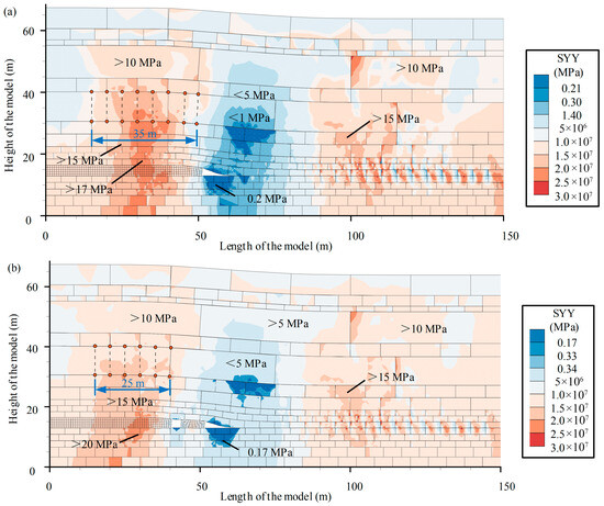
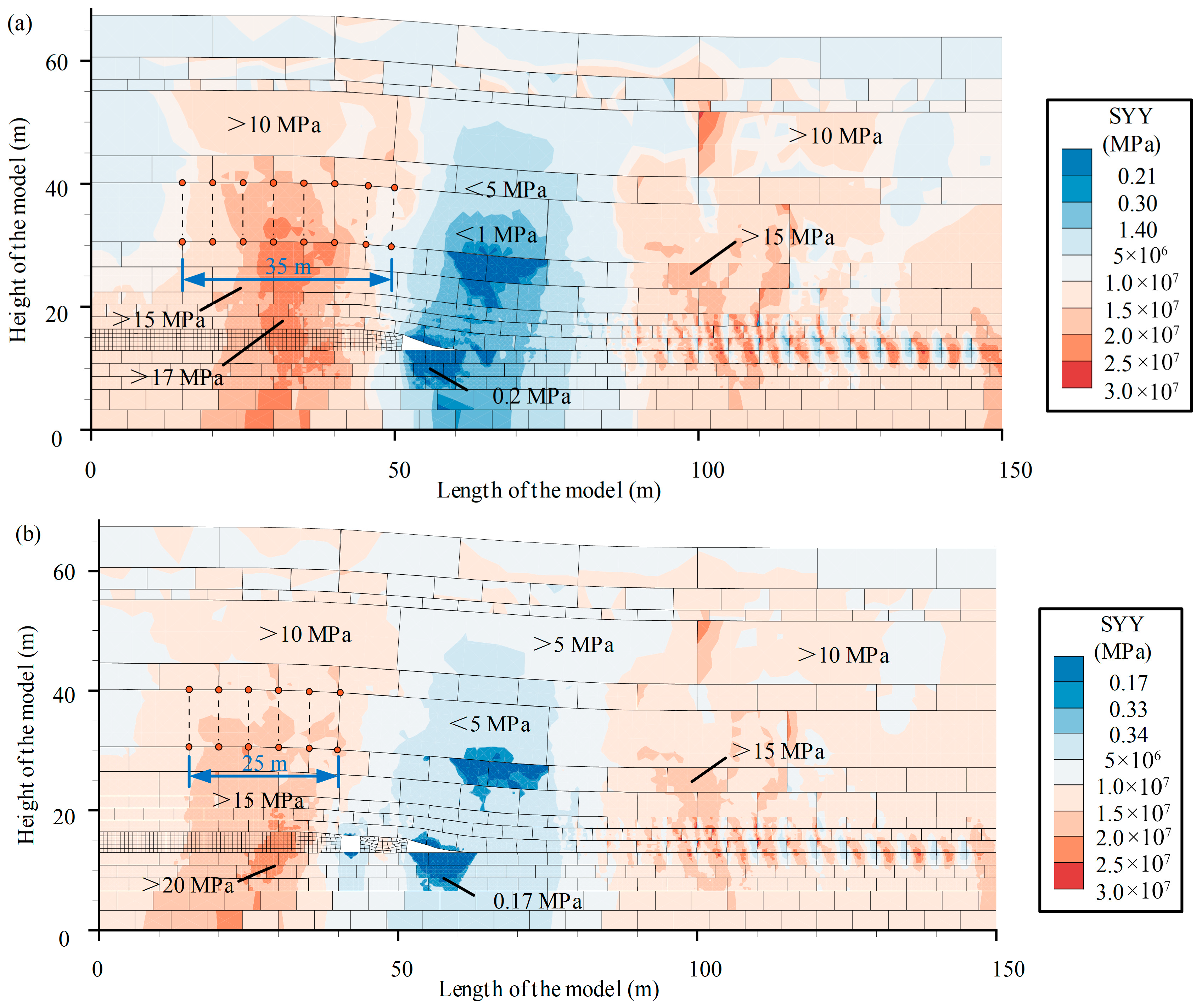
After mining the working face 14−1106, the 9.60 m and 10.65 m thick medium grained sandstone fractured in the coal body (Figure 7). One end of the block B rotates and subsides towards goaf, while the other end breaks in the coal body, and is mutually extruded and hinged with block A and C, respectively forming a lateral voussoir beam. The stabilized structure can transfer the overlying rock weight to the gangue in the depths of the coal wall and the goaf through the support points, forming a higher stress in this area, while the coal wall below the voussoir beam structure forms a low stress zone.
Figure 7.
Numerical simulation results of the BSVB structure and stress distribution: (a) before roadway excavation; (b) after roadway excavation.
3.2.3. Distribution of IESF
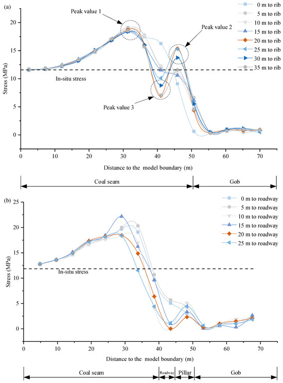
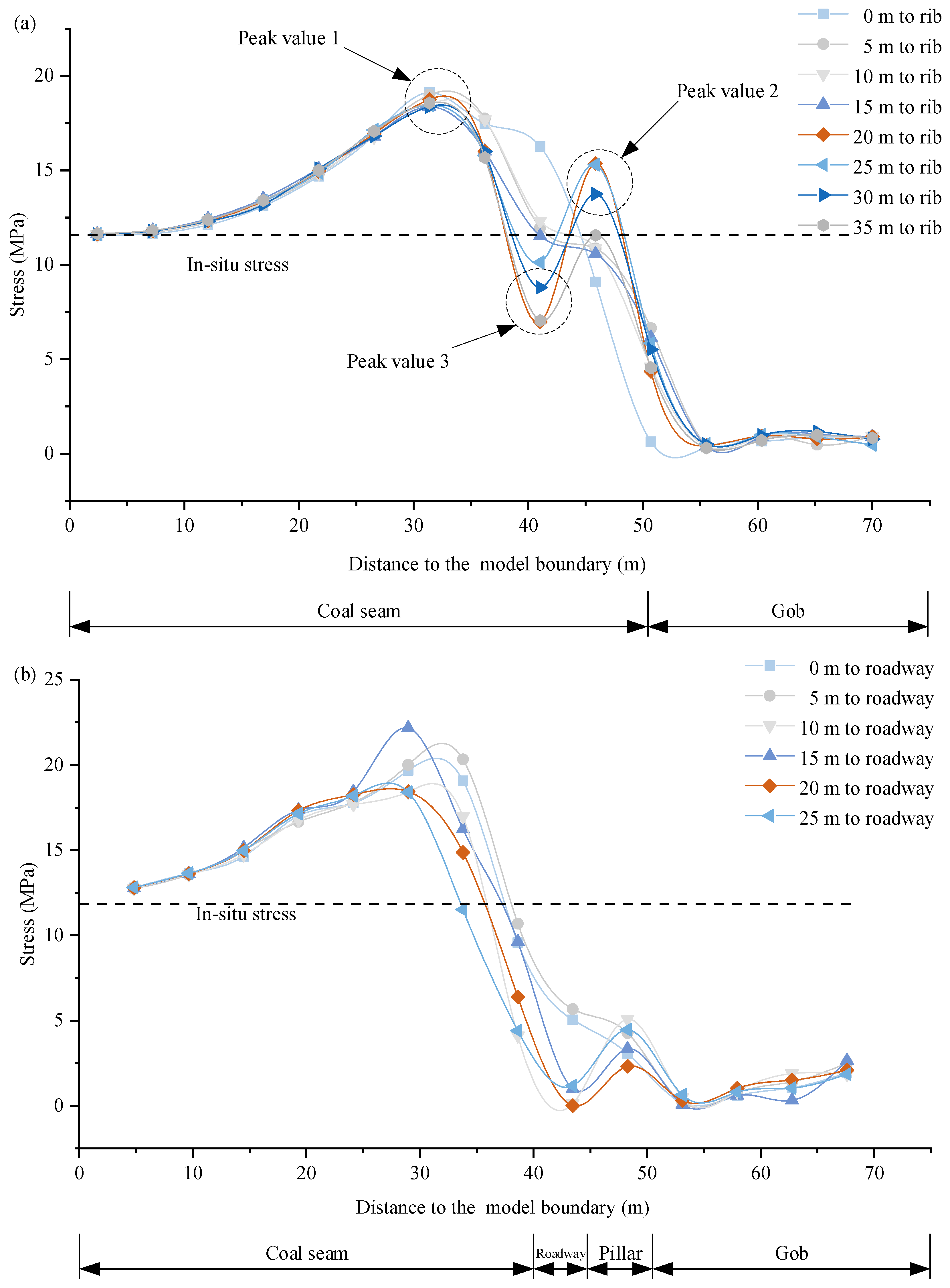
Figure 8 shows the double-peak distribution characteristics and the shielding effect of the small structure. When the fracture position of 9.60 m thick stratum is 0 m and 5 m to the roadway, the stress curve exhibits a single-peak distribution, and the changing trend increases first and then decreases. However, when the fracture position of stratum is 10 m, 15 m, 20 m, and 25 m to the roadway, the stress curve exhibits a double-peak distribution. This indicates that the voussoir beam forms after the fracture of the 9.60 m thick medium grained sandstone above the working face.
Figure 8.
Lateral vertical stress distribution of goaf: (a) before roadway excavated; (b) after roadway excavated.
4. Simulation and Determination of Pillar Width and Supporting Scheme
4.1. Simulation and Determination of Pillar Width
To grasp the rock deformation under different pillar width, a numerical simulation adjusting the pillar width of 2 m, 6 m and 16 m was conducted.
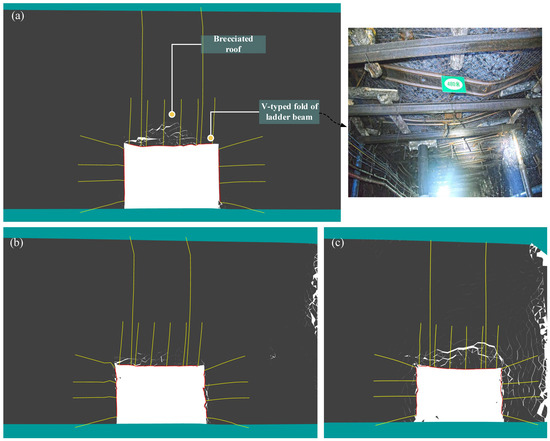
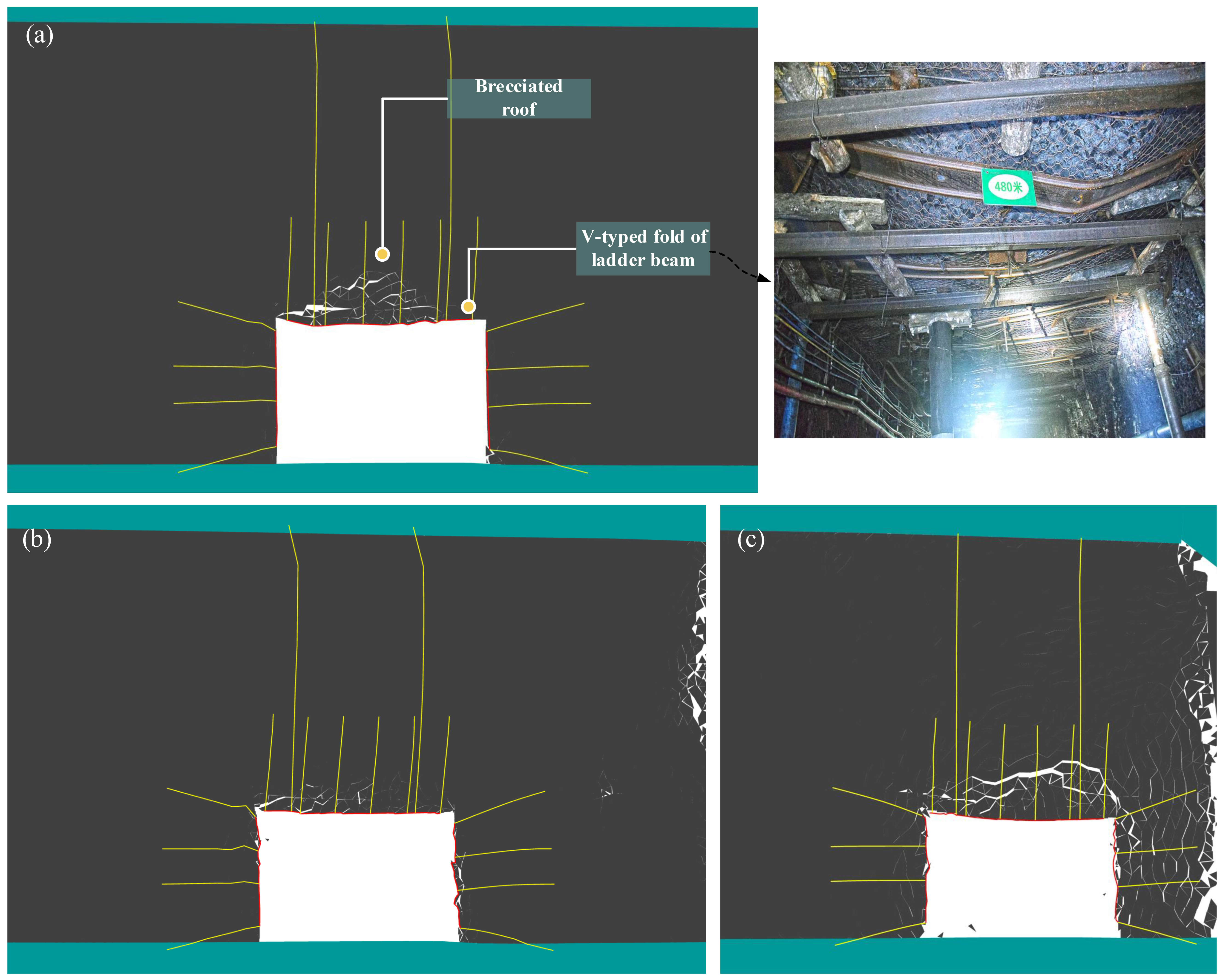
As shown in Figure 9a, the roof is seriously fragmented when the pillar width is 16 m. Finally, the cracks run through to form a triangular damaged zone with a maximum value of 1.13 m. The rock masses within 1 m of the surface undergo failure and collapse, and the steel band are bent into a V-shape. Meanwhile, no fissure development exists in the rocks of the two sides, and the passive supporting members are not deformed. Overall, when the pillar width is 16 m, roadway deformation mainly occurs in the roof, and the rib stability is well controlled.
Figure 9.
Numerical simulation results of roadway deformation in original supporting scheme when roadway is located in different position: (a) 16 m coal pillar width; (b) 6 m coal pillar width; (c) 2 m coal pillar width.
As shown in Figure 9b, the roof can be kept flat when the pillar width is 6 m. Compared with Figure 9a, the failure range is significantly reduced, the maximum damaged zone is only 0.72 m only; the cracks are not connected. However, the deformation and the fissure development in rib are more evident. Obvious dilatation deformation occurs on the narrow pillar rib, which causes the passive supporting members to bend outwards. Overall, when the pillar width is 6 m, favorable surrounding rock control is achieved.
As shown in Figure 9c, the roof surface has obvious bending and subsidence when the pillar width is 2 m. Compared with the roadway arranged at 30 m, the fissure development in the roof is complete, and finally forms a trapezoid damaged zone along the crack channel, with the maximum damaged zone of 1.19 m, and delamination occurs, which indicates that the strata behaviors are the most serious in this area. The passive supporting member is deformed under tension. Vertical cleavage appears on the narrow pillar side, indicating that the narrow pillar is subjected to axial pressure.
On the whole, the bearing capacity is constantly improved with the pillar width increasing. However, when the pillar width exceeds a certain threshold, such as 16 m, the roadway will be in the stress-increasing area. Conversely, when the pillar width is excessively small (e.g., less than 2 m), the surrounding rock will undergo plastic deformation, resulting in ineffective anchoring and eventual failure. Accurate numerical results show that deliberately selecting a 6 m pillar allows the shallow region of the pillar adjacent to the goaf to undergo plastic yielding, further transferring the overlying load to the deep solid coal. More importantly, as the main roof fractures within the critical range of 5–10 m, setting the pillar width at 6 m ensures that the bulk of the roadway span remains effectively shielded by the low-stress internal field of the BSVB. The slight stress concentration on the rib of the 6 m pillar can be effectively managed by the TADL supporting technology, as the 6 m width is sufficient to provide a stable “elastic core” for the deep anchorage of flexible bolts and cables. This approach successfully bridges the theoretical optimum and practical engineering constraints. The relationship between lateral abutment pressure and the bearing capacity of coal pillar can be well-coordinated, which constitutes an optimal roadway maintenance state.
4.2. Determination of Supporting Scheme
4.2.1. TADL Supporting Technology
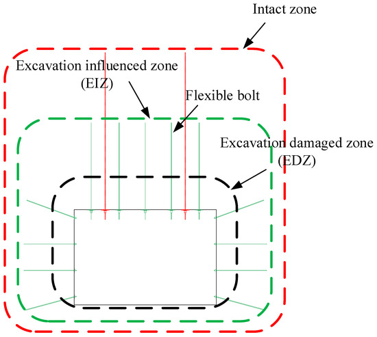
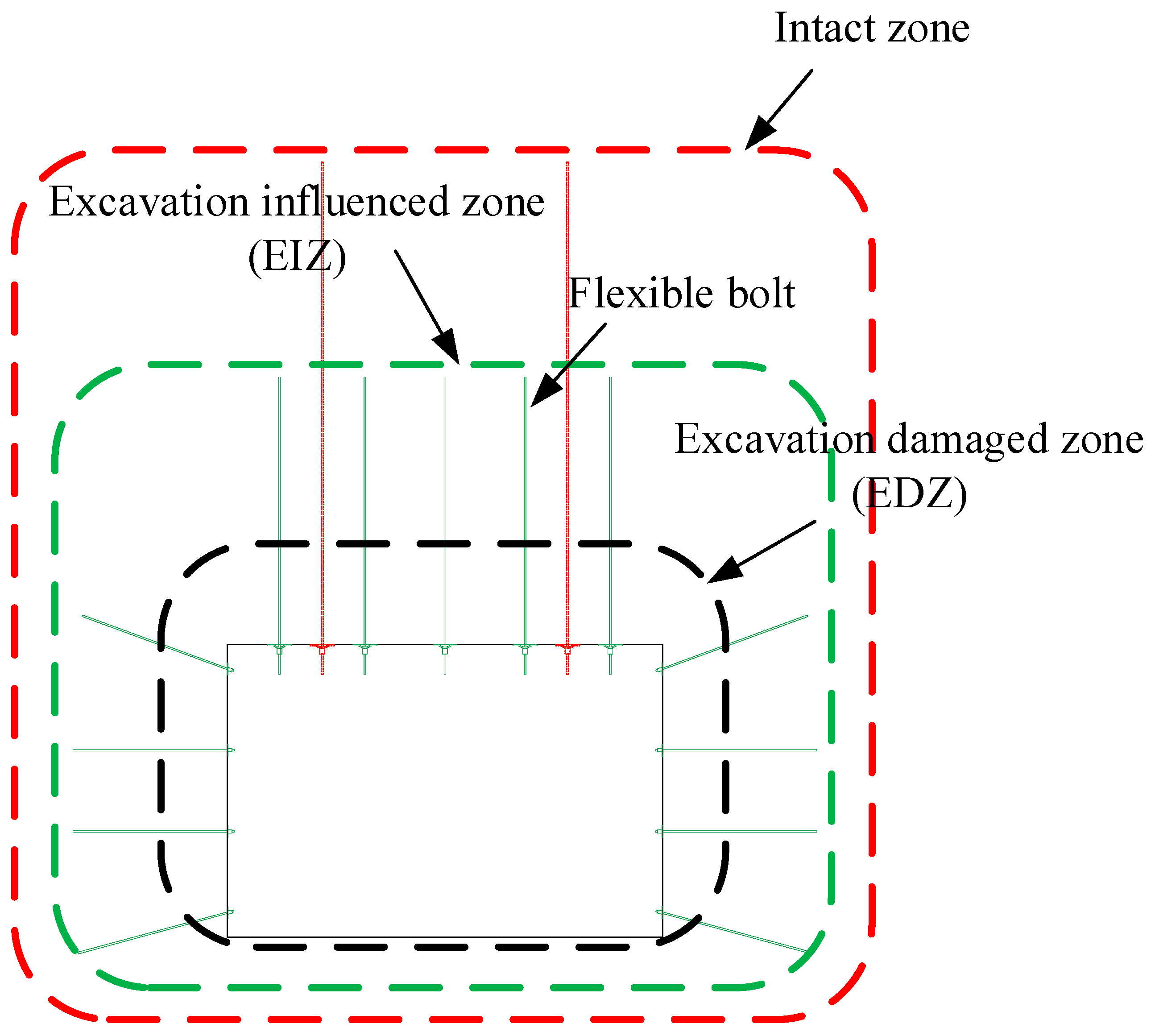
After roadway excavation, three distinct zones distribute around it [8,45]—the excavation damaged zone (EDZ), the excavation influenced zone (EIZ), and the intact zone [8,45]. According to the findings reported in the literature [8], the EDZ is an annular fractured zone formed under the impact of intense mining disturbances. In this zone, the original structure of the surrounding rock is severely damaged, and the rock mass strength is much lower than the peak strength. In the absence of external constraints, its load-bearing capacity will be completely lost. Therefore, the EDZ is the main control object of the support system. The EIZ is the rock with the less fracture development.
The rock in the Intact Zone is not affected by disturbance, which exhibits the highest anchorability, allowing the bolt anchorage force to be maximized. If the anchorage end of the bolt is located in this region, it can provide a stable anchoring force for all rock masses in the anchorage zone. This implies that once the shallow surrounding rock begins to deform, the deformation can be rapidly transferred to the stable strata deep in the surrounding rock through the bolt, thereby achieving uniform displacement distribution and reducing the loading pressure on the shallow surrounding rock.
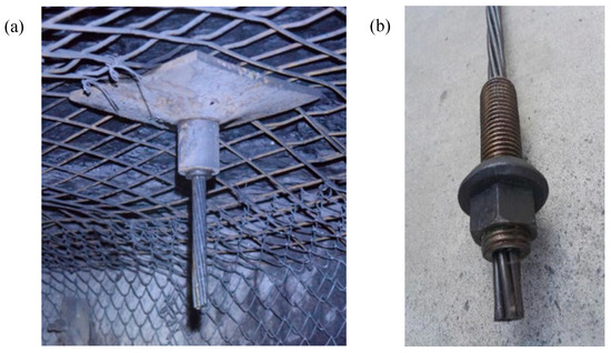
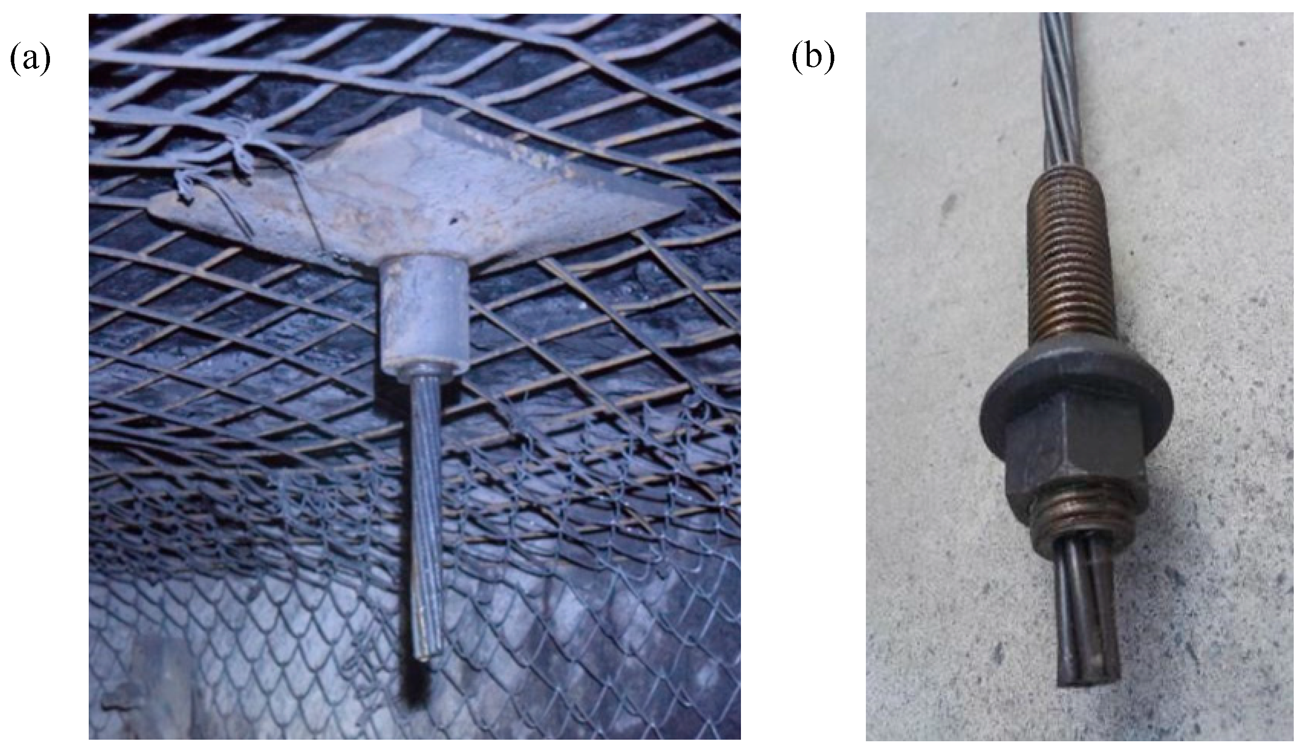
Based on the aforementioned analysis, the thick anchored dual-layer locking (TADL) supporting method is proposed (Figure 10 and Figure 11). The TADL technique consists of two sets of cables with different lengths: short cables range from 4.0 m to 4.3 m, and long cables range from 6.3 m to 7.3 m. The mechanical properties of the cables employed in the first layer support are presented in Table 3. The short cables are designed to integrate the shallow rock strata into an integrated prestressed beam with a thickness of 2.2–2.4 m, which is twice the length of short bolts. This results in a fourfold increase in flexural stiffness. In contrast, the long cables serve as the final safeguard of the support system, aiming to prevent collapse and caving of loose rock blocks.
Figure 10.
TADL supporting technology [4,46].
Figure 11.
Flexible bolts: (a) type I in which pre-tightening force is applied through the lockset; (b) type II in which pre-tightening force is applied through the nut [4,46].
Table 3.
Comparison of bolts performance parameters.
4.2.2. Supporting Scheme
As demonstrated in Figure 12, a TADL support scheme is proposed as follows. Each row is equipped with five Φ21.8 × 4300 mm flexible bolts, with a row spacing of 950 mm × 1000 mm. Every two rows of flexible bolts are supplemented with two Φ21.8 × 6300 mm cables, with a row spacing of 2850 mm × 2000 m. Rib support remains consistent with the existing scheme. The pre-tightening force of flexible bolts is 200 kN, and that of cables is 300 kN.
Figure 12.
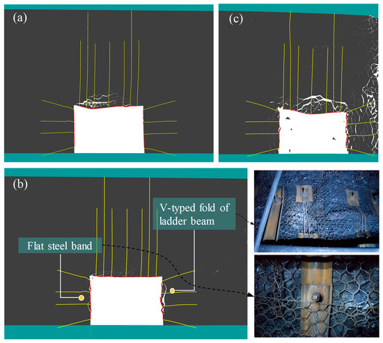
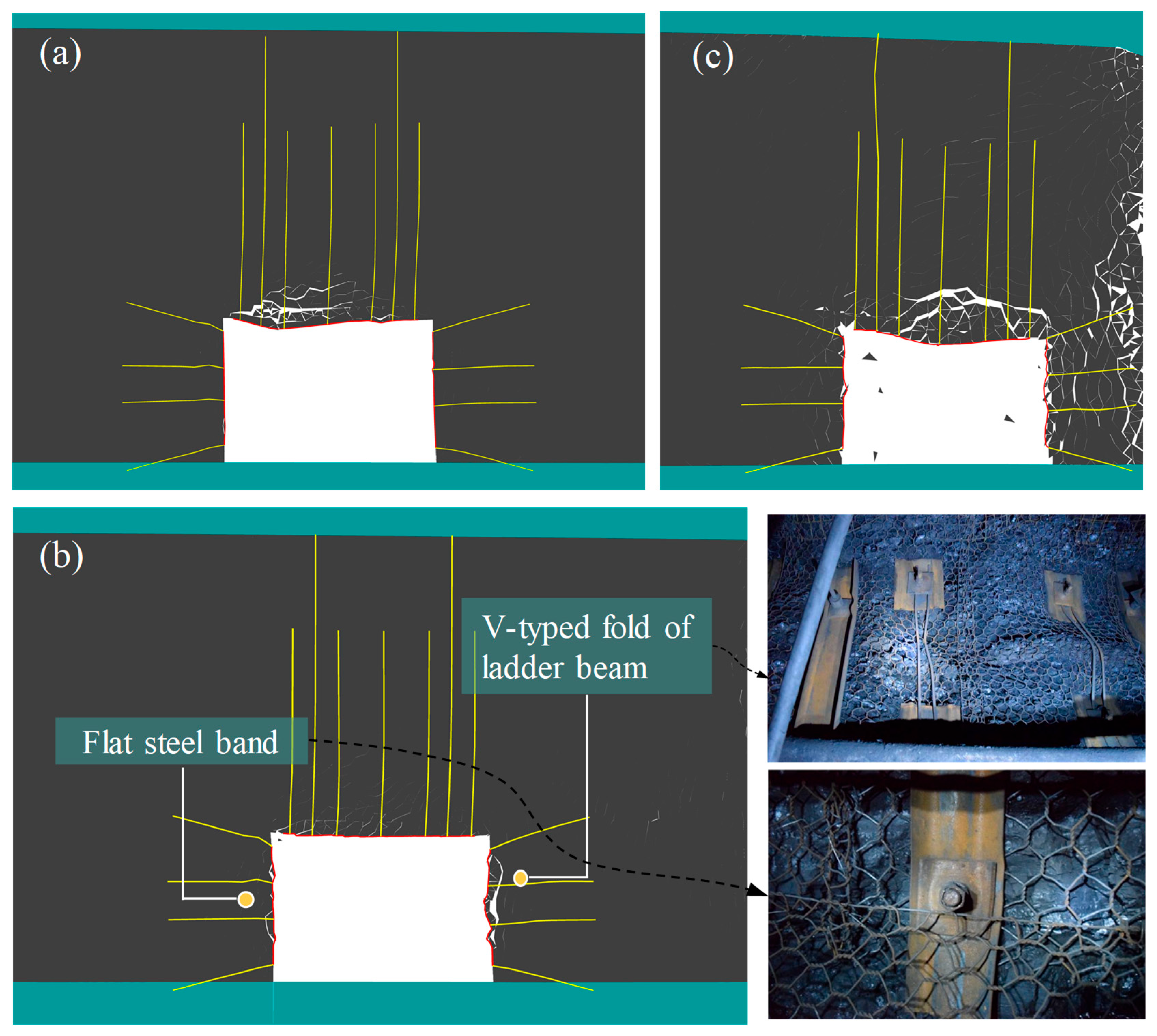
Numerical simulation results of roadway deformation in TADL supporting scheme when roadway is located in different position: (a) 16 m coal pillar width; (b) 6 m coal pillar width; (c) 2 m coal pillar width.
4.2.3. Simulation Results
Figure 12 shows the simulation results of the roadway deformation under different pillar widths with the TADL supporting technology.
As shown in Figure 12a, the roof has fractured to some extent when the pillar width is 16 m. Compared with Figure 9a, the fissure development and the final connection range are significantly reduced, and the maximum damaged area is reduced to 0.89 m. The two rock masses remain intact.
As shown in Figure 12b, the roof is be basically flat when the pillar width is 6 m. Compared with Figure 9b, the maximum damaged zone is reduced to 0.2 m. For the side wall deformation, the deformation of the narrow pillar side is significantly larger than the other. The ladder beam on the narrow pillar side is bent into V-shape, while the other side remains flat.
As shown in Figure 12c, the roadway surface is obviously fractured when the width pillar is 2 m. Compared with Figure 9c, the fissure finally forms a triangular damaged zone along the fractured channel, with the maximum damaged zone of 0.88 m.
To rigorously evaluate the surrounding rock control performance under the severe dynamic loads induced by the multi-layer thick and hard roof, a quantitative comparison was conducted between the original support scheme and the proposed TADL technology.
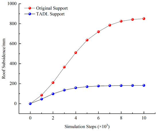
As illustrated in Figure 13, the original support failed to resist the continuous asymmetric weighting. The roof subsidence deteriorated rapidly without effective convergence. The maximum roof subsidence eventually reached 850.8 mm, and the rib-to-rib convergence expanded to approximately 620 mm. The continuous expansion of the plastic zone led to a maximum roof failure depth of 2.4 m, indicating a high risk of overall roadway instability.
Figure 13.
Comparison of the roof subsidence.
In striking contrast, the implementation of the TADL supporting technology successfully intercepted the massive deformation. As shown by the displacement evolution curves, the TADL system rapidly stabilized the surrounding rock after a brief initial energy-release phase. The maximum roof subsidence was strictly confined to 182.5 mm, representing a remarkable quantitative reduction of 78.5% compared to the original scheme. Similarly, the rib-to-rib convergence was drastically reduced by 65.3% to 215 mm. Furthermore, owing to the trans-boundary anchoring mechanism of the flexible bolts in the TADL system, the propagation of tensile and shear cracks was effectively suppressed, limiting the maximum depth of the roof failure zone to only 0.6 m.
On the whole, the scope of the damaged area of the roof is greatly reduced with the TADL supporting technology, and when the roadway is arranged at 40 m, the surrounding rock control effect is the best.
5. Verification of Engineering Project
Based on the above analysis, Headentry of 14−1105 should be driven along the edge of Mine-out 14−1106, with a pillar width of 6 m, and TADL supporting technology should be employed, with the supporting scheme in Section 4.2.2. Three sets of mine pressure monitoring schemes, including roadway displacement and cable working resistance, are arranged.
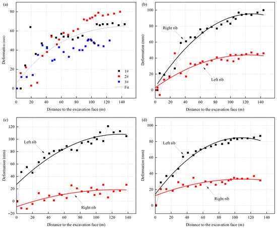
Figure 14 demonstrates the displacement monitoring data of three observation stations. The roof displacements of observation stations 1#, 2# and 3# are 67 mm, 80 mm and 50 mm, respectively. The displacements of the narrow pillar side and solid coal side of observation stations 1#, 2# and 3# are 100 mm, 46 mm, 105 mm, 28 mm and 87 mm, 28 mm, respectively. The stable values of the side wall movement of the narrow pillar are 215.34%, 544.79% and 283.85% of the side wall of solid coal, respectively, which is in good agreement with the numerical simulations.
Figure 14.
Measured roof deformation of headentry of 14–1105: (a) roof deformation; (b) rib deformation of observation stations 1#; (c) rib deformation of observation stations 2#; (d) rib deformation of observation stations 3#.
The bolt dynamometer is arranged within 1 m from the roof displacement observation station to monitor the working resistance. As listed in Table 4, among the three observation stations arranged, the growth rates of the support resistance on the narrow pillar side and the solid coal side of the observation stations 1#, 2# and 3# are 408.70%, 73.87%, 221.79% and 68.55%, 102.29%, 35.97% respectively, after the bolts are stabilized.
Table 4.
Working resistance of bolt.
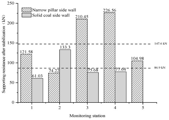
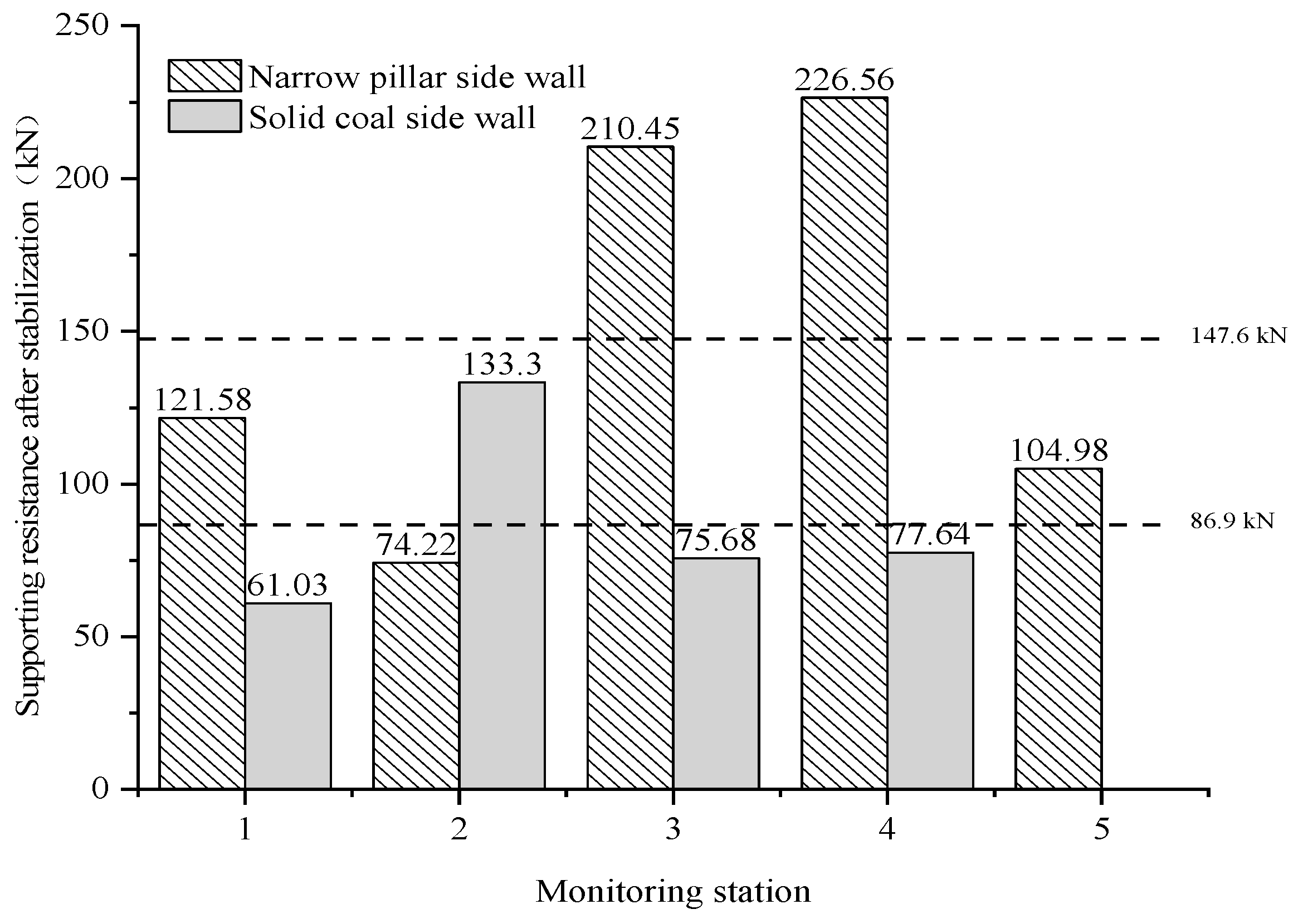
As shown in Figure 15, the average support resistance of flexible bolt on the side wall of the narrow pillar is 147.6 kN after bearing stability, while that of the solid coal is 86.9 kN. Under the action of the suspended ceiling load, plastic flow and lateral expansion occur, which drives the coal body to expand and extrude toward the free surface. Therefore, the growth rate of active supporting members in the narrow pillar side is obviously higher than the other side after the support resistance is stable.
Figure 15.
Comparison of the supporting resistance of flexible bolt and cable of narrow pillar side wall and solid coal side wall.
As shown in Figure 16, the roof and solid coal side have a good shaping effect, smooth surface, and no uneven deformation of support as the TADL supporting technology is applied. However, the coal on the narrow pillar side bulges outwards, leading to the extrusion deformation of passive supporting members, showing typical post-peak plastic flow deformation behavior after peak. Meanwhile, the side bolts and the elastic rock mass in the deep bearing core area can still be effectively anchored, and the bearing capacity is good, which greatly limits the lateral deformation of the shallow surrounding rock, indicating that the elastic core inside the narrow pillar effectively exists. The size of the coal pillar successfully avoided the lateral stress peak to some extent.
Figure 16.
Real photos of the roof and the two side supports: (a) roof; (b) sidewall.
6. Discussion
- (1)
- The distribution of IESF is closely associated with the fracture position of the main roof. Upon the main roof fracture, block B undergoes rotation and subsidence. This movement leads to the formation of a delamination space within the overlying strata, which induces stress shunting effects. As a consequence, a low-stress region is formed between the main roof fracture line and the coal wall, whereas a stress-enhanced region is generated within the main roof fracture line.
- (2)
- There exists a critical range for the main roof fracture position in terms of stress transfer. When the distance between the fracture position and the coal wall is less than 5 m, the low-stress area formed by the BSVB structure expands as the fracture line moves further away from the coal wall. Conversely, when this distance exceeds 10 m, the given deformation caused by the rotation and subsidence of the main roof on the coal wall will be greater, and the compressive deformation and dilatancy deformation caused to the coal wall will also be larger. Therefore, the critical range for the main roof fracture position is determined to be 5–10 m.
7. Conclusions
In this paper, the BSVB weighting mechanism in GSED-NP is analyzed, and the TADL supporting technology is proposed. And the following conclusions are obtained:
- (1)
- The 9.60 m and 10.65 m thick medium grained sandstone fractured in the coal body of the next face, and formed a BSVB structure through rotation, subsidence, and re-hinging.
- (2)
- Under the stress transfer effect of BSVB structure, the distribution of lateral abutment pressure is characterized by IESF distribution. When the fracture position of 9.60 m thick strata is 0 m and 5 m to the roadway, the lateral stress curve shows a single-peak distribution; while the fracture position is 10 m, 15 m, 20 m, and 25 m to the roadway, the lateral stress curve shows a double-peak distribution.
- (3)
- The critical fracture range of 5–10 m for the main roof enables effective stress shunting through delamination, thereby providing a quantitative criterion for optimizing the pillar width (e.g., 6 m) to ensure the roadway remains safely within the low-stress zone.
- (4)
- The TADL supporting technology serves as an effective control method in GSED-NP.
Author Contributions
Conceptualization, Y.Y. and J.W.; Methodology, G.H. and X.Y.; Software, J.X.; Validation, Y.L., B.Z. and P.Y.; Investigation, S.L. and Q.D.; Data Curation, Z.L. and G.L.; Writing—Original Draft, F.Y. and Z.W.; Writing—Review and Editing, L.Z. All authors have read and agreed to the published version of the manuscript.
Funding
This research was funded by the National Natural Science Foundation of China (No. 52504104) and 75th batch of China Post-doctoral Science Fund (2024M752606).
Data Availability Statement
The original contributions presented in this study are included in the article. Further inquiries can be directed to the corresponding author.
Conflicts of Interest
Authors Yunfeng Liang, Baoyan Zhi, Pengmin Yang, Xinping Yang, Jinguo Wang, Zixiong Li, Shichang Liang, Qiuwei Dai, Genqiao Li, Feng You, and Zhiyao Wang were employed by the Dahaize Coal Mine, China Coal Shaanxi Yulin Energy & Chemical Industry Co., Ltd. Authors Lei Zhu, Gang Han, and Jiahao Xie were employed by the China Coal Energy Research Institute Co., Ltd. The remaining author declares that the research was conducted in the absence of any commercial or financial relationships that could be construed as a potential conflict of interest. The China Coal Shaanxi Yulin Energy & Chemical Industry Co., Ltd. and China Coal Energy Research Institute Co., Ltd. had no role in the design of the study; in the collection, analyses, or interpretation of data; in the writing of the manuscript, or in the decision to publish the results.
Abbreviations
The following abbreviations are used in this manuscript:
| BSVB | big and small voussoir beam |
| EDZ | excavation disturbed zone |
| EIZ | excavation impact zone |
| GSED-NP | gob-side entry driving with the narrow pillar |
| TADL | thick anchored dual-layer locking |
| IESF | internal and external stress field |
References
- Bai, J.B.; Shen, W.L.; Guo, G.L.; Wang, X.Y.; Yu, Y. Roof Deformation, Failure Characteristics, and Preventive Techniques of Gob-Side Entry Driving Heading Adjacent to the Advancing Working Face. Rock Mech. Rock Eng. 2015, 48, 2447–2458. [Google Scholar] [CrossRef] [Scilit]
- Feng, G.R.; Wang, P.F. Stress environment of entry driven along gob-side through numerical simulation incorporating the angle of break. Int. J. Min. Sci. Technol. 2020, 30, 189–196. [Google Scholar] [CrossRef] [Scilit]
- Zha, W.H.; Shi, H.; Liu, S.; Kang, C.H. Surrounding rock control of gob-side entry driving with narrow coal pillar and roadway side sealing technology in Yangliu Coal Mine. Int. J. Min. Sci. Technol. 2017, 27, 819–823. [Google Scholar] [CrossRef] [Scilit]
- Yuan, Y.X.; Han, C.L.; Zhang, N.; Feng, X.W.; Wang, P.; Song, K.; Wei, M. Zonal Disintegration Characteristics of Roadway Roof Under Strong Mining Conditions and Mechanism of Thick Anchored and Trans-boundary Supporting. Rock Mech. Rock Eng. 2021, 55, 297–315. [Google Scholar] [CrossRef] [Scilit]
- Cai, W.; Bai, X.X.; Si, G.Y.; Cao, W.; Gong, S.Y.; Dou, L.M. A Monitoring Investigation into Rock Burst Mechanism Based on the Coupled Theory of Static and Dynamic Stresses. Rock Mech. Rock Eng. 2020, 53, 5451–5471. [Google Scholar] [CrossRef] [Scilit]
- Han, C.L.; Zhang, N.; Xue, J.H.; Kan, J.G.; Zhao, Y.M. Multiple and Long-Term Disturbance of Gob-Side Entry Retaining by Grouped Roof Collapse and an Innovative Adaptive Technology. Rock Mech. Rock Eng. 2019, 52, 2761–2773. [Google Scholar] [CrossRef] [Scilit]
- Gao, F.Q.; Stead, D.; Kang, H.P. Numerical Simulation of Squeezing Failure in a Coal Mine Roadway due to Mining-Induced Stresses. Rock Mech. Rock Eng. 2015, 48, 1635–1645. [Google Scholar] [CrossRef] [Scilit]
- Wang, H.W.; Jiang, Y.D.; Xue, S.; Shen, B.; Wang, C.; Lv, J.; Yang, T. Assessment of excavation damaged zone around roadways under dynamic pressure induced by an active mining process. Int. J. Rock Mech. Min. Sci. 2015, 77, 265–277. [Google Scholar] [CrossRef] [Scilit]
- Wang, Q.; He, M.C.; Li, S.C.; Jiang, Z.H.; Wang, Y.; Qin, Q.; Jiang, B. Comparative study of model tests on automatically formed roadway and gob-side entry driving in deep coal mines. Int. J. Min. Sci. Technol. 2021, 31, 591–601. [Google Scholar] [CrossRef] [Scilit]
- Wang, Y.J.; Wang, Q.; Tian, X.C.; Wang, H.S.; Yang, J.; He, M.C. Stress and deformation evolution characteristics of gob-side entry retained by roof cutting and pressure relief. Tunn. Undergr. Space Technol. 2022, 123, 104419. [Google Scholar] [CrossRef] [Scilit]
- Chen, Y.; Ma, S.Q.; Yu, Y. Stability Control of Underground Roadways Subjected to Stresses Caused by Extraction of a 10-m-Thick Coal Seam: A Case Study. Rock Mech. Rock Eng. 2017, 50, 2511–2520. [Google Scholar] [CrossRef] [Scilit]
- Li, X.H.; Ju, M.H.; Yao, Q.L.; Zhou, J.; Chong, Z.H. Numerical Investigation of the Effect of the Location of Critical Rock Block Fracture on Crack Evolution in a Gob-side Filling Wall. Rock Mech. Rock Eng. 2016, 49, 1041–1058. [Google Scholar] [CrossRef] [Scilit]
- Zhang, G.C.; He, F.L.; Jia, H.G.; Lai, Y.H. Analysis of Gateroad Stability in Relation to Yield Pillar Size: A Case Study. Rock Mech. Rock Eng. 2017, 50, 1263–1278. [Google Scholar] [CrossRef] [Scilit]
- Jiang, F.X.; Zhang, X.M.; Yang, S.H.; Xun, L.; Ma, Q.H.; Wang, H.J. Discussion on overlying strata spatial structures of longwall in coal mine. Chin. J. Rock Mech. Eng. 2006, 5, 979–984, (In Chinese with English Abstract). [Google Scholar]
- Wang, C.W.; Jiang, F.X.; Sun, Q.G.; Sun, C.J.; Zhang, M.; Ji, Z.W.; Zhang, X.F. The forecasting method of rock-burst and the application based on overlying multi-strata spatial structure theory. J. China Coal Soc. 2009, 34, 150–155, (In Chinese with English Abstract). [Google Scholar] [CrossRef]
- Tan, Y.L.; Li, X.B.; Liu, X.S.; Fan, D.Y.; Song, S.L.; Zhang, Y.; Song, H. Disaster mechanism induced by overburden structure and control techniques for close-distance coal seam group. J. China Coal Soc. 2026, 51, 314–337, (In Chinese with English Abstract). [Google Scholar] [CrossRef]
- Tan, Y.L.; Zhang, X.F.; Fan, D.Y.; Liu, X.S.; Zhu, S.T.; Mu, Z.L.; Chen, Y. Mechanism and practice of structural modification to lateral overlying strata in gob-side entry for rockburst prevention. J. China Coal Soc. 2025, 50, 209–223, (In Chinese with English Abstract). [Google Scholar] [CrossRef]
- Qian, M.G.; Zhang, D.L.; Li, L.J.; Kang, L.X.; Xu, J.L. “S-R” stability for the Voussoir Beam and its application. Ground Press. Strata Control 1994, 3, 6–11+80, (In Chinese with English Abstract). [Google Scholar]
- Zhu, W.B.; Xu, J.M.; Xu, J.L.; Chen, D.Y.; Shi, J.X. Pier-column backfill mining technology for controlling surface subsidence. Int. J. Rock Mech. Min. Sci. 2017, 96, 58–65. [Google Scholar] [CrossRef] [Scilit]
- Zhu, W.B.; Chen, L.; Zhou, Z.L.; Shen, B.T.; Xu, Y. Failure Propagation of Pillars and Roof in a Room and Pillar Mine Induced by Longwall Mining in the Lower Seam. Rock Mech. Rock Eng. 2019, 52, 1193–1209. [Google Scholar] [CrossRef] [Scilit]
- Huang, B.X.; Liu, J.W.; Zhang, Q. The reasonable breaking location of overhanging hard roof for directional hydraulic fracturing to control strong strata behaviors of gob-side entry. Int. J. Rock Mech. Min. Sci. 2018, 103, 1–11. [Google Scholar] [CrossRef] [Scilit]
- Liu, J.W.; Liu, C.Y.; Yao, Q.L.; Si, G.Y. The position of hydraulic fracturing to initiate vertical fractures in hard hanging roof for stress relief. Int. J. Rock Mech. Min. Sci. 2020, 132, 104328. [Google Scholar] [CrossRef] [Scilit]
- Hou, C.J.; Li, X.H. Stability principle of big and small structures of rock surrounding roadway driven along goaf in fully mechanized top coal caving face. J. China Coal Soc. 2001, 1, 1–7, (In Chinese with English Abstract). [Google Scholar]
- Zhu, L.; Yao, Q.L.; Xia, Z.; Wang, W.N.; Li, X.H. Study on the movement characteristics of the overlying stratum and surrounding rock control in ultraclose coal seams: A case study. Energy Sci. Eng. 2020, 8, 1231–1246. [Google Scholar] [CrossRef] [Scilit]
- Brady, B.H.G.; Brown, E.T. Rock Mechanics for Underground Mining; Springer: Berlin/Heidelberg, Germany, 2004. (In Chinese) [Google Scholar]
- Yao, Q.L.; Li, X.H.; Sun, B.Y.; Ju, M.H.; Chen, T.; Zhou, J.; Liang, S.; Qu, Q.D. Numerical investigation of the effects of coal seam dip angle on coal wall stability. Int. J. Rock Mech. Min. Sci. 2017, 100, 298–309. [Google Scholar] [CrossRef] [Scilit]
- Wang, H.S.; Zhang, D.S.; Li, S.G.; Wang, L.; Wu, L.Z. Rational width of narrow coal pillar based on the fracture line location of key rock B in main roof. J. Min. Saf. Eng. 2014, 31, 10–16, (In Chinese with English Abstract). [Google Scholar] [CrossRef]
- Wang, E.; Xie, S.R. Determination of coal pillar width for gob-side entry driving in isolated coal face and its control in deep soft-broken coal seam: A case study. Energy Sci. Eng. 2022, 10, 2305–2316. [Google Scholar] [CrossRef] [Scilit]
- Zhang, G.C.; Wen, Z.J.; Liang, S.J.; Tan, Y.L.; Tian, L.; Zhao, Y.Q.; Zhao, D.S. Ground Response of a Gob-side Entry in a Longwall Panel Extracting 17 m-Thick Coal Seam: A Case Study. Rock Mech. Rock Eng. 2020, 53, 497–516. [Google Scholar] [CrossRef] [Scilit]
- Zhang, X.Q.; Gong, P.L.; Wang, K.; Li, J.Z.; Jiang, Y.L. Characteristic and Mechanism of Roof Fracture Ahead of the Face in an LTCC Panel When Passing an Abandoned Roadway: A Case Study from the Shenghua Coal Mine, China. Rock Mech. Rock Eng. 2019, 52, 2775–2788. [Google Scholar] [CrossRef] [Scilit]
- Das, A.J.; Mandal, P.K.; Paul, P.S.; Sinha, R.K. Generalised Analytical Models for the Strength of the Inclined as well as the Flat Coal Pillars using Rock Mass Failure Criterion. Rock Mech. Rock Eng. 2019, 52, 3921–3946. [Google Scholar] [CrossRef] [Scilit]
- Poulsen, B.A. Coal pillar load calculation by pressure arch theory and near field extraction ratio. Int. J. Rock Mech. Min. Sci. 2010, 47, 1158–1165. [Google Scholar] [CrossRef] [Scilit]
- Wang, M.Z.; Cai, M. Numerical modeling of time-dependent spalling of rock pillars. Int. J. Rock Mech. Min. Sci. 2021, 141, 104725. [Google Scholar] [CrossRef] [Scilit]
- Wu, B.W.; Wang, X.Y.; Bai, J.B.; Wu, W.D.; Zhu, X.X.; Li, G.D. Study on Crack Evolution Mechanism of Roadside Backfill Body in Gob-Side Entry Retaining Based on UDEC Trigon Model. Rock Mech. Rock Eng. 2019, 52, 3385–3399. [Google Scholar] [CrossRef] [Scilit]
- Wu, W.D.; Bai, J.B.; Wang, X.Y.; Yan, S.; Wu, S.Y. Numerical Study of Failure Mechanisms and Control Techniques for a Gob-Side Yield Pillar in the Sijiazhuang Coal Mine, China. Rock Mech. Rock Eng. 2019, 52, 1231–1245. [Google Scholar] [CrossRef] [Scilit]
- Liu, X.S.; Wang, X.; Tan, Y.L.; Li, X.B.; Yang, S.L.; Pei, H.X. Energy-driven mechanism of failure and instability of anchored surrounding rock in deep gob-side entry. J. China Coal Soc. 2024, 49, 1819–1833. [Google Scholar] [CrossRef]
- Jiang, L.S.; Zhang, P.P.; Chen, L.J.; Hao, Z.; Sainoki, A.; Mitri, H.S.; Wang, Q.B. Numerical Approach for Goaf-Side Entry Layout and Yield Pillar Design in Fractured Ground Conditions. Rock Mech. Rock Eng. 2017, 50, 3049–3071. [Google Scholar] [CrossRef] [Scilit]
- Jiang, L.S.; Kong, P.; Shu, J.M.; Fan, K.G. Numerical Analysis of Support Designs Based on a Case Study of a Longwall Entry. Rock Mech. Rock Eng. 2019, 52, 3373–3384. [Google Scholar] [CrossRef] [Scilit]
- He, M.C.; Gong, W.L.; Wang, J.; Qi, P.; Tao, Z.G.; Du, S.; Peng, Y.Y. Development of a novel energy-absorbing bolt with extraordinarily large elongation and constant resistance. Int. J. Rock Mech. Min. Sci. 2014, 67, 29–42. [Google Scholar] [CrossRef] [Scilit]
- He, M.C.; Li, C.; Gong, W.L.; Sousa, L.R.; Li, S.L. Dynamic tests for a Constant-Resistance-Large-Deformation bolt using a modified SHTB system. Tunn. Undergr. Space Technol. 2017, 64, 103–116. [Google Scholar] [CrossRef] [Scilit]
- Wang, Q.; He, M.C.; Yang, J.; Gao, H.K.; Jiang, B.; Yu, H.C. Study of a no-pillar mining technique with automatically formed gob-side entry retaining for longwall mining in coal mines. Int. J. Rock Mech. Min. Sci. 2018, 110, 1–8. [Google Scholar] [CrossRef] [Scilit]
- Xie, Z.Z.; Zhang, N.; Feng, X.W.; Liang, D.X.; Wei, Q.; Weng, M.Y. Investigation on the evolution and control of surrounding rock fracture under different supporting conditions in deep roadway during excavation period. Int. J. Rock Mech. Min. Sci. 2019, 123, 104122. [Google Scholar] [CrossRef] [Scilit]
- Wang, H.W.; Shi, R.M.; Lu, C.S.; Jiang, Y.D.; Deng, D.X.; Zhang, D.D. Investigation of sudden faults instability induced by coal mining. Saf. Sci. 2019, 115, 256–264. [Google Scholar] [CrossRef] [Scilit]
- Wang, H.W.; Xue, S.; Shi, R.M.; Jiang, T.D.; Gong, W.L.; Mao, L.T. Investigation of Fault Displacement Evolution During Extraction in Longwall Panel in an Underground Coal Mine. Rock Mech. Rock Eng. 2020, 53, 1809–1826. [Google Scholar] [CrossRef] [Scilit]
- Renaud, V.; Balland, C.; Verdel, T. Numerical simulation and development of data inversion in borehole ultrasonic imaging. J. Appl. Geophys. 2011, 73, 357–367. [Google Scholar] [CrossRef] [Scilit]
- Han, C.L.; Yuan, Y.X.; Zhang, N.; Zhao, Y.; Zhang, Q.S.; Song, K.; Wei, M.; Guo, Y.X. Thick-Anchored Dual-Layer Locking Supporting Technique in Gob-Side Entry Driving with the Narrow Pillar: A Case Study. Geofluids 2022, 2022, 5815411. [Google Scholar] [CrossRef] [Scilit]

Disclaimer/Publisher’s Note: The statements, opinions and data contained in all publications are solely those of the individual author(s) and contributor(s) and not of MDPI and/or the editor(s). MDPI and/or the editor(s) disclaim responsibility for any injury to people or property resulting from any ideas, methods, instructions or products referred to in the content. |
© 2026 by the authors. Licensee MDPI, Basel, Switzerland. This article is an open access article distributed under the terms and conditions of the Creative Commons Attribution (CC BY) license.