


Abstract
With the development of unconventional oil and gas resources (such as shale gas and tight oil/gas), the widespread application of multistage fracturing technology has significantly increased the difficulty of wellbore integrity maintaining. The cement sheath serves as the core barrier for preserving wellbore integrity, particularly at the first interface (cement–casing) and the second interface (cement–formation). The high temperature, high pressure, and cyclic dynamic loading imposed by multistage fracturing represent severe challenges to the integrity of cement sheath. To simulate underground conditions realistically, a high-temperature, complex stress path loading system coupled with real-time gas flow monitoring was developed. Using this system, gas leakage monitoring and displacement-controlled cyclic loading tests were conducted on cement–steel (simulating the first interface) and cement–shale (simulating the second interface) composite specimens. It focused on investigating the effects of different temperatures, cyclic stress levels, and cycle counts on the sealing performance of the cement–steel and cement–shale composites. The findings reveal that elevated temperatures significantly degrade cement properties and accelerate damage accumulation. Cyclic stress levels and cycle counts are core drivers of interface fatigue failure, exhibiting synergistic destructive effects with temperature. The first interface is more prone to seal failure due to material property differences and a relatively high stress level. This research elucidates the cumulative damage mechanism underlying interfacial seal failure. It is of significant engineering implications for enhancing well safety and development efficiency.
1. Introduction
Energy serves as the foundation for the development of all industries in society. China’s demand for oil and gas resources has been increasing year by year, accompanied by a growing dependence on foreign crude oil and natural gas, which has impacted both national energy security and economic development [1]. Domestic oil and gas exploration and development are currently advancing into the “two deeps and one unconventional” sectors: deepwater offshore, deep onshore, and unconventional oil and gas resources. Deep unconventional shale gas, as a significant natural gas resource, holds immense reserves and production potential in China, representing a practical frontier for deep oil and gas exploration and development [2].
In shale gas wells, the cornerstone for ensuring safe, efficient exploration and the profitable development of hydrocarbons is maintaining the sealing integrity of the cement sheath. The cement sheath—formed by pumping cement slurry into the annular space between the casing and wellbore or between interlayer casings, then allowing it to set—plays a critical role throughout the entire lifecycle of a shale gas well [3,4]. During actual shale gas production, high-pressure water is periodically injected to fracture the reservoir and enhance recovery rates—a process known as hydraulic fracturing [5]. When water is periodically injected into shale reservoirs, the cement sheath undergoes cyclic loading [6]. The extreme conditions imposed by fracturing operations—high pressure, elevated temperature, and intense cyclic loading—pose unprecedented challenges to wellbore integrity, particularly the sealing capability of the cement sheath [7,8]. In oil and gas well cementing operations, the core function of the cement sheath is to provide structural support and achieve zonal isolation [9]. A complete cement sheath effectively prevents the migration of fluids (oil, gas, water) between different formations within the wellbore, thereby avoiding the loss of hydrocarbon resources and production safety incidents [7]. Particularly in horizontal well development for shale gas, multistage fracturing subjects the wellbore to prolonged complex stress environments. Any seal failure at interfaces may lead to an annular pressure buildup, potentially triggering catastrophic consequences such as blowouts and groundwater contamination [9]. Therefore, ensuring the long-term effective sealing of the cement sheath is a fundamental guarantee for the safe, efficient, and environmentally friendly development of unconventional oil and gas resources [10].
The integrity of the cement sheath encompasses both the integrity of the cement itself and the integrity of its interfaces. Regarding the integrity of the cement, the evaluation of cement’s mechanical properties has been extensively studied. The cement sheath forms the first cementing interface with the casing, while the wellbore rock forms the second interface. The failure of cement sheath interface sealing presents a complex challenge, as most cementing quality issues in oil and gas wells stem from failures in the cementing interface sealing system [11]. Wu et al. [12] quantitatively analyzed the tensile and shear strengths of the first and second cement sheath interfaces through Brazilian splitting tests and direct shear tests, concluding that crack propagation occurs faster at the cement sheath–casing interface than at the cement sheath–formation interface. Yang et al. [13] developed a testing apparatus for measuring the tensile bond strength at the cement sheath interface and proposed corresponding measurement methods. By comparing the tensile bond strength with the shear bond strength at this interface, they found that relying solely on the shear bond strength for optimizing cement slurry systems or evaluating packer integrity may lead to failure at the cement sheath interface seal. Zheng et al. [14] conducted triaxial tests on the cement sheath under alternating loading, revealing low bond strengths at the casing–cement interface. They concluded that microannular voids in cementing are a significant cause of seal failure. Wang et al. [15] validated cement sheath integrity failure under multistage fracturing conditions using full-scale testing equipment. They observed microannulus morphology using scanning electron microscopy (SEM) and precisely measured the widths of the microannuli. Cheng et al. [16] proposed a method based on the Dundrus composite parameter approach to evaluate the adaptability of the cement sheath interface. Their calculations indicated that stress concentration is more likely to occur at the first interface of the cement sheath, and reducing the Poisson’s ratio of the cement sheath effectively mitigates stress concentration at the interface end. Guan et al. [17] conducted full-scale testing and evaluation of the sealing performance and interfacial mechanical properties of the casing–cement under alternating pressure, revealing the failure mechanism and process of cement sheath integrity under cyclic loading. Hou et al. [18] developed a device to evaluate leakage characteristics of casing–cement sheath–formation assemblies, revealing the evolution from deformation to cracking and leakage pathways within the cement sheath under loading. They proposed technical measures to prevent cement sheath leakage. Shadravan et al. [19] and Deng et al. [20] evaluated the effects of varying cycle temperatures and cycle pressures on cement sheath integrity under high-temperature and high-pressure testing conditions. Zhou et al. [21] established a casing–cement sheath–formation model to elucidate the mechanisms and control methods for the annular pressure buildup. Zhou et al. [22] simulated and analyzed stress states in the cement sheath under varying damage conditions, revealing the influence of cementing quality on casing safety and reliability. Li et al. [23] developed a mechanical model for the composite structure of the casing, cement sheath, and formation using the multi-layer thick-walled cylinder theory, performing elastic–plastic analysis under uniform stress conditions. Han et al. [24] developed a finite element model for plastic zone formation in the cement sheath under high-temperature cycling. They introduced damage variables to characterize the elastic–plastic transition at cement sheath interfaces, quantifying debonding and microannulus dimensions induced by thermal stress cycling. Gholami et al. [25] developed an analytical method to determine casing and cement deformation in elastic formations based on contact stress and thermoelastic equations. However, few studies have investigated dynamic loads generated by simulated fracturing and visually observed cement sheath interface failure. In summary, while previous studies have made progress in investigating seal failure and the structural integrity of the cement sheath and its interfaces, the large-scale volumetric fracturing of unconventional oil and gas reservoirs involves multi-cycle, high-amplitude fluctuations in wellbore temperature and pressure. The cement sheath and its bonding interface are subjected to intense thermal–hydraulic cycling loads, which inevitably exacerbate the risk of annular seal failure. Fundamental theoretical research in this area remains relatively weak. Therefore, targeted and in-depth studies on the sealing integrity of cement sheath interfaces under alternating thermal and pressure conditions, as well as dynamic loading, are urgently needed to ensure production efficiency, well life, and environmental safety.
This study conducted displacement-controlled cyclic loading tests on cement–steel assemblies and cement–shale assemblies at different temperatures, while monitoring upstream gas pressure and downstream gas flow during testing. The failure mechanism of annular space sealing was elucidated through real-time gas tightness monitoring channels deployed within the cement sheath and at its interfaces. Analysis of the cement sheath stress–strain curve patterns revealed the trends in load variation under constant displacement. It elucidated how cycle frequency and temperature influence the cumulative damage evolution of the cement sheath, establishing methods for characterizing and evaluating interface weakening.
2. Materials and Methods
2.1. Sample Preparation
The cement paste was prepared using G-grade oil well cement as the raw material, mixed in a ratio of 100:35.14:5.41:0.34:54.05 with cement, silica fume, water loss reducer, defoamer, and clean water. The chemical composition and compounds of the G-grade oil well cement are shown in Table 1.
Table 1.
Chemical composition and compounds of G-grade cement for oil wells.
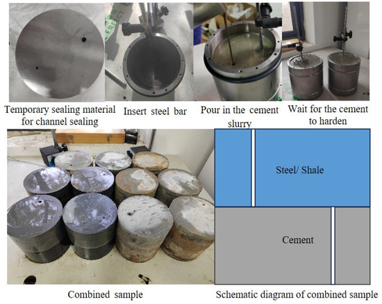
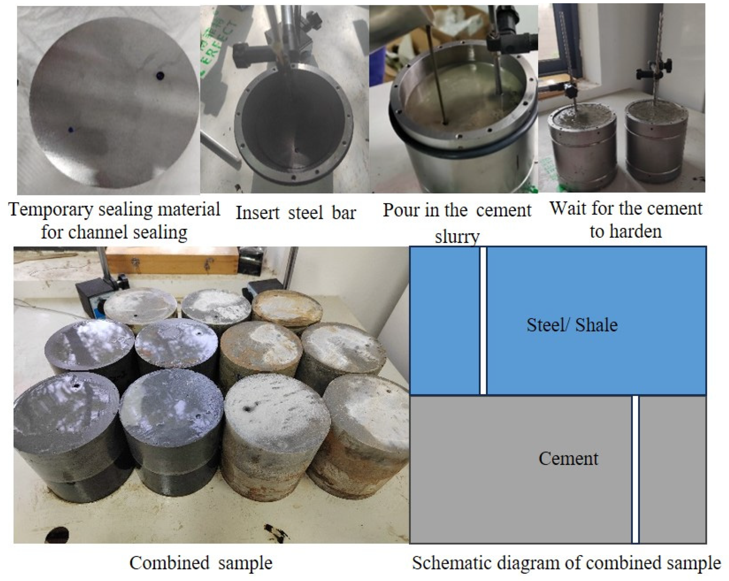
This study innovatively designed composite specimens capable of assessing interfacial airtightness. The specific procedure involved placing a steel/shale specimen with a diameter of 100 mm and a height of 50 mm into a custom mold. The steel/shale was prefabricated with a small through-hole, 25 mm from the edge. The hole was temporarily sealed with plugging material. Cement slurry was prepared according to the procedure in API 10B-2 [26], injected into the mold, and a steel rod was inserted opposite the through-hole to form a composite specimen with a centrally symmetrical through-hole, as shown in Figure 1. After the cement solidified, the steel rod was removed. Subsequently, the mold containing the cement slurry was subjected to high-temperature and high-pressure solidification and curing using a newly developed high-temperature and high-pressure curing apparatus to simulate the in situ downhole environment.
Figure 1.
Composite specimen preparation process.
Cement paste was cured at 140 °C, representing the formation temperature corresponding to burial depths of 3500 m. Since cement specimens exhibited rapid decay in compressive strength at 140 °C, silica fume was added to enhance their compressive strength. The curing pressure was fixed at 20 MPa, as it exerts no significant influence on compressive strength once it exceeds 3000 psi (20.7 MPa) [27]. Previous studies indicated that most cement slurry mixtures exhibit rapid strength development within 72 h during high-temperature curing [28,29]. Therefore, the curing duration for cement slurry under high-temperature and high-pressure conditions was set to 72 h in this study. Furthermore, it is essential to note that the temperature and pressure within the curing chamber were gradually increased or decreased over a 2 h period before and after the stable high-temperature, ultra-high-pressure pre-curing phase [30] to minimize potential damage to the cement paste specimens. Subsequently, the specimens were removed from the molds and placed in water tanks for 28 days of curing at ambient temperature. After curing, the cement portions of the specimens were cut and ground to a height of 50 mm, resulting in total specimen dimensions of 100 × 100 mm. Temporary plugging materials were crushed and removed to ensure unobstructed access to the specimens.
2.2. Test Equipment
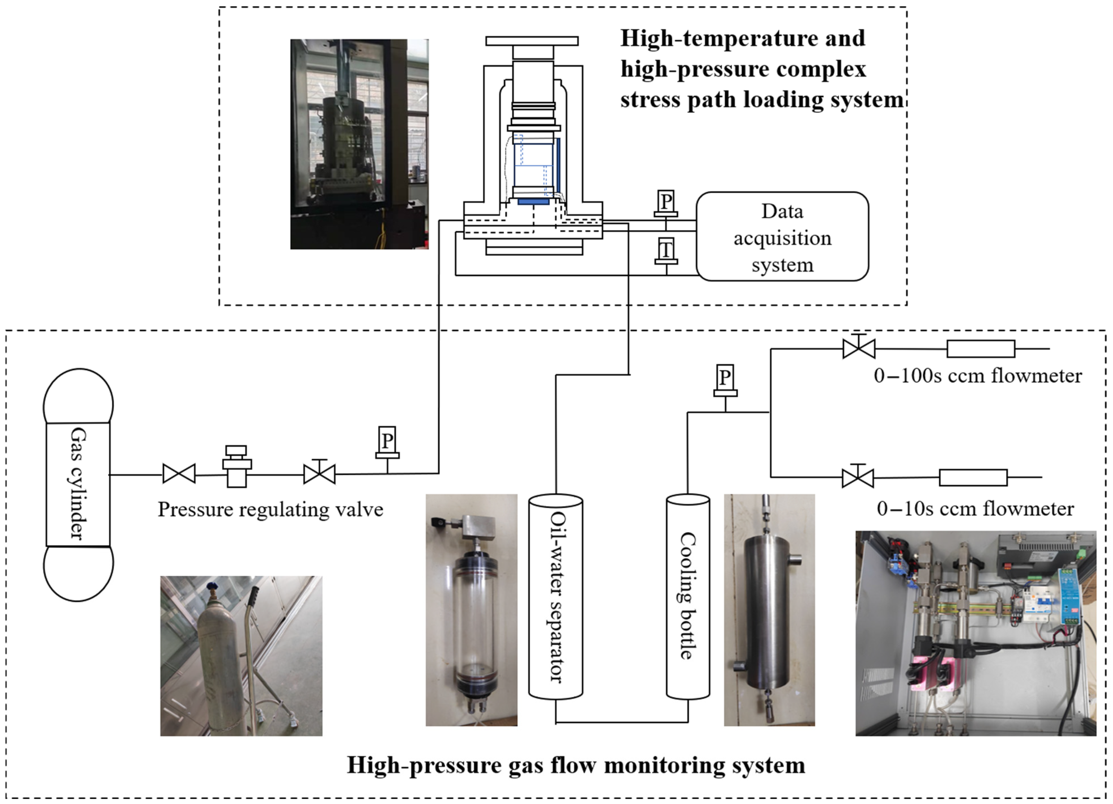
To enable testing of cementing interface integrity during cyclic loading and unloading processes, this study innovatively developed a sealing integrity testing system. The platform comprises two systems (Figure 2): first, a high-temperature and high-pressure complex stress path loading system capable of performing triaxial cyclic loading and unloading tests under high-temperature and high-pressure conditions; second, a high-pressure gas flow monitoring system for measuring gas flow rates at the interfaces of composite specimens during testing.
Figure 2.
Test equipment flowchart.
The High-Temperature Complex Stress Path Loading System, based on the high-temperature triaxial rock mechanics testing system, enables loading under high temperatures (150 °C), high confining pressures (50 MPa), and complex cyclic paths, with real-time acquisition of stress, strain, and other data. The system primarily comprises four components: force loading and displacement–strain control, stress–strain data acquisition, confining pressure control, and high-temperature heating control. The loading system within the triaxial chamber (including force transducers) and axial linear variable displacement transducers (LVDTs) ensures precise force application and deformation control. The confining pressure control system and high-temperature heating control system, respectively, deliver a controllable and accurate high-temperature, high-pressure testing condition.
The high-precision flow monitoring system comprises three components: gas flow metering, oil–water separation, and cooling. It enables real-time recording of downstream gas flow, preemptively separates any incidental oil ingress, and cools high-temperature gas to ensure the system’s normal operation. Equipped with one high-precision gas pressure regulator and two high-precision flow meters (ranging from 0 to 100 mL and 0 to 10 mL), the system continuously monitors and records the gas sealing performance of the cement and its interfaces. The upper and lower ends of the triaxial chamber are connected to the flow meters and gas cylinders, respectively. A pressure differential is established across the sample by injecting nitrogen upstream, while simultaneously monitoring the upstream and downstream gas pressure and flow rates in real time. An acrylic bottle is provided for oil separation. Additionally, a steel cylinder with a long, curved internal channel is included to increase the contact area between high-temperature gas and cooling water, enabling rapid temperature reduction. Seal failure was operationally defined based on the downstream flow signal. Specifically, a leakage event was deemed to occur when the recorded downstream gas flow rate exceeded the flow meter’s minimum detectable increment and persisted for at least three consecutive data points, thereby excluding transient fluctuations around the zero baseline.
Compared with previously reported high-temperature cyclic-loading integrity systems, the present setup provides innovations. It employs a compact composite specimen with a prefabricated symmetric leakage channel, allowing direct interrogation of interfacial sealing performance for both the first interface and the second interface under identical thermal–mechanical cycling protocols. These features allow simultaneous acquisition of stress–strain evolution and leakage flow responses during cyclic loading, facilitating mechanistic interpretation of interfacial seal degradation.
2.3. Test Scheme
To evaluate the interface sealing performance of the cement sheath under large-scale segmented hydraulic fracturing, this test was designed to consider the effects of temperature and cyclic loading on sample damage. Unlike conventional cyclic tests, displacement cycling was employed, which could more closely align with the actual stress and deformation characteristics of the cement sheath.
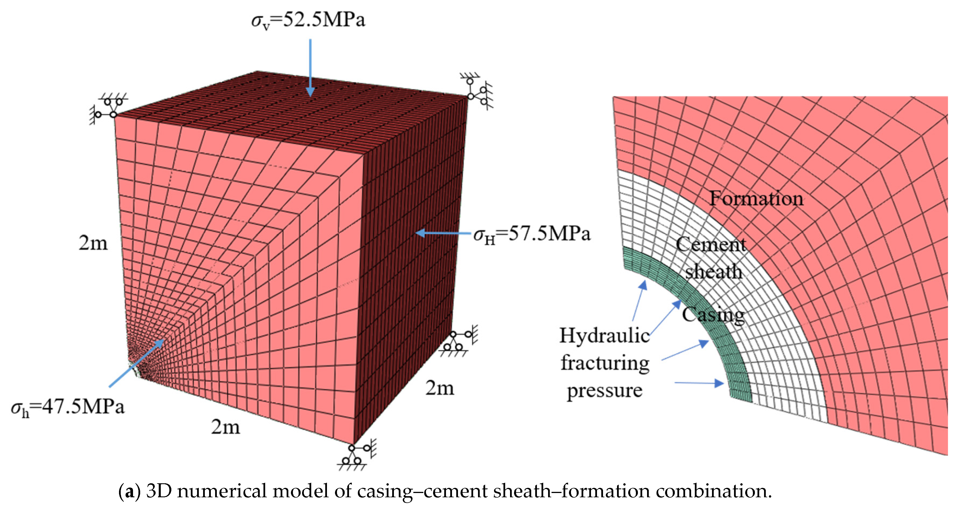
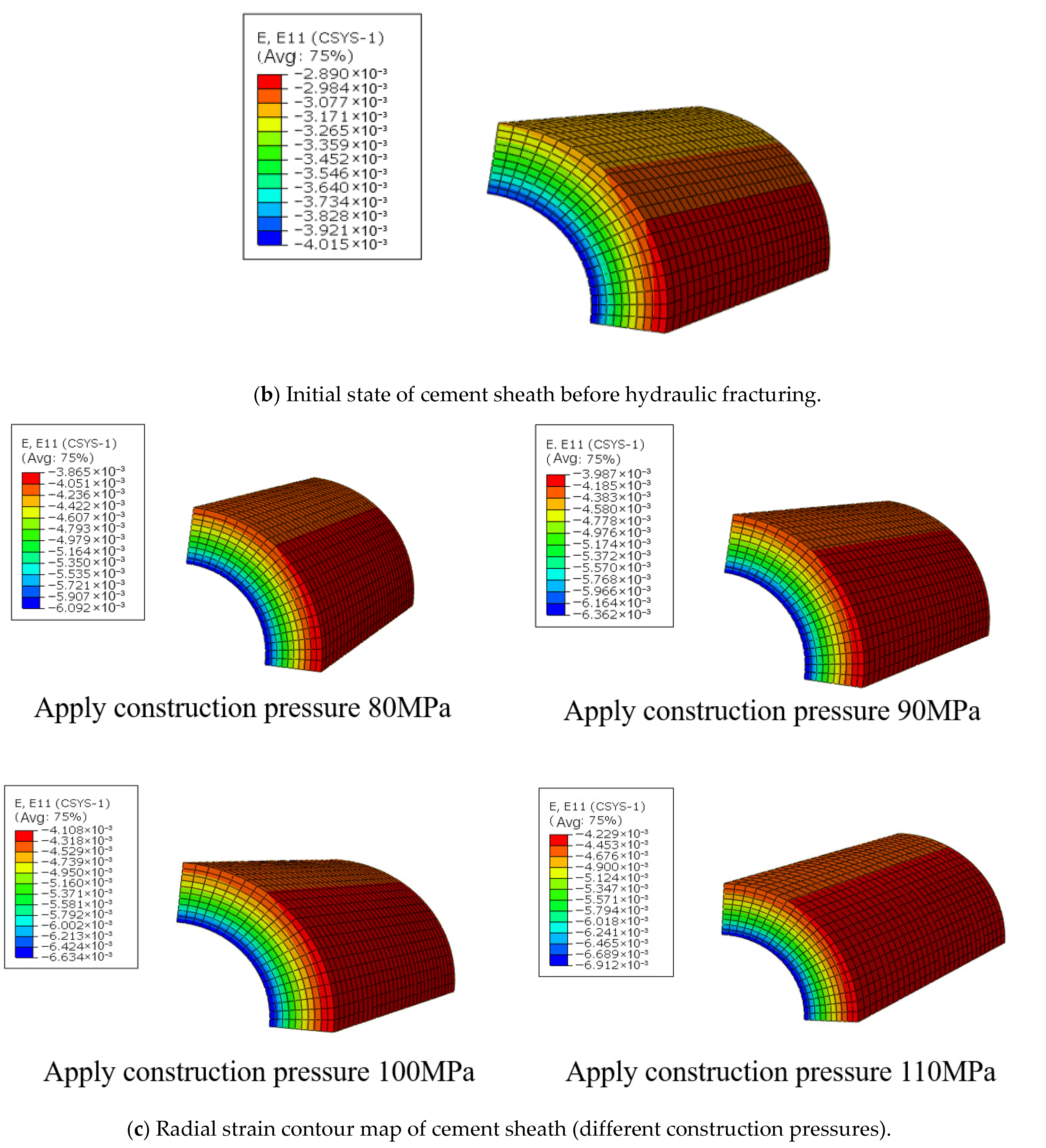
The experimental displacement values are determined by numerical simulation results at the engineering scale. Specifically, finite element calculations using ABAQUS were conducted with the following properties: The casing–cement sheath–formation system was established based on a typical shale gas horizontal well at a burial depth of 3500 m. The model dimensions were set to 2000 × 2000 × 2000 mm. The cement sheath had an outer diameter of 227 mm. The casing had an outer diameter of 139.7 mm and a wall thickness of 12.34 mm. The elastic modulus of shale formation was set at 20 GPa with a Poisson’s ratio of 0.2; the elastic modulus of cement was set at 5 GPa with a Poisson’s ratio of 0.2; and the elastic modulus of casing was set at 210 GPa with a Poisson’s ratio of 0.3. The vertical effective stress, horizontal maximum effective stress, and horizontal minimum effective stress were 52.5 MPa, 57.5 MPa, and 47.5 MPa, respectively. Additionally, “hard contact” was defined as the condition between bonded surfaces, allowing the cement to transfer normal compressive stress to the formation/casing but not tensile stress. Structured mesh generation was employed for the mesh. These simplifications neglect potential nonlinearity, progressive debonding, and sliding effects at the interface. Therefore, the numerical results are used in this study primarily to provide a rational basis for selecting representative engineering-scale displacement levels for the laboratory cyclic tests, rather than to predict absolute interfacial failure behavior.
The calculation results are shown in Figure 3. The strain values at the first and second interfaces of the cement sheath under the initial state before hydraulic fracturing were read, and the deformation value of the cement portion of the sample with a height of 50 mm was calculated using Equations (1) and (2):
L1 represents the deformation value of the cement portion at the first interface, and ε1 represents the strain value of the cement portion at the first interface; L2 represents the deformation value of the cement portion at the second interface, and ε2 represents the strain value of the cement portion at the second interface.
Figure 3.
Numerical model calculation.
Calculate the deformation value of the composite structure using Equations (3) and (4):
Here, LG denotes the deformation value of the cement–steel composite, while LY denotes the deformation value of the cement–shale composite. Potential sources of error include non-uniform interfacial strain fields and local stress concentrations in the field-scale model; 3D deformation effects not captured by the 1D series assumption, such as Poisson effects; and temperature- and curing-dependent uncertainty in elastic properties. Consequently, the converted displacement levels are intended to provide representative loading magnitudes for the cyclic tests rather than an exact, unique field-to-laboratory equivalence.
The deformation values of the composite structure under the applied construction pressure of hydraulic fracturing were calculated using the same method. The difference between the deformations before and after applying the construction pressure represents the cyclic displacement value in the test. Simulation results for applied construction pressures of 80, 90, 100, and 110 MPa are shown in Table 2.
Table 2.
Strain values of cement sheath at interfaces in engineering scale and deformation conversion to composite specimens.
In the test, the displacement-controlled load was applied cyclically to simulate the deformation conditions of various interfaces under different construction pressures. The damage and airtightness of the composite specimens were observed to evaluate the sealing performance of the cement sheath. Specimen code G denoted the cement/steel composite, corresponding to the first cementing interface, while Y denoted the cement/shale composite, corresponding to the second cementing interface. Previous studies indicated that cement sheath seal failure primarily occurs at the first interface [12,16]. Therefore, the experiments focused more on the cement–steel composite. The test design varied experimental temperatures (25, 90, 115, 140 °C) and multiple cyclic displacement levels (corresponding to upper limits of construction pressure of 80, 90, 100, 110 MPa). The specific test design is shown in Table 3.
Table 3.
Statistical summary of experimental design.
The specific steps include:
- (1)
- Before testing, insert the hollow steel tube into the sample hole and the custom-made indenter with channels. Wrap heat-shrink tubing to ensure gas does not escape around the sample and the internal channels remain unobstructed, thereby monitoring the seal integrity at the interface.
- (2)
- Place the sample into the triaxial chamber, connect the gas cylinder to the lower end and the gas flow monitoring device to the upper end, then immerse the cooling device in cold water.
- (3)
- Increase temperature and ambient pressure to predetermined values. Open the gas cylinder and adjust the inlet pressure to approximately 0.5 MPa.
- (4)
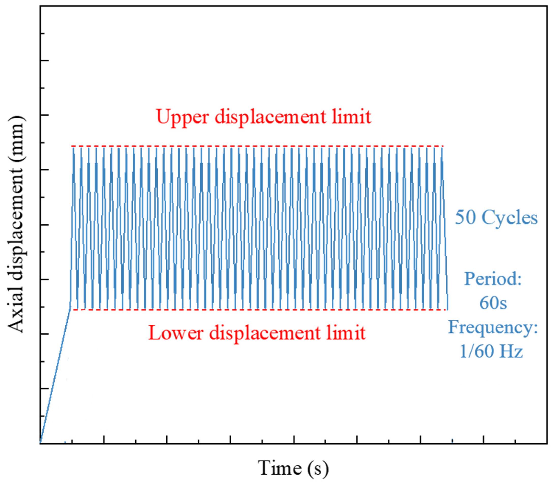
- Apply axial load at a rate of 0.2 MPa/s until reaching the lower displacement limit. Record this displacement value, set it as the lower limit for displacement cycling, and calculate the upper limit for displacement cycling.
- (5)
- For each sample, increase displacement from the lower limit to the set upper limit within one cycle. Complete 50 cycles of loading and unloading at a frequency of 0.01667 Hz. The displacement loading mode schematic is shown in Figure 4.
- (6)
- Observe and record the upstream gas pressure and downstream gas flow rate at the gas flow monitoring device.
Figure 4.
Schematic diagram of displacement-controlled path.
3. Results
3.1. Stress–Strain Curves
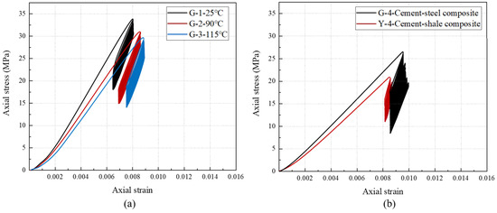
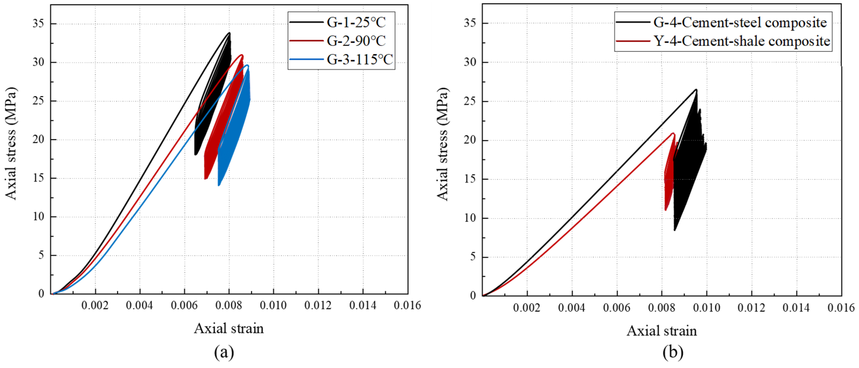
Figure 5 displays the stress–strain curves of cement–steel composite specimens and cement–shale composite specimens under varying temperatures and displacement magnitudes. During cyclic loading and unloading, the loading and unloading curves failed to coincide, forming hysteresis loops. As the number of cycles increased, the distribution of hysteresis loops evolved from sparse to dense. During the initial cycles, the abrupt stress increases rapidly and compacts the primary pores and microdefects within the specimens, causing significant irreversible deformation and resulting in a markedly large hysteresis loop area. As the number of cycles accumulates further, the deformation behavior of the rock specimens gradually enters a stable phase, manifested by more closely spaced stress–strain curves and increasingly consistent hysteresis loop morphology. At this point, the specimen’s deformation rate markedly slows, and the strain increment gradually stabilizes, indicating that its internal microstructure had undergone a phase of reorganization: initial pores and cracks were largely closed and compacted, while new microcracks continued to nucleate and propagate under cyclic loading. Together, these processes formed a dynamically balanced damage evolution mechanism.
Figure 5.
Stress–strain curve of the composite specimens: (a) at different temperatures and (b) under different compositions.
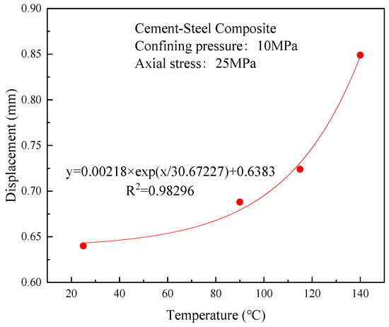
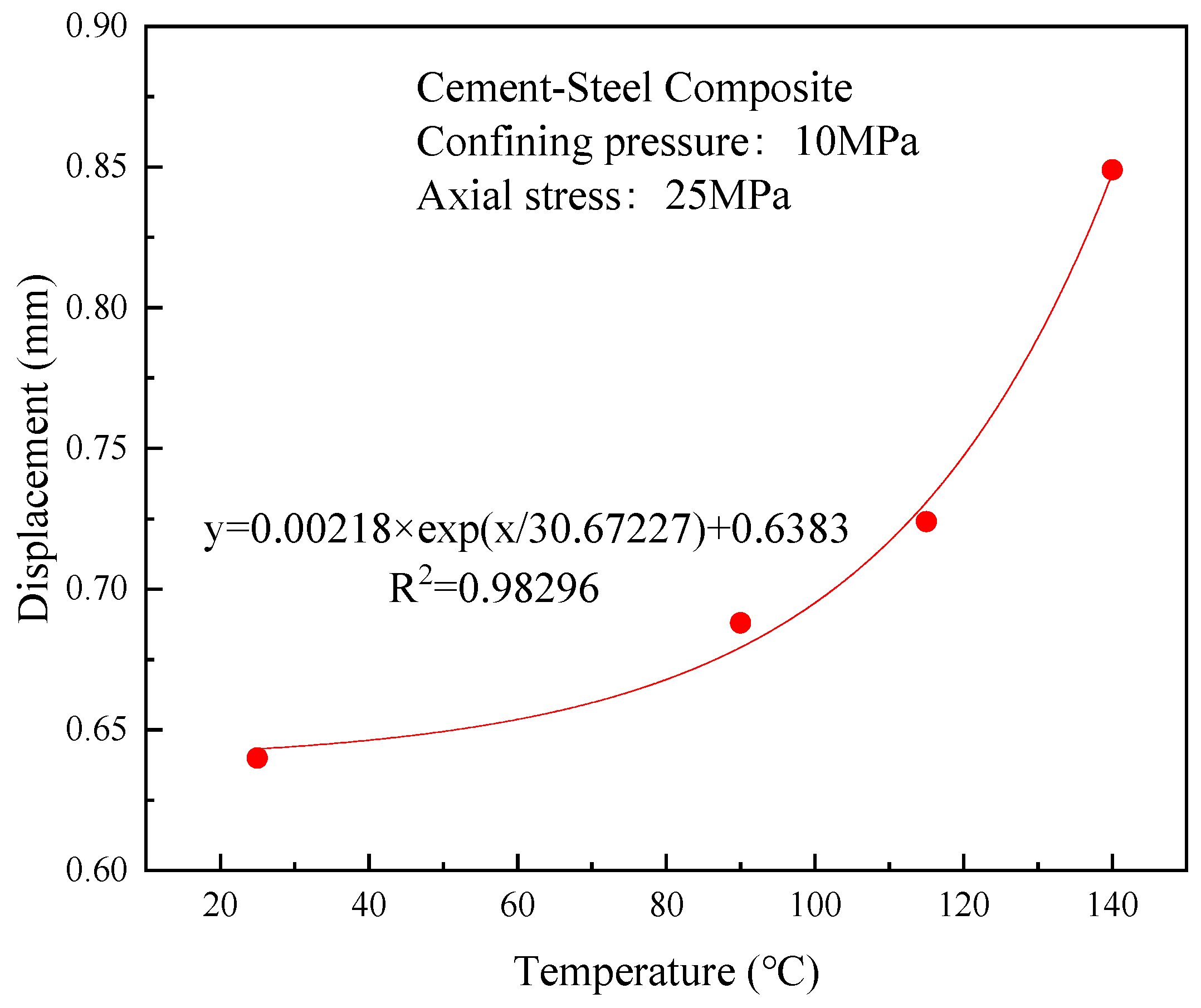
The displacement of the cement–steel composite under a confining pressure of 10 MPa and axial compression of 25 MPa at temperatures of 25, 90, 115, and 140 °C was 0.64, 0.688, 0.724, and 0.849 mm, respectively, as shown in Figure 6. As the test temperature increased, the composite exhibited greater deformation under identical pressure conditions, with deformation exhibiting an exponential relationship with temperature. This suggested that higher temperatures resulted in more severe damage and deterioration of the cementitious matrix’s microstructure.
Figure 6.
Displacement values of the cement–steel composite under identical pressure conditions.
Specimens G-4 and Y-4 underwent multistage displacement cycles, with each stage corresponding to operating conditions at maximum construction pressures of 80, 90, 100, and 110 MPa. As shown in Figure 5b, under identical operating conditions, the cement–steel composite experienced a greater force magnitude and amplitude of force variation compared to the cement–shale composite, indicating that the former interfaces withstood more extreme loads than the latter.
3.2. Interface Stress Analysis
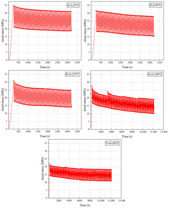
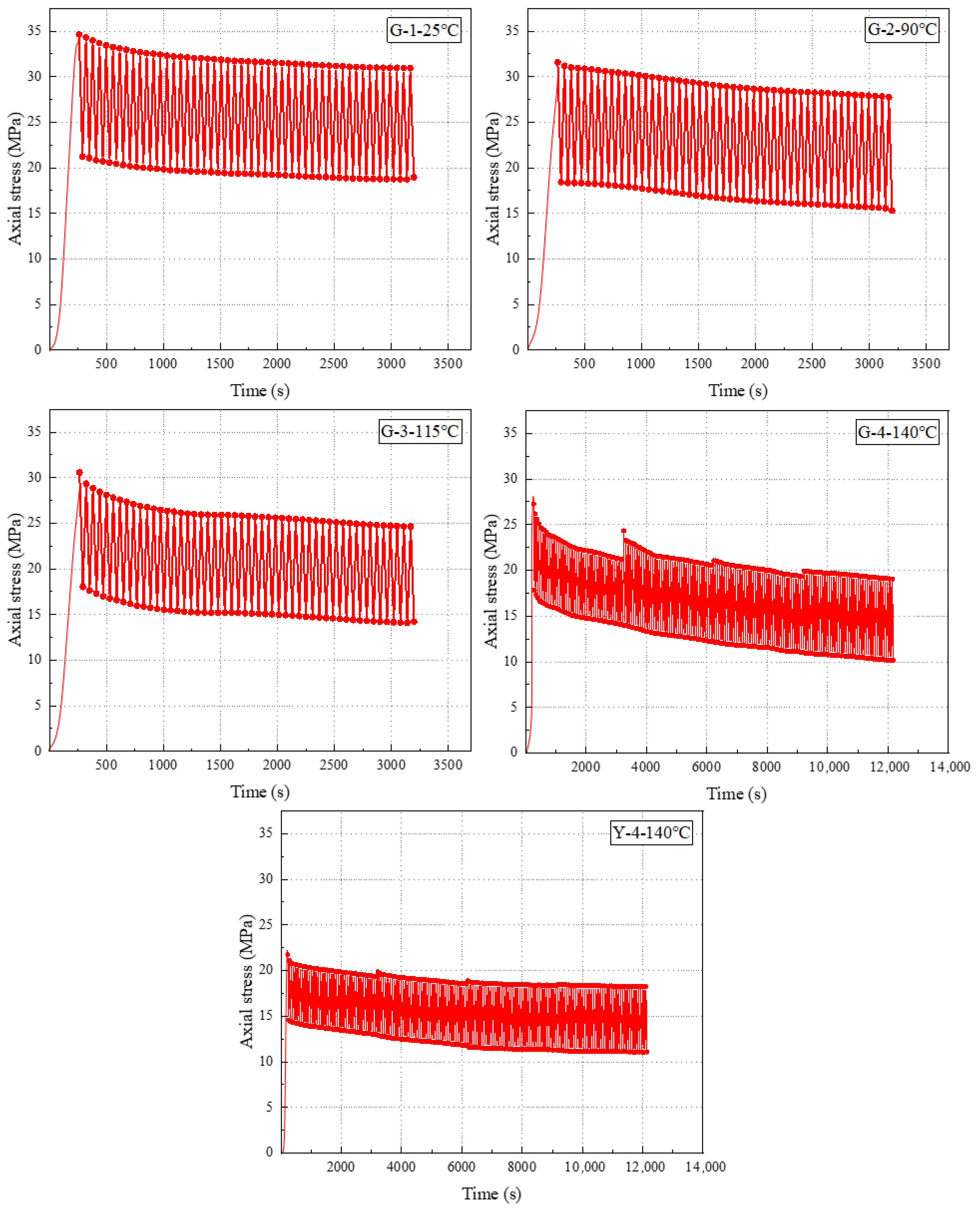
Under displacement control, the upper and lower stress limits per cycle were not constant, as shown in Figure 7. Data indicated that, as the number of cycles increased, the peak stress required to achieve the same displacement gradually decreased; that is, the interface normal stress was decreased. With further cycles, the decline in both upper and lower stress limits slowed down, eventually stabilizing at certain values. For G-4 and Y-4, the maximum and minimum axial stresses during the first cycle of the next deformation stage increased compared to the final cycle of the preceding stage. However, these values failed to exceed the maximum and minimum axial stresses observed during the first cycle of the preceding stage. For example, the maximum axial stress of G-4 during the first loading in the second level was 24.32 MPa. This value was greater than the 21.19 MPa recorded during the 50th cycle of the first level, but less than the 27.26 MPa observed during the first cycle of the first level. Moreover, the magnitude of this increase diminished progressively with each additional stage, reflecting the material’s softening and cumulative damage process. Despite elastic loading and unloading, each cycle resulted in minor, irreversible plastic residual deformation in the specimens. This deformation accumulated progressively with an increasing cycle count, constituting the fundamental cause for the generation and development of micro-gaps at the interface.
Figure 7.
Variation in axial stress in the composite specimens over time.
For the cement–steel composite specimens tested at temperatures of 25, 90, and 115 °C, the axial forces required to reach the upper displacement limit for the first time were 34.64, 31.59, and 30.58 MPa, respectively. As the temperature increased, the force required to achieve the same displacement value gradually decreased, indicating a negative impact of elevated temperatures on the composite’s mechanical properties.
Comparing specimens G-4 and Y-4, the maximum axial stress increased at each higher displacement level compared to the final cycle of the previous level. However, specimen G-4 exhibited greater sensitivity to displacement increases than specimen Y-4, indicating that each increase in the upper limit of construction pressure exerted a more pronounced effect on the first interface.
3.3. Interface Sealing Analysis
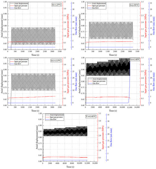
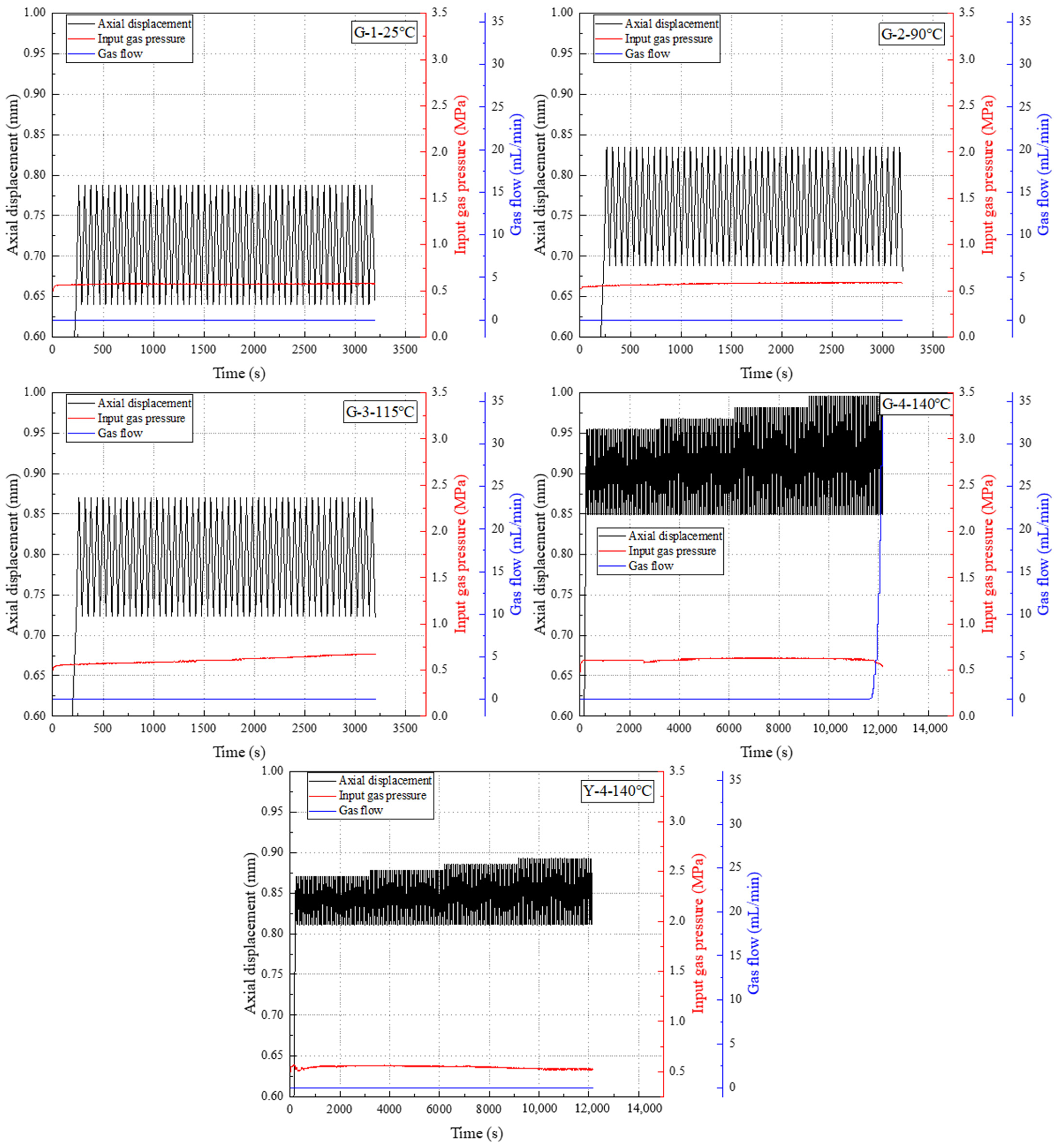
Figure 8 shows the changes in upstream gas pressure and downstream gas flow rate during the test of the composite structure. The critical point of the experiment was identified when the downstream gas flow rate first exceeded the flow meter’s minimum detectable increment and remained above this threshold for at least three consecutive data points. Initially, the gas flow may be extremely small and unstable, but as the cycle continued, the downstream gas flow increased rapidly and eventually stabilized at a higher value. This indicated that a permeable flow channel had formed across the interface, resulting in the complete loss of sealing integrity. At this point, upstream gas pressure may experience a slight decrease due to persistent gas leakage. Theoretically, as damage accumulated to a certain extent, the sealing capability of the interface began to deteriorate. The entire process clearly demonstrated the evolution path from “damage accumulation” to “sealing degradation” and ultimately to “macroscopic failure”. Test results indicated that G-4 exhibited increased downstream gas flow and decreased upstream gas pressure, confirming interface seal failure in this assembly. As shown in Figure 7 and Figure 8, the interface normal stress required for G-4 to return to its initial displacement value upon interface seal failure was 10.31 MPa. At this point, the damaged composite sample could not maintain interfacial sealing under low normal stress, leading to gas leakage.
Figure 8.
Gas monitoring at the interface of the composite specimens.
At test temperatures below 115 °C, neither the cement–steel composite nor the cement–shale composite exhibited gas leakage, indicating intact interfacial sealing. However, at 140 °C, downstream gas flow increased while upstream gas pressure decreased, resulting in interfacial sealing failure. This demonstrated that higher temperatures facilitate gas leakage and accelerate sealing failure.
The cement–steel composite G-4 exhibited gas leakage during the 41st displacement loading cycle at the fourth level, with interface normal stress decreasing to 10.31 MPa, while the cement–shale composite Y-4 remained intact. Both composites simulated changes in the first and the second interface sealing under identical conditions, revealing that the first interface was more susceptible to sealing failure.
To further quantify the leakage evolution shown in Figure 8, using the downstream flow meter records, we quantified the leakage rate evolution by reporting the leakage rate Q. An equivalent interfacial transmissivity was estimated to provide a comparable transport metric across conditions. The prefabricated through-holes serve as low-resistance injection conduits. Thus, the dominant pressure drop is assumed to occur along the connected interfacial leakage pathway after failure. The leakage path is idealized as a thin interfacial microchannel (microannulus) connecting the inlet and outlet ports. The effective interfacial path length Lint is taken as the center-to-center spacing between the two symmetric ports. Based on these measurements, we further estimated an equivalent interfacial transmissivity T using a Darcy-type relation (Equation (5)):
where R = 50 mm and Lint = 50 mm, ΔP is the measured inlet–outlet pressure differential, and μ is the gas viscosity. The calculated T values are on the order of 10−22–10−18 m2. We emphasize that this approach yields an equivalent metric for comparing leakage severity. Non-uniform aperture, tortuosity, gas compressibility, and possible slip effects are not explicitly captured.
4. Discussion
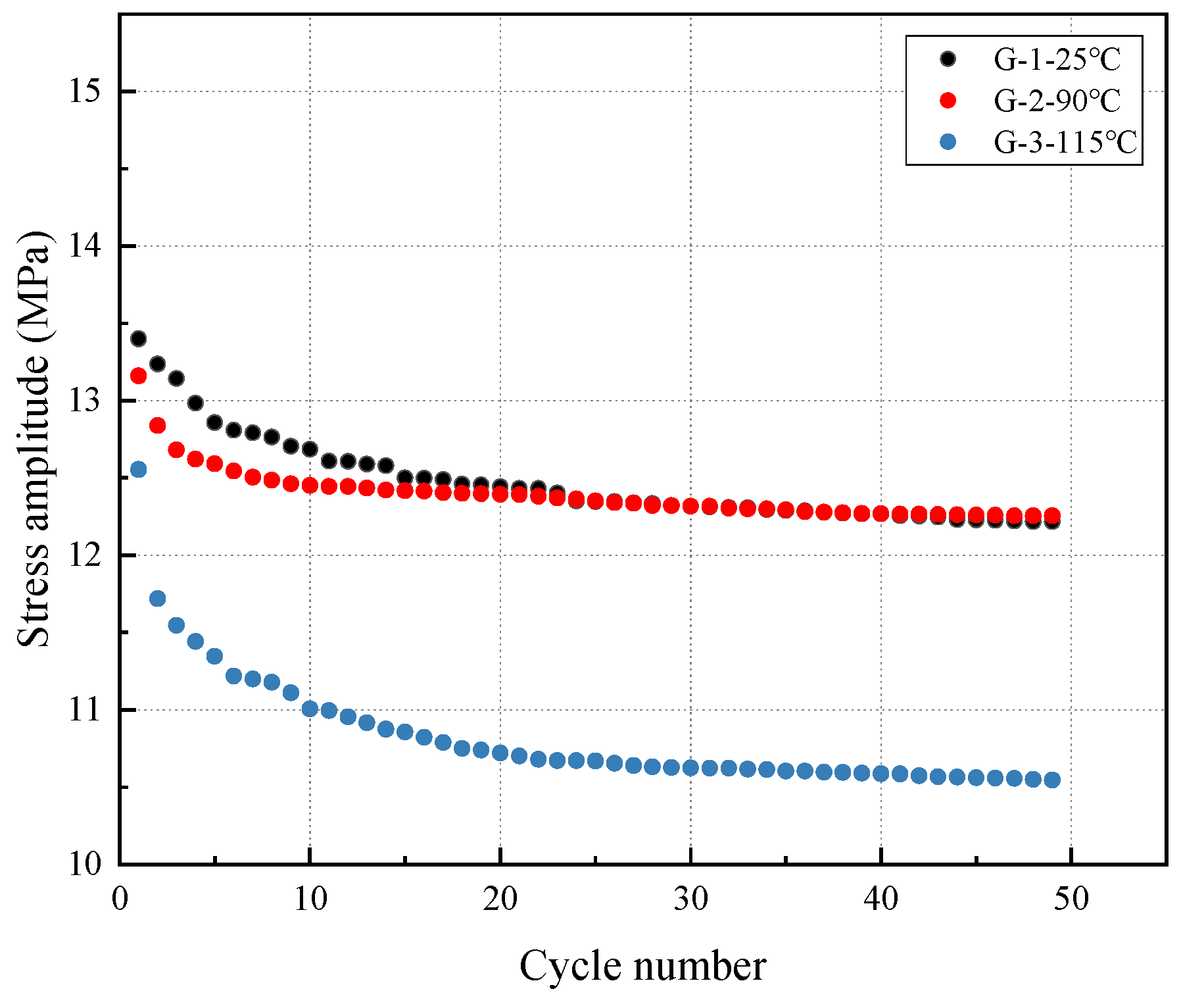
In cyclic loading tests with displacement control, the variation in stress amplitude (Δσ, i.e., the difference between the upper loading stress limit and the lower unloading stress limit) serves as a crucial indicator for evaluating a material’s fatigue performance. A decrease in stress amplitude directly reflects the accumulation of fatigue damage within the material.
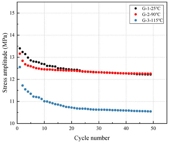
Table 4 shows the upper limit of loading stress σmax, lower limit of unloading stress σmin, and their difference Δσ for the first and last cycles of the composite structure. The results indicated that the stress amplitude Δσ decreased with increasing number of cycles (Figure 9). This phenomenon was known as stress relaxation or cyclic softening. During the initial stage of cyclic loading, the decline in Δσ was most pronounced. Subsequently, the rate of decrease slowed, and Δσ gradually stabilized at a plateau. This suggested that stresses within the material were redistributed and released during cycling, with a portion of elastic deformation converting into plastic deformation and damage.
Table 4.
Peak axial stress in composite displacement cycle test.
Figure 9.
Variation in stress amplitude with cycle number at different temperatures for cement–steel.
Comparing experimental results at different temperatures (Figure 9), the stress amplitude Δσ of G-1, G-2, and G-3 gradually decreased, leading to a clear conclusion: increased temperature significantly accelerated the damage accumulation process at the cement sheath interface. At higher temperatures, stress relaxation became more severe to achieve the same number of cycles. The temperature dependence of stress relaxation and leakage can be attributed to the thermally accelerated degradation of the cementitious matrix and enhanced thermal-mismatch strains at the interface. Elevated temperature can reduce stiffness and tensile resistance and promote microcrack initiation under cyclic deformation, while differential thermal expansion between the cement and casing facilitates progressive debonding and microannulus formation.
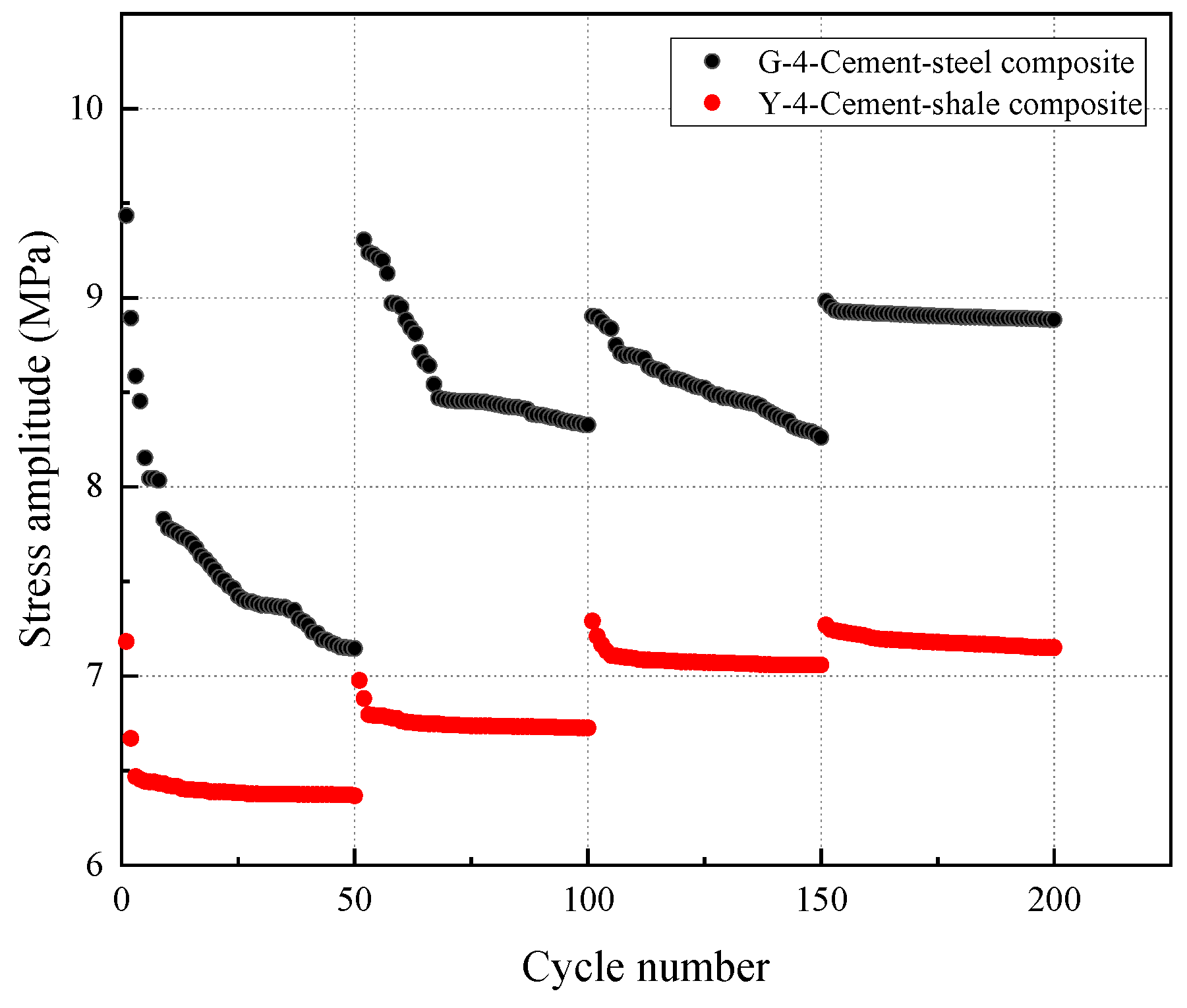
Apart from temperature, the level of cyclic displacement was also a critical parameter determining interface life. The experiments simulated different construction pressures, corresponding to varying levels of cyclic displacement. The stress amplitude variation in Y-4 (Figure 10) clearly demonstrated that larger cyclic displacements could accelerate the damage rate at the interface, thereby shortening seal life. Microcrack initiation and propagation occurred more rapidly. Consequently, in high-pressure fracturing operations, the risk of seal failure for the wellbore cement sheath increased dramatically.
Figure 10.
Variation in stress amplitude of cement–steel and cement–shale composite under different displacement levels during cycling.
By comparing data from cement–steel assemblies and cement–shale assemblies, differences in stress relaxation behavior were observed. For cement–steel assemblies, the reduction in stress amplitude at each stress level (the difference between the stress amplitude during the first loading of the first level and the first loading of each level) ranged from 0.01 to 0.24 times the initial amplitude (stress amplitude during the first loading of the first level), while the cement–shale composite exhibited a reduction in stress amplitude ranging from 0.007 to 0.11 times the initial amplitude, significantly lower than that of the cement–steel composite. These results suggest a plausible interfacial mechanism: the relatively smooth steel surface could provide weaker physical bonding and mechanical interlocking with cement, whereas the rough and porous shale surface may promote stronger cementation and mechanical interlock. Therefore, under identical cyclic loading conditions, stress relaxation at the first interface (cement–steel) may be more pronounced, leading to faster damage accumulation and increased susceptibility to slip and debonding at the interface. This aligns with the widely accepted notion that “the first interface is more prone to seal failure.”
Based on the above analysis and discussion, our experimental results systematically and quantitatively revealed the influence patterns of temperature and cyclic loading (stress level and number of cycles) on the mechanical behavior, damage evolution, and sealing performance of the first and second interfaces in cement sheath.
Since the first interface exhibited greater vulnerability than the second interface under thermo-mechanical cycling, the results suggest that cementing design should prioritize strengthening the first interface. Surface sandblasting and grooving of the casing can enhance mechanical interlocking and friction resistance. Alternatively, adding fiber modifiers improves crack resistance, or using shrinkage inhibitors or micro-expansion agents reduces micro-ring gap formation.
A limitation of this study is that replicate specimens under identical temperature–displacement conditions were not included. The test results are consistent with existing experience, thus demonstrating a certain degree of reliability [12,19,20]. Future work will incorporate replicate specimens to quantify the inter-specimen variability of cement-based interfacial sealing performance.
5. Conclusions
This study developed a sealing integrity testing system and evaluation method capable of simulating complex downhole conditions and enabling the real-time monitoring of mechanical seepage responses. Through physical simulation experiments, the sealing performance of the first interface (cement–steel) and the second interface (cement–shale) within the cement sheath was thoroughly evaluated under simulated temperature–pressure cyclic loading conditions typical of shale gas wells. The key conclusions are as follows:
- (1)
- The seal integrity testing system effectively controls the temperature and strain paths while monitoring leakage at cement sheath interfaces. The design and fabrication of the cement sheath assembly achieve the intended experimental outcomes, enabling future application in engineering fields such as gas storage reservoirs and hydrogen storage facilities.
- (2)
- As the number of cycles increases, the peak stress required to achieve the same displacement gradually decreases, while the downward trends in the upper and lower stress limits slow, eventually stabilizing at certain stress values. Minor, irreversible plastic residual deformation accumulates with increasing cycles, constituting the fundamental cause of micro-ring gap formation and development at the interface.
- (3)
- As the test temperature increases, the composite exhibits greater deformation under identical pressure conditions, with deformation showing an exponential relationship to temperature. This indicates that higher temperatures accelerate damage and degradation within the cement microstructure. At temperatures below 115 °C, neither the cement–shale nor the cement–steel composite exhibited gas leakage, maintaining intact interfacial sealing integrity. However, at 140 °C, interfacial sealing failure occurred in cement–steel composite.
- (4)
- Greater cyclic displacement accelerates interface damage rates, shortens seal lifespan, and hastens microcrack initiation and propagation. During high-pressure fracturing operations, the risk of seal failure in the wellbore cement sheath increases dramatically.
- (5)
- The hydraulic fracturing pressure has a more pronounced effect on the first interface. The cement–steel composite G-4 exhibited gas leakage during the 41st displacement loading cycle at the fourth level, with interface normal stress decreasing to 10.31 MPa, while the cement–shale composite Y-4 always remained intact. This indicates that, under identical operating conditions, the first interface is more susceptible to seal failure.
Author Contributions
Methodology, Y.J.; software, C.S.; formal analysis, Q.Y. and Z.B.; data curation, Q.Y. and C.S.; writing—original draft preparation, Q.Y.; writing—review and editing, L.W.; supervision, Y.G.; project administration, Y.G.; funding acquisition, Y.G., L.W. and Z.B. All authors have read and agreed to the published version of the manuscript.
Funding
This work was funded by “National Natural Science Foundation of China” (Nos. 52474085, U22B6003), “Key Laboratory of Geomechanics and Geotechnical Engineering Safety, Chinese Academy of Sciences” (Grant No. SKLGME-JBGS2404), “Frontier Technology Research and Development Program of Jiangsu Province” (No. BF2024056), and “Natural Science Foundation of Wuhan” (No. 2024040701010062). “Science Foundation of China University of Petroleum, Beijing” (No. 2462025XKBH029).
Data Availability Statement
Data will be made available on request.
Conflicts of Interest
The authors declare that they have no known competing financial interests or personal relationships that could have appeared to influence the work reported in this paper.
References
- Hou, M.; Ge, S.; Cheng, X. China’s energy security under the new situation: Connotation, challenges and strategic initiatives. Nat. Gas Ind. 2022, 42, 157–165. [Google Scholar]
- Ma, X.H.; Wang, H.; Zhou, S.; Shi, Z.; Zhang, L. Deep shale gas in China: Geological characteristics and development strategies. Energy Rep. 2021, 7, 1903–1914. [Google Scholar] [CrossRef] [Scilit]
- Karakosta, E.; Lagkaditi, L.; ElHardalo, S.; Biotaki, A.; Kelessidis, V.; Fardis, M.; Papavassiliou, G. Pore structure evolution and strength development of G-type elastic oil well cement. A combined 1H NMR and ultrasonic study. Cem. Concr. Res. 2015, 72, 90–97. [Google Scholar] [CrossRef] [Scilit]
- Pang, X.Y.; Qin, J.; Sun, L.; Zhang, G.; Wang, H. Long-term strength retrogression of silica-enriched oil well cement: A comprehensive multi-approach analysis. Cem. Concr. Res. 2021, 144, 15. [Google Scholar] [CrossRef] [Scilit]
- Zhao, G.K.; Guo, Y.; Wang, L.; Chang, X.; Yang, H.; Guo, W.; Wu, X.; Yang, C. Experimental Study on Mechanical, Brittleness, and Fracture Behavior of Deep Shales Subjected to Fracturing Fluid-Shale Interactions at Reservoir Temperature and In-Situ Stress Conditions. Rock Mech. Rock Eng. 2023, 18, 27–44. [Google Scholar] [CrossRef] [Scilit]
- Yuan, Z.; Gardoni, P.; Schubert, J.; Teodoriu, C. Cement failure probability analysis in water injection well. J. Pet. Sci. Eng. 2013, 107, 45–49. [Google Scholar] [CrossRef] [Scilit]
- Lian, W.; Li, J.; Tao, Q.; Liu, G.; Wang, W.; Ren, K. Sealing Failure Mechanism and Control Method for Cement Sheath during Hydraulic Fracturing. ACS Omega 2020, 5, 19978–19994. [Google Scholar] [CrossRef] [Scilit]
- Wu, X.N.; Li, Z.; Hou, Z.; Liu, J.; Huang, S.; Su, D.; Li, J.; Cao, C.; Wu, L.; Song, W. Analytical Perspectives on Cement Sheath Integrity: A Comprehensive Review of Theoretical Research. ACS Omega 2024, 9, 17741–17759. [Google Scholar] [CrossRef] [Scilit]
- Su, D.H.; Huang, S.; Li, Z.; Li, J.; Wu, X.; Tang, S.; Li, X. Theoretical study on the hydraulic sealing integrity of cement sheath in horizontal shale oil wells under fracturing: Crack propagation mode and mechanism. Adv. Mech. Eng. 2022, 14, 20. [Google Scholar] [CrossRef] [Scilit]
- Zhao, Z.H.; Li, M.; Zhang, Z.; Liu, G.; Zhou, P.; Guo, C.; Liu, S. Experimental study on the factors affecting cement bond strength at the second interface of oil-gas well. J. Dispers. Sci. Technol. 2024, 11, 649–659. [Google Scholar] [CrossRef] [Scilit]
- Gu, J.; Gao, X.; Liu, H. Two-interface isolation system of oil/gas well cementing and its damage model. Nat. Gas Ind. 2006, 26, 74–76. [Google Scholar]
- Wu, J.W.; Wang, X.; Xie, S.; Wu, Y.; Li, Y.; Shu, Z.; Zhang, X.; Lian, W.; Yuan, D. A Study on the Crack Propagation Behavior of Cement Sheath Interfaces Considering Bond Strength. Processes 2025, 13, 1631. [Google Scholar] [CrossRef] [Scilit]
- Yang, Y.; Fang, Z.; Yuan, B.; Xie, Y.; Yan, S. Integrity Evaluation of the First Interface of Cement Sheath Based on Tensile Bonding Strength. J. Southwest Pet. Univ. Sci. Technol. Ed. 2021, 43, 183–190. [Google Scholar]
- Zheng, S.; Cheng, L. Integrity evaluation method for cement sheath of hydraulic fracturing wells. Arab. J. Geosci. 2022, 15, 1283. [Google Scholar] [CrossRef] [Scilit]
- Wang, Y.A.; Feng, Y.C. Experimental and Numerical Simulation Investigation of Cement Sheath Integrity during Multi-Stage Fracturing in Offshore Tight Oil Reservoir. J. Mar. Sci. Eng. 2024, 12, 814. [Google Scholar] [CrossRef] [Scilit]
- Cheng, Y.; Liu, S.; Shen, J.; Guo, X.; Huang, Z.; Liu, H. Matching analysis and experimental study of mechanical properties of cement sheath interface. Geoenergy Sci. Eng. 2023, 220, 111138. [Google Scholar] [CrossRef] [Scilit]
- Guan, Z.; Deng, K.; Wu, Y.; Lin, Z.; Lin, Y. Experimental Evaluation on the Cement Sheath Integrity of Unconventional Oil and Gas Well During Large-scale Hydraulic Fracturing. J. Southwest Pet. Univ. Sci. Technol. Ed. 2023, 45, 121–132. [Google Scholar]
- Hou, D.; Zhang, Z.; Geng, Y.; Wu, Z.; Yang, H. Experimental study on the channeling leakage properties of compact-size casing-cement sheath-stratum assembly in deep and ultra-deep wells. Process Saf. Environ. Prot. 2023, 178, 881–892. [Google Scholar] [CrossRef] [Scilit]
- Shadravan, A.; Schubert, J.; Amani, M.; Teodoriu, C. Using Fatigue-Failure Envelope for Cement-Sheath-Integrity Evaluation. SPE Drill. Complet. 2015, 30, 68–75. [Google Scholar] [CrossRef] [Scilit]
- Deng, K.H.; Yuan, Y.; Hao, Y.; Li, Z.; Lin, Y. Experimental study on the integrity of casing-cement sheath in shale gas wells under pressure and temperature cycle loading. J. Pet. Sci. Eng. 2020, 195, 11. [Google Scholar] [CrossRef] [Scilit]
- Zhou, S.M.; Liu, K.; Ding, S.; Liu, R.; Han, Q.; Shen, Z. Study on the mechanism and controlling method for annulus pressure buildup problems in shale gas wells. Geoenergy Sci. Eng. 2023, 228, 212065. [Google Scholar] [CrossRef] [Scilit]
- Zhou, B.; Liu, Z.; Zhang, B.; Cao, L.; Li, Y.; Deng, J.; Jiang, R. Study on the distribution law of casing external load in deep wells considering the cementing quality damage. Chem. Technol. Fuels Oils 2023, 58, 1046–1052. [Google Scholar] [CrossRef] [Scilit]
- Li, J.; Xi, Y.; Tao, Q.; Li, Y.; Qu, G. Experimental investigation and numerical simulation of the emergence and development of micro-annulus in shale gas wells subjected to multistage fracturing. J. Nat. Gas Sci. Eng. 2020, 78, 15. [Google Scholar] [CrossRef] [Scilit]
- Han, X.; Feng, F.; Zhang, J. Study on the whole life cycle integrity of cement interface in heavy oil thermal recovery well under circulating high temperature condition. Energy 2023, 278, 127873. [Google Scholar] [CrossRef] [Scilit]
- Gholami, R.; Aadnoy, B.; Fakhari, N. A thermo-poroelastic analytical approach to evaluate cement sheath integrity in deep vertical wells. J. Pet. Sci. Eng. 2016, 147, 536–546. [Google Scholar] [CrossRef] [Scilit]
- API RP 10B-2; 10B-2: Recommended Practice for Testing Well Cements. American Petroleum Institute: New York, NY, USA, 2013.
- Liu, H.T.; Qin, J.; Zhou, B.; Liu, Z.; Yuan, Z.; Zhang, Z.; Ai, Z.; Pang, X.; Liu, X. Effects of Curing Pressure on the Long-Term Strength Retrogression of Oil Well Cement Cured under 200 °C. Energies 2022, 15, 6071. [Google Scholar] [CrossRef] [Scilit]
- Choolaei, M.; Rashidi, A.M.; Ardjmand, M.; Yadegari, A.; Soltanian, H. The effect of nanosilica on the physical properties of oil well cement. Mater. Sci. Eng. A-Struct. Mater. Prop. Microstruct. Process. 2012, 538, 288–294. [Google Scholar] [CrossRef] [Scilit]
- Tariq, Z.; Murtaza, M.; Mahmoud, M. Effects of Nanoclay and Silica Flour on the Mechanical Properties of Class G Cement. ACS Omega 2020, 5, 11643–11654. [Google Scholar] [CrossRef] [Scilit]
- Jimenez, W.C.; Darbe, R.; Pang, X. Enhanced Mechanical-Integrity Characterization of Oilwell Annular Sealants Under In-Situ Downhole Conditions. SPE J. 2019, 24, 2308–2319. [Google Scholar] [CrossRef] [Scilit]

Disclaimer/Publisher’s Note: The statements, opinions and data contained in all publications are solely those of the individual author(s) and contributor(s) and not of MDPI and/or the editor(s). MDPI and/or the editor(s) disclaim responsibility for any injury to people or property resulting from any ideas, methods, instructions or products referred to in the content. |
© 2026 by the authors. Licensee MDPI, Basel, Switzerland. This article is an open access article distributed under the terms and conditions of the Creative Commons Attribution (CC BY) license.