


Abstract
Conventional mixed-flow pump designs are typically developed under the assumption of uniform inflow. However, due to various operational constraints, these pumps often operate under non-uniform inflow conditions, which can significantly deteriorate hydraulic performance and operational stability. To investigate the influence of inflow conditions on parameter analysis and optimization results of mixed-flow pumps, this study conducted optimization design under both uniform and non-uniform inflow conditions. Four loading control parameters—LE (leading-edge preloading), K (slope of the intermediate linear segment), and NC and ND (first and second loading inflection positions)—were selected as design parameters, while the weighted hydraulic efficiency at 0.8Qdes, 1.0Qdes, and 1.2Qdes served as the optimization objective. Under uniform inflow conditions, the sensitivity ranking of the parameters for efficiency (subscripts s and h denote shroud and hub, respectively) is: LEs > Kh > LEh > NDh > NCh > Ks > NCs > NDs. The corresponding optimal parameter values are −0.2, 0, 0.2, 0.4, 0.25, 1.5, 0.1, and 0.6. Under non-uniform inflow, the ranking changes markedly to: NCh > LEs > Kh > Ks > NDh> LEh > NDs > NCs, with optimal values of 0.4, 0, 1.5, 0, 0.6, −0.2, 0.8, and 0.1, respectively. Compared with the baseline model, the optimized configurations achieve efficiency improvements of 0.61%, 2.94%, and 3.74% under uniform inflow, and 0.23%, 4.42%, and 6.78% under non-uniform inflow. Analysis of the internal flow field indicates that incorporating inflow conditions at the initial design stage significantly enhances the robustness of the optimized blade geometry when subjected to non-uniform inflow. These findings provide important implications for the optimization and practical design of mixed-flow pumps operating under complex inflow environments.
1. Introduction
Mixed-flow pumps are widely employed in industrial processes, agricultural irrigation, and deep-sea propulsion owing to their capability to deliver high flow rates with moderate heads [1]. Positioned structurally between axial-flow and centrifugal pumps, mixed-flow pumps exhibit complex internal flow characteristics due to the combined effects of axial and radial forces [2]. Consequently, research on design optimization to enhance their overall performance is essential.
Numerous researchers have conducted studies on the design optimization of mixed-flow pumps. Wang et al. [3,4] compared the effects of different vortex design schemes on multi-condition optimization outcomes for mixed-flow pumps and demonstrated that composite vortex designs outperform free-vortex designs. Heo et al. [5] enhanced the efficiency of a mixed-flow pump by coupling a surrogate model with an optimization algorithm while maintaining a constant specific speed. Kim et al. [6] conducted a systematic investigation into the effects of impeller geometry and specific speed on the suction performance and efficiency of mixed-flow pumps. Li et al. [7] employed quasi-steady-state theory to optimize vortex-induced energy losses during pump startup, effectively enhancing transient head in the latter stages of startup and hydraulic efficiency during the mid-startup phase. Based on parameter analysis, Ding et al. [8] applied a multi-objective optimization algorithm to optimize a mixed-flow pump across multiple operating conditions, successfully expanding its high-efficiency range. Sun et al. [9] optimized a high-specific-speed mixed-flow pump by adjusting the position of the maximum camber in the airfoil profile. He [10] performed multi-objective optimization on the energy characteristics and cavitation performance of mixed-flow pumps.
Although these studies have achieved notable progress, they share a common assumption—uniform inflow at the impeller inlet. However, in practical applications, pump inlets often experience non-uniform inflow [11]. Non-uniform inflow can easily lead to problems such as asymmetric radial load and angle of attack mismatch at the leading edge of the blade, which in turn leads to problems such as reduced efficiency, increased vibration, and local low pressure. Several researchers have investigated the effects of non-uniform inflow on pump performance. Zheng et al. [12,13] examined how variations in inflow angle influence the hydrodynamic characteristics of pump systems under non-uniform inflow. Their results showed that pulsation intensity under non-uniform inflow was significantly higher than that under uniform inflow and increased with the inflow angle. Similarly, Yao [14] investigated the unsteady excitation characteristics induced by inflow distortion in centrifugal pumps, while Drǎghici et al. [15] measured its influence on the performance of pumped storage units using the Laser Doppler velocimeter (LDV) technique. Li et al. [16] studied the influence of non-uniform inflow on nuclear main pumps and axial-flow pumps. To improve pump performance under such conditions, Esch [17] experimentally investigated the evolution of internal flow states in a centrifugal pump subjected to distorted inflow, whereas Cao et al. [18] conducted targeted research on the performance response of pump nozzles under distorted flow. Quan et al. [19] noted that under certain conditions, distorted inflow can easily cause gas blockage failure in multiphase mixed-transport pumps.
In summary, non-uniform inflow is known to deteriorate pump performance and aggravate flow instability. However, research on the design optimization of pumps under such conditions remains limited, particularly regarding the influence of inflow conditions on parametric analysis and optimization sensitivity. To address this gap, the present study employs a coupled orthogonal test–inverse design method. Using hub and shroud loading-control parameters as design parameters and the weighted efficiencies at 0.8Qdes, 1.0Qdes, and 1.2Qdes as optimization objectives, a comprehensive parametric analysis and design optimization are carried out for a medium-specific-speed mixed-flow pump under both uniform and non-uniform inflow conditions.
2. Inverse Design Method
This paper employs the inverse design method proposed by Zangeneh [20] to parameterize the blade’s geometry (Turbodesign 6.4.0). In this method, the working fluid is assumed to be inviscid, and the blade is treated as having zero thickness. The effect of the blade on the fluid is replaced by the vortex, and the strength is calculated from the circumferential average velocity moment :
where Vθ denotes the circumferential average velocity, B denotes the number of blades, and r denotes the radius.
Under the above assumptions, according to the incompressible potential flow theory [21], the pressure difference Δp across the blade surface and the derivative of the circumferential mean velocity moment along the streamline are related as follows:
where p+ and p− denote the static pressure on the pressure side and suction side of the blade, respectively; Wm denotes the pitch-wise averaged meridional velocity; and m denotes the normalized streamline.
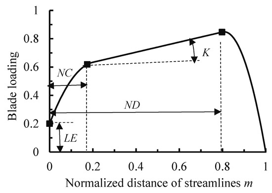
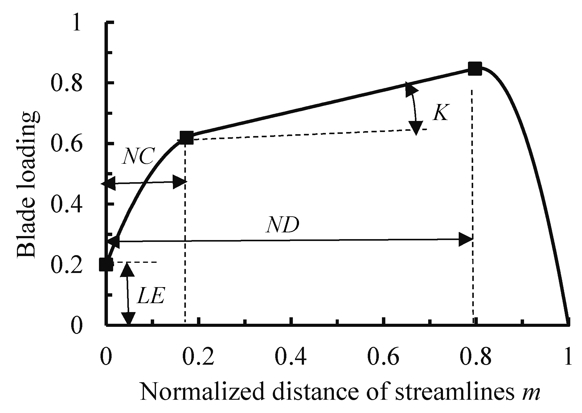
From Equation (2), it is evident that rational control of the distribution of across the blade surface enables effective regulation of surface pressure. To effectively control the blade loading distribution, this study employs a classical three-segment loading curve, as illustrated in Figure 1, to prescribe the hub and shroud loading distribution. Wang Peng [22] pointed out that the three-segment loading curve has the advantages of controllability and style variability compared with other single high-order curves, and is more suitable for the design optimization of turbomachinery under complex working conditions. The loading at the rest of the blade surface is determined by linear interpolation. It should be noted that under distorted inflow conditions, there may be more excellent loading distribution forms, but to maintain consistency and reduce the amount of calculation in this study, linear interpolation is adopted under both inflow conditions. In the figure, LE is the preloading value at the leading edge, which is directly related to the angle of attack; NC represents the first loading point, being the x-coordinate of the intersection between the first parabolic segment and the intermediate straight line; ND denotes the second loading point, being the x-coordinate of the intersection between the intermediate straight line and the second parabolic segment; and K is the slope of the intermediate straight line, which is directly related to the pressure gradient. An appropriate combination of LE, NC, ND, and K values can effectively suppress secondary flow.
Figure 1.
Schematic diagram of three-segment curve distribution.
Specifically, due to the difference between the assumptions used in the inverse design method and the real situation, computational fluid dynamics must be employed to evaluate the performance of the designed pump. The computational setup and validation are detailed in Chapter 3.
3. Numerical Simulation Setup and Validation
3.1. Calculation Settings
All computations were performed using ANSYS-CFX 2019 R3. The Shear Stress Transport (SST) k-ω turbulence model was adopted due to its proven capability in predicting flow separation in pumps [23,24]. All walls were modeled as smooth with no-slip boundary conditions using wall functions. The impeller was treated as a rotating domain operating at 1450 rpm, whereas the remaining components were modeled as stationary domains. A mixing plane interface was employed to couple the rotating and stationary domains, and standard interfaces were applied between the stationary domains. The maximum number of iterations was set to 1000, and the residual convergence criterion was set to 10−5. The impeller outlet was specified as a pressure-outlet boundary condition with a reference static pressure of 1 atm to permit controlled backflow. The inlet was defined as a velocity-inlet boundary condition with a turbulence intensity of 5%, and the inflow direction was prescribed to be normal to the inlet plane.
3.2. Computational Domain Construction and Grid Division
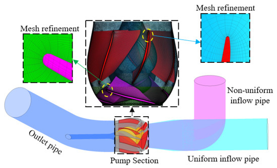
This study focuses on an emergency rescue pump used in practical engineering applications. Its key design parameters are listed in Table 1. In practical engineering applications, due to space constraints during installation, a 90° elbow is positioned 640 mm (equivalent to two times the impeller diameter) upstream of the pump impeller inlet. This elbow induces a non-uniform flow pattern at the impeller inlet, resulting in an efficiency reduction of approximately 5% compared to operation under uniform inflow conditions. To align the computational domain with the practical engineering setup, the domain is divided into four sections: the inlet pipe, impeller, guide vanes, and outlet pipe. For the non-uniform inflow condition, the inlet pipe is modeled as a 90° elbow located 640 mm upstream of the impeller inlet. In contrast, for the uniform inflow condition, the inlet pipe is straight and has the same length as the elbow pipe. The computational domains for uniform and non-uniform flow conditions are shown in Figure 2.
Table 1.
Key design parameters of the original model.
Figure 2.
Computational domain construction and grid division.
Because grid quality directly affects computational convergence and accuracy, the computational domain was discretized using a structured hexahedral mesh to ensure high mesh quality and controllable resolution. Specifically, the inlet and outlet pipes were meshed in ICEM using an O-type topology, while the impeller and guide vanes were meshed in Turbogrid with Y-type and C-type topologies, respectively. To accurately resolve the near-wall flow, the mesh adjacent to all wall surfaces was locally refined.
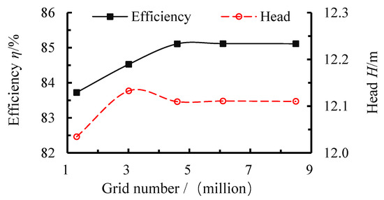
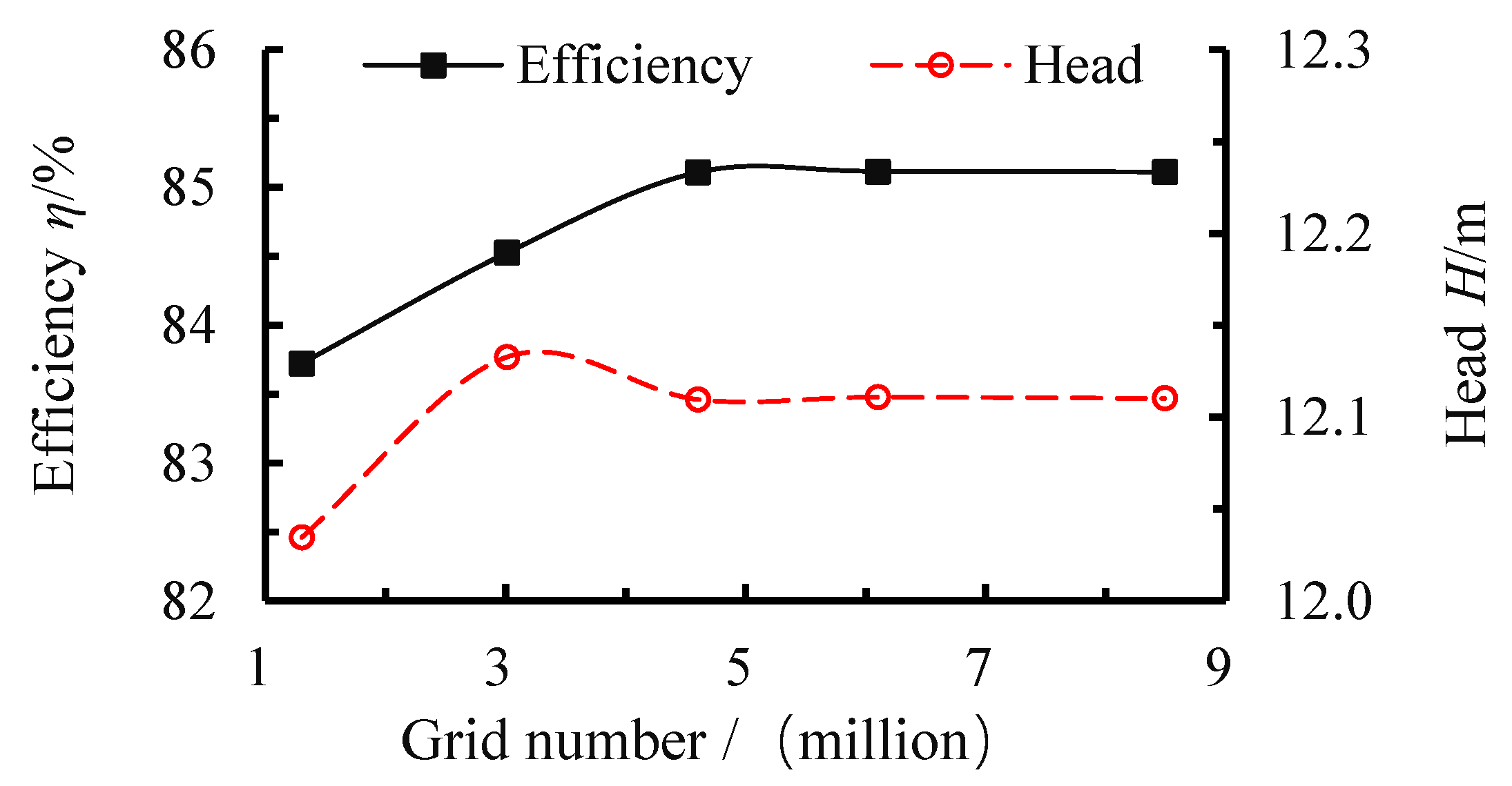
Since grid resolution strongly influences both computational cost and solution accuracy, head and efficiency were selected as the assessment criteria, calculated using Equations (3) and (4). Five grid-independence schemes were evaluated, and the results are presented in Figure 3. Both efficiency and head increased with grid density and approached asymptotic values once the total cell count exceeded approximately 4.6 million. Therefore, Scheme 3 was selected for the grid configuration used in subsequent simulations.
where and denote the total outlet and inlet pressures, respectively; denotes density; g denotes gravitational acceleration; M denotes torque; and denotes rotational angular velocity.
Figure 3.
Grid-independence verification.
3.3. Experimental Verification
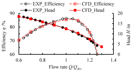
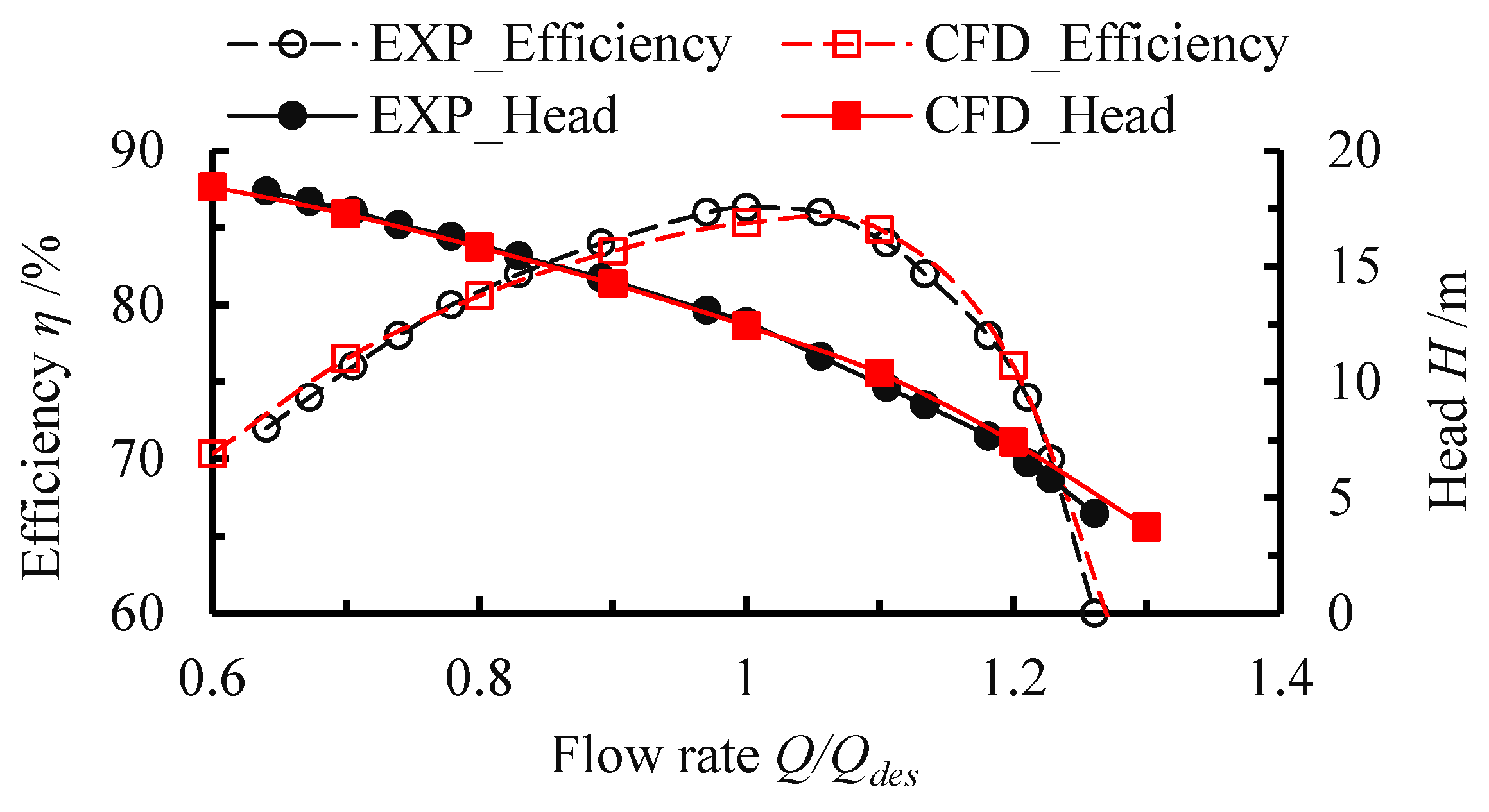
Figure 4 compares the numerical results with the experimental data obtained from the Tianjin bench test of the South-to-North Water Diversion Project, where the experimental measurements have been corrected for unloaded losses, including mechanical, volumetric, and frictional losses. In the figure, EXP_Efficiency and EXP_Head represent experimental efficiency and head, while CFD_Efficiency and CFD_Head denote computational efficiency and head from numerical simulations. As shown in Figure 4, the numerical and experimental results exhibit good agreement across the entire operating range, with the maximum deviation being below 3%. It is worth noting that at certain operating points, the simulated values are slightly lower than the experimental data, which can be attributed primarily to the tendency of turbulence models to overpredict turbulence levels [25,26]. It should be noted that under non-uniform inflow conditions, the computational setup is nearly identical to that under uniform inflow, including the turbulence model, mesh generation, and boundary condition configurations. The only difference lies in the inlet pipe geometry. Therefore, the numerical method can be considered to provide the same level of predictive accuracy for both non-uniform and uniform inflow conditions [26].
Figure 4.
Experimental validation of numerical simulations.
4. Orthogonal Experimental Design and Analysis
4.1. Design Parameters and Optimization Objectives
In this study, all loading control parameters at the hub and shroud were treated as design parameters. Consequently, eight design parameters were employed, with their ranges referenced from the research group’s prior work [25], specifically: NCh ranged from 0.1 to 0.4, NDh from 0.4 to 0.8, Kh from −1.5 to 1.5, LEh from −0.2 to 0.2, NCs from 0.1 to 0.4, NDs from 0.4 to 0.8, Ks from −1.5 to 1.5, and LEs from −0.2 to 0.2, where subscripts h and s denote hub and shroud, respectively.
To broaden the high-efficiency operating range of the optimized model and comprehensively evaluate the influence of inflow conditions on the response relationship between performance and parameters of mixed-flow pumps under various operating conditions, as well as their impact on optimization outcomes, the efficiency values at 0.8, 1.0, and 1.2 times the design flow rate were adopted as optimization targets. The weighting coefficients, referenced from the research group’s prior study, were set at 0.2, 0.5, and 0.3, respectively. It should be noted that the operation stability and anti-cavitation performance also have a great influence on the performance of the pump, but to save computing resources, it is not discussed in this study.
4.2. Orthogonal Test Design and Computational Results
To intuitively reflect the trend of optimization objectives changing with the number of design parameter levels and minimize computational complexity, all design parameter levels in this study were set to 3. Considering that the number of design parameters in this study is eight and an additional blank column KB is added to verify the effectiveness of the orthogonal design, the first nine columns of the L27(39) standard orthogonal table were used to construct the experimental design. The results are shown in Table 2. Using the aforementioned inverse design method to shape different numbered models, and using the aforementioned numerical simulation settings to calculate each model, the calculation results are shown in the table below. From the table, it can be seen that the performance of the model has undergone significant changes with the variation in parameters, and the amplitude of the model performance change varies under different inflow conditions. This preliminarily indicates that it is necessary to consider the inflow conditions at the beginning of the optimization design of mixed-flow pumps.
Table 2.
Orthogonal experiment and computation results.
4.3. Parameter Analysis
As a means of data variability analysis, range analysis has been widely used in the field of orthogonal test data analysis because of its simple calculation, intuitive results, and strong applicability [26,27]. To analyze the influence of inflow conditions on the response relationship between design parameters and optimization objectives, the data in Table 2 are analyzed by range analysis, and the results are shown in Table 3.
Table 3.
Range analysis results under different inlet flow conditions.
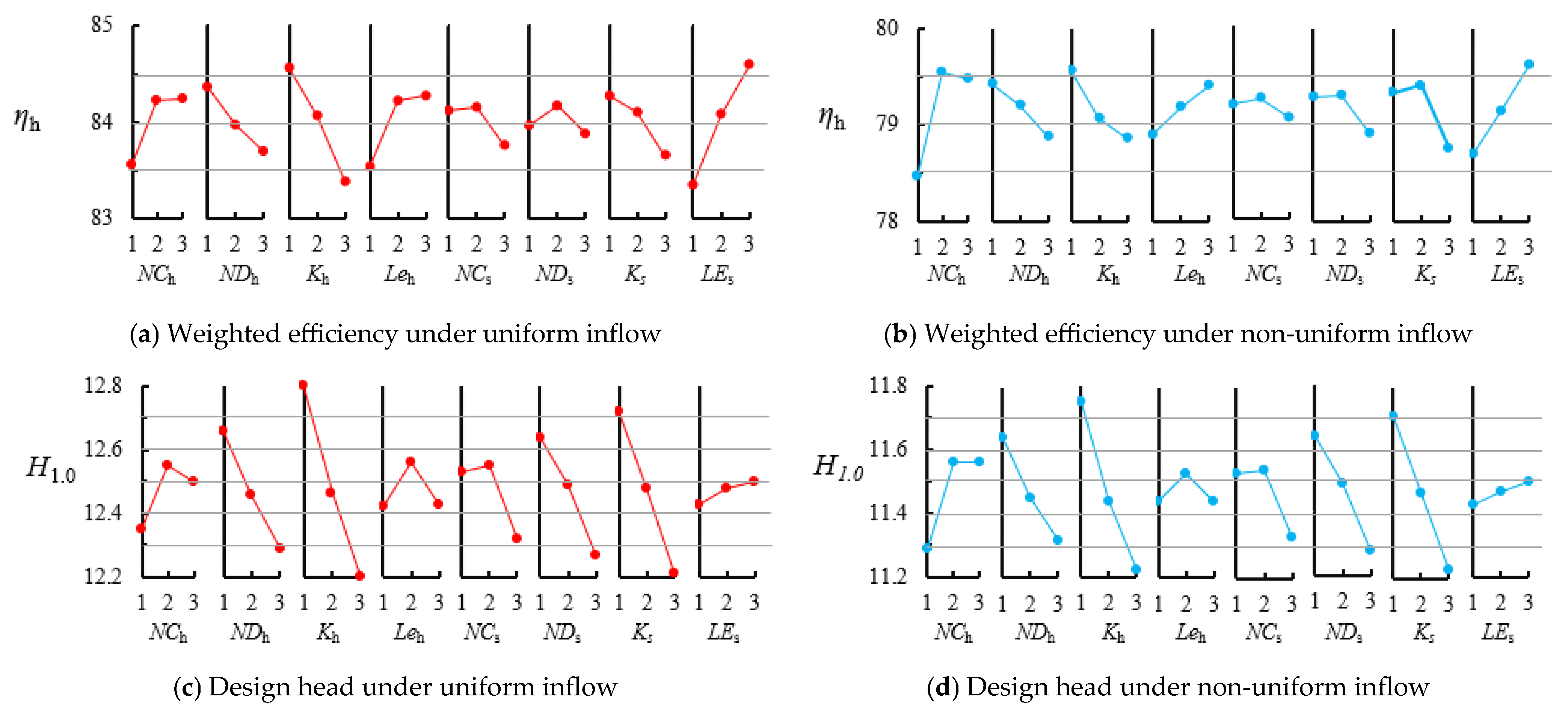
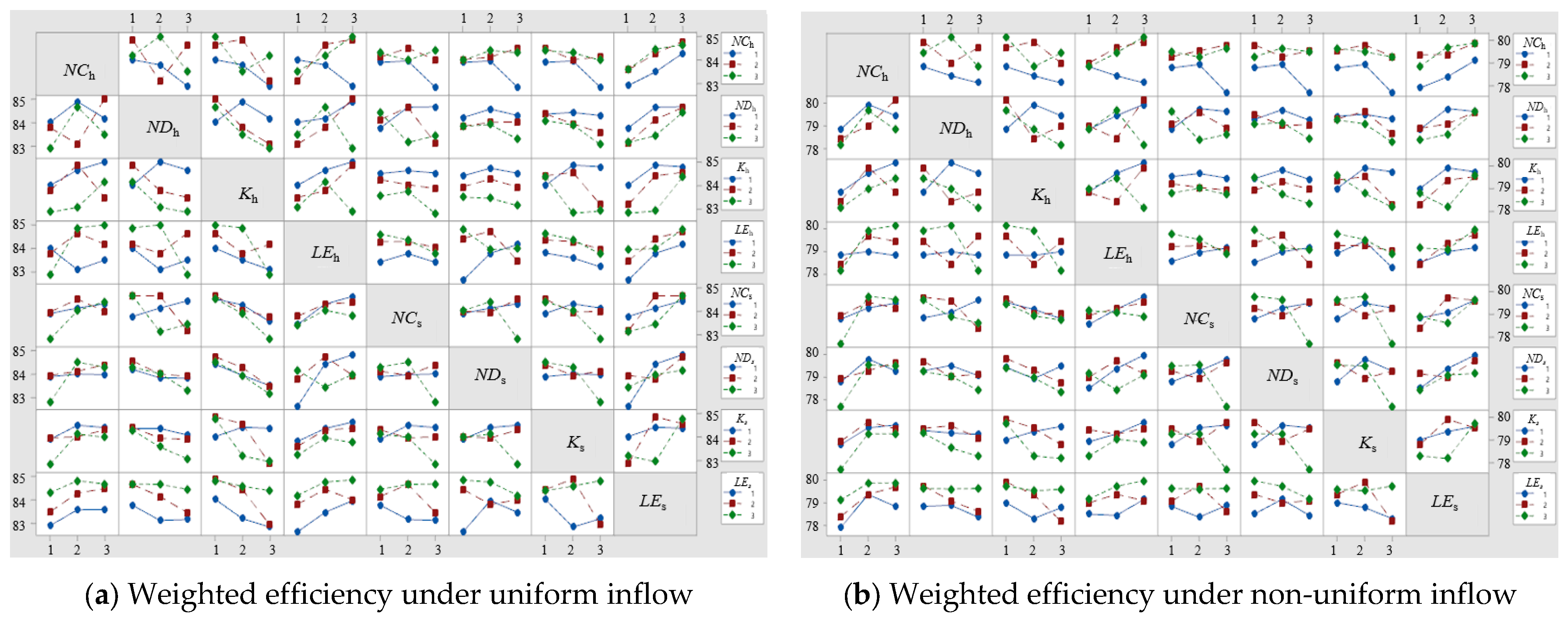
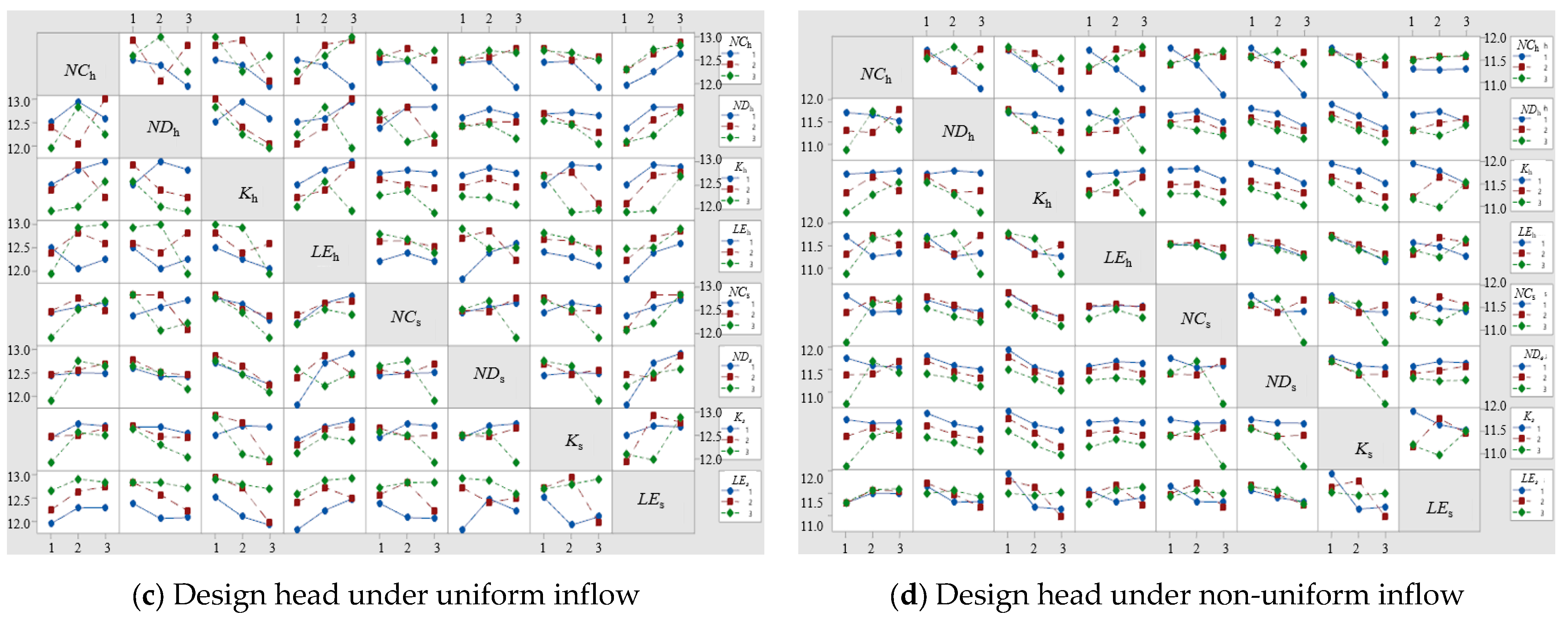
According to Table 3, among all ranks, the rank of parameter KB is the lowest, indicating that the orthogonal experiment is effective. In terms of weighted efficiency, the ranking of parameters under uniform inflow is LEs > Kh > LEh > NDh > NCh > Ks > NCs > NDs > KB, while under non-uniform inflow, the ranking of parameters is NCh > LEs > Kh > Ks > NDh > LEh > NDs > NCs > KB. There is a significant difference between the two. Specifically, the parameter NCh has the most significant impact on weighted efficiency under non-uniform inflow conditions, but its influence is relatively small under uniform inflow conditions. The parameter LEh has a relatively small impact on the weighted efficiency under non-uniform inflow, but its impact on uniform inflow is significant. The parameter LE represents the leading-edge preloading value, which governs the incidence condition at the impeller inlet and therefore plays a critical role in impeller performance. However, under the condition of non-uniform inflow, the radial distribution of the attack angle at the impeller inlet is extremely uneven and in a changing state, so the influence of LE decreases. In comparison, non-uniform inflow causes severe flow separation on the hub side. The NCh determines the axial position where the main loading begins on the hub side, and its numerical variation corresponds to adjusting the position where the blade starts to exert its primary corrective effect on the distorted flow field. Therefore, it exerts the greatest influence on pump performance under non-uniform inflow conditions. For the head, the ranking of parameters under uniform inflow is Kh > Ks > NDs > NDh > NCs > NCh > LEh > LEs > KB, while under non-uniform inflow, the ranking of parameters is Kh > Ks > NDs > NDh > NCh > NCs > LEh > LEs > KB. The ranking of parameters for the head is almost the same under both inflow conditions, with only the order of parameters NCh and NCs changing. Therefore, the inflow conditions significantly affect the response relationship between various parameters and the weighted efficiency of the mixed-flow pump. Under different inflow conditions, the design parameters that should be focused on are different.
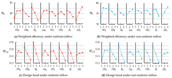
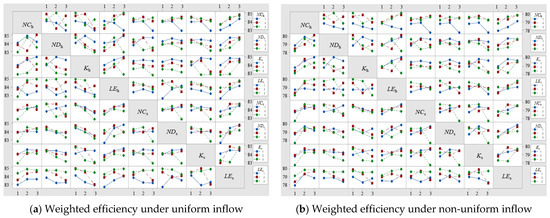
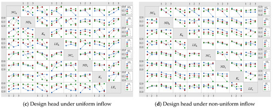
Figure 5 and Figure 6 present the main effects and interaction effects of various parameters based on analysis of variance. According to the results of the main effect analysis, the rank of the parameters on the weighted efficiency and head under the uniform inflow condition is: LEs > Kh > LEh > NDh > NCh > Ks > NCs > NDs and Kh > Ks > NDs > NDh > NCs > NCh > LEh > LEs. Under the non-uniform inflow condition, the rank of the parameters on the weighted efficiency and head is: NCh > LEs > Kh > Ks > NDh > LEh> NDs> NCs and Kh > Ks > NDs > NDh > NCh > NCs > LEh > LEs. It can be seen that the main effect analysis results are consistent with the range analysis results. The analysis of parameter interaction effects indicates that interactions exist among all parameters, albeit to varying degrees, and generally follow a consistent pattern: strong interactions are observed between hub-side load control parameters (NCh, NDh, Kh, and LEh), as well as between shroud-side load control parameters (NCs, NDs, Ks, and LEs). In contrast, interactions between hub-side and shroud-side parameters are relatively weak. This is primarily because NCh, NDh, Kh, and LEh collectively determine the loading distribution at the hub, while NCs, NDs, Ks, and LEs collectively determine the loading distribution at the shroud.
Figure 5.
Main effects of design parameters.
Figure 6.
Interaction effects of design parameters.
4.4. Optimization Results
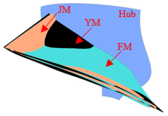
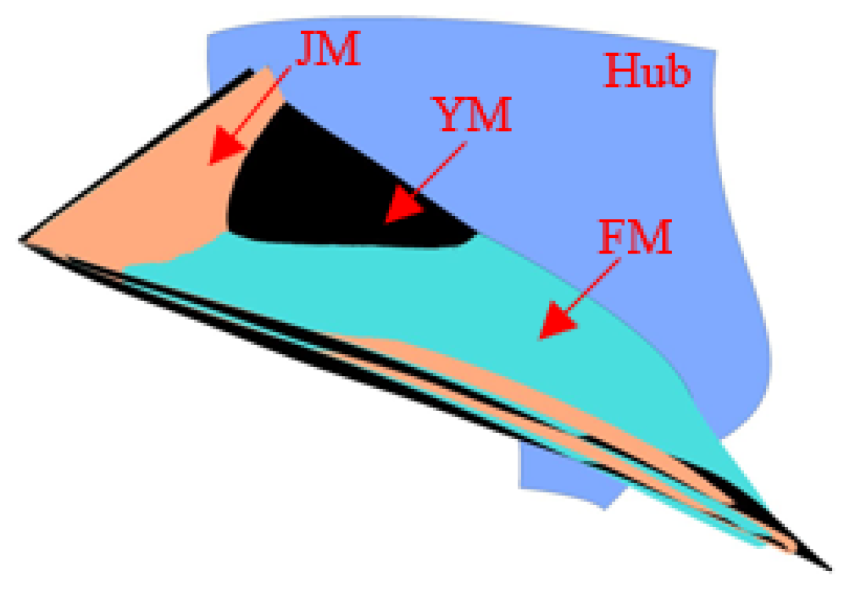
The parameter levels directly influence the performance of the optimized model. In this study, their selection is based on the following criteria. First, the parameters exhibiting the strongest influence on the weighted efficiency are identified, and the level of each of these parameters is chosen to maximize the efficiency. For the remaining parameters, the levels are selected primarily to mitigate the head fluctuation induced by the above choices, thereby ensuring that the head variation in the optimized model remains within the acceptable range. After careful consideration, the levels of the optimal model parameters NCh, NDh, Kh, LEh, NCs, NDs, Ks, and LEs are set to 2, 1, 2, 3, 1, 2, 3, and 1, respectively, and the corresponding values are 0.25, 0.4, 0, 0.2, 0.1, 0.6, 1.5, and -0.2, respectively. Under the condition of non-uniform inflow, the levels of the above parameters are set as 3, 2, 1, 1, 1, 3, 2, and 2, and the corresponding values are 0.4, 0.6, 1.5, −0.2, 0.1, 0.8, 0, and 0, respectively. Therefore, the inflow conditions have a great influence on the parameters corresponding to the final optimization results of the mixed-flow pump. It should be noted that this study only focused on uniform inflow and 90° bend inflow. Both the ranking of parameters and the optimal parameter combinations underwent significant changes. However, these variations may be associated with the degree of distorted inflow, which warrants special attention in future research. However, in the face of real engineering problems, especially under complex working conditions, designers cannot be obsessed with the best combination of past research; that is, the idea should be changed from ‘finding a set of universal optimal parameters’ to ‘prioritizing the definition or evaluation of expected inflow conditions’. If there are large changes or uncertainties in the inflow conditions, the designer should abandon the pursuit of peak performance under a single condition and instead seek a robust design within the expected operating conditions. Figure 7 shows the comparison of impeller blade shapes corresponding to the original model, YM; uniform inflow optimization result, JM; and non-uniform inflow optimization result, FM. It can be seen that there are great differences in the three geometric shapes, especially in the middle and front of the blade, which fully illustrates the necessity of considering inflow conditions in the optimization.
Figure 7.
Comparison of blade profiles.
5. Results and Analysis
5.1. Comparison of External Characteristics
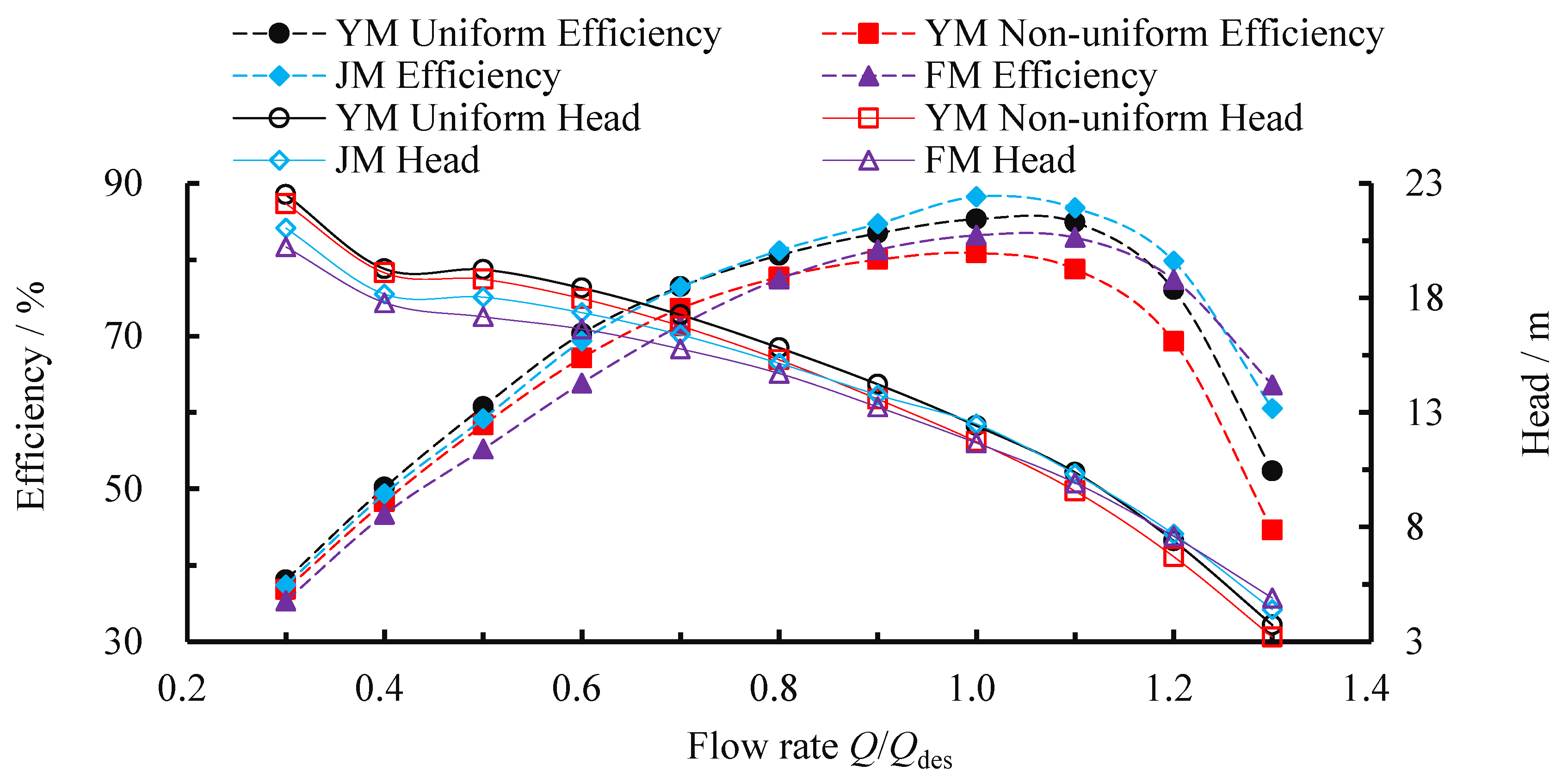
To investigate the effect of inflow conditions on mixed-flow pump performance and to analyze changes in model performance before and after optimization under different inflow conditions, the energy characteristics of YM, JM, and FM were compared (Figure 8). In the figure, the legends are defined as follows: YM Uniform Efficiency and YM Uniform Head denote the efficiency and head of YM under uniform inflow conditions; YM Non-uniform Efficiency and YM Non-uniform Head denote the efficiency and head of YM under non-uniform inflow conditions; JM Efficiency and JM Head denote the efficiency and head of JM under uniform inflow conditions; and FM Efficiency and FM Head denote the efficiency and head of FM under non-uniform inflow conditions.
Figure 8.
Comparison of model performance before and after optimization under different inflow conditions.
For YM, the efficiency and head of non-uniform inflow under all working conditions have decreased compared with uniform inflow, and with the increase in flow, the efficiency difference between the two gradually increases, while the head difference first increases and then decreases. Specifically, at 0.8Qdes, 1.0Qdes, and 1.2Qdes, the efficiency corresponding to uniform inflow is 81.59%, 85.31%, and 76.07%, while the efficiency corresponding to non-uniform inflow is 77.72%, 80.89%, and 69.30%, and the difference between the two is 2.87%, 4.42%, and 6.78%, respectively. Similarly, at 0.8Qdes, 1.0Qdes, and 1.2Qdes, the head difference between them is 0.52 m, 0.70 m, and 0.69 m, respectively, and the maximum difference in head occurs at 1.1Qdes, which is 0.81 m. It is noteworthy that under high-flow conditions, non-uniform inflow results in a greater reduction in head compared to uniform inflow. Lower head tends to cause rapid efficiency decline and increased pressure pulsation intensity. Therefore, when mixed-flow pumps operate under non-uniform inflow conditions, it is particularly important to avoid running them at high flow rates.
Under the two inflow conditions, the performance of the optimized model is more efficient than that of the original model in the common flow range, and the head is basically the same under the design condition. Therefore, the optimization has achieved satisfactory results under both inflow conditions. It is worth noting that under low-flow conditions, the optimized model consistently exhibits lower head than the original model, while the reverse trend is observed under high-flow conditions. Specifically, the head of the optimized model varies more gradually with changes in flow rate. This behavior is primarily related to the use of blade loading as design parameters in the inverse design method, which results in blade shapes that better conform to the pump’s internal flow dynamics and, therefore, exhibit greater robustness against flow variations. In addition, under different inflow conditions, the improvement amplitude of the two models before and after optimization is different. Specifically, under uniform inflow, the efficiency of the JM model at 0.8Qdes, 1.0Qdes, and 1.2Qdes conditions is increased by 0.61%, 2.94%, and 3.74%, respectively, compared with those of the YM model. Under non-uniform inflow, the efficiency of the FM model increased by 0.23%, 4.42%, and 6.78%, respectively, compared with the YM model. In particular, the maximum efficiency improvement occurred at 1.3Qdes for both types of inflow, with an increase of 8.17% for uniform inflow and 19.00% for non-uniform inflow. This can be attributed to the higher head achieved by the optimized design obtained via the inverse design method, which exhibits greater robustness to flow variations.
5.2. Internal Flow Analysis
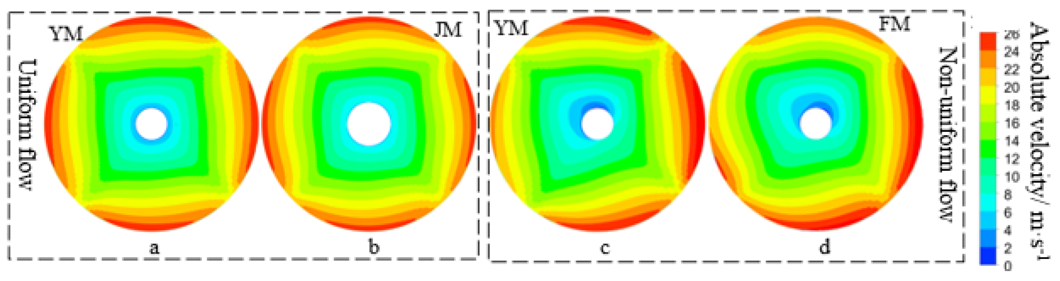
To more intuitively show the root causes of the above differences in energy characteristics, taking 1.2Qdes with large differences in efficiency as an example (the same below), the distribution of absolute velocity in the absolute coordinate system at the impeller inlet before and after optimization under different inflow conditions is compared. The results are shown in Figure 9. It can be seen that under the condition of uniform inflow, the velocity at the inlet of the impeller gradually increases from the hub to the shroud, and the velocity near the shroud changes periodically. The maximum velocity appears four times, which is consistent with the number of blades, while a low-speed zone covering the entire hub appears near the hub. Under the influence of non-uniform inflow, the original periodic velocity distribution at the inlet of the impeller is destroyed, and the high-speed area near the shroud and the low-speed area near the hub begin to deviate to one side, and their values become more extreme, which destroys the assumption of uniform inflow at the inlet of the impeller, and then leads to the decline of pump performance. Under the condition of uniform inflow, the optimized model has a more uniform velocity distribution than before. In particular, the area of the high-speed zone near the shroud is reduced, while the low-speed zone near the hub is completely suppressed. This shows that the optimized model has a smaller angle of attack by modifying the numerical value of LEh. Similarly, although the velocity distribution at the impeller inlet is distorted due to the non-uniform inflow, the velocity distribution at the hub and rim of the optimized model has been significantly improved compared with that before optimization. Therefore, optimizing the impeller blade can improve the flow pattern at the impeller inlet to a certain extent, so as to reduce the impact of adverse inflow conditions.
Figure 9.
Comparison of velocity at the impeller inlet before and after optimization. (a) YM inlet flow state under uniform inflow; (b) JM inlet flow state under uniform inflow; (c) YM inlet flow state under non-uniform inflow; (d) JM inlet flow state under non-uniform inflow.
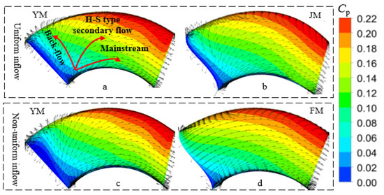
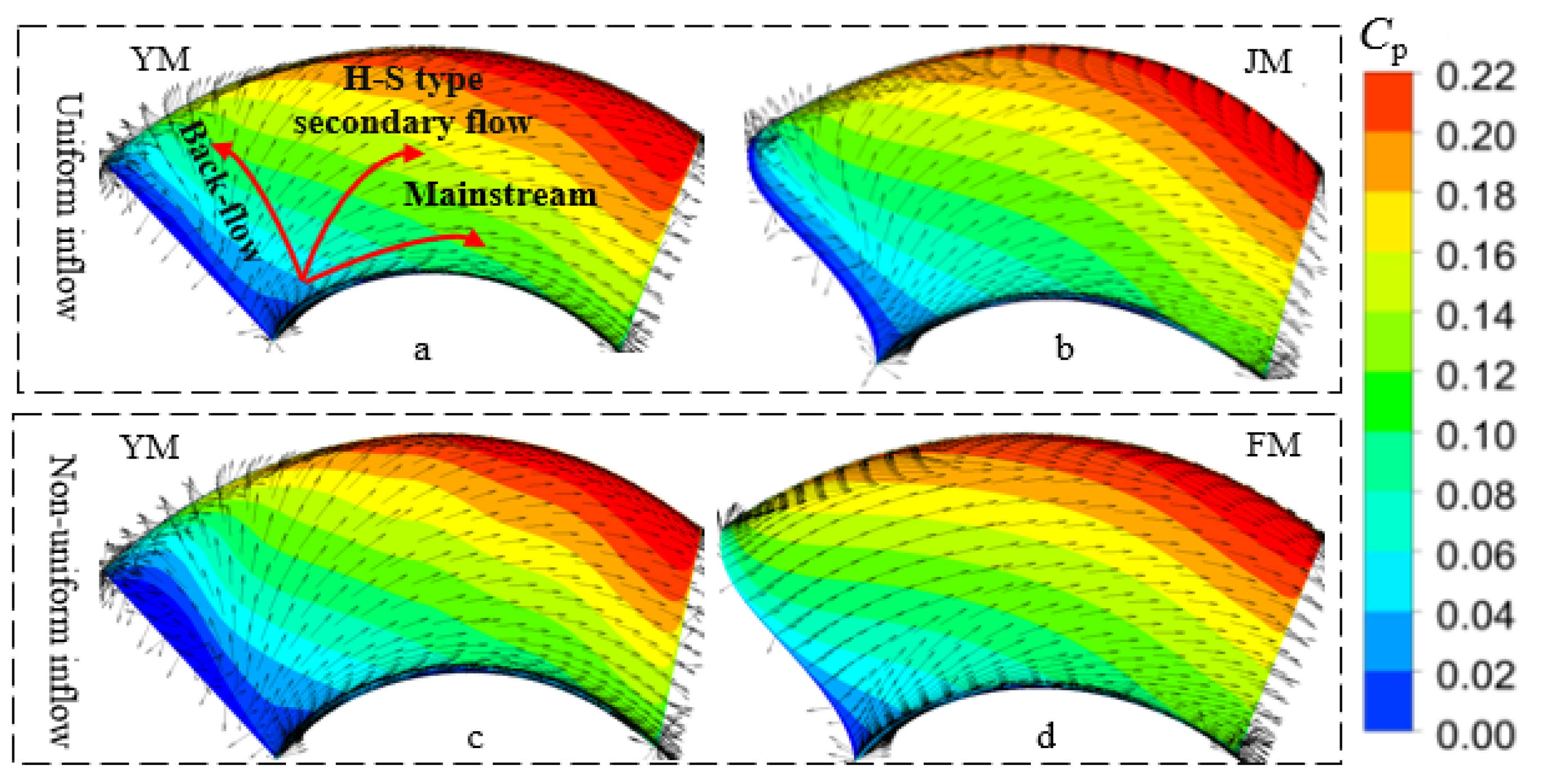
To further reveal the root cause of the impact of the flow pattern at the impeller inlet on the impeller performance, the total pressure coefficient Cp (Equation (5)) and velocity vector distributions near the impeller blade surface in the absolute coordinate system were compared, and the results are shown in Figure 10. Under uniform inflow, the total pressure increases gradually from the hub to the shroud and from the leading edge to the trailing edge. The highest and lowest values of total pressure appear at the angle between the shroud and trailing edge, and the angle between the hub and leading edge, respectively. Near the leading edge of the blade, the fluid flows from the vaneless area to the blade area, and the fluid motion state is suddenly changed to adapt to the rotating motion of the impeller. Under the joint influence of inertial force, centrifugal force, pressure gradient, and blade action, there is obvious backflow and H-S secondary flow in this area. Under the influence of non-uniform inflow, the intensity of the low-pressure zone, backflow, and H-S secondary flow near the leading edge of the blade increased. Comparing Figure 10a,b, it can be seen that under the condition of uniform inflow, the area of the low-pressure area near the leading edge of the optimized model, backflow intensity, and H-S secondary flow intensity are significantly reduced compared with the original model. Similarly, comparing Figure 10c,d, it can be seen that under the influence of non-uniform inflow, the flow pattern near the leading edge of the optimized model has been significantly improved compared with that before optimization, especially the inhibition of the low-pressure zone and backflow.
where PT denotes total pressure, and us denotes the velocity at the shroud trailing edge.
Figure 10.
Comparison of pressure and velocity distribution before and after optimization. (a) YM pressure and velocity distribution under uniform inflow; (b) JM pressure and velocity distribution under uniform inflow; (c) YM pressure and velocity distribution under non-uniform inflow; (d) JM pressure and velocity distribution under non-uniform inflow.
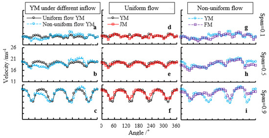
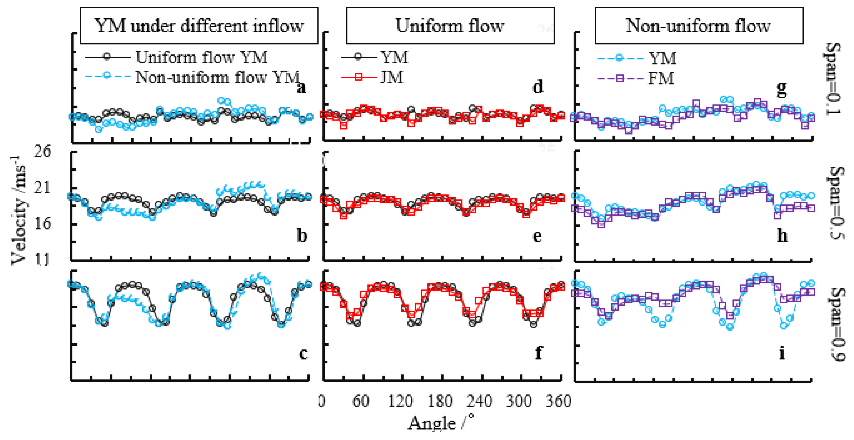
Figure 11 shows the comparison of absolute velocity distribution at different spanwise locations of the impeller outlet before and after optimization under different inflow conditions. In general, the velocity increases gradually from the hub to the shroud, and the difference between the maximum and minimum velocity at the hub is less than that at the shroud, but the velocity distribution at the shroud is more periodic, and its period is directly related to the number of blades. Comparing Figure 11a–c, it can be seen that due to the influence of non-uniform inflow, the velocity fluctuation at the impeller outlet is still greater than that of uniform inflow after the fluid passes through the impeller. Therefore, non-uniform inflow not only has a significant impact on the performance of the impeller but also affects the performance of downstream components of the impeller. From Figure 11d–f, it can be seen that under the condition of uniform inflow, the velocity fluctuation at the outlet of the model impeller after optimization has been reduced compared with that before optimization, especially from the midspan to the shroud. Similar conclusions can be obtained by comparing Figure 11g–i. Under the condition of non-uniform inflow, the reduction in velocity fluctuation near the shroud is greater than that of uniform inflow.
Figure 11.
Different span velocity distribution of impeller outlet before and after optimization. (a) YM velocity distribution at span = 0.1 under different inflow; (b) YM velocity distribution at span = 0.5 under different inflow; (c) YM velocity distribution at span = 0.9 under different inflow; (d) YM and JM velocity distribution at span = 0.1 under uniform inflow; (e) YM and JM velocity distribution at span = 0.5 under uniform inflow; (f) YM and JM velocity distribution at span = 0.9 under uniform inflow; (g) YM and FM velocity distribution at span = 0.1 under non-uniform inflow; (h) YM and FM velocity distribution at span = 0.5 under non-uniform inflow; (i) YM and FM velocity distribution at span = 0.9 under non-uniform inflow.
To quantitatively clarify the impact of inflow conditions on the energy loss of different parts of the model before and after optimization, the hydraulic loss proportion of each part (Equations (6) and (7)) is taken for comparative analysis, and the results are shown in Table 4. According to the comparison of the energy loss in each component of the original model under different inflow conditions, the non-uniform inflow will lead to a significant increase in the hydraulic loss in each component, especially in the inlet pipe, which can increase by more than 340%. According to the comparison of hydraulic losses in the YM and JM components under the condition of uniform inflow, the hydraulic losses in the JM impeller and its downstream components are reduced compared with those before optimization, and the reduce in the impeller is the most obvious, which indicates that the optimization has a significant effect on improving the efficiency of the impeller. Similar conclusions can be obtained under the condition of non-uniform inflow, and the hydraulic loss in the impeller is reduced more obviously, which is related to the weak resistance of the uniform inflow assumption adopted by YM to non-uniform inflow, while FM has considered the influence of non-uniform inflow at the beginning of design.
where and denote the total pressure at the outlet and inlet of the calculated component, respectively; and denote the hydraulic loss proportion of the impeller and other parts, respectively.
Table 4.
Proportion of hydraulic loss of different components under different inflow conditions.
6. Conclusions
In this study, through coupled inverse design and orthogonal experimental design methods, parameter analysis and optimization were conducted on the same mixed-flow pump under both uniform and non-uniform inflow conditions. The design parameters were loading control parameters at the hub and shroud, while the optimization targets were weighted efficiencies at operating conditions of 0.8Qdes, 1.0Qdes, and 1.2Qdes. The main conclusions are as follows:
(1) Under uniform and non-uniform inflow conditions, the rank of design parameters on the weighted efficiency is LEs > Kh > LEh > NDh > NCh > Ks > NCs > NDs and NCh > LEs > Kh > Ks > NDh > LEh > NDs > NCs, respectively. The values of the parameters NCh, NDh, Kh, LEh, NCs, NDs, Ks, and LEs corresponding to the optimal models are 0.25, 0.4, 0, 0.2, 0.1, 0.6, 1.5, and −0.2, and 0.4, 0.6, 1.5, −0.2, 0.1, 0.8, 0, and 0, respectively. Therefore, the inflow conditions significantly affect the response relationship between the design parameters and the weighted efficiency, as well as the optimal model blade shape.
(2) Under the condition of uniform and non-uniform inflow, the optimized model increased by 0.61%, 2.94%, and 3.74%, and 0.23%, 4.42%, and 6.78%, respectively, compared with that before optimization. The analysis of hydraulic loss shows that the reduction in hydraulic loss of the optimized model impeller under non-uniform inflow conditions is significantly greater than that under uniform inflow conditions. Therefore, considering the influence of inflow conditions at the beginning of design can significantly enhance the resistance of the optimized model to non-uniform incoming flow. Therefore, it is feasible and necessary to consider the influence of inflow conditions in pump design.
In this study, to limit computational cost, each design parameter was assigned three discrete levels, which may neglect the nonlinear response of certain parameters. In the future, we will investigate the optimal design of mixed-flow pumps under different inlet conditions by employing an optimization strategy that can predict the performance of a large number of cases with less computational effort, namely by combining approximate models and optimization algorithms. Furthermore, we will explore the application of the aforementioned optimization measures in enhancing the anti-cavitation performance and operational stability of pumps.
Author Contributions
Conceptualization and writing—original draft: J.W.; Data curation, methodology, visualization, and formal analysis: W.Z., Y.Y. and C.S.; Writing—review and editing: Y.F.; Supervision and funding acquisition: M.W. All authors have read and agreed to the published version of the manuscript.
Funding
This work was supported by the Postdoctoral Foundation (No. 2023M741499), the Natural Science Foundation of Jiangsu Province (No. SBK2023042972), and the Open Project of Jiangsu High Efficiency and Energy Saving Large Axial Flow Pump Station Engineering Research Center (ECHEAP022).
Data Availability Statement
All necessary data have been included in the text. Further information is available from the author.
Acknowledgments
The authors thank the editors and anonymous reviewers for their comments and suggestions on this article.
Conflicts of Interest
The authors declare no conflicts of interest.
References
- Sedlá, M.; Abrahámek, P. Numerical study on the performance of a pumping station with bell-mouth-based vertical pumps during an accidental shutdown. Processes 2024, 12, 630. [Google Scholar] [CrossRef] [Scilit]
- Diallo, A.B.; Nar, H.; Yapc, R. Analysis of fluid forces impacting on the impeller of a mixed flow blood pump with computational fluid dynamics. Int. J. Artif. Organs 2024, 47, 894–907. [Google Scholar] [CrossRef] [Scilit] [PubMed]
- Wang, M.C.; Chen, S.S.; Gu, Y.D.; Yang, Y.; Xia, Z.; Chen, J. Effect of free and compound vortex designs on the energy characteristics and operational stability of mixed flow pumps. Phys. Fluids 2024, 36, 085186. [Google Scholar] [CrossRef] [Scilit]
- Wang, M.C.; Ding, Z.; Lu, J.; Shi, L.; Chen, J.; Yang, Y.; Gu, Y.; Zhang, F. Effect of different loading distribution forms on the energy characteristics of mixed-flow pumps. Phys. Fluids 2025, 37, 015226. [Google Scholar] [CrossRef] [Scilit]
- Heo, M.W.; Kim, K.Y.; Kim, J.H.; Choi, Y.S. High-efficiency design of a mixed-flow pump using a surrogate model. J. Mech. Sci. Technol. 2016, 30, 541–547. [Google Scholar] [CrossRef] [Scilit]
- Kim, S.; Kim, Y.I.; Kim, J.H.; Choi, Y.S. Design optimization for mixed-flow pump impeller by improved suction performance and efficiency with variables of specific speeds. J. Mech. Sci. Technol. 2020, 34, 2377–2389. [Google Scholar] [CrossRef] [Scilit]
- Li, W.; Yang, Q.; Yang, Y.; Ji, L.; Shi, W.; Agarwal, R. Optimization of pump transient energy characteristics based on response surface optimization model and computational fluid dynamics. Appl. Energy 2024, 362, 123038. [Google Scholar] [CrossRef] [Scilit]
- Ding, Z.; Yuan, J.; Chen, Y.; Dai, Q.; Chen, S.; Wang, M. Multi-condition optimization of guide vane mixed-flow pump based on parameter analysis and intelligent optimization. J. Drain. Irrig. Mach. Eng. 2025, 43, 348–356. [Google Scholar]
- Sun, Z.; Zhu, Y.; Zhang, J.; Lv, N.; Tang, F.; Chen, S. Optimization of high specific speed mixed flow pump impeller based on hydrofoils with different maximum camber positions. Trans. Chin. Soc. Agric. Mach. 2024, 55, 249–256+305. [Google Scholar]
- He, S. Multi-Objective Optimization and Cavitation Characteristic Analysis of Volute-Type Mixed-Flow Pump Based on ISIGHT Platform. Master’s Thesis, Jiangsu University, Zhenjiang, China, 2019. [Google Scholar]
- Vagnoli, S.; Verstraete, T. URANS analysis of the effect of realistic inlet distortions on the stall inception of a centrifugal compressor. Comput. Fluids 2015, 116, 192–204. [Google Scholar] [CrossRef] [Scilit]
- Zheng, Y.H.; Gu, Z.C.; Li, Y.J.; Zhu, X.; Meng, F.; Wang, M. Entropy production analysis for energy dissipation of a vertical mixed-flow pump device under asymmetric inflow conditions. Proc. Inst. Mech. Eng. Part C J. Mech. Eng. Sci. 2022, 236, 10426–10439. [Google Scholar] [CrossRef] [Scilit]
- Zheng, Y.H.; Li, Y.J.; Zhu, X.Y.; Xu, X.; Meng, F. Numerical investigation of entropy hydraulic loss analysis and vortical structure suppression in mixed flow pump device under lateral inflow. Proc. Inst. Mech. Eng. Part E-J. Process Mech. Eng. 2023, 237, 1529–1545. [Google Scholar] [CrossRef] [Scilit]
- Yao, H.Z. Study of Inlet Inflow Distortion on the Unsteady Excitation Characteristics of Centrifugal Pumps. Master’s Thesis, Xihua University, Chengdu, China, 2024. (In Chinese) [Google Scholar]
- Drǎghici, I.; Muntean, S.; Bosioc, A.I.; Anton, L.E. LDV measurements of the velocity field on the inlet section of a pumped storage equipped with a symmetrical suction elbow for variable discharge values. IOP Conf. Ser. Earth Environ. Sci. 2014, 22, 032017. [Google Scholar] [CrossRef] [Scilit]
- Li, J.C.; Deng, Y.Y.; Zhang, X.Y.; Wang, W.; Fan, B.; Peng, F. Instability prediction under distorted inflow based on deep learning neural networks in an axial flow compressor. Phys. Fluids 2024, 36, 127163. [Google Scholar] [CrossRef] [Scilit]
- Van Esch, B.P.M. Performance and Radial loading of a mixed-flow pump under non-uniform suction flow. J. Fluids Eng. Trans. ASME 2009, 131, 051101. [Google Scholar] [CrossRef] [Scilit]
- Cao, P.Y.; Yue, R.; Zhang, J.F.; Liu, X.; Wu, G.; Zhu, R. Proper orthogonal decomposition based response analysis of inlet distortion on a waterjet pump. Water 2024, 16, 1282. [Google Scholar] [CrossRef] [Scilit]
- Quan, H.; Wang, Z.S.; Du, Y.Y.; Su, H. Research on performance failure caused by gas blocking in multiphase mixed-transport pump under non-uniform inflow conditions. J. Braz. Soc. Mech. Sci. Eng. 2024, 46, 346. [Google Scholar] [CrossRef] [Scilit]
- Zangeneh, M. Three-Dimensional Design of Radial-Inflow Turbines. Ph.D. Thesis, University of Cambridge, London, UK, 1988. [Google Scholar]
- Zanetti, G.; Siviero, M.; Cavazzini, G.; Santolin, A. Application of the 3D inverse design method in reversible pump turbines and francis turbines. Water 2023, 15, 2271. [Google Scholar] [CrossRef] [Scilit]
- Wang, P. Multi-Objective Design of a Transonic Turbocharger Compressor with Reduced Noise and Increase Efficiency. Ph.D. Thesis, University of London, London, UK, 2017. [Google Scholar]
- Kim, B.; Siddique, M.H.; Samad, A.; Hu, G.; Lee, D.-E. Optimization of centrifugal pump impeller for pumping viscous fluids using direct design optimization technique. Machines 2022, 10, 774. [Google Scholar] [CrossRef] [Scilit]
- Mohammedali, A.A.M.; Kim, K. Development of high-efficient centrifugal pump through optimization of its volute tongue and expeller vane. J. Fluids Eng. 2021, 143, 071204. [Google Scholar] [CrossRef] [Scilit]
- Zhang, X.; Wang, P.; Ruan, X. Unsteady flow characteristics of mixed-flow pumps with splitter blades. Trans. Chin. Soc. Agric. Mach. 2021, 52, 153–160. (In Chinese) [Google Scholar]
- Yuan, Y. Inner Flow Mechanism and Optimization Design of a Vehicle Fire Centrifugal Pump. Ph.D. Thesis, Jiangsu University, Zhenjiang, China.
- Wang, M.C.; Ni, X.; Chen, J.Q.; Li, X.; Meng, F.; Yang, Y.; Gu, Y. Energy performance improvement of mixed flow pump based on coupling of geometric and hydrodynamic parameters. Energy 2025, 332, 137243. [Google Scholar] [CrossRef] [Scilit]

Disclaimer/Publisher’s Note: The statements, opinions and data contained in all publications are solely those of the individual author(s) and contributor(s) and not of MDPI and/or the editor(s). MDPI and/or the editor(s) disclaim responsibility for any injury to people or property resulting from any ideas, methods, instructions or products referred to in the content. |
© 2026 by the authors. Licensee MDPI, Basel, Switzerland. This article is an open access article distributed under the terms and conditions of the Creative Commons Attribution (CC BY) license.