


Abstract
To address the failure risks associated with long-term service of subsea Christmas tree-wellhead systems under the complex marine environment of the South China Sea, a multi-factor coupled mechanical analysis method is proposed to evaluate the system’s mechanical characteristics and ensure the safety of deepwater oil and gas production. A dynamic model of lateral vibration under seismic loading is established, considering the combined effects of earthquakes, ocean currents, and seabed soil resistance. Based on the actual operating parameters of a well in the Lingshui area of the South China Sea, a three-dimensional finite element model of the subsea Christmas tree-wellhead assembly was developed in ABAQUS 2023. The combined effects of ocean currents, seismic loading, and corrosion over long-term service were simulated to compute and analyze the distributions of stress, bending moment, and associated failure risk. The results indicate that, under a once-in-a-century current combined with seismic waves of intensity V–VI, the system risk remains controllable. However, when the seismic intensity exceeds level VII, the maximum stress and bending moment reach 324.9 MPa and 6.02 MN·m, respectively, surpassing the allowable limits for an X56-grade surface conductor. Considering corrosion effects over a 25-year service life, the extreme stress values increase by 1–5% while the bending moment increases slightly; corrosion significantly amplifies the system’s failure risk. An analysis of the mudline burial height of the subsea wellhead during long-term service shows that, within a range of 1–7 m, variations in system loading are minimal. Based on the mechanical characteristics analysis, it is recommended that the design of subsea Christmas trees and wellheads incorporate regional seismic history, specify X56-grade surface conductors to mitigate corrosion effects, and install leakage-monitoring devices at critical locations to ensure the long-term service safety of the subsea Christmas tree-wellhead system.
1. Introduction
China’s crude oil external dependence has long remained above 70%, highlighting the increasing importance of energy security [1,2]. In recent years, 76% of the world’s newly proven oil and gas resources have come from offshore areas [3]. In the 2024 global top ten oil and gas discoveries list, offshore discoveries accounted for seven spots, with six located in deepwater-ultra-deepwater areas [4], demonstrating the vast potential of oil and gas resources in this field. Deepwater oil and gas have become a significant growth pole for China’s “increasing reserves and production,” which is crucial for ensuring economic development and national energy security. Traditional shallow water areas mostly use jacket platforms for development; however, as water depth increases, the construction and installation costs of jacket platforms rise sharply. Subsea production systems, with subsea Christmas trees and subsea wellheads as key equipment, effectively address production challenges in waters deeper than 300 m and are widely used in domestic and international offshore deepwater oil and gas field development [5,6]. The lifespan of offshore oil and gas fields is generally around 20–30 years; therefore, subsea Christmas trees need to serve long-term on the seabed, placing extremely high demands on their reliability. However, the marine environment is complex; factors such as current scour, corrosion, and earthquakes may cause subsidence or tilting of the subsea Christmas tree-wellhead system, leading to production interruption or even oil and gas leakage. Thus, it is imperative to conduct mechanical analysis and verification of the subsea Christmas tree-wellhead system under in-service conditions to ensure the safe production of deepwater oil and gas fields [7,8,9].
Domestic and international research has conducted a series of studies on the forces and stability of subsea Christmas trees and wellheads. Yang Jin et al., based on the principle of vertical mechanical balance during the jetting process of deepwater oil and gas surface conductors, revealed the variation law of lateral frictional resistance of the surface conductor with depth and time, and established a depth prediction model for surface conductor installation using the deepwater jetting method [10]. Based on deepwater drilling operational loads, ANSYS software was used to analyze subsea wellhead stability [11]. Addressing the needs for deepwater drilling speed enhancement under new circumstances, an efficient “three-in-one” shallow drilling operation mode was proposed [12], achieving a deepwater efficient drilling method that allows running the surface conductor, surface casing, and technical casing in a single trip. Zhou B. et al. [13,14,15], from the perspective of jetting disturbance, established a real-time bearing capacity calculation model considering surface conductor jetting installation parameters through jetting simulation experiments, analyzing the effects of conductor size, wellhead inclination, mudline height, and top tension on conductor stability. Su K.H. et al. [16,17,18,19,20,21,22] comprehensively considered factors such as deepwater environmental loads, platform motion, and riser disturbance, establishing an integrated stability analysis method for the platform-riser-subsea wellhead system, exploring the impact of deepwater shallow soil properties on wellhead stability and fatigue. Chang Y.J. et al. [23,24,25,26,27,28,29] established a fatigue model for the subsea wellhead system, systematically considering the effects of vortex-induced vibration, wave-induced vibration, temperature, wellhead type, soil loads, etc., on fatigue life, concluding that environmental loads, BOP size and weight, wellhead type, as well as weld quality and location are key factors affecting wellhead fatigue damage. Wang Y.B. et al. [30,31,32,33,34] developed a pile-soil interface constitutive model, used ABAQUS 6.12-3 software to calculate conductor bearing capacity, and analyzed the effects of marine environment, drilling fluid temperature and pressure, and auxiliary pipeline changes on the riser-subsea wellhead system. Kan C.B. [35], Li W.L. [36], Zhang M.H. [37,38,39], Li S.Z. [40,41,42,43] et al., addressed the challenge of insufficient bearing capacity of subsea wellheads due to soft shallow formations in deepwater; proposed some novel subsea wellhead structures, including skirted subsea wellheads; and combined subsea wellheads, expandable subsea wellheads, and suction pile subsea wellheads. The vertical or lateral bearing capacities of these were calculated theoretically or via finite element methods, showing improved performance compared to traditional subsea wellheads. Domestic and international research on subsea wellheads has primarily focused on the drilling phase, treating the riser-subsea wellhead as a system and investigating the influence of environmental loads, soil type, and wellhead size on system forces and fatigue during drilling operations, but has not addressed the mechanical characteristics of the subsea wellhead system during long-term service. During long-term service, the subsea wellhead is topped by a subsea Christmas tree, resulting in a system structure significantly different from the drilling phase, with longer environmental load return periods, and subject to both external and internal corrosion, making it more susceptible to extreme loads. Therefore, there is an urgent need to calculate the mechanical characteristics of the subsea wellhead during long-term service, perform mechanical performance verification, and assess the service risk of the subsea wellhead under extreme loads.
Compared with previous research, this paper, based on the mechanical system of the subsea Christmas tree-subsea wellhead, innovatively considers the impact of earthquakes on the system’s mechanical performance. By superimposing factors such as ocean currents, corrosion, and structural characteristics, a multi-factor coupled mechanical characteristic analysis and verification method is established for the subsea Christmas tree-wellhead system under seismic loading. The mechanical response of the system subjected to seismic loads is calculated under the influence of ocean currents, corrosion, and different subsea wellhead mudline heights. Subsequently, the mechanical characteristics of different parts are analyzed. In addition, the system’s motion patterns under multi-factor coupling are clarified. Finally, equipment failure risks are assessed based on these analyses. This paper not only addresses the gap in previous studies regarding the combined effect of multiple factors during long-term service, but also provides a basis for the safety assessment of subsea Christmas tree-subsea wellhead systems, effectively guiding the optimized design and maintenance of subsea wellhead systems.
2. Methodology
This paper focuses on the mechanical behavior of the subsea Christmas tree-wellhead system under seismic action in complex marine environments, aiming to establish a calculation method for the system’s mechanical characteristics under seismic loading and assess long-term service risks. First, a dynamic model of lateral vibration under seismic loading is established. Based on the actual operating conditions of a well in the Lingshui area of the South China Sea, structural parameters of the subsea Christmas tree-wellhead system and key environmental parameters are collected, and system loads are assigned. Secondly, using numerical simulation methods, a finite element model of the subsea Christmas tree-wellhead system is constructed to calculate the stress and bending moment distributions under different working conditions, evaluating the mechanical response of the equipment in extreme environments. Finally, the effects of ocean currents, earthquakes, and corrosion on the system’s mechanical characteristics are analyzed, and the multi-factor superposition effects are further studied. Failure risks are assessed based on the material selection of different equipment.
2.1. Theoretical Model
During production, the upper part of the subsea Christmas tree-wellhead system is subjected to ocean current forces. When an earthquake occurs, the system undergoes lateral vibration. Meanwhile, the uneven horizontal weight distribution of the subsea Christmas tree can exacerbate its tilting. The seabed soil also provides horizontal resistance to the pipe string, hindering the vibration of the system part below the mudline. Assumptions: (1) The ocean current is uniform and unidirectional; (2) The seabed soil is homogeneous and isotropic; (3) The displacement between the conductor and the soil is small; (4) The bottom of the conductor embedded in the soil is a fixed end.
Hamilton’s principle [44] is used to establish the theoretical dynamic model of the subsea Christmas tree-wellhead system. The sum of the variations in kinetic and potential energy and the virtual work of non-conservative forces over any time interval is zero.
where K is the kinetic energy of the system, U is the potential energy of the system, and W is the virtual work performed by non-conservative forces.
The entire subsea Christmas tree-wellhead system can be divided into infinitesimal segments of continuous length dz. Assume the total field length of the system is L, and the time variation range is t1 to t2.
During an earthquake, the subsea Christmas tree-wellhead system undergoes lateral offset and vibration, generating kinetic energy for lateral motion. The variation in system kinetic energy is as follows:
where is the kinetic energy generated by the horizontal motion of the subsea Christmas tree-wellhead system unit, J; is the mass per unit length of the system, kg; y is the lateral vibration displacement of the system, m; z is the depth of the system, m; t is time, s; and is the virtual displacement in the horizontal direction of the subsea Christmas tree-wellhead system unit, m.
The potential energy due to pipe string bending deformation, the significant mass of the subsea Christmas tree, and the potential energy due to axial force in the pipe string unit contribute to the system’s potential energy variation:
where is the potential energy generated by the subsea Christmas tree-wellhead system unit, J; EI is the bending stiffness of the subsea Christmas tree-wellhead system, N·m2; and is the effective axial force in the subsea Christmas tree-wellhead system, kN.
The seabed soil exerts soil resistance on the pipe string. Horizontal resistance, horizontal damping force, and the horizontal component of system gravity all do virtual work on the system unit. Therefore, the total virtual work performed by conservative forces is:
where is the virtual work performed by non-conservative forces on the subsea Christmas tree-wellhead system unit, J; Dc is the outer diameter of the subsea wellhead, m; p(y) is calculated based on the horizontal resistance versus lateral displacement curve (p-y curve) of the pile-side soil; and c is the damping coefficient of the system in the horizontal direction.
The seabed soil provides resistance to the lateral motion of the subsea wellhead, and the soil damping coefficient describes the energy dissipation of the shallow soil on the lateral motion of the subsea wellhead, generally expressed by Equation (5) [45]:
where is the damping coefficient of the seabed soil varying with depth; is the vibration frequency of the system, Hz; is the shear wave velocity of the seabed soil, m/s; is the bulk density of the seabed soil, g/cm3; is the damping ratio, generally taken as 0.05; and is the Young’s modulus of the seabed soil, Pa.
Substituting Equations (2)–(4) into Equation (1), and removing the integrals via variation, yields the nonlinear differential Equation (6) for the lateral motion of the subsea Christmas tree-wellhead system:
The commonly used drag model [46] for calculating ocean current force is based on fundamental fluid dynamics formulas, where the ocean current force can be calculated by Equation (7):
Among these, is the ocean current load per unit length (Unit: N); is the seawater drag coefficient, influenced by factors such as the Reynolds number (Re) and the surface roughness of the object; is the seawater density (Unit: kg/m3); is the maximum velocity of the ocean current (Unit: m/s); and is the projected area of the structure facing the flow (Unit: m2).
According to the American API specification [47], the drag coefficient for a smooth cylinder is approximately 0.65; the “Rules for Classification and Construction of Offshore Fixed Platforms” [48] specify a drag coefficient value between 0.6 and 1.0 for circular members; the “Rules for Classification and Construction of Offshore Mobile Platforms” [48] specify a recommended drag coefficient value of 0.6 to 1.2 for circular members and require that the drag coefficient value shall not be lower than the lower limit. Besides Reynolds number and roughness, the drag coefficient is also highly related to the Keulegan-Carpenter number (Kc). Marine fouling has a very significant impact on the drag value, necessitating an increase in the pipe string diameter. Therefore, the drag coefficient for the subsea Christmas tree under ocean current action is taken as 2.0 (rectangular prism structure), and the seawater density = 1025 kg/m3, projected width Dc = 4.8 m. According to Formula (7), the ocean current force per unit length is calculated to be 12,600 N/m (i.e., 12.6 kN/m).
2.2. Environmental Loads and Soil Parameters
Seismic waves can be divided into two types based on propagation velocity: Primary waves(P-waves) and Shear waves(S-waves), which differ in their propagation speed and mode within the Earth. P-waves propagate via compression and rarefaction of material particles along the direction of wave propagation, giving them strong penetrating power and the fastest propagation speed, so P-waves are the first to arrive during an earthquake. S-waves have lower propagation speeds than P-waves; their vibration direction is perpendicular to the propagation direction, and they arrive later than P-waves in time. Because S-wave energy release is concentrated and lasts longer, and causes ground shaking in the horizontal direction, they are more destructive to structures, making S-waves one of the strongest seismic waves.
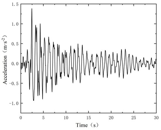
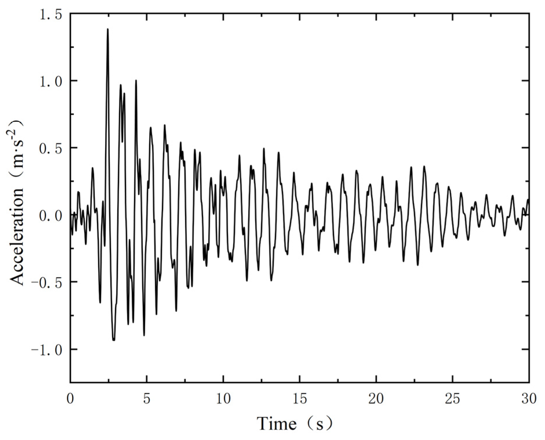
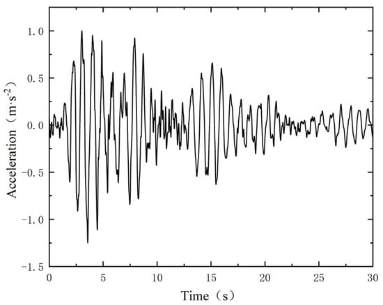
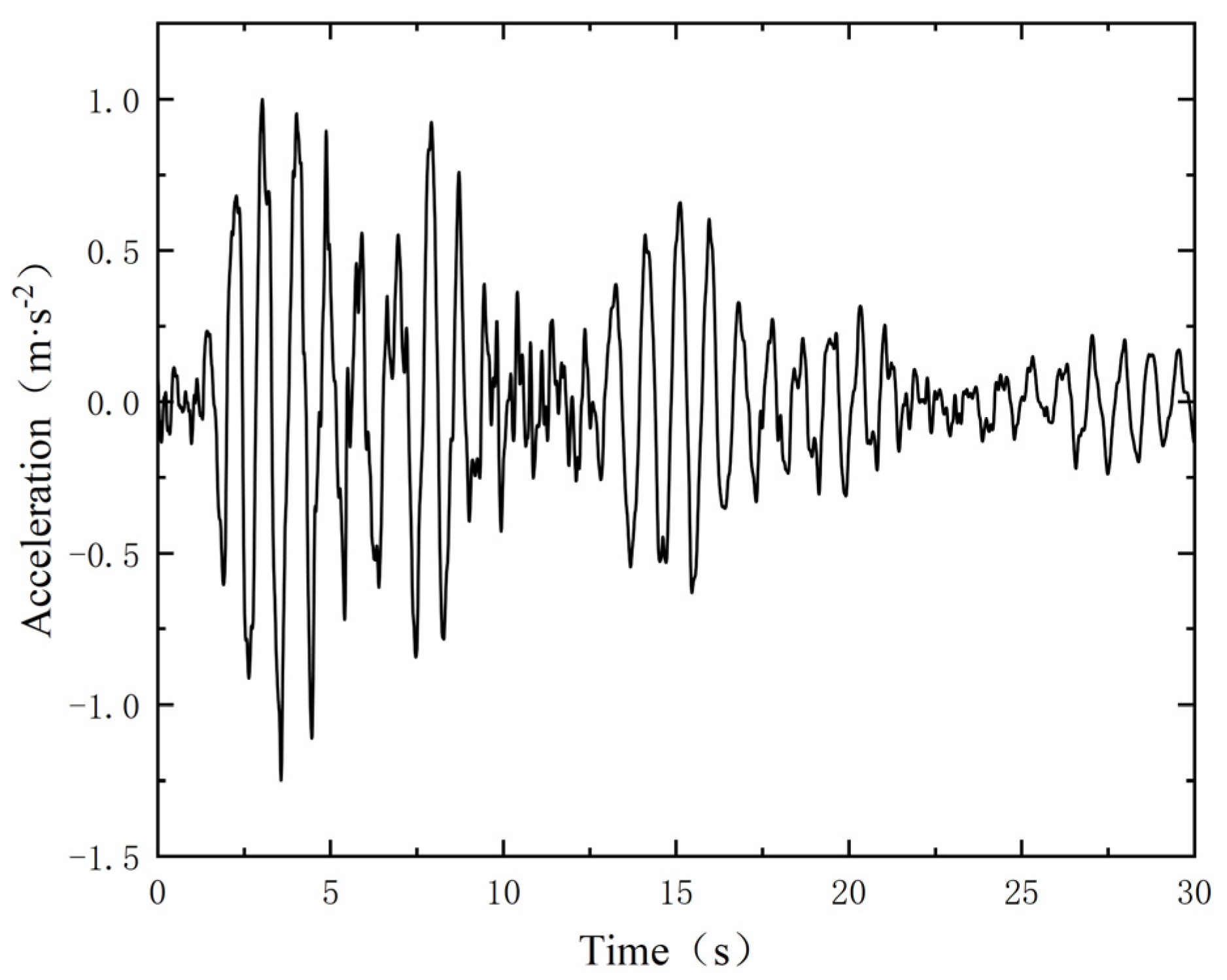
This paper adopts the Peak Ground Acceleration (PGA) amplitude modulation method. The Code for Seismic Design of Buildings [49,50] issued by the Ministry of Housing and Urban-Rural Development specifies that the corresponding PGAs for intensities VI, VII, and VIII are 0.05 g, 0.10 g, and 0.20 g, respectively. There is a clear corresponding relationship between seismic intensity and the basic design seismic acceleration. In this paper, the amplitude of the selected original seismic wave record is linearly scaled to make its PGA reach the target value specified in the code. Ground motion parameters include the amplitude, frequency spectrum characteristics, and duration of the ground motion. Due to the lack of strong earthquake historical data in the waters near Hainan, the 16 April 2016 Kumamoto, Japan M7.3 earthquake was selected as the seismic load, with a focal depth of 12 km. Figure 1 and Figure 2 show the recorded acceleration waveforms of this earthquake.
Figure 1.
NS direction seismic wave.
Figure 2.
EW direction seismic wave.
During the production process of subsea Christmas trees and subsea wellheads, their corrosion rates are influenced by multiple factors, and corrosion rates vary for different materials. Internationally, corrosion rates (measured annually) are typically classified into three grades: Class I, completely corrosion-resistant materials, with corrosion loss less than 0.1 mm/a, such as certain high-performance stainless steels; Class II, still corrosion-resistant materials, with corrosion rates between 0.1–1.0 mm/a, such as certain common stainless steels; Class III, non-corrosion-resistant materials, with corrosion rates greater than 1.0 mm/a [50]. Research on the marine environment of the South China Sea shows significant variations in corrosion rates for different materials in different zones. The specific annual corrosion rates are as follows: atmospheric zone 0.0562–0.0781 mm/a, splash zone 0.3531–0.4351 mm/a, tidal zone 0.3070–0.3783 mm/a, full immersion zone 0.1535–0.1892 mm/a [51]. Therefore, the corrosion rate for steel above the mudline is set at 0.2 mm/a, and below the mudline at 0.1 mm/a. Calculated over a design life of 25 years, the wall thickness above the mudline decreases by 5 mm, and below the mudline by 2.5 mm.
This paper takes a well in the Lingshui area of the South China Sea as an example. Based on the CNOOC “South China Sea Deepwater Gas Development Research Meteorological and Hydrological Environmental Design Conditions Study” survey report, and referring to API RP 16Q, API RP 2RD, API RP 2A-WSD specifications and the “Offshore Drilling Manual” [47,52,53,54], the ocean current is taken as the 100-year return period non-typhoon bottom current velocity of 1.55 m/s. According to the geological survey and engineering drilling data of this well site, the soil parameters where the subsea Christmas tree-subsea wellhead system is located are shown in Table 1.
Table 1.
Shallow soil parameters for a well in the Hainan Lingshui area.
3. Simulation Model Establishment and Solution
Due to the complex structure of the subsea Christmas tree-wellhead system, especially the large volume, mass, and irregular shape of the subsea Christmas tree, simplification would significantly affect the system’s dynamic response, leading to large deviations in theoretical calculation results. Therefore, simulation methods are adopted to calculate the dynamic performance of the system under seismic loading.
3.1. Model Establishment
A three-dimensional finite element model was established using ABAQUS 2023 software. The Christmas tree was simplified as a combination of cuboid and cylinder structures. The wellhead system includes the high-pressure wellhead, low-pressure wellhead, and surface conductor. Three types of working conditions were designed:
- Seismic superposition condition: Ocean current + Earthquake (Intensity V–VIII);
- Corrosion superposition condition: Ocean current + 25-year corrosion + Earthquake;
- Parametric analysis: Wellhead mudline height 1–7 m.
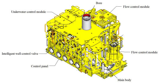
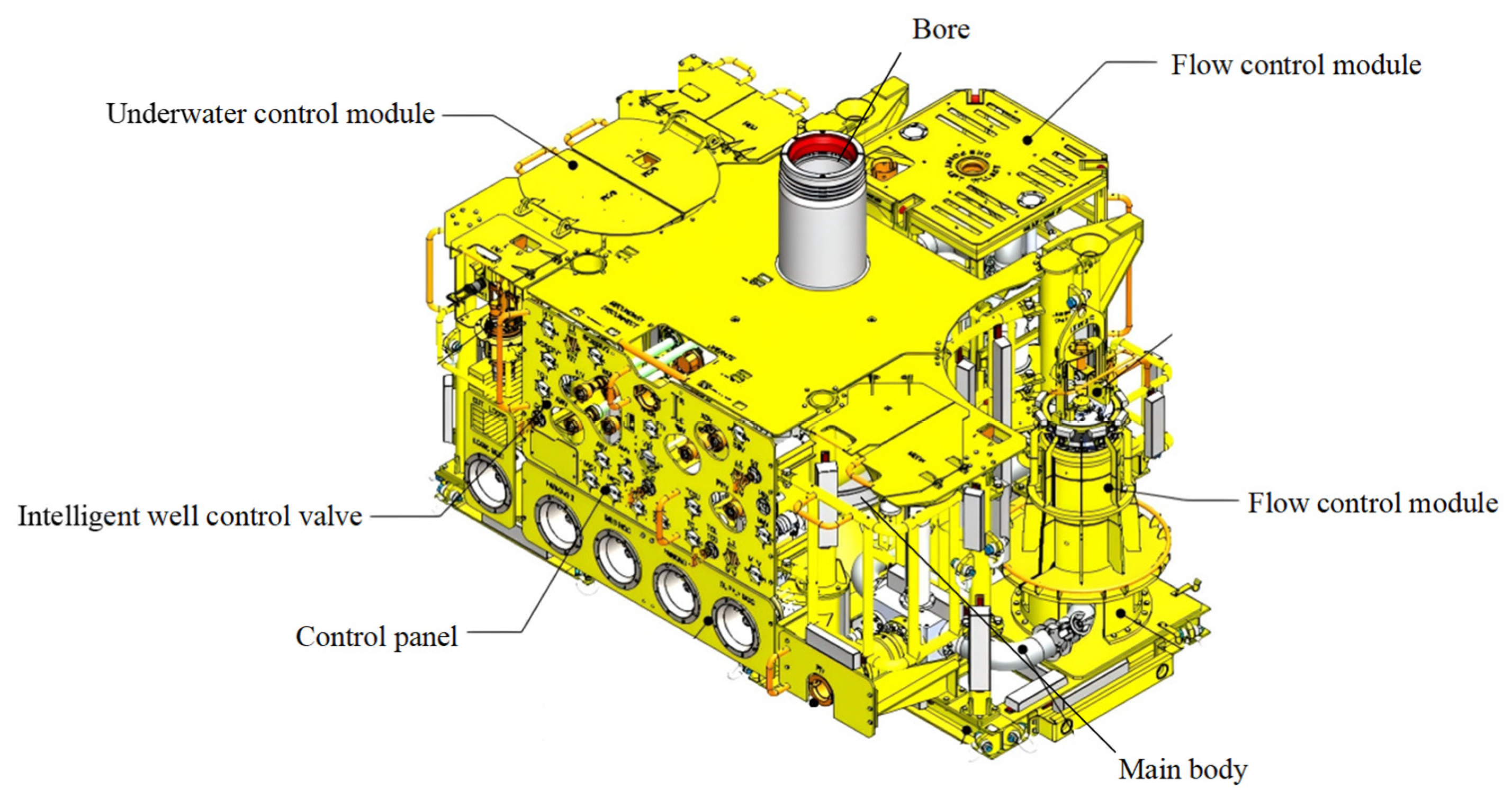
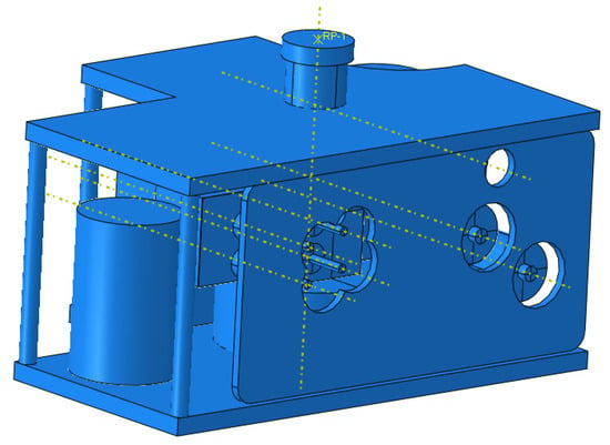
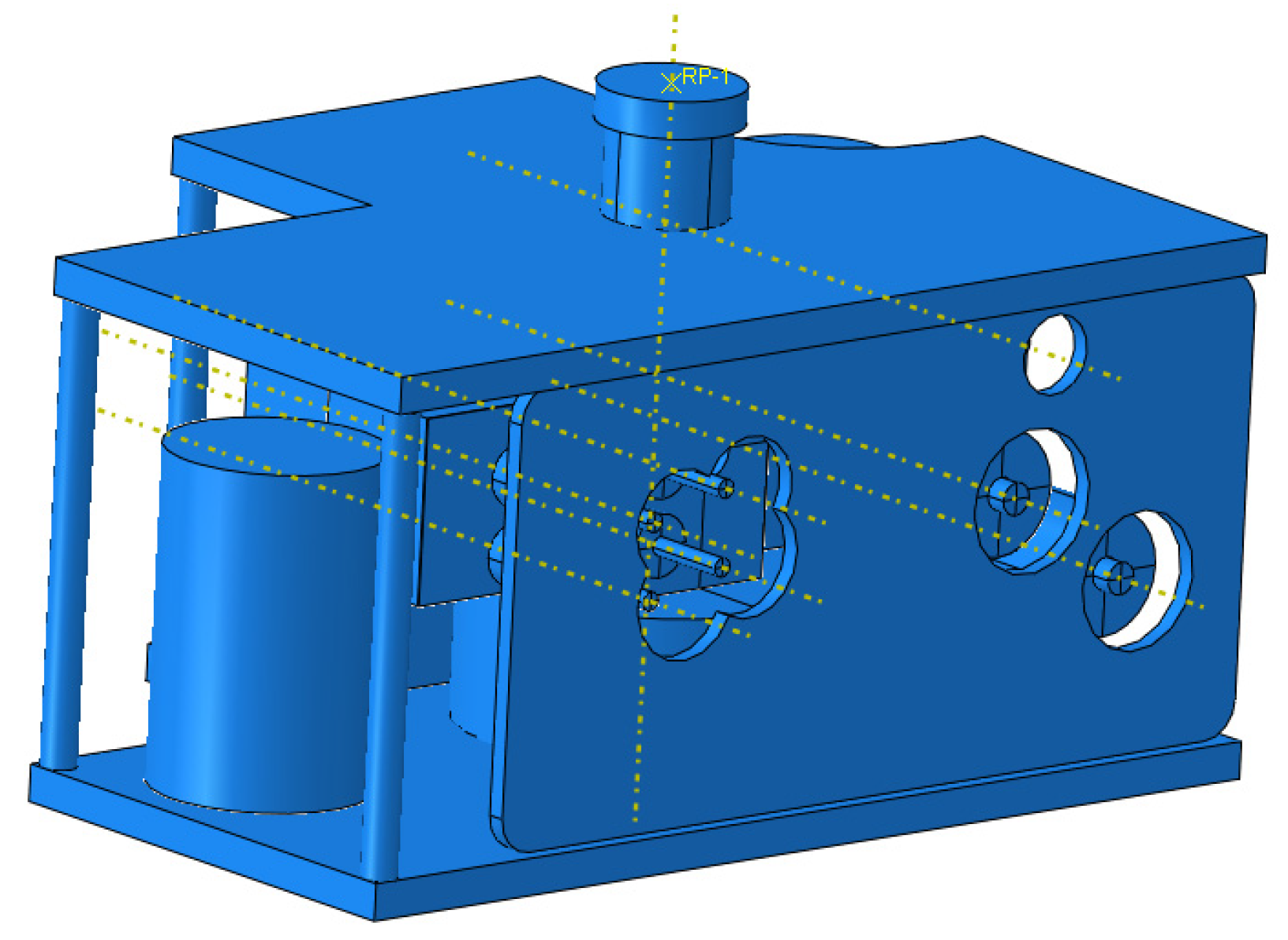
The subsea Christmas tree uses the structure of a well in the Lingshui area of the South China Sea, as shown in Figure 3. It mainly consists of flow control modules, subsea control modules, choke valves, the Christmas tree body, operation panels, bores, and numerous control valves. The structure is complex and difficult to model for mechanical analysis in finite element software. Consequently, considering the presence of the tree frame and protective devices, the subsea tree is appropriately simplified as shown in Figure 4 to facilitate the force analysis of the subsea tree–wellhead system.
Figure 3.
Structural diagram of the well in the Lingshui area, South China Sea.
Figure 4.
A simplified mechanical model of the subsea Christmas tree.
The component dimensions of the subsea Christmas tree-subsea wellhead system are shown in Table 2. The subsea Christmas tree is irregular, with a maximum height of 2.9 m, maximum length of 5.9 m, and maximum width of 4.4 m; the surface conductor penetration depth is 70 m, outer diameter 0.9144 m, the wall thickness of the two sections near the mudline is 0.038 m, other wall thickness is 0.0254 m, and the low-pressure wellhead mudline height is 3 m.
Table 2.
Dimensional data of subsea Christmas tree-wellhead system.
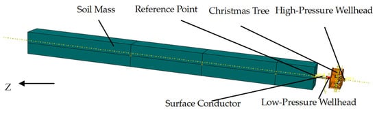
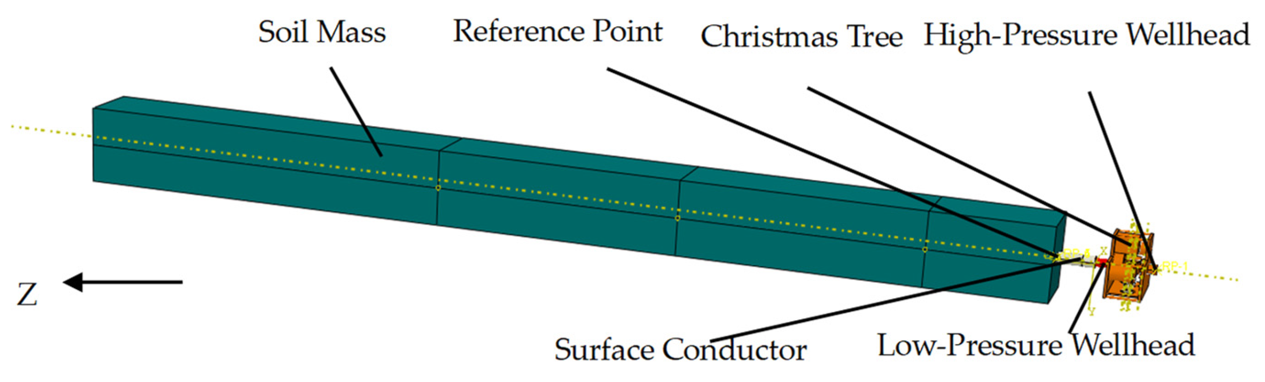
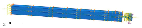
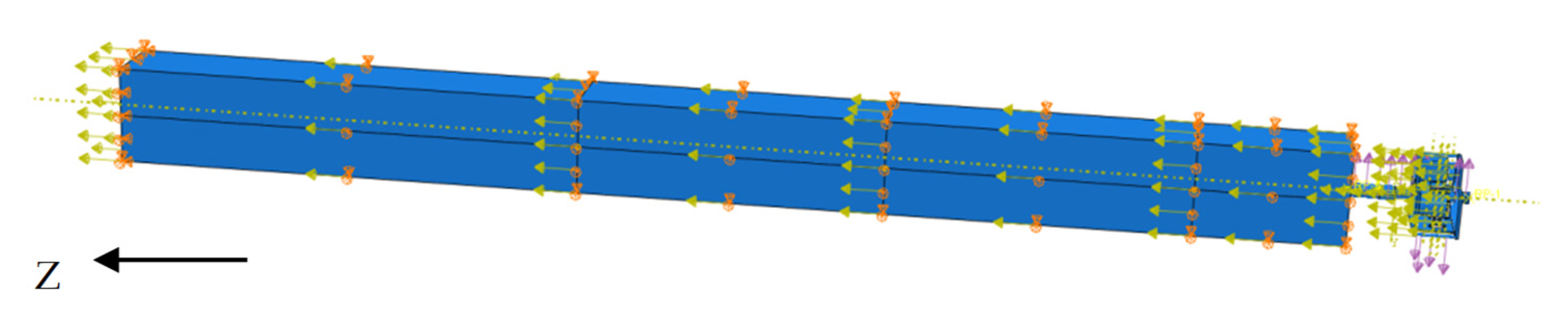
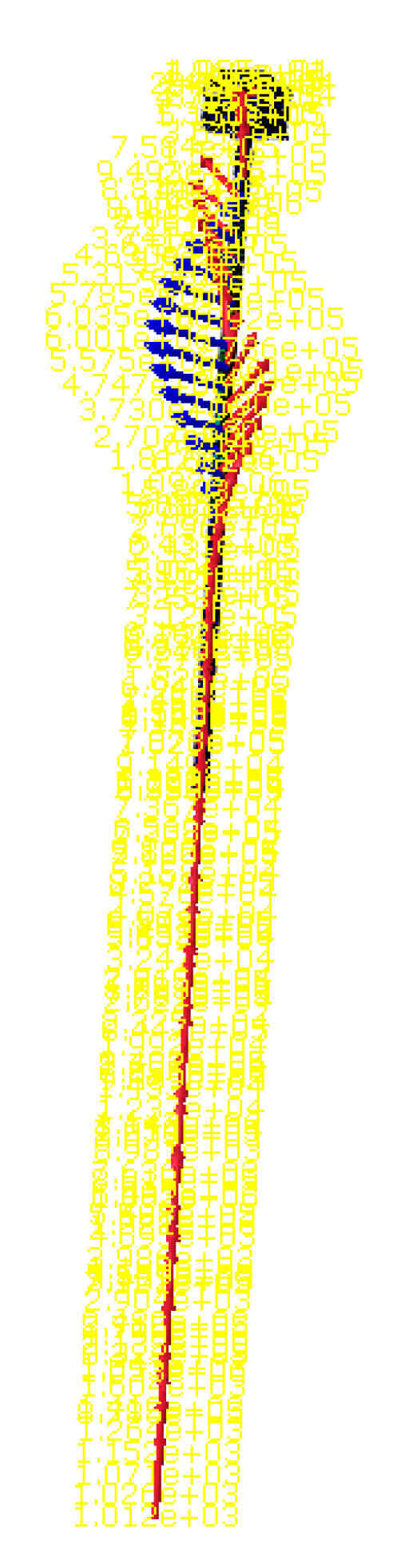
The finite element model established in ABAQUS 2023 is shown in Figure 5. The upper part of the model is the subsea Christmas tree, connected to the high-pressure wellhead. The high-pressure wellhead is tied to the low-pressure wellhead, and the lower part of the low-pressure wellhead is the surface conductor constrained in the soil. The model’s boundary conditions and loads are shown in Figure 6. The soil model uses a linear elastic model and a Mohr-Coulomb plastic model. To simulate the semi-infinite seabed and eliminate boundary effects, horizontal displacement constraints in the X and Y directions were imposed on the four lateral boundaries of the soil model, and displacement constraints in the Z direction were applied to the bottom surface of the model. Considering that the penetration depth of the surface conduit into the seabed reaches 70 m, the influence of seismic response at this depth on the structural stress near the mudline is negligible. Thus, the bottom of the conduit was set as a fully fixed end (constraining the displacements and rotational degrees of freedom in the X, Y, and Z directions). The outer surface of the conductor and the soil are set as surface-to-surface contact, normal behavior as hard contact, tangential friction coefficient as 0.3, and tangential behavior as the penalty function model. As shown in Figure 7, a reference point is set at the conductor cross-section at the mudline, and the cross-section is coupled to this point. Seismic acceleration is applied as a base motion fixed at the bottom boundary condition, acting on the mudline reference point. A uniformly distributed surface load representing the ocean current load is applied along the Y direction on the subsea Christmas tree and the high/low-pressure wellheads. Seismic load is input via time history analysis using the seismic waves, corresponding to intensity 7, with an equivalent period of 30 s.
Figure 5.
Subsea christmas tree-wellhead model.
Figure 6.
System loads and boundary conditions.
Figure 7.
System interactions and constraints.
The ABAQUS/Standard implicit solver was used for static and dynamic time history analysis. Addressing the material nonlinearity and geometric nonlinearity involved in the system, the Newton-Raphson iteration method was selected for solving the nonlinear equation system to ensure solution convergence and computational accuracy under complex contact and load conditions. During the solution process, the initial increment step was set, automatic time incrementation was enabled, and appropriate convergence tolerances were set to balance computational efficiency and stability.
3.2. Mesh Independence Analysis
The mesh was divided using hexahedral elements (C3D8R), with key areas refined to a mesh size of 0.1 m, as shown in Figure 8. The final model generated approximately 46,942 elements with good element quality. Furthermore, to verify the influence of mesh division on the calculation results, a mesh independence analysis was conducted. The results are shown in Table 3. When the number of elements exceeds 47,000, the displacement and stress values at keys nodes converge stably, with errors less than 1%, indicating that the current mesh division meets the accuracy requirements.
Figure 8.
Model mesh.
Table 3.
Mesh convergence study.
4. Results and Discussion
This study, by investigating factors such as different seismic intensities, corrosion effects, and mudline heights, found that under seismic intensity VII, the system’s stress and bending moment exceed allowable values. After corrosion, under seismic intensity VIII, the stress increased from 558.7 MPa to 574.7 MPa, an increase of 2.9%, indicating that corrosion further exacerbates failure risk. Calculation and analysis of the influence of wellhead mudline height on system stability show that its impact is relatively small. Based on this, the study proposes optimized design schemes, including selecting higher strength steel.
4.1. Analysis and Discussion of Multi-Factor Coupled Model Results
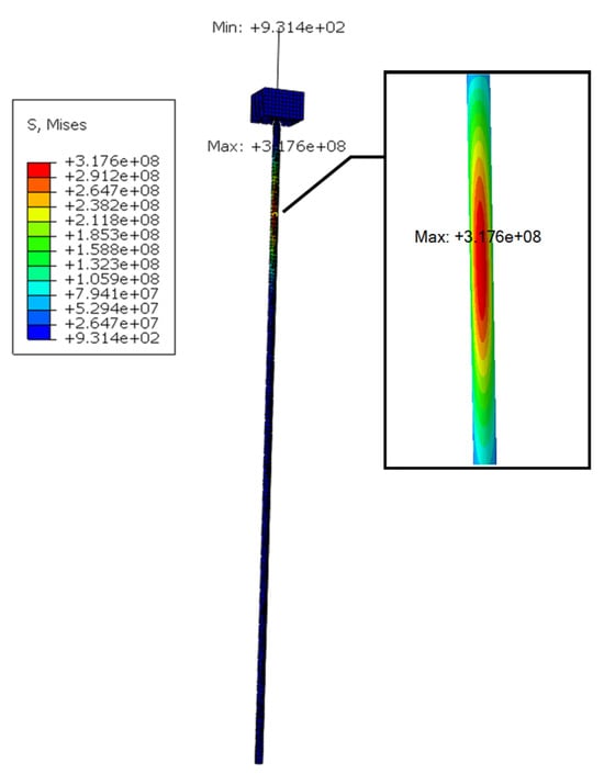
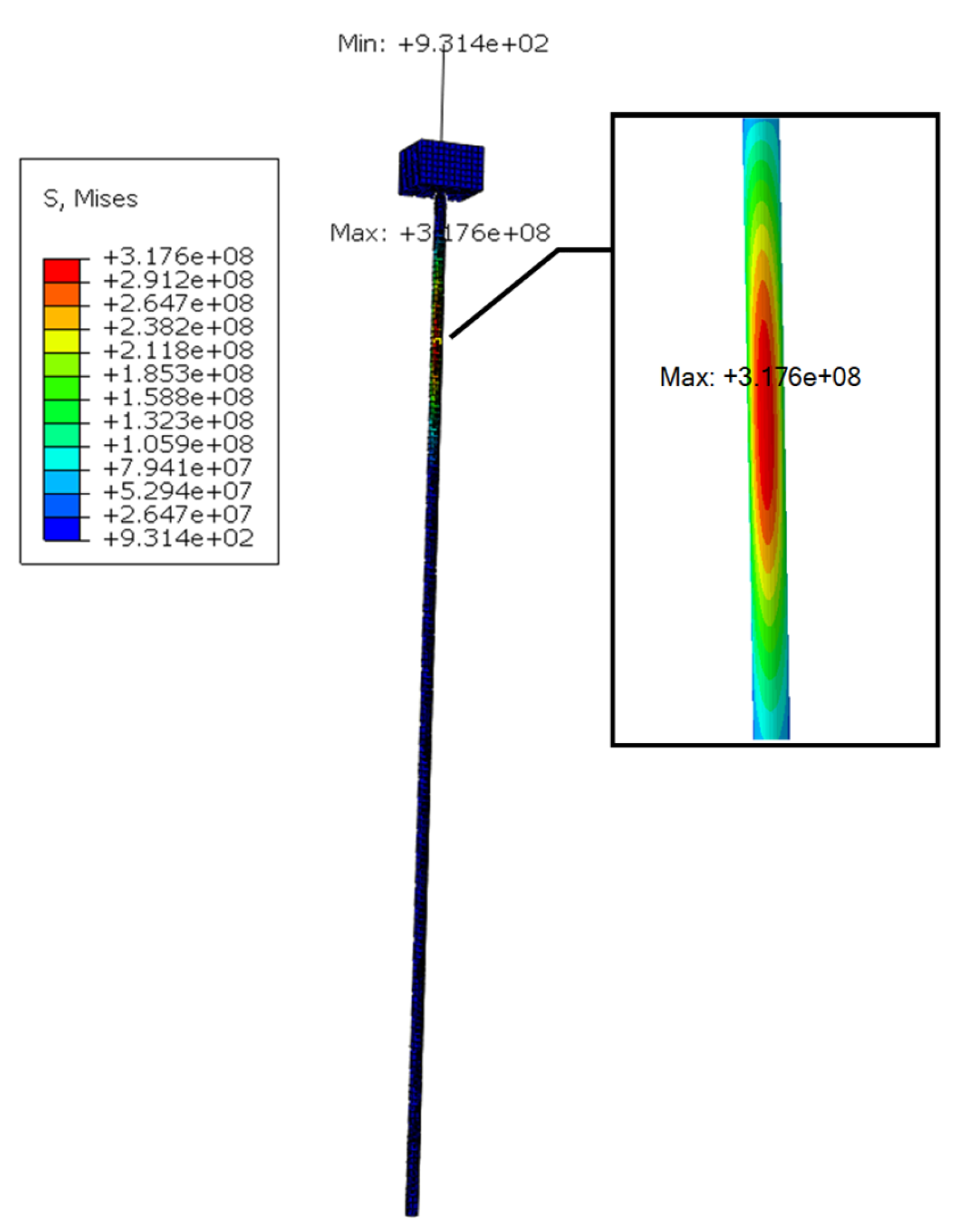
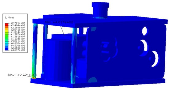
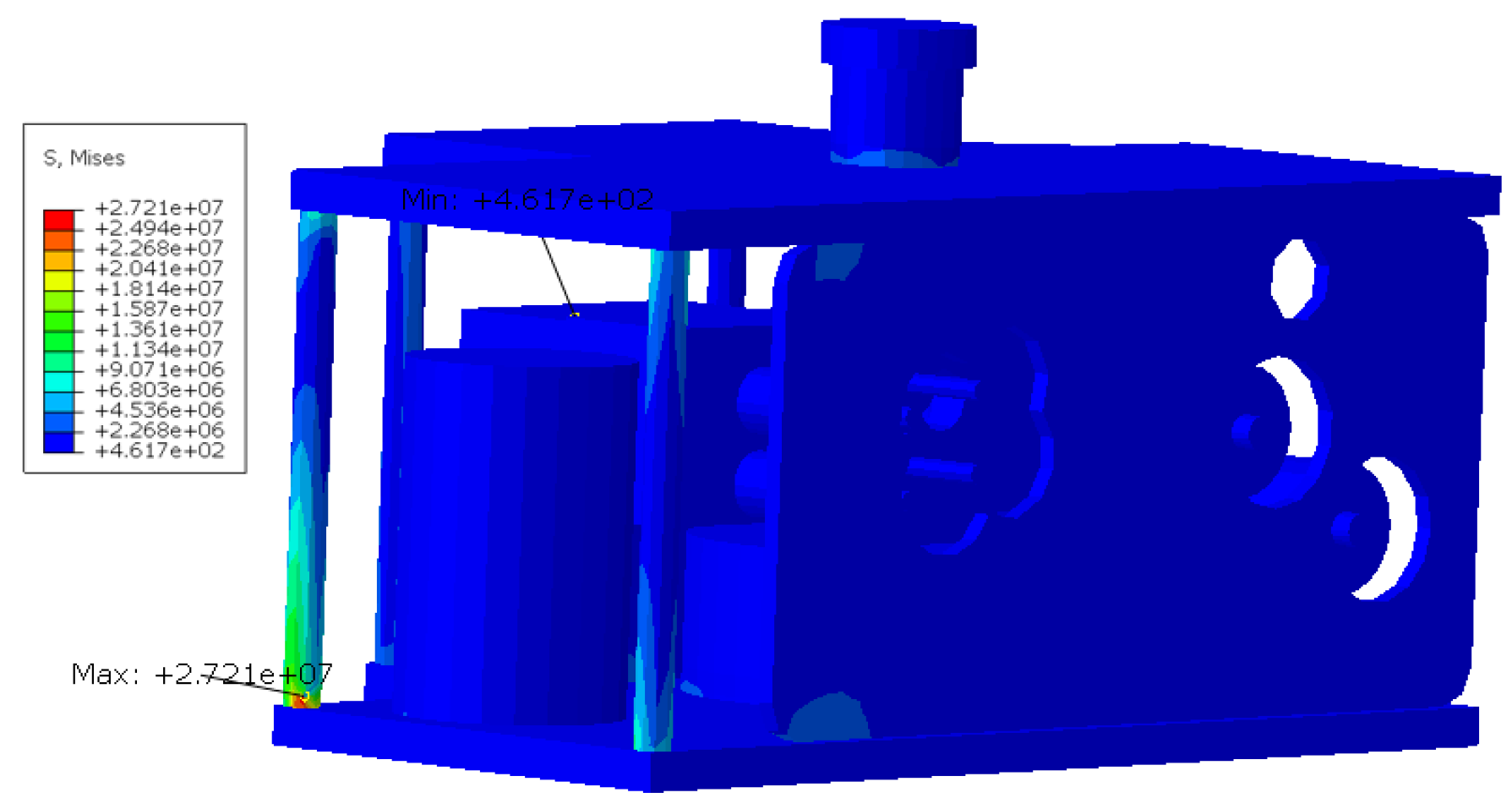
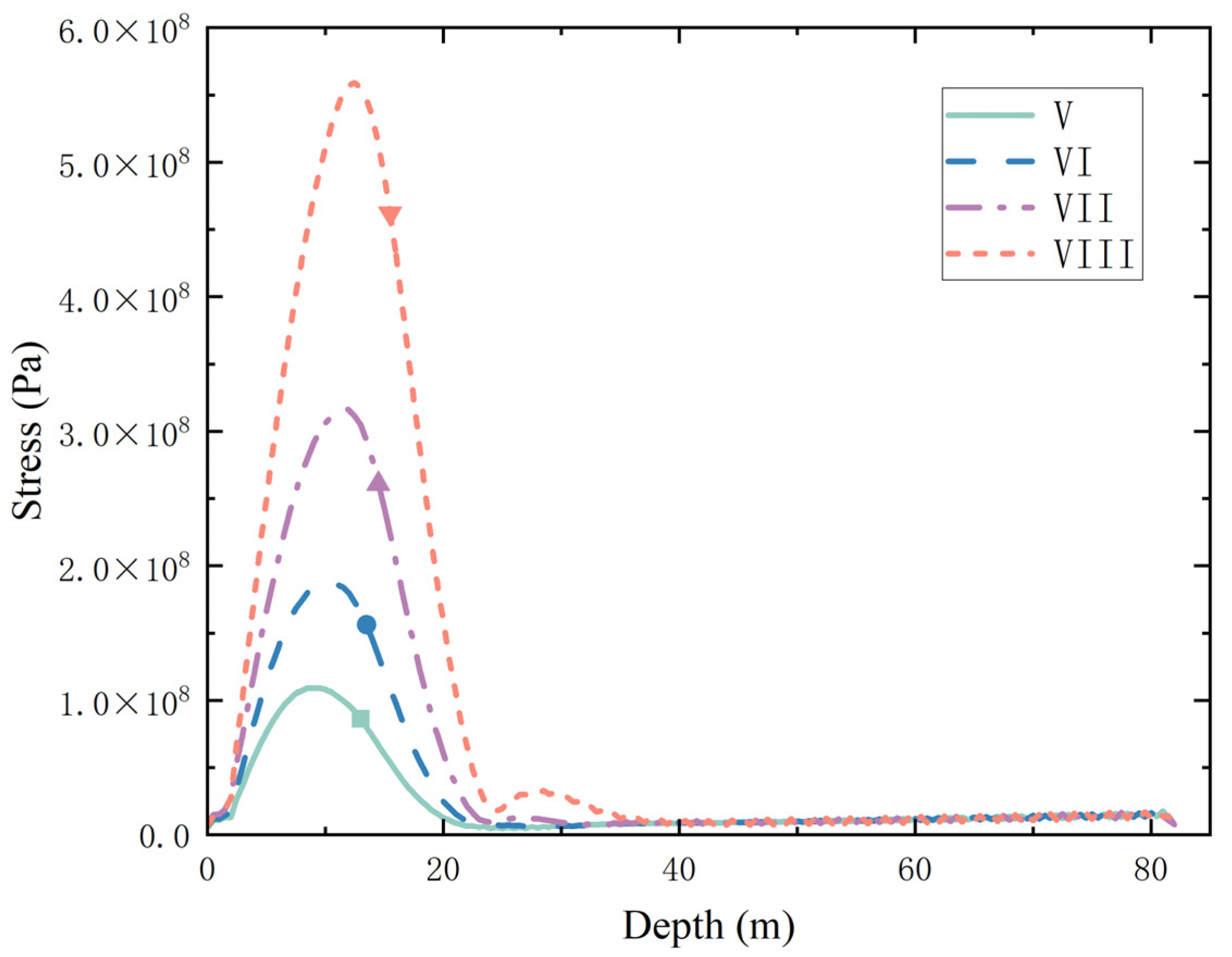
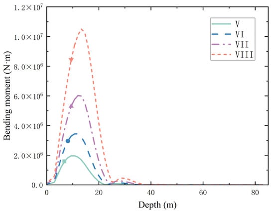
Under seismic loading and the 100-year return period ocean current, the forces on the subsea Christmas tree-subsea wellhead system are shown in Figure 9 and Figure 10. Figure 9 shows the system stress distribution. It can be seen that under seismic intensity VII, the stress along the surface conductor increases first and then decreases from top to bottom. The stress reaches a maximum value of 324.9 MPa at about 10 m below the mudline. This location corresponds precisely to the cross-section where the interaction moment between the conductor and the soil layers is greatest. The occurrence of the extreme value here is due, on one hand, to the combined action of ocean current and earthquake causing large shear displacement at the top of the conductor, and on the other hand, the transition of conductor stiffness at this depth from the sand layer to the softer clay layer, leading to stress concentration. Further downward, the stress decreases rapidly, leveling off at a low level around 25 m after entering the higher bearing capacity rock and soil layer. Figure 10 shows the system bending moment distribution. Under seismic intensity VII, the maximum bending moment is 6.02 MN·m, located on the surface conductor. The locations of maximum stress and bending moment are both around 10 m below the mudline, highly coincident, but the absolute position of the bending moment extreme is slightly lower, indicating that at this cross-section, the part farthest from the neutral axis (the outer side of the conductor) bears the maximum bending moment. A secondary peak occurs at the connection between the Christmas tree and the high-pressure wellhead, due to local stress concentration caused by the sudden change in structural cross-section under the combined action of inertial force and ocean current load. Throughout the entire length, the bending moment decreases from large to small with depth, dropping to a minimal value near 40 m and remaining almost constant, indicating that the consolidated soil below this depth sufficiently absorbs energy and attenuates most of the external load. The Christmas tree model under seismic intensity VIII is shown in Figure 11. The extreme stress value is 27.21 MPa, concentrated on the support columns, which is less than the allowable value for extreme environments, still in a safe state.
Figure 9.
System stress cloud diagram.
Figure 10.
System bending moment diagram.
Figure 11.
Christmas tree stress cloud diagram.
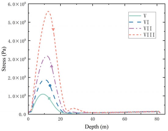
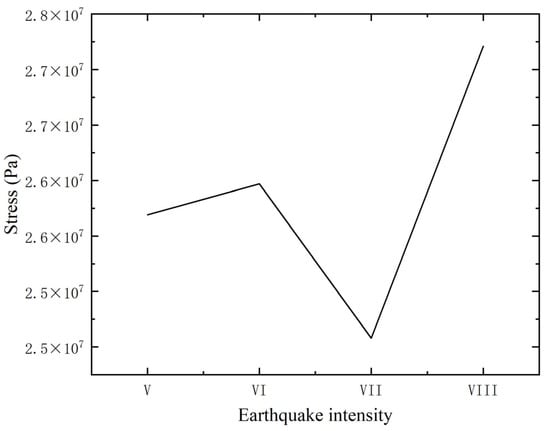
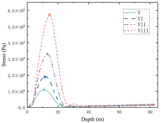
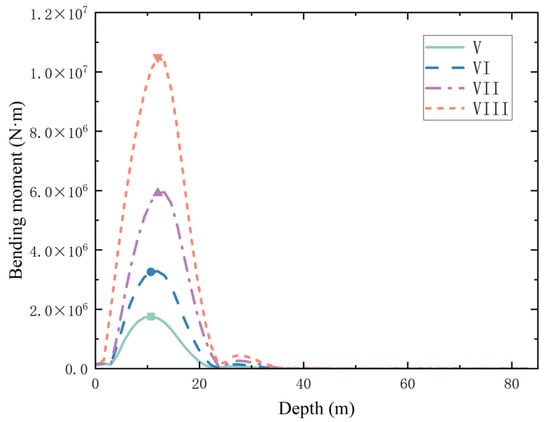
Figure 12 and Figure 13 show the stress and bending moment values of the subsea wellhead under different seismic intensities, respectively. When the low-pressure wellhead mudline height is 3 m, under ocean current force and seismic intensity V, the system’s maximum stress is 109.5 MPa, and the maximum bending moment is 1.96 MN·m, both far below the X56 steel allowable limits, with sufficient safety margin. As the seismic intensity increases, both the maximum stress and bending moment show a rapid upward trend. The extreme value locations are both on the surface conductor at 10–15 m below the mudline. This depth is exactly at the interface zone between the softer soil layer and the middle soil layer, where the soil damping is small, the shear modulus is low, and the conductor stiffness changes abruptly, making it easiest for the ocean current preload and seismic inertial forces to superimpose here, causing internal force concentration. The depth of the extreme point shifts downward with increasing seismic intensity. After the extreme point, the stress decreases rapidly, stabilizing at a lower level around 25 m. The bending moment decreases to a minimal value near 40 m and remains unchanged, indicating that the deep soil has good energy absorption and dissipation capacity for external loads. The position of the bending moment extreme is slightly lower than that of the stress extreme because stress reflects the strength concentration at the edge of the cross-section, while bending moment reflects the internal force distribution over the entire cross-section, resulting in a slight spatial deviation between them. Figure 14 shows the extreme stress values of the subsea Christmas tree under different intensities. Under seismic intensity VIII, the maximum stress on the Christmas tree is 27.21 MPa.
Figure 12.
Subsea wellhead stress distribution under different seismic loads.
Figure 13.
Subsea wellhead bending moment distribution under different seismic loads.
Figure 14.
Christmas tree stress distribution under different seismic loads.
4.2. Analysis of Corrosion Effects Under Seismic Loading
The combined effect of corrosion and seismic loading was analyzed for a field development life of 25 years. The wellhead mudline height was set at 3 m. A corrosion rate of 0.2 mm/a was applied above the mudline, causing a 5 mm reduction in wall thickness. Conversely, a rate of 0.1 mm/a was applied below the mudline, causing a 2.5 mm reduction. When establishing the finite element model(FEM) for the corrosion condition, based on the initial geometric dimensions in Table 2, the wall thickness of all components above the mudline is uniformly reduced by 5 mm, and the wall thickness of the surface conductor below the mudline is uniformly reduced by 2.5 mm, so as to accurately simulate the corrosion loss of materials through changes in the geometric model. As shown in Figure 15 and Figure 16, under seismic intensity VIII, the stress distribution still maintains the characteristic “first increase then decrease” curve, but the extreme value is significantly elevated. The stress extreme still occurs at the soft-hard soil transition zone, approximately 10 m below the mudline. In this region, soil damping is low, and the shear modulus changes abruptly. Additionally, the section modulus decreases due to corrosion. Consequently, the maximum stress increases from 558.7 MPa to 574.7 MPa, representing a rise of about 2.9%. This phenomenon indicates that the accumulation of corrosion during long-term service weakens the structural load-bearing capacity, especially under strong seismic loads, significantly increasing the equipment’s failure risk. Therefore, in practical engineering design, structural protection and material selection against corrosion effects should be a focus.
Figure 15.
Stress distribution of corroded subsea wellhead under seismic load.
Figure 16.
Bending moment distribution of corroded subsea wellhead under different seismic loads.
4.3. Analysis and Discussion of the Influence of Wellhead Mudline Height Under Seismic Loading
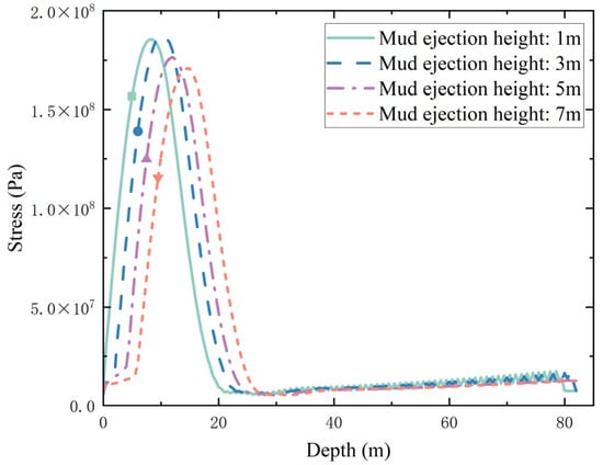
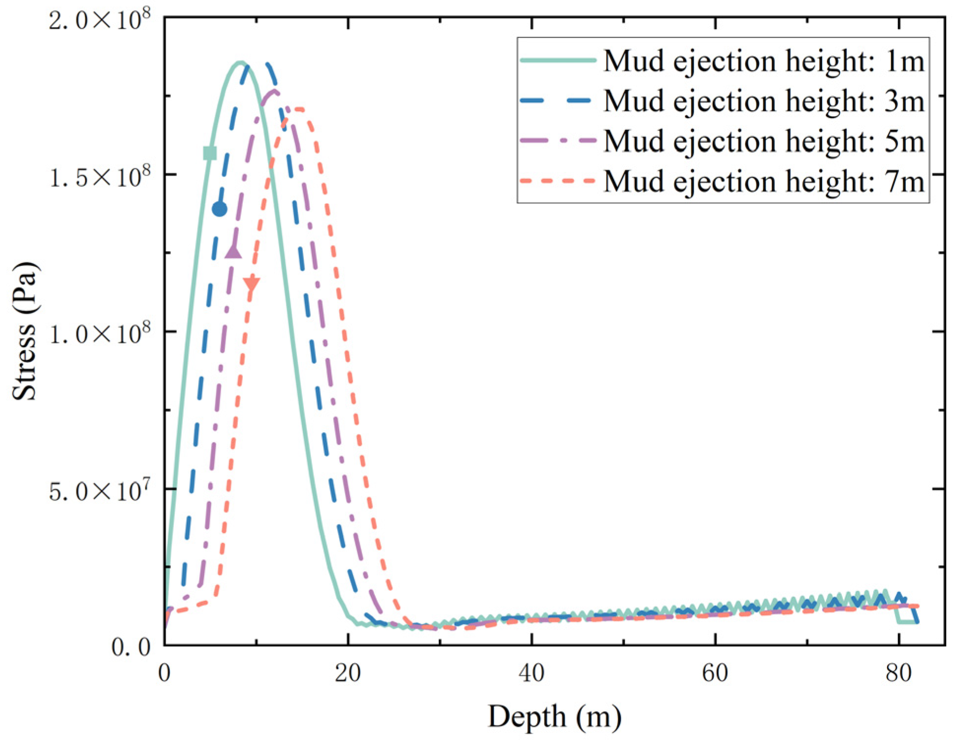
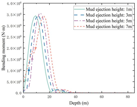
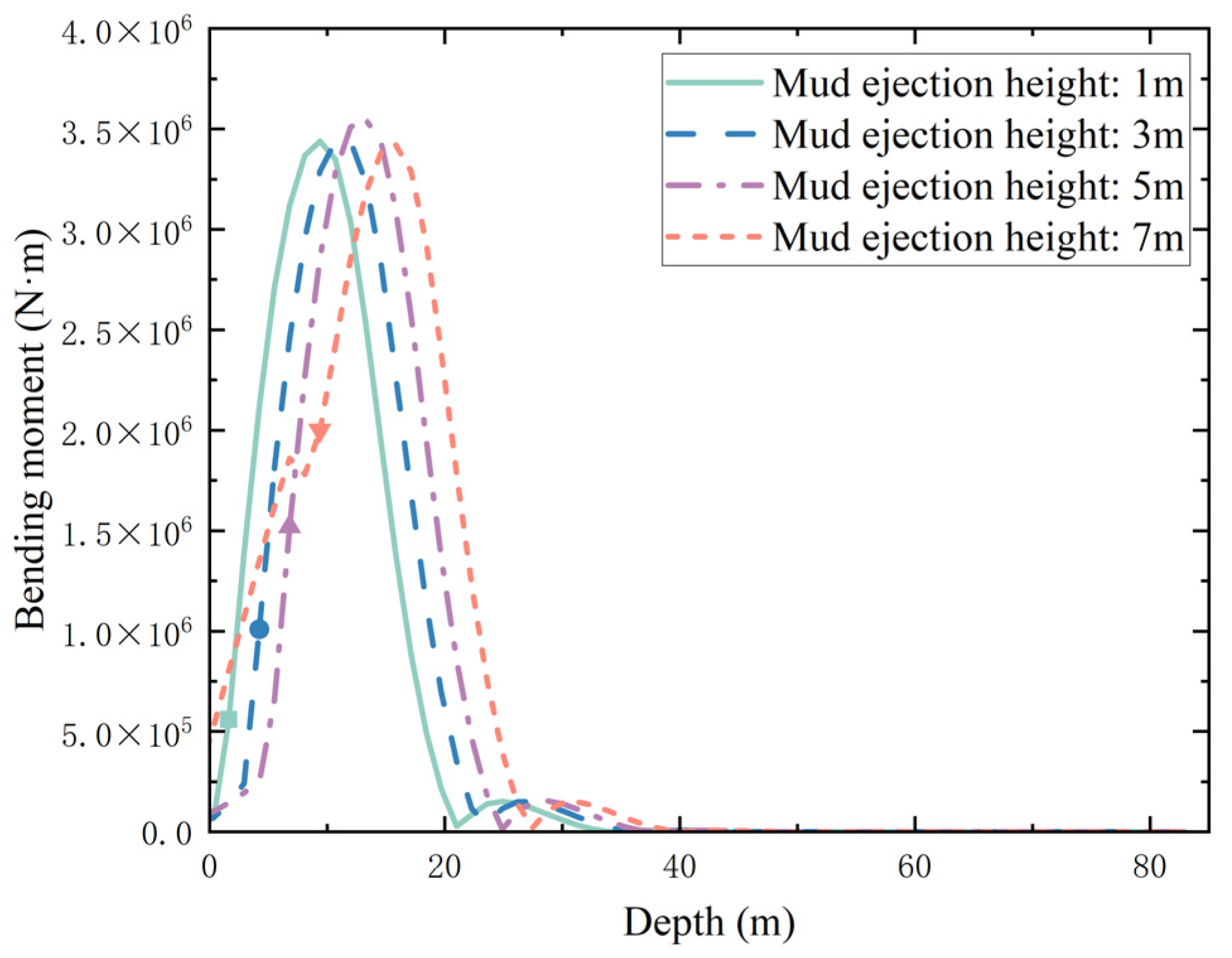
To evaluate the impact of the subsea wellhead installation height on system performance, the subsea Christmas tree–wellhead system was subjected to seismic intensity level VI loads under once-in-a-century current forces. The mechanical conditions of the system were calculated for mudline clearances of 1 m, 3 m, 5 m, and 7 m. The calculation results are shown in Figure 17 and Figure 18. When the mudline clearance increased from 1 m to 3 m, the extreme values changed only slightly. However, when the mudline clearance further increased to 5 m and 7 m, the extreme stresses actually decreased. This phenomenon can be attributed to two main reasons: First, as the mudline clearance increases, the free cantilever length of the conductor becomes longer. Although this increases the lever arm, the hydrodynamic load area also increases, and the resultant center of the hydrodynamic load gradually moves upward. As a result, beyond a certain height, the combined effect of flow velocity and lever arm peaks then declines. Second, the current velocity exhibits a vertical profile distribution: it is lowest within the boundary layer below the mudline, increases upward, and then slightly decreases near the sea surface due to wave action. Consequently, the lateral drag force on the portion excessively high above the mudline is actually reduced. The stress and bending moment in the region above the mudline increase slightly with the installation height but remain at a relatively low level overall. In contrast, the maximum stress and bending moment below the mudline do not change significantly. The envelopment and damping effect of the deep soil on the conductor play a dominant role, and their capacity to absorb and dissipate external loads remains approximately constant across different installation heights. This indicates that variations in wellhead installation height have a relatively limited impact on the overall stability of the system.
Figure 17.
Subsea stress distribution under different wellhead mudline heights and seismic loads.
Figure 18.
System bending moment distribution under different wellhead mudline heights and seismic loads.
4.4. Strength Verification and Risk Analysis
As critical components located above the mudline, the subsea Christmas tree and wellhead are subjected to complex loads. Therefore, high-strength steels are selected for their construction. The main body of the subsea Christmas tree utilizes F22 forged steel with a yield strength of 620 MPa, while the tree framework is made of Q345B material having a yield strength of 345 MPa. The high-pressure and low-pressure wellheads employ 8630 grade steel with a yield strength of 550 MPa. The surface conductor typically uses X56 grade pipeline steel with a yield strength of 386 MPa [55].
Based on the calculation results, the maximum stress in the subsea Christmas tree under seismic loading is located on the framework support columns and remains below 30 MPa, indicating a relatively low risk. Starting from the high-pressure wellhead, the system stress and bending moment increase rapidly, with the extreme values occurring near 10 m below the mudline. Overall, the forces above the mudline are relatively small, and the strength of the 8630 grade steel is significantly higher than that of X56 steel. Consequently, risk analysis needs to be performed only for the surface conductor.
The surface conductor is designed according to the CNOOC specification “Design and Operation Specification for Offshore Development Well Riser Conductor” [56]. The allowable stress is selected based on Table 4, where σs is the steel yield strength in MPa. Given that the surface conductor withstands severe conditions such as seismic loads, a safety factor of 1.25 should be applied. For X56 steel with a yield strength of 386 MPa, the extreme environment allowable stress for the surface conductor is 308.8 MPa, and the allowable bending moment is 4.61 MN·m.
Table 4.
Allowable stress values for riser conductor.
Under the 100-year return period ocean current and seismic load, the forces on the surface conductor are shown in Table 5: Below seismic intensity VII, the system’s extreme stress and bending moment values are both less than the extreme environment allowable values, indicating a safe state. At seismic intensity VII and above, the system’s maximum stress and bending moment both exceed the extreme environment allowable values, and safety cannot be guaranteed.
Table 5.
Surface conductor forces under 100-year current and different seismic loads.
The forces on the corroded subsea wellhead under the 100-year return period ocean current and seismic load are shown in Table 6. Compared with the allowable stress and bending moment values under extreme environments, below seismic intensity VII, the system remains in a safe state; at seismic intensity VII, the system’s maximum bending moment is 6.06 MN·m, exceeding the allowable bending moment of 4.61 MN·m. Therefore, at seismic intensity VII and above, the subsea wellhead has a risk of failure, and safety cannot be guaranteed.
Table 6.
Corroded subsea wellhead forces under 100-year current and different seismic loads.
This paper aims to verify the elastic bearing capacity of the system under extreme working conditions. Therefore, a linear elastic material model was adopted for steel in the finite element analysis. Under this model assumption, when the calculated stress exceeds the material yield strength, this value does not represent the actual physical stress of the material, but serves as a theoretical indicator for determining that the structure enters the plastic zone and undergoes strength failure.
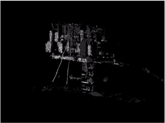
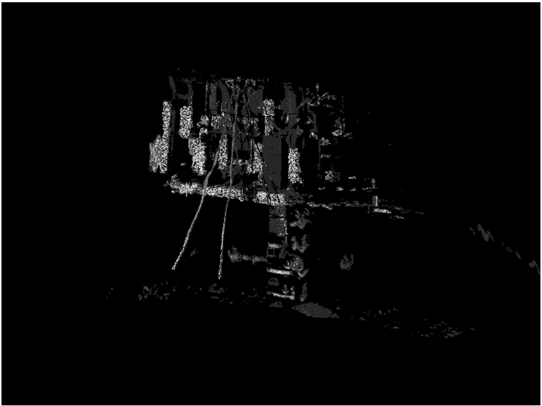
Since its completion in 2020, the well in the Lingshui area of the South China Sea has experienced 45 earthquakes around Hainan [57], including three events of magnitude 3.0–4.0, one event of magnitude 4.0–5.0, and one event of magnitude 5.0. The subsea tree–wellhead system has exhibited stable performance. Following the scientific exploration by the “Deep Sea Warrior” manned submersible in September 2022 and routine ROV inspections, no significant inclination or oil and gas leakage was detected. Figure 19 presents the deep-sea optical 3D imaging scan of the subsea tree–wellhead system, which validates the accuracy of the calculation results in this paper.
Figure 19.
Deep sea optical 3D imaging scan of subsea Christmas tree-wellhead system.
In summary, the multi-factor coupled analysis model proposed in this paper can effectively calculate the mechanical characteristics of the subsea Christmas tree-wellhead system under extreme seismic conditions in deepwater complex environments. It comprehensively calculates the force characteristics of the system under the superposition of ocean currents, earthquakes, and corrosion, and evaluates the impact of subsea wellhead mudline height on system forces. The research results provide a key theoretical basis for the design optimization and long-term service safety assurance of subsea Christmas tree-subsea wellhead systems, possessing significant engineering application value.
5. Conclusions and Suggestions
Based on Hamilton’s principle, this paper establishes a dynamic theoretical model for the subsea Christmas tree-wellhead system. Comprehensively considering the coupling effects of multiple factors such as ocean currents, earthquakes, and corrosion, the mechanical characteristics of the system under extreme seismic conditions in deepwater complex environments are investigated. The influences of corrosion effects and wellhead mudline height on the system forces are analyzed, strength verification and risk analysis are conducted, and optimized design recommendations are proposed. The main conclusions are as follows:
(1) Under the combined action of ocean current forces and earthquakes, both the stress and bending moment of the subsea wellhead exhibit a “bell-shaped” distribution along the depth, first increasing and then decreasing, with extreme values concentrated in the interval of 10–15 m below the mudline. Taking intensity VII as an example, the maximum stress at the conductor reaches 324.9 MPa, and the maximum bending moment is 6.02 MN·m. As the depth increases, the stress stabilizes at a relatively low level around 25 m, and the bending moment approaches zero and remains stable around 40 m, fully demonstrating the significant energy absorption and dissipation capacity of the deep soil for external loads. The extreme stress values of the subsea Christmas tree are concentrated on the support columns, all below the allowable values for extreme environments, indicating it remains in a safe state.
(2) Seismic intensity has an exponential amplification effect on the system’s extreme values. When the intensity increases from level V to level VII, the extreme stress jumps from 109.5 MPa to 324.9 MPa, an increase of approximately 197%; the extreme bending moment increases from 1.96 MN·m to 6.02 MN·m, an increase of approximately 207%. Concurrently, the location of the extreme value cross-section shifts downward by about 2–3 m, reflecting the overall lateral displacement of the system and the downward shift of the inertial load center under strong seismic action.
(3) Corrosion effects weaken the cross-sectional load-bearing capacity. Calculated for a 25-year service life, under intensity VIII seismic conditions, the extreme stress increases from 558.7 MPa to 574.7 MPa, an increase of 2.9%. This indicates that corrosion effects influence the force characteristics of the surface conductor and may reduce the system’s capacity to withstand seismic intensity.
(4) The wellhead mudline height has limited influence on deep structural forces, but causes the extreme values in the upper section to follow a pattern of initial increase followed by decrease. As the mudline height increases from 1 m to 3 m, the extreme stress shows minimal change. When the height further increases to 5 m and 7 m, the extreme stress demonstrates a declining trend. In contrast, stress and bending moment fluctuations in the zone below the mudline remain insignificant, indicating that the free-end height above the mud surface within a certain range has negligible impact on the mechanical response of the subsea Christmas tree-wellhead system.
(5) Although the calculation method in this paper achieves satisfactory results, it neglects the degree of functional failure of the equipment under extreme seismic conditions and does not consider the weakening effect of seismic dynamic loads on the soil. Subsequent research could focus on risk analysis of the functions of subsea Christmas trees and wellheads under extreme seismic conditions to clarify the system’s functional reliability under such scenarios. Introducing a soil weakening model under cyclic loading, combined with multi-directional random seismic time history analysis, could be used to evaluate the system’s mechanical stability under extreme conditions.
Author Contributions
Conceptualization, G.C. and S.L.; Methodology, X.Z. (Xuezhan Zhao), G.C. and S.L.; Software, X.Z. (Xuezhan Zhao), G.C. and X.Z. (Xingpeng Zhang); Validation, X.Z. (Xuezhan Zhao), G.C., S.L., Y.M., X.Z. (Xingpeng Zhang), Q.X., X.C. and B.G.; Formal analysis, Y.H. and B.G.; Investigation, X.Z. (Xuezhan Zhao), G.C. and X.C.; Resources, G.C., Y.H., Z.H. and Y.M.; Data curation, X.Z. (Xuezhan Zhao), Y.H., Z.H., Y.M., X.Z. (Xingpeng Zhang) and Q.X.; Writing—original draft, X.Z. (Xuezhan Zhao); Writing—review and editing, X.Z. (Xuezhan Zhao) and S.L.; Visualization, X.Z. (Xuezhan Zhao), G.C., Y.H., Z.H., X.Z. (Xingpeng Zhang) and Q.X.; Supervision, Y.H., S.L., Z.H., Y.M. and B.G.; Project administration, X.Z. (Xuezhan Zhao), G.C., Y.H., S.L., Z.H. and Y.M.; Funding acquisition, B.G. All authors have read and agreed to the published version of the manuscript.
Funding
This research was funded by National Key Research and Development Program of China, grant number 2022YFC2806100; National Natural Science Foundation of China, grant number U22B20126 and 52504012.
Data Availability Statement
The original contributions presented in this study are included in the article. Further inquiries can be directed to the corresponding author.
Conflicts of Interest
Author Xuezhan Zhao and Yi Hong were employed by the company CNOOC Ltd. Author Zhiqiang Hu was employed by the company Sinopec Research Institute of Petroleum Engineering Co., Ltd. The remaining authors declare that the research was conducted in the absence of any commercial or financial relationships that could be construed as a potential conflict of interest.
References
- China National Petroleum Corporation Economic and Technical Research Institute. 2024 Domestic and International Oil and Gas Industry Development Report; China National Petroleum Corporation Economic and Technical Research Institute: Beijing, China, 2025. [Google Scholar]
- BP plc. BP World Energy Outlook; BP plc: London, UK, 2024. [Google Scholar]
- IHS Markit. Global Offshore Oil and Gas Exploration and Development Characteristics and Trend Analysis Report; IHS Markit: London, UK, 2024. [Google Scholar]
- Research and Markets. Global Oil and Gas Discoveries Review, 2024; Research and Markets: Dublin, Ireland, 2024. [Google Scholar]
- Yang, J.; Li, W.L.; Hu, Z.Q.; Yin, Q.S.; Li, S.Z. Research progress on subsea wellhead stability in deepwater drilling. China Offshore Oil Gas 2020, 32, 124–130. [Google Scholar]
- Wu, Y.; Xing, X.S.; Pang, Z.Y.; Huang, Z.X. Research and application of key technologies of integrated drilling and completion for offshore exploration and development. China Offshore Oil Gas 2022, 34, 128–133. [Google Scholar] [CrossRef]
- Wang, L.; Yang, J.; Li, L.L.; Hu, Z.Q.; Ke, K.; Zang, Y.B.; Sun, T. Study on wellhead stability during drilling of deepwater hydrate-bearing formations. Chin. J. Geotech. Eng. 2022, 44, 2312–2318. [Google Scholar] [CrossRef]
- Lin, Z.Q.; Wang, W.X.; Liu, H.H.; Zhang, X.X.; Zhang, T.W. Analysis of causes of surface conductor sinking and wellhead stability in an overseas deepwater well. Chem. Ind. Manag. 2022, 1, 113–116. [Google Scholar]
- Li, L.L.; Yang, J.; Lu, B.P.; Ke, K.; Wang, L.; Chen, K.J. Study on formation subsidence and wellhead stability during trial production of deepwater hydrates. Pet. Drill. Tech. 2020, 48, 61–68. [Google Scholar]
- Yang, J. Calculation method of surface conductor setting depth in deepwater oil and gas wells. Acta Pet. Sin. 2019, 40, 1396–1406. [Google Scholar] [CrossRef]
- Wu, Y.; Yang, J.; Li, C.; Wei, Q.; Yang, L.C.; Huang, Y.; Gu, C.W.; Yao, M.J. Mechanical performance analysis of subsea wellhead based on ANSYS. Pet. Mach. 2011, 39, 35–37. [Google Scholar]
- Yang, J.; Zhang, M.H.; Zhang, W.G.; Chen, B.; Yan, D.; Li, L.; Tong, G. Efficient “three-in-one” operation mode for shallow drilling in deepwater. J. Pet. Sci. 2025, 46, 599–608. [Google Scholar]
- Zhou, B.; Yang, J.; Liu, Z.L.; Luo, J.; Ye, J.; Chen, B.; Liu, S.; Zhou, J. Design of conductor soaking time in deepwater drilling. Pet. Explor. Dev. 2014, 41, 257–261. [Google Scholar] [CrossRef] [Scilit]
- Zhou, B.; Yang, J.; Xu, Y.J.; Liu, Z.; Luo, J.; Ye, J.; Liu, S.J.; Zhou, J.; Wu, Y. Experimental research on structural casing soaking time in deepwater drilling. In Proceedings of the SPE Deepwater Drilling and Completions Conference, Galveston, TX, USA, 10–11 September 2014. SPE: D021S015R003. [Google Scholar]
- Zhou, B.; Yang, J.; Zhou, J.L.; Liu, Z.L.; Yang, J.G. Study on the influence of deepwater jet disturbance on the bearing capacity of surface conductor. China Offshore Oil Gas 2016, 28, 98–102. [Google Scholar]
- Guan, Z.C.; Su, K.H.; Su, Y.N. Analysis of lateral bearing capacity of conductor and surface casing in deepwater drilling. J. Pet. Sci. 2009, 30, 285–290. [Google Scholar]
- Guan, Z.C.; Su, K.H.; Qing, C.; Su, Y. Numerical simulation of subsea wellhead stability for deepwater drilling. In Proceedings of the SPE International Oil and Gas Conference and Exhibition in China, Beijing, China, 8–10 June 2010. SPE: SPE-130823-MS. [Google Scholar]
- Su, K.H.; Guan, Z.C.; Shi, L. Dynamic response of the casing string in seabed soil for deepwater drilling. Appl. Mech. Mater. 2012, 170–173, 2217–2221. [Google Scholar] [CrossRef] [Scilit]
- Su, K.H. Research status of coupling interaction between casing string and shallow seabed soft soil in deepwater drilling. J. Chongqing Univ. Sci. Technol. (Nat. Sci. Ed.) 2012, 14, 43–46. [Google Scholar]
- Su, K.H.; Guan, Z.C.; Long, Z.H. Influence of shallow seabed formation properties on wellhead stability in deepwater drilling. Pet. Drill. Prod. Technol. 2012, 34, 7–10. [Google Scholar]
- Su, K.H.; Yang, J.M.; Butt, S. An innovative device to enhance conductor bearing capacity in deepwater drilling operations. J. Offshore Mech. Arct. Eng. 2018, 140, 11302. [Google Scholar] [CrossRef] [Scilit]
- Su, K.H.; Li, H.; Li, M.; Wei, J.; Da, W.H.; Zhang, L. Analysis of interaction characteristics and fatigue effects of conductor–soft soil in deepwater drilling. Pet. Mach. 2024, 52, 80–86. [Google Scholar]
- Chang, Y.J.; Yang, H.L.; Liu, X.Q.; Liu, K. Detailed analysis of vortex induced fatigue for deep-water drilling riser-wellhead system. Acta Pet. Sin. 2014, 35, 146–154. [Google Scholar]
- Chen, G.M.; Li, J.Y.; Chang, Y.J.; Wang, K.; Xiu, Z.X.; Liu, H.L.; Xu, L.B.; Sheng, L.X. Influencing factors of fatigue damage to deepwater oil and gas subsea wellhead system. J. Pet. Sci. 2019, 40, 141–151. [Google Scholar]
- Chang, Y.J.; Wang, J.; Ji, J.Q.; Li, J.Y.; Xu, L.B.; Sheng, L.X.; Qiao, C. Semi-decoupled analysis model for deepwater subsea wellhead based on local equivalent method. J. China Univ. Pet. (Nat. Sci. Ed.) 2019, 43, 129–137. [Google Scholar]
- Chang, Y.J.; Wang, J.; Li, J.Y.; Nie, Z.Y.; Zhang, W.G.; Xu, L.B.; Liu, X.Q.; Chen, G.M. Calculation method for subsea wellhead fatigue damage considering temperature effects. J. Pet. Sci. 2019, 40, 482–492. [Google Scholar]
- Chang, Y.J.; Wu, X.F.; Zhang, C.S.; Chen, G.M.; Liu, X.Q.; Li, J.Y.; Cai, B.P.; Xu, L.B. Dynamic Bayesian networks based approach for risk analysis of subsea wellhead fatigue failure during service life. Reliab. Eng. Syst. Saf. 2019, 188, 454–462. [Google Scholar] [CrossRef] [Scilit]
- Li, J.Y.; Chang, Y.J.; Xiu, Z.X.; Liu, H.L.; Xue, A.; Chen, G.M.; Xu, L.B.; Sheng, L.X. A local stress-strain approach for fatigue damage prediction of subsea wellhead system based on semi-decoupled model. Appl. Ocean Res. 2020, 102, 102306. [Google Scholar] [CrossRef] [Scilit]
- Hu, P.J.; Li, Z.W.; Liu, X.Q.; Liu, Z.W.; Chang, Y.J.; Chen, G.M. Two-way vortex-induced vibration characteristics of deepwater conductor–subsea wellhead coupling system. Acta Mech. Sin. 2024, 56, 550–564. [Google Scholar]
- Wang, Y.B.; Gao, D.L.; Fang, J. Finite element analysis of deepwater conductor bearing capacity to analyze the subsea wellhead stability with consideration of contact interface models between pile and soil. J. Pet. Sci. Eng. 2015, 126, 48–54. [Google Scholar] [CrossRef] [Scilit]
- Wang, Y.B.; Gao, D.L.; Fang, J.; Zeng, J.; Meng, C.Y. On the stability of subsea wellhead in deep-water drilling: Based on the bearing capacity of conductor. In Proceedings of the ISOPE International Ocean and Polar Engineering Conference, Sapporo, Japan, 10–15 June 2018. ISOPE: ISOPE-I-18-090. [Google Scholar]
- Wang, Y.B.; Gao, D.L.; Wang, J.D.; Ning, B. Investigation on influence of temperature and pressure on fatigue damage of subsea wellhead in deepwater drilling. J. Pet. Sci. Eng. 2022, 212, 110328. [Google Scholar] [CrossRef] [Scilit]
- Wang, Y.B.; Gao, D.L. Study on the marine environment limiting conditions of deepwater drilling for natural gas hydrate. Appl. Energy 2022, 312, 118802. [Google Scholar] [CrossRef] [Scilit]
- Wang, J.D.; Wang, Y.B.; Gao, D.L.; Li, R.; Guo, L.R. Influence of auxiliary pipelines of the deepwater drilling riser on the dynamic characteristics of the subsea wellhead. J. Mar. Sci. Eng. 2023, 11, 1959. [Google Scholar] [CrossRef] [Scilit]
- Kan, C.B.; Yang, J.; Yu, X.C.; Dong, T.J.; Wu, X.D.; Liu, M.; Li, C.; Zhang, C.L.; Fu, J.B. Load bearing characteristics study on novel deepwater composite drilling conductor by simulation and experimental methods. J. Pet. Sci. Eng. 2018, 171, 289–301. [Google Scholar] [CrossRef] [Scilit]
- Li, W.L.; Gao, D.L.; Yang, J.; Hu, Z.Q.; Abimbola, F. Subsea wellhead stability study of composite casing for deepwater drilling. Ocean Eng. 2020, 214, 107780. [Google Scholar] [CrossRef] [Scilit]
- Zhang, M.H.; Yang, J.; Yin, Q.S.; Song, Y.; Wang, Y.M.; Zhou, Y.S.; Li, L.; Yang, Y.X. Numerical simulation of subsea wellhead bearing capacity in deepwater with novel expandable surface conductor foundation. In Proceedings of the Offshore Technology Conference, Houston, TX, USA, 1–4 May 2023. OTC: D022S058R003. [Google Scholar]
- Zhang, M.H.; Yang, J.; Wang, Y.M.; Zhou, Y.S.; Yang, Y.X.; Fu, C. Development and field test of novel expandable surface conductor in deepwater oil and gas wells. SPE Drill. Complet. 2023, 38, 306–318. [Google Scholar] [CrossRef] [Scilit]
- Zhang, M.H.; Zhou, Y.S.; Yang, J.; Wang, H.G.; Cui, L.L. Numerical simulation of lateral mechanical characteristics of subsea wellhead in deepwater with novel expandable surface conductor. Ocean Eng. 2025, 330, 121251. [Google Scholar] [CrossRef] [Scilit]
- Li, S.Z.; Yang, J.; Zhu, G.Q.; Li, Z.; Wang, N. Prediction method for minimum penetration depth of suction anchor at deepwater drilling wellhead. Pet. Drill. Tech. 2023, 51, 29–36. [Google Scholar]
- Li, S.Z.; Yang, J.; Zhu, G.J.; Wang, J.K.; Huang, Y.; Jiang, K. Research on lateral load bearing characteristics of deepwater drilling conductor suction pile. Energies 2024, 17, 1163. [Google Scholar] [CrossRef] [Scilit]
- Li, S.Z.; Yang, J.; Zhu, G.Q.; Huang, Y.; Zhang, X.; Wan, H.Y. Study on limiting penetration depth of suction piles for subsea wellhead. China Offshore Oil Gas 2024, 36, 185–194. [Google Scholar]
- Li, S.Z.; Yang, J.; Zhu, G.Q.; Huang, Y.; Wang, N.; Wan, H.Y.; Ma, H.Z. Calculation and verification method for stability of suction piles at deepwater drilling wellhead. Pet. Drill. Prod. Technol. 2024, 46, 13–24. [Google Scholar]
- Liu, J.B.; Liu, X.Q.; Wang, Z.G. Similitude design method for dynamic centrifuge model tests of soil-underground structure systems. J. Logist. Eng. Univ. 2008, 24, 1–6. [Google Scholar]
- Deng, S. Study on Stability of Deepwater Subsea Wellhead-Shallow String Considering Seismic Action. Ph.D. Thesis, China University of Petroleum (Beijing), Beijing, China, 2017. [Google Scholar]
- Su, K.H. Analysis on Mechanical Stability of Subsea Wellhead and Bearing Capacity of Conductor for Deepwater Drilling. Ph.D. Thesis, China University of Petroleum (East China), Qingdao, China, 2009. [Google Scholar]
- American Petroleum Institute. Recommended Practice for Planning, Designing and Constructing Fixed Offshore Platforms—Working Stress Design, 22nd ed.; API RP 2A-WSD; American Petroleum Institute: Washington, DC, USA, 2014. [Google Scholar]
- China Classification Society. Rules for Classification and Construction of Offshore Fixed Platforms; People’s Communications Press: Beijing, China, 2012. [Google Scholar]
- China Classification Society. Rules for Classification of Offshore Fixed Platforms; China Communications Press: Beijing, China, 2025. Available online: https://std.samr.gov.cn/gb/search/gbDetailed?id=208E903AB71879F3E06397BE0A0AB2B9 (accessed on 10 October 2025).
- China Classification Society. Rules for Classification and Construction of Offshore Mobile Platforms; People’s Communications Press: Beijing, China, 2016; Available online: https://www.ccs.org.cn/ccswz/specialDetail?id=201900001000008200 (accessed on 10 October 2025).
- Yang, J.; Shi, S.S.; Yin, Q.S.; Zheng, X.; Li, Z.K.; Zhao, S.W.; Yang, Y.M.; Wang, J.X. The conductor corrosion law research of oil and gas wells in South China Sea. Surf. Technol. 2019, 48, 274–281. [Google Scholar] [CrossRef]
- American Petroleum Institute. Design, Selection, Operation, and Maintenance of Marine Drilling Riser Systems, 2nd ed.; API RP 16Q; American Petroleum Institute: Washington, DC, USA, 2017. [Google Scholar]
- American Petroleum Institute. Design of Risers for Floating Production Systems (FPSs) and Tension-Leg Platforms (TLPs); API RP 2RD; American Petroleum Institute: Washington, DC, USA, 1998. [Google Scholar]
- Dong, X.L.; Cao, S.J.; Tang, H.X. Offshore Drilling Manual; Petroleum Industry Press: Beijing, China, 2011. [Google Scholar]
- Jiang, K.; Li, S.Z.; Zhang, K.; Song, R.; Zhao, Q.X.; Xu, D.S. High efficiency downloading technology for deepwater drilling conductor in the Equatorial Guinea. Pet. Drill. Prod. Technol. 2018, 40, 104–108. [Google Scholar]
- GB/T 30217.1-2013; National Standards of People’s Republic of China. Petroleum and Natural Gas Industries—Drilling and Production Equipment—Part 1: Design and Operation of Marine Drilling Riser Equipment. Standardization Administration of China: Beijing, China, 2013.
- Hainan Earthquake Agency. Earthquakes in Hainan and Its Adjacent Areas. Available online: https://www.haindzj.gov.cn/dzml/hnjlqdz/index_2.html (accessed on 10 October 2025).





Disclaimer/Publisher’s Note: The statements, opinions and data contained in all publications are solely those of the individual author(s) and contributor(s) and not of MDPI and/or the editor(s). MDPI and/or the editor(s) disclaim responsibility for any injury to people or property resulting from any ideas, methods, instructions or products referred to in the content. |
© 2026 by the authors. Licensee MDPI, Basel, Switzerland. This article is an open access article distributed under the terms and conditions of the Creative Commons Attribution (CC BY) license.