


Abstract
Upward re-mining of coal seams overlying goafs with remnant coal pillar groups is jointly affected by pillar loading, interburden damage, repeated mining disturbance, and goaf water, making the stability evolution and safety boundaries difficult to characterize using existing single-factor approaches. To address this issue, the progressive failure behavior of remnant coal pillar groups and the multistage damage evolution of the interburden strata were first analyzed. The results indicate that individual pillars undergo progressive failure from their margins toward the elastic core, while boundary and key pillars are more susceptible to instability and may trigger cascading failure of the pillar group through load redistribution. Meanwhile, the interburden strata experience sequential damage induced by initial mining, long-term water-induced weakening and creep, and renewed disturbance during upper-seam extraction. On this basis, a theoretical mechanical model incorporating overburden load, horizontal in situ stress, pillar-group support, and goaf water pressure was established. The stress field and maximum yield-failure height of the interburden strata were derived, and the stability of upward re-mining was evaluated by integrating pillar bearing capacity, interburden integrity, and water-inrush criteria. The results reveal pronounced competitive and synergistic effects among horizontal stress, mining depth, pillar width, and goaf water pressure. Increasing the lateral pressure coefficient and pillar width is beneficial for suppressing roof failure, whereas increasing mining depth markedly raises pillar loading, making pillar bearing capacity a critical constraint on safe upward re-mining. Goaf water pressure can partially share the overburden load and thereby reduce pillar stress and roof yielding; however, excessive water pressure increases the risk of floor water inrush, indicating the existence of a safe pressure window that balances structural stability and hydraulic risk. Under the investigated conditions, the reasonable goaf water pressure ranges from 0.72 to 0.96 MPa. A minimum pillar width of approximately 11 m is required under the investigated geometric and mechanical conditions. These findings demonstrate that the safety of upward re-mining is governed by the coupled interaction among pillar bearing capacity, interburden integrity, and goaf water pressure, providing a theoretical basis for safe recovery of residual coal resources above pillar-supported goafs and for water-inrush risk control.
1. Introduction
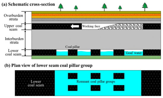
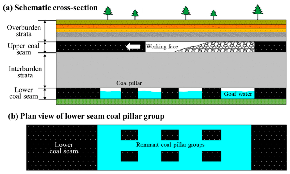
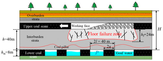
Coal remains a cornerstone of China’s energy supply and continues to play a critical role in supporting economic development and social stability [1,2,3]. However, with the continued depletion of shallow coal resources and the ongoing ecological restoration of mining areas, many coal mines are entering a stage of deep-resource recovery under increasingly complex geological conditions or are approaching closure. During the early development of multi-seam coalfields, limited mining technology and management often led to the preferential extraction of readily accessible lower seams using room-and-pillar or roadway-and-pillar methods, frequently without systematic planning for subsequent resource recovery [4,5]. Consequently, extensive abandoned goafs and groups of remnant coal pillars were left in the lower seams, as illustrated in Figure 1. With advances in mining technology and the increasing demand for improved resource recovery, upward re-mining has become a practical option for recovering upper-seam resources above previously mined lower seams [6]. This mining configuration, however, raises important concerns regarding the stability and safety of upper-seam extraction above goafs supported by remnant coal pillar groups. The problem is further complicated by the hydrogeological conditions of coal-bearing strata in northern China [7,8,9]. Over time, water originating from surface recharge and surrounding aquifers may accumulate within abandoned lower-seam goafs and develop appreciable hydraulic pressure [10]. Consequently, upward extraction of the overlying seam may be conducted above a pressurized water-bearing goaf, creating a potential pathway for water inrush through the floor of the upper working face.
Figure 1.
Schematic diagram of upward re-mining in the overlying coal seam above a goaf with remnant coal-pillar groups.
Unlike conventional downward longwall mining in multi-seam deposits, remnant coal pillars and surrounding goafs form a highly heterogeneous load-bearing system with pronounced spatial variability [11]. After the goaf is formed, the remnant pillars continuously support the overburden over extended periods, while their mechanical state evolves under the combined effects of surrounding-rock deformation, long-term stress redistribution, progressive coal damage, and subsequent mining disturbances [12]. During upward re-mining of the upper seam, the abutment pressure induced by the advancing working face inevitably interacts with the pre-existing high-stress state of the underlying remnant pillars. This interaction may lead to pillar reloading, load redistribution, and progressive deformation and failure of the interburden strata, resulting in a complex mining-induced mechanical response [13]. The problem is further complicated by the long-term water-induced weakening of the remnant pillars due to accumulated goaf water, which may further reduce the stability margin of the pillar–interburden system [14]. Therefore, a comprehensive understanding of the stability of upward re-mining above goafs supported by remnant coal pillar groups is essential for the safe and sustainable recovery of residual coal resources.
In multi-seam mining, the responses of individual coal seams are not independent [15]. Their interactions are governed by several factors, including interseam spacing, the lithology and thickness of the interburden, mining sequence, panel dimensions, and the geometry and mechanical properties of remnant coal pillars. Previous studies have shown that goaf formation in a lower seam can induce stress relief and subsidence in the overlying strata, whereas remnant pillars may generate localized stress concentrations that are transferred through the interburden to adjacent seams [16]. As longwall extraction advances in the upper seam, the front abutment pressure further modifies the pre-existing stress field, leading to a more complex redistribution of loads between the underlying remnant pillars and goafs. This interaction becomes particularly important for closely spaced seams, where the limited thickness of the interburden makes its load-bearing capacity and deformation behavior critical to whether mining-induced disturbances from the upper and lower seams become connected [17,18,19]. Therefore, clarifying the coupled response of remnant coal pillar groups and the interburden during upper-seam face advance is essential for assessing the safety of upward re-mining in closely spaced coal seams.
In recent years, considerable research has been devoted to multi-seam mining and the stability of remnant coal pillars. These studies have employed theoretical analysis [4], numerical modeling [20,21], physical experiments [22], and field monitoring to investigate the interactions between multiple seams from the perspectives of overburden movement [23,24], stress transfer, pillar stability, and mining-induced fracture evolution. Theoretical approaches can describe stress transfer within pillar–goaf systems and establish relationships among pillar geometry, overburden loading, and interburden stability. Numerical models can further account for realistic stratigraphic conditions and face advance to resolve the spatiotemporal evolution of stress, displacement, and plastic failure, while field monitoring provides engineering-scale validation of mining-induced influence zones and abnormal ground-pressure behavior. Previous studies have shown that remnant pillars can act as major sources of stress concentration in multi-seam mining, with their influence potentially transmitted through the interburden to adjacent working faces [25,26]. However, most existing studies have focused either on the overall stability of remnant pillars or on static stress distributions under multi-seam mining conditions. The combined effects of multiple factors on the safety and stability of upward re-mining remain insufficiently understood, which limits the reliability of stability assessments and the rational design of mining layouts. Recent studies have further extended pillar-stability assessment toward advanced design and data-driven approaches [27,28]. In addition to conventional analytical, numerical, and experimental methods, AI-assisted and data-driven frameworks have increasingly been employed to characterize nonlinear relationships among pillar geometry, geological conditions, stress state, and failure behavior [29,30]. These developments highlight the need for multi-parameter stability assessment rather than single-factor design. Moreover, the hydrostatic pressure exerted by water accumulated in abandoned goafs has rarely been incorporated explicitly into stability analyses, despite documented floor water-inrush events, such as that at Dongyu Coal Mine [31]. Consequently, a clear research gap remains in evaluating the safety and stability of upward re-mining under the combined effects of remnant pillar-group support and pressurized water-bearing goafs.
Overall, the stability of upward re-mining above goafs supported by remnant coal pillar groups cannot be attributed solely to pillar bearing capacity or interburden stability. Instead, it is governed by a complex mechanical process involving long-term pillar loading and degradation, mining-induced damage of the interburden, water-induced weakening and hydraulic pressure within the goaf, and renewed disturbance caused by upper-seam extraction. These factors may interact adversely, but they may also exhibit competitive or synergistic effects, with their combined influence depending on the load-bearing state of the pillar group, the integrity of the interburden, and the spatial evolution of stress and failure zones during repeated mining. Accordingly, a physically meaningful stability assessment for upward re-mining requires a clear understanding of the fundamental failure modes and spatiotemporal evolution of the remnant pillar group and interburden after formation of the lower-seam goaf, together with identification of the key structural and mechanical parameters governing system stability. To address these issues, this study first examines the progressive instability of remnant coal pillar groups and the multistage damage evolution of the interburden under repeated mining. A theoretical model is then developed to account for the combined effects of overburden loading, horizontal in situ stress, pillar-group support, and goaf water pressure, and is subsequently used to clarify how these factors control the stability and safety boundaries of upward re-mining.
2. Failure Characteristics of Mining-Disturbed Interburden Strata and Coal Pillars
2.1. Failure Characteristics of Remnant Coal Pillars in the Goaf
Following room-and-pillar or roadway-and-pillar extraction of the lower seam, irregular abandoned goafs and groups of remnant coal pillars are typically formed. The stability of the overlying roof strata is then maintained primarily by the supporting action of the remnant pillar group, which is a key prerequisite for subsequent upward re-mining of the upper seam. Previous studies indicate that failure of a remnant pillar group does not occur simultaneously throughout the entire system [16]; instead, it develops progressively and exhibits the following characteristics:
- (1)
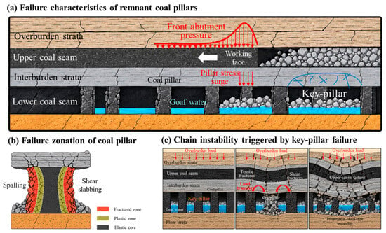
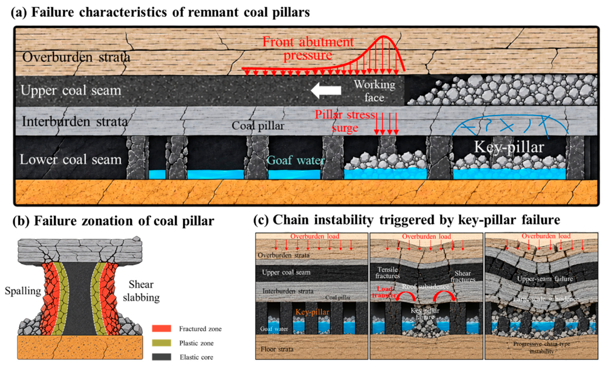
- An individual coal pillar exhibits a progressive failure pattern that develops from the outer margins toward the interior, as illustrated in Figure 2b. Across the pillar cross-section, spalling and shear slabbing initially occur along the exposed sides adjacent to roadways and goafs. The plastic failure zones then progressively propagate inward from both margins, leaving an elastic load-bearing core of finite width in the central part of the pillar. The relative width of this elastic core is a key indicator of pillar load-bearing capacity, with a wider elastic core generally corresponding to a higher residual bearing capacity. For narrow pillars, the plastic zones developing from opposite sides may coalesce, resulting in a substantial loss of effective load-bearing capacity. At the pillar corners, failure is typically characterized by combined tensile–shear damage, accompanied by extensive development of shear fractures along the pillar sides. In contrast, the central portion of the pillar is subjected to relatively high vertical compressive stress and therefore tends to exhibit vertical compressive cracking or splitting failure.Figure 2. Schematic illustration of failure characteristics of goaf pillar groups and individual coal pillars.
- (2)
- At the pillar-group scale, failure tends to initiate at boundary pillars, whereas instability of key pillars within the goaf may trigger cascading failure of the entire pillar system, as illustrated in Figure 2c. Field observations and previous studies indicate that pillars located near goaf boundaries, roadway intersections, and irregular excavation geometries—such as triangular and island pillars—are particularly prone to high stress concentrations and therefore tend to exhibit spalling and localized failure at an early stage. This behavior is mainly attributed to the additional lateral loads transferred from the surrounding roof strata to the boundary pillars. For pillar groups within the goaf, according to the key-pillar theory proposed by Feng et al. [32,33], a key pillar may fail prematurely and lose its load-bearing capacity because of insufficient dimensions, water-induced weakening, or long-term creep damage. The roof load previously carried by that pillar is then redistributed to the surrounding pillars. If the resulting stress increase exceeds the bearing capacity of adjacent pillars, the initial failure of a key pillar may propagate through the pillar group as a cascading instability. Such progressive failure can lead to large-scale damage of the roof strata and the overlying coal seam and, in severe cases, may extend upward to the ground surface.
- (3)
- Under repeated mining, coal pillars subjected to stress disturbance tend to undergo damage and failure earlier than less disturbed pillars, resulting in an overall intensification of pillar degradation, as illustrated in Figure 2a. As the upper-seam working face advances, a pronounced vertical front abutment pressure develops ahead of the coal face and may reach several times the initial in situ stress. This abutment pressure is transmitted downward into the floor strata. Consequently, remnant pillars located within the affected zone experience a rapid increase in stress and are therefore more susceptible to early damage and failure, which may subsequently propagate toward surrounding, less disturbed regions. The sequence of pillar failure is therefore strongly dependent on the spatial distribution of mining-induced disturbance. If the disturbed pillar is a key load-bearing pillar, its failure can more readily initiate cascading instability within the pillar group. Moreover, pillars affected by repeated mining generally exhibit more severe damage, characterized by enlarged plastic failure zones and a reduced or completely lost elastic core.
2.2. Failure Characteristics of Interburden Strata
The integrity and degree of damage of the interburden strata are directly related to the feasibility and safety of upward re-mining. According to the mining sequence in upward extraction of multiple coal seams, the damage evolution of the interburden can generally be divided into three stages: (1) initial damage induced by roadway-and-pillar extraction of the lower seam; (2) progressive deterioration caused by long-term water-induced weakening and creep damage; and (3) renewed failure of the floor strata during re-mining of the upper seam.
- (1)
- Initial damage stage induced by roadway-and-pillar mining of the lower seam.
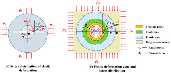
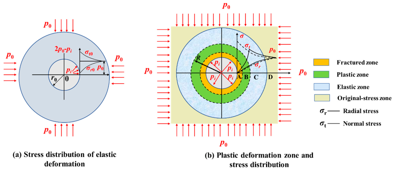
Before roadway-and-pillar extraction, the surrounding rock mass is generally assumed to remain in an elastic state, with the initial vertical stress (p0) equal to the weight of the overlying strata. After excavation, the initial stress field is redistributed, resulting in localized stress concentrations in the surrounding rock. For theoretical analysis, the roadway can be idealized as a circular opening subjected to a biaxial isotropic in situ stress field, and the corresponding stress distribution is illustrated in Figure 3a. When the redistributed stress exceeds the rock-mass strength, plastic deformation develops around the roadway and progressively extends into the surrounding rock, forming a plastic zone and inducing damage in the coal pillars as well as the roof and floor strata [16]. Based on limit equilibrium theory, the surrounding rock can be divided into several characteristic zones, as shown in Figure 3b. Within the inner part of the plastic zone (Zone A), the rock strength is markedly reduced and becomes insufficient to sustain the initial stress, leading to fracturing; this region is therefore defined as the fractured zone. In the outer part of the plastic zone (Zone B), the stress exceeds the initial in situ stress. Together with the stress-increased portion of the adjacent elastic region, this zone constitutes the principal load-bearing region and is also referred to as the stress-concentration zone. Farther away from the roadway, the rock mass gradually returns to the undisturbed in situ stress state and forms the original-stress zone. If the lithological difference between the coal pillar and roof strata is neglected and the surrounding rock is assumed to be homogeneous and isotropic under equal biaxial compression, the widths of the plastic zones induced in the roof and coal pillar by a single roadway excavation can be approximately determined from the following expression:
where R denotes the plastic-zone width in the roof and coal pillar; p0 is the initial in situ stress; C and φ are the cohesion and internal friction angle of the surrounding rock, respectively; pi is the roadway support pressure; and r0 is the radius of the circular roadway.
Figure 3.
Stress distribution and zoning characteristics of the surrounding rock in the roadway.
- (2)
- Stage of aggravated damage and failure induced by long-term water immersion weakening and time-dependent creep.
After room-and-pillar mining of the lower coal seam, a structural configuration is formed in which the overlying roof strata are supported by a group of remnant coal pillars. According to rock mechanics theory, coal and rock masses generally exhibit pronounced creep behavior and long-term strength characteristics [34,35]. In other words, even under a constant roof load, the deformation of the coal-pillar group continues to develop with time, resulting in time-dependent creep damage and progressive failure. When the stress acting on a coal pillar exceeds the maximum stress that it can sustain over the long term without creep-induced failure, damage and eventual failure will occur. As the failed coal pillars gradually lose their load-bearing capacity, damage to the interburden strata is further intensified, potentially leading to local collapse. During this process, water continuously accumulates within the goaf, resulting in prolonged water immersion of the coal pillars and interburden strata. Such long-term water-rock interaction further weakens and softens the mechanical properties of both the coal pillars and the interburden strata, thereby accelerating their time-dependent damage and failure [36], as illustrated in Figure 2a.
- (3)
- Failure stage of the floor strata induced by repeated mining of the upper coal seam.
When the upper coal seam is mined upward using the longwall mining method, advancement of the working face disturbs the original stress equilibrium of the rock mass surrounding the goaf. As a result, the roof strata can generally be divided into a stress-relief zone, a stress-concentration zone, and an undisturbed in situ stress zone. Meanwhile, the floor strata, i.e., the interburden strata between the upper and lower coal seams, undergo downward deformation and progressive failure from the upper part to the deeper section under the redistribution of vertical and horizontal stresses. Eventually, three plastic failure zones with distinctly different mechanical characteristics are formed: the active limit zone, transition zone, and passive limit zone [37]. According to the “three-zone” theory of floor failure [38], mining of the upper coal seam ultimately induces an inverted saddle-shaped floor failure zone extending to a certain depth, as illustrated in Figure 4. Under shallow mining conditions, the maximum depth of the floor failure zone can generally be estimated using the following empirical equations, and the maximum calculated value is conservatively adopted.
where hf is the maximum floor failure depth induced by extraction of the upper coal seam, and L is the inclined length of the mining face.
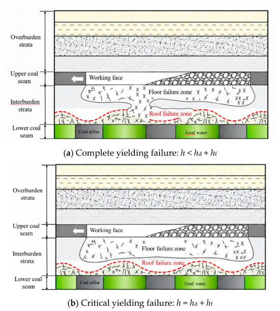
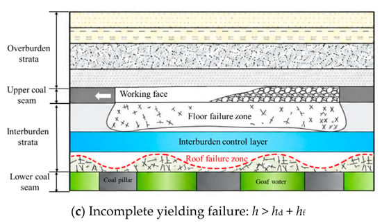
Figure 4.
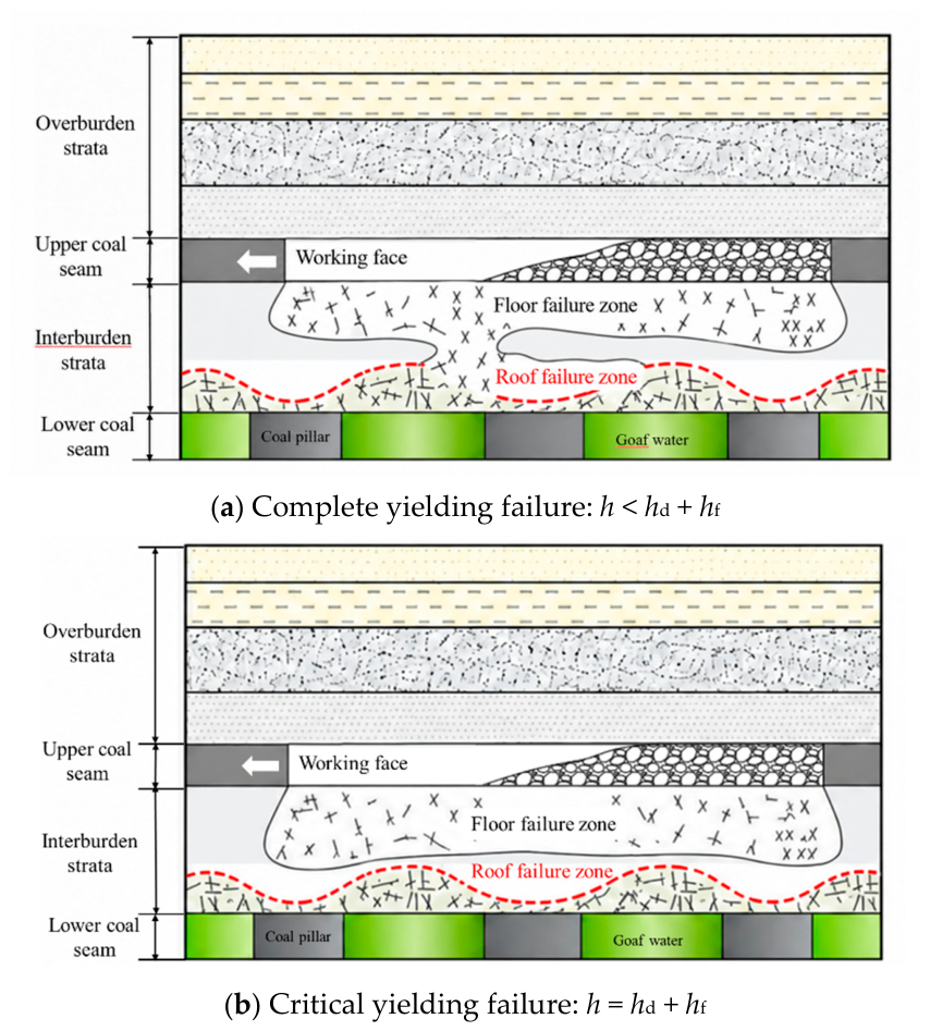
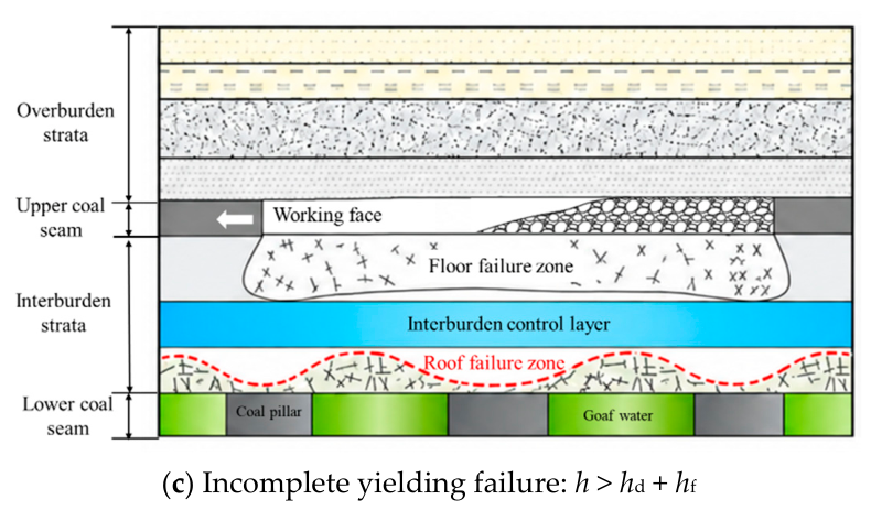
Schematic diagram of the three yielding-failure states of the interburden strata.
Therefore, to comprehensively evaluate whether the upper coal seam overlying a goaf supported by residual coal-pillar groups can be safely mined upward, it is essential to determine the integrity of the interburden strata. Specifically, it is necessary to assess whether the interburden strata will undergo complete yielding and failure throughout their entire thickness, or even collapse, during upward mining. Based on the above analysis, the yielding and failure states of the interburden strata can be classified into three categories [4]: complete yielding failure, critical yielding failure, and incomplete yielding failure, as illustrated in Figure 4.
To quantitatively distinguish the three yielding-failure states, the residual thickness of the relatively intact interburden control layer, hk, is defined as:
where h is the total thickness of the interburden strata, hd is the maximum roof failure height above the lower coal seam, and hf is the maximum floor failure depth induced by extraction of the upper coal seam.
hk = h - hd - hf
The condition h = hd + hf defines the critical yielding state separating complete yielding failure from incomplete yielding failure. When h < hd + hf, i.e., hk < 0, the roof failure zone above the lower seam overlaps with the floor failure zone beneath the upper seam, corresponding to complete yielding failure of the interburden strata. When h = hd + hf, i.e., hk = 0, the two failure zones become tangent, defining the critical yielding-failure condition. When h > hd + hf, i.e., hk > 0, the two failure zones remain separated by an intact interburden control layer of thickness hk, corresponding to incomplete yielding failure.
- (1)
- Complete yielding failure of the interburden strata.
When the vertical separation between the two coal seams is relatively small, the interburden strata are highly susceptible to complete yielding failure, as illustrated in Figure 4a. During repeated mining, the floor failure zone induced by extraction of the upper coal seam may progressively connect with the roof failure zone developed above the lower coal seam. As a result, the interburden strata experience substantial damage throughout their full thickness, accompanied by a pronounced deterioration in structural integrity and continuity and the intensive development of interconnected vertical and horizontal fractures. Under such conditions, the load-bearing capacity of the interburden strata available to support safe upward extraction of the upper coal seam is markedly weakened, leading to poor overall mining stability. If high-head water is present in the underlying goaf, the mining-induced fracture network may provide a preferential hydraulic pathway connecting the water-filled goaf with the upper mining area, thereby significantly increasing the risk of water inrush from the underlying goaf.
- (2)
- Critical yielding failure of the interburden strata.
When the vertical separation between the two coal seams is moderate, the interburden strata tend to remain in a critical yielding state, as illustrated in Figure 4b. Under this condition, the thickness of the interburden strata is approximately equal to the combined vertical extent of the roof failure zone above the lower coal seam and the floor failure zone beneath the upper coal seam, such that the two failure zones are essentially tangent to each other. Localized connection may nevertheless occur near the uppermost extent of the roof failure zone, where it is most likely to intersect the floor failure zone induced by repeated mining of the upper seam. In contrast to the complete yielding case, a certain thickness of relatively intact strata remains within the regions protected by the remnant coal pillars, thereby preserving part of the load-bearing capacity of the interburden and resulting in comparatively higher mining stability. However, localized mining-induced fractures may still coalesce to form preferential water-conducting pathways between the goafs of the upper and lower coal seams. If such hydraulic pathways become connected with water accumulated in the underlying goaf, water inrush from the floor goaf may consequently occur.
- (3)
- Incomplete yielding failure of the interburden strata.
When the vertical separation between the two coal seams is sufficiently large, the interburden strata do not undergo complete yielding failure, as illustrated in Figure 4c. Under this condition, the roof failure zone above the lower coal seam remains separated from the floor failure zone induced by mining of the upper coal seam, leaving a certain thickness of relatively intact rock mass between the two damaged zones. This intact rock mass is herein defined as the interburden control layer [4]. The thickness of the interburden control layer not only directly governs the safety and feasibility of upward mining, but also plays a critical role in impeding hydraulic connection with the underlying goaf. A thicker interburden control layer provides greater residual load-bearing capacity and hydraulic isolation, thereby enhancing the stability of upward mining and reducing the likelihood of water inrush from the underlying goaf.
For the incomplete yielding state, hk may be regarded as a residual structural and hydraulic safety margin of the interburden; a larger hk generally indicates greater separation between the two mining-induced failure zones.
Equation (2) provides the maximum depth of floor failure induced by mining of the upper coal seam. Although the failure height of the roof strata caused by excavation of a single roadway can be approximately estimated using Equation (1), this formulation is not suitable for determining the maximum roof failure height under the support of a coal-pillar group, nor does it account for the hydraulic head associated with water accumulated in the goaf. Therefore, a theoretical mechanical model is developed below to further derive the maximum roof failure height under coal-pillar group support.
3. Maximum Roof Failure Height Under Coal-Pillar Group Support
3.1. Establishment of the Mechanical Model
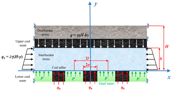
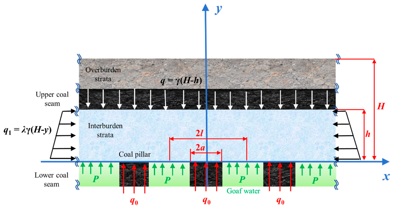
After room-and-pillar mining of the lower coal seam, the overlying strata generally remain relatively intact without extensive collapse owing to the support provided by the residual coal-pillar group. Accordingly, considering both the supporting effect of the coal-pillar group and the hydraulic head exerted by water accumulated in the goaf, the goaf is assumed to extend infinitely in the horizontal direction and the coal pillars are approximately symmetrically distributed. The entire overlying rock mass is therefore selected as the analytical domain and idealized as a semi-infinite planar body of unit thickness. The overburden load and horizontal in situ stress are simultaneously taken into account, and the problem is formulated as a two-dimensional elastic half-plane problem. By introducing an appropriate coordinate system to facilitate the analytical derivation, the resulting mechanical model is established as shown in Figure 5.
Figure 5.
Mechanical model of combined overburden support by goaf pillar groups and water pressure.
In Figure 5, the mining depth of the lower coal seam is denoted by H. The rock strata between the upper and lower coal seams are defined as the interburden strata, with a thickness of h, while the width of an individual coal pillar is 2a. A single goaf span together with its adjacent coal pillar is regarded as an individual load-bearing unit, with a total width of 2l; accordingly, the span of the individual goaf is 2(l-a). The overburden load at a depth y can be expressed as γ(H-y), where γ is the average unit weight of the overlying strata. Therefore, the vertical load acting on the top surface of the interburden strata is given by q = γ(H-h). The horizontal in situ stress can be expressed as q1 = λγ(H-y), where λ is the lateral pressure coefficient. The water pressure within the goaf of the lower coal seam, denoted by P, can be obtained from field measurements. The support stress provided by an individual coal pillar is denoted by q0. Because the goaf area and its lateral extent are assumed to be infinite, each load-bearing unit can be treated as an independent representative element. The water pressure P acting within the goaf and the pillar support stress q0 provided by the coal pillar are therefore assumed to jointly sustain the overburden load corresponding to the roof area carried by that load-bearing unit. According to static equilibrium, the following relationship can be obtained:
2aq0 + P(2l - 2a) = 2lγH
Here, “joint support” refers only to vertical static equilibrium. Within a representative unit of width 2l, the coal pillar of width 2a provides an upward contact stress q0, whereas the water-filled goaf of width 2(l-a) exerts an upward hydrostatic pressure P on the roof. These two spatially separated normal boundary tractions jointly balance the downward overburden load. Because the analytical medium is treated as linear elastic and the loading components are independent boundary tractions, their induced stress fields can be superposed.
According to Equation (4), the pillar support stress provided by an individual coal pillar to the overlying roof strata can be expressed as:
3.2. Mechanical Model Solution
When solving the mechanical model shown in Figure 5 using elasticity theory, the following assumptions are introduced:
- (1)
- The coal and rock masses are treated as homogeneous, isotropic, and linearly elastic media.
- (2)
- The overall lateral extent of the pillar–goaf system is assumed to be sufficiently large relative to the characteristic width of an individual load-bearing unit, such that outer-boundary effects can be neglected.
- (3)
- All coal pillars are assumed to have an identical width, and all goaf spans are assumed to be equal.
- (4)
- The overburden load, the water pressure within each goaf, and the supporting force provided by each coal pillar are all idealized as uniformly distributed loads with identical intensities within their respective categories.
- (5)
- The thickness of the interburden strata, h, is assumed to be no less than half the width of a single load-bearing unit, i.e., h ≥ l.
Under these assumptions, the mechanical model can be solved using the principle of superposition. The stress field within the semi-infinite plane may be decomposed into the superposed contributions of three loading components: (1) the overburden load and horizontal in situ stress; (2) the supporting forces exerted by the coal-pillar group; and (3) the water pressure acting within the goaf.
The stress components induced by the overburden load and the horizontal in situ stress can be expressed as follows:
where is the normal stress in the x-direction induced by the overburden load and horizontal in situ stress; is the normal stress in the y-direction induced by the overburden load and horizontal in situ stress; and is the shear stress induced by the overburden load and horizontal in situ stress.
Considering only the supporting forces exerted by the coal-pillar group, the spatial distribution of the pillar support load in Figure 5 can be expressed in the following piecewise form:
where m is an integer, i.e., m = …, −2, −1, 0, 1, 2, ….
The semi-infinite plane is subjected to a discontinuous loading pattern imposed by the coal-pillar group. The resulting stress components can be derived using the stress-function approach. According to the loading form given in Equation (7), a hyperbolic stress function, Φ, may be introduced as follows [16]:
where b = nπ/l; n is a positive integer, i.e., (n = 1, 2, 3…, n); and C1, C2, C3, and C4 are integration constants determined from the boundary conditions.
Based on the stress function given in Equation (8), the corresponding stress components can be obtained from the following relations:
where denotes the normal stress in the x-direction induced by the supporting forces of the coal-pillar group; denotes the normal stress in the y-direction induced by the supporting forces of the coal-pillar group; and denotes the corresponding shear stress.
Neglecting the shear stress distribution along the contact interface between the coal-pillar group and the overlying roof strata, the stress boundary conditions of the mechanical model can be expressed by Equations (10) and (11), where m is an integer.
Substituting the stress function given in Equation (8) into Equation (9) and applying the boundary conditions specified in Equations (10) and (11), the stress components induced solely by the supporting forces of the coal-pillar group can be derived as follows:
where bn is given by:
For the stress components induced by the goaf water pressure P, the water-filled goaf and the coal-pillar group are symmetrically distributed along the x-direction. Therefore, the corresponding stress components can be derived directly from those obtained for the coal-pillar group by invoking the symmetry principle. Specifically, the following substitutions are made in Equations (12) and (13): a is replaced by l-a, x is replaced by x-l, and q0 is replaced by P. Accordingly, the stress components induced solely by the goaf water pressure can be expressed as follows:
where denotes the normal stress in the x-direction induced by the goaf water pressure; denotes the normal stress in the y-direction induced by the goaf water pressure; and denotes the corresponding shear stress. The coefficient cn is given by:
According to the principle of superposition, the stress components induced by the overburden load, horizontal in situ stress, supporting forces of the coal-pillar group, and goaf water pressure can be superimposed to obtain the resultant stress components within the semi-infinite plane, representing the entire overlying rock mass, as follows:
where σx and σy denote the normal stress components in the x- and y-directions, respectively, within the overlying strata, and τxy denotes the corresponding shear stress component.
It should be noted that the regular and periodic arrangement of coal pillars adopted in the present model represents an idealized configuration introduced to obtain an analytical solution. In actual abandoned room-and-pillar workings, remnant pillars may exhibit considerable variability in width, spacing, and shape. For pillar groups with moderate geometric irregularity, the actual pillar and tributary areas may be converted into equivalent pillar widths and goaf spans while approximately preserving the load-bearing area ratio and average load carried by each representative unit. This treatment allows the present analytical model to provide a first-order estimate of the overall stress-transfer behavior.
For highly irregular pillar groups, the periodic loading function in Equation (7) may, in principle, be replaced by a piecewise nonuniform loading function defined according to the actual positions and widths of individual pillars. However, under such irregular boundary-loading conditions, an analytical stress function satisfying the corresponding boundary conditions is generally difficult to construct, and a closed-form solution may no longer be obtainable. In such cases, numerical methods, such as finite-element or finite-difference modeling, are more appropriate for resolving the stress redistribution associated with complex pillar geometry and nonuniform loading. Therefore, the present model is mainly applicable to pillar groups with approximately regular spatial distributions and should be regarded as a theoretical framework for identifying the dominant mechanical mechanisms and first-order safety boundaries.
3.3. Maximum Roof Failure Height
Equation (16) describes the stress-field distribution within the overlying strata after room-and-pillar mining of the lower coal seam. It can be seen that the roof stress field is governed by multiple factors, including the mining depth, horizontal in situ stress, coal-pillar width, span of an individual goaf, and goaf water pressure. Based on the stress components obtained from Equation (16), the major and minor principal stresses at any point within the overlying strata can be determined as follows:
where σ1 denotes the major principal stress, and σ3 denotes the minor principal stress.
According to the Mohr–Coulomb failure criterion for shear yielding of rock masses [39,40], the yielding state at any point within the entire overlying rock mass can be evaluated using the following expression:
where Rc denotes the uniaxial compressive strength of the intact rock mass, K is a coefficient, and φ is the internal friction angle of the rock mass.
Substituting Equation (16) into Equations (17) and (18) and rearranging yields the function y(x). For the semi-infinite plane, the extrema of the yielding boundary can be determined by differentiating y(x) with respect to x and imposing the condition . In this way, the extremum points of the yielded zone within the entire roof rock mass, including both local maxima and minima, can be identified. The corresponding y-coordinates are then obtained by substituting the x-coordinates of these extremum points back into y(x). The maximum y-value represents the maximum roof failure height, hd, whereas all points satisfying the function y(x) collectively define the boundary of the roof yielding zone.
It should be noted that the present failure-height calculation is primarily based on the Mohr–Coulomb shear-yield criterion. Local tensile cracking may also occur near the roof of goaf openings where confinement is low. However, a separate tensile-strength criterion is not explicitly incorporated into the present analytical boundary. Therefore, the calculated hd should be interpreted as a shear-yield-controlled failure height. For rock strata with low tensile strength or pronounced bedding discontinuities, tensile cracking may locally extend beyond the predicted boundary. A combined shear–tensile failure criterion will be considered in future extensions of the model.
4. Effects of Different Factors on the Safety of Upward Mining
The preceding sections present, respectively, a method for determining the maximum roof failure height above the lower coal seam after room-and-pillar mining under coal-pillar group support, and an empirical expression for estimating the floor failure depth induced by longwall caving extraction of the upper coal seam [Equation (2)]. To further investigate the safety of upward re-mining under coal-pillar group support, five key influencing factors are considered, namely mining depth, horizontal in situ stress, coal-pillar width, span of an individual goaf, and goaf water pressure. The effects of these factors on the stability and safety of upward mining are systematically analyzed, with the aim of elucidating the governing influence patterns and providing a theoretical basis for safe mining design and the formulation of targeted hazard-control measures.
Based on the engineering background of upward mining at a coal mine in China, comparative cases with different parameter settings are established to calculate the yielding and failure states of the interburden strata under the influence of different factors, thereby further evaluating the safety of upward mining, as shown in Figure 6. The length of the upper-seam longwall face is set to L = 200 m. According to Equation (2), the maximum floor failure depth induced by longwall caving extraction of the upper coal seam is calculated to be approximately hf = 24 m.
Figure 6.
Schematic diagram of the engineering conditions for upward mining at a coal mine.
The yielding and failure state of the interburden strata is a key criterion for evaluating the safety of upward mining, as illustrated in Figure 4. Assuming that the floor failure depth induced by longwall caving extraction of the upper coal seam remains constant, the yielding condition of the interburden strata is primarily governed by the roof failure height caused by room-and-pillar mining of the lower coal seam. Accordingly, the effects of different influencing factors on roof failure above the lower coal seam are analyzed below to assess the safety and feasibility of upward mining. For a given interburden thickness, a smaller roof failure height above the lower coal seam corresponds to a higher level of stability and safety for upward mining.
4.1. Effect of Horizontal In Situ Stress
According to Equation (16), the in situ stress field also affects the stability of the roof strata above the lower coal seam, particularly through the horizontal in situ stress component. For analytical convenience, a special case is considered in which the coal-pillar width satisfies 2a = l (i.e., a = l/2) and the goaf water pressure is set to P = 0. Under these conditions, the tensile stress σx, which is prone to develop near the center of the roof above an individual goaf, can be evaluated by substituting x = ±l and y = 0 into Equation (16), yielding:
In the above expression, is an infinite convergent series. For n = 1, 2, 3, …, the series converges to −π/4. Therefore, the expression can be simplified as follows:
σx = (λ - 1)γH
Equation (20) indicates that σx is closely related to the horizontal in situ stress. When λ > 1, σx is compressive, and tensile stress is unlikely to develop in the roof strata, which is favorable for maintaining roof stability. In contrast, when λ < 1, tensile stress may develop in the roof, thereby promoting progressive damage and failure. Therefore, for upward re-mining of the upper coal seam, characterization of the horizontal in situ stress is of particular importance. A lateral pressure coefficient greater than unity, especially at relatively high values, is conducive to enhancing the stability and feasibility of upward mining. According to statistical data from in situ stress measurements in Chinese coal mines, horizontal stress under shallow mining conditions is commonly greater than the vertical stress, corresponding to a lateral pressure coefficient generally greater than 1. From the perspective of the lateral pressure coefficient, therefore, shallow upward mining of multiple coal seams tends to exhibit more favorable stability conditions.
4.2. Effect of Mining Depth
Mining depth is one of the key factors governing the safety of upward re-mining, as it directly controls the magnitude of the load transferred to the coal pillars. To further elucidate the influence of mining depth on the stability of upward re-mining, a controlled-variable analysis is conducted. The average unit weight of the strata is set to γ = 23 kN/m3, the interburden thickness to h = 40 m, the average uniaxial compressive strength of the rock mass to Rc = 25 MPa, and the average internal friction angle of the rock mass to φ = 32°. The remaining parameters are held constant as follows: the lateral pressure coefficient λ = 1, the coal-pillar width 2a = 10 m, the width of a single load-bearing unit consisting of one goaf span and its adjacent coal pillar 2l = 40 m, and the goaf water pressure P = 0 MPa. According to the Mohr–Coulomb failure criterion [Equation (18)], the maximum yield-function value Fmax developed in the roof strata under coal-pillar group support is defined as follows:
By varying the mining depth of the lower coal seam from H = 100 to 500 m, the maximum yield-function value within the roof strata supported by the coal-pillar group and its corresponding location are calculated for each mining depth. Meanwhile, the average load acting on the coal pillars is determined using Equation (5). The safety of upward re-mining is then evaluated by comparing the maximum yield-function value with the average uniaxial compressive strength of the rock mass Rc, and by assessing whether the pillar load-bearing stress exceeds the ultimate bearing capacity of the pillars. The calculated results are summarized in Table 1.
Table 1.
Maximum yield-function value in the roof strata supported by the coal-pillar group and its location at different mining depth.
According to the Wilson formula [41], the ultimate bearing stress of a coal pillar, σs, is primarily governed by the uniaxial compressive strength of the coal, Rm, the thickness of the lower coal seam, hm, and the coal-pillar width, and can be expressed as:
It should be noted that the Wilson formula provides a reference estimate of pillar bearing strength and does not explicitly account for the long-term degradation induced by water immersion and time-dependent creep. As discussed in Section 2.2, prolonged water–rock interaction and creep damage may progressively reduce the effective strength of remnant coal pillars. To incorporate this effect in a generalized form, a long-term water–creep strength reduction coefficient, ηw, is introduced:
where σsw is the effective long-term bearing stress of the water-weakened coal pillar and 0 < ηw ≤ 1. Combining this relationship with Equation (5), the critical mining depth under long-term water-immersion and creep conditions can be expressed as:
σsw = ηwσs
For the case of P = 0, this expression reduces to:
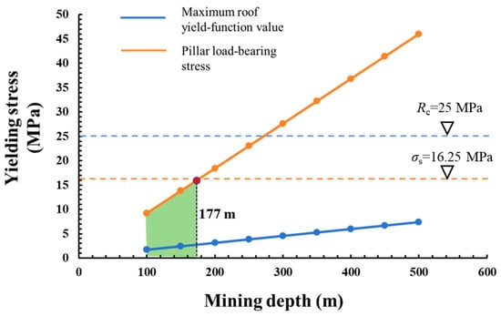
Using Equation (22), with hm = 8 m and Rm = 15 MPa, the ultimate bearing stress of the coal pillar is calculated as σs = 16.25 MPa. Based on these results, the relationships between the maximum yield-function value and the pillar load-bearing stress at different mining depths of the lower coal seam are plotted, as shown in Figure 7.
Figure 7.
Relationship between maximum roof yield-function value and pillar load-bearing stress at different mining depths of the lower coal seam.
As shown in Figure 7, the maximum yield-function value in the roof strata increases approximately linearly with increasing mining depth. For every 100 m increase in mining depth, the maximum yield-function value increases by approximately 0.7 MPa. However, as the mining depth of the lower coal seam increases from 100 to 500 m, the maximum yield-function value in the roof remains below 25 MPa, indicating that yielding failure does not occur in the roof strata. This suggests that, under room-and-pillar mining conditions, the support provided by the coal-pillar group can generally maintain the stability of the overlying roof strata, which is broadly consistent with field observations [16]. According to Table 1, the vertical location at which the maximum yield-function value occurs is essentially independent of mining depth and remains approximately 6–7 m above the lower coal seam. In addition, as shown in Figure 7, the pillar load-bearing stress increases approximately linearly with mining depth. When the mining depth reaches approximately 177 m, the pillar load-bearing stress reaches the reference ultimate bearing stress of 16.25 MPa calculated using the Wilson formula. Therefore, 177 m represents the theoretical critical depth without considering long-term strength degradation. Under prolonged water immersion and creep, the effective pillar strength decreases to σsw = ηwσs, and the corresponding critical mining depth will be lower. Therefore, to ensure the feasibility and safety of upward re-mining, both the ultimate bearing capacity of the coal pillars and the yielding behavior of the roof strata should be considered simultaneously. Under the geometric and mechanical conditions considered in this study, the theoretical critical mining depth is approximately 177 m, corresponding to the shaded region shown in Figure 7.
According to Equation (25), this relationship indicates that the critical mining depth decreases approximately in proportion to the reduction in the long-term pillar strength. Therefore, the critical depth of approximately 177 m obtained using the unweakened Wilson strength should be interpreted as an upper-bound theoretical value for the investigated geometric conditions. In water-affected abandoned goafs, the actual critical depth may be lower, depending on the degree of water-induced degradation and creep damage. Because reliable long-term strength-reduction data for the investigated pillars are currently unavailable, no specific value of ηw is assumed in the present study. Site-specific laboratory testing or long-term monitoring is required to determine this coefficient for engineering application.
4.3. Effect of Goaf Water Pressure
After room-and-pillar mining of the lower coal seam, water may progressively accumulate within the goaf over time. When the volume of accumulated water is limited, the resulting hydraulic pressure acting on the roof strata is generally negligible. However, if the goaf water becomes hydraulically connected to a remote water source, a sustained water pressure may develop, placing subsequent extraction of the upper coal seam under pressurized-water conditions. The floor-goaf water inrush event at the Dongyu Coal Mine represents a typical example of such a mechanism [31]. On the one hand, prolonged water accumulation can induce time-dependent weakening of the coal pillars and surrounding rock mass. On the other hand, the resulting water pressure can indirectly alter the load carried by the coal pillars. To further investigate the influence of goaf water pressure on the safety of upward re-mining, a controlled-variable analysis is conducted by maintaining the mining depth at H = 200 m and varying the goaf water pressure over the range P = 0–1.4 MPa. The calculated results are summarized in Table 2.
Table 2.
Maximum yield-function value in the roof strata supported by the coal-pillar group and its location at different goaf water pressure.
In China, the water-inrush coefficient method is widely used for assessing the risk of floor water inrush and can be expressed as follows [42]:
T = P/(h - h1)
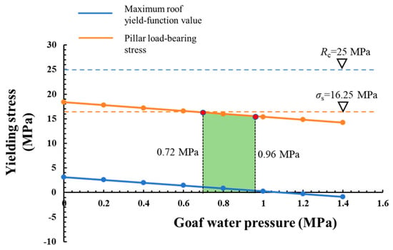
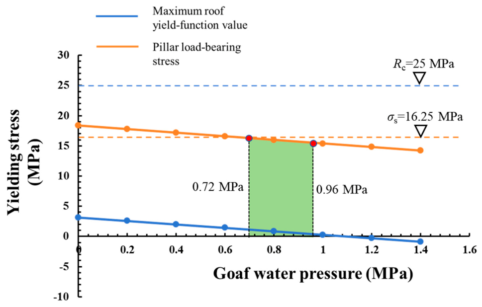
According to Equation (26), with an interburden thickness of h = 40 m and a maximum floor failure depth of approximately hf = 24 m induced by longwall caving extraction of the upper coal seam, the critical water-inrush coefficient is taken as T = 0.06 MPa/m in accordance with the relevant Chinese standard. Accordingly, the critical goaf water pressure for floor water inrush during upward mining is calculated to be Pm = 0.96 MPa. Based on this threshold, the relationships between the maximum yield-function value and the pillar load-bearing stress under different goaf water pressures are plotted, as shown in Figure 8.
Figure 8.
Relationship between maximum roof yield-function value and pillar load-bearing stress under different goaf water pressures.
As shown in Figure 8, both the maximum yield-function value in the roof strata and the pillar load-bearing stress decrease approximately linearly with increasing goaf water pressure. For every 0.1 MPa increase in goaf water pressure, the maximum yield-function value decreases by approximately 0.29 MPa, while the pillar load-bearing stress decreases by approximately 0.30 MPa. This indicates that the presence of hydraulic pressure beneath the roof strata can partially offset the overburden load transferred to the coal pillars, thereby reducing the likelihood of pillar instability and roof yielding failure. When the water pressure exceeds approximately 1.2 MPa, the maximum yield-function value becomes negative, indicating that the minimum principal stress within the roof increases under hydraulic confinement and that roof failure is less likely to occur. According to Table 2, the elevation of the maximum yield-function value remains essentially unaffected by the goaf water pressure and is maintained at approximately 6 m. To ensure the safety of upward re-mining, the ultimate bearing capacity of the coal pillars, roof yielding failure, and the risk of water inrush from the underlying goaf should be considered simultaneously. For the investigated geometric, mechanical, and hydraulic conditions, the calculated theoretical safe water-pressure range is approximately 0.72–0.96 MPa, corresponding to the shaded region in Figure 8. This result suggests that, during drainage of accumulated goaf water, the hydraulic pressure should be maintained within an appropriate range; excessively high or excessively low water pressure may both be detrimental to the safety of upward mining. Furthermore, if the goaf water pressure is taken as the critical water pressure, i.e., P = Pm = 0.96 MPa, and the pillar load-bearing stress is assumed to reach the ultimate bearing stress, i.e., q0 = σs = 16.25 MPa, the critical mining depth of the lower coal seam is calculated from Equation (5) to be approximately 208 m.
It should be emphasized that the lower limit of this interval is governed by coal-pillar stability, whereas the upper limit is controlled by the floor water-inrush criterion. Therefore, the calculated range of 0.72–0.96 MPa is specific to the geometric, mechanical, and hydraulic conditions adopted in this study and should not be regarded as a universal design criterion.
4.4. Effects of Coal-Pillar Width and Individual Goaf Span
Coal-pillar width and individual goaf span are among the key factors governing the safety of upward mining. The coal-pillar width directly affects both the load carried by the pillar and its ultimate bearing stress, and also indirectly influences roof yielding and failure by altering the stress distribution within the overlying strata. For analytical convenience, the width of a single load-bearing unit, consisting of one goaf span and its adjacent coal pillar, is fixed at 2l = 40 m. To further investigate the effects of coal-pillar width and individual goaf span on the safety of upward re-mining, a controlled-variable analysis is conducted. The mining depth is maintained at H = 200 m, the goaf water pressure at P = 0 MPa, the uniaxial compressive strength of the coal at Rm = 15 MPa, and the thickness of the lower coal seam at hm = 8 m. The width of an individual coal pillar, 2a, is varied from 5 to 30 m. The calculated results are summarized in Table 3.
Table 3.
Maximum yield-function value in the roof strata supported by the coal-pillar group and its location at different coal-pillar width.
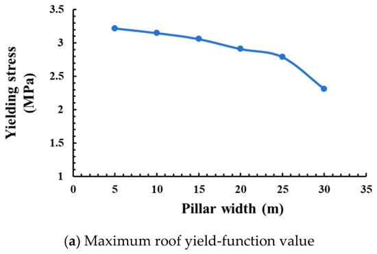
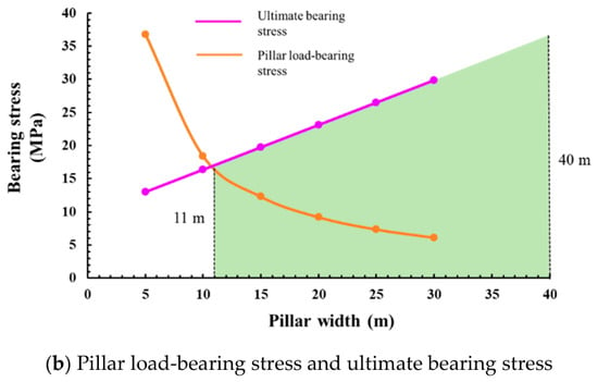
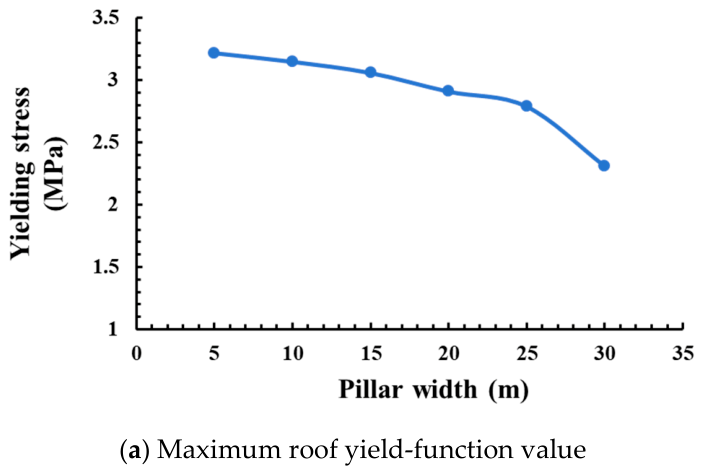
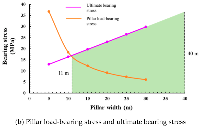
Based on Table 3 and Equation (22), the relationships among the maximum yield-function value, pillar load-bearing stress, and ultimate bearing stress of the coal pillars for different pillar widths are plotted, as shown in Figure 9.
Figure 9.
Relationships among maximum roof yield-function value, pillar load-bearing stress, and ultimate bearing stress at different coal-pillar widths.
As shown in Figure 9, the maximum yield-function value in the roof strata exhibits an overall nonlinear decreasing trend with increasing coal-pillar width. When the pillar width increases from 5 to 20 m, the maximum yield-function value decreases approximately linearly, with an average reduction of about 0.02 MPa for each 1 m increase in pillar width. Once the pillar width exceeds 20 m, the rate of decrease becomes more pronounced, averaging approximately 0.06 MPa/m. In addition, according to Table 3, the vertical position at which the maximum yield-function value occurs gradually shifts downward as the pillar width increases. On average, every 5 m increase in pillar width results in an approximately 1 m decrease in the roof height corresponding to the maximum yield-function value. These results indicate that increasing the coal-pillar width can effectively mitigate yielding failure in the roof strata. Throughout the investigated range, the maximum yield-function value remains well below the average uniaxial compressive strength of the rock mass, i.e., 25 MPa. However, safe upward mining also requires the actual pillar load to remain below the ultimate bearing stress of the coal pillar. Under the investigated conditions, the theoretical minimum pillar width is approximately 11 m, corresponding to the shaded region in Figure 9b; this value should be recalculated for other pillar-goaf geometries and mechanical conditions. Therefore, to facilitate safe upward mining, previous studies by Bai et al. [33]. proposed side-backfilling reinforcement of remnant coal pillars in the goaf, thereby forming a composite “coal pillar–backfill” load-bearing structure. This measure effectively increases the equivalent pillar width and enhances the bearing capacity of the residual pillars, showing considerable potential for engineering application.
4.5. Comparison with Published Evidence and Engineering Applicability
The present study is primarily an analytical investigation aimed at identifying the dominant coupled mechanisms and theoretical safety boundaries for upward re-mining above pillar-supported water-bearing goafs. Direct one-to-one validation of the calculated thresholds requires field datasets containing, simultaneously, the actual remnant-pillar geometry, interburden properties, in situ stress, long-term pillar strength, and time-dependent goaf water pressure. Such a complete dataset is currently unavailable for the investigated case. Therefore, the present results are compared below with published experimental and field observations in terms of the principal mechanical trends rather than by direct reproduction of identical threshold values.
The principal trends predicted by the present model are consistent with previously published experimental and field observations, as shown in Table 4. Previous studies on multi-seam mining with remnant pillars have shown that remnant pillars act as localized stress-concentration sources and that pillar failure can induce load redistribution and progressive instability of adjacent pillars. This supports the present prediction that increasing mining depth raises pillar load-bearing stress and progressively reduces the stability margin of the pillar group. Similarly, experimental studies have demonstrated that water saturation and prolonged water immersion reduce the strength and load-bearing capacity of coal pillars, which is consistent with the water-induced weakening mechanism discussed in Section 2.2. Published investigations of water-filled abandoned goafs further indicate that hydraulic connection through mining-induced fractures can result in floor water-inrush hazards, supporting the upper hydraulic constraint adopted in the present safety evaluation.
Table 4.
Comparison between present theoretical predictions and published observations.
The quantitative thresholds obtained in this study should therefore be interpreted as case-specific theoretical boundaries rather than universal design values. In particular, the safe goaf water-pressure range of 0.72–0.96 MPa results from the simultaneous satisfaction of two case-dependent constraints: the lower bound is controlled by the ultimate bearing capacity of the remnant coal pillars, whereas the upper bound is governed by the floor water-inrush criterion. Likewise, the minimum pillar width of approximately 11 m depends on the adopted mining depth, seam thickness, coal strength, load-bearing-unit width, and hydraulic condition. Changes in these parameters will shift the calculated safety boundaries.
For engineering applications, the proposed framework should therefore be recalibrated using site-specific data. At a minimum, the actual pillar dimensions and spacing, coal and rock mechanical properties, interburden thickness, in situ stress state, mining depth, and goaf water pressure should be determined from field investigation or monitoring. The corresponding parameters should then be substituted into the analytical model to recalculate the pillar bearing condition, interburden failure state, and hydraulic safety boundary. For highly irregular pillar groups, strongly heterogeneous strata, or transient seepage conditions, the analytical results should preferably be supplemented by numerical modeling and field monitoring before being adopted for mine design.
5. Conclusions
- (1)
- Upward re-mining of an overlying coal seam above a goaf supported by residual coal-pillar groups exhibits pronounced multistage damage evolution and progressive instability. Following room-and-pillar extraction of the lower coal seam, individual pillars undergo progressive plastic failure from the goaf-facing boundaries toward their interiors. Boundary pillars and other critical load-bearing pillars are more susceptible to premature instability, and the resulting load redistribution may trigger successive failure of adjacent pillars, ultimately leading to progressive or chain-type instability of the coal-pillar group. Meanwhile, the interburden strata sequentially experience initial mining-induced damage associated with extraction of the lower seam, long-term weakening caused by water immersion and time-dependent creep damage, and renewed disturbance induced by repeated mining of the upper seam, resulting in continuous deterioration of their structural integrity. Whether the mining-induced failure zones associated with the upper and lower coal seams become interconnected, together with the residual thickness of the interburden control layer, constitutes a key structural condition governing both the stability of upward re-mining and the risk of water inrush from the underlying goaf.
- (2)
- A semi-infinite plane mechanical model was developed to account for the combined effects of overburden loading, horizontal in situ stress, support provided by the coal-pillar group, and water pressure within the goaf. Analytical solutions were obtained for the stress field in the interburden strata and the extent of roof yielding under coal-pillar group support. By further integrating the Mohr–Coulomb failure criterion, the ultimate bearing capacity of the coal pillars, and the floor failure depth induced by extraction of the upper seam, a comprehensive framework was established for evaluating the stability of upward re-mining. Parametric analyses indicate that an increase in the lateral pressure coefficient suppresses tensile failure in the goaf roof. With increasing mining depth, both the maximum yield-function value and the pillar load-bearing stress generally increase; however, the pillar load increases more markedly, indicating that the bearing capacity of the residual pillars progressively becomes the dominant constraint on the safety of deep upward re-mining. The critical mining-depth threshold is further reduced when long-term water-induced strength degradation and creep are considered; therefore, the value derived from the unweakened Wilson strength should be regarded as an upper-bound estimate. Increasing the pillar width simultaneously reduces the average pillar load and the degree of roof yielding, thereby enhancing the overall stability of the coupled coal-pillar–interburden system.
- (3)
- Goaf water pressure exerts a distinct dual effect on upward re-mining through competing mechanical and hydraulic mechanisms. On the one hand, water pressure within the goaf can sustain part of the overburden load, thereby reducing the load transferred to the coal pillars and alleviating yielding within the roof strata, which is beneficial to the stability of both the coal-pillar group and the interburden strata. On the other hand, continued increases in water pressure enhance the hydraulic driving force for water inrush through the interburden, thereby increasing the likelihood of water inrush from the underlying goaf. Consequently, the safety of upward re-mining is not controlled by any single factor, but by the coupled constraints imposed by coal-pillar bearing capacity, interburden integrity, and goaf water pressure. A safe operating window therefore exists in which structural stability and water-inrush prevention must be considered simultaneously. Under the investigated conditions, the reasonable goaf water pressure ranges from 0.72 to 0.96 MPa. A minimum pillar width of approximately 11 m is required under the investigated geometric and mechanical conditions. When the goaf water pressure reaches the critical value of 0.96 MPa and the pillar load-bearing stress reaches its ultimate bearing stress, the corresponding critical mining depth of the lower coal seam is approximately 208 m. These findings provide a theoretical basis for the safe recovery of coal resources overlying abandoned goafs supported by residual coal-pillar groups and for the coordinated control of water-inrush hazards associated with water-filled goafs.
It should be emphasized that the quantitative safety thresholds obtained in this study are case-specific theoretical results rather than universal mine-design criteria. The present framework has not yet been independently validated using a complete site-specific monitoring dataset. Therefore, application to other mining sites requires recalibration using local geological, mechanical, geometric, and hydraulic parameters, preferably supplemented by numerical analysis or field monitoring where strongly irregular pillar geometries or complex hydrogeological conditions are involved.
Author Contributions
Conceptualization, K.M.; Data curation, K.M., R.F. and Y.F.; Formal analysis, R.F. and Y.H.; Funding acquisition, K.M., Y.F. and R.Q.; Investigation, Y.H.; Visualization, C.L.; Writing—original draft, K.M.; Writing—review and editing, K.M. All authors have read and agreed to the published version of the manuscript.
Funding
This study was supported by Shanxi Key Laboratory of Dust Occupational Hazard Prevention and Intelligent Equipment Research for Coal Mine Safety (202504010932032), National Natural Science Foundation of China (52504097 and 52304094), Fundamental Research Program of Shanxi Province (202403021221136), Scientific and Technological Achievements Transformation Guidance Project of Shanxi Province (202304021301046), Science and Technology Innovation Project of Higher Education Institutions in Shanxi Province (2025L059), Taiyuan University of Science and Technology Scientific Research Initial Funding (20242145), and Doctoral Starting Foundation of Shanxi Province (20252006).
Data Availability Statement
The data that support the findings of this study are available from the corresponding author upon reasonable request.
Conflicts of Interest
The authors declare no conflicts of interest.
References
- Feng, G.; Zhang, Y.; Qi, T.; Kang, L. Status and research progress for residual coal mining in China. J. China Coal. Soc. 2020, 45, 151–159. (In Chinese) [Google Scholar]
- Qian, R.; Liu, X.; Ma, Q.; Feng, G.; Bai, J.; Guo, J.; Zhang, S.; Wen, X. Effect of water intrusion on mechanical behaviors and failure characteristics of backfill body and coal pillar composite speci-mens under uniaxial compression. J. Clean. Prod. 2025, 502, 145388. [Google Scholar] [CrossRef] [Scilit]
- Li, J.; Yang, T.; Deng, W.; Du, S.; Zhang, Z.; Ma, H.; Wang, H.; Guo, J.; Liu, L. Evaluating failure mechanisms of excavation-induced large-scale landslides in Xinjing open-pit coal mine through integrated UAV imagery and 3D simulation. Landslides 2025, 22, 2021–2036. [Google Scholar] [CrossRef] [Scilit]
- Ma, K.; Yang, T.; Zhao, Y.; Liu, Y.; Gao, Y.; Hou, J.; Deng, W. Theoretical analysis of water inrush from goaf in floor and mining stability for upward repeated mining. J. China Coal. Soc. 2023, 48, 37–46. (In Chinese) [Google Scholar]
- Feng, G.; Zhu, W.; Li, Z.; Bai, J.; Luo, Z. Dynamic collapse mechanism and prevention of shallow-buried pillar group underlying working seam floor in mined-out area. J. China Coal. Soc. 2022, 47, 200–209. (In Chinese) [Google Scholar]
- Feng, G.; Guo, F.; Bai, J.; Zhang, Y.; Qi, T.; Guo, J.; Zhang, M.; Kang, L. Safety mining evaluation of middle abandoned coal seam in “upper pillar-lower longwall” composite mining areas. J. China Coal. Soc. 2017, 42, 2245–2253. (In Chinese) [Google Scholar]
- Wu, Q. Progress, problems and prospects of prevention and control technology of mine water and reutilization in China. J. China Coal. Soc. 2014, 39, 795–805. (In Chinese) [Google Scholar]
- Ma, K.; Yang, T.; Zhao, Y.; Hou, X.; Liu, Y.; Hou, J.; Zheng, W.; Ye, Q. Mechanical model for analyzing the water-resisting key stratum to evaluate water inrush from goaf in roof. Geomech. Eng. 2022, 28, 299–311. [Google Scholar] [CrossRef]
- Yin, S.; Chang, C.; Zhang, M.; Wang, G.; Liu, Q.; Ju, Q. Beyond static fingerprints to dynamic evolution: A CNN-LSTM-Attention model for identifying coal mine water inrush sources in northern China. Processes 2025, 13, 3906. [Google Scholar] [CrossRef] [Scilit]
- Guo, J.; Ma, L. Permeability distribution characteristics and water resistance evaluation of interlayer rock strata during multi-seam coal mining. Mine Water Environ. 2025, 44, 239–258. [Google Scholar] [CrossRef] [Scilit]
- Lu, A.; Song, D.; Li, Z.; Zhou, C.; Wang, P.; He, X. Analysis of rockburst hazard and optimization of prevention and control measures in multi-seam mining based on refined numerical simulations. Bull. Eng. Geol. Environ. 2025, 84, 512. [Google Scholar] [CrossRef] [Scilit]
- Prasanth, D.; Kolikipogu, N.; Ram, S.; Roy, G. Assessment of overlying goaved-out panel effects on continuous miner workings: A numerical modelling and field experience. Sadhana-ACAD. P. Eng. S. 2026, 51, 258. [Google Scholar] [CrossRef] [Scilit]
- Ma, J.; Bai, J.; Cui, B.; Feng, G.; Wang, S.; Shi, X.; Pan, R.; Xun, J.; Fan, Z. Influence mechanism of pillar-side backfilling on the overburden-coal pillar system’s stability under upward mining. Mater. Today Commun. 2025, 44, 112117. [Google Scholar] [CrossRef] [Scilit]
- Hou, X.; Yang, T.; Li, Z.; Sun, Y.; Jin, Y. Types and main characteristics of old goaf water disaster in Shanxi Province. J. Mining. Saf. Eng. 2020, 37, 1009–1018. (In Chinese) [Google Scholar]
- Li, Z.; Feng, G.; Cui, J. Research on the influence of slurry filling on the stability of floor coal pillars during mining above the room-and-pillar goaf: A case study. Geofluids 2020, 2020, 8861348. [Google Scholar] [CrossRef] [Scilit]
- Qian, M.; Shi, P.; Xu, J.; Wu, Y. Mining Pressure and Strata Control; China University of Mining and Technology Press: Xuzhou, China, 2021. [Google Scholar]
- Ghosh, N.; Agrawal, H.; Singh, S.; Banerjee, G. Optimum chain pillar design at the deepest multi-seam longwall workings in India. Mining. Metall. Explor. 2020, 37, 651–664. [Google Scholar] [CrossRef] [Scilit]
- Tan, Y.; Ma, Q.; Liu, X.; Liu, X.; Elsworth, D.; Qian, R.; Shang, J. Study on the disaster caused by the linkage failure of the residual coal pillar and rock stratum during multiple coal seam mining: Mechanism of progressive and dynamic failure. Int. J. Coal. Sci. Technol. 2023, 10, 45. [Google Scholar] [CrossRef] [Scilit]
- Huang, Q.; Du, J.; Chen, J.; He, Y. Coupling control on pillar stress concentration and surface cracks in shallow multi-seam mining. Int. J. Min. Sci. Technol. 2021, 31, 95–101. [Google Scholar] [CrossRef] [Scilit]
- Tian, C.; Yang, X.; Sun, H.; Liu, Y.; Hu, Q. Experimental study on the overburden movement and stress evolution in multi-seam mining with residual pillars. Energy Sci. Eng. 2019, 7, 3095–3110. [Google Scholar] [CrossRef] [Scilit]
- Ma, Q.; Liu, X.; Qian, R.; Tan, Y.; Li, B.; Liu, X. Progressive failure processes and mechanisms of disasters caused by interrelated failure of residual coal pillars and rock strata. Sci. Total Environ. 2024, 954, 176181. [Google Scholar] [CrossRef] [Scilit] [PubMed]
- Qin, Y.; Xu, N.; Zhang, Z.; Zhang, B. Failure process of rock strata due to multi-seam coal mining: Insights from physical modelling. Rock Mech. Rock Eng. 2021, 54, 2219–2232. [Google Scholar] [CrossRef] [Scilit]
- Qu, Q.; Guo, H.; Khanal, M. Monitoring and analysis of ground movement from multi-seam mining. Int. J. Rock Mech. Min. Sci. 2021, 148, 104949. [Google Scholar] [CrossRef] [Scilit]
- Ju, J.; Xu, J. Structural characteristics of key strata and strata behaviour of a fully mechanized longwall face with 7.0 m height chocks. Int. J. Rock Mech. Min. Sci. 2013, 58, 46–54. [Google Scholar] [CrossRef] [Scilit]
- Kang, Q.; He, F.; Yin, S.; Yang, Y. Attenuation law of concentrated stress under coal pillar of close coal seams and its application. Sci. Rep. 2022, 12, 21753. [Google Scholar] [CrossRef] [Scilit] [PubMed]
- Song, C.; Lu, C.; Zhang, X.; Wang, C.; Xie, H.; Yan, X.; Yang, H. Moment tensor inversion and stress evolution of coal pillar failure mechanism. Rock Mech. Rock Eng. 2022, 55, 2371–2383. [Google Scholar] [CrossRef] [Scilit]
- Kadkhodaei, M.H.; Ghasemi, E.; Zhou, J.; Zahraei, M. Evaluation of underground hard rock mine pillar stability using gene expression programming and decision tree-support vector machine models. Deep Undergr. Sci. Eng. 2025, 4, 18–34. [Google Scholar] [CrossRef] [Scilit]
- Qi, H.; Qiu, Y.; Zhou, J. Pillar stability assessment in deep mining using a stacked ensemble model with interpretable features. Rock Mech. Rock Eng. 2026. [Google Scholar] [CrossRef] [Scilit]
- Wang, N.; Zhao, G.; Wang, M.; Pattela, T. Explainable hybrid stacking ensemble method for hard rock pillar stability prediction and engineering applications. Deep Undergr. Sci. Eng. 2026, 1–19. [Google Scholar] [CrossRef] [Scilit]
- Zvarivadza, T.; Grobler, H.; Olubambi, P.A.; Onifade, M.; Khandelwal, M. Advancing mine pillar design: Evaluating traditional methods and integrating AI for enhanced stability of pillars in the Great Dyke, Zimbabwe. Deep Undergr. Sci. Eng. 2026, 5, 933–955. [Google Scholar] [CrossRef] [Scilit]
- Ma, K.; Yang, T.; Deng, W.; Hou, X.; Li, Z.; Zhao, Y.; Liu, Y.; Gao, Y.; Sun, D.; Hou, J. Analysis of water inrush at Dongyu coal mine in China from an old water-logged goaf associated with a syncline fractured zone. Hydrogeol. J. 2023, 31, 417–433. [Google Scholar] [CrossRef] [Scilit]
- Feng, G.; Bai, J.; Shi, X.; Qi, T.; Wang, P.; Guo, J.; Wang, S.; Kang, L. Key pillar theory in the chain failure of residual coal pillars and its application prospect. J. China Coal. Soc. 2021, 46, 164–179. (In Chinese) [Google Scholar]
- Bai, J.; Cui, B.; Qi, T.; Zhu, W.; Wang, K.; Shi, X.; Wu, H.; Kang, L. Fundamental theory for rock strata control of key pillar-side backfilling. J. China Coal. Soc. 2021, 46, 424–438. (In Chinese) [Google Scholar]
- Poulsen, B.; Shen, B.; Williams, D.; Huddlestone-Holmes, C.; Erarslan, N.; Qin, J. Strength reduction on saturation of coal and coal measures rocks with implications for coal pillar strength. Int. J. Rock Mech. Min. Sci. 2014, 71, 41–52. [Google Scholar] [CrossRef] [Scilit]
- Fan, J.; Li, Z.; Feng, G.; Zhang, H.; Qi, C.; Zhang, J. Failure analysis of coal pillars and overburden from underground water reservoir under the mining-water invasion coupling effect. Eng. Fail. Anal. 2023, 151, 107406. [Google Scholar] [CrossRef] [Scilit]
- Shi, Z.; Zhu, G.; Zi, Z. Research on water immersion damage characteristics and equivalent width of coal pillar. Sci. Rep. 2024, 14, 31456. [Google Scholar] [CrossRef] [Scilit] [PubMed]
- Zhang, Y.; Yang, J.; Zhang, J.; Sun, X.; Chen, C.; Zheng, X.; Xu, H. Modeling the spatial and temporal evolution of stress during multiworking face mining in close distance coal seams. Adv. Civ. Eng. 2021, 2021, 5624972. [Google Scholar] [CrossRef] [Scilit]
- Yin, L.; Ma, K.; Chen, J.; Xue, Y.; Wang, Z.; Cui, B. Mechanical model on water inrush assessment related to deep mining above multiple aquifers. Mine Water Environ. 2019, 38, 827–836. [Google Scholar] [CrossRef] [Scilit]
- Li, J.; Gao, Y.; Yang, T.; Zhang, P.; Zhao, Y.; Deng, W.; Liu, H.; Liu, F. Integrated simulation and monitoring to analyze failure mechanism of the anti-dip layered slope with soft and hard rock interbedding. Int. J. Min. Sci. Technol. 2023, 33, 1147–1164. [Google Scholar] [CrossRef] [Scilit]
- Liang, Z.; Song, W.; Liu, W. Theoretical models for simulating the failure range and stability of inclined floor strata induced by mining and hydraulic pressure. Int. J. Rock Mech. Min. Sci. 2020, 132, 104382. [Google Scholar] [CrossRef] [Scilit]
- Wilson, A. An hypothesis concerning pillar stability. Min. Eng. 1972, 131, 409–417. [Google Scholar]
- Wu, F.; Du, J.; Sun, F.; Chen, G.; Jiang, F.; Zhu, Z. Multi-method coal seam floor water inrush risk evaluation based on variable weight theory. Energy Explor. Exploit. 2025, 43, 724–743. [Google Scholar] [CrossRef] [Scilit]

Disclaimer/Publisher’s Note: The statements, opinions and data contained in all publications are solely those of the individual author(s) and contributor(s) and not of MDPI and/or the editor(s). MDPI and/or the editor(s) disclaim responsibility for any injury to people or property resulting from any ideas, methods, instructions or products referred to in the content. |
© 2026 by the authors. Licensee MDPI, Basel, Switzerland. This article is an open access article distributed under the terms and conditions of the Creative Commons Attribution (CC BY) license.