


Abstract
Thermochemical energy storage technology offers an effective approach to address the intermittency and instability of solar energy supply, thereby enhancing its utilization efficiency and reducing dependence on fossil fuels. The CaCO3/CaO system provides a low-cost, abundant, and safe thermal energy storage solution with high energy density, suitable for large-scale use. However, the low effective thermal conductivity of the storage material in fixed-bed reactors often leads to limited heat transfer performance. To address this issue, this study investigates the internal temperature distribution and reaction field in a finned reactor, with a focus on the effects of fin geometry (including layout, number, and dimensions) on the carbonation reaction performance. The results demonstrate that the incorporation of fins significantly enhances heat transfer within the reactor. Hor-izontal fins increased the reaction rate by 11.81%, while vertical fins resulted in a more pronounced improvement of 41.17%. Furthermore, variations in fin structural parameters markedly influenced the carbonation process. Increasing the number of vertical fins from four to eight improved the reaction rate by 24.23%. Under the conditions studied, the optimal fin configuration, with a thickness of 0.002 m, a length of 0.03 m, and a total of eight fins, achieved the shortest carbonation time. This study provides valuable insights into the design of efficient reactor structures for enhanced thermochemical energy storage.
1. Introduction
The transition towards a renewable energy-dominated system is imperative for achieving carbon peak and neutrality targets [1,2]. Solar energy, renowned for its abundance and sustainability, stands out as a leading renewable resource. Concentrated solar power (CSP), which converts solar energy into electricity through a thermodynamic cycle, is a major utilization pathway [3,4,5]. However, the inherent intermittency and volatility of solar energy lead to spatiotemporal mismatches between supply and demand [6,7]. Thermal energy storage (TES) is therefore critical for ensuring a stable and continuous energy supply from solar sources [8,9,10].
TES technologies are broadly classified into thermophysical storage (sensible and latent heat) and thermochemical energy storage (TCES). Compared to thermophysical methods, TCES offers superior energy storage density, higher operating temperatures, and longer storage durations, making it a promising direction for efficient, large-scale solar thermal storage [11]. The performance of TCES systems fundamentally depends on the choice of storage materials. Various reaction systems have been explored, including metal oxides, hydrides, hydroxides, carbonates, sulfates, methane reforming, and am-moniate systems [12,13], each with distinct trade-offs in cost, energy density, and reaction temperature. Among these, the calcium carbonate (CaCO3/CaO) system is particularly attractive due to its low cost, non-toxicity, high energy density, and high operating temperature [14].
Conventional CaCO3 sources include natural minerals (e.g., limestone, dolomite) and calcium-rich industrial wastes (e.g., steel slag, carbide slag) [15,16,17]. Nevertheless, the system faces material-level challenges, notably the tendency of CaCO3/CaO to sinter at high temperatures. This sintering causes pore collapse, grain growth, and a severe reduction in porosity, leading to diminished reaction activity and poor cyclic stability over multiple charging–discharging cycles [15,16]. Co-doping has been widely investigated as an effective method to mitigate these issues and enhance overall performance [18,19,20].
However, a more fundamental application-level challenge remains: the low thermal conductivity of both CaO and CaCO3, which severely limits heat transfer within the reactor. This results in sluggish reaction kinetics, long cycle durations, and ultimately impaired system efficiency and economic viability [21,22]. To address this, several heat transfer enhancement strategies have been proposed, including (1) developing composite materials with high-conductivity additives (e.g., expanded graphite, metal foam) [23,24]; (2) optimizing reactor geometry (e.g., multi-tubular, honeycomb designs) to increase surface area [25,26]; and (3) embedding high-thermal-conductivity fins to extend heat transfer surfaces [27,28]. Among these, fin integration has gained significant attention owing to its structural simplicity, ease of manufacture, and notable effectiveness.
Previous studies have demonstrated the potential of fins in various TCES systems. Ranjha et al. [29] used copper fins to enhance heat transfer and reduce reaction time in a high-temperature reactor. Ye et al. [30] reported a 25.3% reduction in charging time for an Mg(OH)2/MgO system with a 3D cross-arranged fin design. Recently, topology optimization (TO), a computational design method used to generate efficient structures, has been introduced to the TES field [31,32]. Its application has led to groundbreaking designs: Zhang et al. [33] used TO to design a novel fin structure for a K2CO3 reactor, improving temperature uniformity and power output; Chen et al. [34] designed a TO-optimized multi-tube reactor fin that reduced reaction time by 43% compared to conventional fins; and Humbert et al. [35] applied a novel topology optimization framework to design innovative fin structures for a closed SrBr2 reactor, which resulted in a performance improvement of up to +286% in discharge energy compared to state-of-the-art designs. The feasibility of such complex designs has been further validated by Ge et al. [36] through additive manufacturing.
Shi et al. [37] designed a thermochemical heat storage reactor model based on Schaube’s experimental setup for the numerical simulation of the dehydration and hydration processes of Ca(OH)2. By integrating heat transfer fluid channels and metal fins within the reactor, their results demonstrated that the optimized structure significantly enhanced cooling performance, reducing the reaction time by 90%. In addition to using metal fins to improve reaction efficiency, Mathew et al. [38] developed a directly heated reactor equipped with cylindrical graphite fins for the exothermic carbonation process of CaO. Their findings indicated that the incorporation of graphite fins reduced the carbonation reaction time by approximately 44%. However, the authors did not account for the effects of fluid flow in their simulations. Han et al. [39] designed a reactor using zeolite as the thermochemical material for experimental purposes and compared the performance of reactors with and without copper fins. The results showed that adding copper fins increased the energy storage density by 105 kWh/m3 and improved energy utilization efficiency by 5%. These findings provide valuable insights for enhancing reactor performance. Chen et al. [34] compared the effects of fins made of aluminum, copper, and stainless steel on reactor performance. Among these, copper has the highest thermal conductivity, while stainless steel has the lowest. Their study revealed that higher fin thermal conductivity leads to more uniform reactions within the reactor.
Despite these advancements, existing research on fin-assisted TCES reactors has predominantly focused on salt hydrate or hydroxide systems [40,41,42,43]. The optimization of fins specifically for high-temperature CaCO3/CaO reactors has rarely been explored. Moreover, a systematic quantification of the impact of key fin parameters (e.g., layout, number, thickness, material distribution) on reactor performance is still lacking.
Therefore, this study aims to bridge this gap by systematically investigating the effects of fin configuration and structural parameters on the exothermic performance of a CaCO3/CaO thermochemical storage reactor. Using coupled multi-physics numerical simulations in COMSOL Multiphysics v5.3, the influence of parameters such as fin layout, number, and thickness on temperature distribution and reaction kinetics will be quantitatively analyzed. The findings are expected to provide crucial theoretical insights and design guidelines for developing high-performance CaCO3/CaO thermal energy storage systems.
2. Model Description
2.1. Physical Model
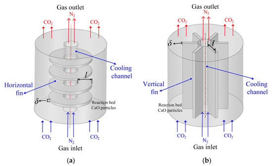
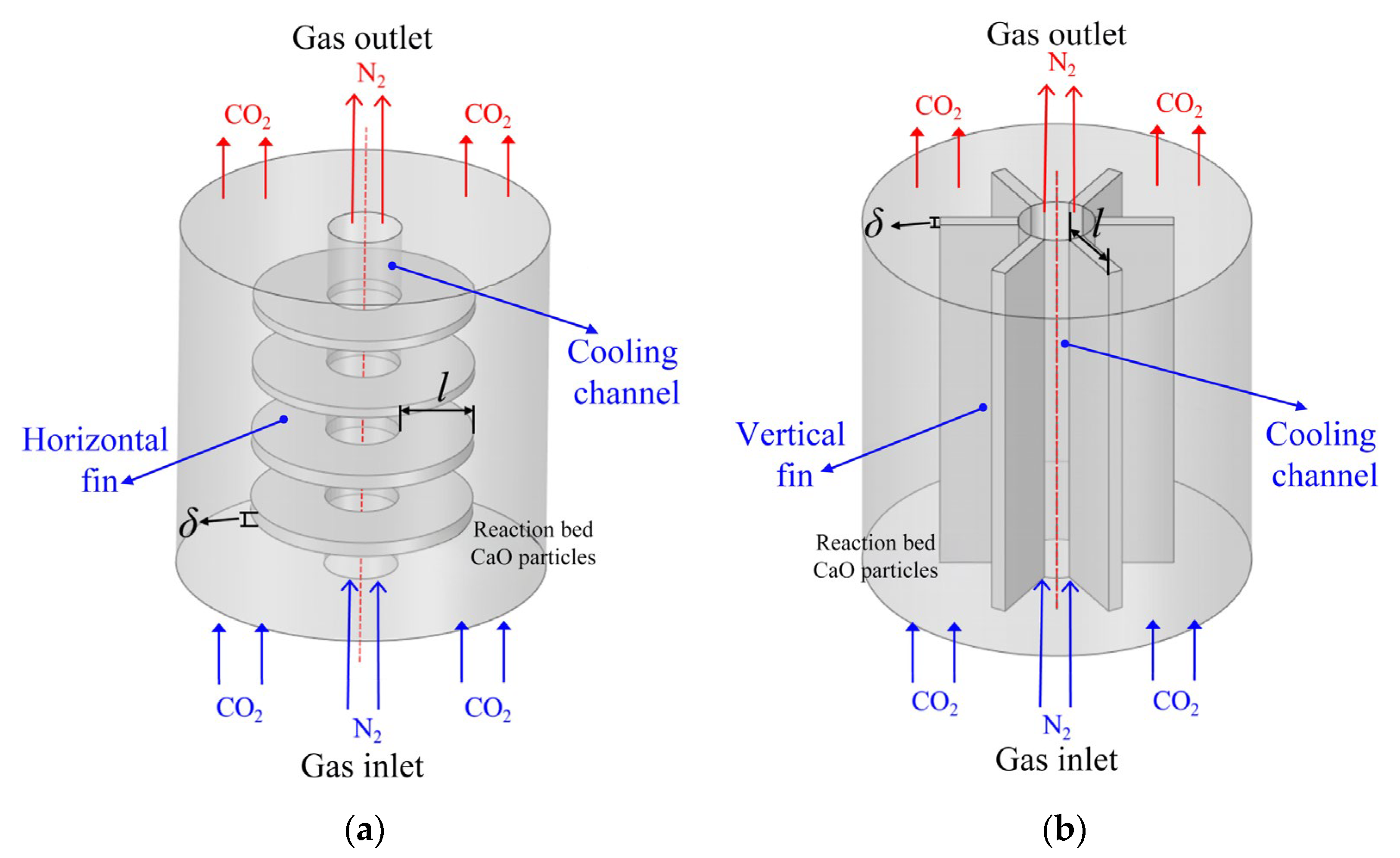
To enhance heat transfer performance within the reactor, a CaCO3/CaO thermos-chemical reactor equipped with horizontal and vertical fins was developed in this study, based on the reactor structure described in published articles [44]. A schematic of the reactor is presented in Figure 1. The model reactor, constructed of stainless steel, has a height of 0.1 m and a radius of 0.05 m. As illustrated in Figure 1a, four horizontal fins, each 0.02 m in length and 0.001 m thick, are incorporated with an inter-fin spacing of 0.02 m. Given traditional solid metal fins would increase the pressure drop inside the reactor, thereby influencing gas flow and overall reactor efficiency, porous materials are adopted for the fins in this study. The fins are modeled as porous media and are assumed to be chemically inert. Figure 1b shows six vertical fins, each 0.03 m long and 0.002 m thick, distributed uniformly around the cooling channel. The relevant physical parameters of the fins are summarized in Table 1.
Figure 1.
Schematic of the reactor models: (a) horizontal fin configuration; (b) vertical fin configuration.
Table 1.
Physical parameters of reactor fins.
In a CaCO3/CaO thermochemical energy storage system, the fixed-bed reactor functions as a reactor for thermochemical heat storage via the reaction between solid particles (CaCO3 or CaO) and CO2 gas. The heat transfer process encompasses gas–solid convection, conduction within the solid particles, inter-particle thermal exchange, and radiative transfer. Heat is convectively transferred from the gas to the particle surfaces and then propagates inward through thermal conduction, promoting temperature uniformity across the bed. Direct particle-to-particle contact also provides a heat conductive pathway. At elevated temperatures, radiative heat transfer between particles becomes significant. Fins integrated into the fixed-bed reactor enhance thermal performance by increasing the effective heat transfer area, which improves convective heat transfer efficiency, promotes uniform gas distribution, and accelerates heat propagation throughout the bed. These modifications collectively elevate the overall thermal efficiency of the reactor, mitigate temperature non-uniformity, and support stable, efficient operation.
2.2. Mathematical Model
2.2.1. Assumption
This study addresses a multi-physical field coupling problem involving chemical reaction kinetics, mass transfer, fluid flow, and energy transport within porous media. Given the complexity of the physical model, the reactor structure is simplified, and the following assumptions are made to facilitate numerical simulation:
- (1)
- CO2 gas is treated as an ideal gas during the carbonation reaction.
- (2)
- A local thermal equilibrium model is applied between CO2 and the reactive bed medium.
- (3)
- The porosity and permeability of the bed medium remain constant throughout the reaction.
- (4)
- The thermal conductivity of CaCO3/CaO is considered temperature-independent.
- (5)
- Radiation heat transfer is neglected in the carbonation process.
2.2.2. Governing Equation
Since similar modeling approaches have been well-established in previous works [44], and based on the above assumptions, the governing equations (including those for gas mass continuity, gas momentum, energy conservation in the reaction bed, and reaction kinetics) are only briefly presented and summarized in Table 2.
Table 2.
Governing equations during the operation of CaCO3/CaO thermochemical exothermic reactor.
2.3. Initial and Boundary Conditions
Temperature and pressure in the reaction process are functions of time and spatial position, denoted as and . Initially, the temperature of the reaction bed equals that of the reactor wall. The initial conditions can be expressed as follows:
At the reactor inlet, the carbon dioxide gas enters with uniform temperature and velocity. The corresponding inlet boundary conditions are expressed as follows:
At the outlet, the boundary is assumed adiabatic (no heat exchange with the surroundings), the export temperature gradient is zero, and the export pressure is 1 × 10⁵ Pa. The outlet boundary condition is described as follows:
Here, n denotes the outward normal direction to the boundary.
2.4. Physical Properties
In this study, CaO serves as the heat transfer medium within the reactor. The physical parameters of the reaction materials and key operating parameters are shown in Table 3.
Table 3.
Physical parameters and operational parameters of reactants in CaCO3/CaO thermochemical exothermic reactor [47,48].
3. Results and Discussion
In this study, the carbonation duration is defined as the time required to reach an average conversion of 0.95, based on the consideration that the majority of heat release has occurred by this point and the remaining heat proportion is negligible. This definition is adopted to facilitate a more intuitive analysis of the impact of reactor structure on performance [37].
3.1. Influence of Horizontal Fins on Reactor Performance
3.1.1. Basic Situation After Fin Placement
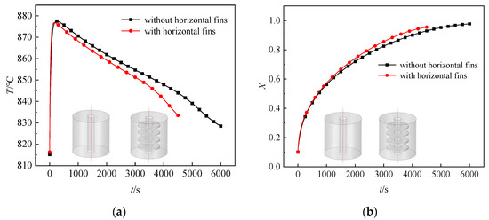
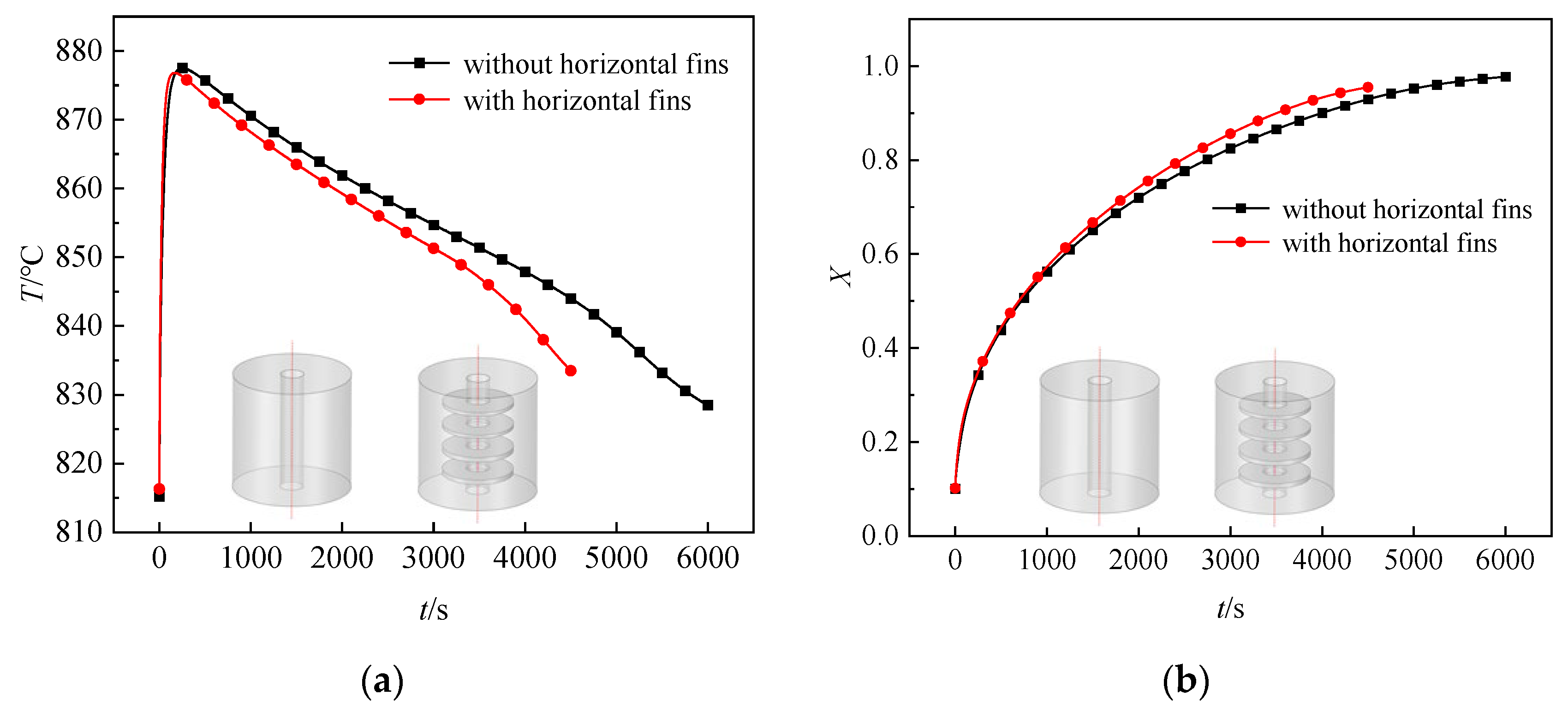
As shown in the comparative curves of average temperature in reactors with and without horizontal fins in Figure 2a, the temperature inside the reactor increases rapidly at the beginning of the reaction and gradually decreases as heat is transferred among the reaction bed, wall, cooling channels, and fins. Compared with the finless configuration, the finned reactor exhibits an overall reduction in temperature. Similarly, the conversion rate curves in Figure 2b indicate that at any given time, the finned reactor achieves a higher conversion rate than that without fins. After the installation of fins, the carbonation duration in the reactor was reduced to 4362 s, compared to 4946 s for the reactor without fins, which is 584 s shorter than that of the unfinned reactor, corresponding to an 11.81% increase in reaction rate. Therefore, the use of horizontal fins effectively enhances heat dissipation within the reactor, thereby improving the efficiency of the carbonation process.
Figure 2.
Effect of horizontal fins on (a) reactor temperature; (b) reactor conversion rate.
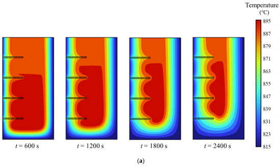
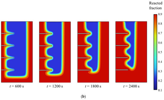
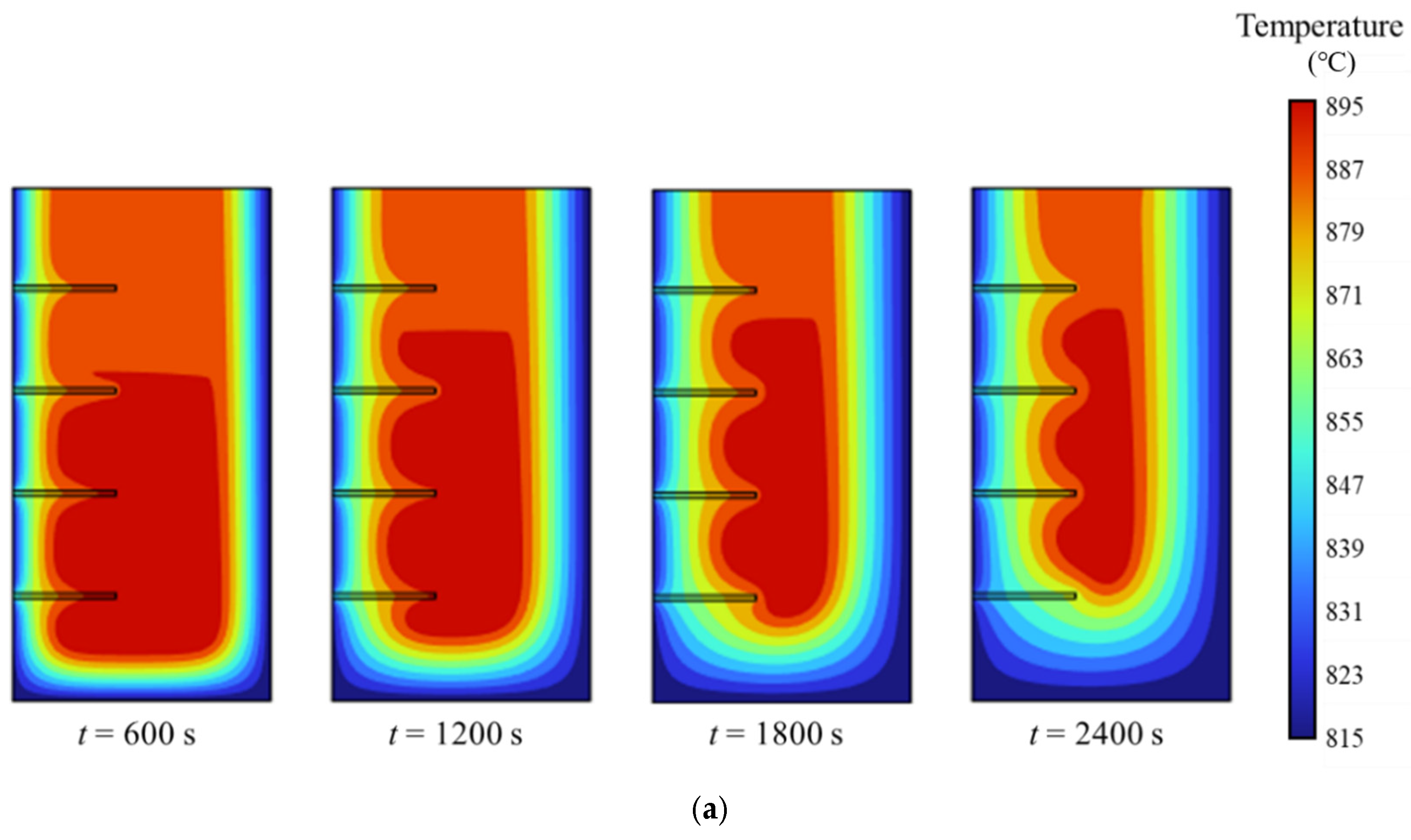
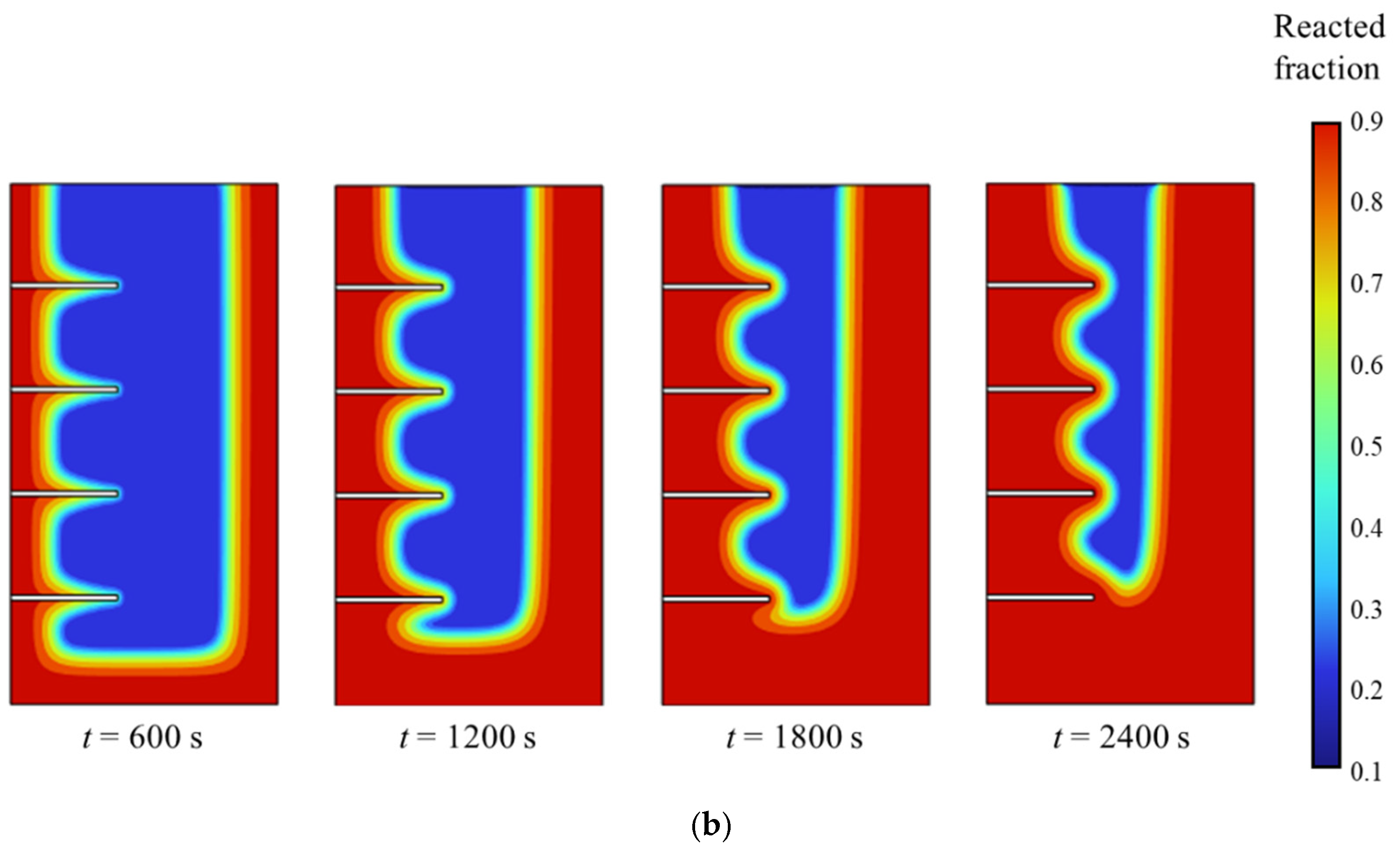
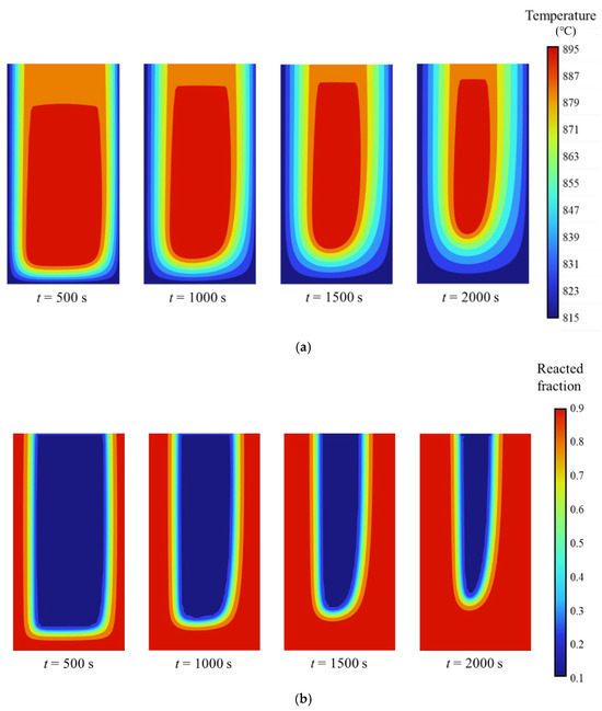
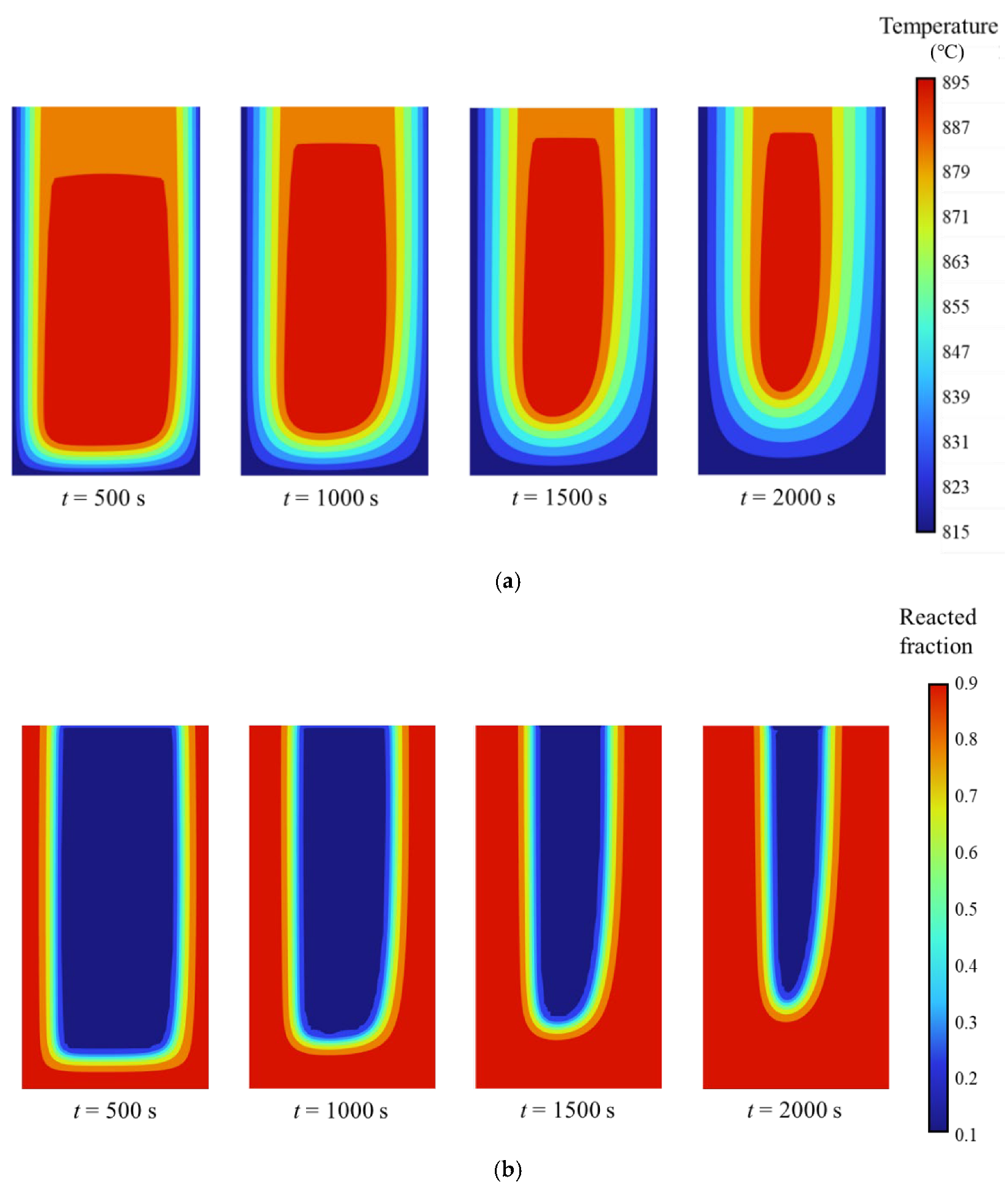
Figure 3a presents the simulated temperature distribution within the reactor equipped with horizontal fins at different time points. The results clearly show that temperatures near the wall are significantly lower than those in regions farther from the wall. The areas around the fins experience cooling first, followed by a gradual temperature decrease in the regions between adjacent fins. Similarly, the spatial evolution of the conversion rate at different times is illustrated in Figure 3b. Higher conversion rates are observed near the wall and around the fins, where the reaction initiates earlier, while the reaction in the inter-fin regions progresses more gradually. These results demonstrate that the incorporation of horizontal fins improves the uniformity of temperature distribution and enhances heat dissipation within the reactor.
Figure 3.
Numerical simulation results in a reactor with horizontal fins, showing the distributions of (a) temperature; (b) conversion rate.
Building upon the findings that demonstrate the enhanced thermal performance contributed by horizontal fins, a parametric study was conducted to evaluate the effects of fin thickness, length, and number. This analysis aims to determine the influence of these geometric parameters on the carbonation process and overall reactor performance.
3.1.2. Influence of Fin Thickness on Reactor Performance
This section investigates the influence of fin thickness, specifically 0.001 m, 0.002 m, and 0.003 m, on the carbonation performance of the reactor. The study was conducted under fixed operational conditions including an inlet flow rate of 0.003 m/s, an initial reactor temperature of 815 °C, a fin length of 0.02 m, and a total of four fins.
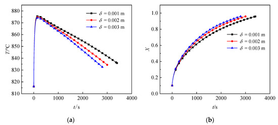
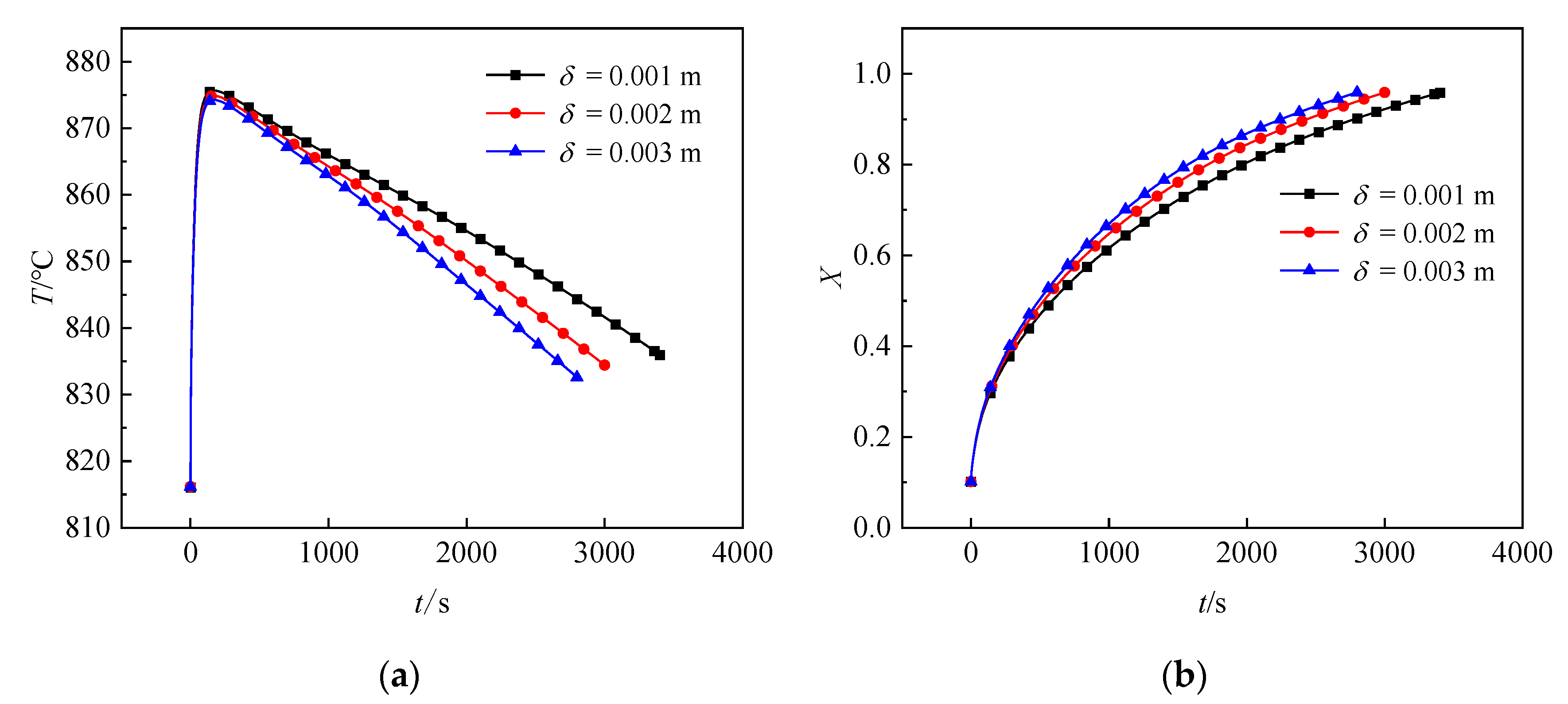
As depicted in Figure 4a, which compares the average temperature profiles across reactors with varying fin thicknesses, the internal temperature trends remain consistent. Larger fin thicknesses correlate with a lower average reactor temperature and a more rapid temperature decrease upon completion of the calcium carbonate reaction. Figure 4b illustrates the effect of fin thickness on conversion rate, indicating that, at any given time, thicker fins correspond to higher conversion rates. Compared to the reactor with a fin thickness of 0.001 m, the configuration with 0.002 m fins exhibited a reduction in carbonation time of 348 s and an increase in reaction rate of 7.98%, while the 0.003 m fin case showed a reduction of 574 s and a rate improvement of 13.16%. This enhancement is attributed to the superior thermal conductivity of the metallic fins relative to the solid reactant material. Increasing fin thickness improves conductive heat transfer within the reactor, thereby accelerating the carbonation process.
Figure 4.
Effect of horizontal fin thickness on (a) reactor temperature; (b) reactor conversion rate.
3.1.3. Influence of Fin Length on Reactor Performance
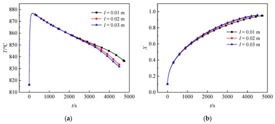
This section examines the influence of horizontal fin length on the carbonation process performance under fixed operating conditions: an inlet flow rate of 0.003 m/s, an initial reactor temperature of 815 °C, a fin thickness of 0.001 m, and four fins. Three fin lengths of 0.01 m, 0.02 m, and 0.03 m were evaluated.
As shown in Figure 5a, which presents the average reactor temperature under different fin lengths, the temperature rises rapidly upon reaction initiation. The differences among the configurations are negligible before 2000 s. Beyond this point, temperature variations become more evident, with longer fins resulting in lower internal temperatures.
Figure 5.
Effect of horizontal fin length on (a) reactor temperature; (b) reactor conversion rate.
Figure 5b shows the corresponding conversion rates under each fin length. Although the effect of fin length is relatively moderate, longer fins consistently lead to shorter carbonation times and higher conversion rates at any given time. Compared to the reactor with a fin length of 0.01 m, the configuration with 0.02 m fins reduced the carbonation time by 336 s and increased the reaction rate by 7.15%, while the 0.03 m fin case achieved a reduction of 426 s and a rate increase of 9.06%.
These results indicate that increasing the length of the horizontal fins enhances heat transfer and accelerates the carbonation process, thereby improving overall reactor performance.
3.1.4. Influence of Fin Number on Reactor Performance
The effect of fin number on the carbonation process was investigated under the following constant conditions: an inlet flow rate of 0.003 m/s, an initial reactor temperature of 815 °C, a fin thickness of 0.001 m, and a fin length of 0.02 m. Three configurations with four, six, and eight fins were studied, corresponding to inter-fin spacings of 0.02 m, 0.012 m, and 0.0086 m, respectively.
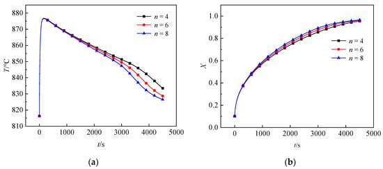
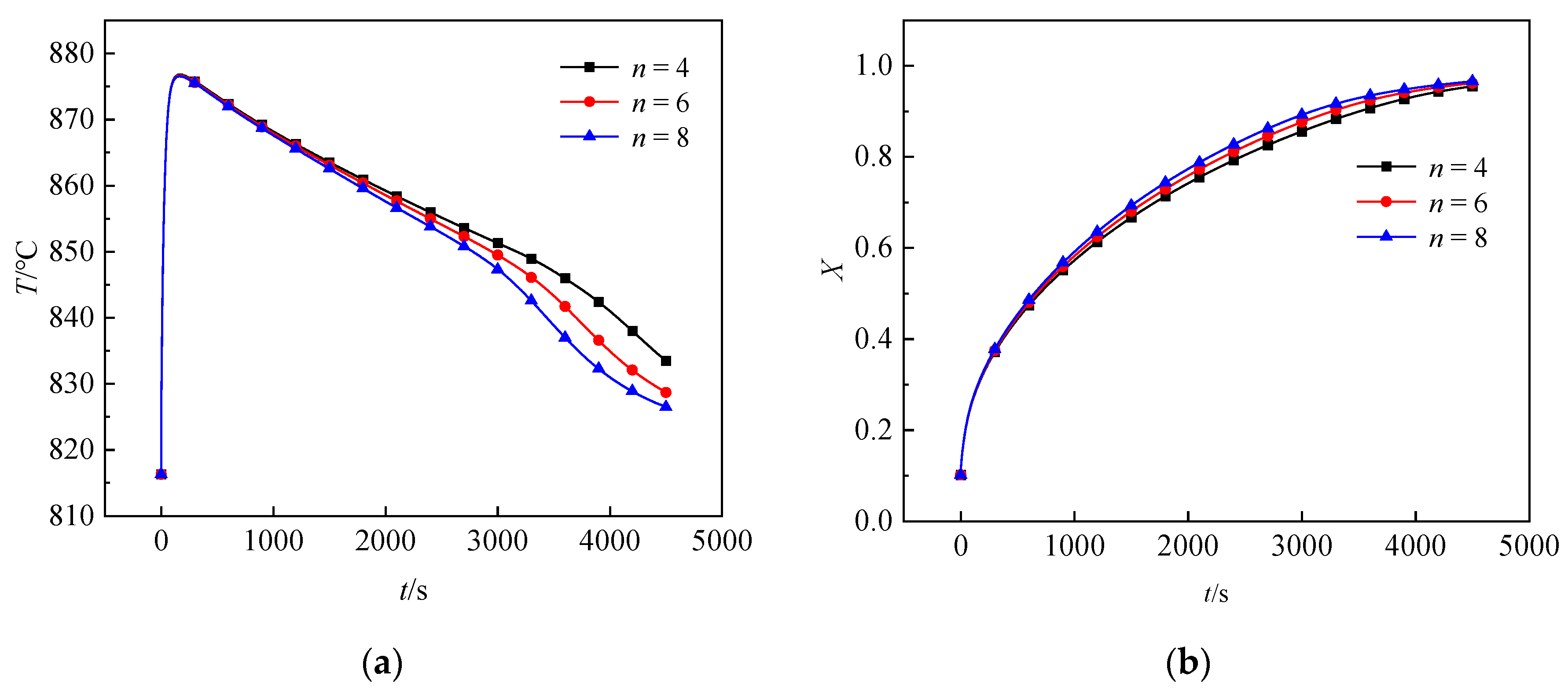
Figure 6a shows the average temperature profiles for reactors with varying numbers of fins. During the initial reaction stage, temperature differences between the configurations are negligible. As heat transfer between the fins and cooling channels intensifies, reactors with more fins exhibit lower average temperatures. Figure 6b illustrates the conversion rate trends under different fin numbers. Although the overall trends are similar, reactors with more fins achieve higher conversion rates and shorter carbonation times. Compared to the configuration with four fins, the reactor with six fins reduced the carbonation time to 4122 s, corresponding to a reduction of 240 s and a 5.5% increase in reaction rate. The reactor with eight fins further shortened the carbonation time to 3954 s, which is a reduction of 408 s, with a 9.35% increase in reaction rate.
Figure 6.
Effect of the number of horizontal fins on (a) reactor temperature; (b) reactor conversion rate.
These results demonstrate that increasing the number of horizontal fins improves heat transfer within the reactor, accelerates the carbonation process, and enhances overall reactor performance.
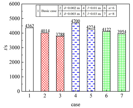
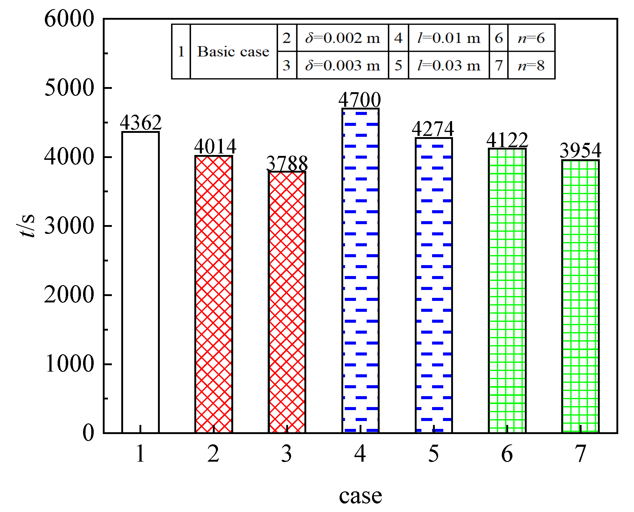
Figure 7 summarizes the influence of various fin dimensions on the carbonation process within the reactor. The results clearly demonstrate that increases in fin thickness, length, and number improve heat dissipation, accelerate the carbonation reaction, and shorten the duration required for complete reactant conversion. For the basic case, the horizontal fins had the following dimensions: a thickness of 0.001 m, a length of 0.02 m, and a number of four. Subsequent cases were developed by varying one of these parameters. Among the configurations evaluated, Case 3, with a fin thickness of 0.003 m, length of 0.02 m, and four fins, exhibited the shortest carbonation time. In contrast, Case 4, which employed fins measuring 0.001 m in thickness and 0.01 m in length with a total of four fins, resulted in the longest carbonation time.
Figure 7.
Effect of different-sized horizontal fins on carbonation process of a reactor.
3.2. Influence of Vertical Fins on Reactor Performance
3.2.1. Basic Situation After Fin Placement
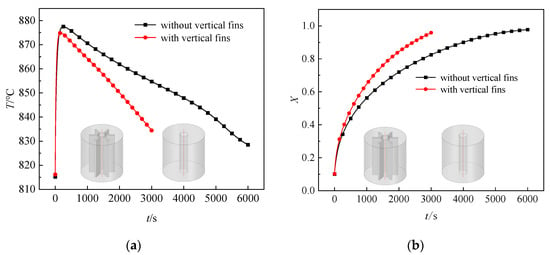
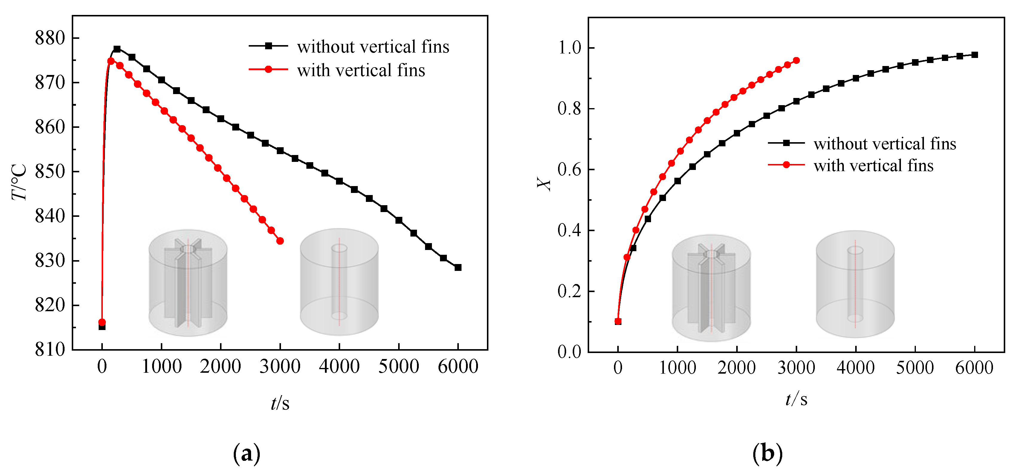
Figure 8a illustrates the effect of incorporating vertical fins on the average temperature of the reactor. During the initial reaction phase, the temperature rises rapidly in both configurations. The reactor equipped with vertical fins attains a slightly lower peak temperature compared to the finless configuration, and the thermal disparity between the two becomes more pronounced over time. As shown in Figure 8b, the finned reactor achieves a significantly higher conversion rate and faster reaction kinetics than the reactor without fins, owing to improved heat conduction resulting from the addition of vertical fins. As the reaction progresses, the rate of heat release from the carbonation reaction diminishes and becomes substantially lower than the rate of heat transfer within the reactor. This leads to a more rapid temperature decrease in the finned reactor, thereby amplifying the overall temperature difference between the two configurations. The carbonation time for the reactor with vertical fins is 2910 s, corresponding to a 41.17% increase in reaction rate compared to the finless case. These results confirm that the use of vertical fins enhances heat dissipation and improves overall reaction performance.
Figure 8.
Effect of vertical cooling fins on (a) reactor temperature; (b) reactor conversion rate.
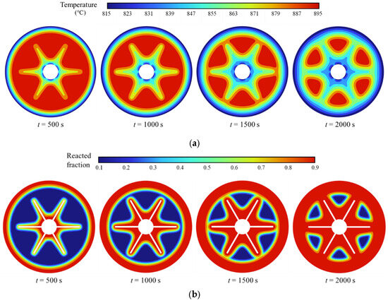
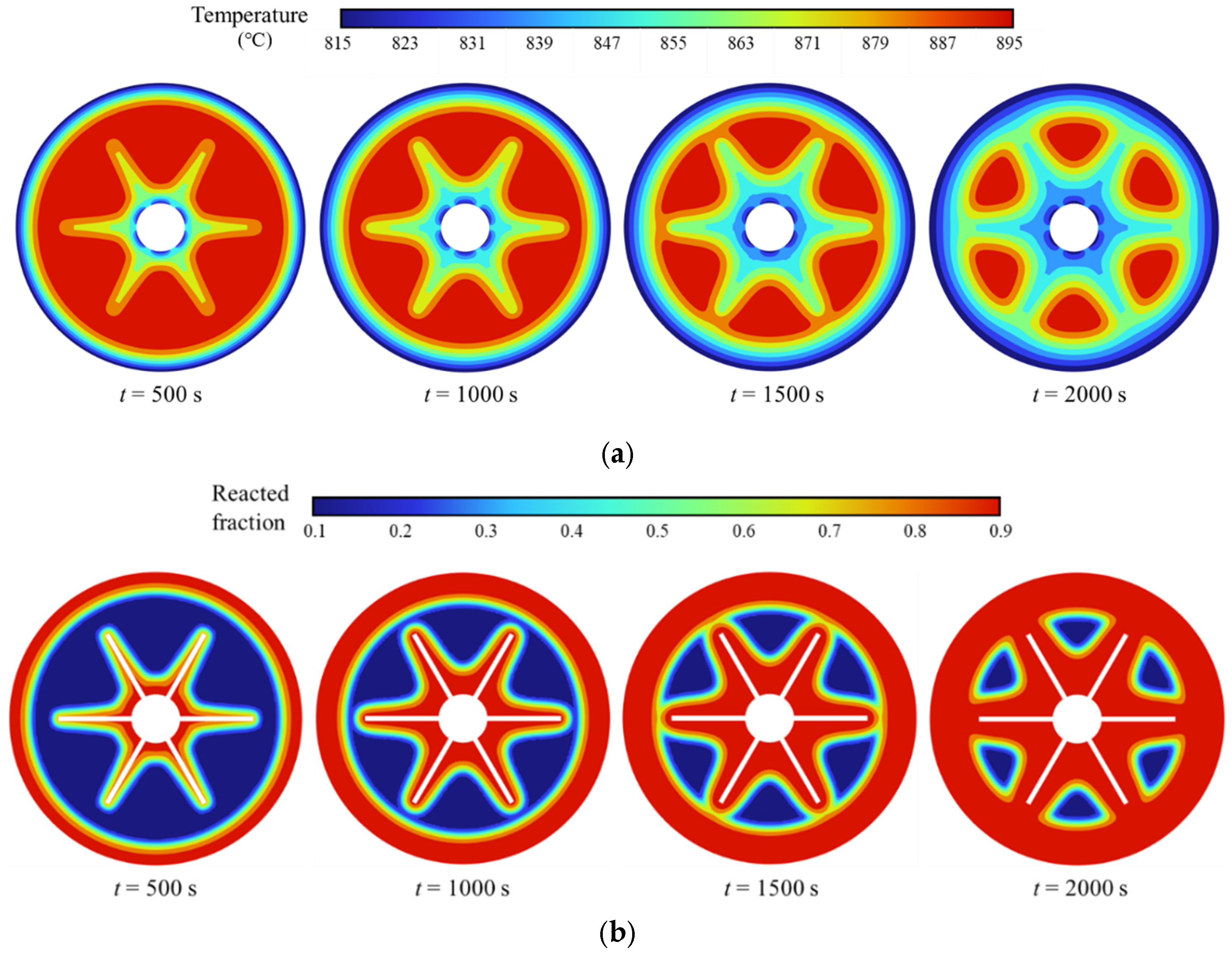
The simulated temperature distribution on the reactor cross-section at z = 0.05 m after incorporating vertical fins is presented in Figure 9a. Regions near the outer wall and adjacent to the fins exhibit lower temperatures compared to areas between the fins. Over time, the cooling propagates inward from the outer surface and outward from the fins toward the central regions. The corresponding conversion rate distribution on the same cross-section is shown in Figure 9b. Reactants in proximity to the wall and fins are consumed first. Due to the combined heat transfer effects from the fins, cooling channels, and reactor wall, both the high-temperature zones and regions of incomplete reaction are progressively reduced. These results demonstrate that the implementation of vertical fins effectively addresses the challenges of low thermal conductivity and poor reaction efficiency within the reactor system.
Figure 9.
Numerical simulation results at the z = 0.05 m cross-section for different times show the distributions of (a) temperature; (b) conversion rate.
Numerical simulations of temperature and conversion rate at the corners of adjacent vertical fins, presented in Figure 10, reveal a distinct shift in the characteristic bowl-shaped distribution of these variables toward the outer wall when compared to the case with cooling channels alone. This redistribution results from the greater heat transfer from the cooling channels and fins into the reactor interior relative to that from the outer wall. Consequently, regions near the central channel exhibit moderately lower temperatures and higher reaction rates than those adjacent to the outer wall.
Figure 10.
Numerical simulation results in a reactor with vertical fins, showing the distributions of (a) temperature; (b) conversion rate.
Building upon the aforementioned findings, which confirm that the incorporation of vertical fins markedly improves heat transfer in the CaCO3/CaO thermochemical exothermic reactor, this section proceeds to evaluate the influence of vertical fin geometry on carbonation performance by varying fin thickness, length, and number.
3.2.2. Influence of Fin Thickness on Reactor Performance
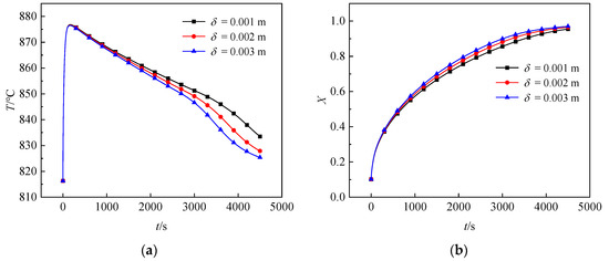
The effect of fin thickness on reactor performance was examined under conditions where the vertical fin length and number were held constant at 0.03 m and six, respectively. Three fin thicknesses were evaluated: 0.001 m, 0.002 m, and 0.003 m. Figure 11a shows that the average temperature profiles follow similar trends across all configurations, with thicker fins resulting in lower average reactor temperatures. Furthermore, Figure 11b indicates that increased fin thickness leads to higher conversion rates, which can be attributed to the superior thermal conductivity of the metallic fins relative to the solid reactants. Enhanced fin thickness improves conductive heat transfer within the reactor. When the fin thickness was 0.001 m, the total reaction time required was 3303 s. Increasing the thickness to 0.002 m reduced the reaction time to 2910 s, corresponding to an 11.89% increase in reaction rate. With a thickness of 0.003 m, the reaction time was further shortened to 2708 s, representing an 18.01% increase in reaction rate. These results demonstrate that greater fin thickness effectively alleviates internal heat transfer limitations and accelerates the carbonation reaction.
Figure 11.
Effect of vertical fin thickness on (a) reactor temperature; (b) reactor conversion rate.
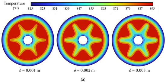
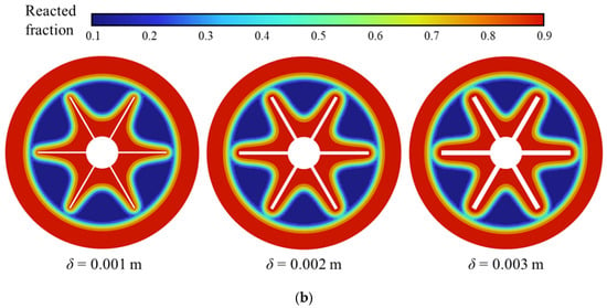
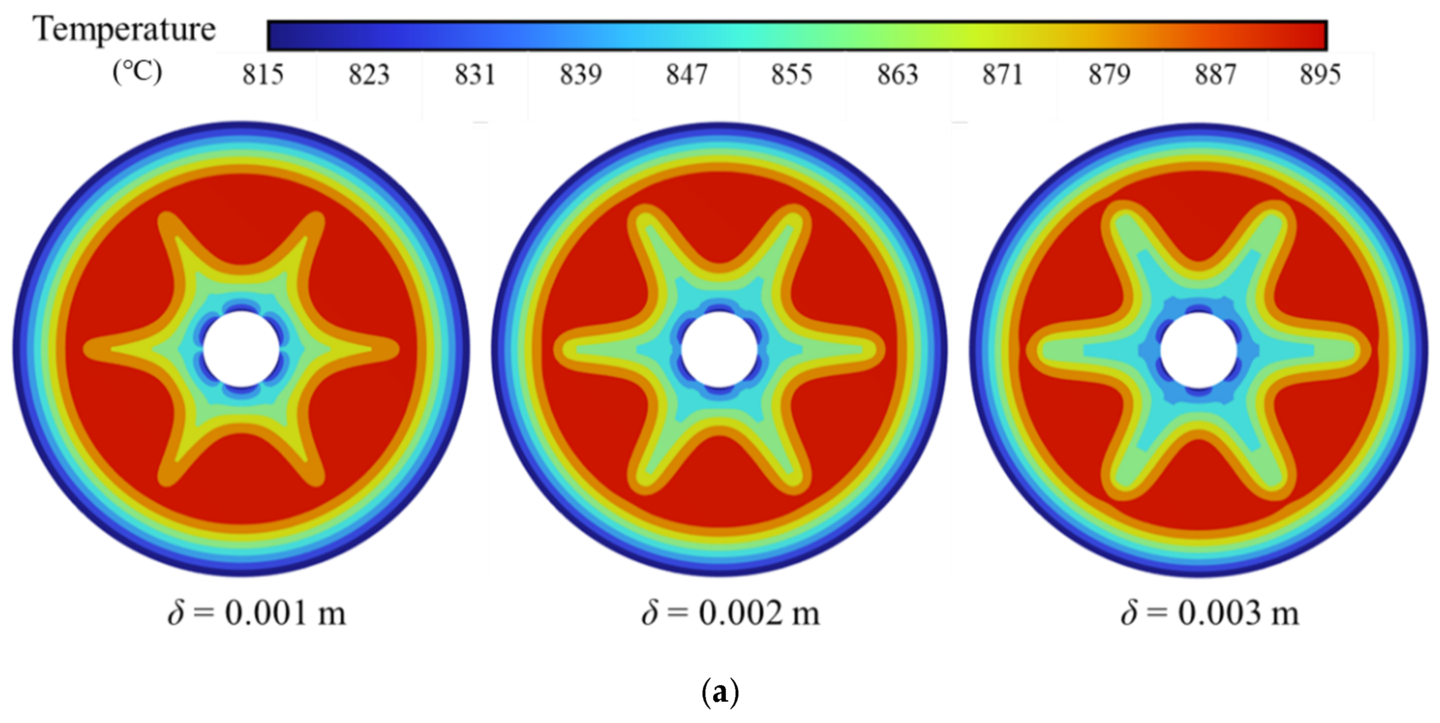
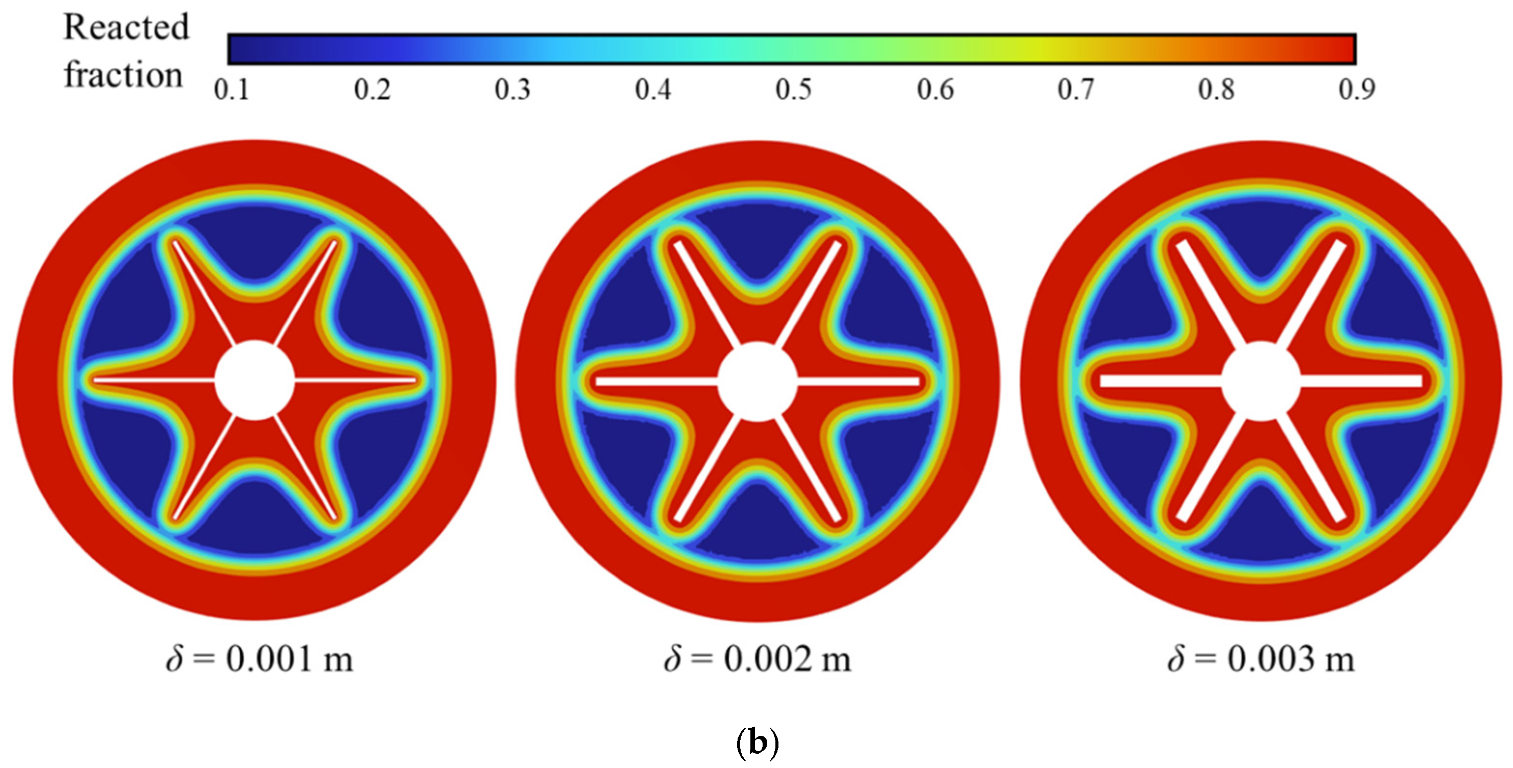
As shown in Figure 11b, increasing the fin thickness from 0.001 m to 0.002 m enhanced the reaction rate by 11.89%, whereas a further increase to 0.003 m resulted in a smaller improvement of 6.94%. Figure 12 presents the simulated conversion rate distributions at z = 0.05 m for different vertical fin thicknesses. This divergence can be attributed to the pronounced difference in the area of high-temperature, low-conversion regions between reactors with δ = 0.001 m and δ = 0.002 m at identical conversion levels, compared to the relatively similar areas observed between the δ = 0.002 m and δ = 0.003 m configurations. Consequently, increasing fin thickness from 0.001 m to 0.002 m leads to a more substantial acceleration of the reaction than increasing from 0.002 m to 0.003 m.
Figure 12.
Numerical simulation results at the z = 0.05 m cross-section under the same conversion rate for different fin thicknesses show the distributions of (a) temperature; (b) conversion rate.
3.2.3. Influence of Fin Length on Reactor Performance
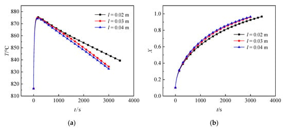
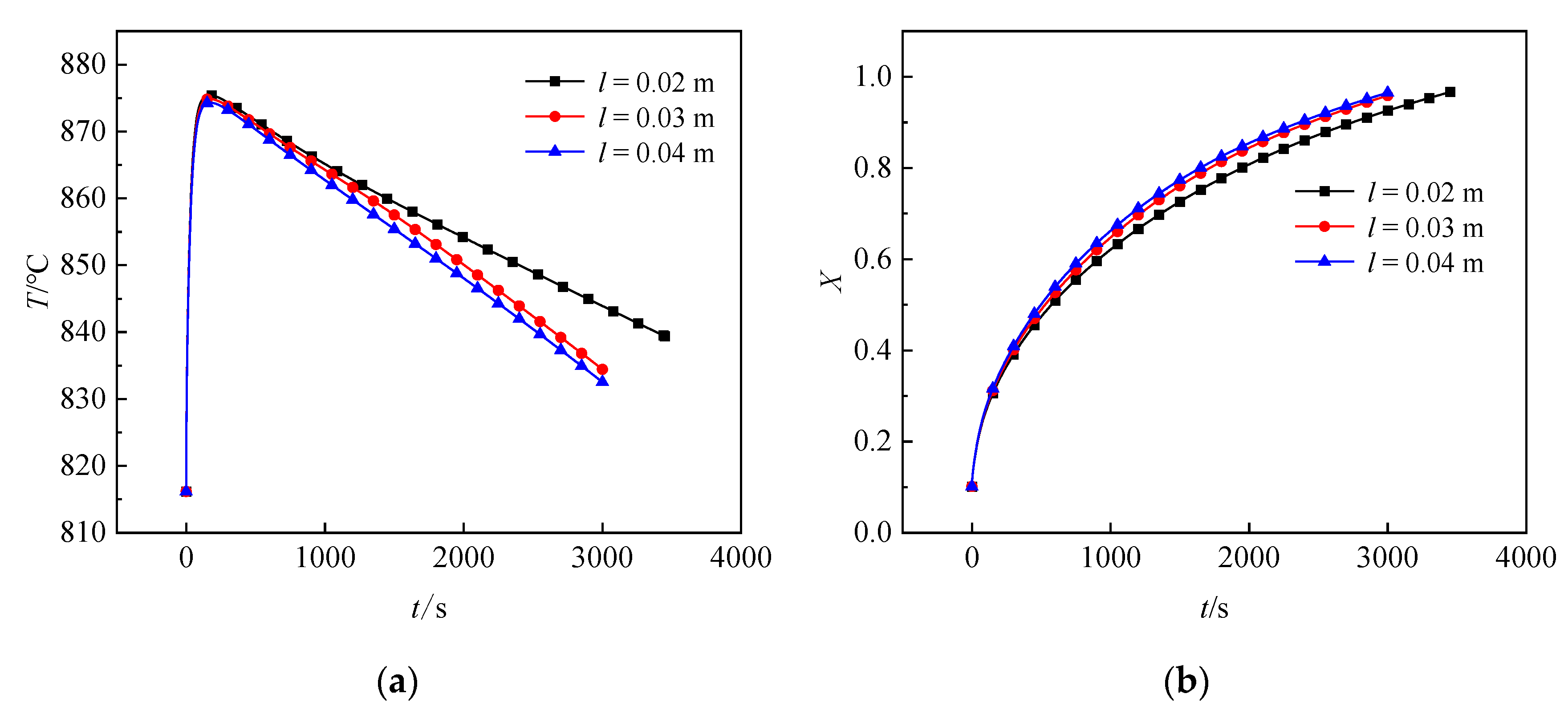
Based on the aforementioned research, this study examines the influence of vertical fin length on reactor performance under constant conditions including a fin thickness of 0.002 m and a fin count of six. Three fin lengths, specifically 0.02 m, 0.03 m, and 0.04 m, were compared to assess their effects on the carbonation process. Figure 13a presents the average temperature profiles under different fin lengths. The temperature rises rapidly upon reaction initiation, with only minor differences in peak temperatures across configurations. As the reaction proceeds, reactors with longer fins exhibit lower internal temperatures. Figure 13b displays the corresponding conversion rates, showing that longer fins lead to faster increases in conversion over time and higher final conversion levels. When the fin length was 0.02 m, the carbonation time was 3261 s. Increasing the length to 0.03 m reduced the carbonation time to 2910 s, corresponding to a 10.76% increase in reaction rate. A further increase to 0.04 m shortened the reaction time to 2839 s, with a 12.94% improvement in reaction rate. These results indicate that increasing vertical fin length can effectively reduce carbonation time and mitigate heat transfer limitations within the reactor.
Figure 13.
Effect of vertical fin length on (a) reactor temperature; (b) reactor conversion rate.
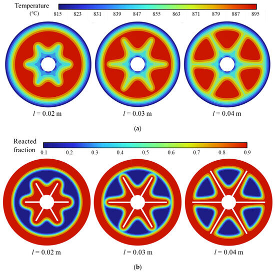
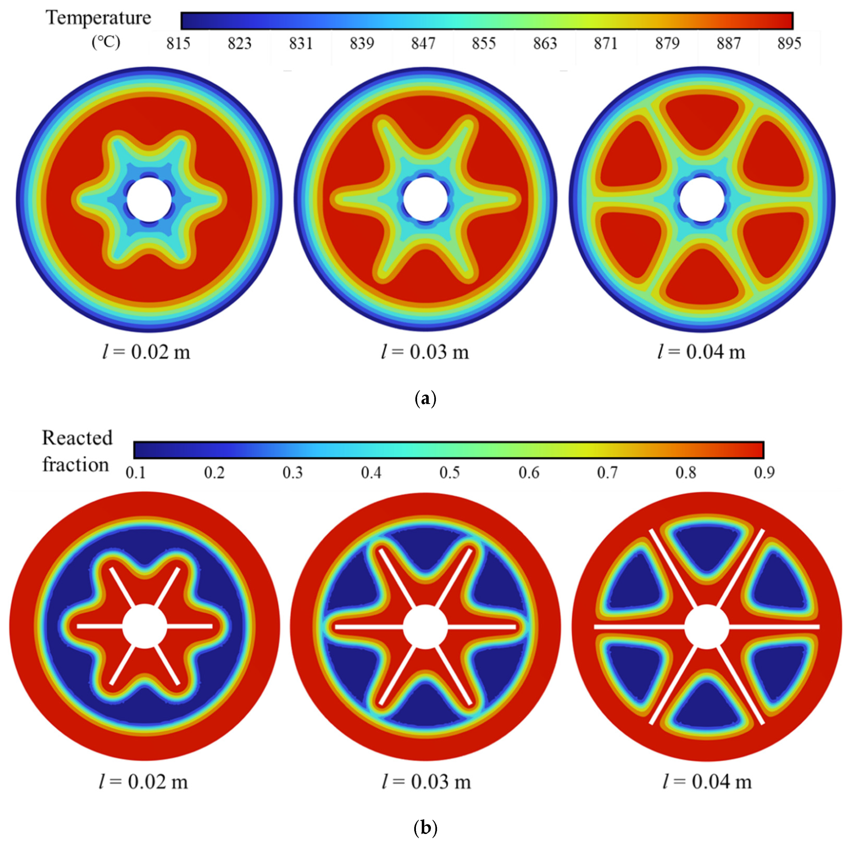
Numerical simulations of temperature and conversion rate at the z = 0.05 m cross-section under constant conversion rate conditions are presented in Figure 14. The results reveal significantly lower temperatures near the fins and outer wall than in other regions, which enhances local heat transfer and promotes the carbonation reaction. As a result, these areas exhibit notably higher conversion rates. A comparison of the temperature and conversion rate profiles shows minimal differences between fin lengths of 0.03 m and 0.04 m, whereas both differ substantially from the 0.02 m case. The conversion rate contour maps further support this observation: the low-conversion zones are nearly identical for fin lengths of 0.03 m and 0.04 m, indicating similar thermal and reactive performances. In contrast, the reactor with 0.02 m fins displays a distinctly larger low-conversion region, consistent with the observed differences in overall behavior.
Figure 14.
Numerical simulation results at the z = 0.05 m cross-section under the same conversion rate for different fin lengths show the distributions of (a) temperature; (b) conversion rate.
3.2.4. Influence of Fin Number on Reactor Performance
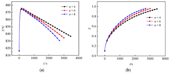
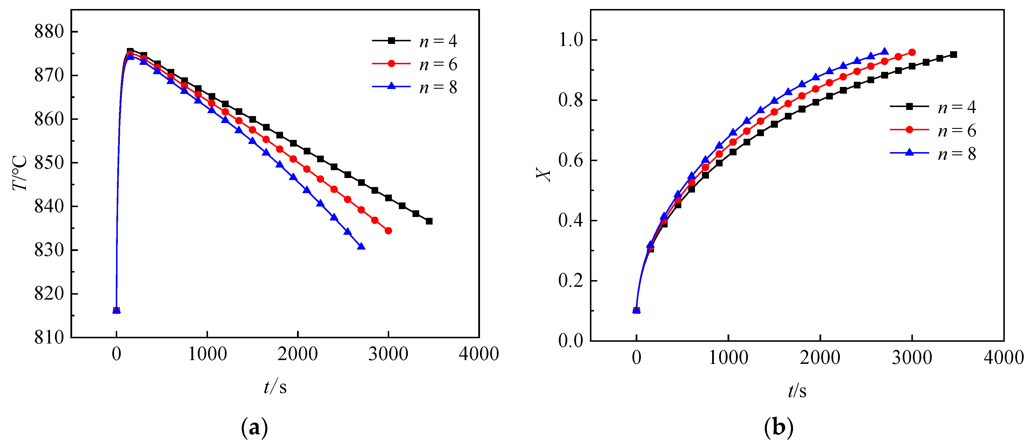
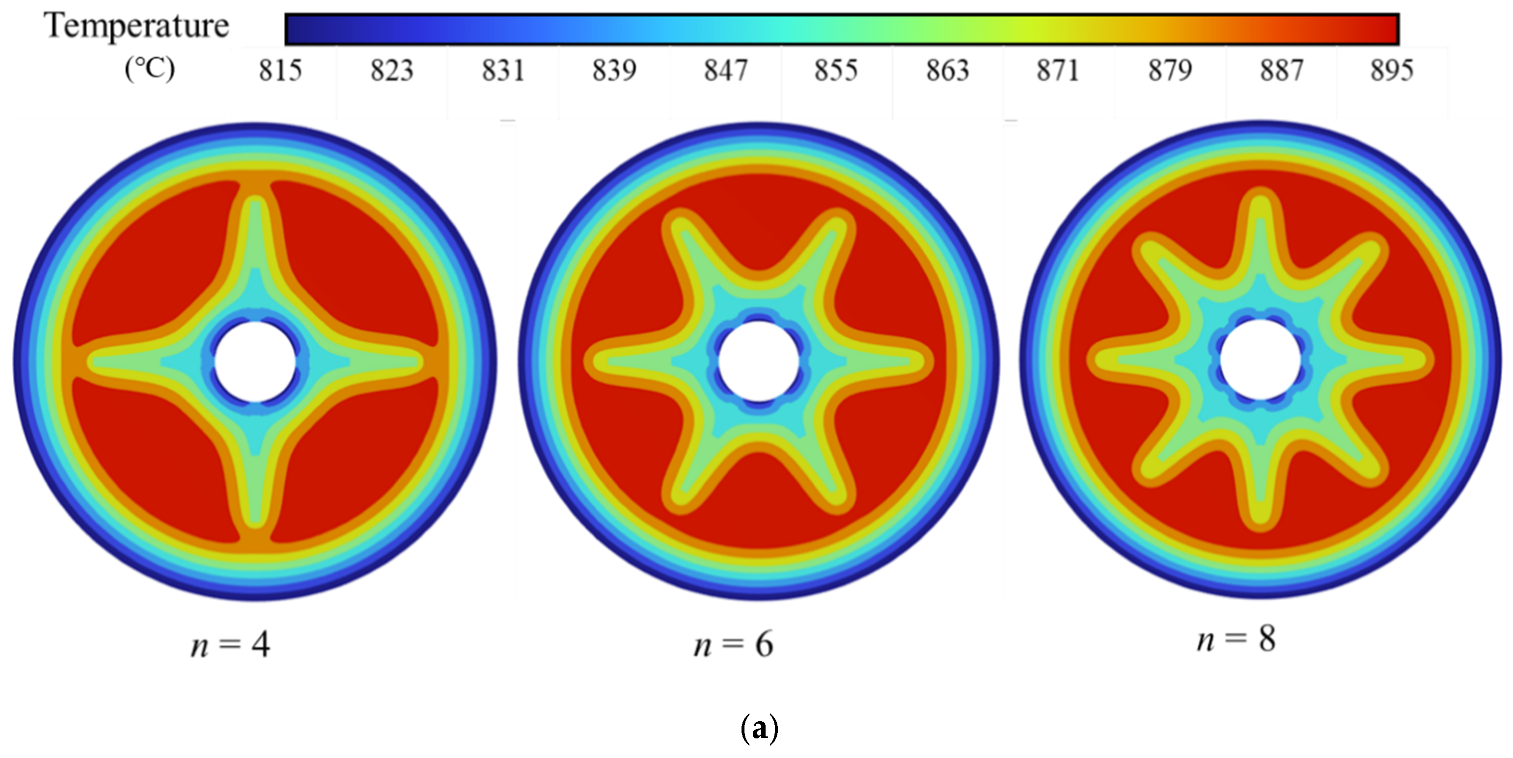
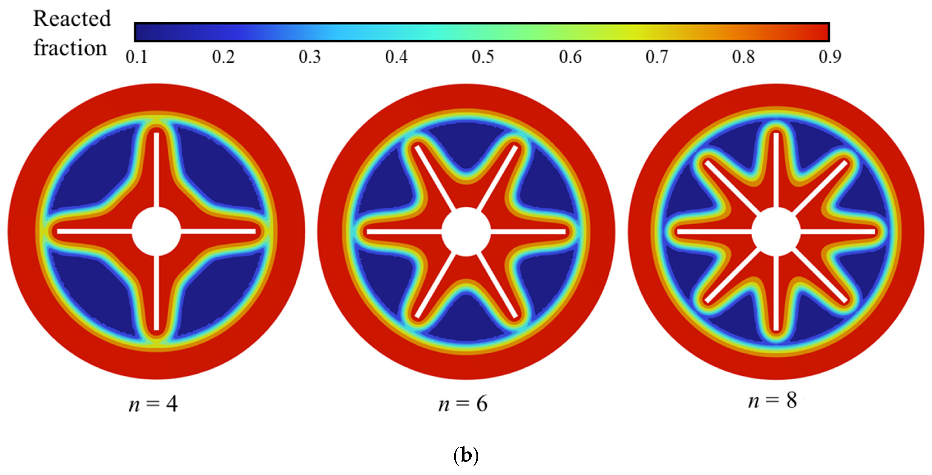
Based on the aforementioned research, this study investigates the influence of vertical fin quantity on reactor performance. Using constant fin dimensions of 0.002 m thickness and 0.03 m length, three configurations with four, six, and eight fins were compared to evaluate their effects on the carbonation process. Figure 15a presents the average temperature profiles for different fin quantities. The reactor temperature rises rapidly to its peak during the initial reaction stage, with fin number exhibiting negligible influence on the maximum temperature. As the reaction progresses, configurations with more fins demonstrate lower internal temperatures. Figure 15b shows the corresponding rates, indicating that higher fin numbers result in increased conversion rates throughout the reaction process. These phenomena are primarily attributed to enhanced heat conduction and improved heat dissipation capabilities with increasing fin numbers. The superior thermal performance promotes the carbonation reaction while maintaining lower operational temperatures. With four fins, the carbonation process requires 3434 s. Increasing to six fins reduces the reaction time to 2910 s, corresponding to a 15.26% increase in reaction rate. The configuration with eight fins further shortens the carbonation time to 2602 s, achieving a 24.23% improvement in reaction rate. These results demonstrate that increasing the number of vertical fins effectively enhances internal heat transfer and significantly reduces the carbonation duration.
Figure 15.
Effect of the number of vertical fins on (a) reactor temperature; (b) reactor conversion.
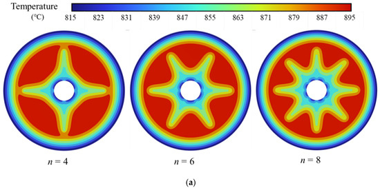
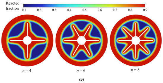
As shown in Figure 16, the simulated temperature and conversion rate distributions at z = 0.05 m under consistent conversion conditions reveal substantial variation in reactor performance with different fin numbers. Regions near the fins exhibit lower temperatures and higher conversion rates. Increasing the number of fins expands this influenced area, thereby reducing the extent of high-temperature, low-conversion zones and improving overall heat transfer efficiency. These observations align with the temperature and conversion rate trends presented earlier, confirming that greater numbers of vertical fins correspond to shorter carbonation times.
Figure 16.
Numerical simulation results at the z = 0.05 m cross-section under the same conversion rate for different numbers of fins show the distributions of (a) temperature; (b) conversion rate.
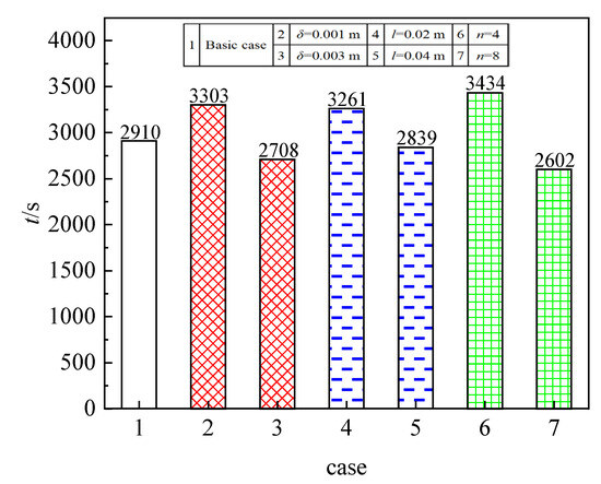
Figure 17 summarizes the effects of various vertical fin dimensions on the carbonation process within the reactor. The results clearly demonstrate that increases in fin thickness, length, and quantity improve heat dissipation, thereby addressing slow reaction rates associated with inadequate thermal management. For the basic case, the vertical fins had the following dimensions: a thickness of 0.002 m, a length of 0.03 m, and a number of six. Subsequent cases were developed by varying one of these parameters. Case 7, with a fin thickness of 0.002 m, length of 0.03 m, and eight fins, exhibited the shortest carbonation time. In contrast, Case 6, using the same thickness and length but only four fins, resulted in the longest duration.
Figure 17.
Effect of different-sized vertical fins on the carbonation process of a reactor.
Based on the present study, it is evident that incorporating fins markedly improves heat transfer within the reactor, shortening reaction time and increasing overall conversion efficiency. These findings align with several independent studies. For instance, Wang et al. [49] reported that in a Ca(OH)2/CaO-based thermochemical energy storage system, structural enhancements such as half-plate and tubular pin fin heat sinks significantly improved convective heat transfer and thermal performance. Similarly, Zhang et al. [50] highlighted that well-designed fins effectively enhance heat transfer in metal chloride–NH3 adsorption systems, which often have low thermal conductivity. Furthermore, Luo et al. [28] found that increasing the number of longitudinal fins reduces reaction time while influencing conversion, temperature, heat release rate, and effective heat transfer efficiency. Notably, during initial reaction stages, material near the fins exhibits a higher conversion rate due to their high thermal conductivity, a trend consistent with our observations.
4. Conclusions
This study focuses on the structural optimization of a thermochemical exothermic reactor based on CaCO3/CaO reactions. A fin-enhanced reactor model was developed by incorporating fins into a baseline reactor design with intermediate cooling channels. The effects of fin thickness, length, and number on reactor performance were systematically investigated. The main findings are summarized as follows:
- (1)
- The addition of fins significantly improves the poor heat transfer characteristics within the reactor, thereby reducing the reaction time and enhancing the overall conversion efficiency.
- (2)
- The incorporation of horizontal fins reduced the carbonation time by 584 s and increased the reaction rate by 11.81% compared to the reactor with cooling channels only. Increasing the thickness of the horizontal fins from 0.001 m to 0.003 m resulted in a reduction in carbonation time of 574 s and an increase in reaction rate of 13.16%. Increasing the length of the horizontal fins from 0.01 m to 0.03 m led to a reduction of 426 s in carbonation time and an improvement in reaction rate of 9.06%. Increasing the number of horizontal fins from four to eight reduced the carbonation time by 408 s and increased the reaction rate by 9.35%. The shortest carbonation time was achieved with a fin thickness of 0.003 m, length of 0.02 m, and number of four.
- (3)
- The use of vertical fins reduced the carbonation time by 2037 s and increased the reaction rate by 41.17% compared to the reactor equipped only with cooling channels. Increasing the thickness of the vertical fins from 0.001 m to 0.003 m shortened the carbonation time by 595 s and increased the reaction rate by 18.01%. Increasing the length of the vertical fins from 0.02 m to 0.04 m reduced the carbonation time by 422 s and improved the reaction rate by 12.94%. Increasing the number of vertical fins from four to eight decreased the carbonation time by 832 s and increased the reaction rate by 24.23%. The optimal configuration with the shortest carbonation time was achieved with a vertical fin thickness of 0.002 m, length of 0.03 m, and number of eight.
While our results show better performance for vertical fins, we acknowledge that the baseline horizontal and vertical cases did not use the same total fin material. In future studies, we will enforce a fair comparison by fixing the total fin mass/volume for both orientations and then varying orientation only. We will also control key geometric/thermal factors (e.g., fin thickness, fin number/spacing, and fin effective thermal conductivity) to isolate the influence of fin orientation on heat transfer, pressure drop, and conversion.
Author Contributions
Conceptualization, B.Y. and Y.D.; methodology, Y.D.; software, S.L.; validation, S.L., Z.Z. and Z.L.; formal analysis, S.L.; investigation, S.L. and Z.Z.; resources, W.Z.; data curation, Z.L.; writing—original draft preparation, S.L.; writing—review and editing, Y.D. and Z.L.; visualization, Z.Z.; supervision, B.Y.; project administration, W.Z.; funding acquisition, Y.D. All authors have read and agreed to the published version of the manuscript.
Funding
This work was supported by the National Key R&D Program of China (No. 2021YFF-0500401).
Data Availability Statement
The original contributions presented in this study are included in the article. Further inquiries can be directed to the corresponding author.
Conflicts of Interest
The authors declare no conflicts of interest.
Abbreviations
| Nomenclature | |
| A | Pre-exponential factor (s−1) |
| Cp | Heat capacity (J∙kg−1∙K−1) |
| dp | Solid particle size (μm) |
| Ea | Activation energy (kJ∙mol−1) |
| h | Height of reactor (mm) |
| ΔH | Enthalpy of reaction (kJ∙mol−1) |
| k | Kinetic coefficient |
| K | Permeability (m2) |
| M | Relative molecular mass |
| P | Pressure (Pa) |
| Qm | Mass source term (kg∙m−3∙s−1) |
| r | Width of reactor (mm) |
| R | Universal gas constant (J∙mol−1∙K−1) |
| ΔS | Reaction entropy (J∙mol−1∙K−1) |
| T | Temperature (K) |
| u | Velocity (m∙s−1) |
| wt | Maximum mass content of CO2 (%) |
| Greek letters | |
| ε | Porosity |
| λ | Thermal conductivity (W∙m−1∙K−1) |
| ρ | Density (kg∙m−3) |
| Subscripts | |
| bed | Reaction bed |
| eff | Effective |
| eq | Equilibrium |
| g | Gas |
| in | Inlet |
| out | Outlet |
| ref | Reference |
| s | Solid |
References
- Cormos, C.C. Solar-based calcium looping power plant with thermo-chemical energy storage capability: A techno-economic and environmental (LCA) analysis. Renew. Energy 2025, 251, 123431. [Google Scholar] [CrossRef] [Scilit]
- Alabi, T.M.; Agbajor, F.D.; Yang, Z.; Lu, L.; Ogungbile, A.J. Strategic potential of multi-energy system towards carbon neutrality: A forward-looking overview. Energy Built Environ. 2023, 4, 689–708. [Google Scholar] [CrossRef] [Scilit]
- Qiao, Y.; Sun, J.; Zhang, C.B.; Wei, J.J. Energy, exergy, economic and environmental (4E) analysis of a solar-coal hybrid system with calcium-looping thermochemical energy storage and carbon capture for power and methanol coproduction. Energy 2025, 334, 137563. [Google Scholar] [CrossRef] [Scilit]
- Wu, Z.F.; Li, X.T.; Wang, J.; Shi, Y.; Long, Y.; Ge, S.H.; Zhou, Z.J.; Sun, J. Impregnated layer solution combustion synthesis of dark Ca-based thermochemical energy storage composites for direct solar-driven calcium looping. Sep. Purif. Technol. 2025, 369, 133085. [Google Scholar] [CrossRef] [Scilit]
- Chai, F.Y.; Zhu, P.W.; Xu, H.R.; Xie, X.Y.; Xiao, G. Mn and Al co-modified CaO-based composites from various calcium precursors for thermochemical energy storage: High energy storage density and excellent solar absorption ability. Sol. Energy Mater. Sol. Cells 2024, 269, 112761. [Google Scholar] [CrossRef] [Scilit]
- Qays, M.O.; Ahmad, I.; Habibi, D.; Aziz, A.; Mahmoud, T. System strength shortfall challenges for renewable energy-based power systems: A review. Renew. Sustain. Energy Rev. 2023, 183, 113447. [Google Scholar] [CrossRef] [Scilit]
- Ekoue, M.K.; Woerman, M.; Clastres, C. Intermittency and uncertainty in wind and solar energy: Impacts on the French electricity market. Energy Econ. 2025, 142, 108176. [Google Scholar] [CrossRef] [Scilit]
- Jafarizadeh, H.; Soltani, M.; Alfraidi, W. A comprehensive Thermoeconomic assessment of liquid air and compressed air energy storage with solid/liquid/hybrid thermal energy storage (TES): Addressing air and TES material storage cost impacts. Appl. Energy 2025, 388, 125615. [Google Scholar] [CrossRef] [Scilit]
- Cao, C.; Ali, A.B.M.; Hussein, Z.A.; Singh, N.S.S.; Abdullaeva, B.; Zubair, A.; Salahshour, S.; Baghaei, S. Analysis of different phase change materials (PCMs) and wall material in a nano-circular space thermal energy storage (TES) system: A molecular dynamics approach. Int. J. Therm. Sci. 2025, 215, 109954. [Google Scholar] [CrossRef] [Scilit]
- Wang, K.; Yan, T.; Li, R.; Pan, W. A review for Ca(OH)2/CaO thermochemical energy storage systems. J. Energy Storage 2022, 50, 104612. [Google Scholar] [CrossRef] [Scilit]
- Xu, H.J.; Han, X.C.; Hua, W.S.; Friedrich, D.; Santori, G.; Bevan, E.; Vafai, K.; Wang, F.Q.; Zhang, X.L.; Yu, G.J.; et al. Progress on thermal storage technologies with high heat density in renewables and low carbon applications: Latent and thermochemical energy storage. Renew. Sustain. Energy Rev. 2025, 215, 115587. [Google Scholar] [CrossRef] [Scilit]
- Wang, Y.H.; Li, Y.; Xu, Z.Q.; Liu, S.L.; Shen, Y.L.; Ji, W.J.; Chen, T.S.; Li, Y.L.; Pulvirenti, B. Comprehensive evaluation of the photothermal conversion thermochemical energy storage composite materials: Material characterization, kinetics analysis and building heating application. Energy Build. 2025, 338, 115699. [Google Scholar] [CrossRef] [Scilit]
- Liu, X.; Yang, F.M.; Liu, X.; Wu, Y.P. A systematic evaluation of sorption-based thermochemical energy storage for building applications: Material development, reactor design, and system integration. Renew. Energy 2025, 245, 122831. [Google Scholar] [CrossRef] [Scilit]
- Obermeier, J.; Sakellariou, K.G.; Tsongidis, N.I.; Baciu, D.; Charalambopoulou, G.; Steriotis, T.; Müller, K.; Karagiannakis, G.; Konstandopoulos, A.G.; Stubos, A.; et al. Material development and assessment of an energy storage concept based on the CaO-looping process. Sol. Energy 2017, 150, 298–309. [Google Scholar] [CrossRef] [Scilit]
- Nie, F.L.; Ma, T.Z.; Zhang, Q.Q.; Chang, Z.S.; Ren, T.; Sayfieva, K.F.; Fu, M.K.; Li, X. Heat storage and release characteristics of a prototype CaCO3/CaO thermochemical energy storage system based on a novel fluidized bed solar reactor. J. Clean. Prod. 2024, 450, 142003. [Google Scholar] [CrossRef] [Scilit]
- Bailera, M.; Pascual, S.; Lisbona, P.; Romeo, L.M. Modelling calcium looping at industrial scale for energy storage in concentrating solar power plants. Energy 2021, 225, 120306. [Google Scholar] [CrossRef] [Scilit]
- Kumari, P.; Kaddah, F.; Al Amoodi, N.; AlHajaj, A.; Dumée, L.F. Enhanced CO2 capture via calcium looping with mesoporous ladle furnace stainless steel slag. Carbon Capture Sci. Technol. 2025, 14, 100354. [Google Scholar] [CrossRef] [Scilit]
- Zhang, H.J.; Xu, C.; Sun, X.Y.; Xu, B.W.; Liao, Z.R.; Liu, H.W. Study of co-promotion mechanism of Zr-Mn co-doped CaO-based composite for solar thermochemical energy storage. J. Energy Storage 2024, 97, 112877. [Google Scholar] [CrossRef] [Scilit]
- Feng, Q.N.; Wei, Y.; Fu, R.C.; Hu, Y.C. Preparation of dark Fe/Mn/Zr-doped CaO-based heat carriers for solar-driven thermochemical energy storage. Sol. Energy Mater. Sol. Cells 2025, 285, 113532. [Google Scholar] [CrossRef] [Scilit]
- Gao, C.Y.; Zhang, Y.; Liu, X.L.; Li, D. A Dual Modification Method to Prepare Carbide Slag into Highly Active CaO-Based Solar Energy Storage Materials. Ind. Eng. Chem. Res. 2023, 63, 769–779. [Google Scholar] [CrossRef] [Scilit]
- Chen, X.Y.; Gao, L.M.; Dong, Z.B.; Zhu, L.J. Different effects on thermal conductivity of Ca-based thermochemical energy storage materials for a concentrated solar power plant. Chem. Eng. Sci. 2023, 269, 118501. [Google Scholar] [CrossRef] [Scilit]
- Humbert, G.; Ding, Y.L.; Sciacovelli, A. Combined enhancement of thermal and chemical performance of closed thermochemical energy storage system by optimized tree-like heat exchanger structures. Appl. Energy 2022, 311, 118633. [Google Scholar] [CrossRef] [Scilit]
- Miao, Q.; Zhang, Y.L.; Jia, X.; Li, Z.B.; Tan, L.H.; Ding, Y.L. MgSO4-expanded graphite composites for mass and heat transfer enhancement of thermochemical energy storage. Sol. Energy 2021, 220, 432–439. [Google Scholar] [CrossRef] [Scilit]
- Zhao, Q.; Lin, J.Q.; Huang, H.T.; Xie, Z.W.; Xiao, Y.M. Papers Enhancement of heat and mass transfer of potassium carbonate-based thermochemical materials for thermal energy storage. J. Energy Storage 2022, 50, 104259. [Google Scholar] [CrossRef] [Scilit]
- Barrera, J.L.; Hartvigsen, J.J.; Hollist, M.; Pike, J.; Yarosh, A.; Fullilove, N.P.; Beck, V.A. Design optimization of integrated cooling inserts in modular Fischer-Tropsch reactors. Chem. Eng. Sci. 2023, 268, 118423. [Google Scholar] [CrossRef] [Scilit]
- Hawwash, A.A.; Hassan, H.; El Feky, K. Impact of reactor design on the thermal energy storage of thermochemical materials. Appl. Therm. Eng. 2020, 168, 114776. [Google Scholar] [CrossRef] [Scilit]
- Hosseini, M.J.; Ranjbar, A.A.; Rahimi, M.; Bahrampoury, R. Experimental and numerical evaluation of longitudinally finned latent heat thermal storage systems. Energy Build. 2015, 99, 263–272. [Google Scholar] [CrossRef] [Scilit]
- Luo, X.Y.; Li, W.; Zhang, L.J.; Zeng, M.; Klemes, J.J.; Wang, Q.W. Effects evaluation of Fin layouts and configurations on discharging performance of double-pipe thermochemical energy storage reactor. Energy 2023, 282, 128821. [Google Scholar] [CrossRef] [Scilit]
- Ranjha, Q.; Vahedi, N.; Oztekin, A. High-temperature thermochemical energy storage—Heat transfer enhancements within reaction bed. Appl. Therm. Eng. 2019, 163, 114407. [Google Scholar] [CrossRef] [Scilit]
- Ye, H.; Tao, Y.B. A novel three-dimensional cross-arranged fin structure for performance enhancement of thermochemical heat storage. J. Energy Storage 2023, 61, 106828. [Google Scholar] [CrossRef] [Scilit]
- Humbert, G.; Sciacovelli, A. Concurrent heat and mass transfer enhancement in thermochemical energy storage reactors via topology optimization. AI Therm. Fluids 2025, 2–3, 100013. [Google Scholar] [CrossRef] [Scilit]
- Pizzolato, A.; Sharma, A.; Maute, K.; Sciacovelli, A.; Verda, V. Design of effective fins for fast PCM melting and solidification in shell-and-tube latent heat thermal energy storage through topology optimization. Appl. Energy 2017, 208, 210–227. [Google Scholar] [CrossRef] [Scilit]
- Zhang, Y.; Liu, D.Y.; Ma, J.L.; Liang, C.; Chen, X.P. Improvement of heat transfer and reaction performance of a K2CO3 fixed-bed energy storage reactor using topology optimization. J. Energy Storage 2025, 111, 115443. [Google Scholar] [CrossRef] [Scilit]
- Chen, J.T.; Xia, B.Q.; Zhao, C.Y. Topology optimization for heat transfer enhancement in thermochemical heat storage. Int. J. Heat Mass Transf. 2020, 154, 119785. [Google Scholar] [CrossRef] [Scilit]
- Humbert, G.; Sciacovelli, A. Design of effective heat transfer structures for performance maximization of a closed thermochemical energy storage reactor through topology optimization. Appl. Therm. Eng. 2024, 239, 122146. [Google Scholar] [CrossRef] [Scilit]
- Ge, R.H.; Humbert, G.; Martinez, R.; Attallah, M.M.; Sciacovelli, A. Additive manufacturing of a topology-optimised multi-tube energy storage device: Experimental tests and numerical analysis. Appl. Therm. Eng. 2020, 180, 115878. [Google Scholar] [CrossRef] [Scilit]
- Shi, T.; Xu, H.J.; Qi, C.; Lei, B.; Wu, Y.T.; Zhao, C.Y. Multi-physics modeling of thermochemical heat storage with enhance heat transfer. Appl. Therm. Eng. 2021, 198, 117508. [Google Scholar] [CrossRef] [Scilit]
- Mathew, A.; Nadim, N.; Chandratilleke, T.T.; Paskevicius, M.; Humphries, T.D.; Buckley, C.E. Kinetic investigation and numerical modelling of CaCO3/Al2O3 reactor for high-temperature thermal energy storage application. Sol. Energy 2022, 241, 262–274. [Google Scholar] [CrossRef] [Scilit]
- Han, X.J.; Liu, S.L.; Zeng, C.; Yang, L.; Shukla, A.; Shen, Y.L. Investigating the performance enhancement of copper fins on trapezoidal thermochemical reactor. Renew. Energy 2020, 150, 1037–1046. [Google Scholar] [CrossRef] [Scilit]
- Liu, H.Z.; Wang, W.T.; Zhang, Y.N. Performance gap between thermochemical energy storage systems based on salt hydrates and materials. J. Clean. Prod. 2021, 313, 127908. [Google Scholar] [CrossRef] [Scilit]
- Moulakhnif, K.; Ousaleh, H.A.; Sair, S.; Bouhaj, Y.; El Majd, A.; Ghazoui, M.; Faik, A.; El Bouari, A. Renewable approaches to building heat: Exploring cutting-edge innovations in thermochemical energy storage for building heating. Energy Build. 2024, 318, 114421. [Google Scholar] [CrossRef] [Scilit]
- Jia, Y.; Wang, Y.F.; Zhou, X.Z.; Xu, Y.J.; Liu, M.; Ling, H.S.; Chen, H.S. Critical review of CaO/Ca(OH)2 thermochemical energy storage material. Renew. Sustain. Energy Rev. 2025, 216, 115678. [Google Scholar] [CrossRef] [Scilit]
- Ghafurian, M.M.; Elmegaard, B.; Weinberger, P.; Arabkoohsar, A. Salt hydrates in renewable energy systems: A thorough review. Energy 2024, 313, 133808. [Google Scholar] [CrossRef] [Scilit]
- Deng, Y.J.; Zhu, Z.Y.; Liu, Z.M.; Li, W.; Zhang, W.; Yu, B. Study on coupling characteristics of thermal-fluid-chemical multi-physics field in CaCO3/CaO thermochemical exothermic reactor. Chem. Eng. Sci. 2024, 299, 120453. [Google Scholar] [CrossRef] [Scilit]
- Huang, C.F.; Xu, M.; Huai, X.L. Experimental investigation on thermodynamic and kinetic of calcium hydroxide dehydration with hexagonal boron nitride doping for thermochemical energy storage. Chem. Eng. Sci. 2019, 206, 518–526. [Google Scholar] [CrossRef] [Scilit]
- Yong, Z.; Mata, V.; Rodrigues, A.E. Adsorption of carbon dioxide at high temperature—A review. Sep. Purif. Technol. 2002, 26, 195–205. [Google Scholar] [CrossRef] [Scilit]
- Moller, K.T.; Ibrahim, A.; Buckley, C.E.; Paskevicius, M. Inexpensive thermochemical energy storage utilising additive enhanced limestone. J. Mater. Chem. A 2020, 8, 9646–9653. [Google Scholar] [CrossRef] [Scilit]
- Che, J.B.; Wang, F.N.; Song, C.; Wang, R.; Li, Y.S. Modeling of energy carrier in solar-driven calcium-looping for thermochemical energy storage: Heat-mass transfer, chemical reaction and stress response. Chem. Eng. J. 2023, 463, 142435. [Google Scholar] [CrossRef] [Scilit]
- Wang, B.Y.; Wang, Z.Y.; Ma, Y.; Liang, Y.J. Heat Transfer Enhancement of Indirect Heat Transfer Reactors for Ca(OH)2/CaO Thermochemical Energy Storage System. Processes 2021, 9, 1136. [Google Scholar] [CrossRef] [Scilit]
- Zhang, W.Y.; Ji, Y.; Fan, Y.; Mehari, A.; Gao, N.; Zhang, X.; Jiang, L. Three-dimensional numerical study on finned reactor configurations for ammonia thermochemical sorption energy storage. Chem. Eng. Sci. 2024, 300, 120599. [Google Scholar] [CrossRef] [Scilit]

Disclaimer/Publisher’s Note: The statements, opinions and data contained in all publications are solely those of the individual author(s) and contributor(s) and not of MDPI and/or the editor(s). MDPI and/or the editor(s) disclaim responsibility for any injury to people or property resulting from any ideas, methods, instructions or products referred to in the content. |
© 2026 by the authors. Licensee MDPI, Basel, Switzerland. This article is an open access article distributed under the terms and conditions of the Creative Commons Attribution (CC BY) license.