


Abstract
The increasing demand for high-power electric vehicle charging systems with Vehicle-to-Grid (V2G) capability highlights the need for modular, scalable power converters. This paper proposes a hierarchical control strategy for a high-power, multi-port electric vehicle charging station. The system, based on a Series-Parallel Modular Multilevel Converter (SP-MMC) with isolated modules, is managed by a coordinated control strategy that integrates proportional-integral-resonant regulators, nearest-level control with voltage sorting, and single-phase-shifted modulation. The proposed system enables simultaneous, independent regulation of multiple bidirectional, isolated direct current ports while maintaining grid-side power quality and internal variables of the SP-MMC. The proposed control is validated using real-time Model-In-the-Loop (MIL) simulations that include sequential port activation, bidirectional power flow, and charging operation. MIL results demonstrate stable operation with controlled DC-link voltage ripple, accurate per-port current tracking, and near-unity grid power factor under multi-port operation.
1. Introduction
The global transition to electromobility is a key element in decarbonization efforts worldwide. This transition has been highlighted by the rapid increase in sales of electric vehicles (EVs), which reached 40 million units by 2023 [1]. As a result, there is a growing need for a reliable charging network that can provide high power quickly and efficiently. Fast charging is essential for the widespread adoption of EVs, as it helps alleviate consumer concerns about long charging times and range anxiety. Moreover, as battery technology continues to advance and average capacities are expected to reach 100 kWh by 2030, the demand for fast and ultra-fast charging infrastructure will continue to rise.
Conventional fast chargers typically rely on multi-stage architectures, such as an Active Front End rectifier followed by an isolated Direct Current (DC) to DC converter [2]. While effective, these designs can be complex and face limitations in modularity and scalability. As an alternative, Modular Multilevel Converters (MMCs) have emerged as a relatively new technology for high-power EV charging applications.
Modular Multilevel Converters (MMCs), originally developed for high-voltage direct current (HVDC) transmission [3,4], have recently been adapted for medium-voltage and high-power applications. Novel topologies, such as the Modular Multilevel Matrix Converter [5] and the Hexverter [6], demonstrate the versatility of the MMC concept for various applications [7,8]. MMCs are well recognized for their inherent fault tolerance and robust fault-ride-through capability. MMC clusters are composed of series-connected half-bridge or full-bridge submodules, which provide distributed energy storage through the Cluster Capacitor Voltage (CCV). The CCVs are defined as the sum of the individual capacitor voltages within a cluster and allow for the converter to accommodate unbalanced operating conditions and transient overvoltages [5,9].
Furthermore, in the event of a submodule or semiconductor failure, the affected unit can be bypassed, allowing for the converter to continue operating with reduced capacity but without loss of functionality [10]. As a result, MMCs have consistently demonstrated strong ride-through performance under grid faults, maintaining controllability and operational continuity during voltage sags and asymmetric fault conditions [11].
In the context of electromobility, recent studies have explored MMCs due to their inherent modularity, scalability, high efficiency, and superior output power quality, making them promising candidates for next-generation charging infrastructure [12]. Nevertheless, existing MMC-based multi-port charger designs often face limitations regarding the number of independently controlled charging outputs [13]. Most implementations use the power cells to provide galvanic isolation, which can cause power imbalance and restrict the number of unidirectional charging ports [14].
The initial concept of the Series-Parallel Modular Multilevel Converter (SP-MMC) was introduced as a multi-port architecture [15]. Early implementations used a single High-Frequency (HF) transformer to couple the parallel stages. This single-transformer arrangement restricts scalability and limits independent port regulation due to inherent magnetic coupling. In addition, all charging ports remain magnetically coupled, preventing independent regulation and fault isolation.
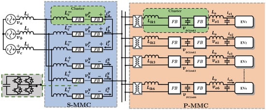
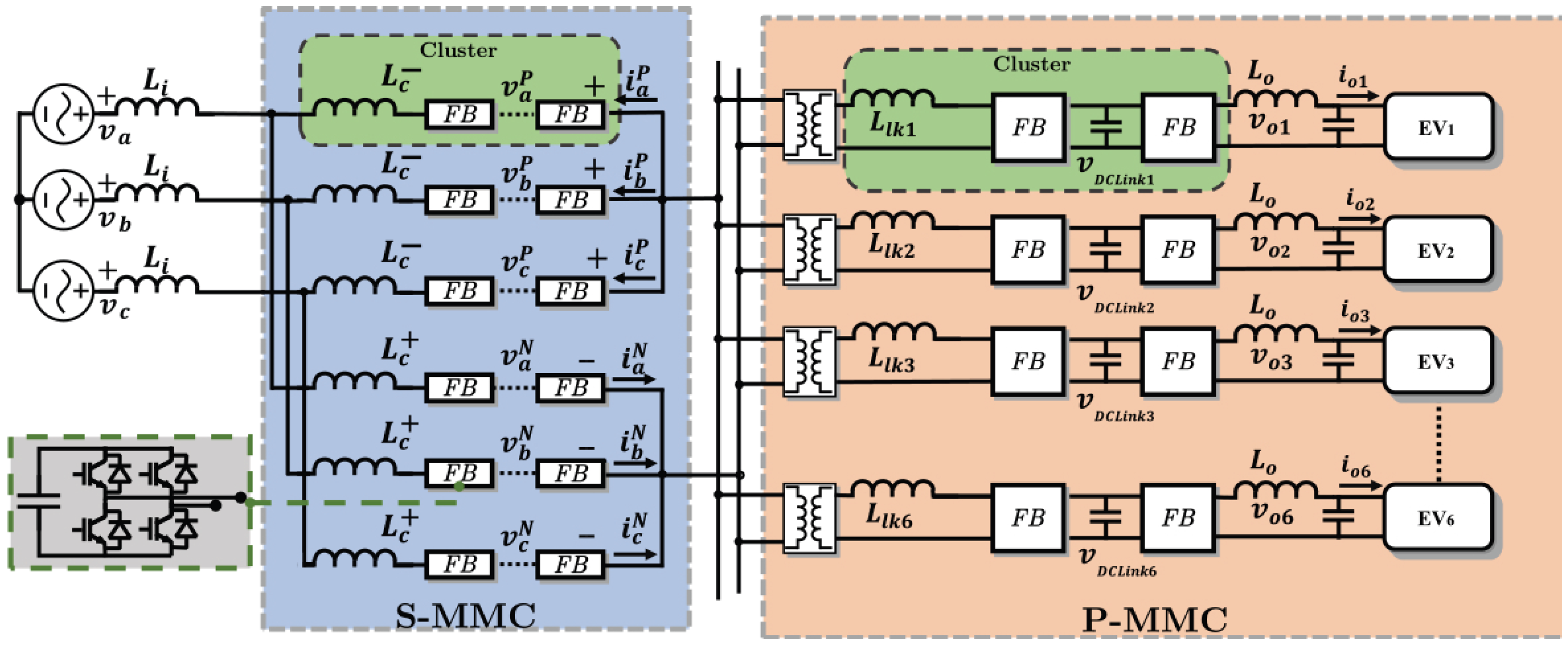
The topology presented in this paper resolves this constraint by adopting a modular DC-DC stage with per-port isolation. As shown in Figure 1, the SP-MMC is composed of a Series-MMC, a DC link, and parallel DC modules. Every parallel module features an HF transformer and a Back-to-Back (B2B) Full-Bridge (FB) cell, offering galvanic isolation to enable multi-port scalability.
Figure 1.
SP-MMC topology.
The architecture presented in this work is a variation of a Solid-State Transformer (SST), a core technology enabling isolated medium-voltage charging. To situate this contribution, it is necessary to compare it with recent SST topologies. Several existing designs concentrate on optimizing individual components, such as the magnetic elements or overall efficiency, or are limited to single-port operation. Architectures based on multi-winding high-frequency transformers introduce control complexity and increased fault propagation. Designs using per-cell Dual Active Bridges (DABs) face challenges related to balancing and modularity.
This work adopts a different approach based on port-level modularity using per-port HF-isolated DAB stages. Recent developments, such as the modular DAB converter in [16], achieve module-level high-voltage isolation and scale charging power by replicating single-output DC–DC modules. In contrast, the proposed SP-MMC targets a scalable multi-port architecture capable of simultaneously regulating multiple HF-isolated, bidirectional ports (demonstrated with six ports) by extending the parallel stage with additional isolated modules. To make this distinction explicit in terms of port scalability and the associated coordination/communication requirements, Table 1 provides a unified comparison of representative isolated charger or SST converter families.
Table 1.
Benchmarking of SST converters.
Conversely, this paper proposes a hierarchical control strategy for the SP-MMC multi-port charger. The approach follows the general structure of classical multi-loop control. However, the resulting control problem differs from a standard power–voltage (e.g., ) implementation. Instead, multiple HF-isolated bidirectional ports must be coordinated while enforcing capacitor-energy balancing in the SP-MMC under time-varying and asymmetric port demands. This requirement motivates the need for an explicit coordination layer. This layer dispatches port setpoints subject to shared energy balancing constraints, improves port-to-port decoupling, and enables selective port blocking while preserving the operation of the remaining ports under time-varying and asymmetric port demands. This introduces an explicit coordination layer that dispatches port setpoints under shared balancing constraints, thereby strengthening port-to-port decoupling and enabling selective port blocking while maintaining the operation of the remaining ports.
The proposed system is validated using a Model-in-the-Loop (MIL) simulation executed in real time. The MIL setup includes the power stage, the control architecture, and a battery model. The converter is implemented as a 42-cell SP-MMC, composed of a 30-cell Series-MMC connected to the grid and a 12-cell Parallel-MMC stage supplying six isolated and independently regulated DC outputs. The simulation is executed using a PLECS RT Box 3 platform. Each output port is connected to a virtual battery bank model that emulates EV packs with different voltage levels. Simulation results confirm stable operation under bidirectional power flow and validate the proposed architecture for multi-port fast charging applications.
The main contributions of this work are as follows:
- A hierarchical control strategy is developed that combines PI and PR controllers, SPS modulation for DAB regulation, NLC with voltage sorting for capacitor voltage balancing in the S-MMC, and the systems-level integration for six simultaneous, bidirectional ports.
- Demonstration of simultaneous, decoupled control of six ports under dynamic charging and V2G scenarios using a real-time MIL simulation of a 42-cell SP-MMC with six independently controlled DC ports.
The structure of this paper is as follows. Section 2 details the proposed converter topology and its mathematical modeling. Section 3 describes the hierarchical control strategy for the series and parallel stages. Section 4 presents the MIL simulation results and performance evaluation. Section 5 summarizes the main conclusions of the study.
2. Proposed SP-MMC
Figure 1 shows the proposed EV charger based on the SP-MMC. This converter is composed of two stages: the Series-MMC (S-MMC) and the Parallel-MMC (P-MMC). On the one hand, the S-MMC consists of six clusters that connect the three phases of the electrical network to a high-frequency transformer. Each cluster comprises a series connection of an inductor and FB power cells. The S-MMC generates low-voltage (LV) and HF outputs, connected to the parallel HF transformers. On the other hand, the P-MMC offers multiple DC charging ports by connecting B2B-FB cells. The first FB converts the Alternating Current (AC) signal from HF to DC by regulating the voltage of the floating capacitor, whereas the second FB regulates the output current. As a result, the floating capacitor in each P-MMC cluster has some degree of freedom, enabling it to adapt to various voltage levels.
2.1. S-MMC Modeling
MMCs are usually represented by voltage-current and voltage-power models. The work by [22,23] presents an overview of the modeling strategies used in AC-AC MMC. Consequently, the following subsections present the model applied to the S-MMC, based on [24,25], and using the transformation to decouple the electrical variables of the input, output, and S-MMC. This transformation is constructed from orthogonal vectors, which guarantees the decoupling between the sum () and difference () subspaces. As a result, the dynamics related to capacitor-energy balancing and those associated with grid-side power exchange can be treated separately.
2.1.1. S-MMC Voltage-Current Model
Each cluster of the S-MMC can be considered a controlled voltage source; thus, the following expression is derived:
The dynamics of the input and output ports are decoupled by applying to (1). The transform is used to transform a generic matrix into a decoupled matrix as follows:
where the transforms and are defined below:
2.1.2. S-MMC Voltage-Power Model
The voltage in each capacitor is floating, and their regulation is the main control challenge in MMCs. Usually, a voltage-energy and voltage-power relationship is derived to regulate the CCVs. For a generic cluster , the following relationships are given by
where and are the energy and CCV in the cluster , is the average voltage in the cluster. Additionally, the CCV is calculated as for a cluster with n cells. Applying this voltage–power relationship to the six clusters yields
The elements of are calculated by multiplying the voltage and current of each cluster (e.g., ), and represents the CCV. As proposed in [25], the is applied to (9) to obtain a decoupled representation of the average and ripple components of the CCVs:
The relation of (10) represents the Power-CCV model of the S-MMC in coordinates. The voltage terms of the left side of (10) have the following physical meaning and control modes:
- The voltage terms , ,, and represent CCV imbalances in the clusters and can be controlled using negative sequence of the input frequency in and .
- The voltage terms represents CCV imbalances in the clusters and can be controlled using positive sequence of the input frequency in .
- The voltage terms represents the average voltage of the CCV and can be controlled using positive sequence of the input frequency in .
Furthermore, the circulating current can be manipulated to control the total capacitor voltages in the coordinates.
2.2. P-MMC Modeling
The P-MMC consists of parallel-connected B2B FB modules. Each module operates as an independent, isolated charging port, converting the high-frequency AC voltage from the S-MMC link into a regulated DC output acting like a power transfer stage operating in HF.
2.2.1. HF Power Transfer Model
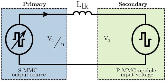
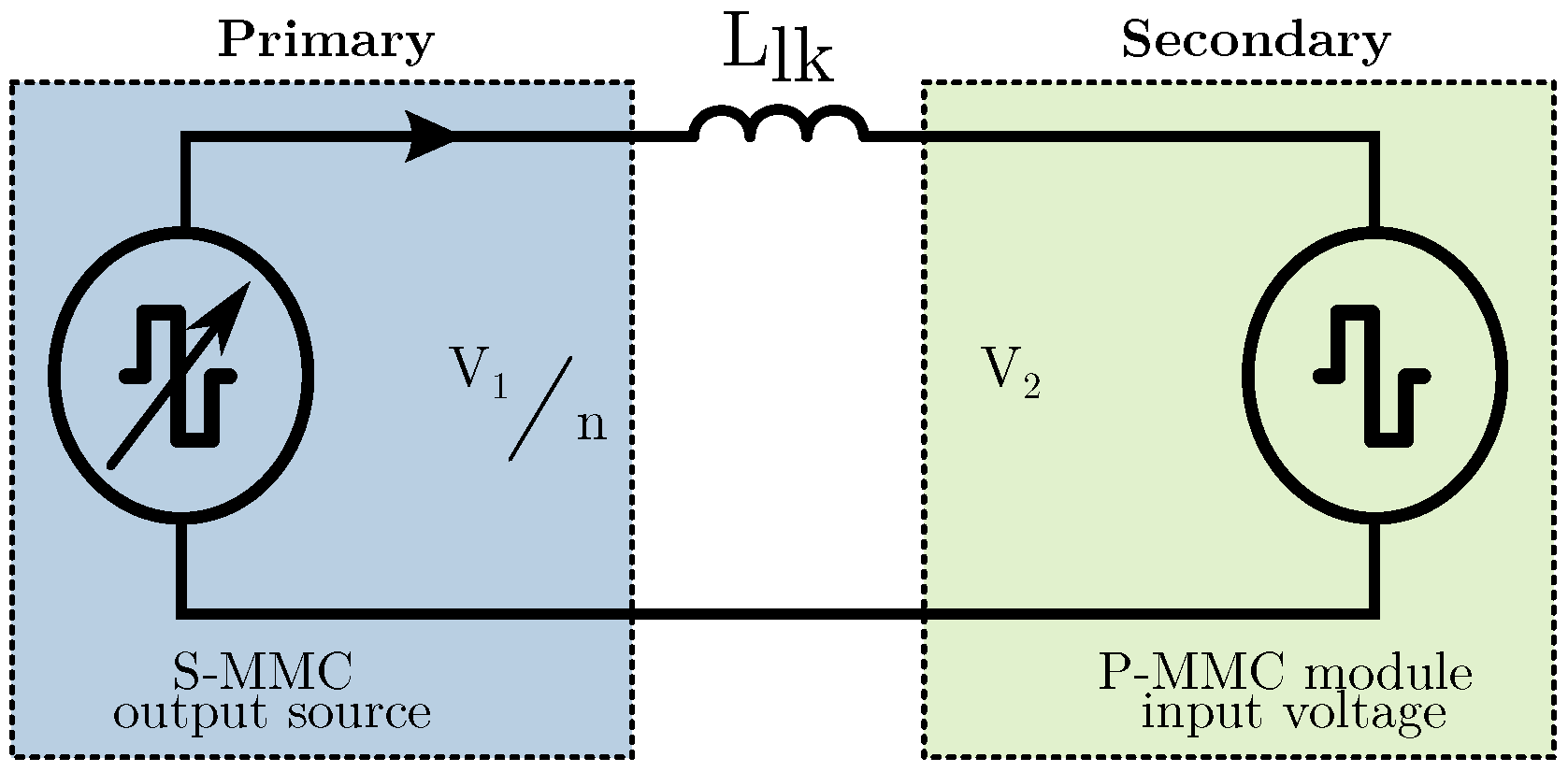
The mechanism for power transfer relies on the phase-shift principle typical of a DAB [26,27]. Essentially, power flow can be likened to the exchange between two voltage sources linked by a choke [28], and it is influenced by the phase angle () between these two voltages, as illustrated in Figure 2. Hence, bidirectional (V2G) operation can be controlled if one voltage source is out of phase with the other, as the power flow depends on both the sign and magnitude of the phase angle [29,30].
Figure 2.
Equivalent circuit model for AC-DC power transference.
The S-MMC generates a high-frequency square wave voltage at the primary of the HF transformer, while the P-MMC synthesizes a phase-shifted square wave at the secondary. The phase-shift between the primary and secondary defines the current through the leakage inductance ():
Using:
where and are the primary and secondary voltages, and are the duty cycles of each FB, is the phase-shift between both FBs, and is the switching frequency in .
Then, the average HF power can be defined as follows:
The higher-order harmonics in (16) can be neglected, as indicated in [31,32], and the power is simplified to
Equation (17) is a control-oriented simplification of (16) that adopts the fundamental approximation under an operating envelope with bounded phase shift and duty ratios close to 0.5, where the fundamental term dominates.
Magnetic components are a critical part of HF-link converters and impose practical constraints on performance and operating range, for instance, leakage dispersion, ZVS boundaries, core saturation, and thermal limits. These non-idealities can reduce the admissible phase-shift range and introduce gain variations in the HF power stage, affecting HF-link power dynamics and, consequently, DC-link regulation.
In this work, the MIL model assumes ideal magnetic components in order to isolate and validate the proposed control architecture and system-level integration. Accordingly, the leakage inductance is selected to provide a sufficiently wide operating margin so that the DAB power-transfer capability does not limit the control study [30]. Although practical hardware implementation activities would necessitate a dedicated stage for magnetics co-design and optimization, like in [27], these hardware-focused design tasks lie beyond the scope of this paper.
2.2.2. FB-Buck Model
3. Proposed Control Strategy
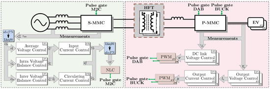
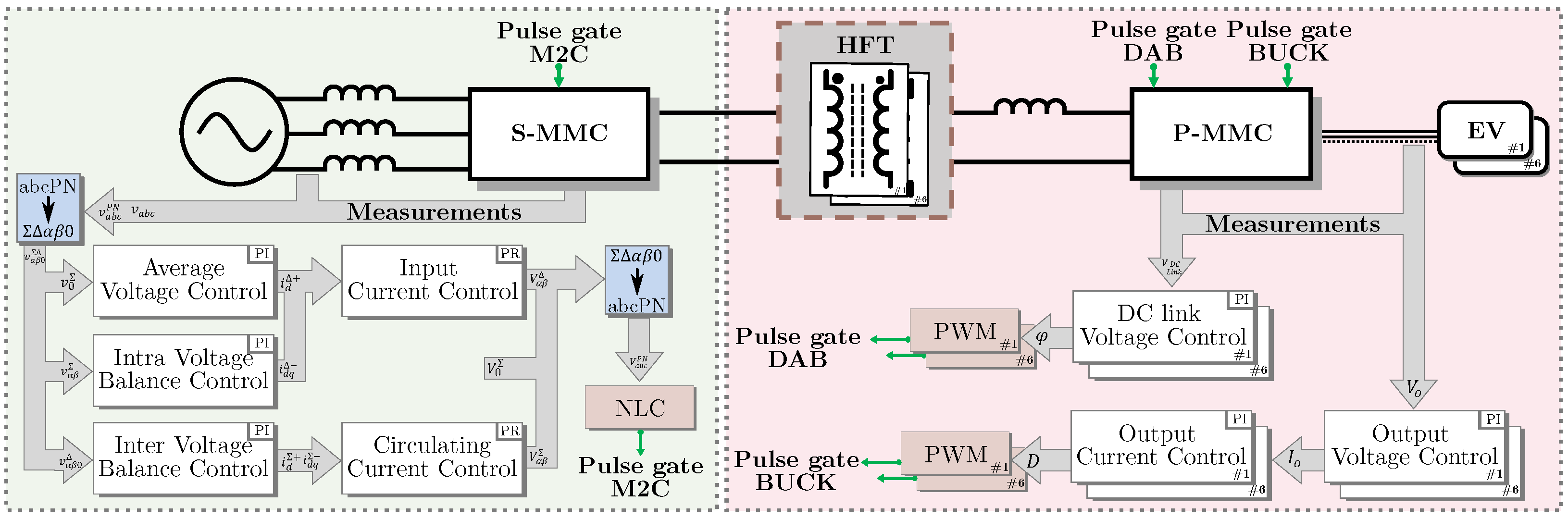
The proposed control strategy for the SP-MMC coordinates the operation of the S-MMC and P-MMC stages to achieve the following key objectives: (i) regulation and balancing of the cluster capacitor voltages in the S-MMC, (ii) control of the high-frequency link voltage to manage power transfer between stages, and (iii) independent regulation of the output voltages and currents for multi-port EV battery charging [33]. Figure 3 presents an overview of the proposed control architecture, which is organized into three subsystems:
Figure 3.
Control strategy for the SP-MMC system.
- S-MMC voltage–current control: Responsible for regulating the output voltage applied to the transformer primary and balancing the capacitor voltages of each cluster [34,35].
- HF power transfer control: Regulates power exchange between the S-MMC and the P-MMC by adjusting the phase shift between the primary and secondary voltages of the transformer [36,37,38].
- P-MMC voltage–current control: Manages the DC-link capacitor voltages and regulates the output voltage and current of each load port.
In addition to these control loops, specific modulation strategies are implemented at each stage. The S-MMC employs NLC, selected for its suitability for high-frequency synthesis without requiring high switching rates [39]. The P-MMC employs Pulse Width Modulation (PWM) as a simple and effective method to regulate the constant DC output [40].
3.1. S-MMC Voltage–Current Control
The S-MMC control loop (left side in Figure 3) regulates the AC output voltage and balances the capacitor voltages in each cluster with a decoupled frame like [9]. First, the transform is applied to the voltages and currents of the cluster. Then, the derivative of the voltages in (10) is calculated using notch filters to obtain the average value of the total voltages of the cluster. The reference value for these components is obtained using the transformation, as described in (2), so the average value of the CCV is controlled with and the other terms control the balance, which, in steady-state, keeps the balance operation of the S-MMC, represented as follows:
A PI controller on the average voltage defines the references for the circulating and input currents in coordinates. PR controllers in the frame then shape these currents to produce the desired cluster voltage references, as shown in Figure 3 and used in [3,41]. The term is generated as a high-frequency square wave, while avoids zero-sequence injection. Finally, the inverse transform and NLC modulation synthesize each switching signal.
In practice, capacitor tolerances, precharge conditions, and load variations cause an initial spread of capacitor voltages and yield nonzero imbalance components around the mean operating point in (20). These deviations are regarded as disturbances and are compensated by the balancing control (using measured capacitor voltages, NLC voltage sorting, and outer average-energy/voltage control), following standard MMC formulations [9]. To further improve robustness against abrupt disturbances, sliding-mode approaches have been proposed as a promising enhancement [42].
3.2. P-MMC DC-Link Voltage Control
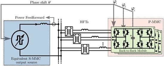
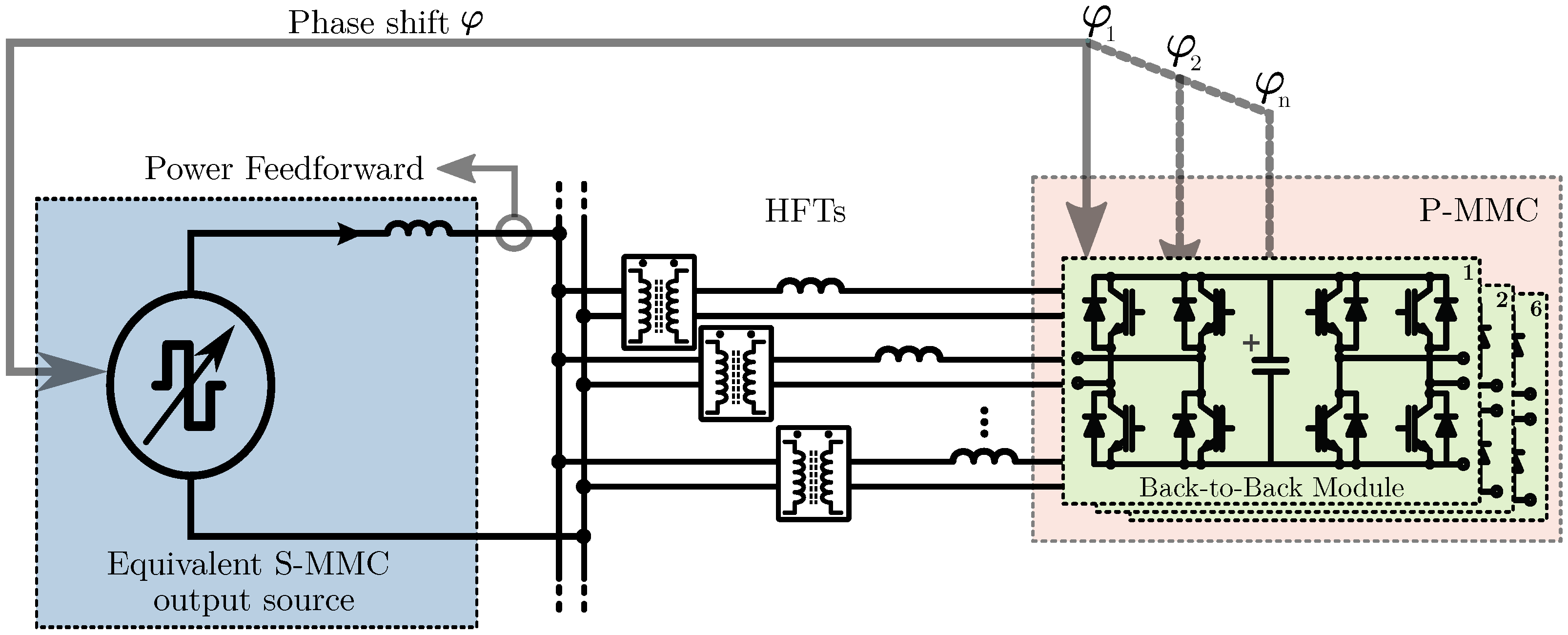
The HF link control, shown in Figure 4, uses the S-MMC square-wave output to feed a high-frequency transformer (right side in Figure 3). Power flow between series and parallel stages is adjusted using an SPS method: a PI controller on the parallel-stage DC-link voltage computes the phase shift between the primary and secondary waveforms. Changing alters the real power transferred, enabling tight DC-Link regulation during charging/discharging.
Figure 4.
Secondary HF phase shift control of parallel modules with equivalent S-MMC output voltage.
In the parallel stage, FB power cells regulate the DC-Link voltage of each converter. As shown in the right side of Figure 3, PI controllers compare each with its reference and generate the phase angle for each module in the SP-MMC link, like in Figure 4 [43]. The resulting voltage references for each FB are synthesized using PWM.
Finally, the P-MMC output stage regulates the DC load ports. A hierarchical PI structure is used: the outer loop controls each output voltage and sets the reference current; the inner loop regulates the output current. Both loops run in coordinates, with voltage references transformed back to for PWM. This ensures stable voltage and current at each DC port under varying load profiles.
By defining the operational parameters and constraining the operating margin, a first-order plant can be achieved without linearizing the previously derived expressions. This strategy allows for more flexible control variables while ensuring accurate reference tracking for each output module. When the system is operated within acceptable limits, precise overall system tracking can be maintained with zero steady-state error. Conversely, surpassing these limits results in increased control challenges and a loss of dynamics.
3.3. P-MMC Output Voltage Control
The nested voltage-current control loop that regulates the DC point of the system with the load parameters is controlled by a buck interleaved topology [40,44]. This FB cell allows for the current stress in each leg to be split, thereby decreasing current ripple [45]. In this way, the point of load is stabilized, enabling bidirectional charging and tracking of load voltage and current depending on the I–V curve required for the charging/discharging.
3.4. Modulation Strategies
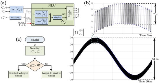
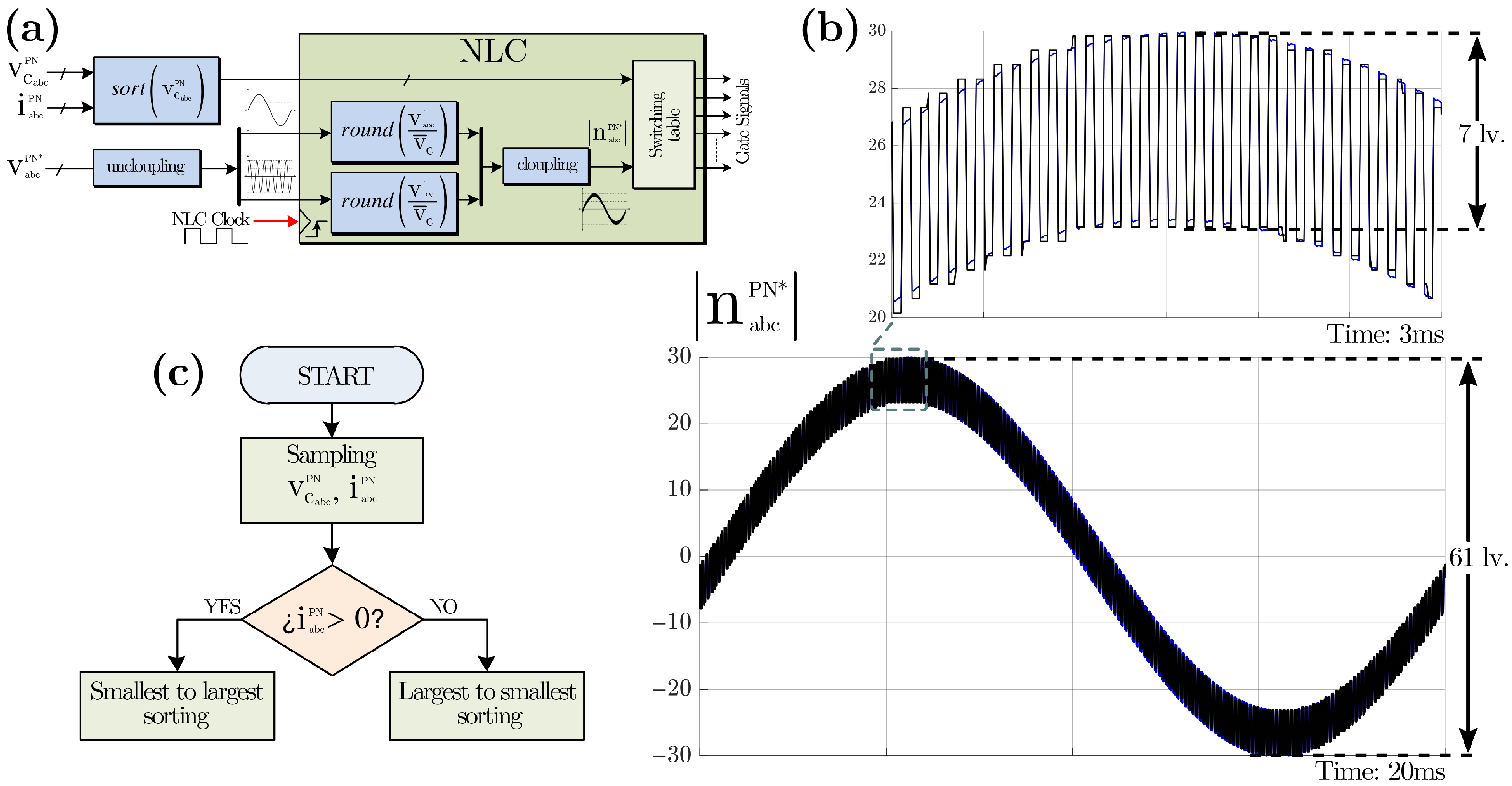
The S-MMC employs an NLC strategy to synthesize the reference voltage waveforms. NLC is a modulation method that does not rely on a carrier signal. Instead, it directly selects the closest voltage level that a cluster can synthesize from its available discrete voltage states. This approach results in lower switching frequency and reduced switching losses compared to carrier-based PWM techniques. As shown in Figure 5a, the NLC algorithm determines the output voltage as
where is the instantaneous reference voltage, is the average voltage of the cluster capacitors, and the round() function selects the nearest integer level. Given that each cluster consists of various FB cells, the number of available levels is 2n + 1. , when decoupled into its low- and high-frequency terms, allows for greater correlation for the NLC algorithm.
Figure 5.
Modulation scheme. (a) NLC Algorithm. (b) Rounded levels synthesized. (c) Bubble sorting.
A key advantage of NLC is its simplicity and scalability; however, voltage resolution and spectral quality depend on the number of levels. In the proposed system, S-MMC clusters synthesize multilevel voltages that combine a low-frequency component (for grid interaction) and a high-frequency square wave component (to drive the primary transformer), as illustrated in Figure 5b.
To mitigate capacitor voltage imbalance across power cells, the NLC algorithm integrates a cell-sorting strategy based on instantaneous capacitor voltage measurements and the direction of cluster current. Cells with higher voltages are selected when the current direction favors discharge, and vice versa. This method ensures capacitor voltage balancing over time without the need for dedicated circulating current controllers. Figure 5c illustrates the sorting process used for cell selection.
The P-MMC uses PWM-based modulation techniques for its DAB input and interleaved buck output. On the one hand, the phase shift control between the primary and secondary voltages is modulated at 10 kHz to generate the HF signal of the S-MMC. On the other hand, the modulation of the interleaved modules is performed at 40 kHz each, reducing the ripple of the controlled signals for constant voltage and/or current operation by half, depending on the load curve.
3.5. Control Loops Bandwidth Design
A critical aspect of a proposed control system is ensuring stability and preventing undesirable coupling between the multiple nested and parallel control loops. This is achieved by applying a standard bandwidth separation principle. While a detailed gain-tuning analysis is beyond the scope of this paper, the design hierarchy is detailed as follows:
- S-MMC voltage current control: The outer capacitor voltage balancing (Section 3.1), including average, inter, and intra balancing regulation, are tuned to 5 Hz. The inner control loops, including PR regulators, for input–output and circulating currents are designed at 200 Hz. Finally, the NLC and sorting are implemented with an equivalent switching frequency of 10 kHz.
- A frequency of 10 kHz is used in the HF link. The output control regulates the voltage transformer using a bandwidth of 30 Hz.
- P-MMC voltage–current control: The voltage loop provides the reference for the inner current loop and is designed to be slower, using 10 Hz. Additionally, the inner current control is the fastest loop, designed with 200 Hz to quickly track the current reference from the outer voltage loop.
The proposed hierarchy follows a time-scale separation principle to maintain the dynamics decoupled, enabling each nested control loop to be independently regulated without affecting one another. The capacitor-energy dynamics are slow and are therefore regulated with 5–10 Hz bandwidths to avoid interaction with the grid frequency. On the one hand, current controllers are designed at 200 Hz to ensure tracking and decoupling. On the other hand, the HF-link phase-shift control is slower than the switching frequency, but faster than the outer DC-port voltage loops. Finally, the discrete real-time implementation imposes sampling-related limits that prevent overly aggressive tuning. This selection minimizes cross-coupling among nested loops and preserves stability margins under multi-port operation.
4. MIL Results
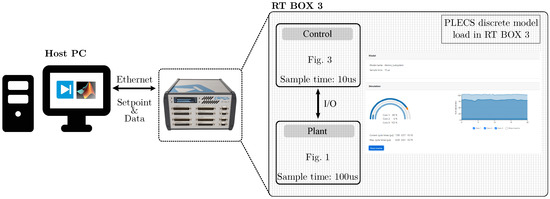
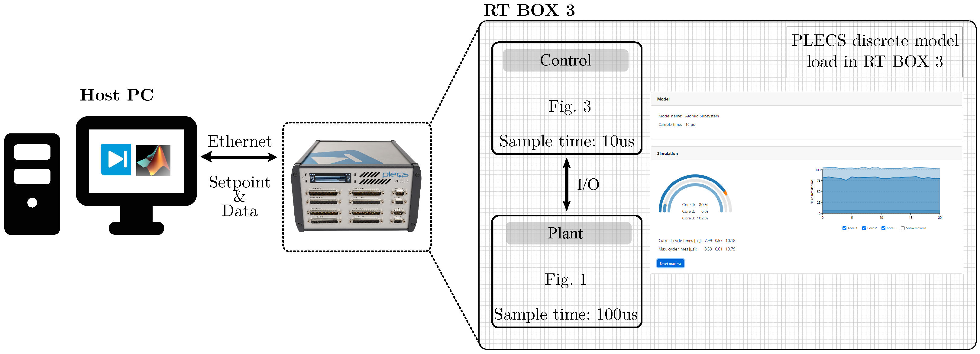
This section presents the results obtained using a MIL real-time simulation of a SP-MMC charger with six independent DC charging ports. The MIL real-time simulation is implemented on an RT Box 3 platform, as shown in Figure 6.
Figure 6.
MIL-based implementation of the SP-MMC.
The electrical plant and the control algorithms are executed on the same PLECS RT Box 3 platform. The plant is simulated using a fixed-step solver with a time step of 10 μs, and the control algorithms are executed with 100 μs for control, ensuring real-time execution. The S-MMC is composed of 60 cells with a voltage rating of 1500 V, while the P-MMC includes 12 cells to facilitate 6 DC charging ports. The proposed charger is designed to function with an input grid of 13.2 kV at 50 Hz. The HF link is regulated to 3.3 kV and 10 kHz, while the DC outputs are controlled at 825 V. The main electrical parameters of the MIL simulation are outlined in Table 2.
Table 2.
MIL real-time simulation main parameters.
This implementation is developed taking into account the challenges of the control platforms used in this work, such as those indicated in [46].
Three tests are introduced to confirm the correct operation of the SP-MMC and its control strategy: the operation of the S-MMC, the operation of the HF power transfer link, and a dynamic operation test involving multi-port charging and discharging.
4.1. MIL Limitations and Validation Scope
In the MIL framework, magnetic components such as transformers and inductors are represented as ideal linear elements. As a result, hardware-level physical phenomena—including core saturation, hysteresis effects, high-frequency core and eddy-current losses, thermal behavior, and parasitic inter-winding capacitances—are not captured. Consequently, the scope of this validation is limited to the evaluation of control performance, transient stability, and coordinated operation of the hierarchical control system, rather than detailed hardware or magnetic design verification.
The electrical plant and control algorithms are executed in real time on the RT Box 3 platform. The power stage is simulated using a fixed-step solver with a time step of 10μs, selected to accurately represent the HF-link dynamics while ensuring real-time execution. The control tasks are implemented discretely with a sampling period of 100 μs, consistent with the targeted control bandwidths and the computational capabilities of the RT Box 3.
Due to the discrete-time implementation, the MIL results inherently include sampling and computational delays associated with digital control execution. These delays are considered in the tuning of the hierarchical control loops, whose bandwidths are deliberately selected to remain below the Nyquist frequency imposed by the control sampling rate. While switching-level dead-times and detailed PWM delays are not explicitly modeled, the proposed MIL framework provides a realistic assessment of the control-integration behavior at system level.
4.2. Test 1: S-MMC Operation
The S-MMC links the AC grid to the HF port, which operates at 3.3 kV and 10 kHz. The main control objective is the regulation of the floating capacitor voltages in each cell. The converter comprises ten cells per cluster (sixty in total), the capacitor dynamics can be represented by the six CCVs as shown in (9), and the average voltage of the entire converter as indicated in (10), which is denoted by .
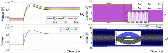
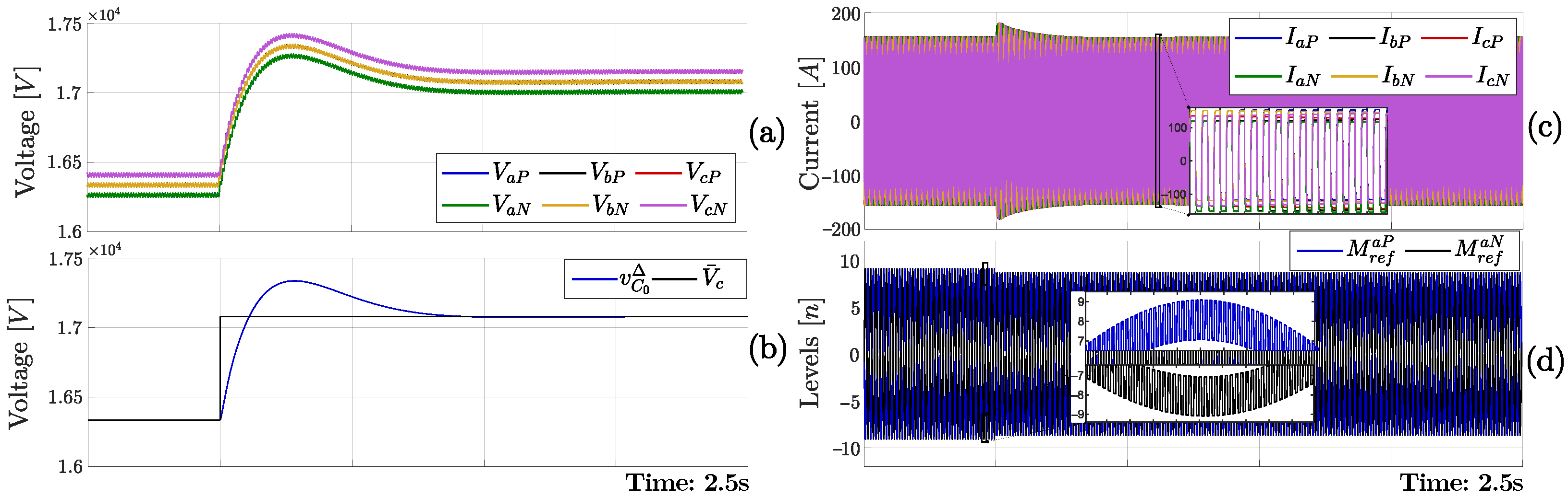
Figure 7a shows the evolution of the six CCVs during a step change in the reference voltage. All CCVs exhibit a coordinated transient, reaching the new operating point with low ripple. The peak-to-peak ripple remains well regulated in a band, with less than 100 V of ripple. The reference tracking of is illustrated in Figure 7b. The average voltage follows the reference step with a damped transient, with a setting time of 500 ms, an overshoot less than 2%. This coordinated response validates the ability of the controller to maintain the average converter voltage.
Figure 7.
S-MMC balance variables: (a) CCVs. (b) Average voltage reference tracking. (c) Cluster Currents. (d) Voltage reference for a positive and negative cluster cells.
The cluster currents are presented in Figure 7c. As expected, the S-MMC produces square-wave HF currents imposed by the DAB-based energy transfer mechanism. The current waveforms remain phase-aligned with the HF port voltage to ensure efficient power transfer. The zoomed-in view highlights the symmetry and periodicity of the HF current.
Finally, Figure 7d shows the modulation levels generated by the top and bottom clusters of the S-MMC leg. Both signals display sinusoidal envelopes that are shifted in phase by 180°, along with the high-frequency switching components needed to produce the HF square-wave output. Since the two cluster voltages are in contraphase, their difference yields a clean HF square voltage at the port.
4.3. Test 2: Bidirectional HF Power Transfer Control
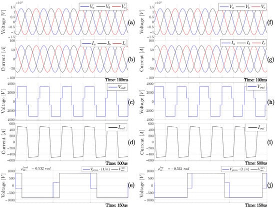
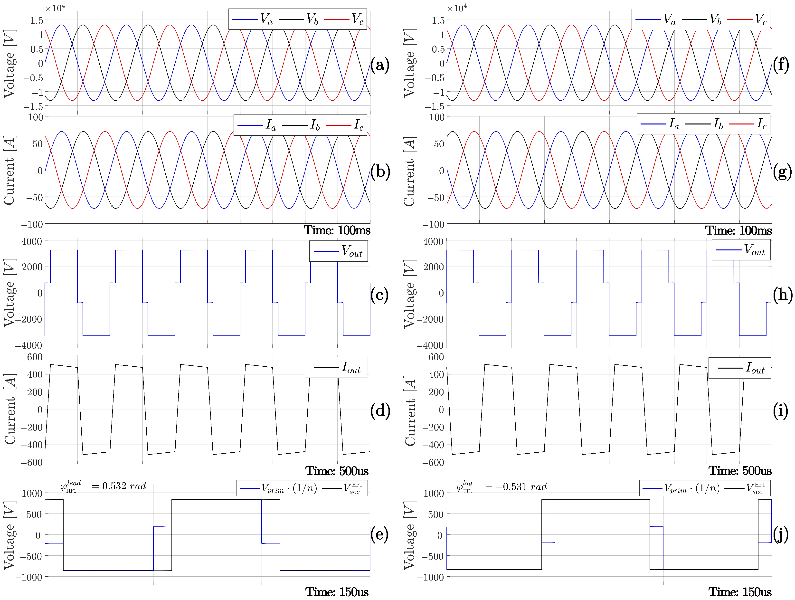
The first 100 ms shown in Figure 8a,b correspond to the steady-state operation of the system at rated power. The three-phase input voltages and currents remain balanced and sinusoidal during steady-state charging operation. The grid currents are in phase with the voltages, indicating unity power factor operation.
Figure 8.
SP-MMC results of charging (a) input port AC voltages, (b) input port AC currents, (c) HF Voltage, (d) HF current, (e) lead modulation reference with SPS for V2G power flow, and discharging (f) input port AC voltages, (g) input port AC currents, (h) HF Voltage, (i) HF current, (j) lag modulation reference with SPS for discharging power flow.
Figure 8c,d show a time-expanded view of the HF waveforms. The HF voltage exhibits a square-wave pattern from the S-MMC NLC sequence, and the HF current follows the trapezoidal waveform.
According to (17), the power transfer can be controlled by the phase shift between the input and output of the HF transformer. Figure 8e illustrates the phase shift, denoted as , between the input and output of the HF transformer for a single parallel DC port, first in charging with positive .
For V2G mode, the first 100 ms shown in Figure 8f,g corresponds to the steady-state operation of the system at rated inverse power. The three-phase input voltages and currents remain balanced and sinusoidal during steady-state charging operation. The grid currents are in antiphase with the voltages, indicating unity power factor operation for power injection to grid.
Similarly, Figure 8h,i shows the square-wave voltage in antiphase with the current, demonstrating the reverse flow defined by the negative , with energy from the batteries in the DC ports injected into the three-phase network. During this interval, the grid current leads the voltage, indicating reverse active power transfer.
Figure 8j illustrate the negative phase shift, between the input and output of the HF transformer for a single parallel DC port operating on V2G mode.
4.4. Test 3: Multiple Charging and V2G Functionality
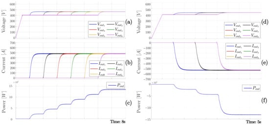
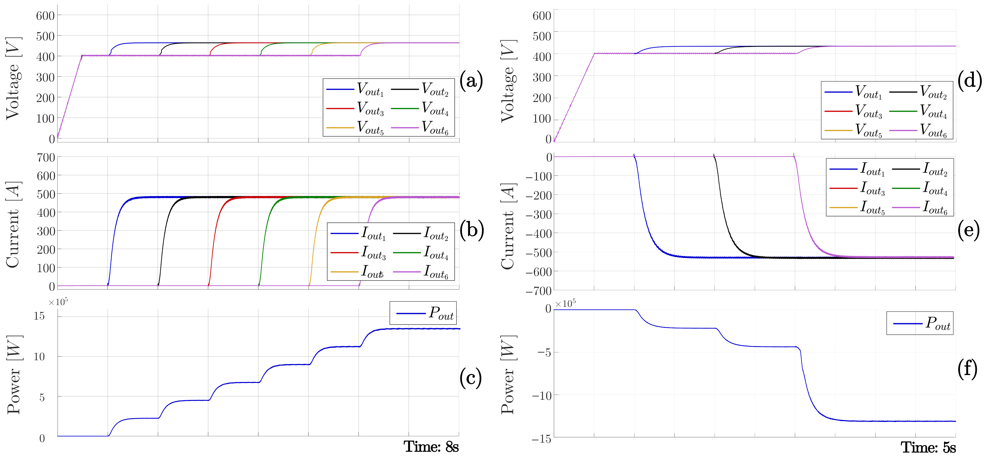
Figure 9 summarizes the behavior of the SP-MMC outputs during a multi-port charging sequence followed by a V2G multi-port discharging sequence operation. The test evaluates the capability of the control system to regulate six independent DC charging ports.
Figure 9.
(a) DC charging port voltages. (b) DC charging port currents. (c) Output charging power. (d) DC V2G port voltages. (e) DC V2G port currents. (f) Output V2G power.
4.4.1. Charging Mode
The staircase power profile at the DC-side in Figure 9a reflects the sequential activation of the six DC ports, demonstrating the ability to operate with asymmetric loads, since as long as there is no power flow in a port, it remains preloaded without affecting system operation. Each port is regulated in voltage mode, considering 450 V vehicle batteries, increasing from an initial precharge level of 400 V to a charging target of 469 V. Then, the current is sequentially regulated to 479 A, as shown in Figure 9b. Each DC charging port is controlled to deliver ≈ 225 kW and is activated sequentially prior to its initial preload state, taking approximately 250 ms to stabilize to 90% of its nominal value. The SP-MMC operates under a progressive load until it reaches 1.350 MW, as shown in Figure 9c. Initially, is positive; therefore, six load steps of 225 kW are applied, as shown in Figure 9a,b, to the six DC ports operation in charging mode, with a DC port voltage that is higher than the batteries and positive current.
The 225 kW rating is selected as a representative operating point for a systems-level analysis. This value is used only as an illustrative example, as the same methodology applies to other charging power levels. In practical applications, DC fast-charging systems operate between 50 kW and 450 kW, consistent with the specifications defined for the Combined Charging System [47].
4.4.2. V2G Mode
Subsequently, the HF power transfer control modifies to reverse the power flow direction, starting in an initial preload state, taking approximately 350 ms to stabilize 90% of its nominal value. In this case, is negative; therefore the DC ports voltage are lower than the batteries regulated to 429 V and has negative current of 524 A as shown in Figure 9d,e, operating in V2G mode. This action reverses the DC-port current and establishes controlled power delivery to the grid. The active power then flows from the EV, shown in the negative staircase power profile in Figure 9f’s output power. After a short stabilization interval, the voltage reference is decreased, and each port delivers its rated power back to the AC side.
During the V2G interval, the DC variables that are shown in Figure 9d,e remain well regulated and nearly constant for each power step, confirming correct control of the bidirectional power flow. The HF waveforms preserve the expected square-wave structure and the AC currents remain sinusoidal, demonstrating that the SP-MMC maintains grid-compliant operation in both charging and discharging modes.
As shown in the profiles of the charging and V2G modes, the system-controlled exhibits a damped response with no overshoot, preventing overvoltage at the battery terminals. Likewise, the parameters are defined to reduce voltage oscillations and ripple currents.
4.5. Test 4: Low Voltage Ride Through Support
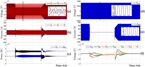
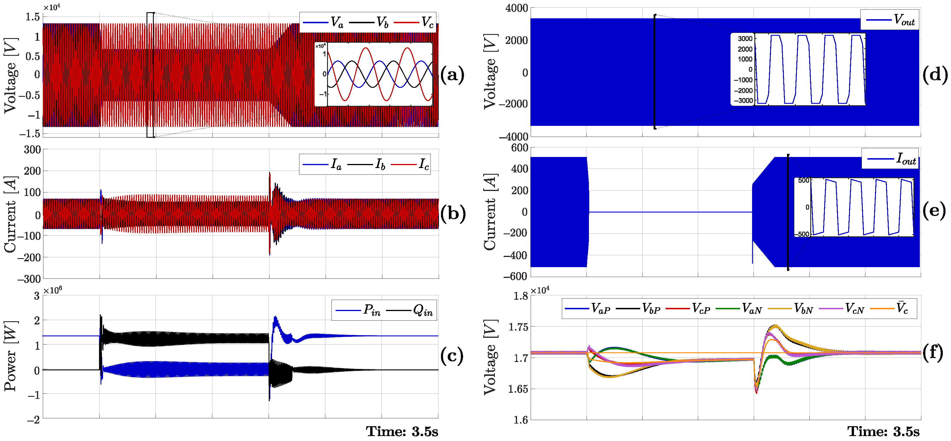
Figure 10 shows the result of a LVRT test applied at the AC input. An asymmetrical grid-voltage fault is imposed, after which the controller switches from normal operation to an LVRT mode that prioritizes reactive current support while limiting the power feed to the DC pots, following the codes studied in [48,49,50].
Figure 10.
Variables of the LVRT test. (a) Input port AC voltages. (b) Input port AC currents. (c) Active and Reactive power. (d) HF port voltage. (e) HF current. (f) CCVs.
In Figure 10a, the three-phase input voltages show the programmed fault, with two phases reduced to half of their nominal magnitude for 1.5 s and then recovering to pre-fault conditions. Figure 10b shows the input currents regulated accordingly: once the fault is detected, the current transitions to the LVRT reference to provide reactive-current injection, while keeping the current magnitude bounded during the disturbance and the subsequent recovery transient. This behavior is reflected in Figure 10c, where the input active power is driven to zero during the fault, while the reactive power is increased to provide grid support. After fault clearance, both powers return to their nominal references.
The coordination between the S-MMC side and the P-MMC side by the HF link is shown in Figure 10d,e. In Figure 10d, the HF-port voltage remains properly synthesized throughout the event, indicating that the HF stage stays commutated even when power transfer is stopped. Consistently, Figure 10e shows the HF current being regulated to zero during the fault interval to prevent overcurrents. Following fault clearance, the HF current is re-established with a ramped profile to avoid power overshoot. Finally, Figure 10f illustrates the CCV behavior during LVRT. The average CCV magnitude decreases throughout the fault, since no active power is supplied to the converter to maintain voltage regulation. This temporary imbalance is resolved once the fault is cleared.
5. Conclusions
This paper presents a hierarchical control system and a systems-level integration scheme for a multi-port, bidirectional SP-MMC charging system. The SP-MMC topology provides modular, isolated, and multiple DC EV charging options. The demonstrated novelty lies in the integration of the control layers, which manage the dynamics of power conversion and the interaction of the six concurrent high-power ports.
The proposed topology and control system were evaluated using MIL simulations implemented in PLECS. The results verify the correct dynamic response during charging, V2G operation, and LVRT operation. The grid, S-MMC, HF stage, and DC ports were regulated while floating capacitor voltages were maintained within the allowed range. Quantitative performance indicators include DC-link voltage ripple below 2% of the nominal value, settling times below 500 ms, accurate per-port current tracking, and near-unity power factor at the grid, even under grid-fault conditions.
While the MIL results assume ideal magnetic components, the results provide evidence of the operation of the proposed control architecture at a system level. Future work will focus on hardware implementation and experimental validation, including magnetic co-design, loss optimization, and compliance with grid-code requirements under extreme operating conditions. In addition, robust nonlinear controllers will be explored to benchmark and enhance the PI/PR loops under abrupt port/grid disturbances, while extending capacitor-voltage balancing robustness checks to initial dispersion and fault-tolerant modes. Overall, the proposed SP-MMC-based solution represents a promising and flexible platform for next-generation multi-port fast-charging and V2G-enabled applications.
Author Contributions
Conceptualization, M.D., R.C. and P.W.; Methodology, T.R. and C.R.; Validation, P.W.; Formal analysis, T.R., C.R., M.D. and R.C.; Investigation, T.R., C.R., D.V. and R.C.; Resources, R.C. and P.W.; Writing—original draft, T.R., M.D. and D.V.; Writing—review and editing, T.R., C.R., M.D. and D.V.; Visualization, M.D. and P.W.; Supervision, M.D.; Project administration, M.D.; Funding acquisition, C.R. and M.D. All authors have read and agreed to the published version of the manuscript.
Funding
This research was funded by Agencia Nacional de Investigación y Desarrollo through projects FONDEQUIP EQM200234 and FONDECYT 1230596, Universidad de Santiago de Chile grant number 062413DD-JUVI.
Data Availability Statement
The original contributions presented in this study are included in the article. Further inquiries can be directed to the corresponding author.
Conflicts of Interest
The authors declare no conflict of interest.
References
- International Energy Agency. Global EV Outlook 2024: Moving Towards Increased Affordability; IEA: Paris, France, 2024; Available online: https://www.iea.org/reports/global-ev-outlook-2024 (accessed on 20 April 2025).
- Rivera, S.; Goetz, S.M.; Kouro, S.; Lehn, P.W.; Pathmanathan, M.; Bauer, P.; Mastromauro, R.A. Charging Infrastructure and Grid Integration for Electromobility. Proc. IEEE 2023, 111, 371–396. [Google Scholar] [CrossRef] [Scilit]
- Perez, M.A.; Ceballos, S.; Konstantinou, G.; Pou, J.; Aguilera, R.P. Modular Multilevel Converters: Recent Achievements and Challenges. IEEE Open J. Ind. Electron. Soc. 2021, 2, 224–239. [Google Scholar] [CrossRef] [Scilit]
- Rodriguez, J.; Lai, J.-S.; Peng, F.Z. Multilevel inverters: A survey of topologies, controls, and applications. IEEE Trans. Ind. Electron. 2002, 49, 724–738. [Google Scholar] [CrossRef] [Scilit]
- Diaz, M.; Cardenas, R.; Espinoza, M.; Rojas, F.; Mora, A.; Clare, J.C.; Wheeler, P. Control of Wind Energy Conversion Systems Based on the Modular Multilevel Matrix Converter. IEEE Trans. Ind. Electron. 2017, 64, 8799–8810. [Google Scholar] [CrossRef] [Scilit]
- Karwatzki, D.; Baruschka, L.; Mertens, A. Survey on the Hexverter topology—A modular multilevel AC/AC converter. In Proceedings of the 9th International Conference on Power Electronics—ECCE Asia: “Green World with Power Electronics”, ICPE 2015-ECCE Asia, Seoul, Republic of Korea, 1–5 June 2015; pp. 1075–1082. [Google Scholar] [CrossRef] [Scilit]
- Ji, X.; Xie, F.; Qi, Y.; Ji, Y.; Niu, D.; Yan, Q. A Fast SOC Balancing Method for MMC-BESS Based on Nonlinear Model-Predictive Control. Energies 2025, 18, 2502. [Google Scholar] [CrossRef] [Scilit]
- Dekka, A.; Wu, B.; Fuentes, R.L.; Perez, M.; Zargari, N.R. Evolution of Topologies, Modeling, Control Schemes, and Applications of Modular Multilevel Converters. IEEE J. Emerg. Sel. Top. Power Electron. 2017, 5, 1631–1656. [Google Scholar] [CrossRef] [Scilit]
- Diaz, M.; Cárdenas Dobson, R.; Ibaceta, E.; Mora, A.; Urrutia, M.; Espinoza, M.; Rojas, F.; Wheeler, P. An Overview of Applications of the Modular Multilevel Matrix Converter. Energies 2020, 13, 5546. [Google Scholar] [CrossRef] [Scilit]
- Rojas, A.; Díaz, M.; Rodríguez, J.; Pizarro, P.; Cárdenas, R.; Arias-Esquivel, Y. Hardware-in-the-Loop Validation of a Modular Multilevel Matrix Converter Fault-Tolerant Control Strategy. In Proceedings of the IEEE 42nd Central America and Panama Convention (CONCAPAN XLII), San Jose, Costa Rica, 27–29 November 2024; pp. 1–6. [Google Scholar] [CrossRef] [Scilit]
- Arias-Esquivel, Y.; Cárdenas-Dobson, R.; Uriarte, M.; Díaz, M.; Tarisciotti, L. An Advanced Zero-Error Continuous Control Set Model Predictive Controller for Low Voltage Ride Through of Grid-Connected Power Converters. IEEE Trans. Ind. Electron. 2026, 73, 682–693. [Google Scholar] [CrossRef] [Scilit]
- Atanalian, S.; Sebaaly, F.; Zgheib, R.; Al-Haddad, K. Modular Multilevel Converters for Fast Charging Stations of Electric Vehicles: An Overview. In Proceedings of the IEEE International Conference on Industrial Technology, Orlando, FL, USA, 4–6 April 2023. [Google Scholar] [CrossRef] [Scilit]
- Barresi, M.; De Simone, D.; Ferri, E.; Piegari, L. Variable Submodule Voltage Control for Enhanced Efficiency in DAB-Integrated Modular Multilevel Converters. Energies 2025, 18, 4096. [Google Scholar] [CrossRef] [Scilit]
- Camurca, L.; Pereira, T.; Hoffmann, F.; Liserre, M. Analysis, Limitations, and Opportunities of Modular Multilevel Converter-Based Architectures in Fast Charging Stations Infrastructures. IEEE Trans. Power Electron. 2022, 37, 10747–10760. [Google Scholar] [CrossRef] [Scilit]
- Rodríguez, C.; Uriarte, M.; Espinoza, M.; Ibaceta, E.; Díaz, M.; Espina, E. Control of a Modular Multilevel Converter for Fast Electric Vehicle Charging Applications. In Proceedings of the 2022 IEEE Biennial Congress of Argentina (ARGENCON), San Juan, Argentina, 7–9 September 2022; pp. 1–7. [Google Scholar] [CrossRef] [Scilit]
- Zayed, O.; Elezab, A.; Abuelnaga, A.; Narimani, M. A Dual-Active Bridge Converter with a Wide Output Voltage Range (200–1000 V) for Ultrafast DC-Connected EV Charging Stations. IEEE Trans. Transp. Electrif. 2023, 9, 3731–3741. [Google Scholar] [CrossRef] [Scilit]
- Hannan, M.A.; Ker, P.J.; Lipu, M.S.H.; Choi, Z.H.; Rahman, M.S.A.; Muttaqi, K.M.; Blaabjerg, F. State of the art of solid-state transformers: Advanced topologies, implementation issues, recent progress and improvements. IEEE Access 2020, 8, 19113–19132. [Google Scholar] [CrossRef] [Scilit]
- Ahmad, A.; Qin, Z.; Wijekoon, T.; Bauer, P. An Overview on Medium Voltage Grid Integration of Ultra-Fast Charging Stations: Current Status and Future Trends. IEEE Open J. Ind. Electron. Soc. 2022, 3, 420–447. [Google Scholar] [CrossRef] [Scilit]
- Tu, H.; Feng, H.; Srdic, S.; Lukic, S. Extreme Fast Charging of Electric Vehicles: A Technology Overview. IEEE Trans. Transp. Electrif. 2019, 5, 861–878. [Google Scholar] [CrossRef] [Scilit]
- Iyer, V.M.; Gulur, S.; Gohil, G.; Bhattacharya, S. An approach towards extreme fast charging station power delivery for electric vehicles with partial power processing. IEEE Trans. Ind. Electron. 2020, 67, 8076–8087. [Google Scholar] [CrossRef] [Scilit]
- Shamshuddin, M.A.; Rojas, F.; Cardenas, R.; Pereda, J.; Diaz, M.; Kennel, R. Solid state transformers: Concepts, classification, and control. Energies 2020, 13, 2319. [Google Scholar] [CrossRef] [Scilit]
- Deng, F.; Lü, Y.; Liu, C.; Heng, Q.; Yu, Q.; Zhao, J. Overview on submodule topologies, modeling, modulation, control schemes, fault diagnosis, and tolerant control strategies of modular multilevel converters. Chin. J. Electr. Eng. 2020, 6, 1–21. [Google Scholar] [CrossRef] [Scilit]
- Debnath, S.; Qin, J.; Bahrani, B.; Saeedifard, M.; Barbosa, P. Operation, Control, and Applications of the Modular Multilevel Converter: A Review. IEEE Trans. Power Electron. 2015, 30, 37–53. [Google Scholar] [CrossRef] [Scilit]
- Espinoza, B.M.; Mora, A.; Díaz, M.; Cárdenas, R. Balancing energy and low frequency operation of the Modular Multilevel Converter in Back to Back configuration. In Proceedings of the 10th International Conference Ecological Vehicles and Renewable Energies (EVER), Monte-Carlo, Monaco, 31 March–2 April 2015; pp. 1–9. [Google Scholar] [CrossRef] [Scilit]
- Espinoza, M.; Cárdenas, R.; Díaz, M.; Clare, J.C. An Enhanced dq-Based Vector Control System for Modular Multilevel Converters Feeding Variable-Speed Drives. IEEE Trans. Ind. Electron. 2017, 64, 2620–2630. [Google Scholar] [CrossRef] [Scilit]
- Shao, S.; Chen, L.; Shan, Z.; Gao, F.; Chen, H.; Sha, D.; Dragicevic, T. Modeling and Advanced Control of Dual-Active-Bridge DC–DC Converters: A Review. IEEE Trans. Power Electron. 2022, 37, 1524–1539. [Google Scholar] [CrossRef] [Scilit]
- Jain, A.K.; Ayyanar, R. PWM Control of Dual Active Bridge: Comprehensive Analysis and Experimental Verification. IEEE Trans. Power Electron. 2011, 26, 1215–1227. [Google Scholar] [CrossRef] [Scilit]
- Yousefpoor, M.; Nourbakhsh, G.; Simoes, M.; Woodworth, R.; Fard, M. Overview of Dual-Active-Bridge Isolated Bidirectional DC–DC Converter for High-Frequency-Link Power Conversion System. In Proceedings of the 2017 IEEE Industry Applications Society Annual Meeting (IAS), Cincinnati, OH, USA, 1–5 October 2017; pp. 1–8. [Google Scholar] [CrossRef] [Scilit]
- Rodríguez-Alonso, A.; Sebastian, J.; Lamar, D.G.; Hern, M.M.; Vazquez, A. An overall study of a Dual Active Bridge for bidirectional DC/DC conversion. In Proceedings of the 2010 IEEE Energy Conversion Congress And Exposition (ECCE), Atlanta, GA, USA, 12–16 September 2010; pp. 1129–1135. [Google Scholar] [CrossRef] [Scilit]
- Tong, A.; Hang, L.; Li, G.; Guo, Y.; Zou, Y.; Chen, J.; Li, J.; Zhuang, J.; Li, S. Power flow and inductor current analysis of PWM control for Dual Active Bridge converter. In Proceedings of the 2016 IEEE 8th International Power Electronics and Motion Control Conference (IPEMC-ECCE Asia), Hefei, China, 22–26 May 2016. [Google Scholar] [CrossRef] [Scilit]
- Mi, C.; Bai, H.; Wang, C.; Gargies, S. Operation, design and control of dual H-bridge-based isolated bidirectional DC–DC converter. IET Power Electron. 2008, 1, 507–517. [Google Scholar] [CrossRef] [Scilit]
- Shan, Z.; Jatskevich, J.; Iu, H.; Fernando, T. Simplified Load-Feedforward Control Design for Dual-Active-Bridge Converters with Current-Mode Modulation. IEEE J. Emerg. Sel. Top. Power Electron. 2018. Early Access. [Google Scholar] [CrossRef] [Scilit]
- Zhang, W.; Sun, C.; Alharbi, M.; Hasanien, H.M.; Song, K. A voltage-power self-coordinated control system on the load-side of storage and distributed generation inverters in distribution grid. Ain Shams Eng. J. 2025, 16, 103480. [Google Scholar] [CrossRef] [Scilit]
- Harnefors, L.; Antonopoulos, A.; Norrga, S.; Ängquist, L.; Nee, H.-P. Dynamic analysis of modular multilevel converters. IEEE Trans. Ind. Electron. 2013, 60, 2526–2537. [Google Scholar] [CrossRef] [Scilit]
- Kong, L.; Wang, S.; Praisuwanna, N.; Wang, F.; Tolbert, L.M. Stability Analysis and Controller Design of MMC Considering Control Delay. In Proceedings of the IEEE Applied Power Electronics Conference and Exposition (APEC), New Orleans, LA, USA, 15–19 March 2020; pp. 1884–1890. [Google Scholar] [CrossRef] [Scilit]
- Iyer, V.M.; Gulur, S.; Bhattacharya, S. Small-signal stability assessment and active stabilization of a bidirectional battery charger. IEEE Trans. Ind. Appl. 2019, 55, 563–574. [Google Scholar] [CrossRef] [Scilit]
- Liu, J.; Yang, J.; Zhang, J.; Nan, Z.; Zheng, Q. Voltage Balance Control Based on Dual Active Bridge DC/DC Converters in a Power Electronic Traction Transformer. IEEE Trans. Power Electron. 2018, 33, 1696–1714. [Google Scholar] [CrossRef] [Scilit]
- Kheraluwala, M.H.; Gascoigne, R.W.; Divan, D.M.; Baumann, E.D. Performance Characterization of a High-Power Dual Active Bridge DC-to-DC Converter. IEEE Trans. Ind. Appl. 1992, 28, 1294–1301. [Google Scholar] [CrossRef] [Scilit]
- Meshram, P.M.; Borghate, V.B. A Simplified Nearest Level Control (NLC) Voltage Balancing Method for Modular Multilevel Converter (MMC). IEEE Trans. Power Electron. 2015, 30, 450–461. [Google Scholar] [CrossRef] [Scilit]
- Choi, H.-W.; Kim, S.-M.; Kim, J.; Cho, Y.; Lee, K.-B. Current-balancing strategy for multileg interleaved DC/DC converters of electric-vehicle chargers. J. Power Electron. 2020, 20, 1383–1394. [Google Scholar] [CrossRef] [Scilit]
- Isik, S.; Alharbi, M.; Bhattacharya, S. An Optimized Circulating Current Control Method Based on PR and PI Controller for MMC Applications. IEEE Trans. Ind. Appl. 2021, 57, 5074–5085. [Google Scholar] [CrossRef] [Scilit]
- Zhang, W.; Sun, C.; Wang, Y.; Song, K. A novel voltage-power coordinated control strategy for grid-connected inverters in low-voltage microgrids based on fast non-singular terminal sliding mode. Electr. Power Syst. Res. 2025, 251, 112183. [Google Scholar] [CrossRef] [Scilit]
- Falcones, S.; Ayyanar, R.; Mao, X. A DC–DC Multiport-Converter-Based Solid-State Transformer Integrating Distributed Generation and Storage. IEEE Trans. Power Electron. 2013, 28, 2192–2203. [Google Scholar] [CrossRef] [Scilit]
- Cuoghi, S.; Mandrioli, R.; Ntogramatzidis, L.; Grandi, G. Multileg Interleaved Buck Converter for EV Charging: Discrete-Time Model and Direct Control Design. Energies 2020, 13, 466. [Google Scholar] [CrossRef] [Scilit]
- Chen, W.; Ruan, X.; Yan, H.; Tse, C.K. DC/DC Conversion Systems Consisting of Multiple Converter Modules: Stability, Control, and Experimental Verifications. IEEE Trans. Power Electron. 2009, 24, 1463–1474. [Google Scholar] [CrossRef] [Scilit]
- Maksimovic, D.; Zane, R.; Erickson, R.W. Impact of digital control in power electronics. In Proceedings of the 16th International Symposium on Power Semiconductor Devices and ICs, Kitakyushu, Japan, 24–27 May 2004; pp. 13–22. [Google Scholar] [CrossRef] [Scilit]
- CharIN e.V., Design Guide for Combined Charging System, Version 7, 2019. Available online: https://www.charin.global/media/pages/technology/ccs-specification/c07034e41e-1626949173/design_guide_combined_charging_system_v7.pdf (accessed on 21 November 2025).
- Díaz, M.; Cardenas, R.; Espinoza, B.M.; Mora, A.; Rojas, F. A novel LVRT control strategy for Modular Multilevel Matrix Converter based high-power Wind Energy Conversion Systems. In Proceedings of the 10th International Conference Ecological Vehicles and Renewable Energies (EVER), Monte-Carlo, Monaco, 31 March–2 April 2015; pp. 1–11. [Google Scholar] [CrossRef] [Scilit]
- Lee, W.-G.; Nguyen, T.-T.; Yoo, H.-J.; Kim, H.-M. Low-Voltage Ride-Through Operation of Grid-Connected Microgrid Using Consensus-Based Distributed Control. Energies 2018, 11, 2867. [Google Scholar] [CrossRef] [Scilit]
- Hossain, M.I.; Abido, M.A. Positive-Negative Sequence Current Controller for LVRT Improvement of Wind Farms Integrated MMC-HVDC Network. IEEE Access 2020, 8, 193314–193339. [Google Scholar] [CrossRef] [Scilit]

Disclaimer/Publisher’s Note: The statements, opinions and data contained in all publications are solely those of the individual author(s) and contributor(s) and not of MDPI and/or the editor(s). MDPI and/or the editor(s) disclaim responsibility for any injury to people or property resulting from any ideas, methods, instructions or products referred to in the content. |
© 2026 by the authors. Licensee MDPI, Basel, Switzerland. This article is an open access article distributed under the terms and conditions of the Creative Commons Attribution (CC BY) license.