


Abstract
Bedding planes widely exist in stratified reservoirs and strongly restrict the vertical cross-layer growth of hydraulic fractures. Traditional displacement discontinuity method (DDM) tends to produce spurious negative apertures for compressed weak bedding interfaces and neglects multi-cluster stress superposition in inclined formations. This work proposes an improved DDM incorporating bedding-plane normal-tangential support-stiffness contact constraints together with Mohr–Coulomb-based opening-slip-closure discrimination, which removes non-physical negative-aperture artifacts of closed weak interfaces. The proposed numerical framework is adopted to model fracture initiation, propagation and bedding-interface penetration under multi-fracture interference. Key coupled influences of net pressure, bedding-plane dip angle and fracture-cluster number are quantitatively investigated. Numerical simulations reveal that higher net pressure enhances the lasting cross-layer propagation capacity of hydraulic fractures. Among the examined cases, a bedding dip angle of 60° facilitates fracture penetration through interfaces. Bedding features amplify inter-cluster mechanical interference and lead to asymmetric fracture evolution, tip arrest and interface-parallel fracture propagation, which becomes more pronounced as the number of fracture clusters increases. This study provides theoretical references for multi-cluster fracturing design in low-permeability layered reservoirs.
1. Introduction
Hydraulic fracturing acts as a vital stimulation technology to economically develop low-permeability hydrocarbon reservoirs [1]. Real-world reservoir formations commonly display well-developed layered structures. Neighboring strata differ greatly in geological properties such as bedding dip angle, rock tensile strength and in situ stress, which jointly govern vertical fracture geometry and set upper limits for fracture cross-layer growth [2]. Whether hydraulic fractures can effectively pass through bedding interfaces, penetrate interbeds and build interconnected vertical fracture networks is a core prerequisite for enlarging the stimulated reservoir volume and improving fracturing treatment performance [3]. For field-scale multi-cluster fracturing operations, stress perturbation generated by simultaneous growth of multiple hydraulic fractures can significantly reshape the local stress field that controls vertical fracture extension. This phenomenon may induce multiple engineering risks: suppressed bedding penetration, fracture path deflection, early-time tip arrest and uneven stimulation across strata, which substantially impair the overall treatment effectiveness within layered reservoirs [4,5,6]. Revealing how fracturing operational parameters and formation mechanical properties jointly regulate fracture cross-layer responses is theoretically meaningful and practically valuable. Such knowledge can support multi-cluster fracturing optimization and facilitate fine-grained reservoir stimulation for stratified formations.
Numerical simulation serves as a powerful tool to uncover dynamic fracture propagation mechanisms and quantify how hydraulic fractures evolve while crossing bedded strata. It can well compensate the limitations of laboratory tests, which cannot capture full dynamic fracture evolution deep inside rock formations [7]. Over recent decades, numerical approaches such as the finite-element method (FEM) [8,9], discrete-element method (DEM) [10,11], and semi-analytical models [12] have been extensively adopted to investigate hydraulic-fracture propagation within layered reservoirs. Each method exhibits unique merits alongside practical constraints under different simulation contexts. The FEM requires full-domain mesh discretization [13]. For simulation scenarios involving multi-layer formations and synchronous propagation of multiple hydraulic fractures, refined meshes are often required around fracture tips and interfaces, which may substantially increase computational cost and limit efficiency for large-scale batch parametric studies. As a block-discretization-based technique, the DEM is powerful for capturing rock fragmentation and granular failure; however, careful parameter calibration is required to obtain accurate continuous fracture-penetration trajectories under low-deformation conditions, which may increase pre-processing workload for fracture-dominated problems [14,15]. Semi-analytical models achieve high computational efficiency by adopting reasonable simplifications [16], yet their capability can be restricted when dealing with strong reservoir heterogeneity and complex multi-fracture stress-interference effects. Within this context, the displacement discontinuity method (DDM), a subclass of boundary-element approaches, only performs discretization on fracture and discontinuity surfaces instead of the entire rock domain [17]. For the specific problem focused on in this work—multi-fracture initiation, propagation and bedding-interface interaction—DDM offers competitive computational performance. It should be noted that DDM also has known limitations, which are further summarized in the Section 4 of this manuscript.
Researchers worldwide have conducted extensive studies concerning hydraulic-fracture cross-layer behavior within bedded reservoirs and have built corresponding theoretical frameworks and simulation tools. Experimental and numerical efforts have clarified how inter-layer stress contrast, elastic modulus and fracture toughness govern fracture penetration, tip arrest and deflection. These findings can explain fracture responses under simplified scenarios with horizontal bedding and single-fracture conditions [18,19,20,21].
However, several critical research gaps still persist in current investigations, as supported by recent numerical and experimental studies [22]. From the algorithm perspective, conventional DDM implementations treat weak discontinuities as pure free surfaces without contact-resistance constraints. Under compressive in situ stress states, closed bedding interfaces may yield non-physically negative fracture apertures in simulation outputs, which distorts induced-stress computation and reduces solution reliability [22]. In terms of physical-modeling assumptions, a large body of prior work adopts ideal horizontal-bedding simplifications. Even though many field reservoirs possess inclined bedding structures, how bedding dip modifies crack-tip stress fields and interface-penetration criteria has not been fully quantified [23]. Furthermore, most existing simulation efforts focus on single-fracture scenarios. Multi-cluster fracturing generates superimposed induced-stress fields; nevertheless, few DDM-based models can capture distinctive mechanical behaviors originating from cluster-scale stress interference, such as delayed cross-layer advancement and heterogeneous fracture trajectories [21,24]. From the reservoir-structure viewpoint, numerous numerical models target one isolated bedding interface. Comparatively, relatively few studies have addressed hydraulic-fracture evolution when traversing a series of successive parallel bedding planes, which better represents realistic layered reservoir conditions [25,26].
To fill the above-mentioned research gaps, this work constructs a numerical model for hydraulic-fracture cross-layer propagation. The proposed model is capable of reproducing the whole physical process: fracture initiation, vertical extension and interbed penetration under coupled multi-fracture stress interference for inclined layered formations. The remainder of this paper is structured as follows. Section 2 describes the detailed modeling framework. Section 4 presents discussion of key findings, and main conclusions are summarized in Section 5.
2. Numerical Model
2.1. Fracture Stress–Strain Model
2.1.1. Governing Equations of Hydraulic-Fracture Deformation
Suppose hydraulic-fracture surfaces are discretized into a total of NHF numerical elements. The resultant shear stress and normal stress loaded upon each i-th fracture element are obtained by superposing far-field in situ stress and injected fracturing-fluid pressure, as formulated below:
where and represent shear and normal components of far-field in situ stress, Pa and and are minimum and maximum horizontal principal in situ stress within simulation domain, Pa. Subscripts s and n correspond to the tangential and normal directions of the local coordinate system for the i-th discretized hydraulic-fracture element, respectively. and denote the aggregated shear and normal stresses acting upon the i-th discretized hydraulic-fracture element, in Pa.
The governing equation for the mechanical deformation of hydraulic fractures is written as [9,17,27]
where and are one-dimensional matrices of size N_HF × 1, representing the tangential and normal displacements of discretized hydraulic-fracture elements, respectively and , , and are coefficient matrices with dimension N_HF × N_HF. Their full expanded formulations can be found in prior published studies [17]; Gij is an empirical scalar correction factor which quantifies the effect of finite fracture height on induced stress. Its expression reads [28]
where α = 1, β = 2.3 are empirical constants; dij is the distance between node i and node j; and h denotes fracture height.
2.1.2. Governing Equations of Bedding Planes
All bedding planes within the computational domain are discretized into NBP independent elements. Prior to any intersection with hydraulic fractures, no injected fracturing fluid invades the bedding planes. Frictional resistance develops along the fracture surfaces, and the exterior surfaces of these planes bear the loading of in situ stress.
For each discretized bedding-plane element, the tangential and normal stress components combine two contributions: stiffness-related stress arising from fracture-surface contact, and the far-field in situ stress. and stand for the aggregated tangential and normal stresses imposed on the i-th discretized bedding-plane element, in Pa.
The tangential stiffness-associated stress originates from interfacial friction over fracture surfaces, while the normal stiffness-associated stress derives from normal contact reaction force when fracture surfaces remain in contact. Bedding planes start in a fully closed state with zero initial fracture aperture. Accordingly, the governing deformation equation for these natural discontinuities is expressed as follows:
where , , and are coefficient matrices of dimension NBP × NBP, whose matrix forms are identical to those for hydraulic fractures in Section 2.1.1; and are one-dimensional matrices of size NBP × 1.
Unlike conventional DDM that treats bedding planes as pure discontinuity boundaries without compressive contact constraints, normal-tangential support-stiffness Kn and Ks are introduced to capture contact mechanical responses of compressed bedding-plane surfaces and suppress non-physical negative-aperture artifacts. To evaluate contact stresses originating from such tangential and normal support stiffness, three characteristic mechanical regimes are defined in the present model. When fracturing fluid invades bedding planes, internal fluid pressure forces the two surfaces apart and induces fracture opening. Tangential loads acting on bedding planes can produce shear dilation together with slight aperture increase, while shear stress is bounded by the Mohr–Coulomb yield threshold. For the fully closed state without apparent fracture opening or significant relative shear slip, shear stress is calculated by subtracting the elastic contact component from the total stress. The above regimes are integrated with the Mohr–Coulomb criterion to describe the mechanical behavior of bedding-plane interfaces. Corresponding expressions for normal- and tangential-stiffness-induced stresses under different mechanical regimes are presented below [17].
- (a)
- Opening-mode of Bedding Planes ( 0):
- (b)
- Slip-mode of Bedding Planes ( && ):
- (c)
- Closure-mode of Bedding Planes ( && ):
2.2. Coupled Calculation and Solution for Multi-Fracture Deformation
Bedding planes and hydraulic fractures in the reservoir mutually influence each other when undergoing deformation and failure. Certain stress interference exists even when they do not intersect. Therefore, the governing equations for the deformation of hydraulic fractures and bedding planes under in situ stress during hydraulic fracturing should be solved in a coupled manner. The governing deformation equations for all discretized fracture elements within the computational domain can be expressed as follows:
where , , and are influence-coefficient matrices with dimension (NHF + NBP) × (NHF + NBP).
and are expanded into one-dimensional matrices of size (NHF + NBP) × 1; σs and σn satisfy the following conditions:
Since , , and are functions of rock mechanical properties and spatial coordinates, they serve as known matrices. Removing from Equation (11) yields a direct expression for fracture aperture .
The solved is inserted into Equation (11) to calculate . Iteration proceeds until discontinuity displacements over all discretized fracture elements fulfill the convergence threshold:
where ε denotes the convergence tolerance, taken as 1 × e−5 m; t represents the iterative calculation step.
|Dt+1 − Dt| < ε
2.3. Fracture Initiation and Intersection Criteria
The SIF in fracture tip can be shown [32]:
where KI and KII is the stress intensity factor of different types of cracks, MPa∙m0.5.
Equation (15) is adopted to calculate the stress intensity factors at fracture tips. This formula originates from the classical analytical solution for a single straight crack in an infinite medium under remote loading. It should be emphasized that the displacement discontinuity at tip elements used for SIF calculation is solved from the fully coupled DDM system for all fractures in the domain. The mutual stress shadow induced by adjacent fractures is inherently incorporated into the computed tip displacement discontinuity. Therefore, the multi-fracture interaction effect is not omitted in the final SIF values.
This work applies the maximum circumferential stress (MCS) criterion to predict fracture initiation and propagation directions [33]. The fracture deflection angle θ0 is calculated via the following relation:
where KI and KII is the stress intensity factor (SIF), MPa∙m1/2.
The instability of the HF and NFs can be judged by the mixed-SIF:
where Ke is the mixed-mode stress intensity factor, MPa∙m1/2. When Ke is greater than the fracture toughness KIC, fracture tip is unstable.
The fracture tip propagation length reads [9]
where ΔLmax denotes the historical maximum propagation length of the fracture tip, m.
In this paper, compressive normal stress is negative and tensile normal stress is positive. Shear stress components are defined with respect to the local element coordinate system. The cohesion C, friction coefficient μ, shear stress σs and normal stress σn adopt identical physical definitions as the bedding-plane slip constitutive relations given in Section 2.1.2.
In the judgment of fracture intersection, two criteria must be satisfied simultaneously for intersecting fractures to achieve penetration.
- (a)
- The compressive stress or cementation force acting on the fracture surfaces can sufficiently inhibit the opening and slipping of fracture surfaces [34,35,36,37], which can be specifically expressed by the following formula:
|σs| < C − μσn
- (b)
- The stress ahead of the hydraulic-fracture tip is sufficient to initiate a new fracture on the opposite side of the bedding-fracture surface [38], which can be specifically expressed by the following formula:where T0 represents the tensile strength of the rock (Pa); T(rc, θ) is the maximum principal stress acting on the bedding planes surface (Pa); and rc is the critical radius for the inelastic behavior of the rock, within which linear-elastic fracture mechanics is no longer strictly valid. It is evaluated via the Irwin plastic-zone correction formula [39]:
2.4. Fluid Flow
Simplified flow relations derived from the Navier–Stokes framework are implemented in this model to characterize pressure loss inside fracture voids. For Newtonian fluid, the flow between two parallel smooth fracture walls is described by the parallel-plate analytical solution [40]:
where pf is the fracture-internal pressure, Pa; q is the volumetric flow rate of fluid through the fracture cross-section per unit time, m3/s; hf is the fracture height, m; w is the maximum width of the fracture cross-section, m; x is the fracture length, m; k is the consistency index; and t is the fracturing time.
It should be noted that: Zero fluid loss of fracturing fluid is assumed for all numerical simulations in this study. The governing system is solved by Gaussian elimination. The fluid flow equation and deformation equation are not coupled in this model. The iteration terminates when |Dt+1 − Dt| < ε and ε = 10−5 m.
2.5. Flowchart of Numerical Calculation
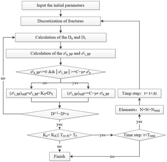
The execution logic of the improved DDM numerical solver is illustrated in Figure 1. The major calculation steps for fracture evolution are outlined sequentially below: ① The solver first imports predefined geomechanical and operational input variables, including maximum and minimum horizontal principal stresses, Young’s modulus, Poisson’s ratio, fracture toughness, fracture count, fracture spacing, fluid pressure inside fractures, perforation depth and perforation angle, etc. ② All bedding planes and hydraulic fractures within the computational domain are discretized and represented by a total of N discontinuity elements. ③ Based on the initial loading state, normal and tangential discontinuity displacements Dn and Ds at each node are computed. ④ The nodal normal and tangential stress components are then solved using the obtained displacement variables Dn and Ds. ⑤ For each element on the bedding planes, the shear stress is evaluated: Once the slip criterion is satisfied, the shear stress is constrained to the yield threshold. If slip does not occur, the shear stress is derived by removing the elastic stress component from the total stress field. ⑥ Iterative updates are executed repeatedly until the change in displacement discontinuity Di converges to the predefined tolerance ε. ⑦ Nodes on bedding-plane and hydraulic-fracture elements that fulfill the fracture propagation criterion are counted and summed as N1 + N2. ⑧ The program checks the fracture propagation criterion. If neither natural bedding planes nor hydraulic fractures meet the propagation condition, the computation terminates. Otherwise, the code judges whether the current iterative time has exceeded the pre-defined time limit. ⑨ When the time step reaches the preset upper bound, the simulation terminates. If not, the algorithm loops back to step ② and continues the calculation.
Figure 1.
Computational flowchart for the improved displacement discontinuity-based numerical solver.
2.6. Model Validation
2.6.1. Induced Stress
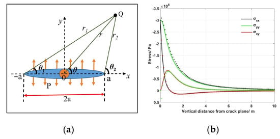
The first benchmark examines the perturbation stress field induced by pressurized fracture deformation. The numerical framework is implemented under plane-strain conditions with a fixed fracture height assumption [41]. The closed-form analytical expressions for stress components surrounding a pressurized crack are adopted for cross-validation [42]:
where Pf denotes fracture injection pressure (Pa); r, r1, r2 represent distances from the field point Q to relevant reference locations around the fracture (m); θ, θ1, θ2 define the angular offsets between the X-axis and lines connecting point Q to crack tips. The corresponding mechanical schematic is displayed in Figure 2a.
Figure 2.
Benchmark for induced-stress verification. (a) Schematic of the mechanical configuration and (b) comparison between computed and analytical stress solutions. Discrete markers represent numerical outputs; solid lines denote analytical results.
The benchmark parameters are configured as follows: constant internal fracture pressure Pf = 3 MPa and fracture half-length a = 1.5 m. The horizontal coordinate of monitoring point Q is fixed at x = 0.5 m, and its vertical coordinate y varies over the range of 1 m to 10 m. As illustrated in Figure 2b, both normal and shear stress magnitudes decay progressively as the separation distance from the fracture surface increases. The numerical predictions closely match the analytical solutions, demonstrating the reliability of the stress calculation module within this model.
2.6.2. Fracture Intersection
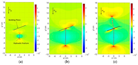
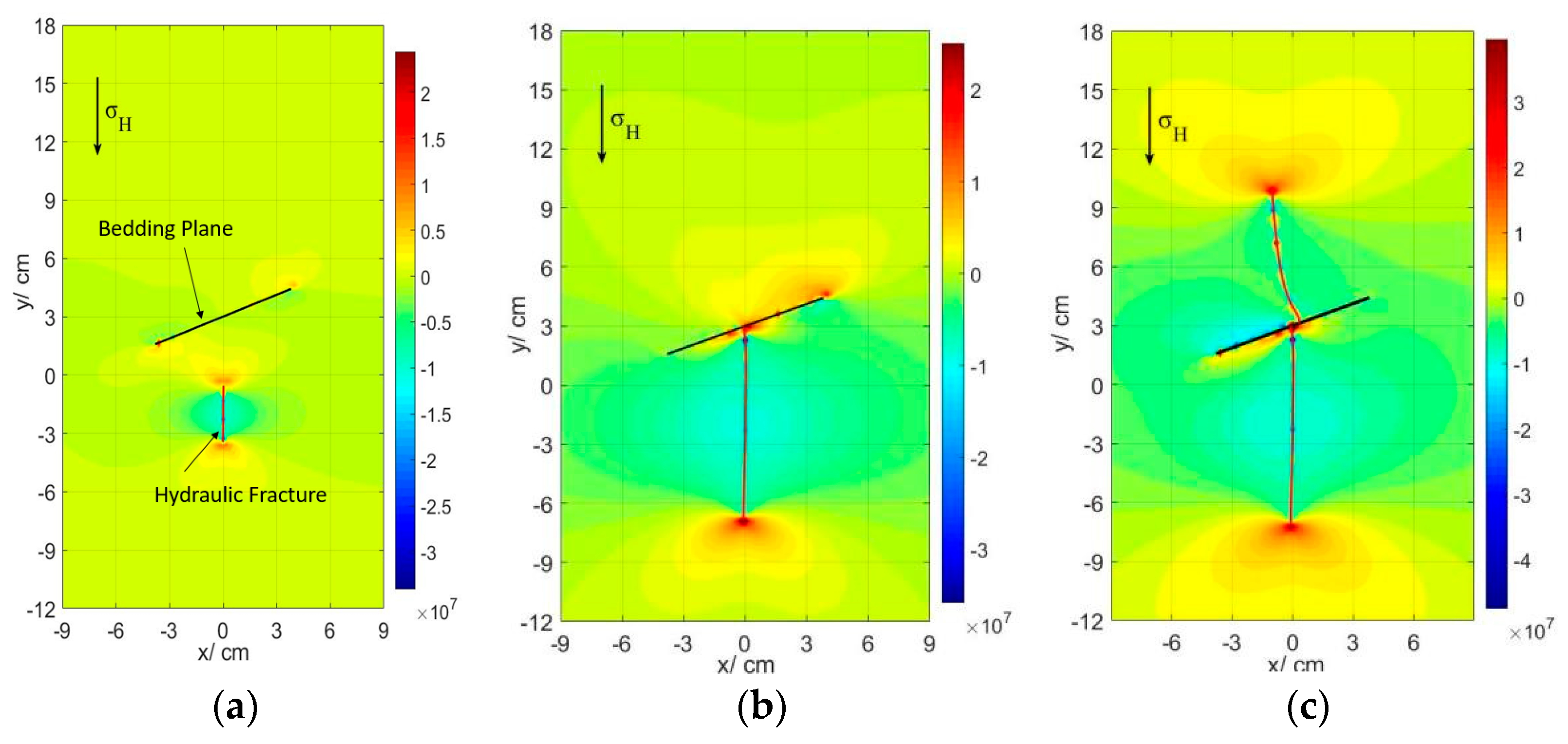
To further validate the capability of our model for simulating hydraulic-fracture-discontinuity interaction, numerical outputs are compared against the experimental findings documented by Lamont and Jessen [43]. Essential computational parameters adopted for this benchmark case are compiled in Table 1. Subplots Figure 3a–c visualize the successive simulated fracture evolution sequences obtained from the improved DDM model. According to the recorded laboratory phenomena from the referenced test, when a hydraulically driven fracture advances toward a pre-existing discontinuity, modest deflection will take place prior to physical contact. Upon reaching the interface, high stress concentration at the intersection spot triggers the emergence of secondary fractures. Such secondary fractures initially propagate roughly normal to the plane of the pre-existing discontinuity instead of extending parallel to the maximum horizontal principal stress. As fracture growth proceeds, the secondary crack tip gradually adjusts its orientation and realigns toward the far-field maximum principal-stress direction. Our numerical simulation reproduces this whole set of mechanical responses: slight pre-contact deflection, the initiation of secondary fractures at the interface, the early-stage perpendicular growth of newly formed cracks, and the subsequent gradual rotation toward dominant in situ stress orientation. The good correspondence between simulated fracture behaviors and reported experimental observations confirms that the proposed numerical framework can reasonably characterize fracture deflection, secondary crack nucleation and re-orientation during hydraulic-fracture-bedding-interface interaction.
Table 1.
Key parameters adopted in the benchmark validation simulation.
Figure 3.
Evolution of hydraulic fracture interacting with pre-existing bedding plane for model validation. (a) Initial propagation of hydraulic fracture; (b) geometrical intersection between hydraulic fracture and bedding interface; and (c) final fracture configuration after secondary crack development.
2.6.3. The Interference Between Two Parallel Fractures
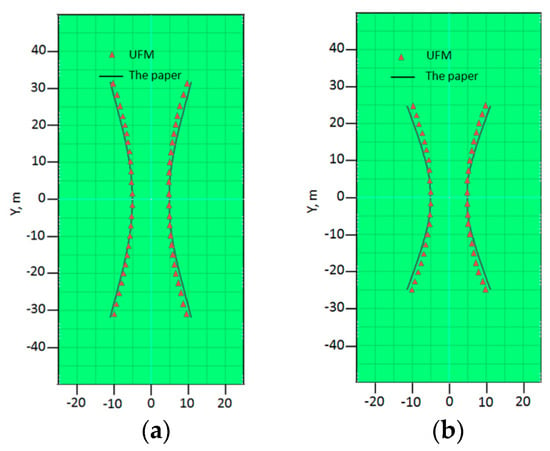
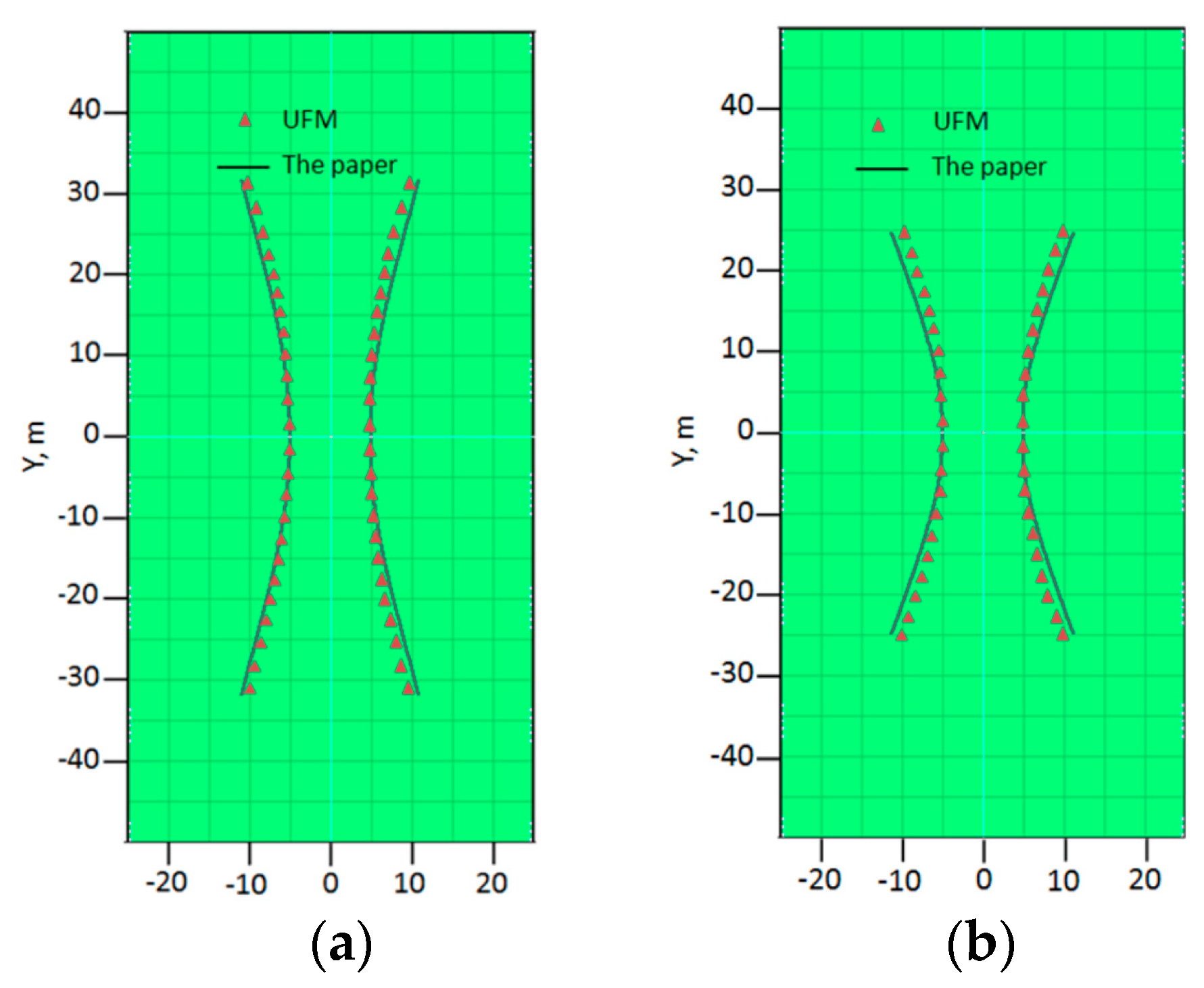
To verify the coupled propagation characteristics of multiple hydraulic fractures under inter-fracture stress shadowing, we perform a benchmark comparison against the numerical predictions reported by Wu et al. [44]. The baseline input parameters adopted for this comparative case are listed as follows: Young’s modulus of 4.35 × 10⁶ psi, Poisson’s ratio of 0.35, maximum horizontal in situ stress of 6903 psi, minimum horizontal in situ stress of 6773 psi, yielding a stress anisotropy of 130 psi, and fracture toughness of 1.000 psi/in0.5. Figure 4 illustrates the comparison of fracture trajectories. The red triangular markers denote fracture paths computed using the numerical framework developed by Wu et al., whereas the black solid lines represent predictions generated by our model. Two parallel hydraulic fractures are initiated with a horizontal spacing of dx = 33 ft and identical vertical coordinate dy = 0; the maximum horizontal principal stress aligns with the y-axis. Driven by the inter-fracture stress interference, the two fractures deflect and repel one another. The fracture geometries predicted by our model show good agreement with the reference results. This comparison demonstrates that the present model can reliably capture the propagation of interacting hydraulic fractures.
Figure 4.
Interference between two parallel fractures. (a) Isotropic, (b) Anisotropy.
2.6.4. Element-Sensitivity Analysis of Mixed-Mode Stress Intensity Factor
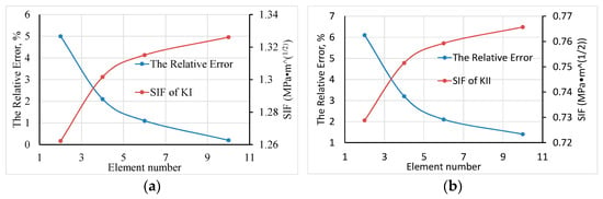
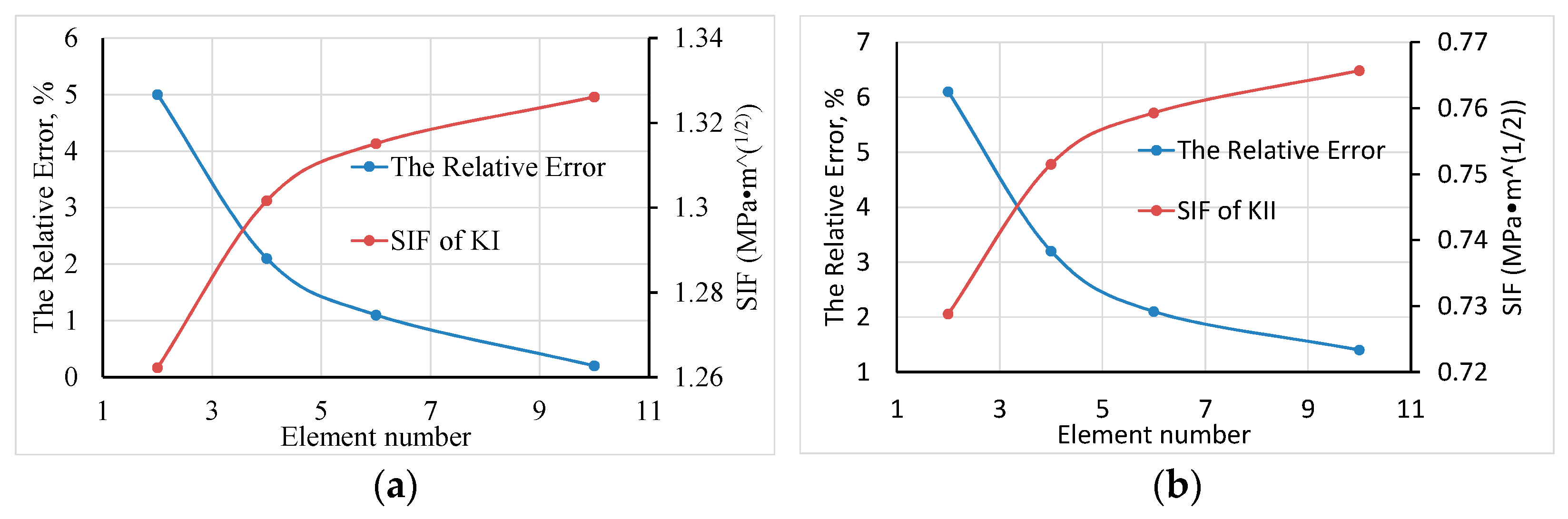
We construct an inclined crack embedded within an infinite thin plate under far-field uniaxial tension, and compare the numerically calculated Mode-I and Mode-II stress intensity factors (KI, KII) with the Westergaard analytical solution [45]. We perform simulations with varying discrete element quantities to quantify relative errors. The tabulated error data will be replotted as curves to illustrate the convergence trend of stress intensity factors with mesh refinement. The injection pressure Pf = −3 MPa and crack half-length a = 1 m. At monitoring point Q, x remains constant at 0.5 m, and y ranges from 0 m to 10 m. Figure 5 presents the calculated stress intensity factors and corresponding relative errors under different discrete element quantities. Subplot (a) describes the trends for Mode-I stress intensity factor KI, while subplot (b) corresponds to Mode-II stress intensity factor KII. As the number of elements increases, the relative error gradually decreases, and the computed SIF values converge toward the Westergaard analytical solution. This demonstrates that sufficient discretization can guarantee numerical accuracy.
Figure 5.
Element-sensitivity analysis for mixed-mode stress intensity factors. (a) Variations in KI and its relative error with element number and (b) variations in KII and its relative error with element number.
3. Simulation Results
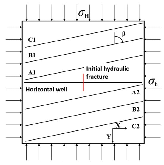
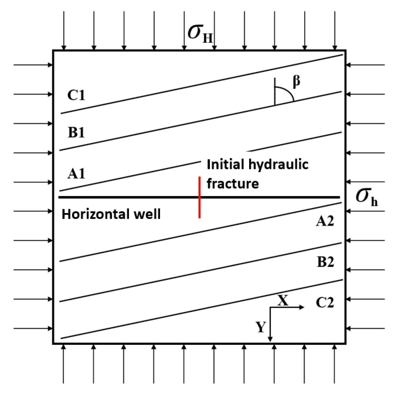
To investigate the propagation behavior of hydraulic fractures intersecting bedding planes, a 300 m × 300 m two-dimensional plane-strain numerical model was constructed, as shown in Figure 6. A horizontal well was located at the model center, with an initial hydraulic fracture perpendicular to the wellbore pre-defined at the mid-wellbore to reproduce the initial propagation path of the main fracture upon fracture initiation. Multiple groups of large-scale weak structural planes were pre-installed above and below the horizontal wellbore, nearly parallel to one another, to simulate the impacts of bedding interfaces on hydraulic-fracture propagation trajectories. Based on their spatial positions relative to the wellbore, the upper interfaces were sequentially numbered C1, B1, and A1, while the lower interfaces were designated A2, B2, and C2. Of these, A1 and A2 are the near-well interfaces that first intersect the main fracture. The dip angle β of natural fractures is defined as the angle between the bedding plane and the direction of the maximum horizontal principal stress σH.
Figure 6.
Schematic diagram of the cross-layer propagation model for hydraulic fractures.
This section quantifies the influences of fracture-internal pressure, natural-fracture dip angle, tensile strength of bedding interfaces, and fracture-cluster count on the cross-layer propagation of hydraulic fractures. The capability of the main fracture to stably traverse multi-order interfaces is taken as the evaluation criterion for continuous cross-layer propagation capacity. Table 2 summarizes the geometric parameters, rock mechanical parameters, in situ stress parameters and fluid properties for the baseline case in this chapter.
Table 2.
Rock-mechanics and operational parameters for simulation cases.
3.1. Influence of Fracture-Internal Net Pressure
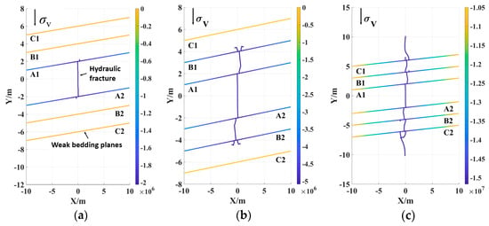
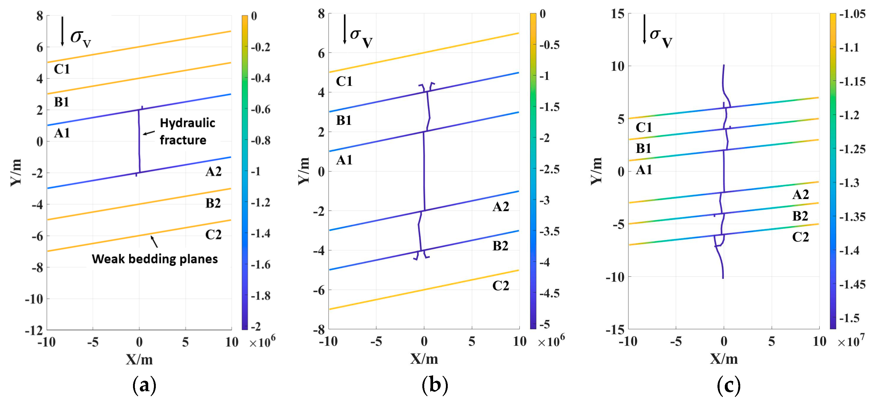
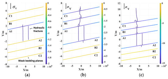
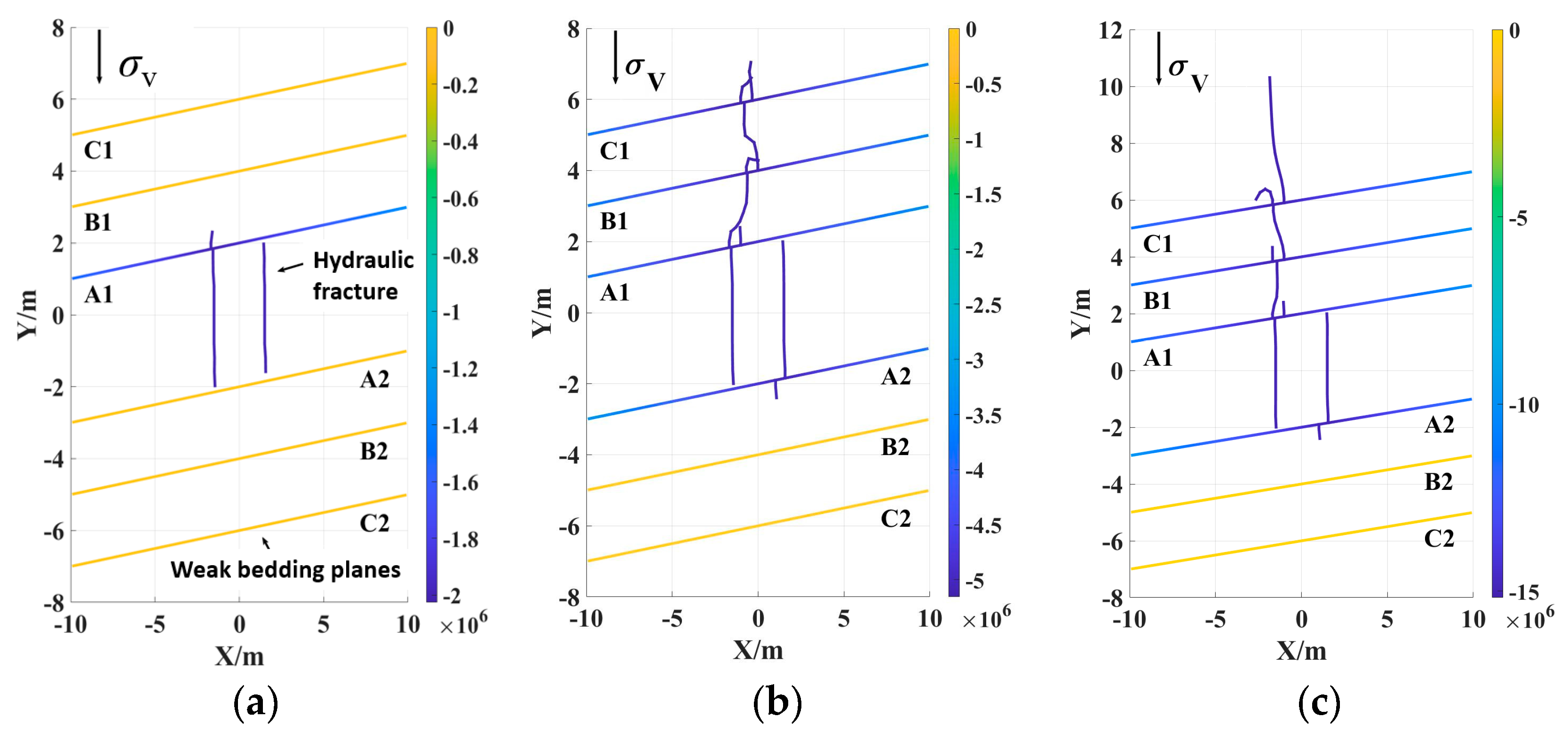
Fracture-internal net pressures of 2 MPa, 5 MPa and 15 MPa were assigned respectively to simulate the propagation of single and dual hydraulic fractures in bedded formations. The simulation results are presented in Figure 7 and Figure 8. Defined as
where pf is the fracture-internal fluid pressure, MPa and pnet is the fracture-internal net pressure, MPa.
pnet = pf − σh
Figure 7.
Cross-layer propagation of single hydraulic fracture under different fracture-internal net pressures. (a) 2 MPa; (b) 5 MPa; and (c) 15 MPa.
Figure 8.
Cross-layer propagation of two-cluster hydraulic fractures under different fracture-internal net pressures. (a) 2 MPa; (b) 5 MPa; and (c) 15 MPa.
As shown in Figure 7, for a single-cluster hydraulic fracture, the net pressure inside the fracture exerts a prominent regulatory effect on the interaction between hydraulic fractures and bedding planes. At a net fracture pressure of 2 MPa, the resistance for hydraulic fractures to cross weak bedding interfaces exceeds the driving force for cross-layer initiation. Consequently, hydraulic fractures hardly penetrate bedding planes and tend to deflect and propagate along bedding planes upon intersection. Injected fracturing fluid rapidly builds up pore pressure within bedding planes and enables far-reaching pressure propagation along bedding planes, which restrains further fracture initiation inside rock matrix. As the net fracture pressure rises, the driving force for hydraulic fractures to overcome bedding-plane impedance increases gradually and improves cross-layer propagation capacity. At a net pressure of 15 MPa, hydraulic fractures can continuously traverse multi-order bedding interfaces and maintain a stable propagation orientation.
Results from Figure 8 indicate that two-cluster fracturing shares a similar evolution law of cross-layer capacity with single-cluster fracturing. Nevertheless, inter-cluster stress interference introduces distinct morphological differences. After penetrating bedding interfaces, the two hydraulic fractures are subjected to superposed induced-stress fields, giving rise to stress shielding and competitive propagation. Ultimately, only one dominant macroscopic hydraulic fracture is generated rather than two independent primary fractures.
It can be seen that at low net pressure, hydraulic fractures are dominated by fluid channeling within bedding planes and slip-propagation along bedding planes, while continuous directional cross-layer propagation can be achieved under high net pressure. Multi-cluster fractures inherit the net-pressure-cross-layer response law of single fractures; nevertheless, the superposition of inter-cluster stress fields triggers competitive propagation. Even if each fracture-cluster possesses cross-layer capacity, multiple independent primary fractures may not necessarily be formed.
3.2. Effect of Dip Angle of Weak Bedding Planes
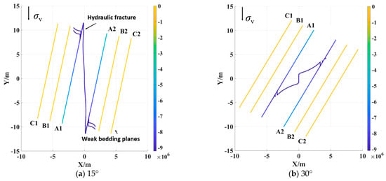
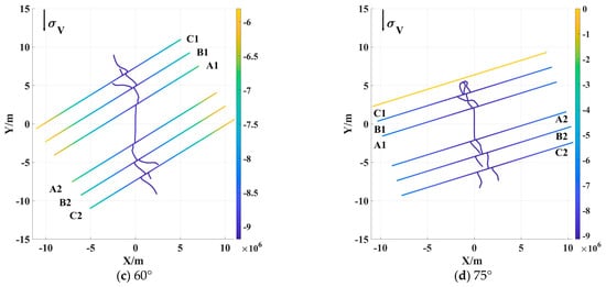
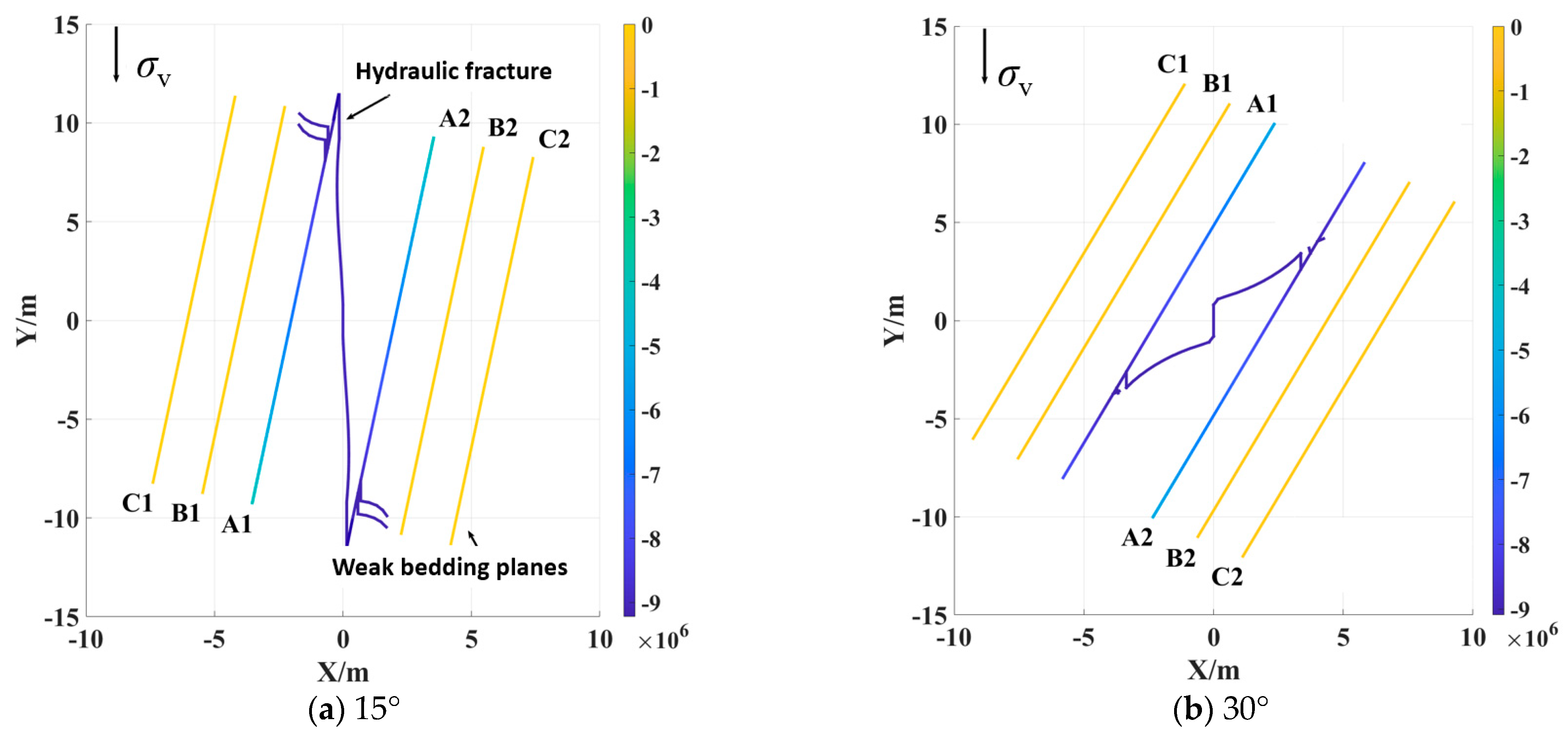
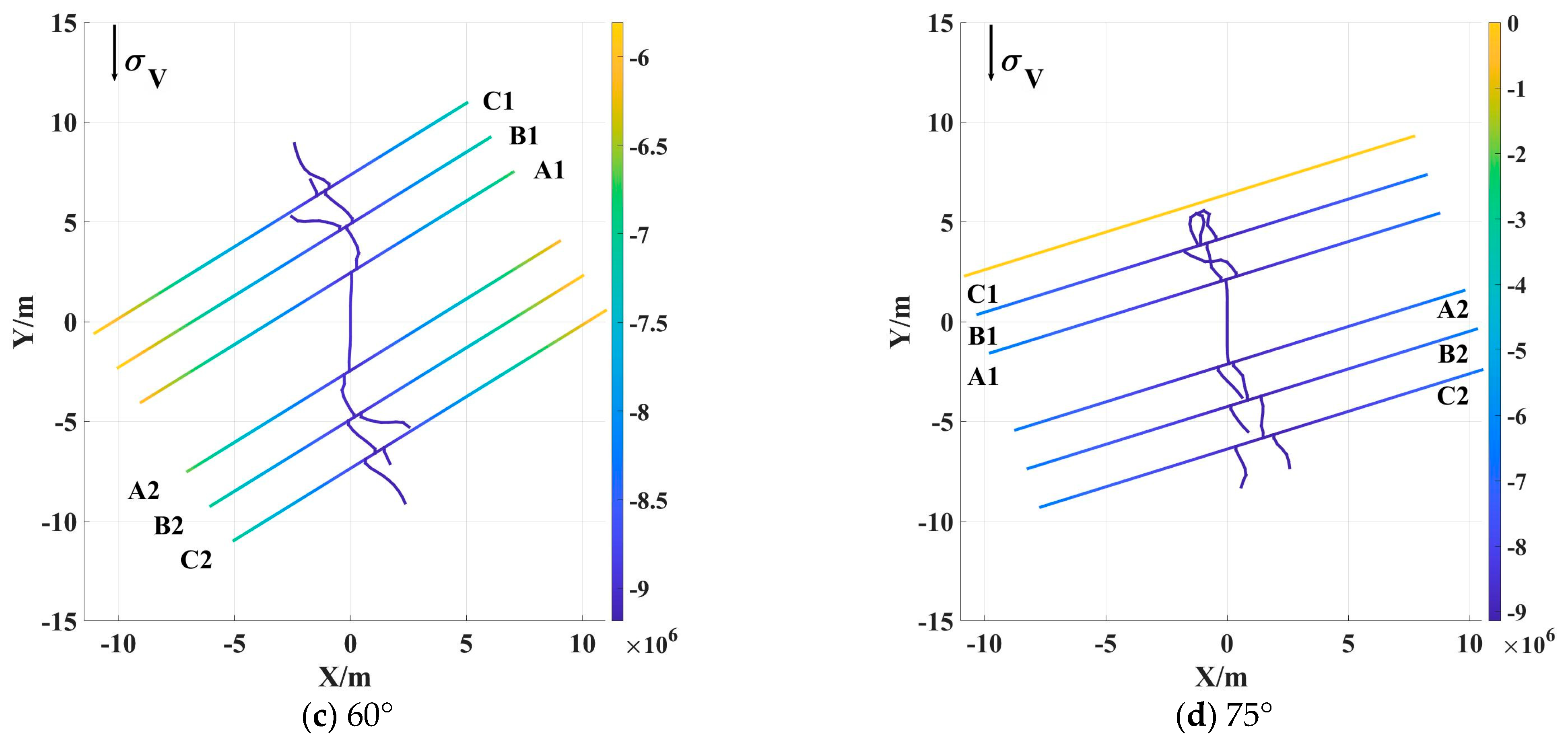
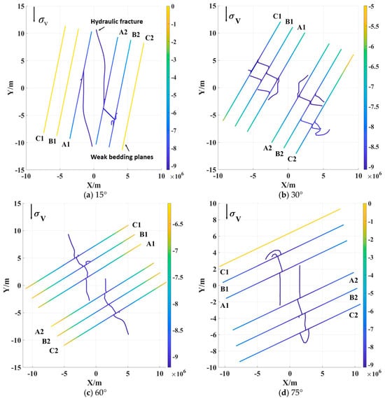
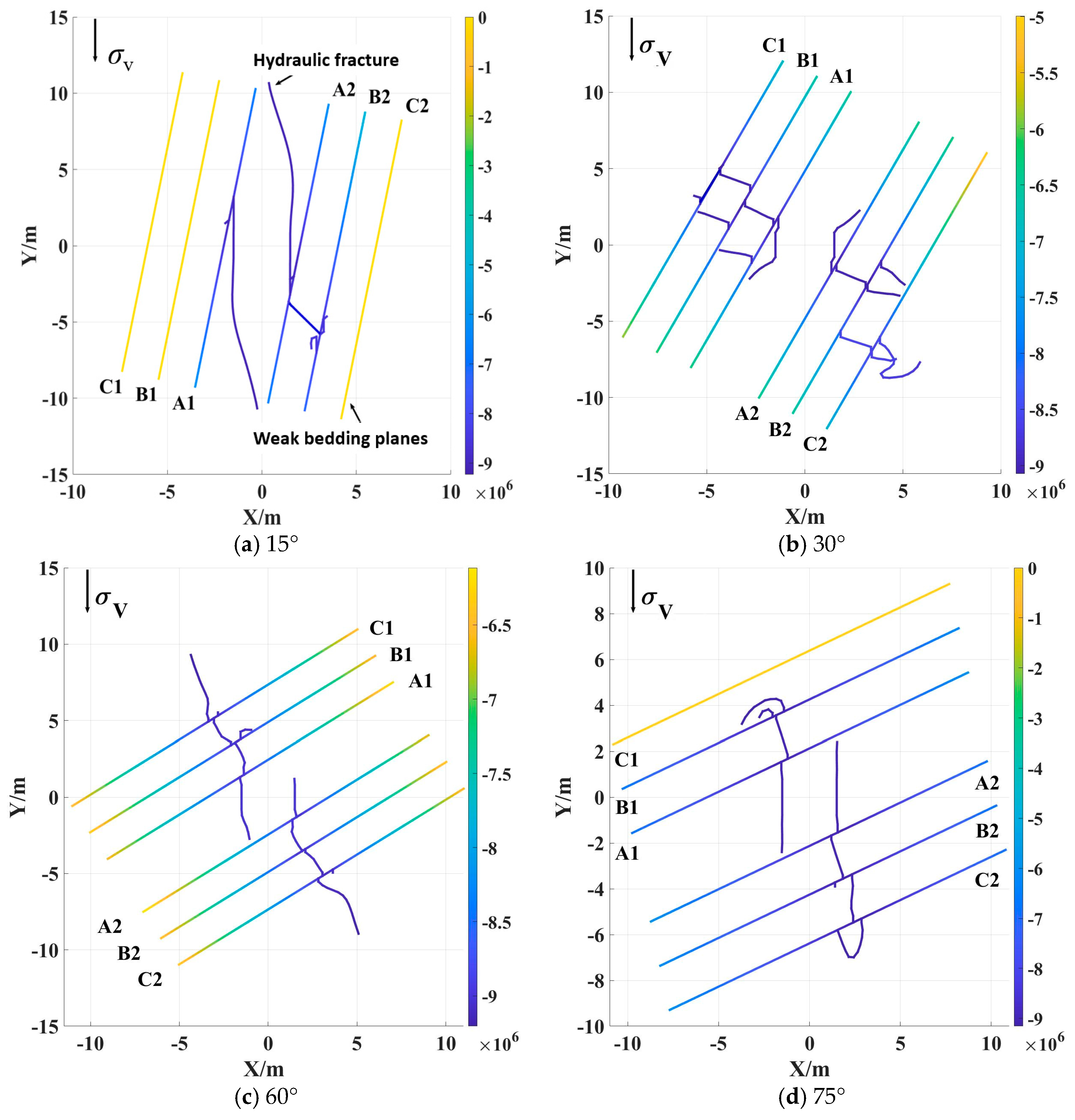
The bedding-plane dip angle β is set to 15°, 30°, 60°, and 75°, respectively, to analyze the influence of approach angle on the cross-layer propagation capacity of hydraulic fractures. The simulation results are shown in Figure 9 and Figure 10. It can be observed that for both single and dual hydraulic-fracture propagation, when β equals 15° and 30°, hydraulic fractures hardly intersect the bedding planes; even after intersection, cross-layer penetration rarely occurs, and fractures tend to propagate along the bedding planes instead. As the angle β increases, the cross-layer propagation capacity of hydraulic fractures gradually improves after intersecting bedding planes. At β = 60°, hydraulic fractures can successfully penetrate three weak planes while maintaining their original propagation direction. When β = 75°, the cross-layer capacity of hydraulic fractures decreases, and the fractures fail to penetrate the C1 layer. Accordingly, when hydraulic fractures intersect bedding planes, either an excessively small or excessively large approach angle will cause fracturing-fluid infiltration into bedding planes, which is unfavorable for the forward propagation of hydraulic fractures. Within the four tested bedding dip angles (15°, 30°, 60°, and 75°), the 60° configuration produces the strongest capacity for hydraulic fractures to penetrate interlayers.
Figure 9.
Single-fracture fracturing under different dip angles of bedding planes.
Figure 10.
Two-cluster hydraulic fractures fracturing under different dip angles of bedding planes.
3.3. Effect of Fracturing Cluster Number
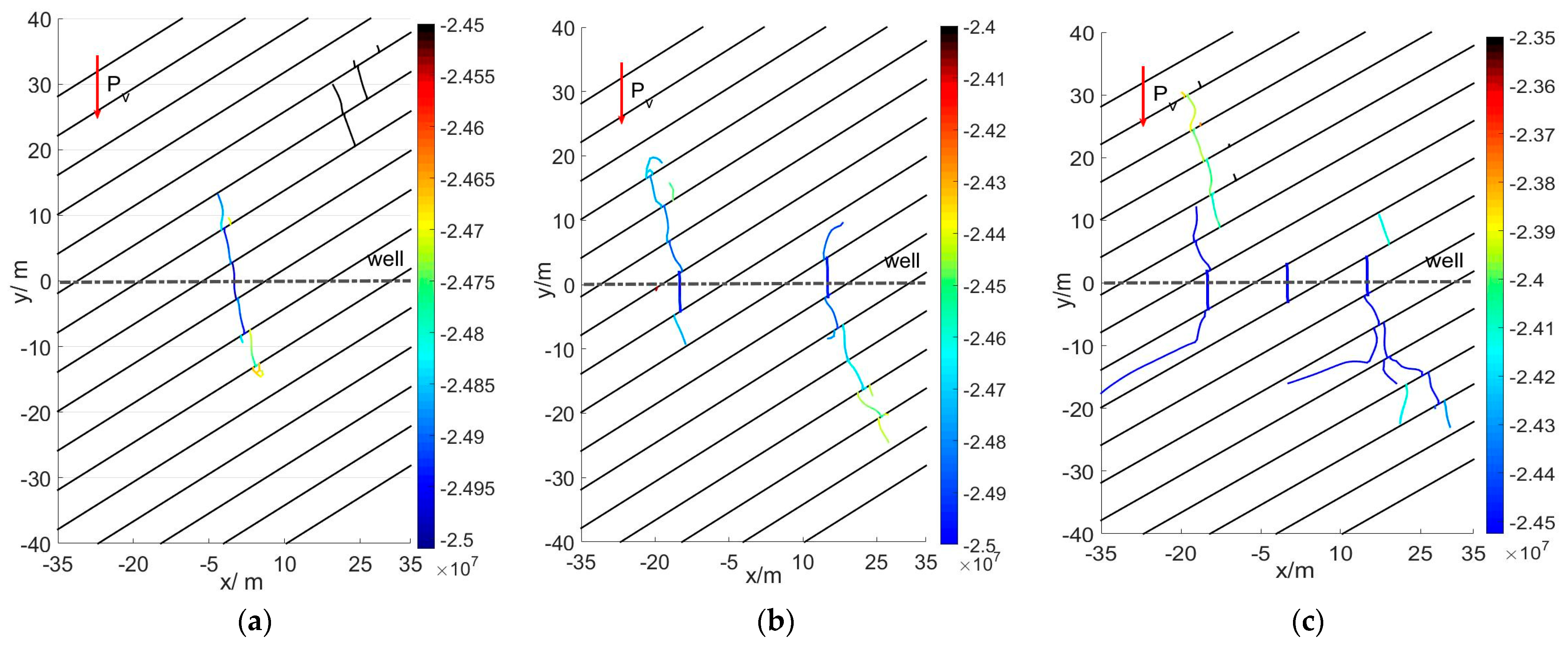
For multi-cluster fracturing operations within bedded reservoirs, the propagation of hydraulic fractures is governed by the combined influence of bedding planes (BPs) and stress interference among adjacent fracture clusters. Numerical simulations are implemented to investigate fracture growth behaviors under such coupled controls. In these cases, the vertical interval between bedding planes is fixed at 6 m, and the bedding dip angle is set to pi/7. The simulated outcomes are presented in Figure 11.
Figure 11.
Cross-layer propagation of fractures under multi-cluster fracturing: (a) single-cluster hydraulic fracture; (b) dual-cluster hydraulic fractures; and (c) three-cluster hydraulic fractures.
As shown in Figure 11a–c, distinct fracture propagation behaviors are observed under single-, dual-, and three-cluster fracturing. In the single-cluster scenario (Figure 11a), the hydraulic fracture expands symmetrically as a primary main fracture and penetrates the bedding plane; although bedding interfaces induce slight lateral deflection of the fracture trajectory, the fracture tip successfully crosses the interface. For dual-cluster fracturing (Figure 11b), inter-cluster fracture interference emerges: the lower tip of the left fracture and the upper tip of the right fracture stop extending after intersecting one bedding plane, while the upper tip of the left fracture and the lower tip of the right fracture achieve successful penetration, and these active fracture tips tend to grow perpendicularly toward the bedding planes under the control of bedding dip angle. Under three-cluster fracturing (Figure 11c), strong stress disturbance from neighboring fractures prevents the middle fracture from crossing the bedding plane after interface intersection, and the lower tips of fractures in both left and right clusters propagate along the strike of bedding planes with propagation lengths ranging from 15 m to 20 m. The simulation results reveal pronounced fracture–fracture interactions during multi-cluster fracturing in reservoirs containing multiple parallel bedding planes. Compared with formations without bedding barriers, pre-existing bedding interfaces amplify the inter-cluster stress shadow and trigger asymmetric fracture propagation; as a result, one fracture tip grows preferentially while the opposite tip loses the capacity to penetrate bedding planes, and fractures may even spread along bedding surfaces and completely lose penetration ability.
4. Discussion
This study investigates the multi-parameter coupling mechanisms governing hydraulic-fracture cross-layer propagation in inclined layered reservoirs, complementing the limitations of previous idealized models that primarily focus on single-fracture scenarios and horizontal-bedding systems. Numerical results indicate that net pressure acts as the dominant driving factor that enables hydraulic fractures to overcome interfacial resistance and achieve effective penetration. Under the specific model and geological conditions adopted in this work, low net pressure tends to induce interfacial slip and fluid channeling, which is consistent with field phenomena whereby low-displacement fracturing commonly yields inadequate inter-layer stimulation. By contrast, elevated net pressure enhances the ability of hydraulic fractures to resist bedding-induced propagation disturbance, thereby improving the multi-layer reconstruction performance.
The bedding dip angle exhibits a dual-influence characteristic on fracture cross-layer behavior within the tested parameter range. Both excessively small and large dip angles constrain vertical fracture penetration. Among the four investigated bedding configurations (15°, 30°, 60°, and 75°), the 60° case shows the most favorable cross-layer propagation performance under the preset model conditions, rather than representing a universally optimal geological threshold. This case-specific quantitative observation provides a reasonable interpretation for the variable fracturing responses commonly encountered in field inclined stratums.
Furthermore, this work reveals that natural bedding interfaces significantly aggravate inter-cluster stress interference during multi-cluster fracturing. Different from the ideal assumption that multiple fractures can propagate independently, the superposition of induced stress generates distinct competitive propagation behavior. This effect triggers asymmetric fracture extension and local propagation arrest, which well explains the uneven stimulation distribution and insufficient effective fracture height frequently observed in field fracturing operations of layered reservoirs.
The improved DDM eliminates the non-physical negative-width defect of weak planes and maintains high computational efficiency for multi-parameter simulation. Still, the model does not account for bedding-plane damage under fluid erosion or proppant transport. Further work may couple fluid–solid-damage equations to realize full-process fracturing simulation. It should also be noted that, as a boundary-element-based tool, the present DDM framework also has inherent limitations, such as difficulties in directly modeling complex rock matrix damage and large-scale plastic deformation, which requires further algorithm improvement in follow-up research.
5. Conclusions
This work develops an improved displacement discontinuity model to simulate multi-cluster hydraulic-fracture cross-layer propagation in inclined layered reservoirs. The coupled effects of net pressure, bedding dip angle and fracturing cluster number are explored under predefined model conditions. The main conclusions are summarized below:
- (1)
- Net pressure dominates cross-layer propagation capacity. Within the tested cases, 2 MPa net pressure triggers fracture deflection, bedding slip and severe fluid channeling, while 15 MPa enables fractures to overcome interface resistance for continuous multi-layer penetration. These pressure values are case-specific and not universal thresholds.
- (2)
- Bedding dip angle exerts strong nonlinear control on cross-layer behavior. Very small or large dip angles suppress vertical penetration. Among the four tested angles (15°, 30°, 60°, 75°), the 60° case achieves better cross-layer performance only for the examined parameter set, and this observation cannot be generalized to all geological settings.
- (3)
- Bedding interfaces amplify inter-cluster stress interference. Dual- and three-cluster simulations show obvious asymmetric fracture growth, including tip arrest and unilateral preferential propagation. This study focuses on cluster-number effects; systematic cluster-spacing tests are not performed, so related inferences on cluster spacing are removed.
- (4)
- Combined multi-cluster induced stress and bedding constraints hinder the generation of multiple independent main fracture networks. Changes in cluster number modulate inter-fracture competition and propagation asymmetry, further affecting vertical reservoir reconstruction.
This study reveals multi-parameter coupling mechanisms for fracture cross-layer growth. The qualitative insights and case-specific quantitative results offer references for multi-cluster fracturing design in similar stratified low-permeability reservoirs.
Author Contributions
Conceptualization, H.-Y.W. and L.-P.Z.; methodology, C.-N.Z. and Q.G.; software, P.Z.; investigation, D.-S.Z.; data curation, Y.-J.Z. and X.-X.W.; writing—original draft preparation, Z.-Y.W.; writing—review and editing, P.Z. All authors have read and agreed to the published version of the manuscript.
Funding
This work was supported by the National Natural Science Foundation of China (Grant Nos. 52404039, U23B2089, 52174029, 52504036), Sichuan Province Mine Salt Mining Engineering Technology Research Center Open Project Funding (No.: cfjs-gczx-002).
Data Availability Statement
Data to support the findings of this study are available upon request from the corresponding author.
Conflicts of Interest
Author Lin-Peng Zhang was employed by Exploration and Development Research Institute of Liaohe Oilfield Company, PetroChina. Author Zi-Yuan Wang was employed by No.1 Gas Production Plant, Sinopec North China Petroleum Company. Author Chao-Neng Zhao was employed by Guangxi Shale Gas Exploration and Development Co., Ltd. The remaining authors declare that the research was conducted in the absence of any commercial or financial relationships that could be construed as a potential conflict of interest.
References
- Zhang, L.-P.; Li, B.; Wang, Y.F.; Wang, S.B.; Zheng, P.; Wu, Z.R. Research and Application of Intensive-Stage Fracturing Technology for Shale Oil in ZN Oilfield. Processes 2025, 14, 131. [Google Scholar] [CrossRef] [Scilit]
- Guo, B.; Xu, Y.; Qu, X.; Li, X.; Liang, S.; Sun, S.; Li, X.; Wang, X.; Niu, Z. Numerical Simulation Study on the Through-Layer Propagation Law of Hydraulic Fracturing in Highly Deviated Wells in Offshore Multilayer Gently Dipping Formations. ACS Omega 2026, 11, 34146–34167. [Google Scholar] [CrossRef] [Scilit] [PubMed]
- Xie, J.; Hou, B.; He, M.; Liu, X.; Wei, J. Fracture-controlled fracturing mechanism and penetration discrimination criteria for thin sand-mud interbedded reservoirs in Suligegas field, Ordos Basin, China. Pet. Explor. Dev. 2024, 51, 1327–1339. [Google Scholar] [CrossRef] [Scilit]
- Sun, D.; Xu, F.; Ma, L.; Li, L.; Han, C. Mechanism of hydraulic fracture propagation and fracturing process optimization in thin-interbedded sandstone-shale reservoirs based on 3D discrete lattice method. Front. Earth Sci. 2025, 13, 1602646. [Google Scholar] [CrossRef] [Scilit]
- Chen, J.; Zhu, Y.; Shao, L.; Liang, L.; Hu, H. Research on Optimization of Construction Parameters of Vertical Cross-Layer Fracturing in Thin Interbedded Coalbed Methane Reservoirs. ACS Omega 2026, 11, 21309–21320. [Google Scholar] [CrossRef] [Scilit] [PubMed]
- Ma, J.; Li, X.; Li, Y.; Wang, X.; Yao, Q.; Yang, S. Numerical simulation of hydraulic fracture extension patterns at interfaces of coal-measure rock strata and a new theoretical prediction model. Simul. Model. Pract. Theory 2025, 140, 103063. [Google Scholar] [CrossRef] [Scilit]
- Ma, J.; Dong, G.; Wang, H.; Li, X. True triaxial hydraulic fracturing experiments and FDEM simulation study of coal-measure rock strata. Sci. Rep. 2026, 16, 15372. [Google Scholar] [CrossRef] [Scilit] [PubMed]
- Chen, X.; Qian, M.; Li, Y.; Huang, Y.; Chang, T.; Kang, X. Numerical simulation of fracture height growth with interference of bedding plane and stiffness contrast in shale reservoirs. Eng. Fract. Mech. 2025, 322, 111161. [Google Scholar] [CrossRef] [Scilit]
- Zheng, P.; Xia, Y.; Yao, T.; Jiang, X.; Xiao, P.; He, Z.; Zhou, D. Formation mechanisms of hydraulic fracture network based on fracture interaction. Energy 2022, 243, 123057. [Google Scholar] [CrossRef] [Scilit]
- Li, W.; Liang, Z.; Zhao, C. Hydraulic fracturing of reservoirs containing rough discrete fracture networks: FDEM-UPM approach. J. Rock Mech. Geotech. Eng. 2026, 2, 1368–1389. [Google Scholar] [CrossRef] [Scilit]
- Shen, H.; Yoon, J.S.; Zang, A.; Hofmann, H.; Li, X.; Li, Q. Impact of injection pressure and polyaxial stress on hydraulic fracture propagation and permeability evolution in graywacke: Insights from discrete element models of a laboratory test. J. Rock Mech. Geotech. Eng. 2025, 17, 2344–2359. [Google Scholar] [CrossRef] [Scilit]
- Al-Rbeawi, S.; Owayed, J.F. Fluid flux throughout matrix-fracture interface: Discretizing hydraulic fractures for coupling matrix Darcy flow and fractures non-Darcy flow. J. Nat. Gas. Sci. Eng. 2020, 73, 103061. [Google Scholar] [CrossRef] [Scilit]
- Han, L.; Zhou, X. A coupled hydro-mechanical field-enriched finite element method for simulating the hydraulic fracture process of rocks subjected to in situ stresses. Acta Geotech. 2025, 20, 1315–1339. [Google Scholar] [CrossRef] [Scilit]
- Wei, X.; Wang, L.; Li, Y.; Ding, J.; Zhang, Z. A Fatigue Cohesive Law-Embedded Finite-Discrete Element Method for Pulsed Hydraulic Fracture Simulation. Int. J. Numer. Anal. Methods Geomech. 2024, 49, 1359–1377. [Google Scholar] [CrossRef] [Scilit]
- Shentu, J.; Lin, B.; Jin, Y.; Yoon, J.S. Investigation of hydraulic fracture propagation in conglomerate rock using discrete element method and explainable machine learning framework. Acta Geotech. 2024, 19, 3837–3862. [Google Scholar] [CrossRef] [Scilit]
- Zhang, J.; Yin, S. A three-dimensional solution of hydraulic fracture width for wellbore strengthening applications. Pet. Sci. 2019, 16, 808–815. [Google Scholar] [CrossRef] [Scilit]
- Zheng, P.; Zhou, D.S.; Zhao, C.N.; Zhang, Z.; Wang, H.Y.; Gao, Q.; Ma, X.P.; Qin, Y.L. Mechanisms of Pre-Existing Fracture Initiation and Complex Fracture Network Formation in Fractured Reservoirs. Int. J. Numer. Anal. Methods Geomech. 2026, 50, 3096–3119. [Google Scholar] [CrossRef] [Scilit]
- Wang, W.; Ma, X.; Zou, Y.; Zhu, X.; Zhang, S.; Liu, L.; Yang, P.; Qi, Y.; Xue, X.; Chen, W.; et al. Experimental and Numerical Research on the Mechanism of Hydraulic Fracture Growth for the Multi-Lithology and Multi-Layered Shale Reservoirs. Rock Mech. Rock Eng. 2025, 59, 971–1000. [Google Scholar] [CrossRef] [Scilit]
- Lv, N.; Chen, X.; Wen, Z.; Wang, L.; An, D.; Kong, L. Fracture Propagation Characteristics and Influencing Factors in Cross-Layer Fracturing of Interlayered Shale Reservoirs. Processes 2026, 14, 2520. [Google Scholar] [CrossRef] [Scilit]
- Bin, W.; Tao, J.; Binggui, X.; Kun, N.; Peng, T.; Yi, Z. Experimental study on hydraulic fracture propagation behavior in heterogeneous shale formations. Front. Energy Res. 2024, 11, 1309591. [Google Scholar] [CrossRef] [Scilit]
- Zheng, H.; Wang, H.; Li, F.; Li, N. Numerical Simulation of the Interaction Between Hydraulic Fracture and the Bedding Plane in Shale Formation. Processes 2024, 13, 6. [Google Scholar] [CrossRef] [Scilit]
- Sun, H.; Qi, H.; Wang, Y.; Tian, Y. Modeling Hydraulic Fracture Propagation and Analyzing Fracture Aperture Morphology Using the Displacement Discontinuity Method. Int. J. Geomech. 2026, 26, 04026163. Available online: https://ascelibrary.org/doi/10.1061/IJGNAI.GMENG-13713 (accessed on 12 June 2026). [CrossRef] [Scilit]
- You, G.; Feng, F.; Zhang, J.; Zhang, J. A Study on Fracture Propagation of Hydraulic Fracturing in Oil Shale Reservoir Under the Synergistic Effect of Bedding Weak Plane–Discrete Fracture. Processes 2025, 13, 362. [Google Scholar] [CrossRef] [Scilit]
- Wen, G.; Zhao, W.; Zou, H.; Huang, Y.; Liu, Y.; Liu, Y.; Zhao, Z.; Wang, C. Optimizing Multi-Cluster Fracture Propagation and Mitigating Interference Through Advanced Non-Uniform Perforation Design in Shale Gas Horizontal Wells. Processes 2025, 13, 2461. [Google Scholar] [CrossRef] [Scilit]
- Lei, Y.; Fan, L.; Wen, X.; Liu, Q.; Liu, Y.; Xing, J.; Tan, J.; Zhu, S. Investigation on the influence of bedding planes on hydraulic fracture propagation in shale based on true triaxial experiments and numerical simulation. Front. Earth Sci. 2026, 14, 1869277. [Google Scholar] [CrossRef] [Scilit]
- Suo, Y.; Zhang, X.; Zhao, Y.; Gao, J.; Zhang, G.; Qi, S.; Chen, X.; Yang, W.; Zhu, Y.; Huang, B. Mechanisms of hydraulic fracture propagation in bedded shale: Insights from finite discrete element simulations. Phys. Fluids 2025, 37, 087144. [Google Scholar] [CrossRef] [Scilit]
- Yang, C.-X.; Yi, L.P.; Yang, Z.Z.; Li, X.G. Numerical investigation of the fracture network morphology in multi-cluster hydraulic fracturing of horizontal wells: A DDM-FVM study. J. Pet. Sci. Eng. 2022, 215, 110723. [Google Scholar] [CrossRef] [Scilit]
- Olson, J.E. Predicting Fracture Swarms—The Influence of Subcritical Crack Growth and the Crack-Tip Process Zone on Joint Spacing in Rock; Special Publications; Geological Society: London, UK, 2004; Volume 231, pp. 73–88. [Google Scholar] [CrossRef] [Scilit]
- Li, K.; Huang, L.-h.; Huang, X.-c. Propagation simulation and dilatancy analysis of rock joint using displacement discontinuity method. J. Cent. South Univ. 2014, 21, 1184–1189. [Google Scholar] [CrossRef] [Scilit]
- Cui, Z.; Sheng, Q.; Leng, X.; Ma, Y. Analysis of the Seismic Performance of a Rock Joint with a Modified Continuously Yielding Model. Rock Mech. Rock Eng. 2017, 50, 2695–2707. [Google Scholar] [CrossRef] [Scilit]
- Barton, N.; Bandis, S.; Bakhtar, K. Strength, deformation and conductivity coupling of rock joints. Int. J. Rock Mech. Min. Sci. Geomech. Abstr. 1985, 22, 121–140. [Google Scholar] [CrossRef] [Scilit]
- Olson, J.E. Fracture Aperture, Length and Pattern Geometry Development Under Biaxial Loading: A Numerical Study with Applications to Natural, Cross-jointed Systems; Special Publications; Geological Society: London, UK, 2007; Volume 289, pp. 123–142. [Google Scholar] [CrossRef] [Scilit]
- Erdogan, F.; Sih, G.C. On The Crack Extension in Plates Under Plane Loading and Transverse Shear. J. Basic Eng. 1963, 85, 519–525. [Google Scholar] [CrossRef] [Scilit]
- Biot, M.A.; Medlin, W.L.; Masse, L. Fracture Penetration Through an Interface. Soc. Pet. Eng. J. 1983, 23, 857–869. [Google Scholar] [CrossRef] [Scilit]
- Blair, S.C.; Thorpe, R.K.; Heuze, F.E. Propagation of Fluid-Driven Fractures in Jointed Rock. Part 2—Physical Tests on Blocks with an Interface or Lens. Int. J. Rock Mech. Min. Sci. Geomech. Abstr. 1990, 27, 255–268. [Google Scholar] [CrossRef] [Scilit]
- Teufel, L.W.; Clark, J.A. Hydraulic Fracture Propagation in Layered Rock: Experimental Studies of Fracture Containment. In Proceedings of the SPE/DOE Low·Permeablllty Gas Symposium, Denver, CO, USA, 27–29 May 1981. [Google Scholar] [CrossRef] [Scilit]
- Helgeson, D.E.; Aydin, A. Characteristics of joint propagation across layer interfaces in sedimentary rocks. J. Struct. Geol. 1991, 13, 897–911. [Google Scholar] [CrossRef] [Scilit]
- Renshaw, C.E.; Pollard, D.D. An experimentally verified criterion for propagation across unbounded frictional Interfaces in Brittle, Linear Elastic Materials. Int. J. Rock Mech. Min. Sci. Geomech. Abstr. 1995, 32, 237–249. [Google Scholar] [CrossRef] [Scilit]
- Irwin, G.R. Analysis of Stresses and Strains Near the End of a Crack Traversing a Plate. J. Appl. Mech. 1957, 24, 361–364. [Google Scholar] [CrossRef] [Scilit]
- Wu, K. Numerical Modeling of Complex Hydraulic Fracture Development in Unconventional Reservoirs. Doctoral Dissertation, The University of Texas at Austin, Austin, TX, USA, 2014. [Google Scholar]
- Kim, J.-H.; Paulino, G.H. On Fracture Criteria for Mixed-Mode Crack Propagation in Functionally Graded Materials. Mech. Adv. Mater. Struct. 2007, 14, 227–244. [Google Scholar] [CrossRef] [Scilit]
- Sneddon, I.N.; Elliott, H.A. The opening of a Griffith crack under internal pressure. Quart. Appl. Math. 1946, 4, 262–267. [Google Scholar] [CrossRef] [Scilit]
- Lamont, N.; Jessen, F.W. The Effects of Existing Fractures in Rocks on the Extension of Hydraulic Fractures. In Proceedings of the 37th Annual Fall Meeting of SPE, Los Angeles, CA, USA, 7–8 October 1962; pp. 203–209. [Google Scholar] [CrossRef] [Scilit]
- Wu, R.; Kresse, O.; Weng, X.; Cohen, C.-E.; Gu, H. Modeling of interaction of hydraulic fractures in complex fracture networks. In Proceedings of Hydraulic Fracturing Technology Conference; Society of Petroleum Engineers: Woodlands, TX, USA, 2012. [Google Scholar] [CrossRef] [Scilit]
- Zheng, P.; Gu, T.; Liu, E.; Zhao, M.; Zhou, D. Simulation of Fracture Morphology during Sequential Fracturing. Processes 2022, 10, 937. [Google Scholar] [CrossRef] [Scilit]

Disclaimer/Publisher’s Note: The statements, opinions and data contained in all publications are solely those of the individual author(s) and contributor(s) and not of MDPI and/or the editor(s). MDPI and/or the editor(s) disclaim responsibility for any injury to people or property resulting from any ideas, methods, instructions or products referred to in the content. |
© 2026 by the authors. Licensee MDPI, Basel, Switzerland. This article is an open access article distributed under the terms and conditions of the Creative Commons Attribution (CC BY) license.