


Abstract
Predicting particle distribution in particulate flows commonly requests numerical simulations. The present work aims to develop analytical expressions for steady particle volume fraction in particulate microchannel plane flows based on an adopted shear-induced lift force model. The initially uniformly distributed particles are injected to the pressure-driven channel flow at an inlet velocity slower or faster than the fluid inlet velocity. The lift-force-driven lateral particle migration develops before the particles match the fluid velocity, which leads the non-uniform particle distribution over the channel cross-section. When the increasing particle Stokes number reaches a critical value, the particle volume fraction reduces to zero at the channel wall or the midline, depending on the sign of lift force coefficient and whether the particle-to-fluid inlet velocity ratio is smaller or larger than the unity. The role of the lift force coefficient in the steady particle distribution is discussed for heavy particles, nanoparticles and gas bubbles, respectively. When the particle-to-fluid inlet velocity ratio is at least one order of magnitude smaller than the unity, two specific locations (symmetric about the midline at a distance about 0.45 the half-channel height from the midline) are identified at which the steady particle volume fraction remains nearly equal to the migration-free value, independent on specific values of the lift force coefficient, the particle Stokes number and the particle-to-fluid density ratio. Comparison of the predicted results with known data available in the literature is made with some qualitative agreement.
1. Introduction
The study of particle migration in particulate flows has initially been inspired by the earlier experiments of Segre & Silberberg [1] on particle-laden circular Poiseuille pipe flow, which confirmed that the dispersed neutrally buoyant solid particles slowly move to a circular ring of the radius about 0.6 the pipe radius. Extensive research effort has also been made to study lateral particle migration in plane channel flow of fluids laden with neutrally buoyant or non-neutrally buoyant particles [2,3,4,5]. Particularly, Phillips et al. [6] developed a diffusive flux model for dense particulate fluids with some adjustable coefficients evaluated by experimental data. For instance, the diffusive model predicts the parabolic-like particle volume fraction which decreases monotonically from the centerline to the wall in axisymmetric Poiseuille pipe flow (e.g., see Figure 10 in [6]). On the other hand, some works have focused on the wall-lift effects on particle migration in bounded pipe and channel flows. For example, based on the wall-lift model (e.g., McLaughlin [7]), Osiptsov & Asmolov showed that the particle migration essentially takes place in the near-wall regions in a dilute suspension flow through the entry region of a plane channel or a circular pipe when the particles and the carrier fluid have equal and uniform inlet velocities [8].
Recently, the lateral particle migration in microchannel flows of particle-laden fluids has attracted significant attention [9,10,11,12]. For microchannel flows of fluids laden with non-neutrally buoyant particles, such as heavy particles in aerosols with the particle-to-gas density ratio of the order of 103 [13,14,15], metallic nanoparticles in metal-water nanofluids with the particle-to-liquid density ratio of the order of 10 [16,17,18], and micro/nanoscale gas bubbles with the gas-to-liquid density ratio of the order of 10−3 [19,20], the buoyancy number (which is proportional to the squared dimension of the microchannel cross-section and inversely proportional to the mean flow speed [21,22,23]) can be much smaller than the unity when the dimension of the microchannel cross-section is smaller than one millimeter (typically, between 10 μm and 200 μm) while the flow velocity is moderately high with a finite Reynolds number (typically, ≤1000). In such cases, the buoyancy effect on lateral particle migration can be less relevant as compared to hydrodynamic forces and then ignored. Thus, it is of fundamental and practical relevance to study the steady particle distribution in particulate microchannel flows in the absence of the buoyancy effect, for instance, with non-neutrally buoyant particles injected at the entrance of a microchannel. To the best of our knowledge, the simulation of particle distribution in particulate channel and pipe flows commonly adopts CFD software and requests non-trivial numerical computation, and explicit expressions for steady particle distribution in particulate channel and pipe flows are rarely reported in the literature.
The present work aims to develop analytical expressions for the steady particle distribution in microchannel plane flows with entrance-injected non-neutrally buoyant particles. The equations of the present model for microchannel plane flows will be formulated in Section 2, and the linearized equations for the particle-disturbed flow field in the dilute limit are given in Section 3. In Section 4, explicit expressions for the steady particle volume fraction are derived for several different cases of the lift force coefficient and the particle-to-fluid inlet velocity ratio. The derived expressions are used in Section 5 to discuss the steady particle distribution in microchannel plane flow of a fluid laden with heavy particles, nanoparticles or gas bubbles, respectively, with qualitative comparison to some available known data. Finally, the main conclusions are summarized in Section 6.
2. Equations of the Present Model
The two-fluid model [24] for particle-laden fluids developed in the author’s recent works is used for the present analysis, its earlier version based on the Stokes drag alone was previously used to study the linear stability of particulate plane flows [25] and Kelvin–Helmholtz instability of particulate fluid interfaces [26], and the derived results were well validated with comparison to the Saffman’s classical results for dusty gases [27] and the results of Michael [28] obtained using the Saffman model, respectively.
2.1. General Equations
Based on the present two-fluid model [24], the hydrodynamics of an incompressible viscous liquid laden with small spherical particles are governed by the modified form of Navier–Stokes equations
with
where x and t are the spatial coordinates and time, ρS and ρf are the mass densities of the particles and the fluid, respectively, p(x, t) is the pressure field of the suspension, and the volume-averaged velocity field v(x, t) and the mass-averaged velocity field vm(x, t) are defined by (3), where vS(x, t) and vf(x, t) are the velocity fields of dispersed particles and the carrier fluid, respectively. Here, the effective density ρ (per unit volume) of the suspension is given by , δ is the particle volume fraction, μ is the effective viscosity of the suspension which can be estimated by the formula with the constant α and the viscosity μf of the liquid in the dilute limit, and and are the gradient and Laplacian operator, and is the gravity.
As derived in Appendix A of [24], the vm(x, t) − v(x, t) relation gives
where
Here, rS is the particle radius, Ca and CL are the dimensionless added mass coefficient and the lift force coefficient, respectively, d/dt denotes the material derivative of the associated velocity field along its own streamlines. As stated below, in the absence of the lift force, the lateral particle migration will not happen in the microchannel flow.
It is stated here that the various lift force models have been developed in the literature which have different physical origins and mathematical forms and the associated lift forces can depend on various particle and flow conditions [10,11,29,30]. As shown in Appendix A of [24], the present analytical model is based on the shear-induced lift force model widely adopted in the literature (see Saffman [31], Auton [32] and Loth & Dorgan [29], and some recent works such as [30,33,34]) with the lift force coefficient CL to be specified. In addition, as illustrated in Appendix A of [24] (see Equation (11) in Magnaudet & Eames [35], or Equations (92)–(95) in Legendre & Zenit [36]), the physical concepts and mathematical equations formulated for solid particle-laden suspensions are applicable to the liquids with dispersed small spherical gas bubbles with the lift force coefficient to be specified.
2.2. Equations for Steady Particulate Plane Flow
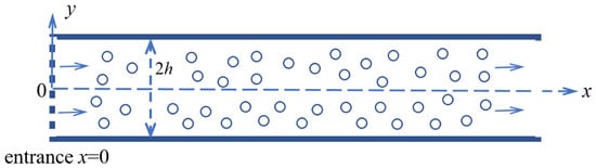
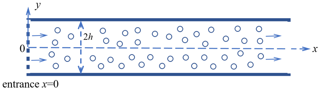
Let us consider the Poiseuille plane flow disturbed by the initially uniformly distributed particles injected at the entrance x = 0 of the channel, as shown in Figure 1, where is the undisturbed velocity field of a pure carrier fluid, h is the half-height of channel and umax is the axial velocity of the carrier fluid at the midline y = 0. It is assumed that the injected particles have the inlet velocity with the uniform particle volume fraction ε (ε << 1) at x = 0, and the buoyancy effect can be ignored.
Figure 1.
Steady Poiseuille channel plane flow with the initially uniformly distributed particles injected at the entrance x = 0 with the inlet velocity (β > 0), where is the undisturbed velocity profile of the carrier fluid, and the buoyancy effect is ignored.
For the steady 2D plane flow in the x-y plane within the channel of height 2h, as shown in Figure 1, with the (x, y, z) coordinate system, we have
Here (um, vm) are the x- and y-components of the velocity field vm(x, t), while (u, v) are the x- and y-components of the velocity field v(x, t). Note that
where the subscript “, ” denotes the partial derivative with respect to x or y. In addition, we have
With the gravity ignored, it is verified that Equations (1)–(4) give 6 nonlinear equations for 6 unknowns (um, u, vm, v, p, δ) as follows:
3. Linearized Equations for the Particle-Disturbed Flow Field
For a clear fluid (δ = 0) without dispersed particles, it follows from the definition (A3) that vm(x, t) = v(x, t), and we have the pressure-driven Poiseuille channel flow
The inlet velocity of particles at the entrance x = 0 (where δ = ε << 1) is βu0(r), while the velocity of the carrier fluid at x = 0 remains u0(r). Thus, it follows from (4) that
With the initially uniformly distributed particles injected to the channel at the entrance x = 0, the Stokes drag-driven particles will eventually catch up with the carrier fluid velocity. With the shear-induced lift force model adopted in the present analysis, the lift force vanishes after the particle velocity matches the carrier fluid velocity; therefore, the lift-force-driven lateral particle migration develops only before the particle velocity matches the carrier fluid velocity.
With the injected particles (δ > 0), let us write the particle-disturbed flow field as
We shall focus on the dilute limit of particle-laden fluids when the volume fraction of particles is much smaller than the unity. With the Einstein formula and the added mass coefficient Ca = 0.5, up to the first powers of δ, the δ-dependent coefficients (μ, ρ, a, b) are expanded as
where is the dimensional relaxation time of suspended particles, and is the modified relaxation time for massless gas bubbles due to the added mass.
The disturbed flow field (u1m, u1, v1m, v1, p1) and the particle volume fraction δ due to the injected particles have the same order of magnitude and all scale with the small parameter ε. Substituting (14) and (15) into (12) and ignoring all nonlinear disturbed terms, the 6 linear equations for (u1m, u1, v1m, v1, p1, δ) give
The complete solution of six coupled partial differential Equations (14a–f) requests numerical computation and is beyond the scope of the present work. It is important for the preset analysis that, as shown below, the steady particle volume fraction δ(x, r) can be determined analytically without solving the complete solution numerically.
4. Explicit Expression for Particle Volume Fraction
In what follows, we shall focus on the steady particle volume fraction δ(x, y). For this purpose, let us define two functions
It is verified from (14c–f) that we have the following three equations for X, Y and δ
Once X, Y and δ are known, if needed, (u1m, v1m) can be expressed in terms of (u1, v1), and then (u1, v1, p1) can be determined from Equations (14a–c) with the boundary conditions on (u1, v1, p1) as the pipe flow problem of a clean fluid with some given variable coefficients and non-homogeneous terms.
It is verified from the relations (3) and that
Thus, up to the leading δ–order terms, we have
At the entrance x = 0, it follows from (20) with (δ = ε, us = βu0(y), u = u0(y) and vs = v = 0) that
Let
It follows from (17, 18) that the two y-dependent roots λ(y) are determined by
It is seen from (23) that the mathematical forms of λ(y) depend on the sign of the right-hand side of (23). For the present linearized leading-order solutions to be valid, X(x, y) and Y(x, y) must remain small for large (x/R). To meet this restriction, it is seen from (22) that λ1(y) and λ2(y) determined by (23) must have non-positive real parts. In what follows, let us consider three different cases.
4.1. Case 1:
In this Case 1, it is seen from (13) that the coefficient CL must be strictly positive and smaller than Thus, the roots are given by
where the roots λ1 and λ2 are given by (24) with the “+” and “−”, respectively, and q is a dimensionless positive number (for instance, when CL = 0.5), and it is verified that .
For the present Case 1, for λ1(y) and λ2(y) to have non-positive real parts, it is seen from (24) that the particle Stokes number defined below is bounded from above by the restriction condition
It will be confirmed that the restriction (25) does not impose meaningful restriction on all cases discussed in this work, and all examples of the Case 1 discussed below meet the condition (25) easily. Here, for the brevity, the particle Stokes number is defined by (25) based on the coefficient a0 given in (13).
It is verified from (17), (18), (22) and the boundary conditions (21) at x = 0 that
Under the condition (25), λ1(y) and λ2(y) have strictly negative real parts, then X(x, y) and Y(x, y) given by (26) vanish on the wall y = ±h for all x > 0, and it follows from (15) and (20) that the axial and vertical velocities (uS, vS) of particles vanish at the channel wall provided that the volume-averaged velocities (u, v) of the particle-laden fluid meet the non-slip boundary conditions at the channel wall, as commonly requested.
It follows from (16), (21) and (26) that
Thus, we have the particle volume fraction δ(x, y) normalized by the parameter ε as follows (a derivation is given in Appendix A, where the integral variable t is the axial coordinate along the channel):
It is verified that expression (28) is well defined in the limit case when y approaches ±h, and expression (28) has a well-defined limit value when q approaches zero.
Since the steady particle distribution over the channel cross-section after the lateral particle migration settles down is of major interest, let us consider the steady particle volume fraction for sufficiently large values of x/h, which is mathematically equivalent to the limit valve of (28) when x approaches infinity. In this limit case, we have (a derivation is given in Appendix A)
Thus, in Case 1 with the lift coefficient CL within the range limited by (24), explicit expression (29) gives the steady particle volume fraction over the channel cross-section after the lateral particle migration stops. In particular, the condition (25) imposed on the particle Stokes number ensures that the denominator in (29) does not vanish. To the best of our current knowledge, explicit expressions (28) and (29) derived here do not find similar counterparts in the existing literature, which may provide useful results to predict the steady particle distribution in channel plane flows with entrance-injected particles when the buoyancy effect can be ignored.
In particular, it is seen from (29) that when is much smaller than the unity and then can be ignored, we have
It is seen from (30) that the right-hand side of (30) vanishes at the location y = ±h/√5 ≈ ±0.45h and, therefore, the particle volume fraction δ is equal to the migration-free limit value (βε), regardless of the specific values of the lift force coefficient, the particle Stokes number and the particle-to-fluid density ratio.
In order to find out the condition for Equation (30) to be met, let us discuss two different cases when the particle-to-fluid inlet velocity ratio β is smaller or bigger than the unity, respectively.
4.1.1. Slowly Injected Particles: 0 < β < 1
In the case 0 < β < 1, it is readily seen from (30) that the critical Stokes number of particles, defined by the condition that the steady value δ(y) when x approaches infinity vanishes at the channel wall y = ±h, is given by
It is verified from (31) that for to be much smaller than the unity, the sufficient condition is that either the parameter β is at least one order of magnitude smaller than the unity, or the lift coefficient CL approaches from below while the value of β is finite but not close to 1. When the mentioned sufficient condition is met, it follows from (30) and (31) that the particle volume fraction δ(y) becomes negative at the channel wall (y = ±h) when the particle Stokes number is bigger than the critical particle Stokes number given by (31). Therefore, the present analysis for the Case 1 defined by (24) with β < 1 is restricted to the particle Stokes number not bigger than the critical particle Stokes number (31), and all results presented here cannot be applied when the particle Stokes number is bigger than the critical particle Stokes number.
4.1.2. Fast Injected Particles: β > 1
In the case β > 1, it is readily seen from (30) that the critical Stokes number of particles, defined by the condition that the steady value δ(y) when x approaches infinity vanishes at the midline y = 0, is given by
It is seen from (32) that for to be much smaller than the unity with β > 1, the only possible case is that the lift coefficient CL approaches from below, such as the gas bubbles with CL = 0.5. In this case, it follows from (30) and (32) that the particle volume fraction δ(y) becomes negative at the midline when the particle Stokes number is bigger than the critical particle stokes number given by (32). Therefore, the present analysis for the Case 1 defined by (24) with β > 1 is restricted to the particle Stokes number not bigger than the critical particle Stokes number (32).
4.2. Case 2:
In this Case 2, it is seen from (13) that the coefficient CL must be either strictly negative or positive and larger than , and it follows from (23) that
where the complex roots λ1 and λ2 are given by (33) with the “+” and “−”, respectively, and k is a dimensionless positive number. As discussed below, the Case 2 for the lift coefficient CL defined by (33) could possibly occur for gas bubbles in a liquid [37,38,39,40].
Note that λ1 and λ2 given by (32) are two complex roots, it can be easily verified from (22), (33) and the boundary conditions (21) at x = 0 that
For the present Case 2, λ1(y) and λ2(y) given by (33) have strictly negative real parts for any particle Stokes number, and therefore X(x, y) and Y(x, y) given by (34) and (35) always vanish on the wall y = ±h for all x > 0.
Thus, for the Case 2, it follows from (27) and (35) that the particle volume fraction δ(x, y) is given by (a derivation is given in Appendix B, where the integral variable t is the axial coordinate along the channel)
It is verified that expression (36) is well defined in the limit case when y approaches ±h, and expression (36) has a well-defined limit value when k approaches zero.
Again, since the steady particle distribution over the channel cross-section after the lateral particle migration settles down is of major interest, let us consider the steady particle volume fraction for sufficiently large values of x/h, which is mathematically equivalent to the limit valve of (36) when x approaches infinity. In this limit case, we have (a derivation is given in Appendix B)
Thus, in Case 2 with the lift coefficient CL within the range limited by (33), explicit expression (37) gives the steady particle volume fraction over the channel cross-section after the lateral particle migration settles down.
In particular, it is seen from (37) that when holds, expression (37) gives
It is readily seen that expression (38) has the same form as expression (30) for the Case 1 derived in Section 4.1, provided that q in (30) is replaced by k in (38). Again, the right-hand side of (38) vanishes at the location y = ±h/√5 ≈ ±0.45h; therefore, the particle volume fraction δ remains equal to the migration-free limit value (βε), regardless of the specific values of the lift force coefficient, the particle Stokes number and the particle-to-fluid density ratio.
With the adopted lift force model, the lift force with a positive (negative) coefficient CL will push the particles which lags (leads) the carrier fluid toward the midline (channel wall); therefore, the direction of lateral particle migration in the Case 2 is determined by the sign of product (). In other words, the lift force drives lateral particle migration toward the midline when , or toward to the channel wall when . In order to find out the condition for Equation (38) to be held, let us discuss two different cases with and , respectively.
4.2.1.
In the case , lateral particle migration toward to the centreline develops, and the steady particle volume fraction at the channel wall decreases with increasing particle Stokes number. It is seen from (38) that the critical Stokes number of particles, defined by the condition that the steady value δ(y) when x approaches infinity vanishes at the channel wall y = ±h, is given by
For to be much smaller than the unity, the right-hand side of the second equation in (39) must be much smaller than the unity and the particle Stokes number must be bounded from above by the condition (39). It follows from (38) and (39) that the particle volume fraction δ(y) becomes negative at the channel wall (y = ±h) when the particle Stokes number is bigger than the critical particle Stokes number given by (39). Therefore, the present analysis for the Case 2 defined by (33) with is limited to the particle Stokes number not bigger than the critical particle Stokes number (39).
4.2.2.
In the case , lateral particle migration toward to the channel wall develops, and the steady particle volume fraction at the midline (y = 0) decreases with increasing particle Stokes number. It is seen from (38) that the critical Stokes number of particles, defined by the condition that the steady value δ(y) when x approaches infinity vanishes at the midline y = 0, is given by
For to be much smaller than the unity, the right-hand side of the second equation in (40) must be much smaller than the unity and the particle Stokes number must be bounded from above by the condition (40). Again, it follows from (38) and (40) that the particle volume fraction δ(y) becomes negative at the midline (y = 0) when the particle Stokes number is bigger than the critical particle Stokes number given by (40). Therefore, the present analysis for the Case 2 defined by (33) with is restricted to the particle Stokes number not bigger than the critical particle Stokes number (40).
4.3. Case 3:
In this Case 3, it follows from (13) that the coefficient CL must be zero or equal to . Since the lateral particle migration will not happen in the case CL = 0, let us focus on the case .
When , we have , and it follows from (17), (18) and the boundary conditions (21) that
Furthermore, it is verified from (42) that
Therefore, it follows from (27) and the boundary conditions (21) that
In particular, when x approaches infinity, expression (44) gives
It is readily seen that expression (45) is identical to the previous result (30) for the Case 2 derive in Section 4.2 at the limit . Therefore, the Case 3 can be considered as a special limit case of the Case 2 provided that the Case 2 is redefined by the extended condition .
5. Results and Discussions
To the best of our current knowledge, the explicit expressions derived in Section 4 for the steady particle volume fraction in a channel plane flow do not find similar counterparts in the literature. In what follows, the derived expressions are applied to discuss the normalized steady particle volume fraction (δ(x, y)/ε) through the channel (x > 0, −h ≤ y ≤ h), with qualitative comparison to available known data.
It is seen from the derived expressions that the steady particle volume fraction δ(x, y)/ε depends on the lift coefficient CL, the particle-to-fluid inlet velocity ratio β, the particle-to-fluid density ratio () and the particle Stokes number defined in (25). It can be easily verified (omitted here) from (16)–(18) that the lateral particle migration will not happen when the lift coefficient CL = 0. Clearly, in the absence of lateral particle migration, the steady particle volume fraction will remain uniform over the channel cross-section if the injected particles are uniformly distributed at the entrance with the initial value δ = ε. In such a case, the steady particle flux at all cross-sections along the channel remains equal to its value at the entrance, and therefore the migration-free value of the steady particle volume fraction along the channel will remain equal to (βε), where β is the particle-to-fluid inlet velocity ratio. As shown below, the sign of the lift coefficient CL changes the direction of the lateral particle migration, although the absolute value of CL has a moderate effect on the steady particle distribution.
5.1. Exponentially Converging Particle Volume Fraction
The Stokes drag depends on the slip velocity between the particles and the carrier fluid, and the Stokes drag-driven particles will eventually match the carrier fluid velocity. With the shear-induced lift force model adopted in the present analysis, the lift force vanishes and the lift-force-driven lateral particle migration stops after the particle velocity matches the carrier fluid velocity. Here, let us first confirm that the particles will quickly match the fluid velocity within a finite axial distance from the entrance, after which the lift-force-driven lateral particle migration stops and the particle volume fraction remains unchanged along the channel as x approaches infinity.
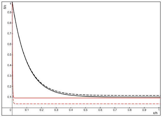
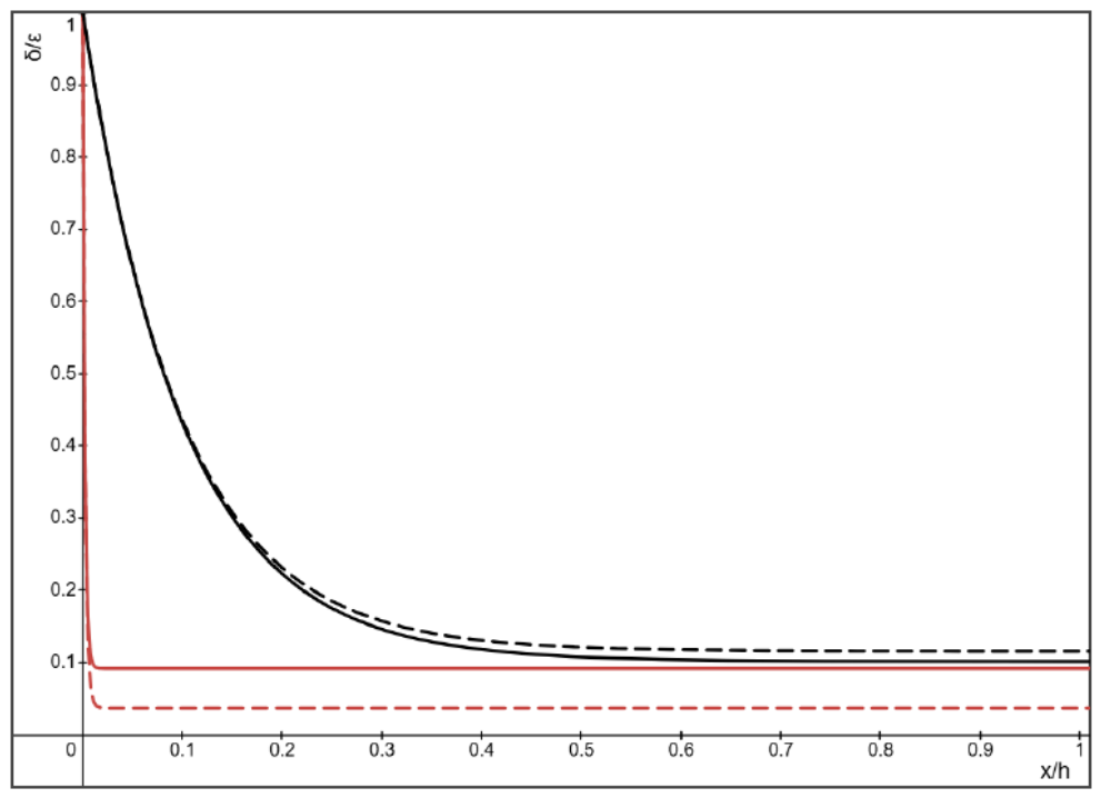
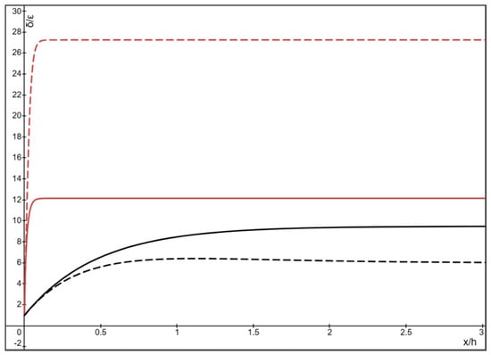
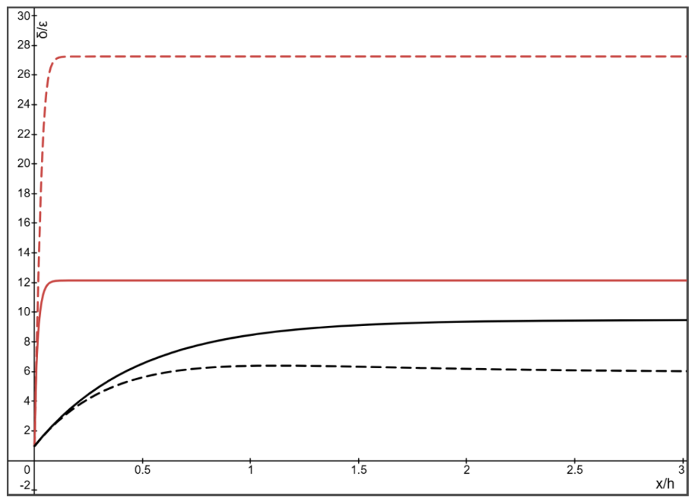
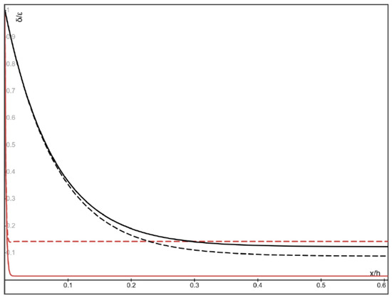
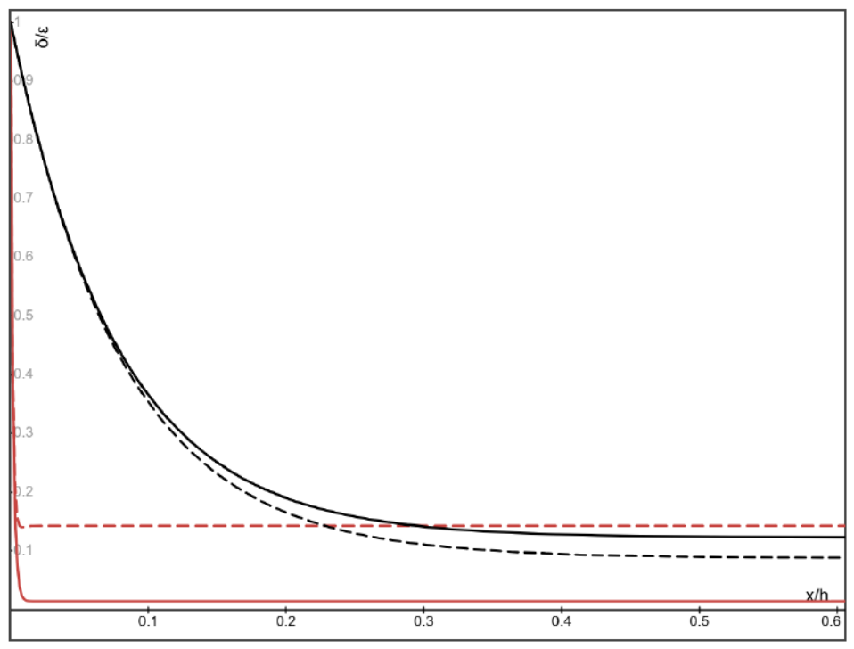
For this purpose, let us first consider two examples of Case 1 studied in Section 4.1 when the particle-to-fluid inlet velocity ratio β = 0.1 and 10, with the same specific density ratio () (such as the aluminum-water nanoparticles) and two different lift coefficients CL = 0.5 and 4, respectively. Thus, the normalized particle volume fraction (δ/ε) is shown in Figure 2 and Figure 3 for β = 0.1 and 10, for the particle Stokes number = 0.1 and 0.5, respectively. Here, the moderate values of are chosen so that the associated particle volume fraction remains non-negative everywhere.
Figure 2.
The normalized particle volume fraction δ(x)/ε given by (28) along the channel with , β = 0.1 and , at the midline y/h = 0 (higher curves) and the wall y/h = ±1 (lower curves), respectively, where the solid curves for the lift coefficient CL = 0.5 and the dashed curves for CL = 4.
Figure 3.
The normalized particle volume fraction δ(x)/ε given by (28) along the channel with , β = 10 and , at the midline y/h = 0 (lower curves) and the wall y/h = ±1 (higher curves), respectively, where the solid curves for CL = 0.5 and the dashed curves for CL = 4.
It is seen from Figure 2 that, with the positive lift coefficient CL and slowly injected particles (β < 1), the lift-force-driven lateral particle migration toward the centerline leads to non-uniform particle distribution over the channel cross-section, and the particle volume fraction δ at the centerline is higher than the migration-free value (βε) while its value at the channel wall is lower than (βε). In addition, the non-uniformity of particle distribution over the cross-section increases with the value of the positive lift coefficient CL. On the other hand, it is seen from Figure 3 that, with the positive lift coefficient CL and fast injected particles (β > 1), the lift-force-driven lateral particle migration develops toward the channel wall so that the particle volume fraction δ at the channel wall is higher than the migration-free value (βε) while its value at the midline is lower than (βε). Again, the non-uniformity of particle distribution over the cross-section increases with the increasing value of the positive lift coefficient CL. It is seen from Figure 2 and Figure 3 that the particles quickly match the fluid velocity within a short axial distance from the entrance, after which the particle volume fraction remains essentially unchanged along the channel.
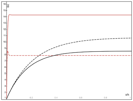
Let us now consider two examples of Case 2 studied in Section 4.2 for the particle-to-fluid inlet velocity ratio β = 0.1 and 10, with the same density ratio () approaching zero (such as gas bubbles in a liquid) and two different lift coefficient CL = 1.0 and −0.5, respectively. Here, it is stated that the possible lift coefficient between −0.5 and 1.0 (−0.5 ≤ CL ≤ 1.0) have been discussed for gas bubbles [37,38,39,40]. Thus, the normalized bubble volume fraction (δ/ε) is shown in Figure 4 and Figure 5 for β = 0.1 and 10, for the bubble Stokes number = 0.08 and 0.2, respectively. Here, similar to the examples shown in Figure 2 and Figure 3 in Section 5.1, the moderate values of are chosen so that the associated bubble volume fraction remains non-negative everywhere.
Figure 4.
The normalized bubble volume fraction δ(x)/ε given by (36) along the channel with β = 0.1, approaching zero and , at the midline y/h = 0 and the wall y/h = ±1, respectively, where the solid curves for CL = 1.0 with the nearly flat solid curve at y/h = ±1, and the dashed curves for CL = −0.5 with the nearly flat dashed curve at y/h = ±1.
Figure 5.
The normalized bubble volume fraction δ(x)/ε given by (36) along the channel with β = 10, approaching zero and , at the midline y/h = 0 and the wall y/h = ±1, respectively, where the solid curves for CL = 1.0 with the nearly flat solid curve at y/h = ±1, and the dashed curves for CL = −0.5 with the nearly flat dashed curve at y/h = ±1.
It is seen from Figure 4 that, when the lift coefficient CL and the inlet velocity ratio β meet the condition , the lift-force-driven lateral bubble migration toward the centerline leads to non-uniform bubble distribution over the channel cross-section, and the bubble volume fraction δ at the centerline is higher than the migration-free value (βε) while its value at the channel wall is lower than (βε). In addition, the non-uniformity of bubble distribution over the cross-section increases with the value of the positive lift coefficient CL. On the other hand, when the lift coefficient CL and the inlet velocity ratio β meet the condition , it is seen from Figure 5 that the lift-force-driven lateral bubble migration develops toward the channel wall so that the bubble volume fraction δ at the channel wall is higher than the migration-free value (βε) while its value at the midline is lower than (βε). Again, it is seen from Figure 4 and Figure 5 that the bubbles quickly match the fluid velocity within a short axial distance from the entrance, after which the bubble volume fraction remains essentially unchanged along the channel.
In all cases shown in Figure 2, Figure 3, Figure 4 and Figure 5, the particle volume fraction exponentially converge to its steady value within a short axial distance from the entrance (x = 0), and then the steady particle volume fraction remains essentially unchanged along the channel as (x/h) approaches infinity. In particular, the exponential terms in (28) and (36) decay much faster than the oscillation of the periodic terms, and it is seen from Figure 2, Figure 3, Figure 4 and Figure 5 that the normalized particle volume fraction converge almost monotonically with increasing axial coordinate (x/h). Consequently, the steady particle volume fraction at larger values of (x/h) can be easily determined by calculating the limit value of δ(x, y) as (x/h) approaches infinity. This largely simplifies the mathematical expression of steady particle volume fraction, and therefore the explicit expressions (29) for Case 1 and (37) for Case 2 can be used to calculate the steady particle volume fraction over the channel cross-section at sufficiently large distance (x/h) from the entrance.
In what follows, we shall discuss the steady particle distribution over the channel cross-section given by expressions (29) or (37) for sufficiently large values of (x/h). In addition, because the present shear-induced lift force model does not take into account of the wall-lift force which could be relevant for particle accumulation near the channel wall, we shall focus on the cases when the lift-force-driven particles will laterally move toward the channel midline.
Thus, the heavy aerosol particles of the density ratio () will be discussed in Section 5.2, the metallic nanoparticles in metal-water nanofluids of the density ratio () will be discussed in Section 5.3, and the gas bubbles in a liquid with and will be discussed in Section 5.4 and Section 5.5, respectively.
5.2. Heavy Particles Injected Slowly with β = 0.1
For heavy aerosol particles and metallic nanoparticles, we have (). Since the Case 2 defined by the condition or unlikely occur for heavy particles and metallic nanoparticles, we shall focus on the Case 1 defined by the condition in Section 5.2 and Section 5.3. In these cases with the positive lift coefficient CL>0, the particles will laterally move toward the channel wall when β > 1 which causes particle accumulation near the channel wall and could not be accurately modeled by the present lift force model (which does not account for the wall-lift force). Therefore, in Section 5.2 and Section 5.3, we shall focus on the case when the particles will move toward the midline with β = 0.1.
For slowly injected heavy aerosol particles of the density ratio () with β = 0.1, the normalized steady particle volume fraction (δ(y)/ε) over the channel cross-section given by (29) with CL=4.0 is shown in Figure 6 for four different particle Stokes number = 0.35, 1.0, 1.5 and 1,81, respectively, where the = 1.81 is the critical particle Stokes number with β = 0.1 and CL = 4 at which the particle volume fraction reduces to zero at the channel wall. It is seen from Figure 6 that the particle volume fraction δ(y)/ε is nearly uniform over the cross-section for the particle Stokes number smaller than or equal to 0.35 (shown by the nearly flat dotted curve in Figure 6). With the increasing particle Stokes number beyond 0.35, it is seen from Figure 6 that the lateral particle migration toward the centerline leads to non-uniform particle distribution over the cross-section. When the particle Stokes number reaches the critical value 1.81, the particle volume fraction δ(y)/ε (shown by the solid curve) vanishes at the channel wall y = ±h. Here, it should be stated that for such large parameter (ρS/ρf) of the order 103, the present leading-order linearized solutions based on the small parameter ε remains valid when ε is at least four orders of magnitude smaller than the unity so that (ερS/ρf) << 1, as commonly assumed in the literature of dusty gases [27].
Figure 6.
The normalized steady particle volume fraction δ(y)/ε over the channel cross-section given by (29) with β = 0.1, and CL = 4, for the particle Stokes number 0.35 (dotted curve), 1.0, 1.5 and 1.81 (solid curve), respectively, in order from the lowest to the highest maximum at the midline y = 0.
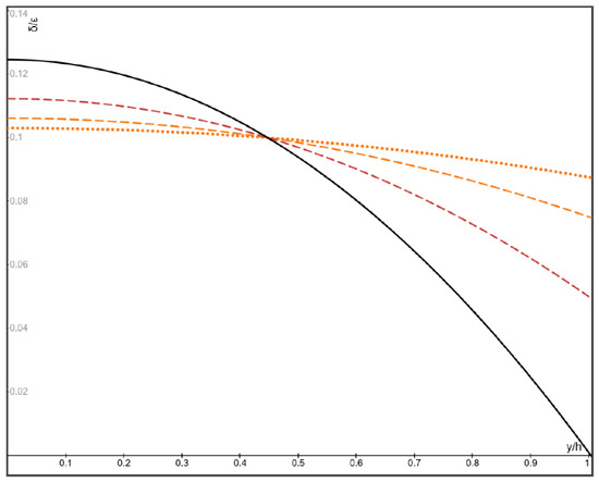
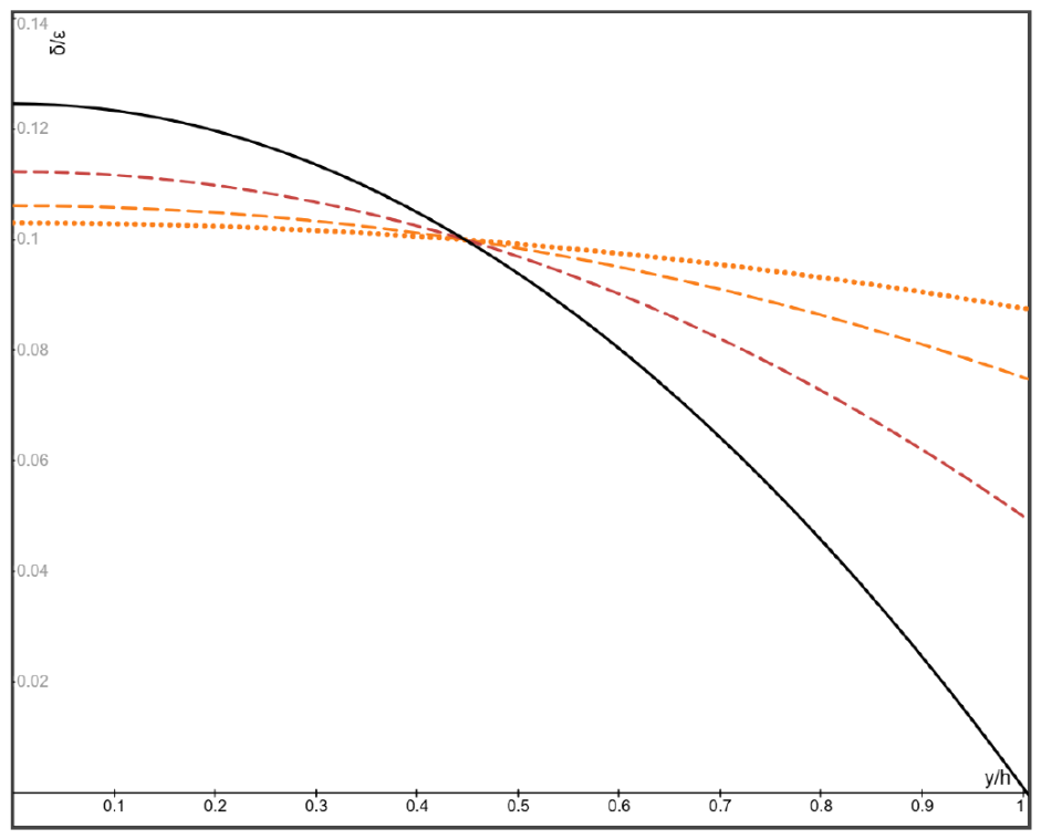
To further illustrate the role of the lift coefficient CL in the steady particle distribution, the normalized particle volume fraction (δ(y)/ε) over the channel cross-section given by (29) with () and β = 0.1 for the particle Stokes number = 1.81 is shown in Figure 7 for four different lift coefficients CL = 0.5, 1, 2 and 4.0, respectively, where the = 1.81 is the critical particle Stokes number with β = 0.1 and CL = 4. It is seen from Figure 7 that the lateral particle migration-induced non-uniform particle distribution increases with the increasing lift coefficient CL. Interestingly, the crossover of the curves for different lift coefficients (with δ/ε = β) is identified at the location around y = ±0.45h. As stated above, to meet the positivity required for the particle volume fraction, all results given by the present analysis are limited to the cases when the particle Stokes number is not larger than the critical particle Stokes number.
Figure 7.
The normalized steady particle volume fraction δ(y)/ε over the channel cross-section given by (29) with β = 0.1, and , for CL = 0.5 (dotted curve), 1.0, 2.0, and 4.0 (solid curve), respectively, in order from the lowest to the highest maximum at the midline y = 0.
To the best of our current knowledge, detailed quantitative comparison of the derived results with known data cannot be made here due to the lack of experimental measurements or numerical simulations for the plane flow problem with the particle inlet velocity specified in Figure 1. For example, unlike the present problem specified in Figure 1 in which the particles migrate toward the centerline, Osiptsov & Asmolov studied a dilute suspension flow through the entry region of a plane channel or a circular pipe when the particles and the fluid have the equal and uniform inlet velocities [8], and their results based on the wall-lift model showed that the particle migration essentially takes place in the near-wall regions. Therefore, the present results can be compared to some known data only in a qualitative level. For this purpose, for example, it is seen from Figure 3 of [15] that the initially uniformly distributed aerosol particles laterally migrate toward the centerline in a circular pipe flow to form an axisymmetric particle distribution with the particle concentration increasing toward the centerline. Also, it is seen from Figure 3 of [15] that the lateral particle migration stops after a sufficiently large axial distance from the entrance of pipe flow, in qualitative agreement with our results shown here.
5.3. Nanoparticles Injected Slowly with β = 0.1
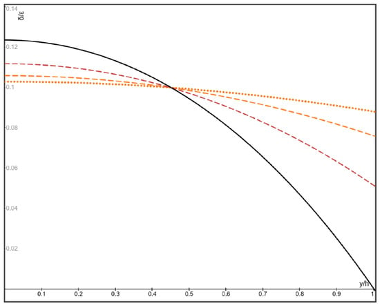
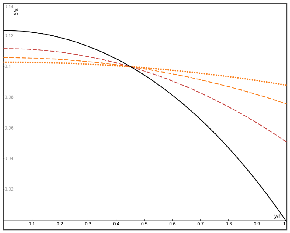
For slowly injected metallic nanoparticles of the density ratio () with β = 0.1, the normalized steady particle volume fraction (δ(y)/ε) over the channel cross-section given by (29) with CL = 4.0 is shown in Figure 8 for four different particle Stokes numbers = 0.03, 0.07, 0.1 and 0.124, respectively, where the = 0.124 is the critical particle Stokes number with CL = 4 at which the particle volume fraction reduces to zero at the channel wall. It is seen from Figure 8 that the particle volume fraction δ(y)/ε is nearly uniform over the cross-section for the particle Stokes number smaller than or equal to 0.03 (shown by the nearly flat dotted curve). With the increasing particle Stokes number, it is seen from Figure 8 that the lateral particle migration toward the centerline leads to non-uniform particle distribution over the cross-section. When the particle Stokes number reaches the critical value 0.124, it is seen from Figure 8 that the particle volume fraction δ(y)/ε (shown by the solid curve) vanishes at the channel wall y = ±h. Similar to the results discussed in Section 5.2 for aerosol heavy particles, it is seen from Figure 8 that the crossover of all curves for different particle Stokes numbers (with δ/ε = β) is identified at nearly the same location .
Figure 8.
The normalized steady particle volume fraction δ(y)/ε over the channel cross-section given by (29) with β = 0.1, and CL = 4, for = 0.03 (dotted curve), 0.07, 0.1 and 0.124 (solid curve), respectively, in order from the lowest to the highest maximum at the midline y = 0.
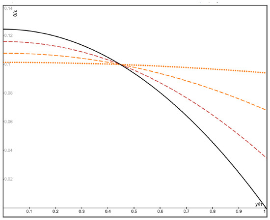
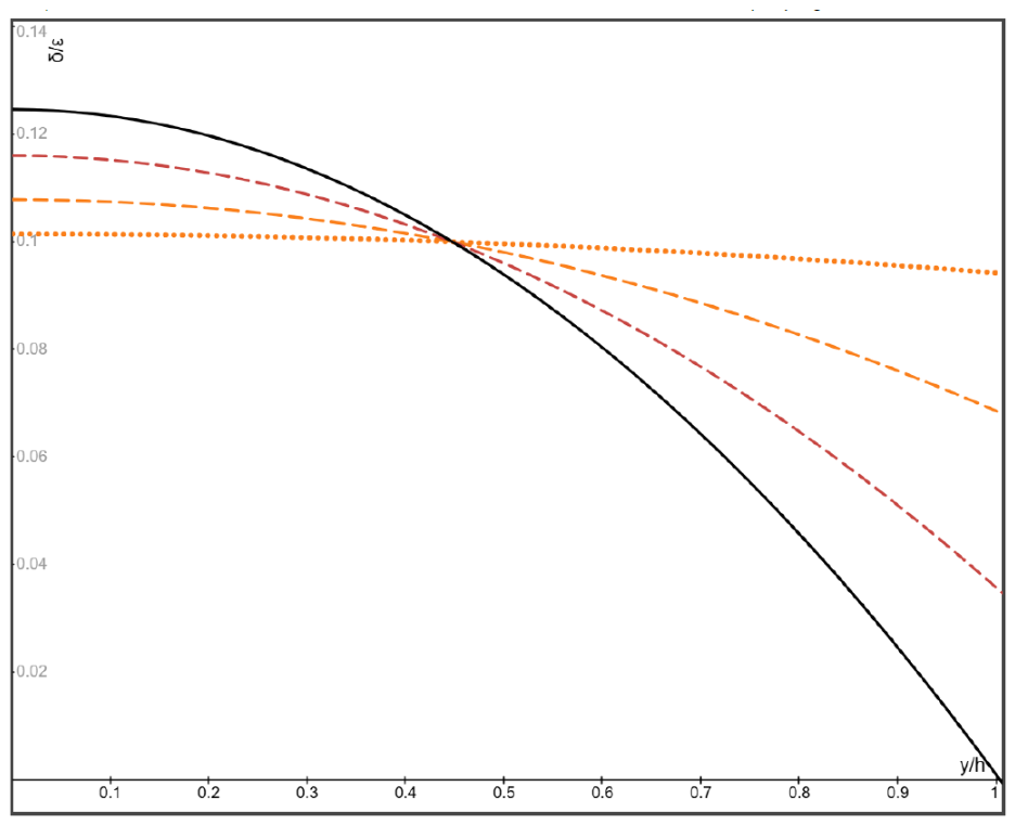
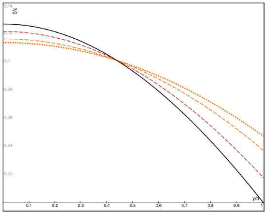
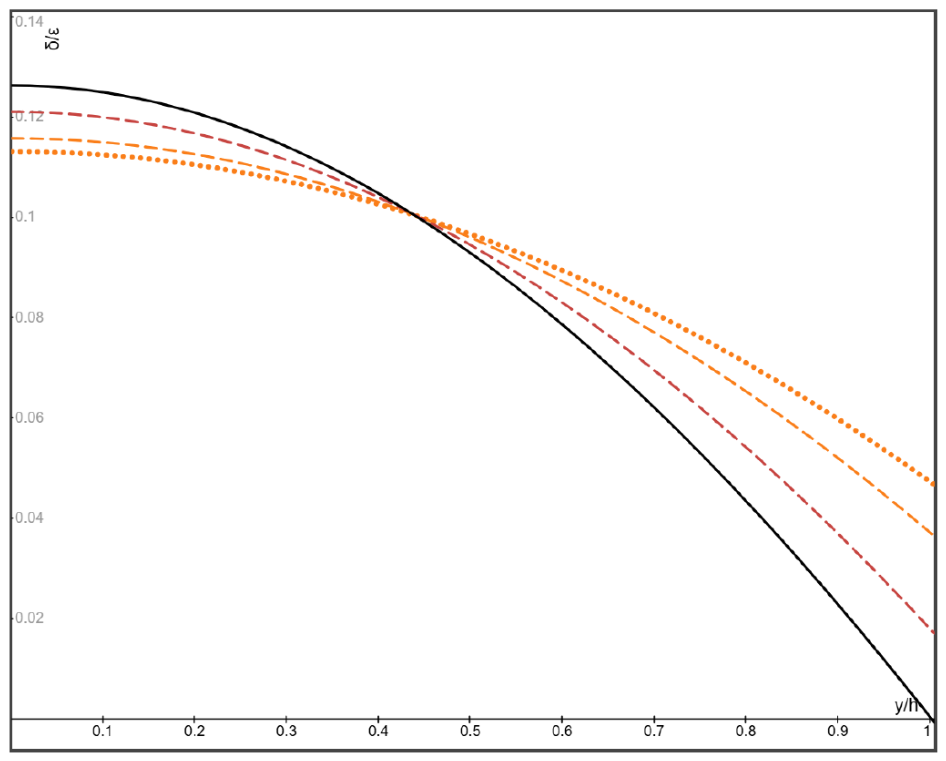
To further illustrate the role of the lift coefficient CL in the steady particle distribution, the normalized particle volume fraction (δ(y)/ε) over the channel cross-section given by (29) with () and β = 0.1 for the particle Stokes number = 0.124 is shown in Figure 9 for four different lift coefficients CL = 0.5, 1, 2 and 4.0, respectively, where = 0.124 is the critical particle Stokes number for β = 0.1 and CL = 0.4. It is seen from Figure 9 that the lateral particle migration-induced non-uniformity of particle distribution increases with the increasing lift coefficient CL, and the crossover of all curves for different lift coefficients (with δ/ε = β) is identified again around the same location at y ≈ ±0.45h.
Figure 9.
The normalized steady particle volume fraction δ(y)/ε over the channel cross-section given by (29) with β = 0.1, and , for CL = 0.5 (dotted curve), 1.0, 2.0, and 4.0 (solid curve), respectively, in order from the lowest to the highest maximum at the midline y = 0.
In a microchannel of relatively larger cross-section and lower flow speed, the Stokes number of nanoparticles can be a few orders of magnitude smaller than 0.1 and therefore not covered by the results shown in Figure 8 and Figure 9 for β = 0.1. In such a case, because the critical particle Stokes number is proportional to √β, it is seen from (31) that the critical particle Stokes number can be a few orders of magnitude smaller than 0.1 when the nanoparticles are injected at a vanishingly low inlet velocity ratio β of the order much lower than 0.1. Therefore, significant lateral particle migration can develop when the particle-to-fluid inlet velocity ratio β is many orders of magnitude lower than the unity, which could lead to quantitatively different but qualitatively similar non-uniform particle distribution over the channel cross-section as those shown in Figure 8 and Figure 9.
Particle migration toward the centerline in a circular pipe flow of a nanofluid was studied by Ding & Wen [16]. It was shown in [16] that the particle migration could be dominated by the hydrodynamic forces for relatively larger nanoparticles (≥100 nm) when the particle Peclet number (defined by the ratio of particle migration due to hydrodynamic forces to that due to Brownian diffusion) is larger than 10. Axisymmetric particle concentration of a nanofluid for several different values of the Peclet number larger than 10 is shown in Figure 4 of [16], which increases monotonically toward the centerline, and the value of particle concentration at the centerline is more than twice of its value at the pipe wall, qualitatively consistent with our results reported here.
Remarkably, the crossover identified in the present analysis is similar to the crossover shown in Figure 4 of [16] for nanoparticles in a pipe flow for different particle Peclet numbers. Since the particle Peclet number of nanoparticles in [16] and the particle Stokes number in the present work both scale with the squared particle radius, the crossover (at a radial distance slightly larger than 0.6 the pipe radius) shown in Figure 4 of [16] for different Peclet numbers is qualitatively similar to the crossover (at ) shown here for different particle Stokes numbers. This noticeable similarity of the crossover identified in the present analysis of a channel plane flow with that of [16] in an axisymmetric pipe flow could be supporting evidence to qualitatively validate the present analysis. It should be stated here that the identified crossover location is approximate when the particle-to-fluid inlet velocity ratio is much smaller than the unity, it becomes an exact result in the limit case when the inlet velocity ratio approaches zero.
5.4. Gas Bubbles Injected Slowly with β = 0.1
As the examples of the Case 2 discussed in Section 4.2 defined by the condition or , let us now discuss the gas bubbles in a liquid [35,36,37,38,39,40]. As stated above, because the shear-induced lift force model adopted in the present analysis does not account for the wall-lift force which could be relevant for particle accumulation near the channel wall, we shall focus on the cases with the condition and therefore the particles laterally move to the centreline rather than to the channel wall.
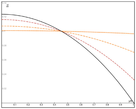
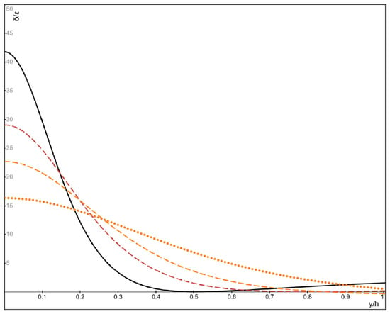
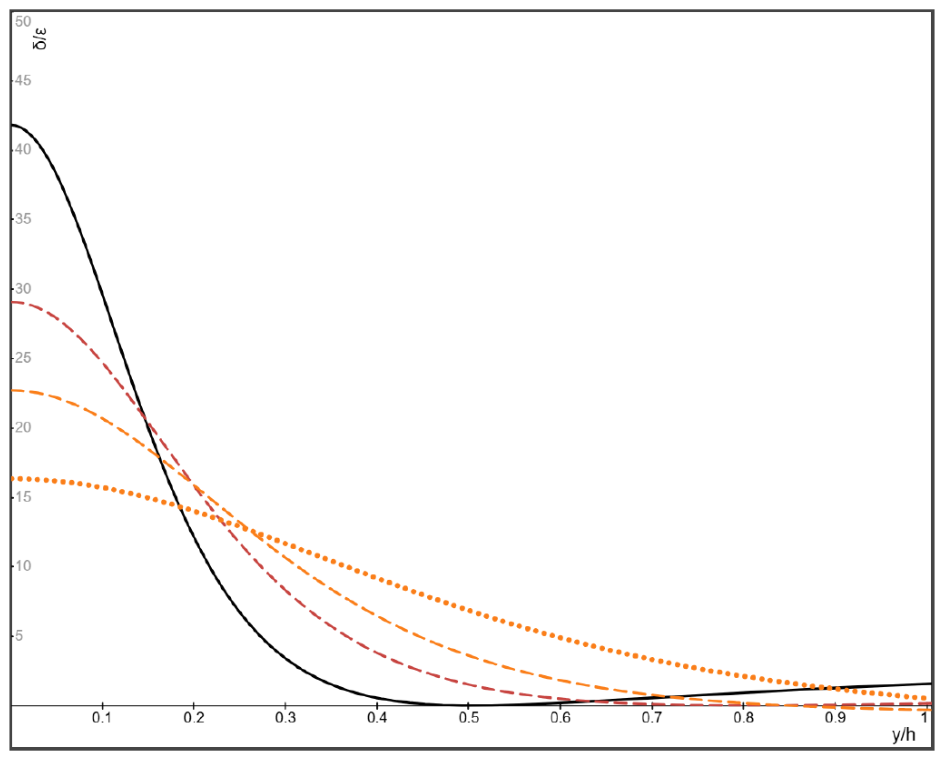
First, let us discuss the case with β = 0.1 (then, ). The normalized bubble volume fraction (δ(y)/ε) over the channel cross-section given by (37) with the particle Stokes number is shown in Figure 10 for four different lift coefficients 0.5, 0.6, 0.7 and 1.0, respectively, where the is the critical bubble Stokes number with β = 0.1 and CL = 1.0 at which the bubble volume fraction reduces to zero at the channel wall. It is verified that the right-hand side of 2nd equation in (39) is more than one order of magnitude smaller than the unity for the four lift coefficients 0.5, 0.6, 0.7 and 1.0, and therefore the condition in (38) is met. It is seen from Figure 10 that the lateral bubble migration toward the midline leads to non-uniform bubble distribution over the cross-section, and the non-uniformity of bubble distribution increases with the increasing positive lift coefficient. In addition, the crossover of the curves for different lift coefficients (with δ/ε = β) is identified again around the same location at y ≈ ±0.45h.
Figure 10.
The normalized steady bubble volume fraction δ(y)/ε over the channel cross-section given by (37) with β = 0.1, approaching zero and , for CL = 0.5 (dotted curve), 0.6, 0.8, and 1.0 (solid curve), respectively, in order from the lowest to the highest maximum at the midline y = 0.
5.5. Gas Bubbles Injected Fast with β = 10
Finally, the normalized steady bubble volume fraction (δ(y)/ε) over the channel cross-section given by (37) with and β = 10 for the bubble Stokes number is shown in Figure 11 for four different lift coefficients CL = −0.1, −0.2, −0.3 and −0.5, respectively, where the is the critical bubble Stokes number at which the bubble volume fraction reduces to zero at the channel wall and some other points. In this case, the condition holds, as discussed in Section 4.2, the bubbles laterally move toward the centerline. It is seen from Figure 11 that the lateral particle migration toward the centerline leads to non-uniform bubble distribution over the cross-section, and the maximum bubble volume fraction at the midline (y = 0) increases with the increasing absolute value of the negative lift coefficient.
Figure 11.
The normalized steady bubble volume fraction δ(y)/ε over the channel cross-section given by (37) with β = 10, approaching zero and , for CL = −0.1 (dotted curve), −0.2, −0.3, and −0.5 (solid curve), respectively, in order from the lowest to the highest maximum at the midline y = 0.
Particularly, some interesting results are shown in Figure 11 for fast injected bubbles (β = 10) with the negative lift coefficient. Unlike the monotonic non-uniform steady particle volume fraction in all previous cases shown in Figure 6, Figure 7, Figure 8, Figure 9 and Figure 10 with β = 0.1 and the positive lift coefficient, the non-monotonic steady particle volume fraction occurs with the lift coefficient CL = −0.5, as shown by the solid curve in Figure 11. In addition, with the particle-to-fluid inlet velocity ratio β = 10 and the lift coefficient , the right-hand side of 2nd equation in (39) is larger than 5/9, and therefore the condition in (38) cannot be met. Consequently, the crossover of different curves for various lift coefficients identified for the previous examples with slowly injected particles and (β = 0.1 and ) does not occur in Figure 11 for the fast injected bubbles with β = 10 and the negative lift coefficient .
It is stated again that the derived analytical expressions are based on the adopted shear-induced lift force model with a positive lift-force coefficient which is different than the lift force models adopted by some authors in the related literature where the lift forces depend on other particle and flow conditions, such as the wall effect, shear gradient, the particle Reynolds number and particle-to-channel size ratio. Therefore, the applicability of the present results to realistic particle-laden suspensions could be qualitative in nature. In addition, to ensure the positivity of the predicted particle volume fraction, the present analysis is limited to finite particle Stokes number not bigger than the critical particle Stokes number, and the present method and derived results break down when the particle Stokes number is bigger than the critical particle Stokes number. Specifically, in all cases discussed in the present analysis, the lateral particle migration toward the midline does not lead to particle accumulation on the channel wall, and therefore the wall-lift force and the induced near-wall particle migration can be less relevant for the present problem. Finally, the present analysis is restricted to the non-neutrally buoyant particles; the derived formulas are not intended to be applied to the neutrally buoyant particle-laden suspensions.
6. Conclusions
The steady particle distribution in particulate microchannel plane flows is studied based on the shear-induced lift force model widely adopted in the literature with the lift force coefficient to be specified. When the particle Stokes number is sufficiently small, the Stokes drag-driven particles quickly match the carrier fluid velocity prior to any meaningful lateral particle migration, and the steady particle volume fraction remains uniform over the channel cross-section and equal to the migration-free particle volume fraction. With increasing particle Stokes number, the lift force drives lateral particle migration toward the midline or the channel wall, depending on the sign of the lift force coefficient and whether the particle inlet velocity is slower or faster than the fluid velocity, which leads to non-uniform particle distribution over the channel cross-section. Our results show
- (1)
- The particle volume fraction exponentially converges to its steady particle distribution with increasing axial distance from the channel entrance. At sufficiently larger distance from the entrance where the particle velocity matches the fluid velocity and the lateral particle migration stops, explicit expressions are derived for the steady particle volume fraction over the channel cross-section along the channel.
- (2)
- When the increasing particle Stokes number reaches a critical value, the particle volume fraction reduces to zero at the channel wall or the midline, depending on the sign of lift force coefficient and whether the particle-to-fluid inlet velocity ratio is smaller or larger than the unity. Explicit formulas are given for the critical particle Stokes number in some typical cases, and the present method and derived formulas break down when the particle Stokes number is bigger than the critical particle Stokes number.
- (3)
- Remarkably, when the lift force coefficient is positive and the particle-to-fluid inlet velocity ratio is at least one order of magnitude smaller than the unity, two specific locations symmetric about the midline, at a distance about 0.45 the half-channel height from the midline, are identified at which the steady particle volume fraction remains nearly equal to its migration-free value, regardless of specific values of the lift force coefficient, the particle-to-fluid density ratio and the particle Stokes number.
- (4)
- The predicted results are compared to some available known data on particulate microchannel flows with qualitative agreement.
The present analysis is based on the condition that the particle inlet velocity at the entrance has the similar profile as the classic velocity distribution of pressure-driven Poiseuille channel flow. The influence of an otherwise inlet velocity profile of the injected particles (for example, the uniform particle inlet velocity distribution) on the steady particle distribution is to be investigated.
Funding
This research received no external funding.
Data Availability Statement
The original contributions presented in this study are included in the article. Further inquiries can be directed to the corresponding author.
Acknowledgments
The free online version of “Desmos” graphing calculator has been used to make the figures presented in this article.
Conflicts of Interest
The author declares no conflicts of interest.
Appendix A. Derivation of Expressions (28) and (29)
It follows from (26) that
Thus, it can be verified that
It follows from (26) and (27) that
Note that
the expression (28) is obtained.
Furthermore, in order to achieve an explicit expression for the steady particle distribution over the channel cross-section after the lateral particle migration settles down, it is noted that for any positive constant c > 0, in the limit when x approaches infinity, we have
Thus, at the limit when x approaches infinity, it is verified from (A3) that
and the expression (29) is verified.
Appendix B. Derivation of Expressions (36) and (37)
It is verified that
Thus, it follows from (27), (34) and (35) that
the expression (36) is obtained.
To achieve an explicit expression for the steady particle distribution over the channel cross-section after the lateral particle migration settles down, it is noted that for any two real constants a and b (not confused with the model coefficients a and b in Equation (5)), we have the indefinite integrals
Thus, when b = −c, where c > 0, at the limit when x approaches infinity, we have
When x tends to infinity, it follows from (A8) and (A10) that
which gives
and the expression (37) is verified.
References
- Segre, G.; Silberberg, A. Behavior of macroscopic rigid spheres in Poiseuille flow. Part 2. Experimental results and interpretation. J. Fluid Mech. 1962, 14, 136–157. [Google Scholar] [CrossRef] [Scilit]
- Hogg, A.J. The inertial migration of non-neutrally buoyant spherical particles in two-dimensional shear flows. J. Fluid Mech. 1994, 272, 285–318. [Google Scholar] [CrossRef] [Scilit]
- Asmolov, E.S. The inertial lift on a spherical particle in a plane Poiseuille flow at large channel Reynolds number. J. Fluid Mech. 1999, 381, 63–87. [Google Scholar] [CrossRef] [Scilit]
- Anand, P.; Subramanian, G. Inertial migration of a neutrally buoyant spheroid in plane Poiseuille flow. J. Fluid Mech. 2023, 974, A39. [Google Scholar] [CrossRef] [Scilit]
- Ruan, Y.; Xiao, Z. On the shear-induced lift in two-way coupled turbulent channel flow laden with heavy particles. J. Fluid Mech. 2024, 984, A24. [Google Scholar] [CrossRef] [Scilit]
- Phillips, R.J.; Armstrong, R.C.; Brown, R.A.; Graham, A.L.; Abbott, J.R. A constitutive equation for concentrated suspensions that accounts for shear-induced particle migration. Phys. Fluids 1992, A4, 30–40. [Google Scholar] [CrossRef] [Scilit]
- McLaughlin, J.B. The lift on a small sphere in wall-bounded linear shear flows. J. Fluid Mech. 1993, 246, 249–265. [Google Scholar] [CrossRef] [Scilit]
- Osiptsov, A.A.; Asmolov, E.S. Asymptotic model of the inertial migration of particles in a dilute suspension flow through the entry region of a channel. Phys. Fluids 2008, 20, 123301. [Google Scholar] [CrossRef] [Scilit]
- Di Carlo, D. Inertial microfluidics. Lab Chip 2009, 9, 3038–3046. [Google Scholar] [CrossRef] [Scilit]
- Zhou, J.; Papautsky, I. Fundamentals of inertial focusing in microchannels. Lab Chip 2013, 13, 1121–1132. [Google Scholar] [CrossRef] [Scilit]
- Zhang, J.; Yan, S.; Yuan, D.; Alici, G.; Nguyen, N.T.; Warkianic, M.E.; Li, W. Fundamentals and applications of inertial microfluidics: A review. Lab Chip 2016, 16, 10–34. [Google Scholar] [CrossRef] [Scilit]
- Tanriverdi, S.; Cruz, J.; Habibi, S.; Amini, K.; Costa, M.; Lundell, F.; Mårtensson, G.; Brandt, L.; Tammisola, O.; Russom, A. Elasto-inertial focusing and particle migration in high-aspect ratio microchannels for high-throughput separation. Microsyst. Nanoeng. 2024, 10, 87. [Google Scholar] [CrossRef] [Scilit]
- Akhatov, I.; Hoey, J.; Swenson, O.; Schulz, D. Aerosol focusing in micro-capillaries: Theory and experiment. J. Aerosol Sci. 2008, 39, 691–709. [Google Scholar] [CrossRef] [Scilit]
- Bhattacharya, S.; Lutfurakhmanov, A.; Hoey, J.M.; Swenson, O.F.; Mahmud, Z.; Akhatov, I.S. Aerosol flow through a converging-diverging micro-nozzle. Nonlinear Eng. 2013, 2, 103–112. [Google Scholar] [CrossRef] [Scilit]
- Qin, Y.; Fan, L.-L.; Zhao, L. Efficient focusing of aerosol particles in the microchannel under reverse external force: A numerical simulation study. Micromachines 2023, 14, 554. [Google Scholar] [CrossRef] [Scilit]
- Ding, Y.L.; Wen, D.S. Particle migration in a flow of nanoparticle suspensions. Powder Tech 2005, 149, 84–92. [Google Scholar] [CrossRef] [Scilit]
- Sharaf, O.Z.; Al-Khateeb, A.N.; Kyritsis, D.C.; Abu-Nada, E. Numerical investigation of nanofluid particle migration and convective heat transfer in microchannels using an Eulerian–Lagrangian approach. J. Fluid Mech. 2019, 878, 62–97. [Google Scholar] [CrossRef] [Scilit]
- Elbadawy, I.; Alali, F.; Derakhshandeh, J.F.; Dinc, A.; Abouslela, M.; Al-Kouz, W. Effect of Al2O3, SiO2, and ZnO nanoparticle concentration mixed with EG-Water on hear transfer characteristics through a microchannel. Processes 2023, 11, 2015. [Google Scholar] [CrossRef] [Scilit]
- Xu, W.; Li, W.; Wang, J.; Song, Y.; Wu, B.; Wen, J.; Li, K.; Li, B. Numerical simulation of gas-liquid two-phase flow CFD-PBM model in a micro-nanobubble generator. Minerals 2022, 12, 1270. [Google Scholar] [CrossRef] [Scilit]
- Garcia-Magariño, A.; Lopez-Gavilan, P.; Sor, S.; Terroba, F. Micro/bubble drag reduction focused on new applications. J. Mar. Sci. Eng. 2023, 11, 1315. [Google Scholar] [CrossRef] [Scilit]
- Morris, J.; Brady, J. Pressure-driven flow of a suspension: Buoyancy effects. Int. J. Multiph. Flow 1998, 24, 105–130. [Google Scholar] [CrossRef] [Scilit]
- Norman, J.T.; Nayak, H.V.; Bonnecaze, R.T. Migration of buoyant particles in low-Reynolds-number pressure-driven flows. J. Fluid Mech. 2005, 523, 1–35. [Google Scholar] [CrossRef] [Scilit]
- Ramachandran, A.; Leighton, D.T. The effect of gravity on the meniscus accumulation phenomenon in a tube. J. Rheol. 2007, 51, 1073–1098. [Google Scholar] [CrossRef] [Scilit]
- Ru, C.Q. An extended Rayleigh equation for the uniform inviscid plane flow with gas bubble crossflow. Processes 2025, 13, 3665. [Google Scholar] [CrossRef] [Scilit]
- Ru, C.Q. Stability of plane parallel flow revisited for particle—Fluid suspensions. J. Appl. Mech. 2024, 91, 111005. [Google Scholar] [CrossRef] [Scilit]
- Ru, C.Q. On Kelvin-Helmholtz instability of particulate two-fluid flow. Acta Mech. Sin. 2025, 41, 324143. [Google Scholar] [CrossRef] [Scilit]
- Saffman, P.G. On the stability of laminar flow of a dusty gas. J. Fluid Mech. 1962, 13, 120–128. [Google Scholar] [CrossRef] [Scilit]
- Michael, D.H. Kelvin-Helmholtz instability of a dusty gas. Math. Proc. Camb. Philos. Soc. 1965, 61, 569–571. [Google Scholar] [CrossRef] [Scilit]
- Loth, E.; Dorgan, A.J. An equation of motion for particles of finite Reynolds number and size. Environ. Fluid Mech. 2009, 9, 187–206. [Google Scholar] [CrossRef] [Scilit]
- Gao, W.; Shi, P.; Parsani, M.; Costa, P. On the relevance of lift force modeling in turbulent wall flows with small inertial particles. J. Fluid Mech. 2024, 988, A47. [Google Scholar] [CrossRef] [Scilit]
- Saffman, P.G. The lift on a small sphere in a slow shear flow. J. Fluid Mech. 1965, 22, 385–400. [Google Scholar] [CrossRef] [Scilit]
- Auton, T.R. The lift force on a spherical body in a rotational flow. J. Fluid Mech. 1987, 183, 199–218. [Google Scholar] [CrossRef] [Scilit]
- Li, H.; Ku, X.; Lin, J. Eulerian–Lagrangian simulation of inertial migration of particles in circular Couette flow. Phys. Fluids 2020, 32, 073308. [Google Scholar] [CrossRef] [Scilit]
- Bellache, H.; Chapelle, P.; Kroll-Rabotin, J.-S. Particles in homogeneous isotropic turbulence: Clustering and relative influence of the forces exerted on particles. Fluids 2025, 10, 201. [Google Scholar] [CrossRef] [Scilit]
- Magnaudet, J.; Eames, I. The motion of high-Reynolds-Number bubbles. Annu. Rev. Fluid Mech. 2000, 32, 659–708. [Google Scholar] [CrossRef] [Scilit]
- Legendre, D.; Zenit, R. Gas bubble dynamics. Rev. Mod. Phys. 2025, 97, 025001. [Google Scholar] [CrossRef] [Scilit]
- Adoua, R.; Legendre, D.; Magnaudet, J. Reversal of the lift force on an oblate bubble in a weakly viscous linear shear flow. J. Fluid Mech. 2009, 628, 23–41. [Google Scholar] [CrossRef] [Scilit]
- Hayashi, K.; Lucas, D.; Legendre, D.; Tomiyama, A. Critical diameter for lift reversal of bubbles in linear shear flows. Multiph. Sci. Technol. 2021, 33, 69–85. [Google Scholar] [CrossRef] [Scilit]
- Hidman, N.; Ström, H.; Sasic, S.; Sardina, G. The lift force on deformable and freely moving bubbles in linear shear flows. J. Fluid Mech. 2022, 952, A34. [Google Scholar] [CrossRef] [Scilit]
- Zand, M.K.; Puttinger, S.; Saeedipour, M. A new approach to unravel the lift force phenomenon of a single bubble rising in straight and sheared liquids. Int. J. Multiph. Flow 2025, 188, 105219. [Google Scholar] [CrossRef] [Scilit]
Disclaimer/Publisher’s Note: The statements, opinions and data contained in all publications are solely those of the individual author(s) and contributor(s) and not of MDPI and/or the editor(s). MDPI and/or the editor(s) disclaim responsibility for any injury to people or property resulting from any ideas, methods, instructions or products referred to in the content. |
© 2026 by the author. Licensee MDPI, Basel, Switzerland. This article is an open access article distributed under the terms and conditions of the Creative Commons Attribution (CC BY) license.