


Abstract
Low-temperature CO2 fracturing generates obvious thermal tensile disturbance via reservoir–fluid temperature difference, which is an efficient stimulation technology for hot dry rock (HDR). In this work, a two-dimensional plane-strain thermo-hydro-mechanical-damage (THMD) coupling numerical model considering granite mechanical heterogeneity is established, and seven single-variable simulation cases are designed to quantitatively analyze the joint effects of fluid type, reservoir temperature, injection parameters, and in situ stress on HDR damage, temperature-pore pressure field, and system energy evolution. The results show that the damaged area induced by CO2 injection is five times larger than that of water under identical baseline conditions. Raising reservoir temperature or injection pressure significantly strengthens thermo-seepage coupling effects, with the maximum damaged area ratio increased by over 220%. Higher CO2 injection pressure and lower injection temperature weaken thermal stress and restrain fracture propagation; an anisotropic stress field only produces a single main fracture without complex branch networks. Energy analysis indicates injection pressure dominates the accumulation of HDR strain potential energy, and the potential energy under high injection pressure can reach more than 11 times the baseline value. This study quantitatively analyzes the individual influences of fluid type, reservoir temperature, injection temperature, injection pressure, and in situ stress anisotropy on HDR damage evolution, and discusses their combined effects.
1. Introduction
Clean and renewable deep geothermal resources are a crucial support for optimizing energy structures and achieving low-carbon transformation [1]. Hot dry rock (HDR) reserves are vast, with high thermal storage capacity and wide distribution, making them the core reservoirs for deep geothermal development [2,3]. However, due to their dense HDR structure and low porosity and permeability, natural formation alone cannot establish effective fluid circulation pathways [4], necessitating artificial fracturing to enhance reservoir permeability. The effectiveness of such stimulation directly determines the development potential of geothermal resources [5,6]. Therefore, studying the fracture initiation mechanisms in high-temperature HDR is fundamental to improving theoretical understanding and field practices for reservoir stimulation.
Conventional hydraulic fracturing technology is mature and widely used; however, water-based fracturing fluids have high viscosity and poor diffusivity, resulting in limited fracture propagation capability within high-temperature, tight HDR formations and an inability to generate complex fracture networks, leading to limited stimulation outcomes [7]. As an emerging reservoir stimulation technique, CO2 fracturing offers advantages such as low viscosity, high fluidity, and strong heat transfer properties, making it better suited for stimulating high-temperature, tight rocks [8]. The significant temperature differences between injected low-temperature CO2 and the hot reservoir can induce intense thermal shock, generating additional thermal tensile stresses within the surrounding rock [9]. These stresses interact synergistically with fluid pressure and in situ stress, forming multi-field coupling effects that effectively reduce rock fracture toughness and promote multi-directional crack propagation [10,11]. Thus, revealing the coupled mechanisms of multiple parameters in CO2 fracturing is a key prerequisite for efficient HDR stimulation.
Currently, Li et al. [12] and Xu et al. [13] have preliminarily revealed the degradation mechanisms of rock mechanical properties under thermal effects. Additionally, focusing on rock damage responses under pure thermal shock conditions, Hu et al. [14] conducted rapid liquid nitrogen quenching tests at temperatures ranging from 25 to 850 °C. The results showed that uniaxial compressive strength continuously decreased with increasing thermal treatment temperature, with the most intense thermal damage evolution occurring between 550 and 850 °C. Based on energy storage efficiency, Xiong et al. [15] compared the evolution patterns of granite mechanical properties under different cooling methods, confirming that rapid cooling significantly reduces rock tensile strength and fracture toughness, quantitatively revealing the intensifying effect of abrupt temperature drops on rock damage. However, these studies considered only thermal loading in isolation, without incorporating the coupled effects of fluid pressure commonly encountered in fracturing operations. Experimental data indicate that achieving effective reservoir permeability enhancement through pure thermal shock requires a substantial temperature difference of 500~600 °C, which far exceeds the actual reservoir temperatures of dry hot rocks in field conditions [16]. This implies that efficient fracturing in dry hot rock reservoirs must rely on the synergistic coupling of fluid pressure and thermal stress [17,18]. Research on the coupled response characteristics of hydraulic fracturing in high-temperature rock has been progressively advancing through experimental and numerical approaches. Dai et al. [19] conducted high-temperature true-triaxial cyclic fracturing experiments combined with a thermo-hydro-mechanical-damage (THMD) coupled numerical model, demonstrating that cyclic fracturing can reduce the breakdown pressure of dry hot rock and induce the formation of complex fracture networks. The sample breakdown pressure decreased by 1.6~5.5 MPa compared to conventional fracturing, while the proportion of shear fractures increased by 4.4~13.1%. Liu et al. [20] found that longitudinal wave velocity and tensile strength of granite exhibit logarithmic decay under cyclic thermal loading, with liquid nitrogen-cooled samples showing a 15~20% greater reduction in wave velocity than water-cooled samples at 650 °C. Li et al. [21] performed liquid nitrogen fracturing experiments, showing that the low viscosity of liquid nitrogen can reduce the initiation pressure by 30% compared to conventional hydraulic fracturing, and additional thermal stress further lowers the initiation threshold by 20%. Although existing experiments have yielded a series of macroscopic evolution laws, limitations in monitoring techniques make it difficult to achieve real-time, quantitative characterization of the spatiotemporal evolution of multiple physical fields throughout the entire fracturing process [22]. A systematic understanding of the dynamic coupling fracturing mechanism under the joint influence of thermal stress, fluid pressure, and in situ stress remains lacking.
Compared to experimental methods, numerical simulation can effectively reveal the mesoscopic mechanisms of crack initiation, propagation, and multi-field evolution [23], and has been widely applied in unconventional reservoir fracturing studies such as shale fracturing [24], conglomerate fracturing [25], and re-fracturing [26]. However, existing numerical studies on enhanced geothermal system (EGS) fracturing still have significant limitations. Most models focus solely on the single propagation behavior of conventional hydraulic fractures, while research on the thermo-hydro-mechanical coupled damage evolution induced by low-temperature CO2 injection remains insufficient. CO2 fluid exhibits low viscosity, high compressibility, and strong cooling properties [27,28], and the initial formation temperature, along with the temperature and pressure conditions during CO2 injection, jointly control the spatial distribution of thermal stresses in rock, ultimately altering the development pattern of the fracture network [29]. Existing numerical and quantitative experimental results have revealed differences in reservoir modification across four dimensions: crack initiation characteristics, pore evolution, heat extraction efficiency, and fracture morphology. Zhang et al. [30] demonstrated that under identical storage temperature and in situ stress conditions, the breakdown pressure for CO2 fracturing is 45% lower than that of water-based hydraulic fracturing. Aliabadian et al. [31] conducted a parametric analysis on injection flow rates; when the CO2 injection rate increased from 5 kg/s to 10 kg/s, the initiation time decreased from 5.19 min to 3.16 min, but higher flow rates hindered the development of extensive interconnected fracture networks. Li et al. [32] found after a 96 h immersion test with CO2 that the overall porosity of granite decreased by up to 25%, micro-pore proportion increased, and the complexity of rock porosity significantly improved. Zhang et al. [33] indicated that under high-injection-rate conditions with large fractures, a mixed fluid ratio of water: CO2 = 6:4 achieved optimal heat transfer performance, reaching a peak output thermal power of 150 W and a maximum temperature drop of 78 °C between inlet and outlet. Feng et al. [34] showed that using an injection configuration with upper-layer injection and lower-layer production increased total cumulative heat extraction by 36%, with system stable heat production lasting up to 50 years. Li et al. [35] concluded through simulation that under high in situ stress conditions with a horizontal stress anisotropy of 12.3 MPa, staged fracturing tends to generate parallel hydraulic fractures, and only when the horizontal stress anisotropy decreases to 0.3 MPa do cracks exhibit noticeable deflection. Despite these prior studies, the coupled mechanism by which in situ stress anisotropy controls fracture propagation direction and fracture network complexity—especially when additional thermal stresses are introduced by low-temperature fluids—still lacks clear conclusions.
To address the aforementioned research limitations, this work constructs a fully coupled thermo-hydro-mechanical-damage numerical framework with Weibull heterogeneous rock parameters. Seven groups of transient simulation cases with single-variable control are carried out to quantitatively compare the differences in damage morphology, temperature and pore pressure distribution, and energy evolution between water and CO2 fracturing. The influences of reservoir temperature, injection temperature, injection pressure, and horizontal stress anisotropy are systematically discussed. The research conclusions can supply a theoretical reference for HDR geothermal reservoir stimulation design. Compared with previous THMD models, the present model incorporates dynamic CO2 properties from NIST REFPROP instead of constant-property assumptions, a Weibull random field for elastic modulus and tensile strength instead of a homogeneous matrix, a water–CO2 comparison under identical injection pressure rather than identical flow rate, and a unified analysis of damage, temperature, pore pressure, and energy evolution.
2. Methodology
2.1. Physical Model
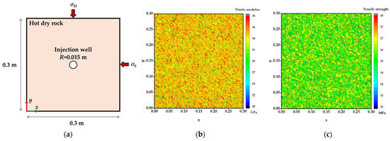
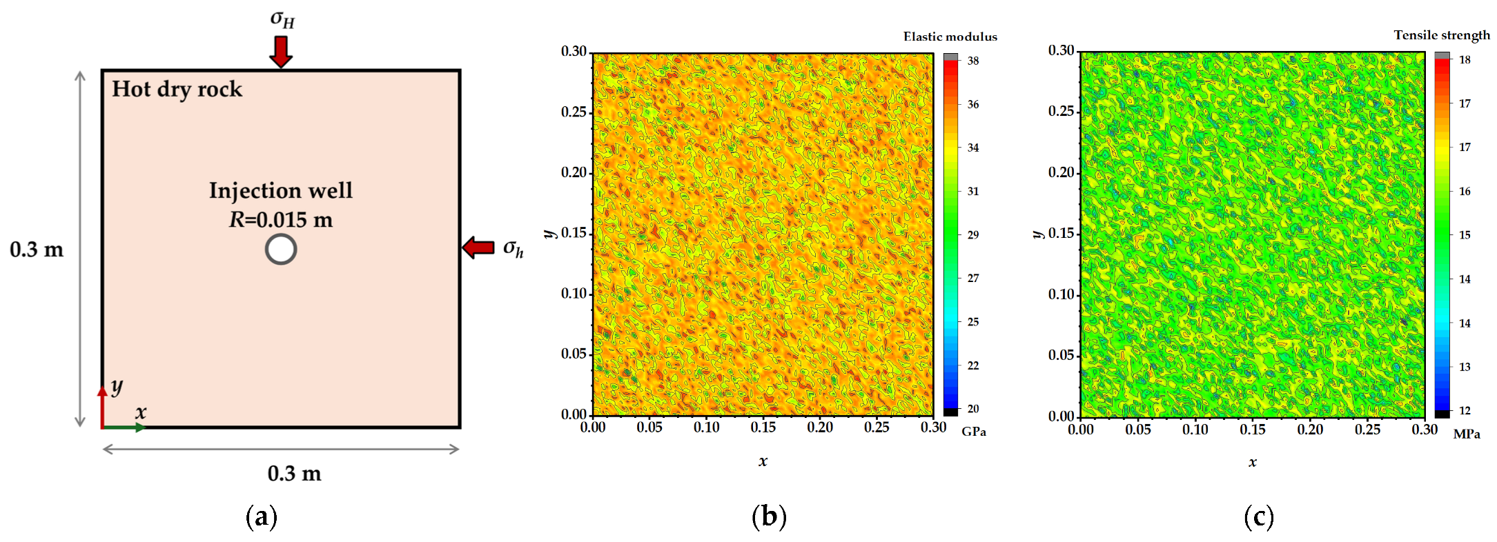
This study develops a two-dimensional plane strain numerical model for coupled THMD processes, comparing the multi-field coupling evolution and fracturing damage patterns in HDR reservoirs under low-temperature injection of water and CO2. The physical model is shown in Figure 1. The computational domain is a square region with side length 0.3 m, with a circular injection wellbore of radius 0.015 m located at the center. The origin of the Cartesian coordinate system is placed at the lower-left corner of the model, with the x-axis extending horizontally and the y-axis vertically. On the outer boundaries, triaxial equivalent horizontal in situ stresses are applied: maximum horizontal principal stress σH on the top and bottom boundaries, and minimum horizontal principal stress σh on the left and right boundaries. Additionally, roller supports are introduced on the external boundaries to eliminate overall rigid body displacements. The HDR mass matrix exhibits good continuity, with only the elastic modulus and tensile strength following a Weibull spatial random distribution, while all other thermal and seepage properties are isotropic and constant throughout the domain. The Weibull homogeneity index is m = 5. The scale parameters are determined from the mean elastic modulus (37 GPa) and mean tensile strength (15 MPa). The spatial distributions of elastic modulus and tensile strength are shown in Figure 1b and c, respectively.
Figure 1.
(a) Schematic of a two-dimensional physical model for low-temperature fluid fracturing of HDR. (b) Weibull random field of elastic modulus. (c) Weibull random field of tensile strength.
This simplification isolates the effect of mechanical heterogeneity and keeps the transient THMD simulation computationally tractable. Spatial heterogeneity in thermal conductivity, permeability, and Biot coefficient may locally alter the thermal stress distribution and fracture path tortuosity, but the dominant thermal-shock mechanism is controlled by the reservoir–fluid temperature difference and is not expected to change qualitatively. The main assumptions of the model are as follows:
- The HDR matrix is continuous, with only mechanical parameters following a Weibull random distribution, while other physical properties are isotropic.
- A plane-strain condition is adopted, representing a horizontal cross-section of the wellbore where fracturing is primarily controlled by horizontal principal stresses; the vertical stress component and out-of-plane fracture propagation are neglected.
- Prior to fluid injection, the initial temperature of the entire computational domain is uniform.
- On the inner wall of the wellbore, both fluid injection pressure and fluid–solid convective heat transfer boundary conditions are coupled.
- The effect of gravity on this horizontal cross-sectional model is neglected.
The basic physical and mechanical properties of the HDR matrix are shown in Table 1. The elastic modulus and tensile strength of the HDR mass are characterized by a Weibull random field to represent spatial heterogeneity. For the liquid phase medium, temperature-dependent liquid water from the COMSOL 6.3 material library is selected. The properties of CO2 are significantly influenced by coupled temperature and pressure effects; using constant properties would lead to considerable computational errors. Therefore, this study retrieves data for CO2 density, dynamic viscosity, specific heat capacity at constant pressure, and thermal conductivity from the NIST REFPROP 10.0 database within the temperature range of 17~227 °C and pressure range of 0.1~40 MPa, enabling dynamic interpolation and updating of material properties based on local temperature and pressure in each element, thus ensuring accuracy in multi-field coupled simulations. Other HDR properties are assigned fixed values.
Table 1.
Basic physical and mechanical parameters of HDR.
The CO2 properties are updated from NIST REFPROP based on local temperature and pressure, so the property variations across the liquid, supercritical, and gaseous states are implicitly included. However, the phase-transition process itself (e.g., latent heat and phase-interface dynamics) and local density fluctuations during rapid depressurization inside expanding fractures are not explicitly modeled, because the present continuum-based plane-strain framework cannot resolve the sub-grid scale of these effects. Under the injection conditions considered in this study (20~60 °C, 25~35 MPa), CO2 remains in the supercritical or near-critical state, so the influence of phase transition on the fluid driving energy is expected to be limited. A more detailed analysis of transcritical injection and rapid depressurization will require a dedicated two-phase or compositional solver.
This study designs seven numerical cases to systematically analyze the effects of reservoir temperature, injection temperature, injection pressure, and horizontal in situ stress on fluid seepage and heat transfer responses. The detailed parameters for each simulation Case are shown in Table 2. Case 1 uses pure water as the injected fluid as a control case; Cases 2~7 all employ CO2 as the injection medium, with single-variable changes applied respectively to the initial reservoir temperature, CO2 injection temperature, injection pressure, and maximum/minimum horizontal principal stresses, while keeping all other parameters constant, thereby enabling comparison of the influence mechanisms of each factor. All cases are designed with a single-variable control strategy; thus, the results mainly reflect the influence of each individual parameter.
Table 2.
Design of the seven single-variable simulation cases.
2.2. Governing Equations
Geothermal HDR hydraulic fracturing is a multi-physical coupled process involving matrix deformation, fracturing fluid flow, and heat transfer between the injected fluid and high-temperature HDR. To accurately describe the initiation and propagation behavior of fractures when low-temperature CO2 is injected into HDR, this study establishes a thermo-hydro-mechanical-damage coupled model based on micromechanical damage mechanics, elastic thermodynamics, and Biot’s poroelasticity theory. Considering the effects of pore fluid pressure and temperature changes on HDR deformation, the static equilibrium equation for a linear elastic body can be expressed as [36]:
where is the shear modulus (Pa), . is Poisson’s ratio. is the elastic modulus (Pa). and are the components of body force and displacement in the i-direction, respectively, . is the pore water pressure term (seepage force), is the Biot coefficient; is the thermal stress term, is the matrix thermal expansion coefficient (1/°C), is the drained bulk modulus (Pa), .
The governing equation for the seepage field considering mechanical stress and temperature effects is [37]:
where is the volumetric strain. is the permeability of the continuous medium (m2). is the fluid dynamic viscosity (Pa·s). is the fluid density (kg/m3). is the gravitational acceleration (m/s2), and is the vertical coordinate (m). The coefficients , , and represent the contributions of volumetric strain, temperature, and pore pressure changes to the seepage field, respectively.
The temperature field control equation considering thermal convection and mechanical stress is [38]:
where , , and are the thermal conductivities of the solid matrix and fluid, respectively (W/(m·K)); is the reference temperature under zero-stress conditions (K); is the heat capacity of the fluid-saturated porous medium (J/(m3·K); and is the porosity.
Equations (1)–(3) constitute a coupled nonlinear system of governing equations for the thermo-elastic response of saturated porous media, comprehensively accounting for heat and mass transfer in thermodynamics as well as the responses of individual components under mechanical stress and temperature.
2.3. Failure Criteria
Tensile or shear damage occurs when the HDR stress state meets the maximum tensile stress criterion () or the Mohr–Coulomb criterion (), respectively. The expressions for and are given in [39]:
where is the uniaxial tensile strength of HDR (Pa); is the uniaxial compressive strength of HDR (Pa); and is the internal friction angle of HDR (°). Dry hot HDR reservoirs are typically composed of granite, with an internal friction angle ranging from 45 to 60°.
In the present model, tensile damage dominates in the cooling-induced region around the wellbore, while shear damage may occur in compressive stress concentration zones ahead of the fracture tip; mixed-mode transition and temperature-dependent fracture toughness are not explicitly considered.
2.4. Damage Evolution
An elastic–brittle damage constitutive model is adopted to describe the mechanical degradation behavior of HDR. When the stress state of an element satisfies the maximum tensile stress criterion (), tensile damage occurs in the element. The relationship between the damage variable and the equivalent tensile strain is defined as [40]:
where is the residual tensile strength coefficient, and are the uniaxial tensile strength and residual tensile strength of the HDR, respectively; is the tensile strain corresponding to the elastic limit; is the ultimate tensile strain, and is the ultimate strain coefficient (typically taken as 3~5).
When the stress state of an element satisfies the Mohr-Coulomb criterion (), shear damage occurs in the element. The relationship between the damage variable D and the equivalent compressive strain ε is defined as [41]:
where is the shear damage initiation threshold strain. The damage variable takes values between 0 and 1: indicates that the element has not yet experienced any damage; indicates partial damage, with the element still retaining residual load-carrying capacity; indicates complete damage, with the element losing all load-carrying ability. In addition, when D = 1, the element is treated as fully failed but is retained in the computational domain to avoid stiffness singularity. The elastic modulus is reduced to a residual value with a lower bound . The permeability reaches its maximum value . The thermal conductivity decreases to . Poisson’s ratio, specific heat capacity, and density are assumed to remain unchanged.
The present model uses constant residual parameters for tensile strength and fracture toughness. If such temperature-dependent degradation were included, the damage initiation threshold would be reached earlier, and the residual load-carrying capacity would be lower, leading to a higher damage accumulation rate. In addition, a lower fracture toughness would reduce the energy required for crack propagation and lower the branching threshold, producing a more complex fracture network. Therefore, the present results can be regarded as a conservative estimate of the damage extent and fracture complexity under high-temperature conditions.
2.5. Grid, Time Independence, and Model Validation
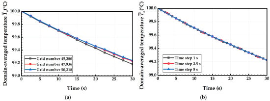
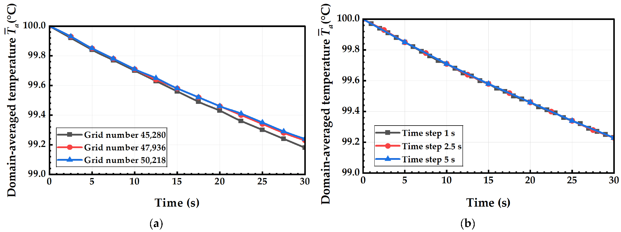
To reduce computational deviation caused by numerical discretization, this study conducts grid independence and time step independence convergence verification based on the average rock mass temperature under Case 1. Three mesh configurations with element counts of 45,280, 47,936, and 50,218 are used, and comparative simulations are performed with time steps of 1 s, 2.5 s, and 5 s, respectively. The damaged area ratio is defined as Rd = Ad/A0, where Ad is the total area of elements with damage variable D > 0, and A0 is the total area of the computational domain. As shown in Figure 2, the overall temperature evolution curves are highly consistent when using finer meshes or smaller time steps. At the end of the simulation, the relative difference in average rock mass temperature between the coarsest and finest meshes is only 0.2%, while differences associated with different time steps are even smaller. Considering both numerical accuracy and computational efficiency, a mesh of 47,936 elements and a time step of 2.5 s are selected as the unified calculation parameters for all subsequent cases.
Figure 2.
(a) Grid, and (b) time step independence validation based on domain-averaged temperature evolution.
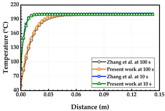
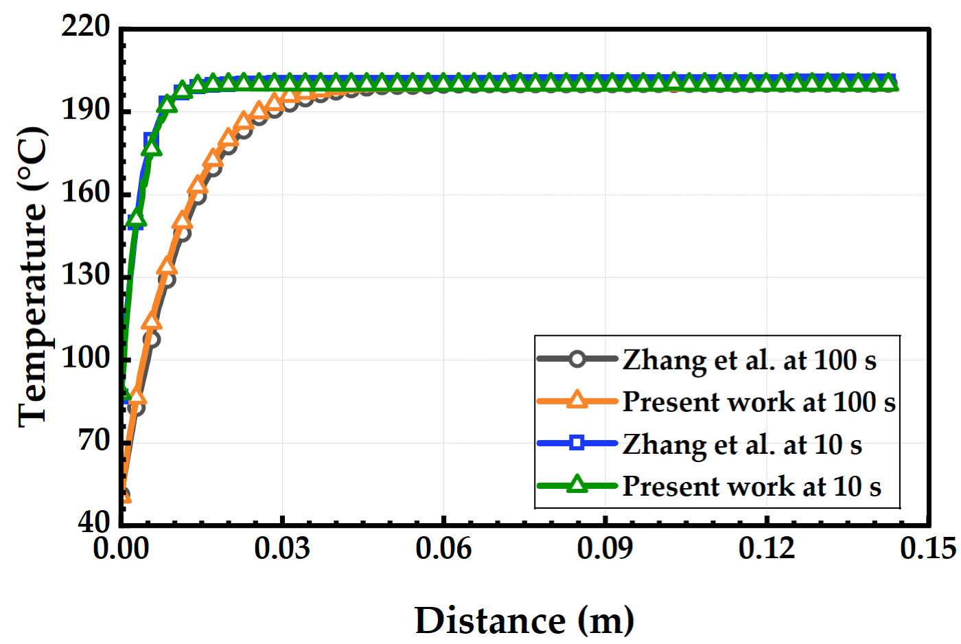
To verify the accuracy of the numerical model, the classical case study by Zhang et al. [36] was calculated. The geometric model consisted of a 0.3 m × 0.3 m square computational domain with a circular wellbore of 0.015 m diameter located at the center. The fluid injection temperature was set to 20 °C, and the convective heat transfer coefficient between the granite and the fluid was taken as 2000 W/(m2·K). The radially resolved temperature field obtained from this study was compared with the benchmark results from the literature, as shown in Figure 3. The results indicate that the simulated temperature gradient evolution closely matches the reference data, with a maximum relative deviation of only 6.78%. The minor discrepancies are mainly attributed to grid discretization accuracy near the wellbore wall and slight differences in thermal property parameter values. Therefore, the heat transfer solution module of the two-dimensional plane strain model developed in this study is accurate and reliable, providing solid support for subsequent analysis of thermal stress evolution.
Figure 3.
Comparison of radial temperature distribution between present simulation and benchmark data [36] at 10 s and 100 s.
3. Results and Discussion
3.1. Spatiotemporal Evolution of HDR Damage Under Different Injection Conditions
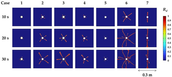
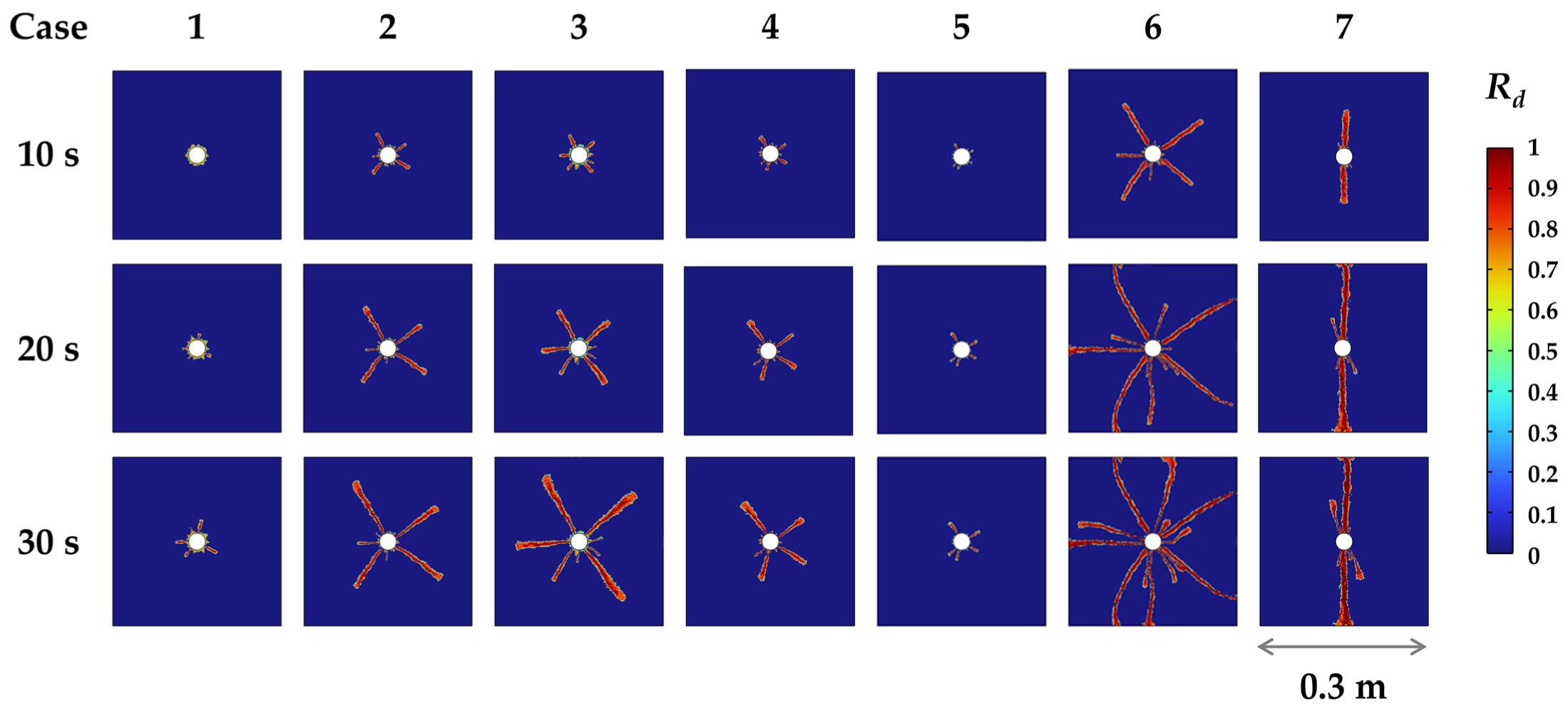
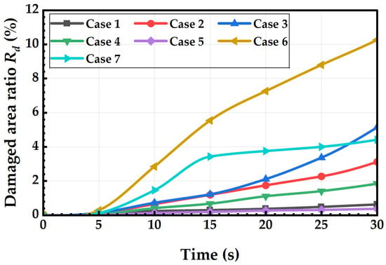
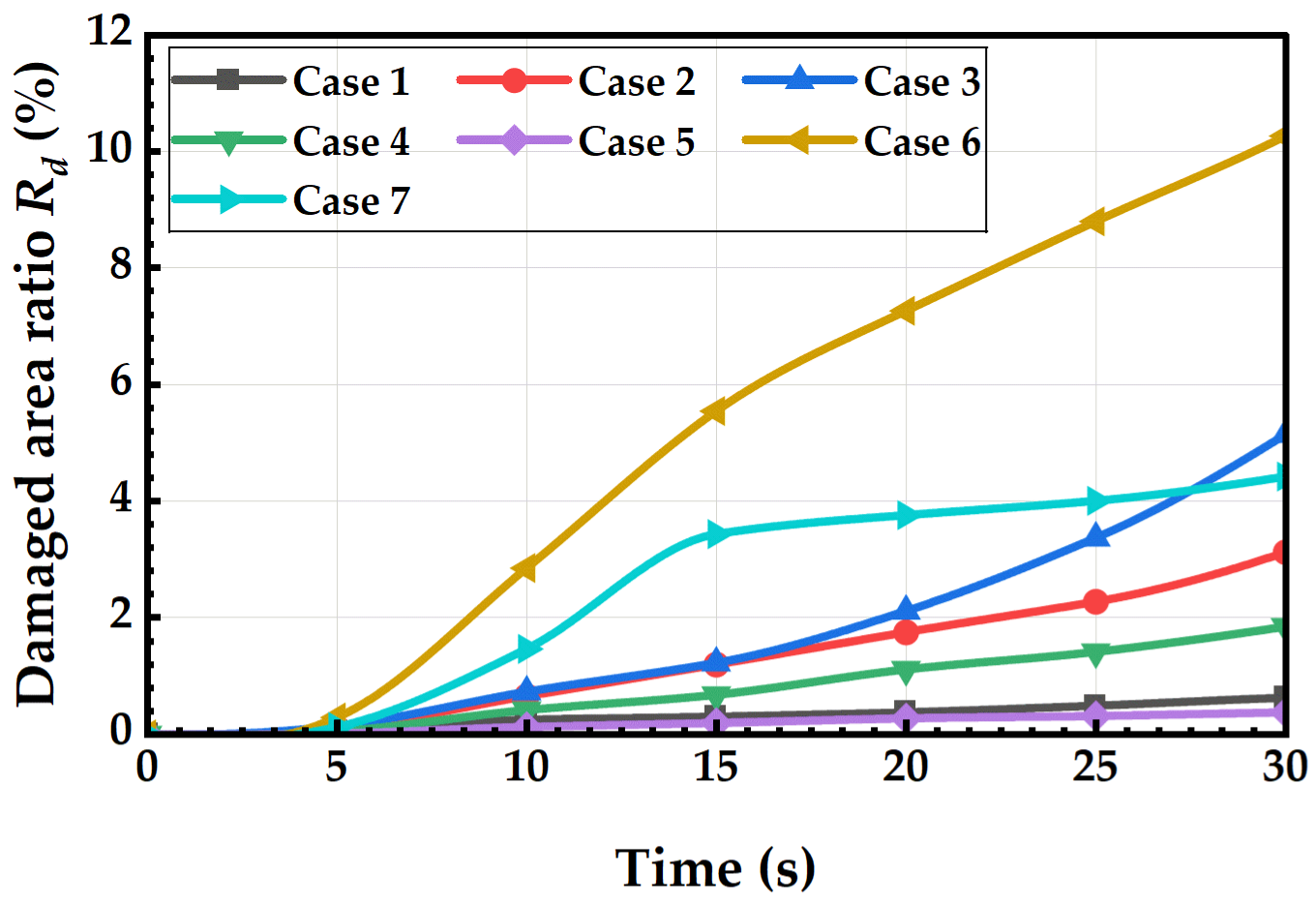
Figure 4 shows the spatiotemporal distribution of HDR damage variables for seven fracturing cases at injection times of 10 s, 20 s, and 30 s. In all cases, tensile damage cracks initiate from the central wellbore location, primarily due to continuous fluid pressurization causing significant tensile stress concentration in the surrounding HDR. Under different injection fluids, reservoir conditions, and injection parameters, distinct differences emerge in crack propagation range, main fracture length, branch development patterns, and overall damage extent. Case 1 uses water as the fracturing fluid under equal horizontal maximum and minimum principal stresses. During the full 30 s injection period, only a ring-shaped damaged zone forms around the wellbore, with a maximum radial width of just 0.027 m, and no radially penetrating macroscopic fractures develop. Figure 5 presents curves showing the damaged area ratio relative to the total model area across all cases over time. At 30 s, the HDR damaged area in Case 1 accounts for only 0.63% of the total HDR model area.
Figure 4.
Spatiotemporal distribution of HDR damage variable D at 10 s, 20 s, and 30 s for seven cases. Case 1: water; Case 2: baseline CO2; Case 3: higher reservoir temperature; Case 4: higher injection temperature; Case 5: lower injection pressure; Case 6: higher injection pressure; Case 7: anisotropic in situ stress.
Figure 5.
Temporal evolution of damaged area ratio Rd fraction over injection duration.
In contrast, Case 2—the baseline case—replaces water with CO2, generating three radial main fractures within 10 s of injection; by 30 s, the maximum extension length of a single main fracture reaches 0.088 m, increasing the damaged area ratio to 3.13%, five times higher than in water fracturing. It should be noted that the comparison between water fracturing (Case 1) and CO2 fracturing (Case 2) was conducted under identical injection pressure (30 MPa) rather than identical mass flow rate, because injection pressure is the primary controllable operational parameter in field fracturing. Under this condition, the difference in damaged area is mainly attributed to the combined effects of thermal shock and fluid properties. The low-temperature CO2 generates a large fluid–solid temperature difference, inducing additional thermal tensile stress that combines with fluid pressure and significantly lowers the HDR’s tensile failure threshold. Meanwhile, the lower viscosity and higher diffusivity of CO2 reduce seepage resistance and allow pressure and cold fluid to penetrate deeper along fractures, promoting multi-branch fracture propagation. Among these factors, thermal shock is the dominant mechanism controlling the reduction in the tensile failure threshold, while the lower viscosity of CO2 mainly governs the spatial extent of the pressure and temperature disturbance. Case 3 increases the initial reservoir temperature from 100 °C to 150 °C while maintaining other parameters identical to the baseline Case 2. The temperature difference between the reservoir and cold CO2 further widens, enhancing the thermal tensile stress effect and significantly promoting multi-branch crack development. At 30 s, the maximum fracture length in Case 3 increases to 0.119 m, with the damaged area ratio reaching 5.15%, a 64.5% increase compared to Case 2. Case 4 raises the CO2 injection temperature to 60 °C, substantially reducing the intensity of thermal shock; after injection, the maximum fracture length is only 0.069 m, and the damaged area ratio drops to 1.85%, a 42.5% decrease compared to Case 2, quantitatively confirming that the temperature gradient between the fluid and reservoir is the key factor controlling thermally induced HDR damage. The enhanced damage under CO2 fracturing cannot be attributed to a single factor. The temperature gradient is a key factor rather than a minor effect: increasing the reservoir temperature from 100 °C to 150 °C (Case 3) increases the damaged area ratio by 64.5%, while raising the CO2 injection temperature from 20 °C to 60 °C (Case 4) reduces it by 42.5%, both under otherwise identical conditions. Meanwhile, the low viscosity and high diffusivity of CO2 reduce seepage resistance and allow the cold fluid to penetrate deeper, which amplifies the thermal shock effect rather than replacing it. Therefore, thermal shock and fluid properties are strongly coupled, and a single-factor attribution—either to temperature alone or to viscosity alone—would be an over-generalization. Regarding sensitivity analysis on injection pressure, Case 5 applies a low-pressure injection of 25 MPa, 5 MPa lower than the baseline 30 MPa. Insufficient hydraulic seepage driving load fails to overcome the HDR’s tensile strength, resulting in only a narrow damaged ring of 0.025 m width around the wellbore at 30 s, with a damaged area ratio of merely 0.38%. Case 6 increases the injection pressure to 35 MPa, greatly enhancing fluid driving energy and inducing extensive multi-directional branching fractures; at 30 s, the maximum fracture extension length reaches 0.156 m, achieving the highest damaged area ratio among all cases at 10.27%, an increase of 228.12% compared to Case 2. Quantitative comparisons confirm that injection pressure is the primary controlling parameter governing the overall development scale of artificial fracture networks.
Cases 1~6 all assume uniform horizontal in situ stress conditions. Case 7 introduces an anisotropic stress field, where the stress differential strongly suppresses crack propagation in the direction of the minimum horizontal principal stress. All damage fractures extend exclusively along the direction of the maximum horizontal principal stress, forming a single straight main fracture without secondary branch cracks. At 30 s, the main fracture length is 0.071 m, with a damaged area ratio of 4.42%, exceeding that of Case 2. The results indicate that the horizontal stress anisotropy directly determines the propagation direction of fractures, while anisotropic stress inhibits the formation of complex, multi-branch fracture networks. From the temporal evolution characteristics, the damage development rate under all CO2 injection conditions exhibits a nonlinear acceleration trend between 10 and 30 s after injection. Taking baseline Case 2 as an example, the damaged area ratio was only 0.66% at 10 s, increased to 1.75% at 20 s, and further rose to 3.13% at 30 s. Under identical injection pressure, the damaged area ratio for CO2 fracturing (Case 2) reaches 3.13% at 30 s, approximately five times that of water fracturing (Case 1, 0.63%). Under continuous coupled fluid-thermal-mechanical loading, tensile damage in the surrounding HDR accumulates progressively, clearly demonstrating the typical progressive brittle failure behavior of tight reservoir HDRs during CO2 fracturing.
3.2. Temperature Field Distribution and Thermal Disturbance Characteristics
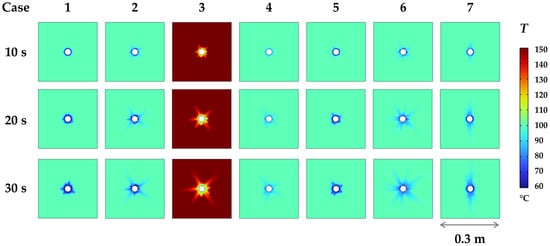
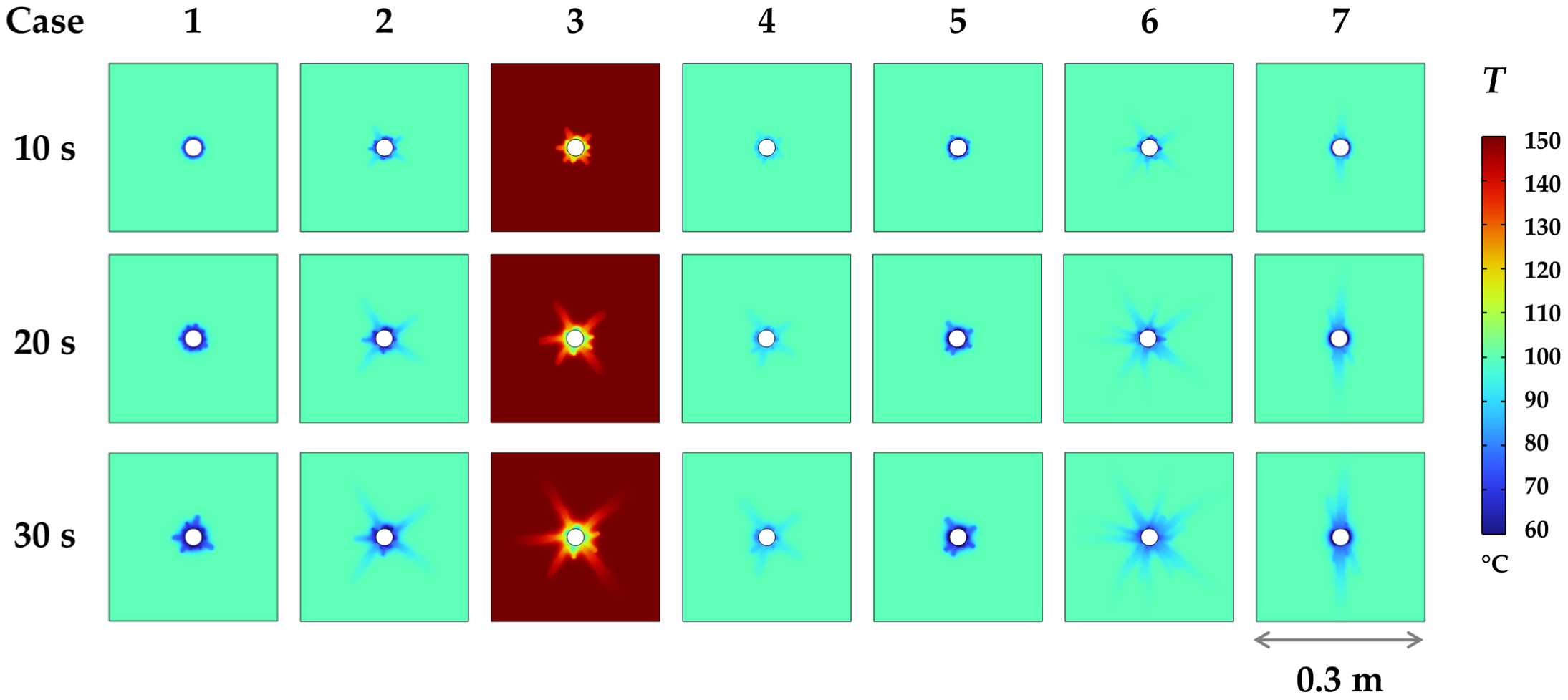
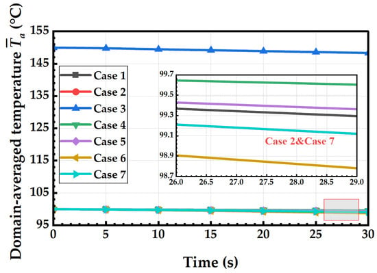
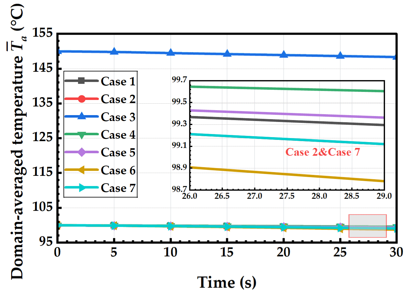
Figure 6 shows the temperature distribution contours of the reservoir at injection times of 10 s, 20 s, and 30 s for seven fracturing Cases. Cold working fluid is continuously injected from the central wellbore, forming distinct low-temperature cooling zones around the wellbore and along fracture propagation paths. Case 1 uses water fracturing; due to the small initial temperature difference between the water and the reservoir, heat exchange capacity is weak, resulting in only slight cooling within a narrow annular region near the wellbore, with no outward expansion of the cold zone observed by 30 s. Figure 7 presents the evolution of average temperature across the entire model domain over time. The overall model temperature remains stable near 99.3 °C throughout, decreasing by only 0.7 °C after 30 s, indicating minimal thermal disturbance in the formation. In baseline Case 2, CO2 is used as the fluid, creating radial low-temperature zones extending outward from the wellbore along three main fractures. The outline of these cold regions precisely matches the damaged fracture patterns. After 30 s, the average temperature drops to 99.1 °C~0.9 °C below the initial formation temperature. The infiltration of low-temperature along fractures enhances heat transfer pathways, while the thermal shock simultaneously induces additional tensile stress in the surrounding HDR. In Case 3, the original formation temperature is raised to 150 °C, resulting in a temperature difference of 130 °C between the formation and CO2—the largest among all Cases. Clearly, the entire computational domain maintains a high-temperature base, with only localized cold zones near the wellbore and along fracture paths. At 30 s, the average temperature decreases by 1.6 °C. This large temperature contrast amplifies the thermal stress gradient on fracture surfaces, which is the key thermal mechanism behind the significantly greater fracture length and damaged area compared to baseline Case 2. In Case 4, the injection temperature of CO2 is increased to 60 °C, reducing the fluid–formation temperature difference to 40 °C. The extent of cold temperature diffusion around the wellbore becomes noticeably narrower, with the width of the cold zone smaller than that in baseline Case 2. After 30 s, the average temperature is 99.6 °C, dropping only 0.4 °C, indicating greatly weakened heat exchange intensity and reduced thermal tensile stress levels, directly leading to diminished HDR damage development.
Figure 6.
Spatiotemporal temperature distribution of HDR at 10 s, 20 s, and 30 s for seven cases. Case 1: water; Case 2: baseline CO2; Case 3: higher reservoir temperature; Case 4: higher injection temperature; Case 5: lower injection pressure; Case 6: higher injection pressure; Case 7: anisotropic in situ stress.
Figure 7.
Temporal evolution of domain-averaged temperature under different injection conditions.
Injection pressure directly controls the flow rate of CO2 and the scale of fracture propagation, thereby altering the range of thermal disturbance in the reservoir. In Case 5, with an injection pressure of 25 MPa, the seepage driving load for fluid flow is insufficient, resulting in only minor cooling near the wellbore wall. The average temperature after 30 s remains at 99.3 °C, showing weaker overall thermal disturbance than Case 2. In Case 6, the injection pressure increases to 35 MPa, enabling extensive extension of multi-branch fractures. Cold CO2 spreads deeply into the HDR mass along multiple fissures, producing the largest radial cold zone coverage among all Cases. After 30 s, the average temperature drops by 1.3 °C from the initial value. A broader low-temperature flow region forms a continuous thermal tensile stress zone, ultimately causing the normalized damaged area ratio to reach its peak across all Cases. Case 7 employs an anisotropic in situ stress field, allowing fractures to extend unidirectionally along the maximum horizontal principal stress direction. The temperature field exhibits vertical stripe-like cold zones without multi-directional radial cooling. After 30 s, the average temperature is 99.1 °C, similar to that of baseline Case 2. However, the shape of the thermal disturbance zone is constrained by fracture orientation, with significant thermal gradients occurring only on both sides of a single dominant fracture. Due to the absence of multi-directional thermal stress superposition, complex branched fracture networks cannot form.
A preliminary longer-time run (60 s, Case 2) shows that the damaged area ratio increases from 3.13% at 30 s to about 9.67% at 60 s, indicating that the fracture network continues to develop beyond 30 s, but the dominant THMD coupling mechanisms remain unchanged. The 30 s window is therefore sufficient to capture the governing mechanism, while longer injection times mainly extend the existing fracture network.
3.3. Pressure Field Evolution and Seepage Driving Effect
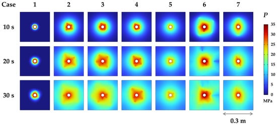
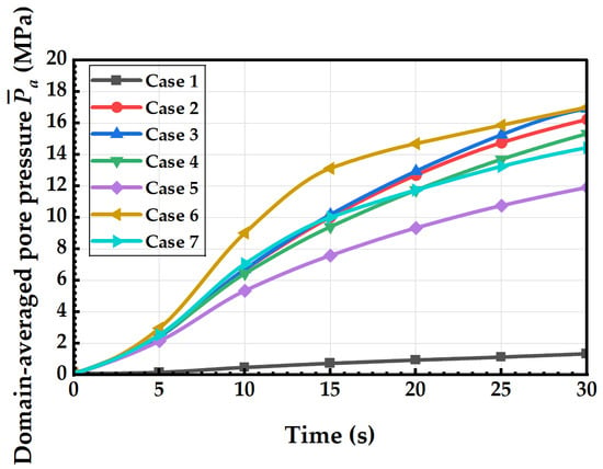
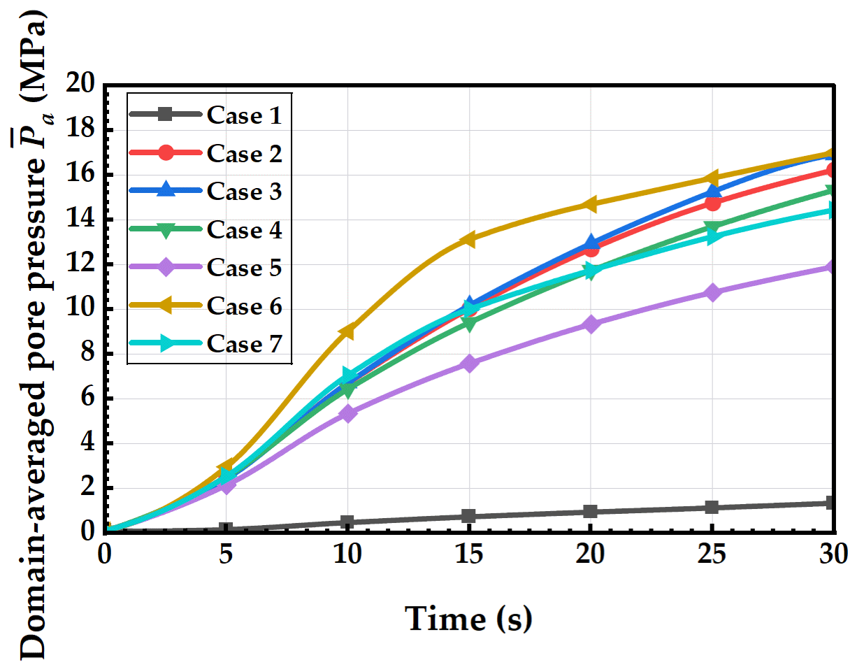
Figure 8 shows the spatiotemporal distribution of pore pressure fields in the HDR mass at injection times of 10 s, 20 s, and 30 s. In Case 1, the permeability is low, making it difficult for pressure energy to propagate into deeper HDR zones. Only a narrow annular high-pressure zone forms around the wellbore, with no significant radial expansion of the high-pressure disturbance by 30 s. Figure 9 presents the evolution curves of average pore pressure across the entire HDR mass under each condition over time. The average pore pressure increases very slowly in this case, reaching only 1.3 MPa at 30 s—the final state—significantly lower than in other CO2 fracturing Cases. The tensile seepage driving load provided by fluid loading is severely insufficient, preventing the formation of macroscopic propagating fractures throughout the process; only ring-shaped micro-damage develops near the wellbore wall. In the reference case (Case 2), pore pressure continuously spreads outward along three radial fractures, forming a cross-shaped high-pressure zone extending radially. As injection duration increases from 10 s to 30 s, the average pore pressure across the entire domain steadily rises, reaching 16.2 MPa at 30 s. High-pressure flow pathways expand simultaneously, and the tensile load induced by fluid pressure combines with thermal tensile stress caused by temperature differences to promote extensive tensile damage in the HDR.
Figure 8.
Spatiotemporal pore pressure distribution of HDR at 10 s, 20 s, and 30 s for seven cases. Case 1: water; Case 2: baseline CO2; Case 3: higher reservoir temperature; Case 4: higher injection temperature; Case 5: lower injection pressure; Case 6: higher injection pressure; Case 7: anisotropic in situ stress.
Figure 9.
Temporal evolution of domain-averaged pore pressure .
In Case 3, the high-temperature reservoir significantly reduces the viscosity of CO2 fluid, decreasing seepage resistance and enabling easier transmission of pore pressure along fractures into deeper HDR regions. The high-pressure disturbance coverage in the contour plot is substantially larger than in the reference case (Case 2). At 30 s, the average pore pressure reaches 16.9 MPa—an increase of 4.3% compared to Case 2. The broader high-pressure flow field combined with stronger thermal gradients is the hydro-mechanical driver behind the greater fracture development and larger damaged area observed in this case. In Case 4, the fluid temperature difference decreases, reducing the extent of thermally induced fracture development. Both the number and width of flow channels decrease, restricting the outward diffusion of pore pressure and resulting in a noticeably narrower radial dimension of the high-pressure zone. At 30 s, the average pore pressure across the entire domain is 15.3 MPa—a reduction of 5.6% compared to the reference case (Case 2). The weakened seepage pressure driving effect directly leads to reduced HDR damage.
Injection pressure is the key parameter controlling the rate of pore pressure accumulation and the extent of disturbance. In Case 5, the input fluid energy decreases, significantly slowing the rate of pore pressure buildup and confining the high-pressure zone to areas immediately adjacent to the wellbore. At 30 s, the average pore pressure is only 11.9 MPa—the lowest value among all CO2 cases. The tensile load exerted by the fluid is insufficient to overcome the HDR’s tensile strength, resulting in only a narrow damage ring around the wellbore. In Case 6, the fluid-driven energy is greatly enhanced, leading to fully developed multi-branch fracture networks. Pore pressure spreads outward along multiple fractures, creating a large-scale square-shaped high-pressure disturbance zone, with local maximum pore pressures approaching the upper limit of the color scale at 35 MPa. The final value at 30 s reaches 17 MPa, and sufficient seepage pressure continuously provides tensile seepage driving load for fracture propagation, ultimately forming the largest-scale damage fracture network among all cases.
In Case 7, fractures extend unidirectionally along the direction of maximum horizontal principal stress, and the high-pressure pore pressure zone appears as a vertical elliptical shape, without multi-directional radiating pressure disturbance bands. At 30 s, the average pore pressure across the entire domain is 14.4 MPa, lower than in the reference case (Case 2). The in situ horizontal stress anisotropy restricts the formation of multi-directional flow pathways, allowing pore pressure to transmit only along a single main fracture, lacking the effects of multi-directional pressure superposition. Furthermore, in all cases, the average pore pressure across the entire domain exhibits a nonlinear growth trend with injection time. During the initial phase (0~15 s), the slope of the curve is steeper, indicating rapid pore pressure accumulation. From 15 to 30 s, the growth rate slightly slows down, corresponding to the physical process of continuous fracture extension and dissipation of pressure energy into deeper HDR zones. Case 6 exhibits the optimal pressure accumulation rate throughout the entire process, while Case 5 and 1 show significantly weaker pressure increases.
3.4. Evolution Law of Weighted Average Temperature and Injection Mass Flow
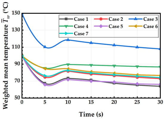
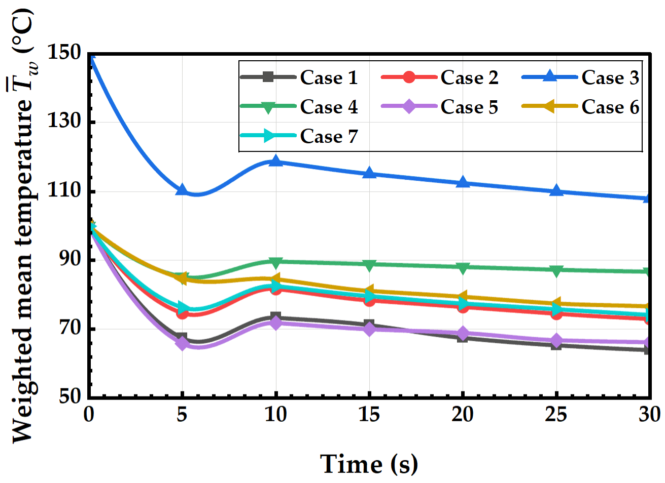
Figure 10 shows the evolution of weighted average HDR temperature under different conditions over injection time. is the arithmetic mean temperature over all elements in the computational domain, while is the weighted mean temperature weighted by element area. All cases exhibit a three-stage temperature behavior: an initial rapid drop, followed by a slight recovery, and then a slow, continuous cooling. From 0 to 5 s, low-temperature fluid is rapidly injected, causing intense heat exchange between the wellbore and surrounding HDR, resulting in a significant temperature decline across the entire domain at rates of 6.5 °C/s, 5 °C/s, 8 °C/s, 2.9 °C/s, 6.8 °C/s, 3 °C/s, and 4.7 °C/s, respectively. Between 5 and 10 s, crack propagation brings more high-temperature formation HDR into the heat exchange process, leading to a slight temperature rebound. From 10 to 30 s, the low-temperature fluid continues to seep through fractures, causing a gradual and steady decrease in reservoir average temperature. Case 3, with an initial formation temperature of 150 °C, shows significantly higher weighted average temperatures throughout compared to other cases with 100 °C formation temperatures. The minimum temperature reaches 110 °C at 5 s and stabilizes at 108 °C at 30 s, exhibiting the largest fluid–HDR temperature difference and strongest thermal seepage driving load for heat transfer. Case 4, with an injected fluid temperature of 60 °C, has the smallest temperature contrast, resulting in the weakest overall cooling effect, with the average temperature stabilizing at 87 °C after 30 s. In Cases 1 (clean water) and 5 (low pressure), insufficient development of flow pathways limits the extent of thermal disturbance, resulting in final average temperatures of 64 °C and 66 °C, respectively. Cases 6 (high pressure) and 7 (anisotropic in situ stress) show cooling magnitudes intermediate between the baseline Case 2, with average temperatures of 77 °C and 74 °C at 30 s, respectively. Multiple branch fractures enhance overall heat exchange, whereas single dominant fractures limit the effective heat transfer area.
Figure 10.
Temporal evolution of weighted mean temperature throughout injection.
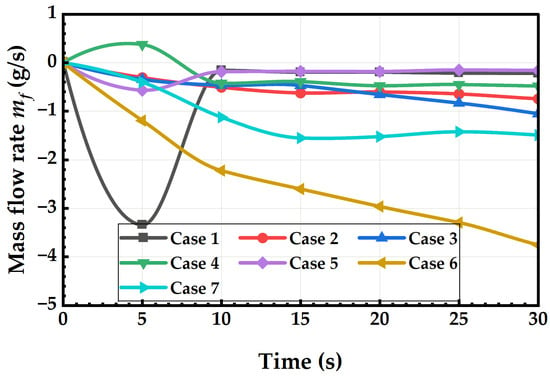
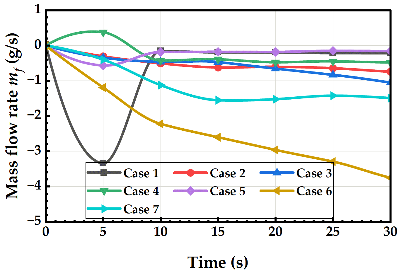
Figure 11 presents the mass flow rate variation along the wellbore cross-section. From 0 to 5 s, fluid rapidly enters the system, and flow rates quickly reach peak values. Case 6, with an injection pressure of 35 MPa, exhibits the strongest seepage driving load for fluid flow, showing a continuous negative increase in mass flow rate, reaching −3.8 g/s at 30 s, indicating substantial and sustained fluid infiltration into the formation. Case 1, involving clean water with high viscosity and strong permeability resistance, achieves a maximum flow rate of only −3.3 g/s at 5 s, and the flow rate rapidly approaches −0.15 g/s after 10 s, indicating almost no sustained deep penetration. Case 4, using high-temperature CO2 with lower viscosity, briefly experiences positive mass backflow initially, but overall seepage intensity remains weaker than the baseline Case 2. Case 5, under low-pressure conditions, lacks sufficient seepage driving load for fluid flow, resulting in the lowest absolute flow rate throughout, approaching 0.18 g/s after 10 s, meaning that fluid remains largely confined near the wellbore. Cases 2, 3, and 7 show similar flow evolution trends, with stable-phase flow rates maintained between −0.6 and −1.5 g/s, indicating moderate seepage velocities. Therefore, injection pressure directly controls the mass flow rate of fluid seepage, while the temperature difference between the formation and the injected fluid determines the overall cooling magnitude of the reservoir. Greater seepage flow leads to wider diffusion of low-temperature fluid and a more pronounced reduction in the reservoir’s weighted average temperature. The evolution of the temperature field and seepage field is highly coupled, jointly regulating HDR thermal stress and damage propagation behavior.
Figure 11.
Transient evolution of cross-sectional mass flow rate at the injection wellbore.
3.5. Energy Evolution Analysis of THMD Coupling Fracturing System
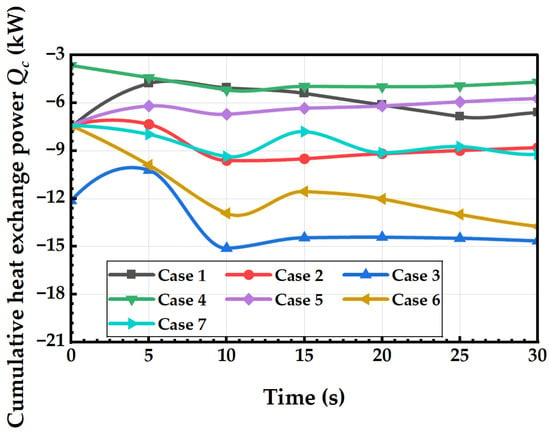
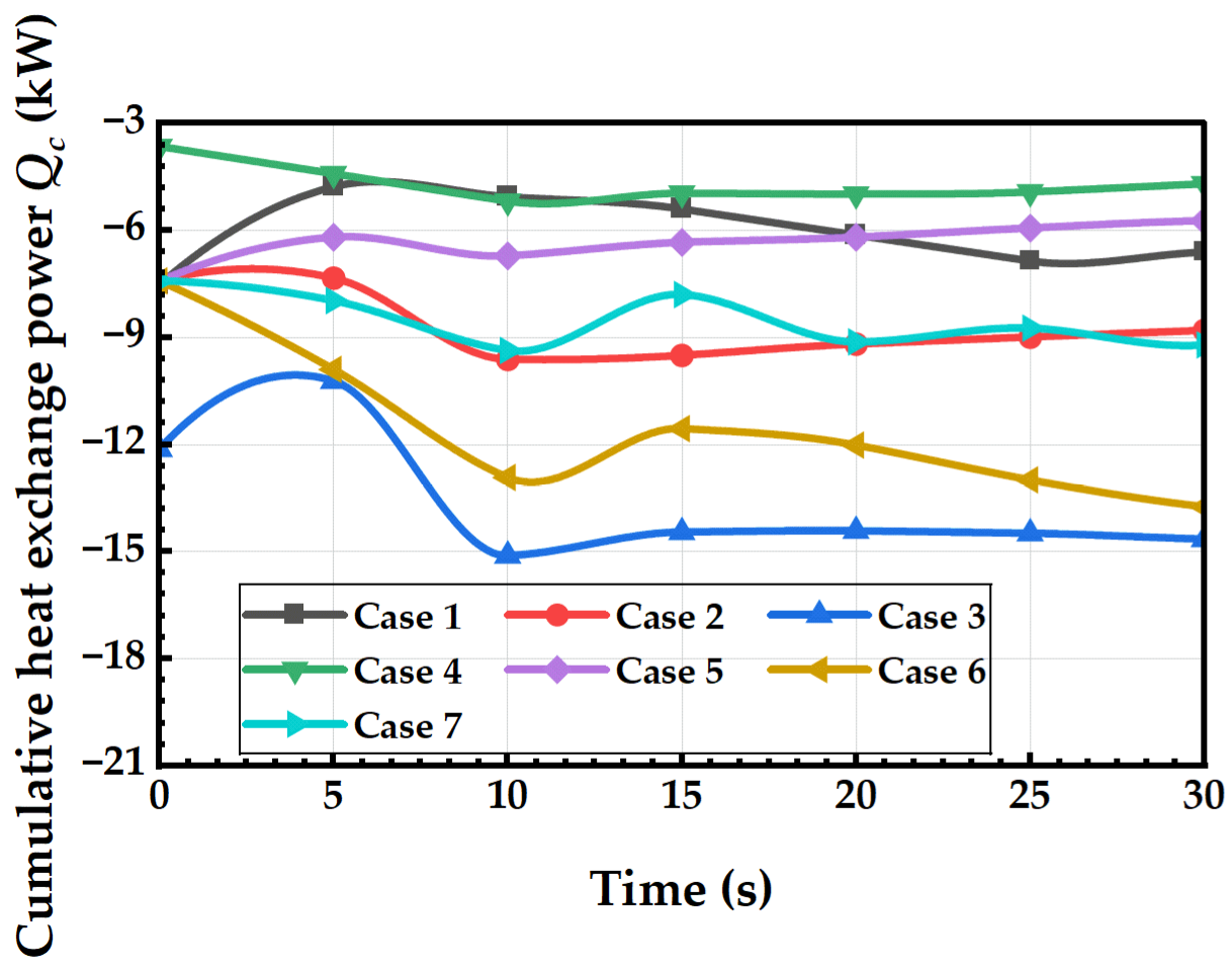
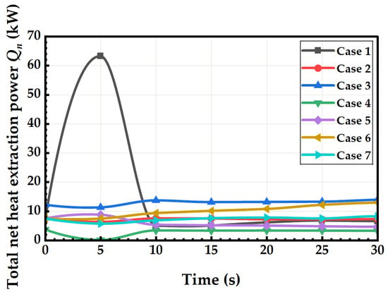
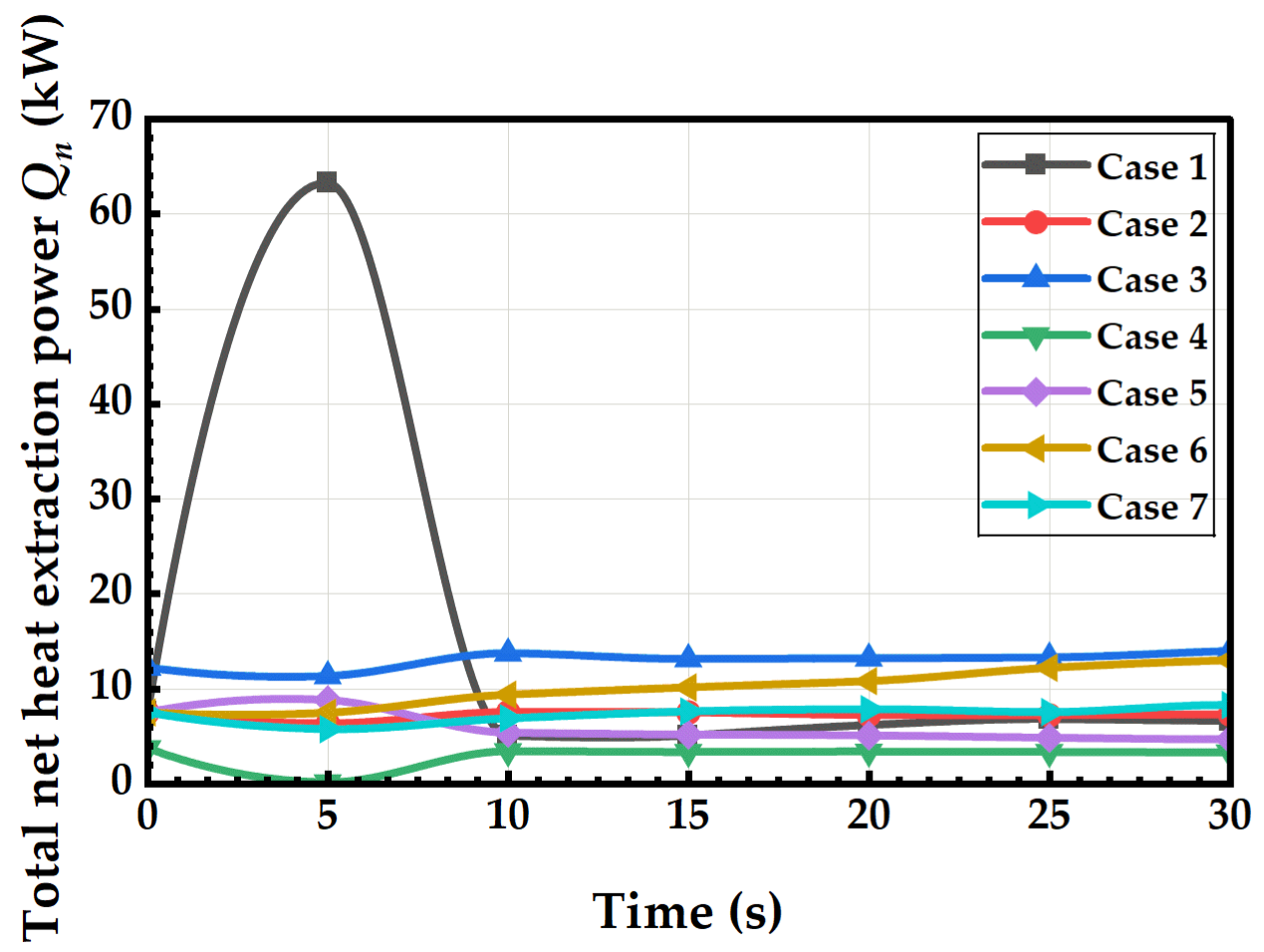
The energy analysis addresses a specific question: how the thermal, hydraulic, and mechanical driving forces jointly govern damage accumulation and fracture propagation. The cumulative heat exchange rate characterizes the overall thermal driving intensity, the instantaneous heat consumption rate characterizes the transient heat transfer power controlled by the fracture surface area, and the accumulated strain potential energy characterizes the mechanical energy stored in the HDR. Since crack initiation and propagation require continuous strain energy accumulation, the accumulated strain potential energy can serve as a direct energy measure of damage evolution. This is confirmed by the results: in Case 6, the sustained high injection pressure drives continuous strain energy accumulation, reaching 2 kJ at 30 s (11.1 times that of Case 2), corresponding to the highest damaged area ratio of 10.27%, whereas Cases 4, 1, and 5 show negligible strain energy and limited damage. These energy indicators are therefore not independent quantities, but different manifestations of the same coupled THMD fracturing process. Based on these indicators, Figure 12, Figure 13 and Figure 14 illustrate the evolution of total cumulative energy rate, instantaneous total net heat consumption rate, and total potential energy of the HDR mass over injection time under different conditions, quantitatively characterizing the heat transfer intensity and mechanical energy accumulation features of the fracturing system under various parameters from an energy balance perspective. Negative values in Figure 12 indicate continuous heat release from the system; the larger the absolute value of the curve, the stronger the overall heat exchange between the formation and low-temperature CO2. The total cumulative energy rate remains negative across all scenarios, showing a trend of rapid initial decline, slight fluctuations in the middle stage, and gradual stabilization in the later stage. During 0~10 s, the rapid injection of low-temperature fluid enhances the fluid–solid temperature difference, causing the cumulative heat release rate to quickly reach its minimum. From 10 to 30 s, the fracture network becomes largely established, leading to a stabilized heat exchange area and a slight recovery followed by slow convergence of the cumulative energy rate curve. Among them, Case 3, with an initial reservoir temperature of 150 °C, exhibits the largest fluid–solid temperature difference, achieving a total cumulative energy rate as low as −14.6 kW at 30 s—the highest overall heat exchange among all cases. Case 6, under high-pressure conditions (injection pressure of 35 MPa), has numerous flow pathways, resulting in a final cumulative energy rate of −13.7 kW, making its heat exchange scale second only to Case 3. Case 4, with an increased injection temperature of 60 °C, shows the weakest thermal contrast, maintaining a stable cumulative energy rate within the range of –4.4 to –5.2 kW throughout, indicating the lowest overall heat transfer intensity. Cases 1 (pure water) and 5 (low pressure) exhibit limited seepage development and insufficient heat exchange area, resulting in significantly lower cumulative heat release compared to the baseline CO2 case (Case 2). In Case 7, under anisotropic in situ stress conditions, only a single main fracture propagates, yielding a final cumulative energy rate of −9.2 kW, with a heat exchange scale slightly lower than that of Case 2. The early-stage thermal surge in Case 1 is attributed to the combined effect of high water viscosity and limited seepage pathways. Because water viscosity is much higher than that of CO2, the injected water cannot penetrate deeply into the HDR matrix and instead accumulates near the wellbore wall, forming a localized zone of steep temperature gradient and intense heat exchange. This produces a sharp peak in the instantaneous heat consumption rate (63 kW at 5 s). Once the near-wellbore region is cooled and no sustained flow pathway is established, the heat exchange area stops expanding, and the heat consumption rate rapidly drops back to about 5 kW. In contrast, CO2 has much lower viscosity and can spread along fractures, so the heat exchange area grows continuously, and no sharp peak appears. This transient response is qualitatively consistent with the near-wellbore rapid cooling and limited heat-exchange area observed in thermal shock experiments, but direct quantitative validation of the 63 kW peak has not been performed because dedicated near-wellbore transient heat-exchange experiments are not yet available.
Figure 12.
Transient evolution of cumulative heat exchange power of HDR.
Figure 13.
Temporal variation in net heat extraction power .
Figure 14.
Transient variation in accumulated strain potential energy .
Figure 13 shows the instantaneous total net heat consumption rate, reflecting the momentary power at which heat is transferred from the formation to the fluid at any given time. The evolution pattern of Case 1 (clean water) is unique: due to the significantly higher viscosity of clean water compared to CO2, during the initial injection stage, the fluid becomes trapped near the wellbore wall, forming localized concentrated heat transfer. As a result, the instantaneous heat consumption rate sharply rises to a peak of 63 kW at 5 s, after which seepage ceases, and the heat transfer power rapidly drops back to 5 kW. For all other CO2 cases, the instantaneous heat consumption rate remains relatively stable with minor fluctuations throughout. In Case 3, the high formation temperature provides continuous seepage driving load for heat transfer, maintaining a steady heat consumption rate between 13.3 and 14 kW—the highest among all CO2 cases. In Case 6, the high pressure results in greater seepage flow, stabilizing the instantaneous heat consumption rate at 12.2~13 kW. In Case 4, due to reduced fluid temperature difference, the instantaneous net heat consumption rate remains below 3.8 kW over an extended period, even briefly turning negative—indicating that the fluid transfers heat back into the surrounding HDR. For low-pressure Case 5 and the isotropic stress condition Case 7, the instantaneous heat consumption rates fall around the baseline Case 2, with overall heat transfer power maintained between 4.7 and 8.3 kW.
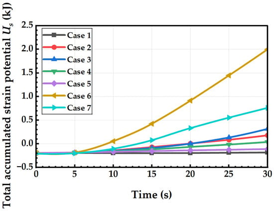
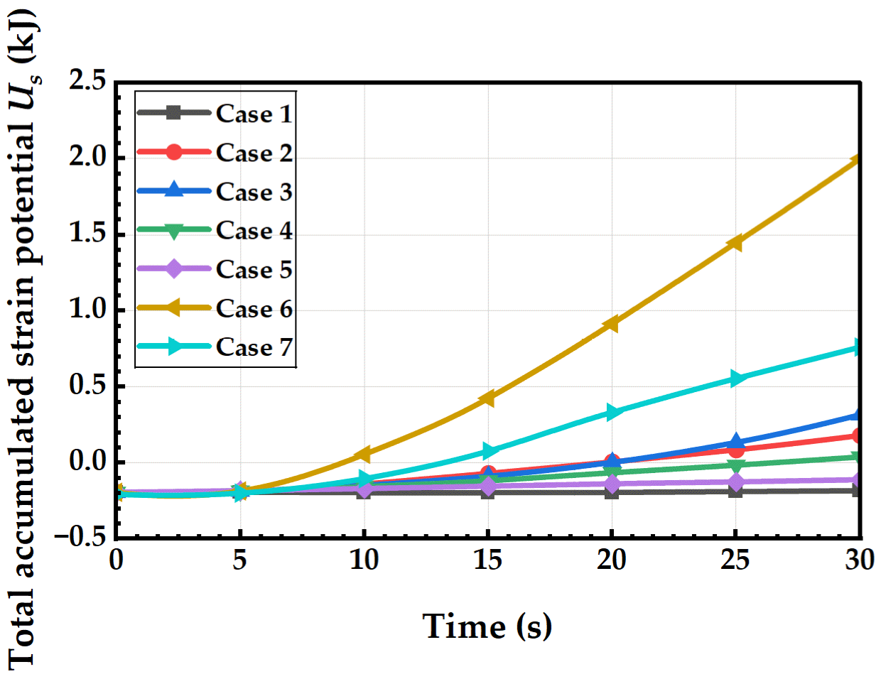
Figure 14 illustrates the total potential energy of the HDR mass, representing the strain energy stored in the HDR due to both fluid pressure and in situ stress. A continuous increase in potential energy indicates ongoing crack propagation and cumulative HDR damage. During the initial 0~5 s, fluid pressure has not yet fully diffused, resulting in slight decreases in potential energy across all cases, dominated by compressive energy storage in the surrounding HDR. After 5 s, seepage pathways gradually initiate and extend, leading to tensile damage development in the HDR mass. The total potential energy then shifts from negative to positive and increases linearly. Under high-pressure conditions (Case 6), the rate of potential energy growth is significantly higher than in other cases, reaching a total of 2 kJ at 30 s—11.1 times that of the baseline Case 2 (0.18 kJ). The sustained high injection pressure continuously applies tensile loading to the HDR, accumulating substantial strain energy.
In Case 3, the combined effect of elevated formation temperature and enhanced thermal tensile stress results in a total potential energy of 0.32 kJ at 30 s. For anisotropic stress conditions in Case 7, only unidirectional fractures develop, yielding a final potential energy of 0.76 kJ. Cases 4, 1, and 5 exhibit limited tensile damage due to insufficient temperature gradients, weak fluid permeability, or low injection pressures, resulting in total potential energy remaining near zero throughout, with almost no accumulated strain energy. Overall, the original formation temperature determines the upper limit of heat exchange, injection pressure controls the scale of fluid flow and the rate of potential energy accumulation, and the in situ stress state governs fracture propagation patterns. These three factors collectively regulate the total heat exchange capacity and the evolution of mechanical damage energy in the reservoir. There is a significant positive correlation between heat dissipation rate and total HDR potential energy: greater heat transfer intensity and higher seepage flow lead to increased accumulated strain potential energy, resulting in more pronounced macroscopic fracture and damage development. This confirms, from an energetic perspective, the coupled hydro-thermal-mechanical fracturing mechanism in CO2 stimulation.
4. Conclusions
This study develops a two-dimensional plane strain numerical model coupling fluid flow, heat transfer, stress, and damage to compare and analyze the evolution of reservoir damage, temperature, pore pressure, and energy under hydraulic fracturing and multi-parameter-controlled CO2 fracturing. It systematically reveals the coupled fracturing mechanisms in tight HDR formations during CO2 fracturing. The main conclusions are as follows:
- Compared with water fracturing, CO2, as a low-temperature fluid, can induce significant thermal tensile stresses around the wellbore. When coupled with fluid-induced pore pressure, it substantially reduces the HDR’s tensile failure threshold, facilitating the formation of complex, multi-branching radial fracture networks. Within a 30 s injection period, the damaged area ratio under CO2 conditions can reach up to 5 times that of water fracturing, indicating that under the baseline conditions considered in this study, the thermal shock effect is the core mechanism behind CO2’s high-efficiency fracturing.
- Formation initial temperature and CO2 injection temperature directly determined the magnitude of the fluid–solid temperature difference. A larger temperature difference results in stronger thermal tensile stresses, simultaneously increasing both total heat exchange in the reservoir and the extent of HDR damage. At a reservoir temperature of 150 °C, the damaged area ratio increases by 64.5% compared to the baseline condition at 100 °C; raising the injection fluid temperature to 60 °C weakens the thermal gradient, reducing the damaged area ratio by 42.5%. This demonstrates that the temperature gradient is a key thermal parameter controlling the development of thermal damage.
- Injection pressure is the primary controlling factor for fracture propagation. High injection pressure expands the fluid flow range, elevates overall pore pressure levels, and increases the strain potential energy of the HDR mass. Under a high-pressure condition of 35 MPa, the most complex fracture network forms across all scenarios, with the total potential energy of the HDR reaching 11.1 times that of the baseline case. In contrast, low-pressure injection provides insufficient seepage driving load for fluid flow, resulting only in minor damage rings near the wellbore and failing to generate extensive macroscopic fractures.
- In situ stress anisotropy significantly constrains fracture propagation patterns. Uniform horizontal in situ stress promotes the development of multi-directional branch fractures, whereas a difference in horizontal principal stresses causes fractures to propagate unidirectionally along the maximum horizontal principal stress, preventing the formation of complex fracture networks.
- Strong coupling exists among the multiple physical fields. Increasing injection pressure enhances fluid mass flow rate and expands the low-temperature flow and heat exchange zone, leading to simultaneous increases in cumulative heat exchange, instantaneous heat dissipation rate, and accumulated strain potential energy in the HDR mass, ultimately resulting in synchronized expansion of damage and fracture scale. This coupled evolution pattern of fluid-flow, heat-transfer, and mechanical behavior provides theoretical support for optimizing operational parameters in CO2 fracturing of tight reservoirs.
The proposed model is mainly valid within the tested ranges: reservoir temperature 100~150 °C, injection temperature 20~60 °C, injection pressure 25~35 MPa, and horizontal stress 10~12 MPa. Extrapolation beyond these ranges should be treated with caution, since the NIST REFPROP database only guarantees CO2 property accuracy within 17~227 °C and 0.1~40 MPa, while the coupled THMD response has been verified only under the conditions considered here.
The present 2D plane-strain results reveal the mesoscopic coupling mechanisms of CO2 fracturing in HDR but cannot be directly generalized to field-scale 3D EGS stimulation because the vertical stress component and out-of-plane fluid flow are neglected.
The CO2 properties are updated from NIST REFPROP based on local temperature and pressure; explicit phase-transition dynamics and local density fluctuations during rapid depressurization are not considered.
The baseline values of permeability, heat transfer coefficient, and Weibull homogeneity index were selected to represent typical granite properties. The qualitative conclusion that CO2 fracturing enhances damage compared with water fracturing is controlled by the reservoir–fluid temperature difference and is therefore expected to remain valid, although the absolute damaged area may vary with these parameters.
For field applications, the present results suggest a two-step operational strategy. First, the injection pressure should be kept above the fracture initiation threshold but below the fault reactivation threshold; in this study, the fracture network complexity increases significantly when the injection pressure rises from 25 MPa to 35 MPa, while a further increase may risk reactivating pre-existing faults. Second, the injection rate should be controlled so that the bottom-hole pressure remains below the minimum principal stress plus the tensile strength of the rock, which corresponds to the upper bound of the stable injection window. Within this window, a lower injection temperature is preferred because it enhances the thermal gradient and promotes multi-branch fracture propagation. Quantitative field criteria require calibration with site-specific stress, permeability, and fault distribution data.
Author Contributions
Conceptualization, X.S., P.L. and X.G.; methodology, X.S. and P.L.; software, X.S. and X.G.; validation, X.S., P.L. and X.G.; formal analysis, L.L. and Q.W.; investigation, X.S., P.L. and L.L.; resources, X.S. and X.Y.; data curation, X.S. and X.Y.; writing—original draft preparation, X.S. and L.L.; writing—review and editing, X.Y.; visualization, X.G. and Q.W.; supervision, X.Y.; project administration, X.S. and X.Y.; funding acquisition, X.S. All authors have read and agreed to the published version of the manuscript.
Funding
This research was funded by Deep Earth Probe and Mineral Resources Exploration—National Science and Technology Major Project, grant number 2024ZD1004106, and Synergistic Mechanisms of Locally Miscible CO2 Fracturing Coupling Geothermal Stimulation and Carbon Storage, grant number YCSY2025YYJC-B-01.
Data Availability Statement
The original contributions presented in this study are included in the article. Further inquiries can be directed to the corresponding author.
Conflicts of Interest
Authors Xiao Sun, Pan Luo, and Xing Guo are affiliated with Shaanxi Yanchang Petroleum (Group) Co., Ltd., Xi’an, China. The remaining authors declare that the research was conducted in the absence of any commercial or financial relationships that could be construed as a potential conflict of interest.
Abbreviations
The following abbreviations and nomenclature are used in this manuscript:
| EGS | Enhanced geothermal system |
| HDR | Hot dry rock |
| THMD | Thermo-hydro-mechanical-damage |
| D | Damage variable |
| E | Elastic modulus (Pa) |
| ft | Uniaxial tensile strength (Pa) |
| fc | Uniaxial compressive strength (Pa) |
| G | Shear modulus (Pa) |
| k | Permeability (m2) |
| K′ | Drained bulk modulus (Pa) |
| p | Pore pressure (Pa) |
| t | Time (s) |
| T | Temperature (°C) |
| ui | Displacement component (m) |
| α | Biot coefficient |
| αT | Thermal expansion coefficient (1/°C) |
| εV | Volumetric strain |
| λM | Thermal conductivity of porous medium (W/(m·K)) |
| μ | Fluid dynamic viscosity (Pa·s) |
| ν | Poisson’s ratio |
| ρl | Fluid density (kg/m3) |
| (ρC)M | Heat capacity of fluid-saturated porous medium (J/(m3·K)) |
| σ1, σ3 | Maximum/minimum principal stress (Pa) |
| φ | Internal friction angle (°) |
| ϕ | Porosity |
References
- Emmanuel, J.K.; Ngabala, F.J. Global energy demand and the role of technological innovation towards renewable energy generation for economic growth and a cleaner environment: A review. Sustain. Environ. 2026, 12, 2633481. [Google Scholar] [CrossRef] [Scilit]
- Saha, S.; Islam, M. Potential for nano-enhanced molten salts in solar energy storage. Renew. Sustain. Energy Rev. 2025, 210, 115217. [Google Scholar] [CrossRef] [Scilit]
- Yuan, Y.; Zhang, X.; Yu, H.; Zhong, C.; Wang, Y.; Wen, D.; Xu, T.; Gherardi, F. Research progress and technical challenges of geothermal energy development from hot dry rock: A review. Energies 2025, 18, 1742. [Google Scholar] [CrossRef] [Scilit]
- Lu, J.; Jiang, W.; Pan, J.; Huang, J.; Wu, J.; Shang, D.; Wu, M.; Huang, G. Triaxial permeability behaviors and structural damage evolution of deep hot dry rock under different cooling stimulation. Geoenergy Sci. Eng. 2025, 251, 213896. [Google Scholar] [CrossRef] [Scilit]
- Zhang, L.; Wang, B.; Hu, M.; Shi, X.; Yang, L.; Zhou, F. Research progress on optimization methods of platform well fracturing in unconventional reservoirs. Processes 2025, 13, 1887. [Google Scholar] [CrossRef] [Scilit]
- Asem, P.; Nguyen, A.T.; Zhao, Y.; Labuz, J.F.; Bažant, Z.P. A Rapid Permeability Test of Low-Porosity Rock Based on Analysis of Initial Pressure Pulse Decay: Experimental Validation. Rock Mech. Rock Eng. 2026, 1–16. [Google Scholar] [CrossRef] [Scilit]
- Han, J.; Meng, X.; Li, Y.; Zhang, L.; Chen, J.; Huang, X.; Zhao, Y. Prospects and Challenges of Waterless/Low-Water Fracturing Technologies in Hot Dry Rock Geothermal Development. Processes 2026, 14, 920. [Google Scholar] [CrossRef] [Scilit]
- Suo, Y.; Guan, W.; Dong, M.; Zhang, R.; He, W.; Fu, X.; Pan, Z.; Guo, B. Study on the heat extraction patterns of fractured hot dry rock reservoirs. Appl. Therm. Eng. 2025, 262, 125286. [Google Scholar] [CrossRef] [Scilit]
- Deusner, C.; Bigalke, N.; Kossel, E.; Haeckel, M. Methane production from gas hydrate deposits through injection of supercritical CO2. Energies 2012, 5, 2112–2140. [Google Scholar] [CrossRef] [Scilit]
- Yin, T.; Song, J.; Liu, F.; Zhao, Y.; Li, S.; Li, X. Study on the dynamic tensile properties and damage mechanisms of thermally treated granite under acid cooling. Sci. Rep. 2026, 16, 6112. [Google Scholar] [CrossRef] [Scilit] [PubMed]
- Li, K.; Zhu, L.; Xiong, F.; Liu, J.; Xue, Y.; Cao, Z.; Zhou, Y.; Liang, X.; Ji, M.; Liu, G. Review on Thermal stimulation in deep geothermal reservoirs: Thermo-mechanical mechanisms and fracture evolution. Processes 2026, 14, 1199. [Google Scholar] [CrossRef] [Scilit]
- Li, J.; Peng, J.; Ranjith, P.; Li, Y. Energy partitioning evolution and crack interaction in granite under sequential thermal and mechanical loading. Rock Mech. Rock Eng. 2026, 59, 3133–3152. [Google Scholar] [CrossRef] [Scilit]
- Xu, K.; Chen, Y.; Li, M.; Yin, Q.; Zhang, Y.; Zhu, F.; Deng, J. Tensile Mechanical Properties and Damage Evolution Fracture Mechanism of Overlying Strata in Goaf under Thermo-mechanical Dynamic Coupling Conditions. J. Mater. Eng. Perform. 2026, 1–24. [Google Scholar] [CrossRef] [Scilit]
- Hu, M.; Fu, T.; Yang, X.; Peng, L.; Wang, C. Analysis of thermal shock-induced progressive damage and fracture criterion in granite. Eng. Fract. Mech. 2025, 329, 111593. [Google Scholar] [CrossRef] [Scilit]
- Xiong, W.; Jiangbo, X.; Xinyu, C.; Zixuan, Z.; Xia, Z.; Shaowei, W.; Peng, S.; Kun, L.; Qiang, S.; Fanghui, C. Effect of cooling methods on the mechanical properties and microstructural damage of high-temperature granite. Theor. Appl. Fract. Mech. 2025, 141, 105328. [Google Scholar] [CrossRef] [Scilit]
- Jiang, C.; Xu, L.; Chen, Y.; Liu, W.; Wang, B.; Liu, P.; Deng, B. Thermal behavior of minerals in shale and its influence on evolution of gas-flow channels under thermal shock. Gas Sci. Eng. 2024, 121, 205183. [Google Scholar] [CrossRef] [Scilit]
- Zhang, S.; Song, S.; Zhang, B.; Shen, B. Investigation of fracture propagation dynamics during multi-stage water injection shearing in fault-fracture reservoirs. Geomech. Energy Environ. 2025, 43, 100700. [Google Scholar] [CrossRef] [Scilit]
- Guo, G.; Zhang, Z.; Ye, Y.; Liu, Y.; Wang, J.; Wang, Q. A review of Wellhead pressure reduction methods in hydraulic fracturing. J. Pet. Explor. Prod. Technol. 2025, 15, 106. [Google Scholar] [CrossRef] [Scilit]
- Dai, H.; Yin, T.; Wu, Y.; Ma, J.; Guo, W.; Li, X. Characterization of fracture extension and damage evolution in hot dry rock by cycle hydraulic fracturing (CHF): Application of CHF in enhanced geothermal systems. Energy 2025, 330, 137007. [Google Scholar] [CrossRef] [Scilit]
- Liu, H.; Zhang, K.; Gu, Q.; Huang, B.; Du, Y.; Han, W. Experimental and theoretical investigations on the mechanical behaviors and fracture mechanism of hollow cylindrical granite under cyclic thermal shock. Eng. Fract. Mech. 2025, 331, 111712. [Google Scholar] [CrossRef] [Scilit]
- Li, Q.; Li, Y.; Song, D.; Guo, X.; Wang, R.; Wang, C.; Pan, J.; Wang, Z. Mechanism of Thermal Stress-Induced Fracture in Rock Masses under Liquid Nitrogen Fracturing Conditions. Energy Fuels 2025, 39, 21295–21309. [Google Scholar] [CrossRef] [Scilit]
- Lei, H.; Feng, B.; He, S.; Hu, B.; Chen, H.; Cheng, Y. Mineral Reactions and Reservoir Dynamic Response for Geothermal Energy Development Reservoir Reinjection from a Geochemical Perspective. Energies 2026, 19, 2395. [Google Scholar] [CrossRef] [Scilit]
- Li, C.; Duan, L.; Tan, S.; Chikhotkin, V.; Fu, W. Damage model and numerical experiment of high-voltage electro pulse boring in granite. Energies 2019, 12, 727, Erratum in Energies 2019, 12, 1875. [Google Scholar] [CrossRef] [Scilit]
- Liang, X.; Zhang, X.; Wang, W.; Liang, J.; Zhao, X.; Wu, K.; Zhang, Z. Revealing the crack formation mechanism of SS/NiTi heterogeneous materials fabricated by wire arc additive manufacturing. Mater. Charact. 2025, 223, 114879. [Google Scholar] [CrossRef] [Scilit]
- Zhang, J.; Lv, D.; Yin, D.; Zhang, X.; Li, X.; Fan, K. Gas recovery and flowback in trans-coal-limestone fracture: An in-situ wettability microscale visualization insight. Gas Sci. Eng. 2025, 142, 205707. [Google Scholar] [CrossRef] [Scilit]
- Yin, Z.; Zhang, F.; Wang, X.; Zhang, L.; Zhu, H. Four-dimensional stress induced by hydraulic fracturing and long-term extraction for shale gas well platforms: Implications for refracturing design. J. Rock Mech. Geotech. Eng. 2025, 18, 4349–4366. [Google Scholar] [CrossRef] [Scilit]
- Kong, C.; Sun, Y.; Zheng, D.; Li, Q.; Su, X.; Jia, Q.; Zhang, T.; Hou, J.; Dong, L.; Zhang, X. Analysis of the impact of CO2 injection on fracturing fluid flowback in shale gas wells. Sci. Rep. 2025, 15, 34223. [Google Scholar] [CrossRef] [Scilit] [PubMed]
- Li, Q.; Li, Q.; Cao, H.; Wu, J.; Wang, F.; Wang, Y. The crack propagation behaviour of CO2 fracturing fluid in unconventional low permeability reservoirs: Factor analysis and mechanism revelation. Processes 2025, 13, 159. [Google Scholar] [CrossRef] [Scilit]
- Lu, L.; Liu, G.; Li, Y.; Yang, X.; He, Y.-L. Experimental modifications for optimizing supercooling and phase separation in phase change materials: Calcium chloride hexahydrate and barium hydroxide octahydrate eutectic hydrate salts. Sol. Energy Mater. Sol. Cells 2025, 293, 113862. [Google Scholar] [CrossRef] [Scilit]
- Zhang, W.; Wang, C.; Guo, T.; He, J.; Zhang, L.; Chen, S.; Qu, Z. Study on the cracking mechanism of hydraulic and supercritical CO2 fracturing in hot dry rock under thermal stress. Energy 2021, 221, 119886. [Google Scholar] [CrossRef] [Scilit]
- Aliabadian, Z.; Sharafisafa, M.; Bahaaddini, M. A study on the efficiency of supercritical CO2 fracturing in hot dry rocks using coupled finite-discrete element method. Sci. Rep. 2026, 16, 23883. [Google Scholar] [CrossRef] [Scilit] [PubMed]
- Li, H.; Zhou, L.; Lu, Y.; Yan, F.; Zhou, J.; Tang, J. Changes in pore structure of dry-hot rock with supercritical CO2 treatment. Energy Fuels 2020, 34, 6059–6068. [Google Scholar] [CrossRef] [Scilit]
- Zhang, J.; Liu, Y.; Xia, J.; Lv, J. Heat extraction mechanisms of CO2-water mixed-phase flow in a single fracture of hot dry rock. Appl. Therm. Eng. 2025, 260, 125074. [Google Scholar] [CrossRef] [Scilit]
- Feng, C.; Wang, H.; Jing, Z. Investigation of heat extraction with flowing CO2 from hot dry rock by numerical study. Renew. Energy 2021, 169, 242–253. [Google Scholar] [CrossRef] [Scilit]
- Li, M.; Chen, Z.; Shu, B.; Moore, J.; McLennan, J. Analytical model for heat transfer of supercritical CO2 in a vertical hot dry rock fracture. Appl. Therm. Eng. 2025, 279, 127642. [Google Scholar] [CrossRef] [Scilit]
- Zhang, W.; Guo, T.-K.; Qu, Z.-Q.; Wang, Z. Research of fracture initiation and propagation in HDR fracturing under thermal stress from meso-damage perspective. Energy 2019, 178, 508–521. [Google Scholar] [CrossRef] [Scilit]
- Li, Z.; Li, L.; Huang, B.; Zhang, L.; Li, M.; Zuo, J.; Li, A.; Yu, Q. Numerical investigation on the propagation behavior of hydraulic fractures in shale reservoir based on the DIP technique. J. Pet. Sci. Eng. 2017, 154, 302–314. [Google Scholar] [CrossRef] [Scilit]
- Wei, C.; Zhu, W.; Yu, Q.; Xu, T.; Jeon, S. Numerical simulation of excavation damaged zone under coupled thermal–mechanical conditions with varying mechanical parameters. Int. J. Rock Mech. Min. Sci. 2015, 75, 169–181. [Google Scholar] [CrossRef] [Scilit]
- Cheng, L.; Luo, Z.; Xie, Y.; Zhao, L.; Wu, L. Numerical simulation and analysis of damage evolution and fracture activation in enhanced tight oil recovery using a THMD coupled model. Comput. Geotech. 2023, 155, 105244. [Google Scholar] [CrossRef] [Scilit]
- Wu, L.; Hou, Z.; Xie, Y.; Luo, Z.; Xiong, Y.; Cheng, L.; Wu, X.; Chen, Q.; Huang, L. Fracture initiation and propagation of supercritical carbon dioxide fracturing in calcite-rich shale: A coupled thermal-hydraulic-mechanical-chemical simulation. Int. J. Rock Mech. Min. Sci. 2023, 167, 105389. [Google Scholar] [CrossRef] [Scilit]
- Zhu, W.C.; Tang, C. Numerical simulation on shear fracture process of concrete using mesoscopic mechanical model. Constr. Build. Mater. 2002, 16, 453–463. [Google Scholar] [CrossRef] [Scilit]


Disclaimer/Publisher’s Note: The statements, opinions and data contained in all publications are solely those of the individual author(s) and contributor(s) and not of MDPI and/or the editor(s). MDPI and/or the editor(s) disclaim responsibility for any injury to people or property resulting from any ideas, methods, instructions or products referred to in the content. |
© 2026 by the authors. Licensee MDPI, Basel, Switzerland. This article is an open access article distributed under the terms and conditions of the Creative Commons Attribution (CC BY) license.