


Abstract
The LC-filtered permanent magnet synchronous motor (PMSM) drive system presents challenges due to its high-order characteristics, as well as the phase delay and voltage drop introduced between the inverter side and the motor side. These issues make traditional sensorless control methods difficult to apply directly. To address this, this paper proposes a sensorless control strategy based on a second-order generalized integrator (SOGI)-assisted high-order extended state observer (HOESO). This strategy relies solely on DC bus voltage and inverter-side currents to realize precise observation of the motor-side current and back electromotive force (BEMF), thereby significantly reducing system cost. Furthermore, the method enables gain parameter tuning merely by adjusting the observer bandwidth, and it also demonstrates that the system is stable when the estimated current is used to drive the capacitor current feedback active damping (CCFAD). In addition, the voltage differential components are extracted using the SOGI, effectively suppressing high-frequency noise interference. Experimental results obtained on an LC-filtered PMSM platform show that, under a 0.8 N·m step load at 600 rpm and 1200 rpm, the maximum motor-side current estimation errors are 0.66 A and 1.24 A, respectively, and the steady-state rotor position estimation errors are kept within 10°. Compared with direct differentiation, the SOGI-based differential extraction reduces the maximum BEMF estimation errors from 20.16 V and 47.54 V to 10.08 V and 12.96 V, respectively.
1. Introduction
The PMSM is widely used in various fields due to its advantages [1,2,3,4,5]. However, the use of the voltage source inverter (VSI) to drive a PMSM introduces output voltages with extremely high voltage change rates (du/dt) and abundant high-order harmonics due to the fast response of semiconductor devices [6]. This issue becomes particularly pronounced under specific operating conditions: for instance, in mining and deep-sea applications where long cables are required for power transmission, the combination of line impedance and pulsed voltages can easily induce overvoltages. This not only accelerates insulation aging in the motor but also gives rise to electromagnetic compatibility (EMC) issues, thus shortening the service life of the equipment [7].
To address the aforementioned challenges, inserting an LC filter is considered an effective solution. By means of this filter, the inverter output voltage is transformed into a sinusoidal waveform, thereby significantly suppressing du/dt and high-frequency harmonic voltages, protecting motor insulation, reducing bearing currents, and effectively mitigating motor vibration and noise. With the increasing application of wide-bandgap semiconductor devices (such as SiC and GaN) enabling higher switching frequencies, along with the growing number of long-cable transmission scenarios, the necessity of LC sine-wave filters has become increasingly prominent [8].
Nevertheless, adding an LC filter introduces new control challenges. The filter, together with the motor stator inductance, forms a high-order LCL network, which introduces an inherent resonant peak into the system. Without proper suppression, this can lead to system instability. Currently, the main methods for suppressing resonance include active damping (AD) and passive damping (PD) [9,10]. Since PD incurs additional power losses, research into AD has become particularly necessary. Among the proposed AD techniques, those employing feedback of a filter-state have proven to be more economical. In particular, CCFAD is widely adopted because it is easy to implement and effective resonance suppression [11]. However, in some special industrial applications where the inverter is located far from the motor, it is difficult to install additional current and position sensors to measure system state variables and position information. Therefore, achieving high-performance sensorless operation while ensuring system stability and effectively suppressing resonance has become a key technical issue that urgently needs to be resolved for the LC-filtered PMSM drive system.
By adding an LC filter, the overall order of the system is significantly increased, and noticeable phase delay and voltage drop are introduced between the inverter side and the motor side. Although various observer-based methods, such as sliding-mode observers [12], extended state observers [13], and finite-time or fixed-time disturbance observers [14], have been widely used for state estimation and disturbance reconstruction in motor drives and other nonlinear systems [15], traditional sensorless control methods designed for filterless PMSM drives are still difficult to apply directly to LC-filtered PMSM drives [16,17]. For example, in [18], a conventional algorithm based on a voltage-model rotor flux estimator was applied to a system equipped with an LC sine-wave filter. However, this approach requires the measurement of motor-side voltage and current, which not only increases hardware cost but also adversely affects system stability. Consequently, a method for reconstructing the rotor flux model based on LC filter parameters was proposed in [19], eliminating the need for additional voltage sensors and thereby reducing cost. Nevertheless, this approach, which relies on pure integration, introduces issues such as integrator drift. Similarly, in [20], the authors implemented a sensorless control system for an LC-filtered Interior PMSM (IPMSM) using an active flux observer. However, because the inverter-side voltage and current were directly used as substitutes for the motor terminal voltage and stator current, respectively, high-performance motor drive could not be achieved. Furthermore, in [21], the authors estimated the motor stator voltage and current using the filter output voltage and current. In [22], a virtual order reduction method was proposed to estimate the BEMF. By defining a weighted current from the inverter-side current and the motor-side current, the original third-order LCL model is reduced to a first-order virtual model, thereby simplifying the system. However, both [21] and [22] also require additional voltage or current sensors.
To reduce reliance on sensors, designing full-order observers is an effective approach. As proposed in [23], the adaptive full-order observer unifies the modeling of the LC filter and motor as a complete order-increasing system. By measuring only the inverter-side current, it achieves full-state estimation. What is more, at low speeds, the rotor position error is extracted through high-frequency signal injection to correct the adaptive full-order observer. Meanwhile, to simplify pole placement and observer structure in full-order state observers, a proportional-integral (PI) observer for surface-mounted permanent magnet synchronous motors (SPMSMs) is proposed in [24]. Furthermore, to enhance system robustness, full-order sliding-mode observers are designed to estimate system states in [25,26], with adaptive gain matrices improving estimation accuracy and dynamic performance. However, the full-order sliding-mode observer exhibits high dimensionality and requires the design of numerous sliding-mode gain parameters, leading to a complex tuning procedure.
In response to the above-mentioned problems, this paper proposes a sensorless control strategy based on a HOESO assisted by a SOGI for LC-filtered PMSMs. The main contributions of this paper are as follows:
(1) Compared with existing methods that require motor-side voltage or current sensors or directly substitute inverter-side variables for motor-side variables, a HOESO-based estimation method is proposed by uniformly modeling the LC filter and PMSM. The proposed method only requires the DC bus voltage and inverter-side currents to estimate both the motor-side current and BEMF, thereby avoiding additional motor-side voltage, current, and position sensors.
(2) Compared with other full-order observers that usually involve multiple gain matrices or several tuning parameters, the proposed HOESO adopts a bandwidth-based pole placement method. As a result, the observer gains can be determined by tuning only one bandwidth parameter, which greatly simplifies the parameter design procedure.
(3) The estimated motor-side current is further used for both current-loop feedback and CCFAD. Therefore, stable sensorless operation of the LC-filtered PMSM drive can be achieved without motor-side current sensors. In addition, the SOGI is introduced to extract the required differential components, which suppresses high-frequency noise amplification and improves the estimation accuracy of the motor current and BEMF.
The remainder of this paper is organized as follows. Section 2 establishes the equivalent model of the LC-filtered PMSM drive system. Section 3 presents the proposed SOGI-assisted HOESO-based sensorless control strategy, including the construction of the HOESO, stability analysis, CCFAD implementation using the estimated motor current, SOGI-based differential extraction, and comparison with existing sensorless methods. Section 4 provides the experimental validation and performance analysis of the proposed method. Finally, Section 5 concludes this paper.
2. Equivalent Model of the LC-Filtered PMSM
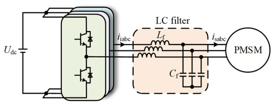
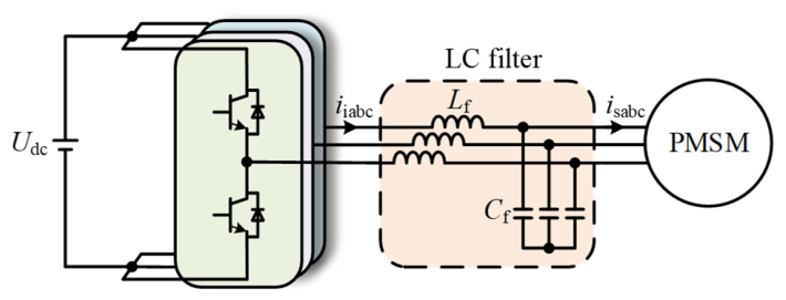
Figure 1 shows the configuration of the LC-filtered PMSM system. The LC filter is inserted between the inverter and the motor to improve the output voltage waveform, while the overall structure serves as the basis for the proposed control strategy and subsequent system analysis.
Figure 1.
Drive system of LC-filtered PMSM.
Where Udc is the DC bus voltage of the inverter, Lf and Cf are the inductor and capacitor of the LC filter, respectively, and iiabc and isabc are the inverter-side and motor-side three-phase currents, respectively.
The parameters of an LC filter should be selected based on the following principles. Lf is first selected according to the allowable voltage drop across the filter inductor. At the rated current and rated fundamental frequency, the voltage drop across Lf should generally be limited to 3–10% of the rated motor phase voltage [27]. This constraint ensures that the filter inductor can suppress high-frequency switching harmonics without introducing excessive fundamental voltage drop and phase delay. After Lf is determined, the resonant frequency(fres) of the LC sine-wave filter is selected. The resonant frequency should be higher than ten times the fundamental frequency(fb) and lower than one tenth of the sampling frequency(fsw), so that the filter has little influence on the fundamental component while effectively attenuating switching harmonics [28]. Finally, Cf is calculated based on the selected Lf and fres.
To reduce the model complexity of Interior Permanent Magnet Synchronous Motors (IPMSMs) in the two-phase stationary reference frame (αβ) caused by the salient-pole characteristic, the stator voltage equation based on active flux is expressed as [29]
where [usα, usβ]T, [isα, isβ]T, and [esα, esβ]T are the stator voltages, stator currents, and the motor BEMF in the αβ-axes, and isd is the current in the d-axis. Rs is the stator resistance; [Ld, Lq]T are the inductances in the dq axes; p is the differential operator; ψaf is the active flux oriented along the d-axis; and ψf, θe, and ωe are flux linkage, rotor angle, and synchronous angular velocity, respectively.
In the αβ axes, the equation of the LC filter can be expressed as
where [uiα, uiβ]T and [iiα, iiβ]T are the inverter-side voltages and currents in the αβ axes.
3. Proposed SOGI-Assisted HOESO Based CCFAD
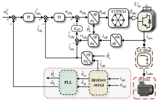
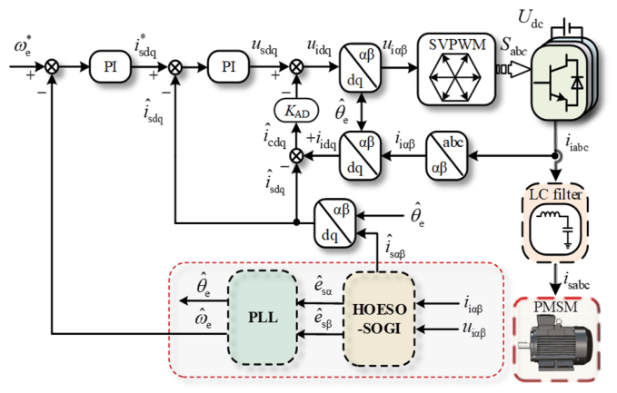
This section proposes an estimation method based on a HOESO assisted by a SOGI. Figure 2 illustrates its structure within a sensorless control system for an LC-filtered PMSM. And “*” represents the reference value. According to the structure, motor currents and BEMF can be estimated solely from inverter-side current measurements, thereby reducing the number of sensors used and controlling the system cost.
Figure 2.
Structure of LC-filtered PMSM drives using a SOGI-assisted HOESO.
3.1. The Construction of HOESO
According to (1) and (3), in the two-phase stationary reference frame, the mathematical model of the LC-filtered PMSM drive system can be derived as
Based on (4) and [30], the state variables x1-x3 can be defined as
Since the BEMF of the motor is not included in the above state variables, making it impossible to observe, the state variable x4 is further extended as
According to (4)–(6), a third-order integral series is established as
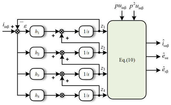
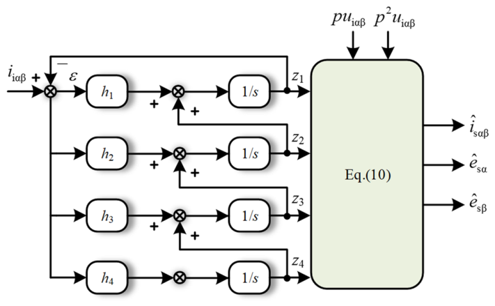
Subsequently, to estimate the states of the LC-filtered PMSM drive system, a HOESO is designed, whose expression is given as
where ε denotes the current estimation error, z1-z4 represent the estimates of the x1-x4, and h1-h4 are the respective adjustable gains.
For the sake of convenience in analysis, the HOESO parameters are set according to the pole configuration method described in [31], the adjustable gains h1-h4 can be selected as
where ω0 is the bandwidth of the ESO.
According to (5), (6) and (8), the estimated motor state variables can be expressed as
where “ˆ” represents the estimate variables.
Figure 3 shows a structure diagram of the HOESO. Based on Figure 3 and (8), Gz1-Gz4 represent the relationships between state variables.
Figure 3.
Structure diagram of the proposed HOESO.
According to (2) and (10), the estimated BEMF can be expressed as.
HOESO estimates that the BEMF contains a wealth of information regarding the rotor position. According to [32], this BEMF signal can be fed into a phase-locked loop (PLL) for phase locking and angle tracking, thereby enabling accurate estimation of the rotor electrical angle and providing a basis for sensorless estimation of the rotor position and speed.
After normalizing the BEMF, the error is output via the phase detector phase detector (PD)
Let denote the rotor position estimation error. When the PLL is close to the locked state, is sufficiently small. Therefore, based on the small-angle approximation, . Under this condition, the PD output can be regarded as an equivalent rotor position error. A PI is adopted in the loop filter (LF) to generate the motor electrical angular velocity from the obtained equivalent position error. In this process, the proportional component improves the dynamic response of the system, whereas the integral component eliminates the steady-state error, thereby enhancing the accuracy of rotor position estimation. Subsequently, by integrating the estimated angular velocity, we can obtain the estimated position of the rotor [33].
3.2. Stability Analysis
According to (5) and (6), the linear combination relationship between the true BEMF and state variables can be expressed as
It can be seen that both the actual BEMF and the estimated BEMF consist of two types of inputs: one based on the state variables of the HOESO, and the other related to uiαβ. Moreover, they share the same form of feedforward term with respect to uiαβ. Therefore, based on (10) and (17), the estimation error of the BEMF can be obtained as
From the above equation, it can be seen that the relevant uiαβ terms are completely canceled out. The estimation error of the BEMF is solely related to the estimation error of the state variables (xi − zi). When the estimation error of the observer is zero, the estimated state variables converge to the actual state variables, meaning the estimated BEMF converges to the actual BEMF.
Therefore, the ratio of the estimated BEMF to the actual BEMF for the HOESO under input-independent conditions can be expressed as
According to (7), (11)–(14), and (19), the transfer function from the estimated BEMF to the actual BEMF under input-independent conditions can be expressed as
where D(s) = s4 + h1s3 + h2s2 + h3s + h4, P1(s) = h1s3 + h2s2 + h3s + h4, P2(s) = h2s2 + h3s + h4, P3(s) = h3s + h4, P4(s) = h4.
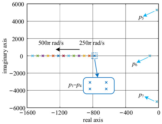
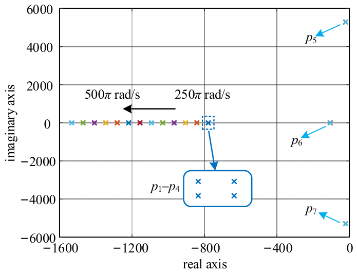
Figure 4 shows the pole movement trajectories plotted based on (20), which can be used for the stability analysis of the HOESO. The trajectories illustrate the movement of the poles as the bandwidth ω0 varies from 250π rad/s to 500π rad/s. As seen in the figure, since all the poles of the transfer function lie to the left of the real axis, the observer is stable. Moreover, as ω0 increases, the poles p1 to p4 consistently shift to the left. This movement enhances system stability and speeds up the response. However, excessive leftward pole displacement may amplify system noise.
Figure 4.
Pole distribution diagram of the proposed HOESO.
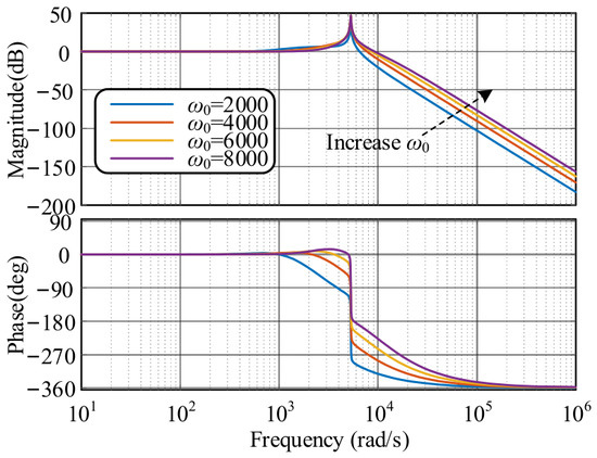
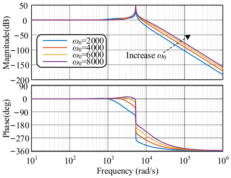
To investigate the influence of different ω0 values on the observation performance, the Bode plots of GE(s) are presented in Figure 5. It can be observed that the HOESO exhibits an overall low-pass filtering characteristic. Accurate BEMF estimation in terms of both amplitude and phase can be achieved only when ω0 is sufficiently higher than the motor operating frequency. However, increasing ω0 weakens the attenuation capability of the observer against high-frequency noise. Therefore, ω0 should be properly selected to achieve a tradeoff between fast tracking performance and high-frequency noise suppression.
Figure 5.
Bode diagram of the GE(s) with different ω0.
3.3. Performance of CCFAD Using Estimated Current
The equivalent block diagram of the LC-filtered PMSM current control loop is shown in Figure 6. Based on Figure 6, The formula for the system’s open-loop transfer function is
where Gp(s) = kp + ki/s, Gp(s) is the transfer function of the PI controller, kp is the proportional coefficient, and ki is the integral coefficient. GT(s) = 1/(1 + sTd), where Td is the delay time. Gf_L(s) = 1/(sLf), Gf_C(s) = 1/(sCf), Gm(s) = 1/(Rs + sLq).
Figure 6.
Equivalent block diagram of LC-filtered PMSM current control loop.
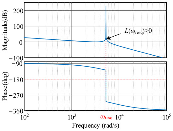
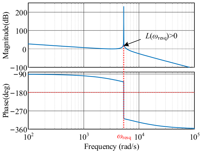
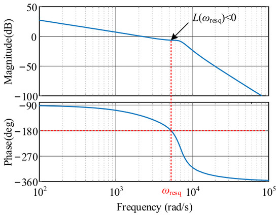
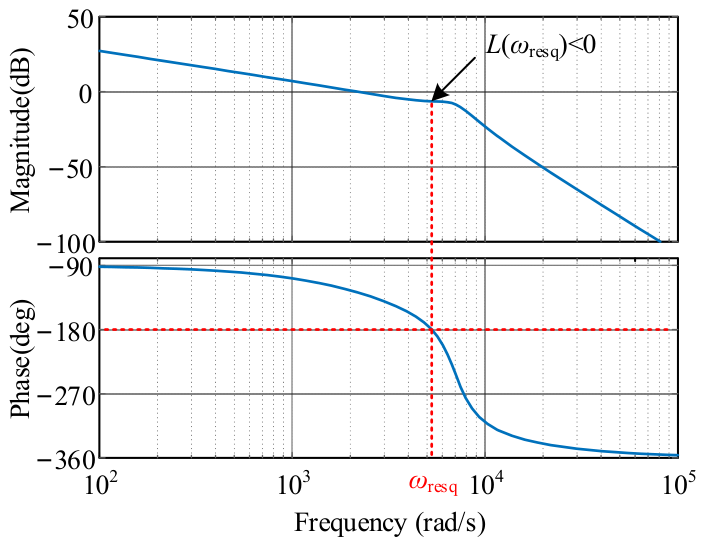
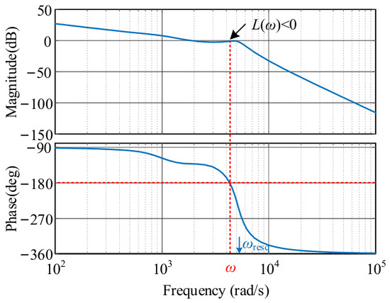
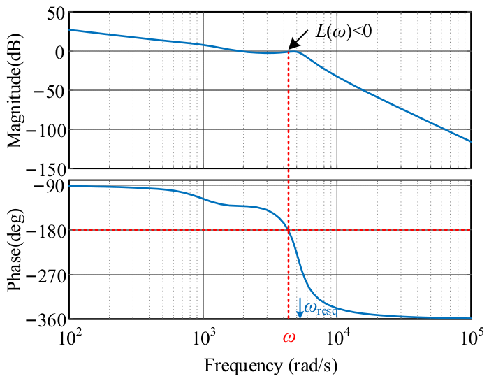
According to the transfer function in (21), the stator terminal resistance of the PMSM is neglected during the resonance analysis to represent the most severe undamped condition of the LC-filtered PMSM drive system [34]. Under this condition, the frequency response of the LC-filtered PMSM current-control loop is shown in Figure 7. The figure reveals a resonance peak in the magnitude-frequency response curve at the resonant frequency ωresq, significantly exceeding the 0 dB line. Correspondingly, the phase-frequency response curve crosses the -180° parallel line at this frequency. According to the Nyquist stability criterion, the closed-loop system of this current control loop is unstable.
Figure 7.
Frequency responses of LC-filtered PMSM current control loop.
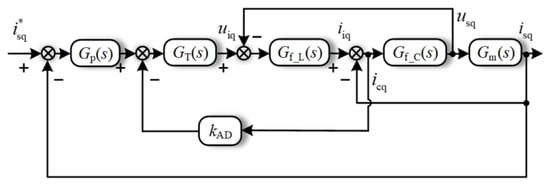
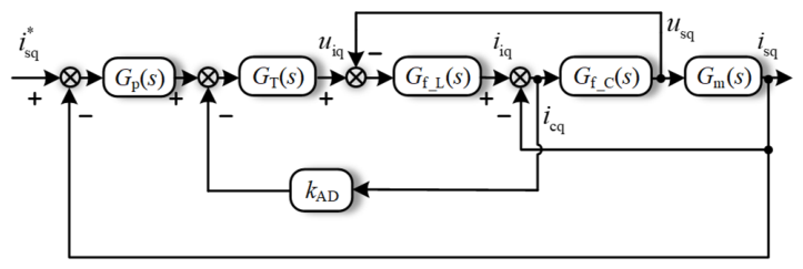
The AD method for suppressing resonance is considered simple and effective, particularly as CCFAD is widely adopted in the LC-filtered PMSM drive system. The equivalent block diagram of the current control loop based on CCFAD is shown in Figure 8.
Figure 8.
Equivalent block diagram of the current control loop based on CCFAD.
According to Figure 8, for the current loop with CCFAD, the open-loop transfer function is expressed as.
where kAD is the active damping coefficient. kAD can be calculated based on Lf, Lq and fres, as given by kAD = α(Lf + Lq)/Lq, where α = 1/(3 × 2πfresCf). The design of the d-axis parameters follows the same principle [35].
Based on the Bode diagram of the system’s open-loop transfer function from (22) shown in Figure 9, the figure indicates that the resonant peak has been reduced to below 0 dB. According to the Nyquist stability criterion, the system is stable. Therefore, suppressing resonance is essential to achieving stable operation of the LC-filtered PMSM drive system.
Figure 9.
Frequency responses of the current control loop based on CCFAD.
However, the implementation of CCFAD would ordinarily require an additional current sensor. Based on the HOESO designed above, precise estimation of the motor current can be achieved using only the inverter-side current sensor, thereby obtaining the capacitor current through subtraction to realize AD.
To verify the performance of the estimated current when it is fed back to the current control loop, the estimated motor current obtained from (10) is
According to (11), (13), and (23), the transfer functions relating the estimated motor current to the inverter-side current and voltage, as well as their linear combination relationship, can be derived as
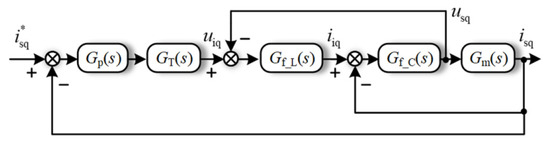
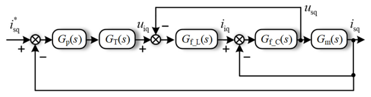
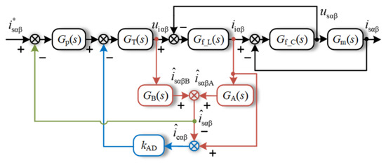
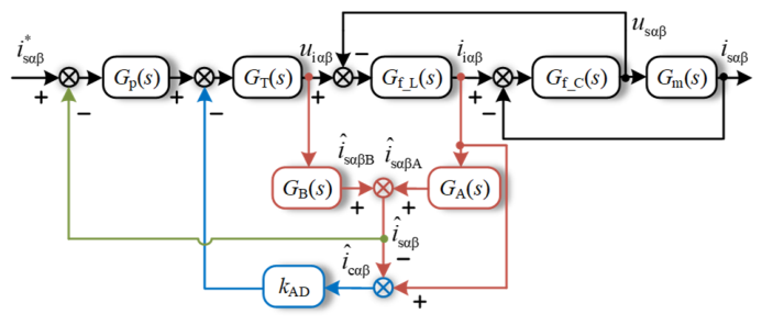
Figure 10 shows the equivalent block diagram of the current control loop with feedback based on the motor current estimated by the HOESO. Its open-loop transfer function can be expressed as
Figure 10.
Equivalent block diagram of the current control loop with estimated motor current.
Figure 11 shows the Bode diagram of the system’s open-loop transfer function plotted according to (27). Based on the Nyquist stability criterion, it can be concluded that using the estimated motor current to implement both the current-loop feedback and CCFAD in the LC-filtered PMSM drive system is stable.
Figure 11.
Frequency responses of the current control loop with estimated motor current.
3.4. SOGI-Based Differential Extraction
As indicated by (10), obtaining the estimated motor current and BEMF requires first- and second-order differential signals of the inverter-side voltage. However, increasing the bandwidth of the HOESO leads to the issue of noise amplification, which consequently increases the estimation error for both the current and the BEMF.
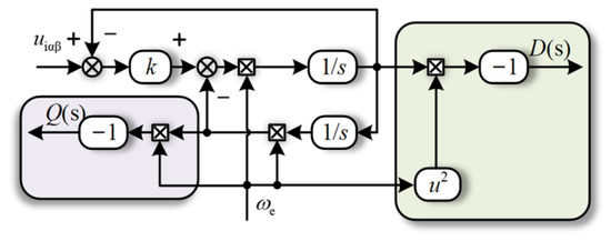
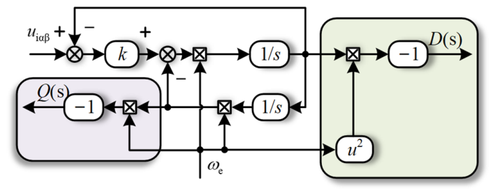
The structural block diagram for extracting differential signals using the SOGI is shown in Figure 12. The input signal can be decomposed by the SOGI into an in-phase component and a quadrature component. Therefore, the sinusoidal input signal uiαβ can be processed by the SOGI to obtain its first- and second-order differential components, thereby reducing the estimation error.
Figure 12.
Structural diagram for extracting differential signals using the SOGI.
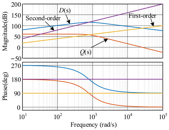
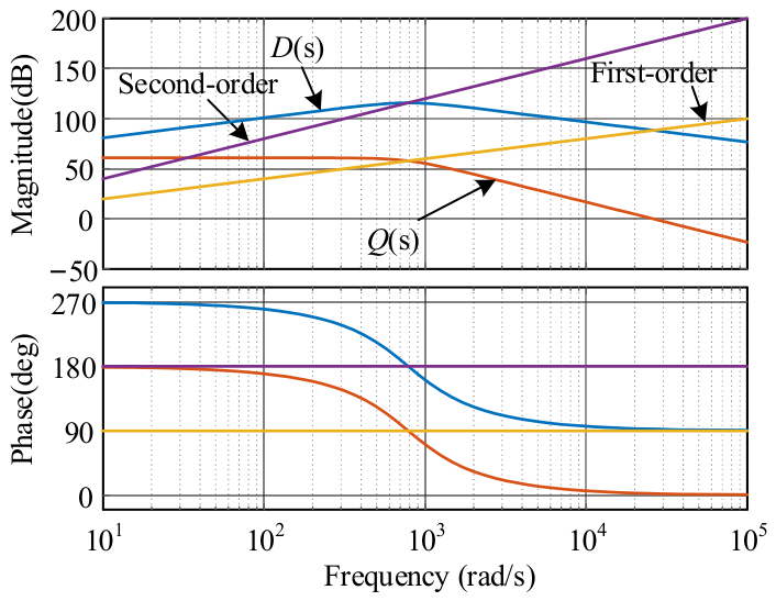
The transfer functions from the SOGI output for the second-order differential component D(s) and the first-order differential component Q(s) are given by
where k0 denotes the gain parameter and is set to 1.414 [36].
Figure 13 shows the frequency responses of D(s), Q(s), and the differentiator when the center frequency is ωe.
Figure 13.
Frequency response of different differential extraction methods.
As can be seen from Figure 13, direct differentiation further amplifies high-frequency noise, thereby degrading the estimation performance of the HOESO. In contrast, both the in-phase and quadrature outputs of the SOGI exhibit significant attenuation of high-frequency amplitudes. Using the SOGI to extract differential components can therefore effectively suppress high-frequency noise interference and improve the estimation performance of the HOESO.
3.5. Comparison with Existing Sensorless Methods for LC-Filtered Motor Drives
To further clarify the differences between the proposed method and existing studies, Table 1 compares representative sensorless control methods for LC-filtered motor drives. The comparison is conducted in terms of additional sensors, the current used for control feedback, the number of adjustable parameters, and tuning complexity. It can be seen that some existing methods require additional motor-side voltage or current sensors, which increase the hardware cost and limit their applicability in long-cable drive systems. Although several methods avoid additional sensors, the inverter-side current is directly used for control feedback. Due to the voltage drop, phase delay, and resonance introduced by the LC filter, the inverter-side current cannot accurately represent the motor-side current, which may degrade the control performance. In contrast, the proposed SOGI-assisted HOESO estimates the motor-side current without additional motor-side sensors and uses it for control feedback. Moreover, the observer gains can be tuned by only one bandwidth parameter, which significantly reduces the tuning complexity compared with other full-order observer-based methods.
Table 1.
Comparison of the proposed SOGI-assisted HOESO with existing sensorless methods for LC-filtered motor drives.
4. Experimental Validation
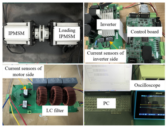
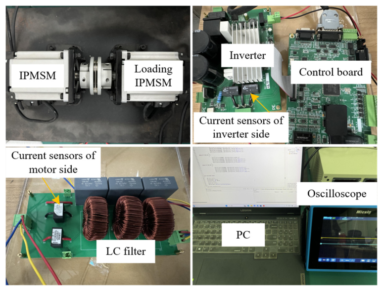
Figure 14 shows the experimental platform of the LC-filtered IPMSM drive system. The IPMSM is the tested motor controlled by the proposed sensorless control strategy. The loading IPMSM is mechanically coupled with the tested IPMSM and is used to provide load torque during the experiments. The inverter converts the DC-link voltage into three-phase Pulse Width Modulation (PWM) voltages according to the control signals generated by the control board. The LC filter is connected between the inverter and the tested IPMSM to suppress the high-frequency components of the inverter output voltage and generate a nearly sinusoidal motor-side voltage.
Figure 14.
Test platform.
The current sensors of the inverter side are used to measure the inverter-side currents, which are the actual current inputs of the proposed SOGI-assisted HOESO and control algorithm. The current sensors on the motor side are installed only for experimental evaluation so that the estimated motor-side current can be compared with the measured motor-side current. They are not used in the actual sensorless control loop. The overall control algorithm is implemented on a control board based on the TMS320F28335 DSP. The necessary system parameters are presented in Table 2.
Table 2.
Main parameters of the system.
4.1. Performance Analysis of the SOGI-Assisted HOESO
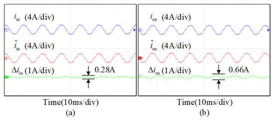
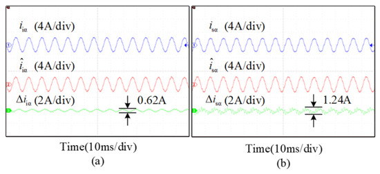
The estimation performance of the proposed SOGI-assisted HOESO can be analyzed based on the experimental results shown in Figure 15, Figure 16, Figure 17 and Figure 18. To evaluate the accuracy of the motor current and the position information contained in the BEMF, the first-order and second-order differential signals used in this section are those extracted by the SOGI.
Figure 15.
Experimental results of estimated variables of HOESO at 600 rpm. (a) Actual and estimated inverter-side current and their error. (b) Actual and estimated motor-side current and their error.
Figure 16.
Experimental results of estimated variables of HOESO at 1200 rpm. (a) Actual and estimated inverter-side current and their error. (b) Actual and estimated motor-side current and their error.
Figure 17.
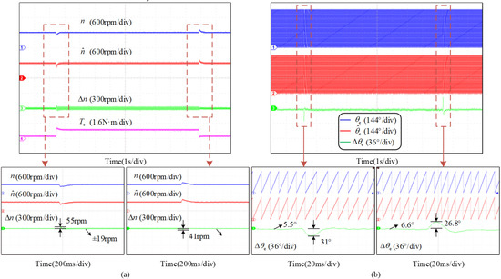
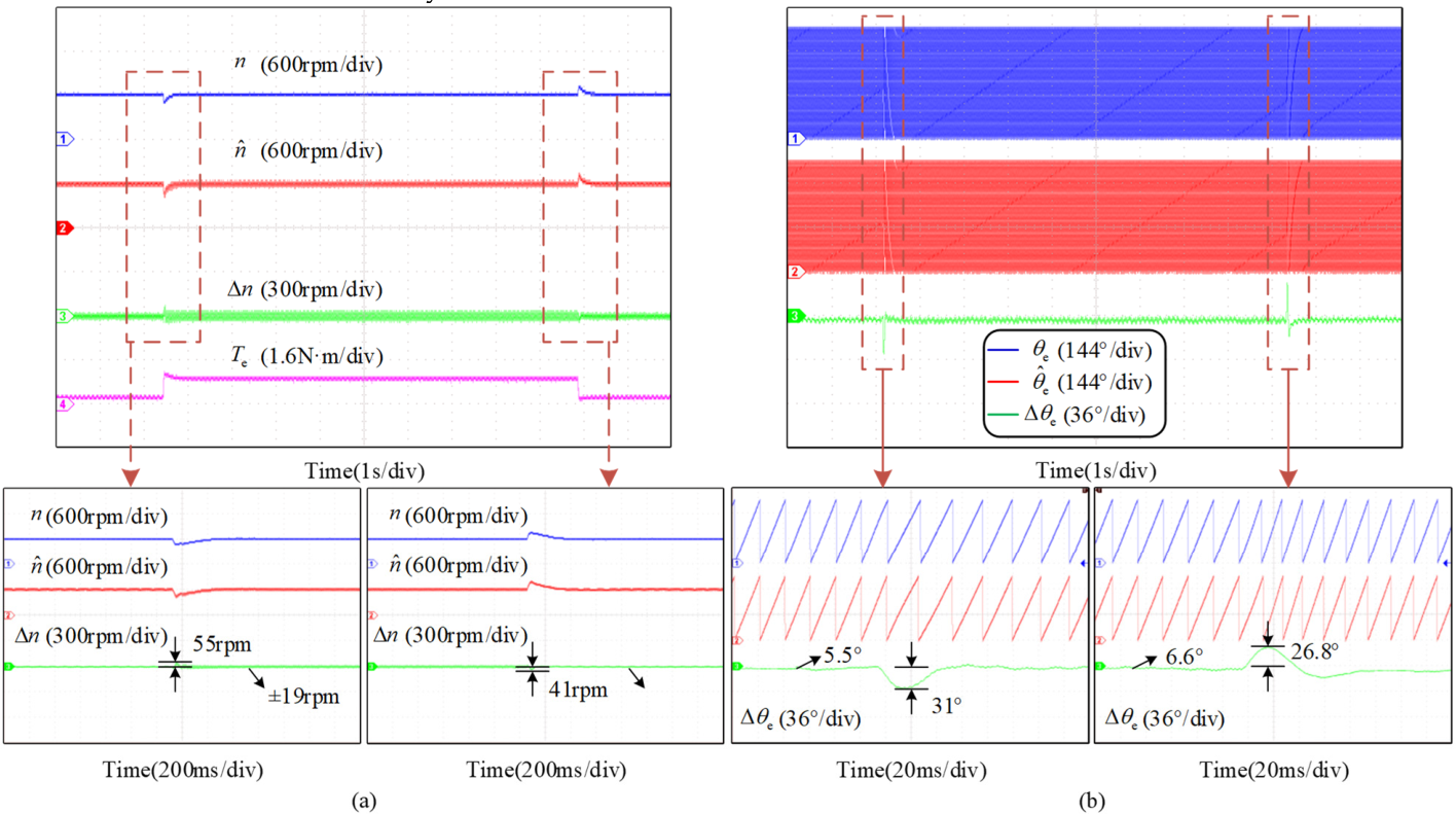
Experimental results of the rotor speed and position under the step load disturbance at 600 rpm. (a) Actual and estimated motor speed, speed error and torque. (b) Actual and estimated position and their error.
Figure 18.
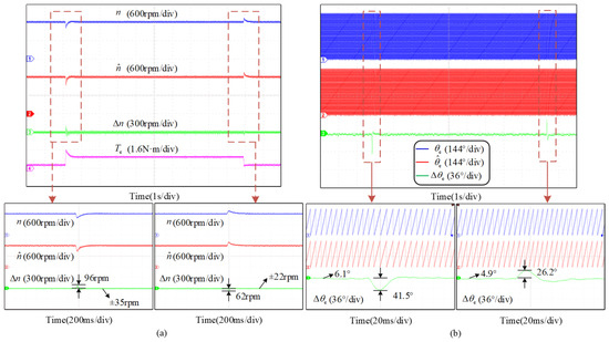
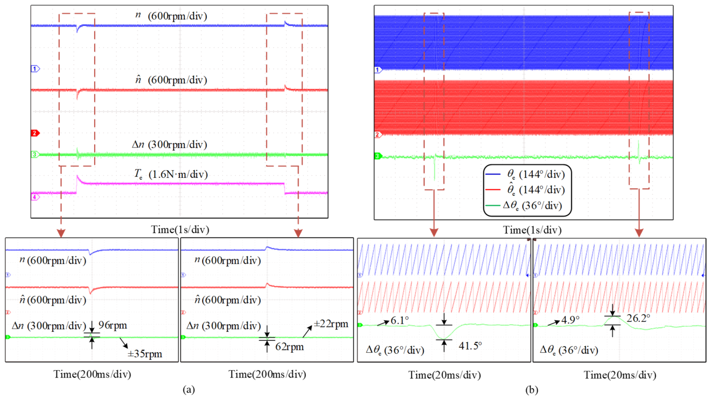
Experimental results of the rotor speed and position under the step load disturbance at 1200 rpm. (a) Actual and estimated motor speed, speed error and torque. (b) Actual and estimated position and their error.
Figure 15 and Figure 16 respectively illustrate the current estimation performance of the HOESO at speeds of 600 rpm and 1200 rpm under the 0.8 N·m step load. Figure 15a and Figure 16a demonstrate that the estimated inverter-side currents are nearly identical to the actual currents under steady-state conditions, with maximum estimation errors of 0.28 A and 0.62 A, respectively. Figure 15b and Figure 16b indicate that the estimated motor-side currents are also nearly identical to the actual currents under steady-state conditions, with maximum estimation errors of 0.66 A and 1.24 A, respectively. Consequently, the proposed SOGI-assisted HOESO exhibits precise current estimation capability.
Figure 17 and Figure 18 show the experimental waveforms of the motor responding to a 0.8 N·m step load at different speeds.
As can be seen from Figure 17a, when the motor operates steadily at 600 rpm, the estimated speed is nearly identical to the actual speed, with the estimation error remaining within ±12 rpm. The deviation between the two is minimal, with no significant oscillation, indicating that the motor maintains stable operation. Upon the application of the 0.8 N·m load step, the maximum speed estimation error reaches 55 rpm, and under loaded operation, the speed estimation error fluctuates within ±19 rpm. When the load is removed, the maximum speed estimation error reaches 41 rpm, after which the motor returns to a steady operating state. Figure 17b shows how the estimated rotor position error responds to a load transient at 600 rpm. It can be clearly observed from the figure that during the motor loading and unloading process, the estimated rotor position error reaches a maximum of 31° but quickly recovers to within 6.6°, with no significant abrupt error variations. The estimated rotor position error remains relatively stable with high accuracy.
As can be observed from Figure 18, when the motor operates steadily at 1200 rpm, both the estimated speed error and the estimated rotor position error remain within acceptable ranges. This indicates that the proposed method can maintain stable operation under load disturbances.
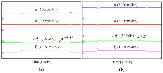
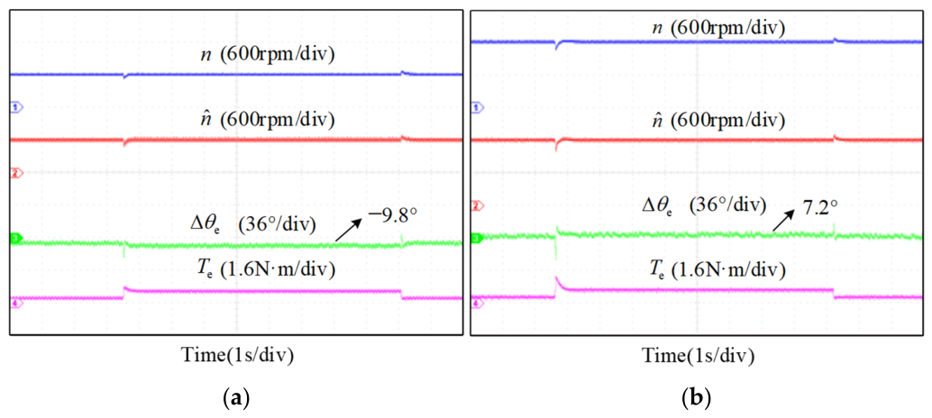
Figure 19 shows the experimental waveforms of the motor responding to a 0.4 N·m step load at different speeds. As can be seen from the figure, the estimated speed closely matches the actual speed, and the maximum rotor position error remains at around 10° during steady-state operation.
Figure 19.
Experimental results of actual rotor speed, estimated rotor speed, and position estimation error under the step load disturbance at (a) 600 rpm. (b) 1200 rpm.
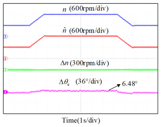
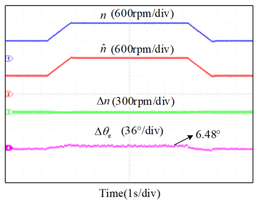
Figure 20 shows the experimental results for the actual speed, estimated speed, speed estimation error, and position estimation error during continuous speed variation under no-load conditions, with the speed reference varying between 600 and 1200 and 600 rpm. As can be seen from the figure, the speed estimation error remains near 0 rpm, and the maximum rotor position estimation error is only 6.48°. The system exhibits good steady-state and dynamic performance.
Figure 20.
Experimental results of actual rotor speed, estimated rotor speed, speed estimation error and position estimation error during continuous speed variation.
4.2. Comparative Analysis of Differential Extraction Based on SOGI
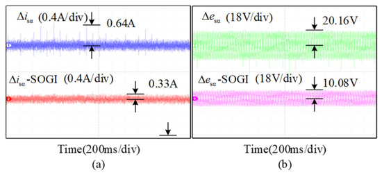
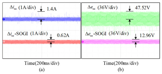
Figure 21 and Figure 22 present comparative experimental waveforms of the motor current estimation error and BEMF estimation error when differentials extracted by the SOGI are used, compared with direct differentiation, at motor speeds of 600 rpm and 1200 rpm, respectively.
Figure 21.
Comparative experimental results based on SOGI differential extraction at 600 rpm. (a) Motor current estimation error. (b) BEMF estimation error.
Figure 22.
Comparative experimental results based on SOGI differential extraction at 1200 rpm. (a) Motor current estimation error. (b) BEMF estimation error.
Figure 21a and Figure 22a reveal that direct differentiation introduces spikes into the motor current estimation error, resulting in maximum errors of 0.64 A and 1.4 A, respectively. In contrast, the maximum motor current estimation errors using SOGI-extracted differentiation were 0.33 A and 0.62 A. The obtained results verify the capability of the proposed strategy to mitigate high-frequency noise interference and achieves higher estimation accuracy.
Figure 21b and Figure 22b show that direct differentiation caused maximum BEMF estimation errors of 20.16 V and 47.54 V, respectively. In contrast, the maximum BEMF estimation errors using SOGI-extracted differentials were 10.08 V and 12.96 V. This consequently reduces the estimated rotor position error, demonstrating that the proposed SOGI-assisted HOESO sensorless drive strategy achieves superior control performance.
4.3. Harmonic Analysis of Motor-Side Current
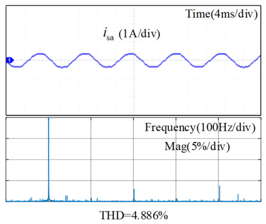
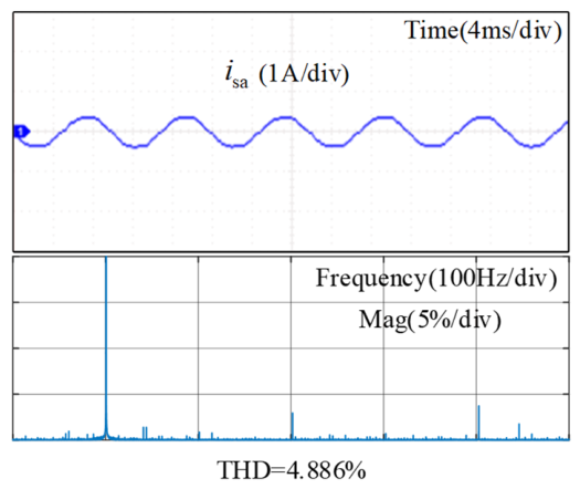
To further evaluate the current quality of the LC-filtered PMSM drive system, harmonic analysis is performed on the measured motor-side phase-A current isa. Figure 23 shows the current waveform and its Fast Fourier Transform (FFT) spectrum under the 1200 rpm and 0.8 N·m loaded condition. The FFT analysis is conducted using the steady-state current after the load transient.
Figure 23.
FFT analysis of the motor-side phase-A current.
As shown in Figure 23, the measured motor-side phase current maintains a nearly sinusoidal waveform. In the frequency spectrum, the fundamental component is dominant, whereas the high-frequency harmonic components are relatively small. The corresponding total harmonic distortion (THD) value is 4.886%. This result indicates that the motor-side current has low harmonic distortion under the LC-filtered drive system.
The LC filter plays an important role in this process. Since the inverter output voltage contains high-frequency PWM switching harmonics, directly applying this voltage to the motor may increase current harmonics, motor losses, insulation stress, and electromagnetic interference. By inserting the LC filter between the inverter and the motor, the high-frequency switching components can be attenuated, and a nearly sinusoidal motor-side voltage can be obtained. Therefore, the motor-side current quality can be improved. Although the LC filter increases the system order and introduces resonance, the proposed SOGI-assisted HOESO and CCFAD strategy ensures stable current control and maintains low motor-current THD.
5. Conclusions
This paper addresses the challenges of resonance and increased system order introduced by LC sine-wave filters, proposing a sensorless control strategy based on a SOGI-assisted HOESO. This method requires only the inverter-side currents to achieve high-precision simultaneous observation of motor currents and BEMF, significantly reducing system cost. Furthermore, the proposed HOESO structure allows for parameter tuning merely through bandwidth adjustment. By utilizing the differential signals extracted by the SOGI, high-frequency noise is effectively suppressed, enhancing observation accuracy.
Experimental results verify the effectiveness of the proposed method. Under a 0.8 N·m step load at 600 rpm and 1200 rpm, the maximum motor-side current estimation errors are 0.66 A and 1.24 A, respectively. During continuous speed variation from 600 rpm to 1200 rpm and back to 600 rpm, the maximum rotor position estimation error is 6.48°, demonstrating good dynamic position estimation performance. Compared with direct differentiation, the SOGI-based differential extraction reduces the maximum BEMF estimation errors from 20.16 V and 47.54 V to 10.08 V and 12.96 V, respectively. Moreover, the FFT analysis of the measured motor-side phase-A current gives a THD of 4.886% at 1200 rpm under 0.8 N·m load, indicating that the LC-filtered drive system maintains good motor-side current quality under the proposed control strategy.
However, the observer bandwidth ω0 still needs to be selected as a compromise between fast tracking performance and high-frequency noise suppression. An excessively large bandwidth may amplify measurement noise, whereas a small bandwidth may reduce dynamic estimation performance.
Author Contributions
Conceptualization, S.C., Z.M., T.D.R. and X.W.; Methodology, S.C., Z.M., T.D.R. and X.W.; Software, S.C. and X.W.; Validation, S.C. and X.W.; Formal analysis, S.C. and X.W.; Investigation, S.C. and X.Z.; Resources, X.Z. and Y.L.; Data curation, X.Z. and Y.L.; Writing—original draft, X.Z.; Writing—review and editing, X.Z. and Y.L.; Visualization, Y.L., Z.M. and T.D.R.; Supervision, S.C., Y.L., Z.M. and T.D.R.; Funding acquisition, S.C. All authors have read and agreed to the published version of the manuscript.
Funding
This work was supported by the National Natural Science Foundation of China under Grant 62503481, the Basic Research Program of Jiangsu under Grant BK20251627 and the Fundamental Research Funds for Central Universities under Grant 2025QN1114, Shuo Chen.
Data Availability Statement
The original contributions presented in this study are included in the article. Further inquiries can be directed to the corresponding author.
Acknowledgments
The authors gratefully acknowledge the support and assistance received during the preparation of this manuscript.
Conflicts of Interest
On behalf of all authors, the corresponding author states that there is no conflict of interest.
Abbreviations
The following abbreviations are used in this manuscript:
| PMSM | permanent magnet synchronous motor |
| SOGI | second-order generalized integrator |
| HOESO | high-order extended state observer |
| BEMF | back electromotive force |
| CCFAD | capacitor current feedback active damping |
| VSI | voltage source inverter |
| EMC | electromagnetic compatibility |
| AD | active damping |
| PD | passive damping |
| IPMSM | Interior PMSM |
| PI | proportional-integral |
| SPMSMs | surface-mounted permanent magnet synchronous motors |
| IPMSMs | Interior Permanent Magnet Synchronous Motors |
| PLL | phase-locked loop |
| PD | phase detector |
| LF | loop filter |
| PWM | Pulse Width Modulation |
| FFT | Fast Fourier Transform |
| THD | total harmonic distortion |
References
- Zhang, G.; Li, S.; Li, B.; Wang, Q.; Wang, G.; Xu, D. Acoustic Noise Reduction Using Half-Period-Switching Pseudorandom Sinusoidal Injection with External Tangent Demodulation for Sensorless PMSM Drives. IEEE Trans. Transp. Electrif. 2025, 11, 5312–5323. [Google Scholar]
- Sun, X.; Zhang, S.; An, X.; Su, Z.; Li, F. A Robust DPCC and Inductance Identification Method for SPMSM Based on Incremental Model and Current Error Compensation. IEEE Trans. Ind. Electron. 2026, 73, 219–229. [Google Scholar]
- Cai, J.; Gu, Y.; Cheok, A.D.; Yan, Y. A Survey of Phase-Locked Loop Technologies in Sensorless Position Estimation of Permanent Magnet Synchronous Motor Drives. IEEE Trans. Instrum. Meas. 2024, 73, 1504016. [Google Scholar] [CrossRef] [Scilit]
- Li, S.; Cai, M.; Zhuo, L.; Kennel, R.; Heldwein, M.L.; Xu, Y. A Novel Constrained Offset-Free Model Predictive Position Controller for PMSM Drives with a Computationally Efficient Design. IEEE Trans. Power Electron. 2026, 41, 1774–1787. [Google Scholar] [CrossRef] [Scilit]
- Chen, S.; Ding, W.; Hu, R.; Wu, X.; Shi, S. Sensorless Control of PMSM Drives Using Reduced Order Quasi-Resonant-Based ESO and Newton–Raphson Method-Based PLL. IEEE Trans. Power Electron. 2023, 38, 229–244. [Google Scholar]
- Park, S.; Chin, T.; Lee, S.; Cho, Y. Leakage Current Analysis of Three-Phase Inverter Motor Drive System with Sine Wave Filter. J. Power Electron. 2024, 24, 1607–1616. [Google Scholar] [CrossRef] [Scilit]
- Xu, J.; Zhang, R.; Jia, P.; Zhang, M. Multivariable Feedback Damping Control of LC-Filtered PMSM for Resonance Suppression with Fast Dynamic Response. IEEE J. Emerg. Sel. Top. Power Electron. 2025, 13, 3618–3630. [Google Scholar] [CrossRef] [Scilit]
- Liu, X.; Peng, M.; Liu, J.; Cao, J.; Li, L. A Control Method for LC-Equipped High-Speed PMSM Based on Synchronous Coordinate Extended State Observer. IEEE Trans. Power Electron. 2026, 41, 3346–3359. [Google Scholar] [CrossRef] [Scilit]
- Wu, X.; Ji, Y.; Li, C.; Xu, Y.; Zou, J.; Tian, L. Review and New Expansion of the Active Damping Strategy of the PMSM Drive System with LC Sine Wave Filter. CES Trans. Electr. Mach. Syst. 2025, 9, 268–288. [Google Scholar] [CrossRef] [Scilit]
- Li, S.; Lin, H. A Capacitor-Current-Feedback Positive Active Damping Control Strategy for LCL-Type Grid-Connected Inverter to Achieve High Robustness. IEEE Trans. Power Electron. 2022, 37, 6462–6474. [Google Scholar]
- Wu, X.; Ji, Y.; Li, C.; Zhang, Y.; Chen, S.; Yang, J.; Han, Y. ESO–SOGI-Based Capacitor Current Feedback Active Damping for PMSM with LC Sine-Wave Filter Resonance Suppression. J. Power Electron. 2025, in press. [Google Scholar] [CrossRef] [Scilit]
- Wu, X.; Wu, B.; Chen, S.; Ding, W.; Ma, Z.; Han, Y. An Anti-DC Offset Interference Sensorless Control Method for PMSM Based on Improved SMO and MDCF-FPS-PLL. IEEE J. Emerg. Sel. Top. Power Electron. 2026, 14, 555–568. [Google Scholar] [CrossRef] [Scilit]
- Li, Y.; Yin, Z.; Yuan, D.; Zhang, Y.; Gao, Y.; Yang, H. A Multi-Harmonics Suppression Backstepping Extended State Observer for the PMSM Electrolytic Capacitorless Drives Sensorless Control. IEEE Trans. Power Electron. 2025, 40, 10769–10782. [Google Scholar]
- Liu, K.; Yang, W.; Jiao, L.; Yuan, Z.; Wen, C.-Y. Fast Fixed-Time Distributed Neural Formation Control-Based Disturbance Observer for Multiple Quadrotor UAVs Under Unknown Disturbances. IEEE Trans. Aerosp. Electron. Syst. 2025, 61, 13137–13155. [Google Scholar]
- Liu, K.; Wang, X.; Wang, R.; Sun, G.; Wang, X. Antisaturation Finite-Time Attitude Tracking Control Based Observer for a Quadrotor. IEEE Trans. Circuits Syst. II Express Briefs 2021, 68, 2047–2051. [Google Scholar]
- Cai, J.; Gu, Y.; Liu, Z.; Song, S. Cost-Function Extremum Seeking Based Model Predictive Torque Control of PMSM with Sensorless Position Estimation. IEEE Trans. Power Electron. 2025, 40, 17664–17673. [Google Scholar] [CrossRef] [Scilit]
- Chen, S.; Yu, X.; Wu, X.; Ding, W.; Chen, J.; Dai, X. A Novel Computationally Efficient Finite Position Set-Phase Locked Loop for Low-Speed Sensorless IPMSM Control. IEEE Trans. Power Electron. 2026, 41, 1562–1568. [Google Scholar]
- Mukherjee, S.; Poddar, G. Fast Control of Filter for Sensorless Vector Control SQIM Drive with Sinusoidal Motor Voltage. IEEE Trans. Ind. Electron. 2007, 54, 2435–2442. [Google Scholar] [CrossRef] [Scilit]
- Vaishnav, N.; Bajjuri, N.K.; Jain, A.K. Inductor Selection, Improved Active Damping, and Speed Sensorless Operation without Voltage Sensors in IM Drive with LC Filter. IEEE Trans. Power Electron. 2022, 37, 15272–15282. [Google Scholar] [CrossRef] [Scilit]
- Liu, J.; Nondahl, T.A.; Dai, J.; Royak, S.; Schmidt, P.B. A Seamless Transition Scheme of Position Sensorless Control in Industrial Permanent Magnet Motor Drives with Output Filter and Transformer for Oil Pump Applications. IEEE Trans. Ind. Appl. 2020, 56, 2180–2189. [Google Scholar] [CrossRef] [Scilit]
- Carbone, L.; Marchesoni, M.; Passalacqua, M.; Postiglione, G.; Vaccaro, L.; Vitaloni, C. Sensorless Control of Medium Voltage Induction Motor with LC Filter and Long Cable in Oil Pump Applications. IEEE Trans. Energy Convers. 2025, 40, 3–15. [Google Scholar] [CrossRef] [Scilit]
- Xue, C.; Wu, X.; Li, Y.; Li, Y. Virtual Reduced-Order Model-Based Back EMF Estimation and Speed Sensorless Control for LC-Filtered PMSM Drives. IEEE Trans. Power Electron. 2025, 40, 9749–9763. [Google Scholar] [CrossRef] [Scilit]
- Piippo, A.; Salomaki, J.; Luomi, J. Signal Injection in Sensorless PMSM Drives Equipped with Inverter Output Filter. IEEE Trans. Ind. Appl. 2008, 44, 1614–1620. [Google Scholar] [CrossRef] [Scilit]
- Wang, M.; Xu, Y.; Zou, J. Sliding Mode Control with Open-Switch Fault Diagnosis and Sensorless Estimation Based on PI Observer for PMSM Drive Connected with an LC Filter. IET Power Electron. 2020, 13, 2334–2341. [Google Scholar]
- Xu, Y.; Wang, M.; Zhang, W.; Zou, J. Sliding Mode Observer for Sensorless Control of Surface Permanent Magnet Synchronous Motor Equipped with LC Filter. IET Power Electron. 2019, 12, 686–692. [Google Scholar] [CrossRef] [Scilit]
- Wu, X.; Li, C.; Zhang, Y.; Chen, S.; Ma, Z.; Han, Y.; Zhang, X.; Tan, G. Sensorless Control of IPMSM Equipped with LC Sinusoidal Filter Based on Full-Order Sliding Mode Observer and Feedforward QPLL. IEEE Trans. Power Electron. 2024, 39, 8072–8085. [Google Scholar] [CrossRef] [Scilit]
- Swamy, M.M.; Kang, J.-K.; Shirabe, K. Power Loss, System Efficiency, and Leakage Current Comparison Between Si IGBT VFD and SiC FET VFD with Various Filtering Options. IEEE Trans. Ind. Appl. 2015, 51, 3858–3866. [Google Scholar] [CrossRef] [Scilit]
- Mishra, P.; Maheshwari, R. Design, Analysis, and Impacts of Sinusoidal LC Filter on Pulsewidth Modulated Inverter Fed-Induction Motor Drive. IEEE Trans. Ind. Electron. 2020, 67, 2678–2688. [Google Scholar]
- Zhang, Y.; Yin, Z.; Bai, C.; Wang, G.; Liu, J. A Rotor Position and Speed Estimation Method Using an Improved Linear Extended State Observer for IPMSM Sensorless Drives. IEEE Trans. Power Electron. 2021, 36, 14062–14073. [Google Scholar] [CrossRef] [Scilit]
- Xu, J.; Jia, P.; Zhang, R.; Zhang, M. Active Damping for LC-Filtered PMSM Based on Low-Pass Filter Capacitor Current Feedback and Extended State Observer. IEEE Trans. Transp. Electrif. 2024, 10, 3292–3304. [Google Scholar]
- Cui, Y.; Yin, Z.; Luo, P.; Yuan, D.; Liu, J. Linear Active Disturbance Rejection Control of IPMSM Based on Quasi-Proportional Resonance and Disturbance Differential Compensation Linear Extended State Observer. IEEE Trans. Ind. Electron. 2024, 71, 11910–11924. [Google Scholar] [CrossRef] [Scilit]
- Wang, G.; Li, Z.; Zhang, G.; Yu, Y.; Xu, D. Quadrature PLL-Based High-Order Sliding-Mode Observer for IPMSM Sensorless Control with Online MTPA Control Strategy. IEEE Trans. Energy Convers. 2013, 28, 214–224. [Google Scholar]
- Zhang, G.; Yan, Y.; Wang, Q.; Ding, D.; Wang, G.; Ding, L. Adaptive Step-Size Predictive PLL-Based Rotor Position Estimation Method for Sensorless IPMSM Drives. IEEE Trans. Power Electron. 2024, 39, 6136–6147. [Google Scholar]
- Lyu, Z.; Wu, L. Resonant Frequency Deviation Analysis and Modified Notch Filter-Based Active Damping for SiC-Based PMSM Drive with Sine Wave Filter. IEEE Trans. Energy Convers. 2023, 38, 417–427. [Google Scholar]
- Ben Saïd-Romdhane, M.; Naouar, M.W.; Slama-Belkhodja, I.; Monmasson, E. Robust Active Damping Methods for LCL Filter-Based Grid-Connected Converters. IEEE Trans. Power Electron. 2017, 32, 6739–6750. [Google Scholar]
- Wu, X.; Wu, B.; Li, J.; Lu, S.; Li, C.; Li, J.; Yue, H.; Zhang, X. SOGI-Based Finite Position Set-Phase Locked Loop for Sensorless Control of PMSMs. J. Power Electron. 2026, 26, 77–87. [Google Scholar]

Disclaimer/Publisher’s Note: The statements, opinions and data contained in all publications are solely those of the individual author(s) and contributor(s) and not of MDPI and/or the editor(s). MDPI and/or the editor(s) disclaim responsibility for any injury to people or property resulting from any ideas, methods, instructions or products referred to in the content. |
© 2026 by the authors. Licensee MDPI, Basel, Switzerland. This article is an open access article distributed under the terms and conditions of the Creative Commons Attribution (CC BY) license.