


Abstract
Natural fractures can significantly affect fluid seepage behavior and development performance in tight formations. However, the optimal configurations and performance of oriented horizontal wells under various natural fracture scenarios remain insufficiently understood. Numerical simulation models for a fractured horizontal well in a five-spot well pattern were established based on the embedded discrete fracture model (EDFM) to consider the coupled effects of hydraulic fractures and natural fractures. Optimization analyses were performed under different natural fracture conditions, with cumulative oil production used as the main evaluation criterion. The results indicate that natural fractures play a significant role in determining the optimal horizontal well orientation. For reservoirs without natural fractures and those with low- to medium-density single-set natural fractures, the optimal horizontal well orientation is perpendicular to the maximum horizontal stress direction. In contrast, for high-density single-set natural fracture systems, a slight rotation of the horizontal wellbore improves cumulative oil production, with an optimal orientation angle of approximately 15° identified in this work. For conjugate fracture networks, the influence of well orientation becomes more significant, and the optimal orientation angle varies with fracture density, ranging from 15° to 45°. This study indicates that the horizontal wellbore trajectory design may highly rely on the characteristics of natural fractures. Therefore, thorough and accurate characterization of natural fractures should be conducted before optimizing the orientation of fractured horizontal wells. The findings of this work provide theoretical guidance for the placement of fractured horizontal wellbores in naturally fractured tight formations.
1. Introduction
High-permeability channels, including natural fractures and hydraulic fractures, play a significant role in enhancing hydrocarbon production from unconventional reservoirs, particularly in low-permeability formations such as tight sandstone and shale reservoirs [1]. In these tight formations, fracture networks composed of natural and hydraulic fractures dominate fluid flow within reservoirs and substantially alter pore connectivity and permeability anisotropy [2,3,4]. Laboratory and field evidence also shows that well production performance can be strongly controlled by fracture geometry, fracture density, and the orientation relationship between the stress field and the wellbore trajectory [5,6,7]. However, the optimal orientation of horizontal wells under different fracture systems remains unclear and should account for both natural and hydraulic fractures.
Modeling fluid flow in fractured reservoirs is challenging because of the significant difference between fracture scale and reservoir scale. To address the multiscale characteristics of fractured reservoirs, dual-porosity and dual-permeability models have been proposed [8,9], in which fractures are assumed to be evenly distributed within the reservoir. These continuum approaches can greatly reduce computational cost but often fail to explicitly characterize fracture geometry and properties [10,11]. Meanwhile, dual-medium models may produce considerable calculation errors, especially in cases with relatively low fracture density, where the assumption of uniformly distributed fractures is not valid [11]. To explicitly characterize fracture networks, discrete fracture network (DFN) models have been introduced. This method treats grid boundaries as fractures and neglects fracture width, which can improve the rationality of the numerical models for discrete fracture networks [10,11]. However, the DFN method often suffers from mesh-generation difficulties when handling large-scale fractures. Computational cost also becomes a critical issue when abundant meshes are generated for field-scale cases with a large number of fractures [11,12]. To address the fracture characterization and computational cost, the embedded discrete fracture model (EDFM) has been developed, which can explicitly represent fractures in a structured or unstructured grid system [13,14,15,16]. The EDFM enables fracture grids to be embedded into existing matrix grids without requiring mesh conformity, thereby significantly reducing mesh-generation difficulties [15,17]. Moreover, the EDFM can simulate the fluid flow in fractured reservoirs with high fracture density while maintaining favorable computational efficiency [18]. Therefore, the EDFM has become a prevalent and efficient method to deal with fluid flow problems in fractured reservoirs.
Horizontal well drilling and hydraulic fracturing technologies can greatly enhance the seepage capacity and make production from tight formations viable [19,20]. Traditionally, the well trajectory is arranged along the minimum horizontal stress direction, resulting in induced hydraulic fractures perpendicular to the wellbore [21]. This design is closely related to the initiation and propagation behavior of hydraulic fractures, because the breakdown pressure during hydraulic fracturing is controlled by the in situ stress state, borehole size, and fracture-mechanics size effects [22]. Field practice and experimental results demonstrate the rationality of this design, which can achieve favorable development performance [23,24]. Nevertheless, few efforts have been made to investigate the effect of well orientation on production performance for injection–production systems in reservoirs containing discrete natural fractures. Given that induced hydraulic fractures may dominate the hydraulic connectivity and govern reservoir sweep efficiency, well orientation is a critical parameter that requires in-depth analysis and optimization to maximize the reservoir development performance [25,26]. Several studies have been conducted to optimize the wellbore placement in anisotropic fractured reservoirs [27,28,29]. However, most existing works are limited to simplified anisotropy or sparse fracture systems. Few studies have considered complex natural fracture networks. The coupled effects of natural fractures and induced hydraulic fractures under practical conditions also remain poorly understood.
Natural fracture networks often exhibit complicated morphologies caused by diverse tectonic conditions [30]. For instance, typical fracture distribution patterns commonly observed in practice include parallel fractures and intersecting fractures, such as conjugate or orthogonal fractures [31,32]. In particular, conjugate fracture networks can result in strong directional permeability anisotropy, making well orientation design far more complicated. Experimental and field observations demonstrate that sweep efficiency and production performance in fractured reservoirs with different natural fracture patterns may vary dramatically [18,33]. Recent works have been made to emphasize the importance of well placement optimization in naturally fractured reservoirs. Sherratt et al. optimized well orientation for hydraulic fracturing in shale gas formations with natural fractures [25], while Bagherinezhad et al. examined well placement and water breakthrough behavior in naturally fractured reservoirs [28]. Coupled StoSAG and the EDFM for well placement optimization in fractured reservoirs have also been proposed, demonstrating the potential of EDFM-based optimization frameworks [29]. However, most existing studies focus on simplified fracture systems, lack systematic consideration of natural fracture density variations, and rarely address conjugate fracture networks. Despite previous studies, quantitative analysis of optimal well orientation under various fracture systems remains limited.
To address the aforementioned challenges, this work adopted the EDFM to investigate the effects of natural fracture pattern and density on optimal well orientation. Three typical scenarios were considered in this work: reservoirs without natural fractures, reservoirs with one set of parallel natural fractures, and reservoirs with conjugate fracture networks. Analyses were conducted to investigate the influence of fracture density, orientation, and connectivity on sweep efficiency and production performance. This work can enhance understanding of the seepage and sweep mechanisms in complex fracture systems and contribute to rational wellbore trajectory design under complicated geological conditions.
2. Methodology
In this work, a five-spot well pattern consisting of one fractured horizontal production well and four injection wells was considered in a box-shaped reservoir. The main assumptions are summarized as follows:
- (1)
- The reservoir is assumed to be a homogeneous, horizontally layered formation with uniform permeability;
- (2)
- The well pattern is a typical five-spot pattern, with four vertical injectors at the corners and one horizontal producer at the center;
- (3)
- Natural fractures are represented by multiple discrete fractures, where fracture orientation and density are independent parameters used to define different fracture scenarios;
- (4)
- The hydraulic fractures have identical spacing and half-length, ensuring uniform properties in all stages;
- (5)
- The hydraulic fractures extend along the maximum horizontal principal stress direction, which is along the x-axis in this work;
- (6)
- The black-oil model is adopted to model the fluid properties, where reservoir fluids are represented by pseudo-components and pressure-dependent PVT properties are used to describe the phase behavior;
- (7)
- The injection wells have a fixed injection rate, with a maximum injection pressure limit; the production well has a prescribed production rate, with a minimum allowable bottom-hole pressure limit.
2.1. Governing Equations for Fractured Reservoirs with the EDFM
2.1.1. Fluid Flow Model
The governing equations for the fluid flow in the fractured reservoirs can be written as follows [15],
with the following auxiliary equations,
where t is the time; ϕ is the porosity; ρα is the density of phase α, where α = o, w refers to oil and water, respectively; Sα is the saturation of phase α; k is the permeability; krα is the relative permeability for phase α; μα is the phase viscosity; pα is the phase pressure; g is the gravitational acceleration; z is the depth; qα,w denotes the well source/sink term; and pcow is the capillary pressure.
2.1.2. Two-Point Flux Approximation (TPFA) Method
The finite volume method is then applied to discretize the governing equations, and the two-point flux approximation (TPFA) method is adopted to calculate the flow rate between two connected grids [15,16].
where qα,ij denotes the volumetric flow rate from grid j to grid i for phase α, and Tij is the transmissibility factor between grids j and i.
For the EDFM, the discretized fracture grids will be embedded into the matrix grids. The flow rate between the fracture grids and the matrix grids is handled by the transmissibility factor for non-neighboring connections (NNCs) if they are physically connected. Therefore, four types of transmissibility factor calculations are encountered in the EDFM: connections between connected matrix grids, connections between connected fracture grids, connections between a matrix grid and a fracture grid, and connections for intersecting fracture grids.
For the first two connection types described above, the transmissibility factor can be calculated by the following formulas [15,17],
where Tij is the transmissibility factor between grids i and j, Ti is the half-transmissibility for grid i, Aij is the interface area between grids i and j, ki is the permeability of grid i, and di refers to the distance from the grid center to the interface center.
For the NNCs between a fracture grid and its host matrix grid, the transmissibility factor can be written as
where Af is the fracture grid area, km is the matrix permeability, dmf is the average normal distance between the matrix and fracture grid, xn is the distance between point x and the fracture plane, and V is the matrix grid volume.
For intersecting fracture grids, the star-delta transformation approach is adopted, and the transmissibility factor between multiple intersecting fracture grids can be obtained as follows [16],
where Tfi is the half-transmissibility of the fracture grid i, wfi is the fracture width, Lint is the length of the intersection line for the connected fractures, and dfi is the distance from the fracture center to the intersection line.
With the processing method described above, hydraulic fractures and natural fractures can be explicitly represented using the EDFM approach. These fractures are treated as highly conductive flow domains embedded within the matrix domain. For the discretized grid system, the physically connected grids may not be connected in the computational domain. Flow between such physically connected grids can be readily handled using NNCs and the corresponding transmissibility factors.
The EDFM used in this work is a mature numerical framework for fractured-reservoir simulation. Therefore, only the main governing equations and transmissibility calculations are summarized here, while detailed discretization procedures for matrix–matrix, matrix–fracture, and fracture–fracture connections can be found in our previous work [15].
2.2. Fracture Representation in the EDFM
2.2.1. Hydraulic Fracture System
In this work, hydraulic fractures generated during multi-stage fracturing treatment were explicitly represented by the EDFM. As mentioned above, the discrete hydraulic fractures were embedded into their host matrix grids without requiring local grid refinement or grid conformity near the fractures. This approach can significantly improve the computational efficiency while maintaining high accuracy during fluid flow simulation in fractured reservoirs.
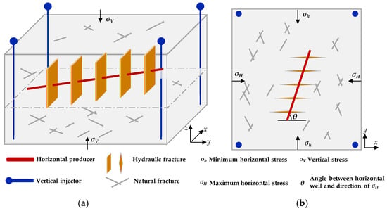
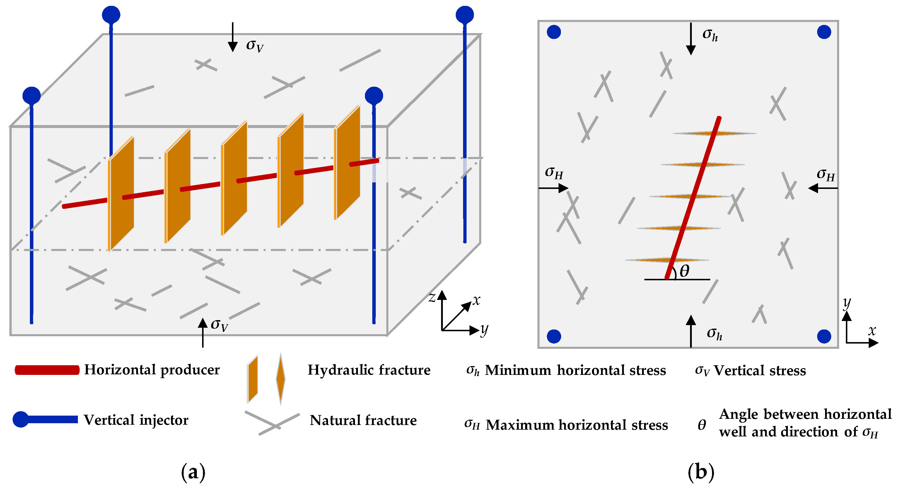
During the hydraulic fracturing process, hydraulic fractures propagate parallel to the direction of maximum horizontal stress σH (as shown in Figure 1b). In this work, the induced hydraulic fractures after hydraulic fracturing treatment were assumed to propagate along the x-axis, consistent with the fracture propagation mechanism mentioned above. In field practice, horizontal wells are generally drilled along the minimum horizontal stress direction (i.e., perpendicular to the direction of σH). Accordingly, the hydraulic fractures generated during subsequent hydraulic fracturing are perpendicular to the horizontal wellbore. Such a conventional wellbore trajectory design can provide favorable well production performance. However, it may not be optimal for formations with well-developed natural fractures. Therefore, this work investigated the effect of well orientation angle on well production performance. The distribution of induced hydraulic fractures may vary with well orientation angle, whereas their propagation directions remain consistent with the aforementioned propagation rule.
Figure 1.
Schematic diagrams illustrating the spatial arrangement of vertical injection wells and fractured horizontal wells: (a) 3D view; (b) plan view.
The main concern of this work is to investigate the optimal well orientation angle. All hydraulic fractures were assumed to have identical geometric and petrophysical properties, including fracture half-length, aperture, height, porosity, and conductivity. This assumption eliminates the effect of fracture heterogeneity and allows the analysis to focus on the influence of well orientation angle on well production performance under different natural fracture conditions. Further work will optimize well orientation design by considering the combined effects of hydraulic fracture heterogeneity and the natural fracture properties.
It should be noted that the hydraulic fracture propagation during stimulation was not explicitly simulated in this work. Instead, the post-fracturing fracture geometry was predefined according to the assumed propagation direction and fracture parameters.
2.2.2. Natural Fracture System
In this work, natural fracture networks were characterized using a discrete fracture network model based on stochastic statistical laws. Natural fractures (NFs) in tight formations show pronounced stochasticity and strong heterogeneity. Therefore, statistical parameters of the NFs, including the fracture azimuth, fracture length, fracture aperture, and fracture density, were selected to generate and characterize the natural fractures. Particularly, the stochastic nature of the NFs was represented by assigning statistical distributions to fracture azimuth and fracture length. The mean values and variances of these parameters were used to define the corresponding fracture distributions and properties. Moreover, fractured density was adopted to characterize the development degree of NFs within the reservoirs.
The natural fracture density was calculated based on the following formula:
where P1f is the fracture density, N is the number of natural fracture center points, and A is the area of the reservoir.
Based on the above statistical approach, a stochastic natural fracture generation algorithm was established. Various stochastic NF scenarios can be generated by changing the aforementioned key parameters. This method can be readily used to generate either single-set parallel fractures or intersecting fractures consistent with geological observations. For intersecting NFs, conjugate fracture distributions, which are commonly observed in real tight formations, were used in this work. The single-set fracture network was used to represent NFs with preferential orientation, whereas the conjugate fracture network was adopted to characterize multiple NF sets under complicated in situ stress conditions.
3. Model Setup
3.1. Simulation Model Description
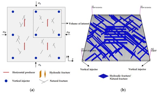
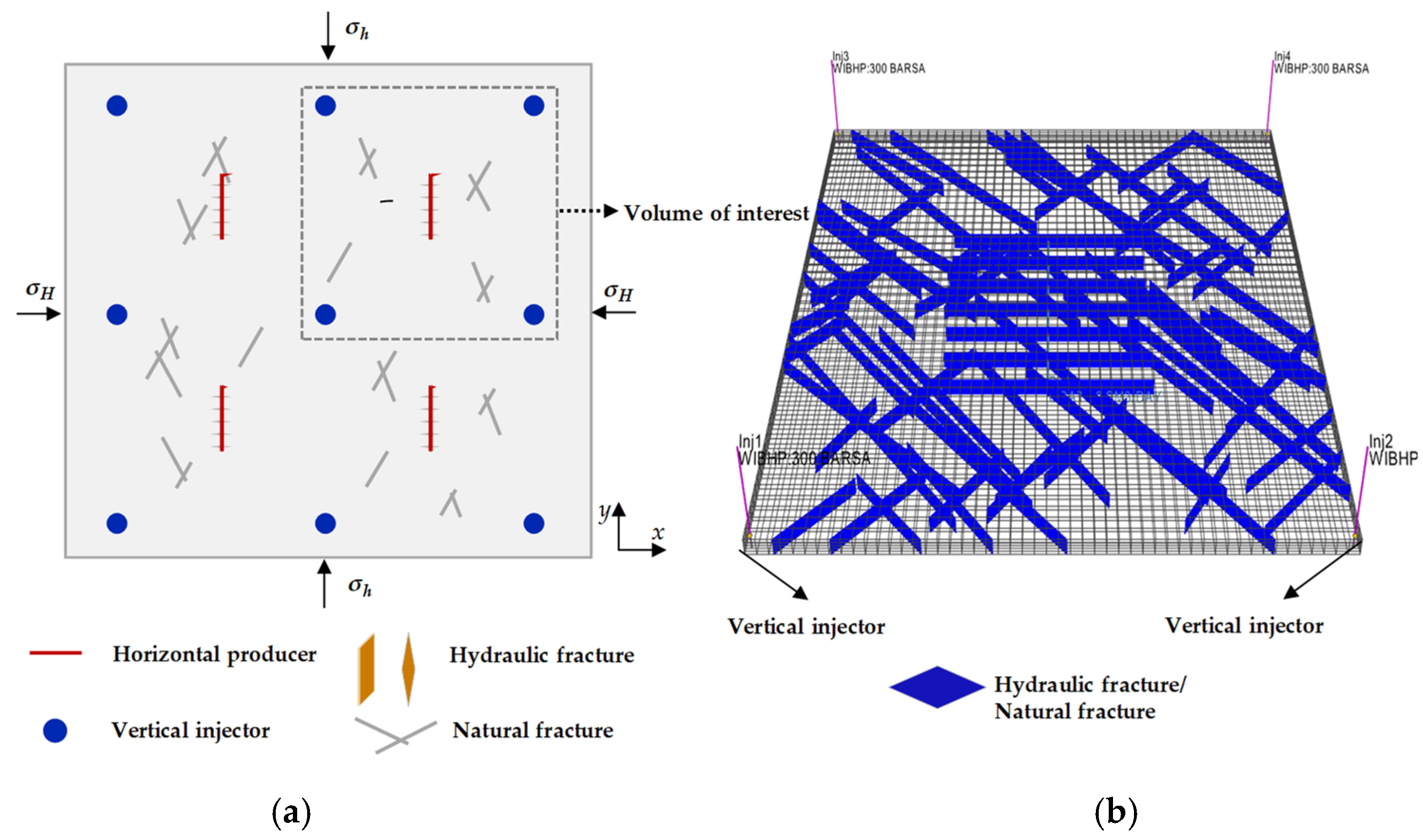
In this section, the main parameters adopted in the numerical simulation model were delineated and used for the subsequent simulations. The reservoir, fluid and well parameters were mainly derived from field data of the Baima Central Block, a tight sandstone reservoir in Changqing Oilfield. A five-spot well pattern was adopted for target reservoir development, and a schematic diagram of the well pattern is shown in Figure 2a.
Figure 2.
(a) Schematic diagrams illustrating the well pattern and the volume of interest, and (b) grid discretization results for the reservoir matrix in this work.
The fundamental parameters relevant to the target reservoir, such as reservoir properties, fluid properties, and well pattern, are summarized in Table 1. The four injection wells at the corners have the same parameter values, with a prescribed injection rate of 5 m3/d and a target well bottom-hole pressure of 30 MPa. The horizontal well is produced under the combined constraints, with a prescribed liquid production rate of 20 m3/d and a target well bottom-hole pressure of 10 MPa. The total simulation time for the numerical models in this work is 10 years.
Table 1.
Basic parameters used for numerical simulation.
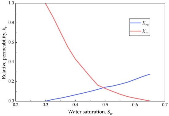
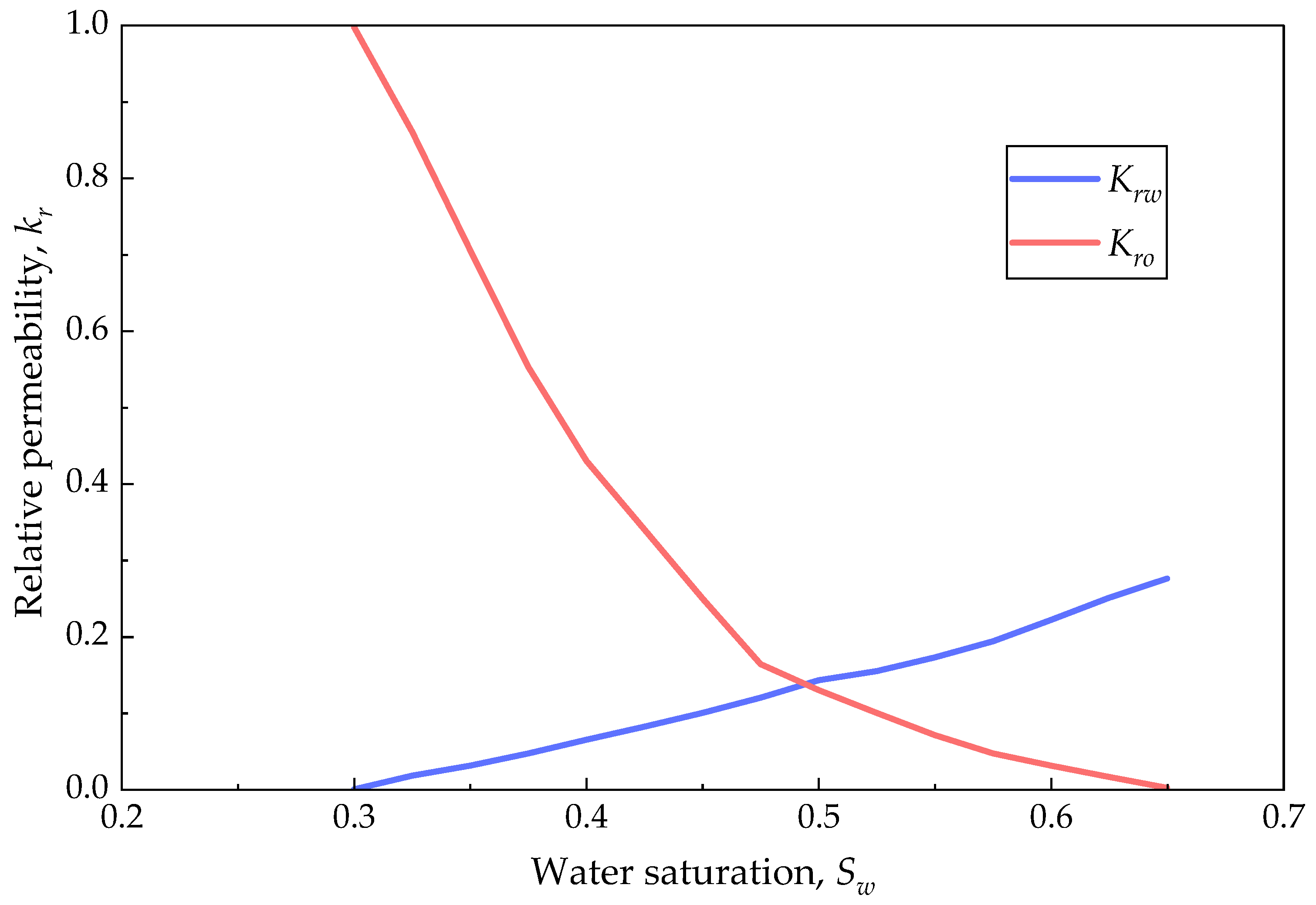
The relative permeability curves are shown in Figure 3. The original oil in place for the area of interest, which includes five wells, is 9.1 × 10⁴ t. The simulation cases in the following sections were conducted under the same reservoir and fluid conditions mentioned above.
Figure 3.
The relative permeability curves used for the numerical simulation.
The grid size adopted in this work is 8.1 m × 8.1 m × 2 m (shown in Figure 2b), resulting in 51 × 51 × 5 grids in the three directions. The total number of grid cells is 13,005. Moreover, the matrix grid discretization and the total number of matrix grids do not change as the hydraulic fracture or natural fracture networks change, which is one of the significant advantages of the EDFM approach adopted in this work.
3.2. Simulation Scenario Designs
The main concern of this work is to investigate the influence of well orientation and natural fractures on the well performance. Therefore, various well orientation angles were designed, including 15°, 30°, 45°, 60°, 75°, and 90°, with respect to the maximum horizontal stress direction.
The hydraulic fractures generated in this work were extended along the x-axis and had identical lengths and other properties. Accordingly, these hydraulic fractures display different spatial distributions while preserving the same fracture characteristics.
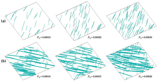
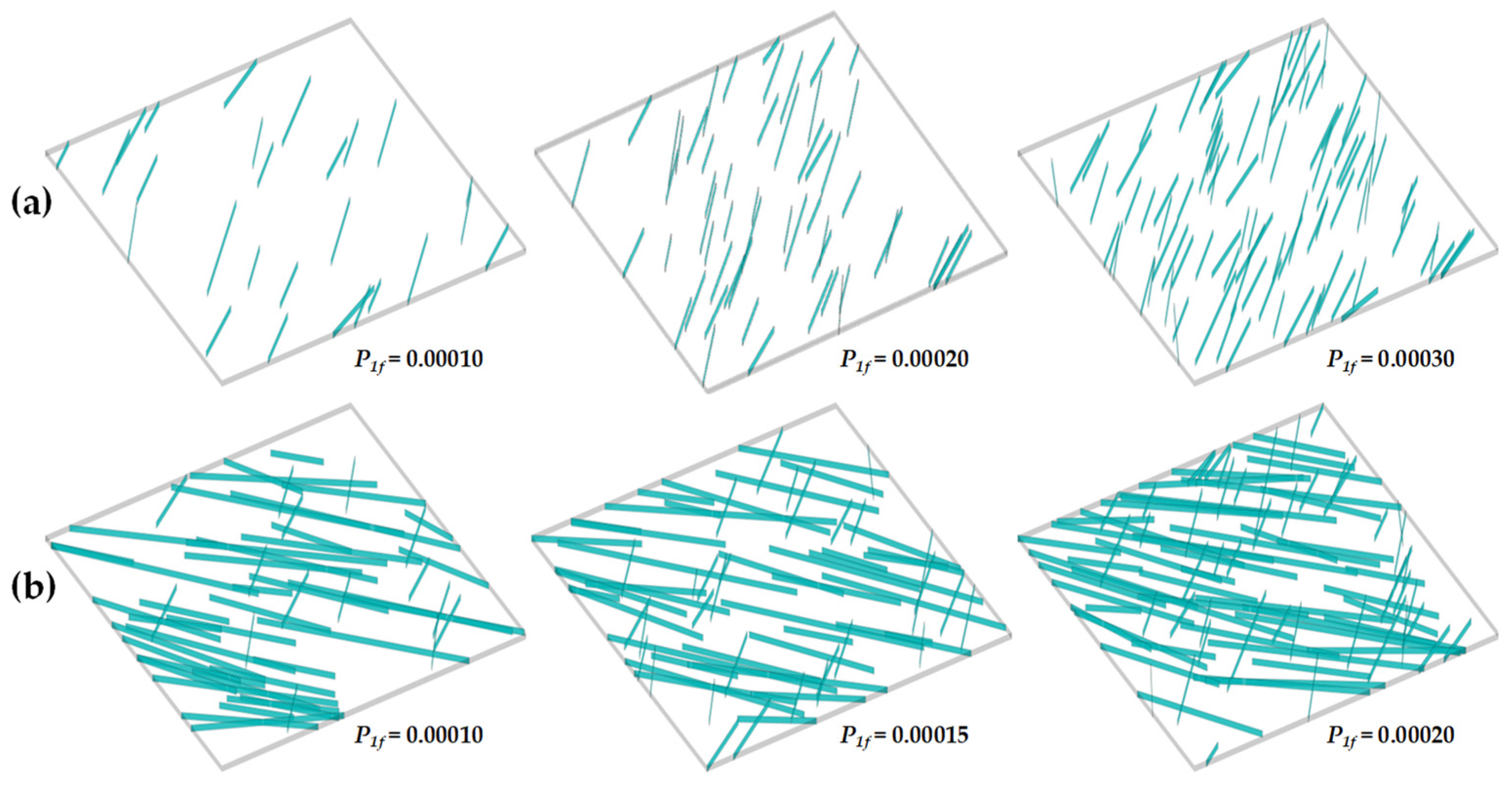
For natural fractures, three types were considered in the following sections: no NFs, single-set NFs, and conjugate NFs. Various fracture densities were investigated for the latter two types. The complete simulation scenarios are summarized in Table 2, and the generated NFs are displayed in Figure 4.
Table 2.
Simulation scenario designs with different well orientations and natural fractures.
Figure 4.
Generated NFs with different fracture densities for: (a) single-set NFs; (b) conjugate NFs.
A series of sensitivity analyses were subsequently conducted to evaluate well production performance, including cumulative oil production, water breakthrough time, pressure distribution behavior, and sweep efficiency under different scenarios.
4. Results and Discussion
In this section, sensitivity analyses were conducted to examine the optimal well orientation under various natural fracture scenarios. For reservoirs lacking NFs, the main focus was to determine the optimal well orientation and well pattern. Subsequently, the influence of natural fracture patterns and densities on optimal well orientation was thoroughly analyzed and discussed.
4.1. Optimization of Well Orientation Without Natural Fractures
4.1.1. Scenarios Without NFs
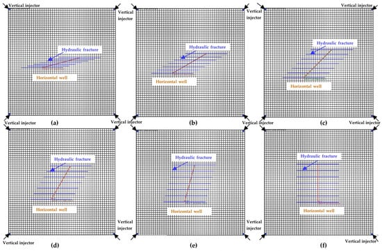
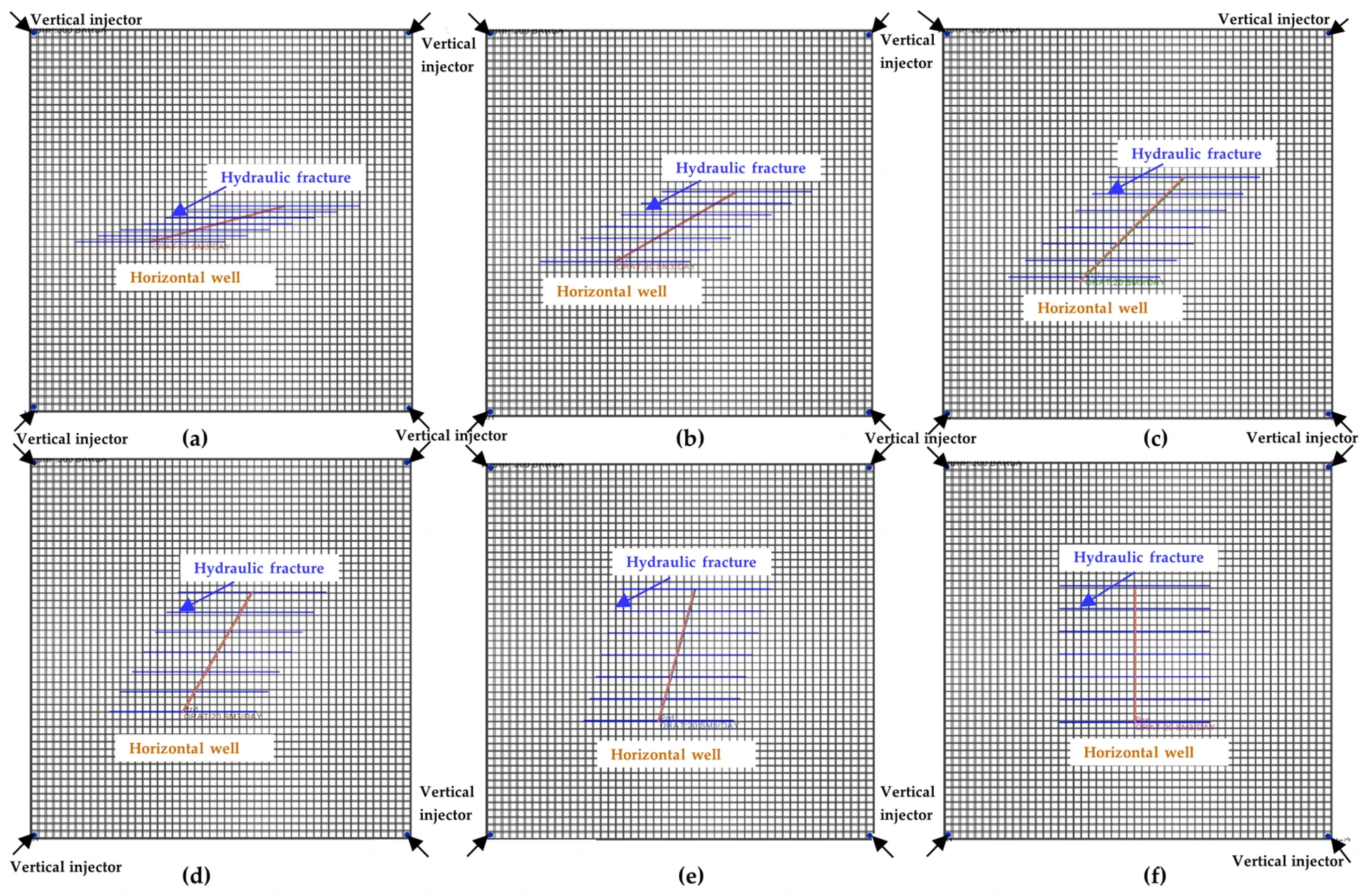
Numerical simulations were conducted for reservoirs without NFs, and a square well pattern was considered. Other parameters and settings for the numerical models were detailed in Section 3. Different well orientation angles were assigned in the numerical models, and the spatial distribution of the horizontal well and hydraulic fractures can be obtained accordingly, as illustrated in Figure 5.
Figure 5.
Spatial distribution of the horizontal well and hydraulic fractures for a square-shaped well pattern with different horizontal well orientation angles: (a) θ = 15°; (b) θ = 30°; (c) θ = 45°; (d) θ = 60°; (e) θ = 75°; (f) θ = 90°.
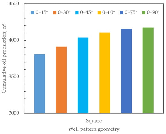
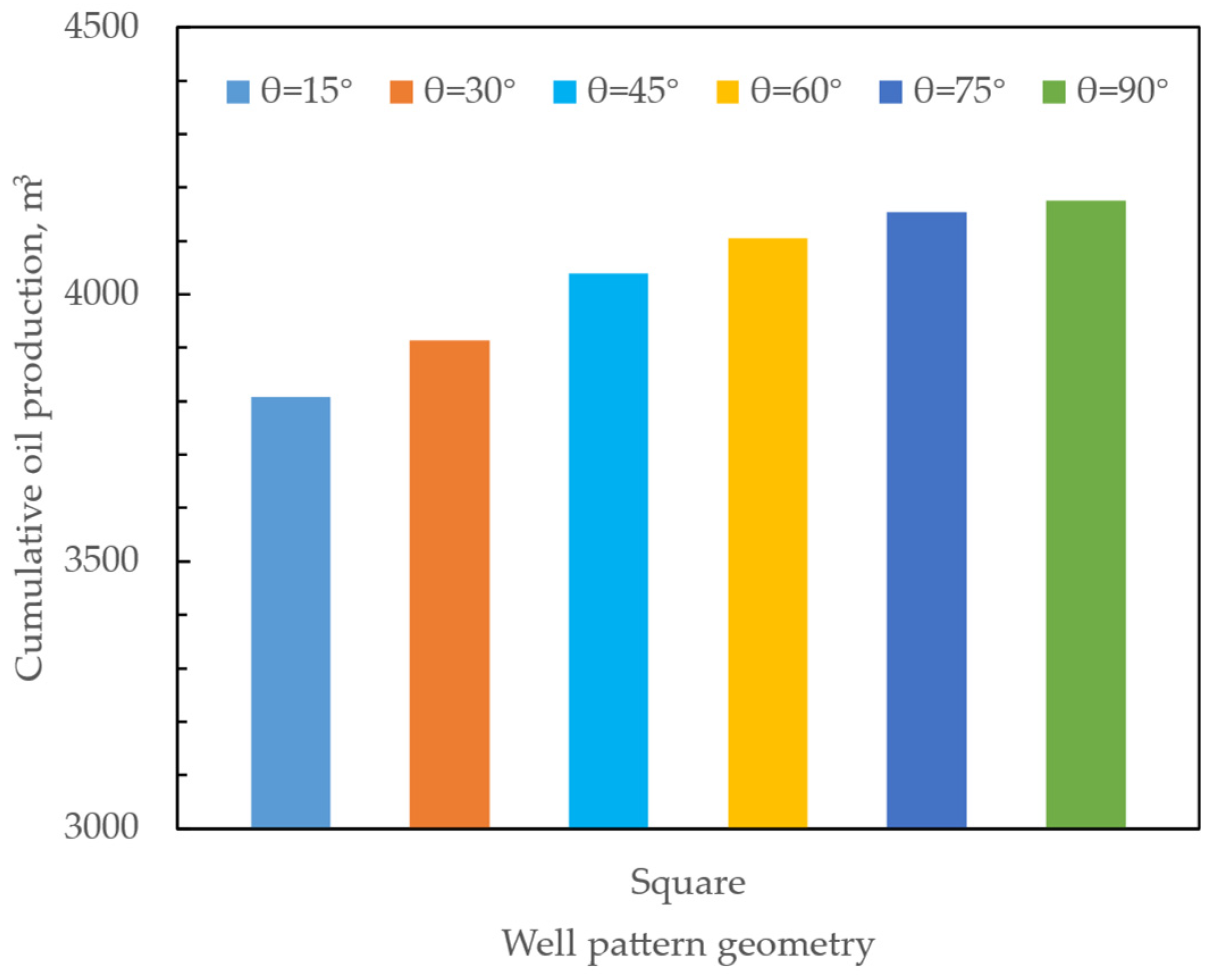
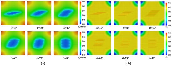
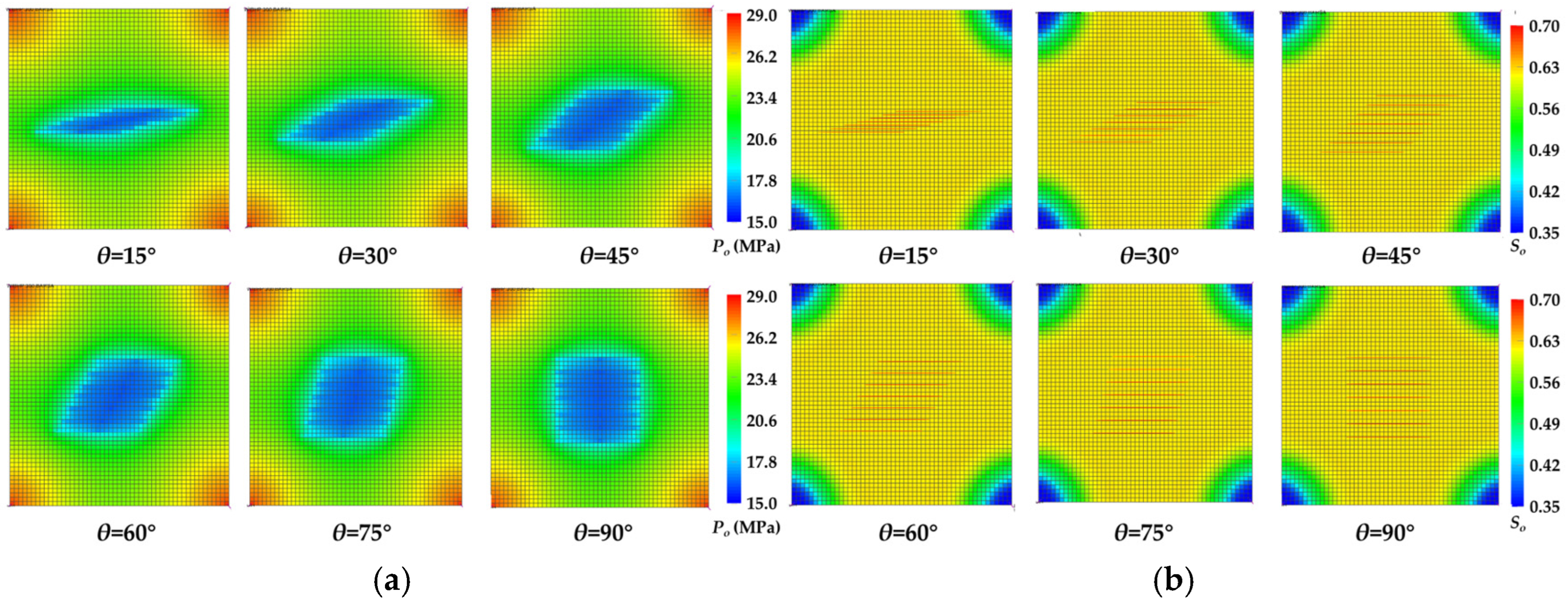
The cumulative oil production over the 10-year period was then derived from the numerical simulation results. As shown in Figure 6, the maximum oil production was observed when the wellbore trajectory was orientated perpendicular to the maximum horizontal stress direction (i.e., θ = 90°). This result is consistent with previous understanding [7], namely that the horizontal wellbore should be perpendicular to the generated hydraulic fractures to maximize the stimulated reservoir volume. As the orientation angle increases, cumulative oil production exhibits an upward trend, although the rate of increase gradually decreases. This phenomenon occurs mainly because the contact area between the hydraulic fractures and the reservoir matrix increases with increasing well orientation angle, despite the declining growth rate. Consequently, the enhancement in well production performance becomes less pronounced. Figure 7a,b depict the pressure and oil saturation distribution after 5 years of production for the scenarios with different well orientation angles. As shown in Figure 7a, the pressure-wave influence area reaches its maximum when θ = 90° (the low-pressure region shown in blue).
Figure 6.
Effect of well orientation angle on well production performance under a square well pattern.
Figure 7.
Distribution of pressure and oil saturation after 5 years of production for the scenarios under various well orientation angles: (a) pressure distribution; (b) oil saturation.
4.1.2. Effect of Well Pattern Geometry on Optimal Well Orientation
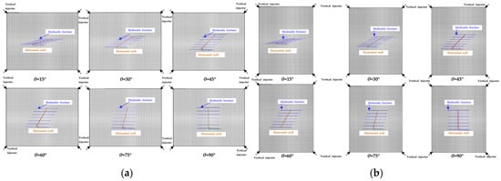
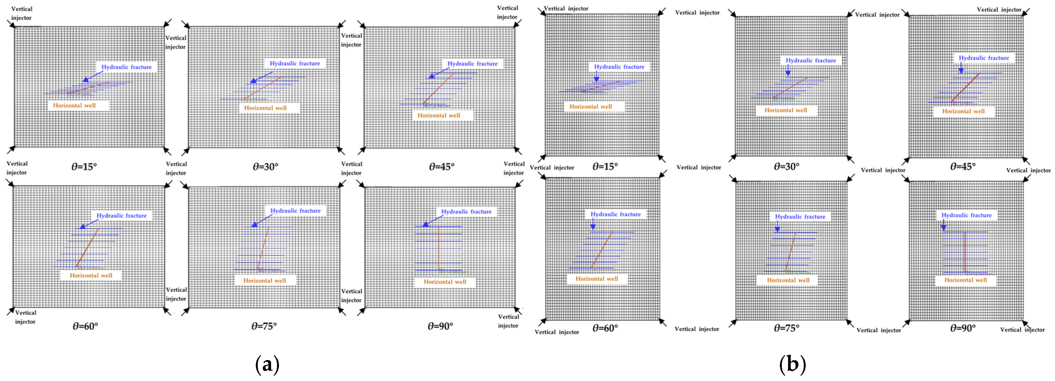
Additionally, the effects of well pattern geometry on well production performance and the optimal well orientation angle were investigated. Two additional well pattern geometries, namely x-rectangular and y-rectangular patterns, were adopted in this work. Figure 8a,b depict the well pattern geometry together with the generated hydraulic fractures under various well orientation angles. For the X-rectangular well pattern, the longer dimension of the rectangular well pattern is along the x-direction, while for the Y-rectangular well pattern, the longer dimension is along the y-direction.
Figure 8.
Spatial distribution of the horizontal well and hydraulic fractures in a rectangular reservoir with different horizontal well orientation angles: (a) x-rectangular well pattern; (b) y-rectangular well pattern.
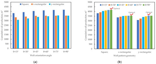
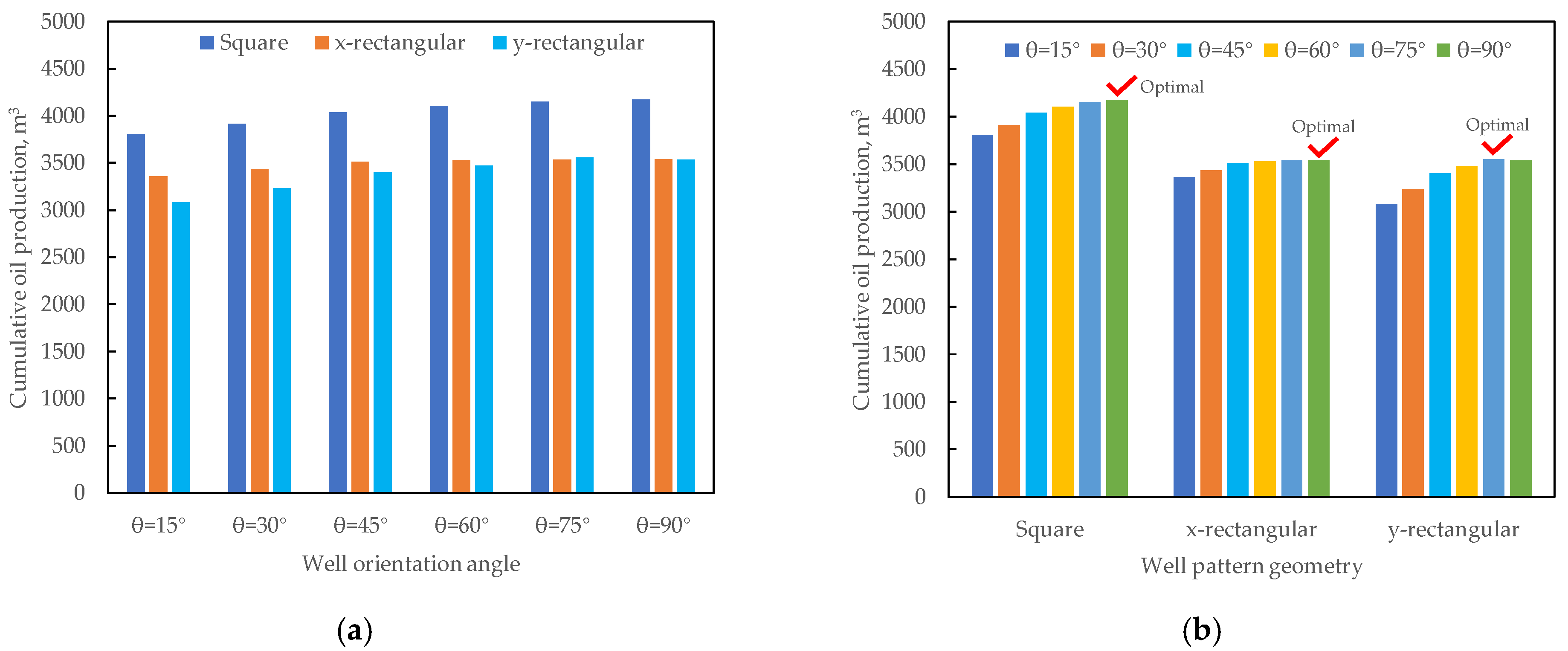
Cumulative oil production under three well pattern geometries and various well orientation angles is shown in Figure 9a,b. It can be found that the rectangular well pattern geometry results in lower oil production, particularly for the y-rectangular type. This occurs because the rectangular reservoir leads to uneven water sweep efficiency from the injection well to the fractured production well, which is especially pronounced for the y-rectangular well pattern. Because hydraulic fractures extend along the x-axis, they can enhance the fluid flow in the x-axis direction through high-permeability fractures. Consequently, for the y-rectangular well pattern, cumulative oil production is the lowest among the three well pattern geometries under the same well orientation angle. In contrast, the square well pattern is recommended for the development of reservoirs lacking natural fractures.
Figure 9.
(a) Effect of well pattern geometry on cumulative oil production under various well orientation angles; (b) effect of well orientation angles on well production performance under different well pattern geometries.
Meanwhile, comparison of the optimal well orientation angle under different well pattern geometries shows that the horizontal wellbore trajectory should align with the minimum horizontal stress direction (i.e., θ = 90°). Adjusting the well orientation can change the distance between the injection well and the fractured production well. Particularly, as the well orientation angle decreases, the shorter distance between the injector and the hydraulic fractures tends to advance the water breakthrough time of the production well. The current results show that for reservoirs lacking NFs, there is no need to adjust the well orientation angle. Such adjustment not only provides no significant benefits but also negatively affects the final cumulative oil production.
4.2. Optimization of Well Orientation with One Set of Natural Fractures
4.2.1. Effect of Fracture Density of Single-Set NFs on Well Performance
In this part, single-set NFs were considered in the numerical simulation model, and the natural fracture parameters and corresponding natural fracture morphologies were detailed in Table 2 and Figure 4, respectively. Similarly, cumulative oil production at the end of the 10-year period was summarized.
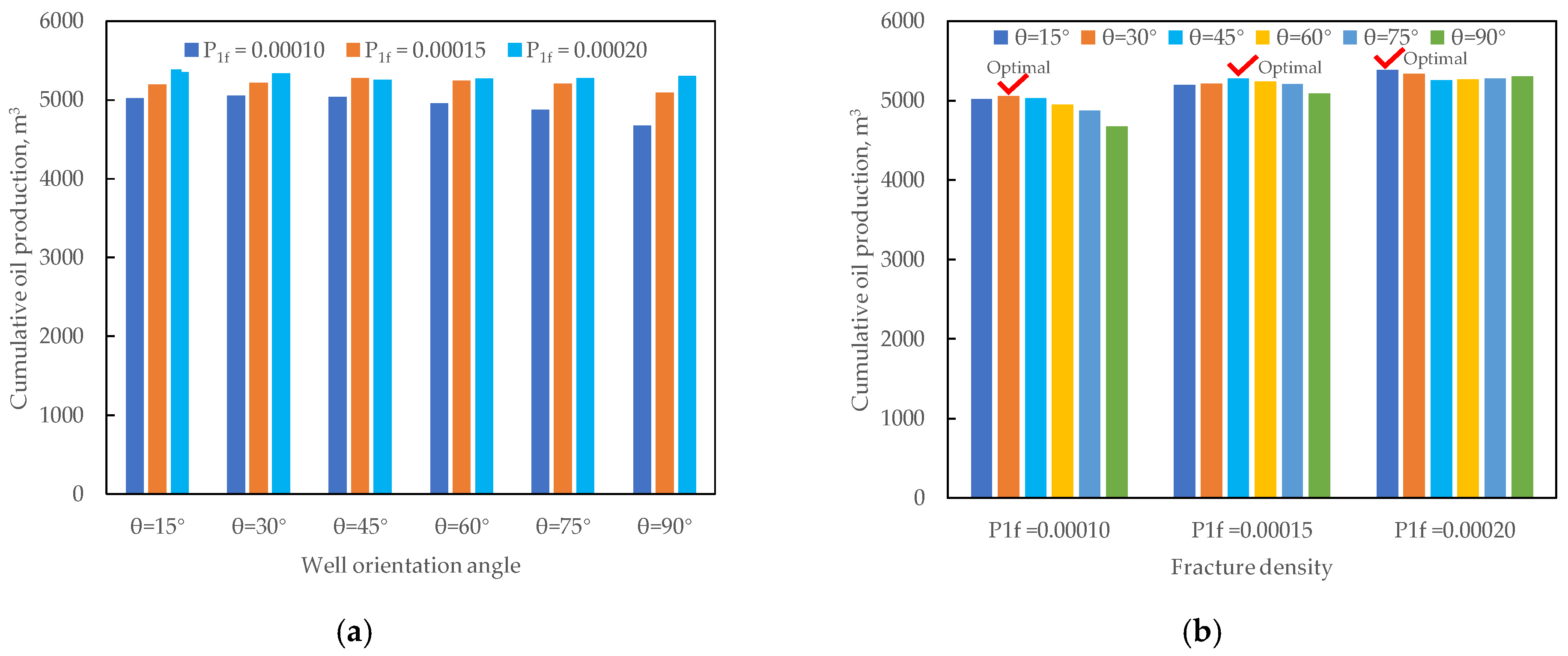
As shown in Figure 10a, cumulative oil production increases with natural fracture density. In general, natural fracture density can influence well production performance in two opposite ways. From a positive perspective, natural fractures can improve the fluid flow capacity and even act as the main flow channels in tight formations. As NF density increases, fracture network connectivity is enhanced. Meanwhile, the swept area of the injected water increases at the same time, which can efficiently support reservoir pressure and enhance the utilization degree of the oil in place and the long-term productivity of the reservoir. Conversely, when NFs are overly developed or when fractures extend mainly along the direction between the injector and the producer, the injected water preferentially flows through high-permeability NFs, resulting in early water breakthrough in production wells. Under these conditions, NFs may have an unfavorable influence on oil production or even adversely decrease oil production. In this work, the reservoir with a permeability of nearly 0.1 mD demonstrates that the production-enhancing effect of NFs is dominant, and higher NF density leads to better well production performance and higher cumulative oil production.
Figure 10.
(a) Effect of single-set NF density on well production performance; (b) effect of well orientation angle on well production performance under various single-set NF densities.
4.2.2. Optimal Well Orientation Under Single-Set NF Conditions
As shown in Figure 10b, with increasing natural fracture density, the optimal well orientation angle in this work shows an obvious transition pattern. When NF density is low to medium (i.e., P1f < = 0.0002), the optimal well orientation angle is 90°, which is the same as that in a reservoir without NFs. However, as NF density continues to increase, the optimal well orientation angle is approximately 15°, whereas a 90° azimuth no longer provides an advantage in cumulative oil production.
This phenomenon demonstrates that NFs have an important impact on the orientation optimization of horizontal wells. The mean fracture azimuth is 45° in this work. Therefore, when the NF density is low, the seepage capacity of the reservoir is still governed by the matrix system, whereas NFs only improve oil production by increasing reservoir seepage capacity. Thus, the horizontal wellbore trajectory should be deployed perpendicular to the direction of maximum horizontal stress, which increases the contact area between the matrix and the hydraulic fracture systems and consequently maximizes cumulative oil production.
However, as NF density continues to increase (i.e., 0.0003 in this work), the fracture network can form strong connectivity, and the reservoir seepage capacity is gradually controlled by the fracture system. Under such conditions, if the well is still deployed at a 90° orientation angle, high-conductivity flow channels can easily form along the direction between wells. Injected water can then flow readily from the dominant fracture system to the horizontal wellbore, resulting in early water breakthrough and low sweep efficiency. In contrast, if the orientation angle is small (i.e., θ = 15°), a longer distance between the injector and the horizontal producer can be obtained, resulting in later water breakthrough and higher cumulative oil production.
Overall, increasing NF density can result in a gradual transition from the matrix-dominated flow to fracture-dominated flow. The optimal horizontal well orientation shifts from a direction perpendicular to the fractures (90°) to a direction nearly parallel to the fractures (15°) as the natural fracture density increases.
4.3. Optimization of Well Orientation Under Conjugate Natural Fractures
4.3.1. Effect of Fracture Density of Conjugate NFs on Well Performance
In reservoirs containing conjugate NFs, two sets of shear fractures that cross each other exist in the formation. These conjugate fractures typically form because of shear failure induced by the same tectonic stress field. Figure 4b illustrates the conjugate NFs with varying densities adopted in this work.
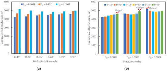
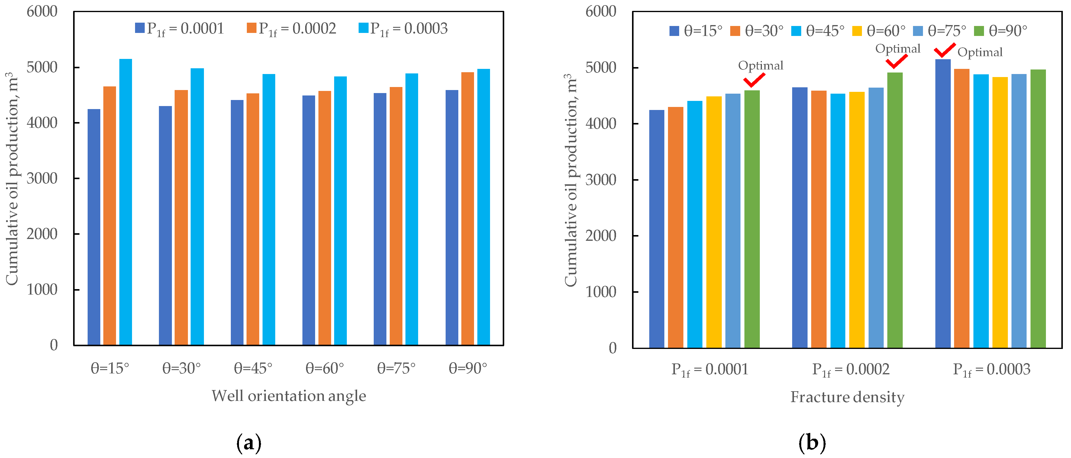
The influence of conjugate NF density on well production performance can be seen in Figure 11a. Similar findings indicate that higher NF density can generate better well production performance. The reason for this phenomenon is consistent with that for reservoirs with single-set NFs. For reservoirs with conjugate NFs, the positive role of NFs dominates. Specifically, natural fractures can enhance the seepage capacity of tight formations and increase the swept area during water flooding. This positive effect can increase the cumulative production and improve the overall development performance of the fractured reservoirs.
Figure 11.
(a) Effect of conjugate NF density on well production performance; (b) effect of well orientation angle on well production performance under various conjugate NF densities.
4.3.2. Optimal Well Orientation Under Conjugate NF Conditions
Conjugate NFs are more complicated than single-set NFs and result in improved fracture connectivity. The optimal well orientation angle was determined under different conjugate NF densities. As shown in Figure 11b, the optimal well orientation angle for reservoirs with complex conjugate NFs is small (15–45° in this work). This is because a larger orientation angle can result in stronger connectivity between the fractured horizontal well and the injection well. Injected fluid then flows rapidly along the high-permeability fractures, causing early water breakthrough and a low oil production rate. When the orientation angle is smaller, a smaller hydraulic fracture region is obtained, which can reduce the connectivity between natural fractures and hydraulic fractures. Therefore, the water channeling effect is less severe, and a better sweep efficiency and higher oil production can be obtained.
When the NF density is 0.00010, the optimal well orientation angle is 30°. Because fractures are sparse at this density, a moderate offset can increase the contact area between the hydraulic fractures and the reservoir, thereby improving the connectivity and flow capacity. When the NF density increases to 0.00015, a larger well orientation angle of 45° is beneficial because the hydraulic fractures can intersect more natural fractures and achieve the best production performance. As NF fracture increases to 0.0002, the optimal orientation angle decreases to 15°. For reservoirs with high-density conjugate NFs, highly connected fractures can cause water channeling and early water breakthrough. Thus, a smaller orientation angle can keep the hydraulic fractures farther from the connected NFs and can reduce unnecessary water channeling.
5. Conclusions
- (1)
- The existence of NFs in tight formations has a significant impact on the optimal horizontal well orientation, and an obvious difference in well orientation angle can be observed under different natural fracture patterns and densities.
- (2)
- For reservoirs without NFs and those with low- to medium-density single-set NFs, the optimal horizontal well orientation is perpendicular to the maximum horizontal stress direction.
- (3)
- For reservoirs with high-density single-set NFs, an appropriate rotation of the horizontal wellbore trajectory is favorable for cumulative oil production. The optimal orientation angle is approximately 15° for the reservoir with high-density single-set NFs in this work.
- (4)
- For reservoirs with conjugate fractures, the advantages of well orientation are more obvious, and the optimal well orientation angle is highly dependent on NFs. This indicates that well trajectory optimization is more prominent under complex NF conditions.
- (5)
- The design and optimization of horizontal well trajectory should be based on NF characterization. Further study should focus on the stress shadow effect caused by the reduction of cluster spacing after well orientation. Additionally, it is essential to examine time-varying hydraulic fracture properties on the optimization of well orientations.
- (6)
- Future work should incorporate geomechanical coupling to investigate the influence of stress magnitude and direction on hydraulic fracture propagation and production performance.
Author Contributions
Conceptualization, J.S. and L.J.; methodology, J.W. and X.L.; software, Y.F. and Q.L.; validation, Y.F. and Q.L.; formal analysis, X.W. and J.L.; writing—original draft preparation, J.S. and L.J.; writing—review and editing, J.L. and L.J.; funding acquisition, J.S. All authors have read and agreed to the published version of the manuscript.
Funding
This research was funded by Oil & Gas Major Project (No. 2025ZD1405400).
Data Availability Statement
The original contributions presented in this study are included in the article material. Further inquiries can be directed to the corresponding author.
Conflicts of Interest
Authors Jianchao Shi, Jiwei Wang, Xiaoke Li, Yongjian Feng and Qiang Liu were employed by the Exploration and Development Research Institute, PetroChina Changqing Oilfield Company. The remaining authors declare that the research was conducted in the absence of any commercial or financial relationships that could be construed as a potential conflict of interest.
Abbreviations
The following abbreviations are used in this manuscript:
| EDFM | Embedded discrete fracture model |
| NFs | Natural fractures |
| NNCs | Non-neighboring connections |
| θ | Well orientation angle |
| T | Transmissibility factor |
| P1f | Fracture density |
| L | Horizontal wellbore length |
| N | Fracture number |
| xf | Fracture half-length |
References
- Wang, L.; Yu, W. Mechanistic Simulation Study of Gas Puff and Huff Process for Bakken Tight Oil Fractured Reservoir. Fuel 2019, 239, 1179–1193. [Google Scholar] [CrossRef] [Scilit]
- Clarkson, C.R. Production Data Analysis of Unconventional Gas Wells: Review of Theory and Best Practices. Int. J. Coal Geol. 2013, 109, 101–146. [Google Scholar] [CrossRef] [Scilit]
- Zhou, W.; Banerjee, R.; Poe, B.D.; Spath, J.; Thambynayagam, M. Semianalytical Production Simulation of Complex Hydraulic-Fracture Networks. SPE J. 2014, 19, 6–18. [Google Scholar]
- Hofmann, H.; Babadagli, T.; Zimmermann, G. Numerical Simulation of Complex Fracture Network Development by Hydraulic Fracturing in Naturally Fractured Ultratight Formations. J. Energy Resour. Technol. 2014, 136, 042905. [Google Scholar] [CrossRef] [Scilit]
- Soliman, M.Y.; Hunt, J.L.; El Rabaa, A.M. Fracturing Aspects of Horizontal Wells. J. Pet. Technol. 1990, 42, 966–973. [Google Scholar] [CrossRef] [Scilit]
- Fisher, M.K.; Wright, C.A.; Davidson, B.M.; Steinsberger, N.P.; Buckler, W.S.; Goodwin, A.; Fielder, E.O. Integrating Fracture Mapping Technologies To Improve Stimulations in the Barnett Shale. SPE Prod. Facil. 2005, 20, 85–93. [Google Scholar] [CrossRef] [Scilit]
- Rostami, E.; Boness, N.; Zoback, M.D. Significance of Well Orientation on Cumulative Production From Wells in the Bakken Region. In Proceedings of the 8th Unconventional Resources Technology Conference, Online, 20–22 July 2020; American Association of Petroleum Geologists: Tulsa, OK, USA, 2020. [Google Scholar] [CrossRef] [Scilit]
- Kazemi, H. Pressure Transient Analysis of Naturally Fractured Reservoirs with Uniform Fracture Distribution. Soc. Pet. Eng. J. 1969, 9, 451–462. [Google Scholar] [CrossRef] [Scilit]
- Warren, J.E.; Root, P.J. The Behavior of Naturally Fractured Reservoirs. Soc. Pet. Eng. J. 1963, 3, 245–255. [Google Scholar] [CrossRef] [Scilit]
- Karimi-Fard, M.; Durlofsky, L.J.; Aziz, K. An Efficient Discrete-Fracture Model Applicable for General-Purpose Reservoir Simulators. SPE J. 2004, 9, 227–236. [Google Scholar] [CrossRef] [Scilit]
- Berre, I.; Doster, F.; Keilegavlen, E. Flow in Fractured Porous Media: A Review of Conceptual Models and Discretization Approaches. Transp. Porous Med. 2019, 130, 215–236. [Google Scholar] [CrossRef] [Scilit]
- Hyman, J.D.; Gable, C.W.; Painter, S.L.; Makedonska, N. Conforming Delaunay Triangulation of Stochastically Generated Three Dimensional Discrete Fracture Networks: A Feature Rejection Algorithm for Meshing Strategy. SIAM J. Sci. Comput. 2014, 36, A1871–A1894. [Google Scholar] [CrossRef] [Scilit]
- Moinfar, A.; Varavei, A.; Sepehrnoori, K.; Johns, R.T. Development of an Efficient Embedded Discrete Fracture Model for 3D Compositional Reservoir Simulation in Fractured Reservoirs. SPE J. 2014, 19, 289–303. [Google Scholar] [CrossRef] [Scilit]
- Li, L.; Lee, S.H. Efficient Field-Scale Simulation of Black Oil in a Naturally Fractured Reservoir Through Discrete Fracture Networks and Homogenized Media. SPE Reserv. Eval. Eng. 2008, 11, 750–758. [Google Scholar] [CrossRef] [Scilit]
- Liu, J.; Jiang, L.; Liu, T.; Yang, D. Modeling Tracer Flowback Behaviour for a Multifractured Horizontal Well in a Tight Oil Reservoir using the Embedded Discrete Fracture Model. J. Pet. Sci. Eng. 2022, 212, 110347. [Google Scholar] [CrossRef] [Scilit]
- Liu, J.; Jiang, L.; Liu, T.; Yang, D. Characterization of Fractal-like Fracture Network Using Tracer Flowback Tests for a Multifractured Horizontal Well in a Tight Formation. Fractals 2022, 30, 2250133. [Google Scholar] [CrossRef] [Scilit]
- Poli, R.E.B.; Barbosa Machado, M.V.; Sepehrnoori, K. Advancements and Perspectives in Embedded Discrete Fracture Models (EDFM). Energies 2024, 17, 3550. [Google Scholar] [CrossRef] [Scilit]
- AlTwaijri, M.; Xia, Z.; Yu, W.; Qu, L.; Hu, Y.; Xu, Y.; Sepehrnoori, K. Numerical Study of Complex Fracture Geometry Effect on Two-Phase Performance of Shale-Gas Wells Using the Fast EDFM Method. J. Pet. Sci. Eng. 2018, 164, 603–622. [Google Scholar] [CrossRef] [Scilit]
- Wu, Z.; Cui, C.; Jia, P.; Wang, Z.; Sui, Y. Advances and Challenges in Hydraulic Fracturing of Tight Reservoirs: A Critical Review. Energy Geosci. 2022, 3, 427–435. [Google Scholar] [CrossRef] [Scilit]
- Li, J.; Zhou, X.; Liu, X.; Gayubov, A.; Shamil, S. Cross-Scale Seepage Characteristics of Fractured Horizontal Wells in Tight Gas Reservoirs. ACS Omega 2023, 8, 24291–24301. [Google Scholar] [CrossRef] [Scilit] [PubMed]
- Hubbert, M.K.; Willis, D.G. Mechanics of Hydraulic Fracturing. Trans. AIME 1957, 210, 153–168. [Google Scholar] [CrossRef] [Scilit]
- Lakirouhani, A.; Jolfaei, S. Assessment of Hydraulic Fracture Initiation Pressure Using Fracture Mechanics Criterion and Coupled Criterion with Emphasis on the Size Effect. Arab. J. Sci. Eng. 2024, 49, 5897–5908. [Google Scholar] [CrossRef] [Scilit]
- Crosby, D.G.; Rahman, M.M.; Rahman, M.K.; Rahman, S.S. Single and Multiple Transverse Fracture Initiation from Horizontal Wells. J. Pet. Sci. Eng. 2002, 35, 191–204. [Google Scholar] [CrossRef] [Scilit]
- Burghardt, J.; Knox, H.; Strickland, C.; Vermeul, V.; Fu, P.; Ulrich, C.; McClure, M.; Ingraham, M.; Schwering, P.; Kneafsey, T.; et al. Transverse Hydraulic Fracture Initiation: Insights from Intermediate-Scale Hydraulic Fracture Tests. arXiv 2021. [Google Scholar] [CrossRef] [Scilit]
- Sherratt, J.; Sharifi Haddad, A.; Wejzerowski, F.; Rafati, R. Optimising Well Orientation in Hydraulic Fracturing of Naturally Fractured Shale Gas Formations. J. Nat. Gas Sci. Eng. 2021, 94, 104141. [Google Scholar] [CrossRef] [Scilit]
- Xu, S.; Guo, J.; Feng, Q.; Ren, G.; Li, Y.; Wang, S. Optimization of Hydraulic Fracturing Treatment Parameters to Maximize Economic Benefit in Tight Oil. Fuel 2022, 329, 125329. [Google Scholar] [CrossRef] [Scilit]
- Will, R.; Archer, R.; Dershowitz, B. Integration of Seismic Anisotropy and Reservoir-Performance Data for Characterization of Naturally Fractured Reservoirs Using Discrete-Feature-Network Models. SPE Reserv. Eval. Eng. 2005, 8, 132–142. [Google Scholar] [CrossRef] [Scilit]
- Bagherinezhad, A.; Boozarjomehry Bozorgmehry, R.; Pishvaie, M.R. Multi-Criterion Based Well Placement and Control in the Water-Flooding of Naturally Fractured Reservoir. J. Pet. Sci. Eng. 2017, 149, 675–685. [Google Scholar] [CrossRef] [Scilit]
- Xu, J.; Guo, W.; Zhou, W. Well Placement Optimization for Fractured Reservoirs: Coupling StoSAG and EDFM. Geofluids 2022, 2022, 5912732. [Google Scholar] [CrossRef] [Scilit]
- Li, H.; Duan, H.; Qin, Q.; Zhao, T.; Fan, C.; Luo, J. Characteristics and Distribution of Tectonic Fracture Networks in Low Permeability Conglomerate Reservoirs. Sci. Rep. 2025, 15, 5914. [Google Scholar] [CrossRef] [Scilit] [PubMed]
- Peacock, D.C.P.; Nixon, C.W.; Rotevatn, A.; Sanderson, D.J.; Zuluaga, L.F. Glossary of Fault and Other Fracture Networks. J. Struct. Geol. 2016, 92, 12–29. [Google Scholar] [CrossRef] [Scilit]
- Sanderson, D.J.; Nixon, C.W. The Use of Topology in Fracture Network Characterization. J. Struct. Geol. 2015, 72, 55–66. [Google Scholar] [CrossRef] [Scilit]
- Lorenz, J.C.; Sterling, J.L.; Schechter, D.S.; Whigham, C.L.; Jensen, J.L. Natural Fractures in the Spraberry Formation, Midland Basin, Texas: The Effects of Mechanical Stratigraphy on Fracture Variability and Reservoir Behavior. AAPG Bull. 2002, 86, 505–524. [Google Scholar] [CrossRef] [Scilit]

Disclaimer/Publisher’s Note: The statements, opinions and data contained in all publications are solely those of the individual author(s) and contributor(s) and not of MDPI and/or the editor(s). MDPI and/or the editor(s) disclaim responsibility for any injury to people or property resulting from any ideas, methods, instructions or products referred to in the content. |
© 2026 by the authors. Licensee MDPI, Basel, Switzerland. This article is an open access article distributed under the terms and conditions of the Creative Commons Attribution (CC BY) license.