


Abstract
With the continuous reduction in equivalent inertia in modern power systems, thermal power units are required to provide faster and more sensitive primary frequency regulation. Under this background, small frequency deviation amplification (compensation) has been widely implemented in governing systems. However, while such high-gain control improves frequency response performance, it may significantly deteriorate system damping and even induce low-frequency oscillations (LFO). The underlying mechanism, however, has not been fully clarified from a theoretical perspective. To address this issue, a refined electromechanical coupled model of a thermal power unit governing system incorporating small frequency deviation amplification is established, and the corresponding linearized model is derived. Based on the damping torque analysis method, the influence of amplification gain on mechanical damping is rigorously analyzed in the frequency domain, and the fundamental mechanism leading to damping degradation is revealed. Furthermore, time-domain simulations are conducted to compare system dynamic responses under different compensation parameter settings. The results indicate that the amplification gain has a significant impact on LFO characteristics. Improper parameter settings can directly reduce system damping and trigger oscillations.
1. Introduction
With the rapid advancement of the global energy transition, the penetration of renewable energy sources such as wind and solar power has been continuously increasing in modern power systems [1]. The emerging power system is characterized by a high penetration of renewable energy and extensive integration of power electronic devices, significantly reducing the equivalent inertia of the system and weakening the inherent ability to resist disturbances. Specifically, traditional synchronous generators provide inherent rotational inertia and natural mechanical damping through their massive rotors and amortisseur windings. As converter-interfaced generation displaces these synchronous machines, the equivalent system inertia is drastically reduced because standard grid-following inverters lack physical rotating mass and electromagnetically decouple the generation source from the grid frequency. Within the established electromechanical model, diminished inertia dictates a steeper rate of change in frequency and larger transient frequency deviations during disturbances. Simultaneously, this decoupling effect diminishes the natural load damping. As a result, the frequency dynamics become more complex and uncertain, leading to new stability challenges, among which low-frequency oscillations (LFOs) have attracted considerable attention [2,3].
LFOs typically occur in the frequency range of 0.1–2.5 Hz and are essentially electromechanical oscillations among generators coupled through the transmission network. When the system lacks sufficient damping or is subjected to sustained disturbances, such oscillations can continuously increase, posing serious threats to the secure operation of large-scale interconnected power systems and potentially leading to cascading failures or even widespread blackouts [4]. Therefore, investigating the mechanisms and factors that influence LFOs is of great importance to ensure the stability of the system.
Thermal power units remain the primary providers of frequency regulation in current power systems, and their governing system dynamics play a role in frequency stability [5]. To meet increasingly stringent primary frequency regulation requirements, especially under small frequency deviation conditions, small frequency deviation amplification strategies have been widely implemented in practice. By increasing the effective control gain within a narrow frequency deviation range, this approach significantly improves the response speed and sensitivity of generating units [6].
From a control perspective, small frequency deviation amplification can be regarded as a variable-gain control strategy. While it enhances frequency regulation performance, the increased gain inevitably alters the dynamic characteristics of the governing system, particularly in the low-frequency range. It has been recognized that both governing systems and excitation systems jointly determine the damping characteristics of electromechanical oscillations [7]. When the effective gain of the governing system is significantly increased at low frequencies, the phase relationship between mechanical power and speed deviation may be altered, leading to a reduction in damping torque or even the introduction of negative damping, thereby aggravating LFOs.
Despite these concerns, most existing studies on LFOs are based on simplified linear models, where the governing system is typically represented by fixed droop characteristics [8,9,10]. Such models fail to capture the variable-gain behavior introduced by small frequency deviation amplification. In practical applications, to achieve a balance between fast response under small disturbances and stable behavior under large disturbances, the compensation strategy is often implemented as a piecewise function, resulting in a nonlinear and variable-structure system. Consequently, conventional modeling approaches are insufficient to accurately characterize its impact on system damping [11].
Despite the extensive research on low-frequency oscillations and variable-gain frequency regulation, most existing studies rely on simplified linear models with fixed or piecewise droop characteristics, which do not account for the dynamic effects introduced by small frequency deviation amplification [12,13]. Although damping torque analysis has been widely used to assess electromechanical damping, previous works rarely provide a systematic frequency-domain analysis that links variable-gain control to reductions in mechanical damping. In contrast, this study develops a refined electromechanical coupled model that incorporates small frequency deviation amplification and uses damping torque analysis to rigorously quantify its effect on mechanical damping. The results reveal the fundamental mechanism by which increased amplification gain can degrade system damping and induce low-frequency oscillations, providing both theoretical insight and guidance for parameter tuning in thermal power unit governing systems. To our knowledge, this is the first study to offer such a unified analytical perspective on the interaction between small frequency deviation amplification and LFO dynamics [12,13].
To address these issues, it is necessary to develop a refined electromechanical coupled model that incorporates the dynamic characteristics of small frequency deviation amplification and to theoretically investigate its impact on LFO damping.
In this paper, the low-frequency oscillation characteristics of thermal power unit governing systems with small frequency deviation amplification are investigated. The main contributions are summarized as follows. First, a generator–grid coupled model incorporating small frequency deviation amplification is established, and the corresponding linearized state-space representation is derived. Second, the influence mechanism of amplification gain on electromechanical oscillation damping is systematically analyzed based on damping torque analysis in the frequency domain. Finally, time-domain simulations are conducted to validate the theoretical results and to examine the impact of parameter settings on system dynamic performance. The findings of this work provide theoretical support for parameter optimization and stability enhancement in modern power systems.
2. Modeling of Governing System with Small Frequency Deviation Amplification
To quantitatively evaluate the impact of small frequency deviation amplification on low-frequency oscillations, a generator–grid coupled dynamic model is established. Specifically, the overall model consists of the turbine-generator rotor dynamics, speed governing system, electro-hydraulic servo mechanism, steam turbine model, small frequency deviation amplification module, and the external power grid represented by a single-machine infinite-bus (SMIB) system [14].
All components are linearized around a steady-state operating point under small-signal assumptions, and subsequently integrated into a unified state-space framework, which provides a basis for modal analysis and damping assessment.
2.1. Generator–Grid Electromechanical Dynamics
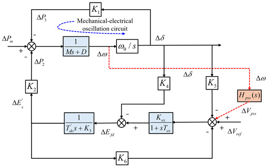
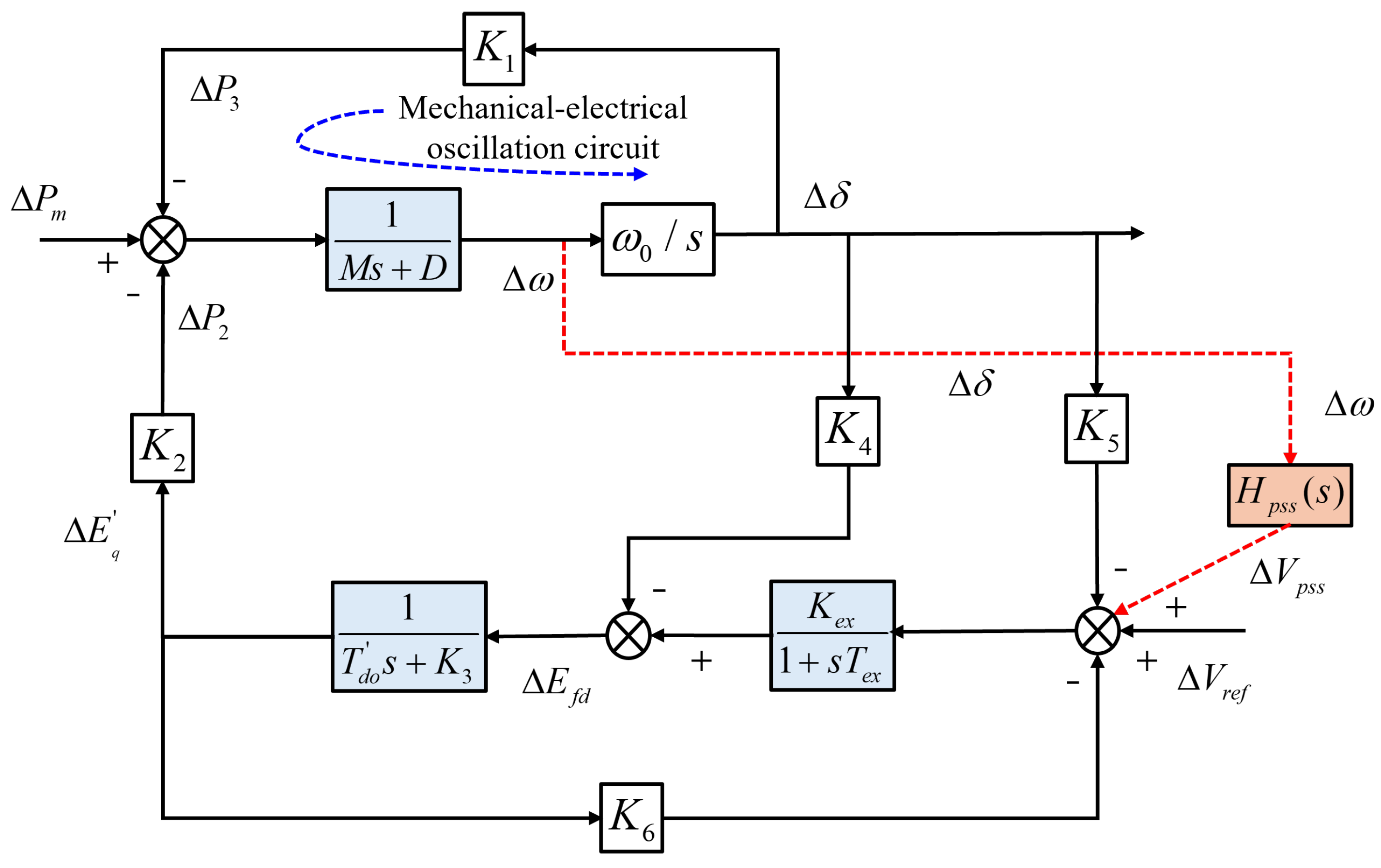
The electromechanical interaction between the synchronous generator and the external power grid is described using a single-machine infinite-bus (SMIB) representation, as shown in Figure 1. This model captures the coupling between rotor motion, electrical power output, and excitation dynamics, which collectively determine the low-frequency oscillation characteristics of the system [15].
Figure 1.
Phillips–Heffron model of synchronous generator.
The rotor motion dynamics are described by the linearized swing equations:
where is the rotor angle deviation, is the rotor speed deviation relative to synchronous speed, H is the inertia constant, D is the damping coefficient, is the mechanical power deviation, and is the electrical power deviation. The mechanical damping coefficient D is assumed constant for small-signal analysis. This simplification provides a tractable representation of the inherent damping contributed by generator friction, load response, and network losses. However, in real power systems, structural and load damping are time-varying and dependent on operating conditions, power flow, and load composition.
The electrical output power is linearized around the operating point as:
where and are linearization coefficients determined by the operating condition and network parameters, and denotes the transient internal electromotive force (EMF) deviation.
To account for the excitation control effect, the generator internal voltage dynamics are represented by:
where is the direct-axis transient open-circuit time constant, is the exciter gain, is the exciter time constant, and is the terminal voltage deviation.
The above equations describe the electromechanical coupling between the generator rotor, excitation system, and the external network. Specifically, the rotor angle deviation affects the electrical output power, while the excitation system influences the internal EMF and thereby modifies the synchronizing torque. This coupling mechanism is the fundamental source of low-frequency oscillatory modes in the generator–grid system and provides the basis for subsequent damping analysis.
2.2. Speed Governing System
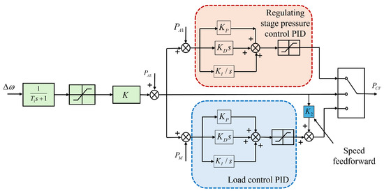
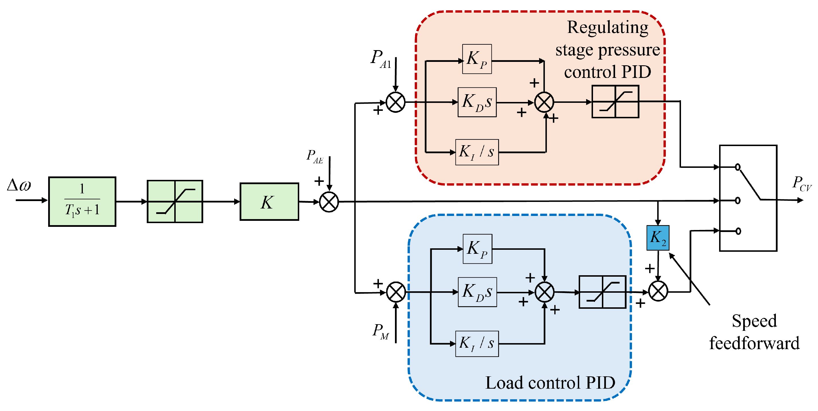
The structure of the speed governing system is shown in Figure 2. It consists of a measurement module, a PID controller, and a feedback loop that regulates turbine input based on frequency deviations [16].
Figure 2.
Transfer function diagram of the speed controller.
As illustrated in Figure 2, the rotor speed deviation is first processed through a measurement block, which is typically modeled as a first-order lag to account for sensing and filtering dynamics [17]:
The PID governor controller is expressed as:
where , and are the proportional, integral, and derivative gains, respectively. This block determines the desired control action based on the measured speed deviation.
The control signal to the electro-hydraulic servo mechanism is then obtained by combining the governor controller and the measurement dynamics:
where the negative sign reflects the inherent negative feedback characteristic of the governor, acting to suppress frequency deviations.
2.3. Servo Mechanism
The electro-hydraulic servo mechanism converts the governor control signal into valve position variations.
As illustrated in [7], the servo system introduces both dynamic lag and inertia due to hydraulic actuation and mechanical movement. It is modeled as a second-order system [18]:
Accordingly, the valve opening deviation is given by:
This representation captures the dominant dynamic delays and inertia associated with hydraulic actuation and valve movement.
2.4. Turbine Power Model
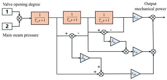
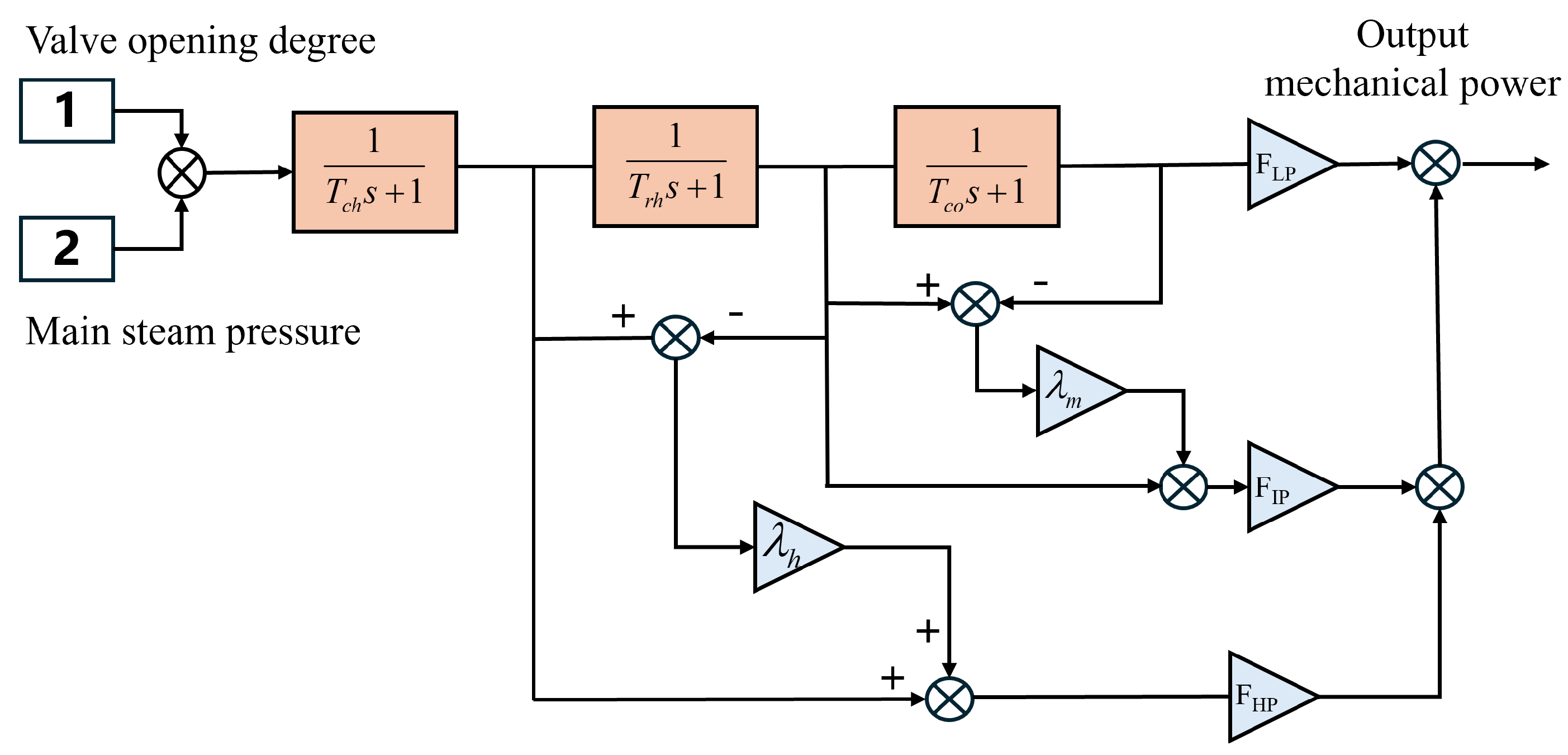
The steam turbine model is depicted in Figure 3, where multiple stages represent the energy conversion process from steam to mechanical power [19].
Figure 3.
The steam turbine model.
As shown in Figure 3, the valve opening determines the steam flow, which then propagates through different turbine stages with distinct time constants. A reheat turbine model is adopted and represented by:
Thus, the mechanical power deviation is expressed as:
This model reflects the multi-stage energy storage and delay characteristics in the high-pressure, intermediate-pressure, and low-pressure sections of the turbine.
2.5. Small Frequency Deviation Amplification
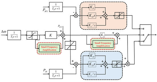
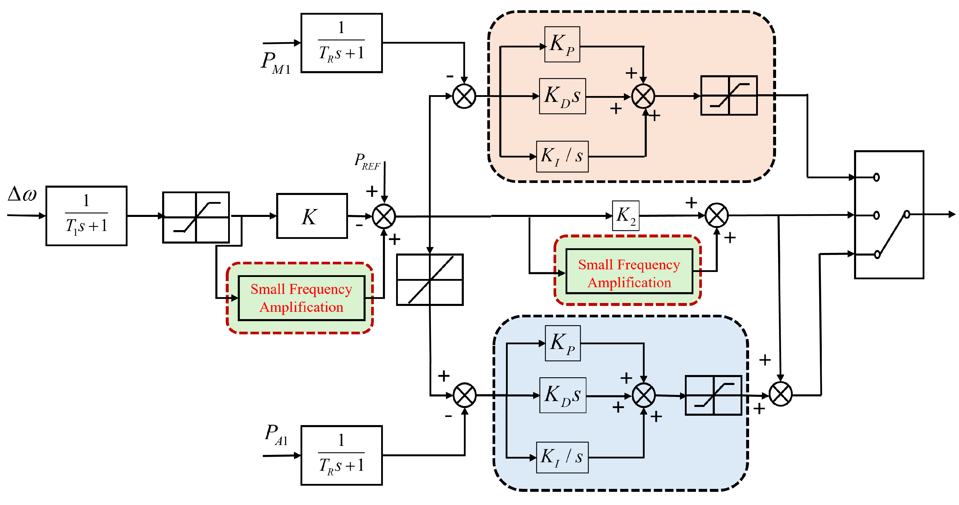
The structure of the small frequency deviation amplification mechanism is shown in Figure 4. This module modifies the conventional droop characteristic by introducing an additional gain in the small frequency deviation region.
Figure 4.
Structure of a thermal power governing system with small frequency deviation amplification.
As illustrated in Figure 4, the frequency deviation is processed through both the conventional droop path and the amplification path. The resulting load reference signal is:
where R is the droop coefficient, is the system frequency deviation, and is the nonlinear, piecewise amplification function implemented in practice.
For small-signal analysis, can be linearized around the operating point:
This linearization assumes that remains sufficiently small such that the amplification function is approximately linear and smooth. The linear approximation allows analytical evaluation of damping characteristics using frequency-domain methods. However, it is important to note that for large frequency deviations, the true piecewise nonlinear nature of becomes significant, and the linearized model may no longer accurately capture the system response. Therefore, the linearized model should be considered valid only within the small deviation range around the nominal operating point.
Substituting into the above equation yields:
This indicates that the amplification mechanism effectively modifies the droop characteristic. The corresponding equivalent droop coefficient can be expressed as:
It can be observed that the introduction of results in a variable effective gain in the frequency control loop, which directly affects the synchronizing torque and damping torque components, thereby influencing LFO characteristics.
Furthermore, to prevent singularity and maintain a positive effective droop, the amplification gain must satisfy: . If , the effective droop , which is physically implausible and would correspond to a marginally stable or unstable operating condition. By enforcing this bound, the model ensures realistic and safe operating conditions for governor operation.
2.6. State-Space Representation
By aggregating all sub-models, the overall system can be expressed in a standard linear state-space form:
where the state vector is defined as:
For comparative analysis, two scenarios are considered:
- Without small frequency deviation amplification:
- With small frequency deviation amplification:
where represents the perturbation of the system state matrix induced by the amplification gain.
The proposed model establishes. The proposed model establishes a unified analytical framework for investigating the influence of small frequency deviation amplification on system dynamic performance. By equivalently representing the nonlinear amplification as a gain modification under small-signal conditions, the model achieves a balance between analytical tractability and physical interpretability, thereby facilitating subsequent eigenvalue analysis and damping sensitivity studies.
3. Damping Torque Analysis of Small Frequency Deviation Amplification
3.1. Principle of Damping Torque Analysis
Damping torque analysis (DTA) is an established method for evaluating the contribution of various control systems to the damping of electromechanical oscillations. The fundamental principle is based on the linearized rotor swing equation:
where H is the inertia constant, D is the natural mechanical damping coefficient, is the incremental mechanical torque, and is the incremental electrical torque.
In the frequency domain, focusing on the oscillation frequency , torque deviations can be decomposed into components aligned with the rotor angle deviation and the rotor speed deviation :
where and are the synchronizing torque coefficients, and and are the damping torque coefficients from the electrical and mechanical sides, respectively.
The total effective damping torque coefficient of the system is . Therefore, a positive electrical damping coefficient () enhances stability, while a positive mechanical damping coefficient () reduces the total system damping, potentially leading to oscillatory instability.
3.2. Mechanical Torque Response of the Governing System
The damping contribution of the governing system originates from the dynamic relationship between the mechanical torque output and the speed deviation. Based on the governor–turbine model developed in Section 2, assuming per-unit values near the operating point such that , the mechanical power deviation in the Laplace domain is:
where represents the equivalent closed-loop transfer function from speed deviation to mechanical power, incorporating the small frequency deviation amplification module.
The primary frequency control law, augmented by the amplification gain designed to improve response in the small deviation region, can be expressed as:
where R is the permanent droop and is the effective proportional gain of the controller. Consequently, the equivalent transfer function is:
Here, represents the combined forward-path transfer function encompassing the governor control logic (), the servo-valve dynamics (), and the turbine steam volume delays ().
3.3. Frequency-Domain Representation and Damping Extraction
To analyze the damping characteristics during low-frequency oscillations (LFOs), the transfer function is evaluated at the dominant oscillation frequency :
Substituting the frequency-domain transfer function into Equation (23) and utilizing Euler’s formula , the mechanical power response can be explicitly expanded as:
To properly separate the damping and synchronizing torque components, we must isolate the terms aligned with and , respectively. From the rotor kinematics in the frequency domain, the relationship between rotor speed and angle is . Consequently, multiplying the speed deviation by j yields . Substituting this relationship into the imaginary part of the mechanical power equation allows us to decompose the torque:
As established in the fundamental damping torque analysis framework (Equation (22)), the component in phase with the speed deviation dictates the mechanical damping torque coefficient. Extracting this component yields:
3.4. Impact of Small Frequency Deviation Amplification on LFO
The expression for reveals the fundamental mechanism by which the governing system interacts with low-frequency oscillations.
The dynamics of the servo system and the steam volumes within the turbine introduce significant phase lag. In the typical frequency range of electromechanical LFOs (0.1 Hz to 2.5 Hz), the phase angle of the forward path usually falls within the range of or depending on the specific turbine time constants.
The mechanical damping coefficient quantifies the contribution of the governor–turbine system to the total damping of electromechanical oscillations. Its value depends on the phase angle of the forward-path transfer function :
Here, represents the phase lag introduced by the servo mechanism and turbine dynamics. The sign of determines the damping effect:
- If , then , which contributes positively to system damping.
- If , then , which acts against natural damping and may reduce total damping, potentially leading to sustained oscillations.
As established in Equation (20), a positive acts in opposition to the natural damping D, effectively injecting energy into the oscillation and reducing the overall system damping margin.
The introduction of the small frequency deviation amplification significantly exacerbates this effect. By defining , the magnitude of the negative damping contribution grows linearly with the amplification gain:
Therefore, while increasing enhances the steady-state primary frequency response, it simultaneously amplifies the adverse dynamic effects caused by the inherent phase lags of the physical turbine system. If is set too high, the term may become large enough to overcome the total electrical and natural mechanical damping (), driving the effective system damping negative and triggering sustained or growing low-frequency oscillations.
4. Simulation Studies
To validate the accuracy of the proposed electromechanical coupling model and to investigate the impact mechanism of small frequency deviation amplification on the damping characteristics of low-frequency oscillations, a time-domain simulation model based on a single-machine infinite-bus (SMIB) system is developed in MATLAB/Simulink R2024b.
4.1. Simulation System and Parameter Settings
The simulation system is based on a typical 350 MW-class supercritical thermal power unit located in the northern region of China. The generator is connected to an infinite bus through a step-up transformer and double-circuit transmission lines. The governing system is equipped with a small frequency deviation compensation module and a sequential valve nonlinear flow characteristic module.
The operating condition is set such that the unit initially operates at approximately 60% of its rated load. Under this condition, the high-pressure (HP) main control valves are located near the switching point with a small valve overlap. In this region, the baseline flow gain reaches its maximum, while the inherent system damping is relatively weak, making it a critical operating point for the occurrence of LFOs.
The simulation system is based on a typical 350 MW-class supercritical thermal power unit connected to an infinite bus. The governing system incorporates small frequency deviation amplification. To ensure reproducibility, all key system parameters used in the MATLAB/Simulink model are summarized in Table A1.
4.2. Model Accuracy Comparison
To demonstrate the necessity and accuracy of the proposed model, comparative simulations are carried out between two models:
- Model A (conventional model): The small frequency deviation compensation module is not considered, and the turbine valve flow characteristic is approximated using a global linearization.
- Model B (proposed model): The small frequency deviation compensation logic is incorporated, and the nonlinear flow characteristics of sequential valves are explicitly modeled.
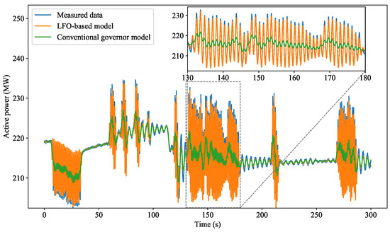
Measured LFO data from an actual 350 MW unit are used for model validation. To ensure the reliability and transparency of the validation process, strict data preparation and parameter identification procedures were implemented. High-precision Phasor Measurement Units (PMUs) installed at the generator step-up transformer were utilized to capture the dynamic responses. The PMUs are GPS-synchronized and configured to record three-phase voltage, current phasors, active power, and frequency at a reporting rate of 50 frames per second (a sampling interval of ). Prior to validation, the raw PMU data was subjected to a zero-phase low-pass Butterworth filter with a cutoff frequency of . This filtering process eliminates high-frequency measurement noise and grid artifacts, cleanly isolating the dominant low-frequency electromechanical modes (typically ). At 10:04, a servo valve blockage in the No. 2 HP control valve caused the valve to be fully closed (forced to 0% opening). At 10:30:42, the unit was switched to DEH power control mode, after which LFOs were triggered. The oscillation lasted from 10:32:13 to 10:35:00, with a power fluctuation range of 205–230 MW and an oscillation frequency of 0.871 Hz.
The PMU sampling interval is 0.02 s. A data segment from sample points 200 to 15,200 (corresponding to to , totaling ) is extracted, including rotor speed and active power, for model validation.
During the oscillation, the No. 2 HP valve remains fully closed. Accordingly, the corresponding flow coefficient in the model is set to zero. Since the flow characteristics of HP valves No. 1 and No. 2 are identical, the closure of valve No. 2 leads to an increased flow through valve No. 1. Therefore, the flow coefficient of valve No. 1 is adjusted to 0.6. The small frequency deviation compensation function is configured consistently with the actual control logic of the unit.
As shown in Figure 5, the simulation results of the proposed model exhibit a high degree of consistency with the measured power oscillation curve when both the small frequency deviation compensation and the nonlinear valve flow modules are incorporated.
Figure 5.
Comparison between measured data and simulation results of the proposed model.
In contrast, the conventional model, which employs a fixed droop coefficient, fails to capture the enhanced frequency regulation capability in the small-deviation region. Furthermore, it neglects the nonlinear characteristics of valve flow, including flow redistribution caused by valve closure and the deterioration of local frequency regulation performance near valve switching points. Consequently, the simulated response of the conventional model shows noticeable discrepancies compared to the measured power oscillations.
Quantitatively, the proposed model achieves a root mean square error (RMSE) of 3.18 MW and a mean absolute percentage error (MAPE) of 1.18%, demonstrating its capability to accurately reproduce the LFO dynamics.
4.3. Impact of Small Frequency Deviation Amplification Gain on Dynamic Characteristics
To quantitatively reveal the impact of small frequency deviation amplification on system oscillatory behavior, eigenvalue analysis is carried out based on the linearized state-space model derived in Section 3. The amplification gain is treated as a key bifurcation parameter, and its influence on system modal characteristics is systematically investigated.
Let the linearized system be expressed as:
where explicitly reflects the dependence of the system dynamics on the amplification gain. The eigenvalues of matrix determine the small-signal stability and damping properties of the system.
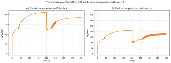
To further quantify the influence of key parameters in the small frequency deviation amplification loop on system damping characteristics, comparative simulations are conducted with the load compensation coefficient (LCC) set to 3 and 4. The corresponding active power responses are shown in Figure 6.
Figure 6.
Comparison of active power oscillations for different load compensation coefficients.
As illustrated in Figure 6, under the operating condition with proportional gain and valve compensation coefficient equal to 5, a disturbance is introduced at .
When , the active power deviation exhibits moderate oscillations following the disturbance. After a short transient period, the oscillation amplitude is effectively bounded within a relatively narrow range, indicating that the system retains a certain level of damping capability.
In contrast, when , the power response rapidly evolves into sustained oscillations with large amplitude. The oscillation envelope does not exhibit any noticeable decay, suggesting a loss of system damping and the onset of instability.
A direct comparison between Figure 6a,b reveals a clear degradation in damping performance as the LCC increases.
For , the oscillations begin to decay or remain weakly damped after approximately , indicating that the system still possesses a positive damping margin.
However, for , the system exhibits typical low-frequency oscillation characteristics over the interval of . The oscillation amplitude remains large and essentially constant, with no observable attenuation. This behavior indicates that the system has transitioned from a stable or weakly damped state to a sustained oscillatory (marginally or negatively damped) condition.
These results clearly demonstrate that increasing the load compensation coefficient can drive the system from a stable regime into oscillatory instability.
The above phenomenon can be rigorously interpreted using the damping torque analysis (DTA) framework.
From the perspective of control structure, increasing the load compensation coefficient effectively enhances the equivalent proportional gain of the governing system in the small frequency deviation region. The mechanical damping torque contributed by the governor–turbine system can be expressed as:
where represents the aggregated frequency response of the servo mechanism and turbine stages, and denotes its phase characteristic at the oscillation frequency .
Due to the inherent energy storage and transport delays in the steam turbine as well as the dynamic lag in the actuator system, the phase characteristic typically results in within the low-frequency oscillation range. Under the negative feedback structure of the governor, this leads to an effective negative damping contribution.
As the LCC increases, the equivalent gain is amplified, resulting in a proportional increase in the magnitude of the negative damping torque . When , the amplified negative damping exceeds the inherent mechanical damping and electromagnetic damping of the generator. Consequently, the total system damping becomes negative, causing small disturbances to grow rather than decay, and ultimately leading to sustained power oscillations.
Therefore, the load compensation coefficient plays a critical role in shaping the damping characteristics of the system. While moderate amplification can enhance frequency regulation sensitivity, excessive gain may introduce significant negative damping and trigger low-frequency oscillatory instability. A strict upper bound must be imposed on the LCC based on the physical delay characteristics of the steam turbine (e.g., the reheater time constant, )—specifically restricting for units with large delays—to prevent the phase lag from inducing excessive positive mechanical damping, complemented by strict deadband saturation limits (e.g., ).
While the current study focuses on time-domain simulations and damping torque analysis to evaluate the impact of small frequency deviation amplification, a comprehensive eigenvalue-based modal analysis, including eigenvalue trajectories, damping ratios, and participation factors, is not provided and will be addressed in future work to further quantify the influence of amplification gain on system stability.
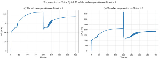
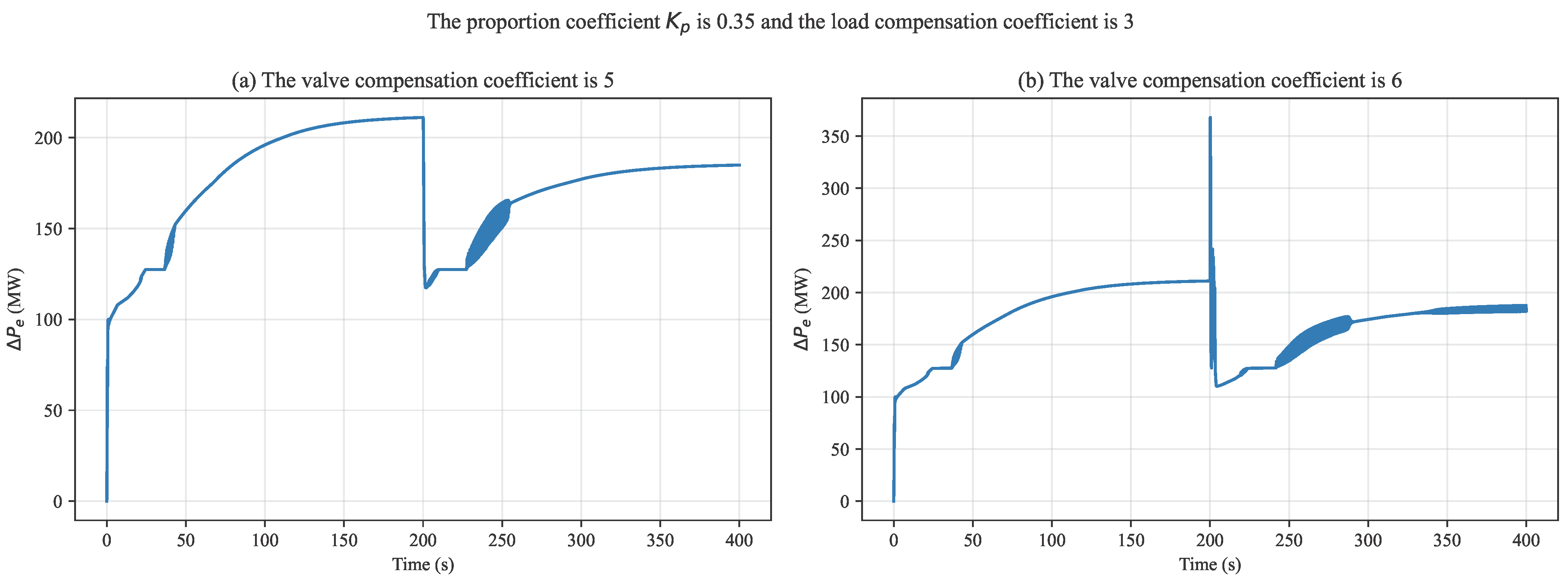
Figure 7 shows the active power responses under different valve compensation coefficients (VCC). The simulations are conducted with proportional gain and load compensation coefficient fixed at 3.
Figure 7.
Active power responses under different valve compensation coefficients.
When , the system exhibits moderate oscillations following the disturbance. The oscillation amplitude remains relatively small and gradually decays over time, indicating a weakly damped or near-critically damped response. The power trajectory is smooth, and no sustained oscillations are observed, suggesting that the system still maintains an acceptable stability margin.
In contrast, when , the system’s dynamic behavior deteriorates significantly. The oscillation amplitude increases substantially after the disturbance and quickly evolves into sustained oscillations with nearly constant amplitude. The absence of attenuation in the oscillation envelope indicates that the system damping has been severely weakened, and the system may have entered a negatively damped regime.
From a mechanism perspective, increasing the valve compensation coefficient enhances the sensitivity of the governing system to the nonlinear valve flow characteristics. This leads to more pronounced variations in the equivalent gain during valve movement, especially near valve switching regions or flow characteristic inflection points. As a result, additional phase lag is introduced into the mechanical power response.
Considering the inherent delays associated with steam turbine dynamics and actuator systems, the accumulated phase lag can significantly reduce the effective damping torque provided by the governor and may even result in a negative damping contribution. When the valve compensation gain becomes excessively large, this negative damping effect is amplified, causing the system to transition from a stable or weakly damped condition to sustained oscillatory behavior.
The VCC should be dynamically scheduled according to the actual operating conditions of the valves; in particular, near valve switching points or flow characteristic inflection points where the inherent system flow gain is critically high, the VCC must be strictly restricted (e.g., reduced to 1.0) to avert low-frequency oscillations triggered by the superposition of nonlinear gains.
Therefore, while the valve compensation mechanism can improve local regulation sensitivity, excessive amplification may amplify the adverse effects of valve nonlinearity and dynamic lag. Proper tuning of the valve compensation coefficient is essential to balance dynamic performance and system stability.
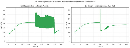
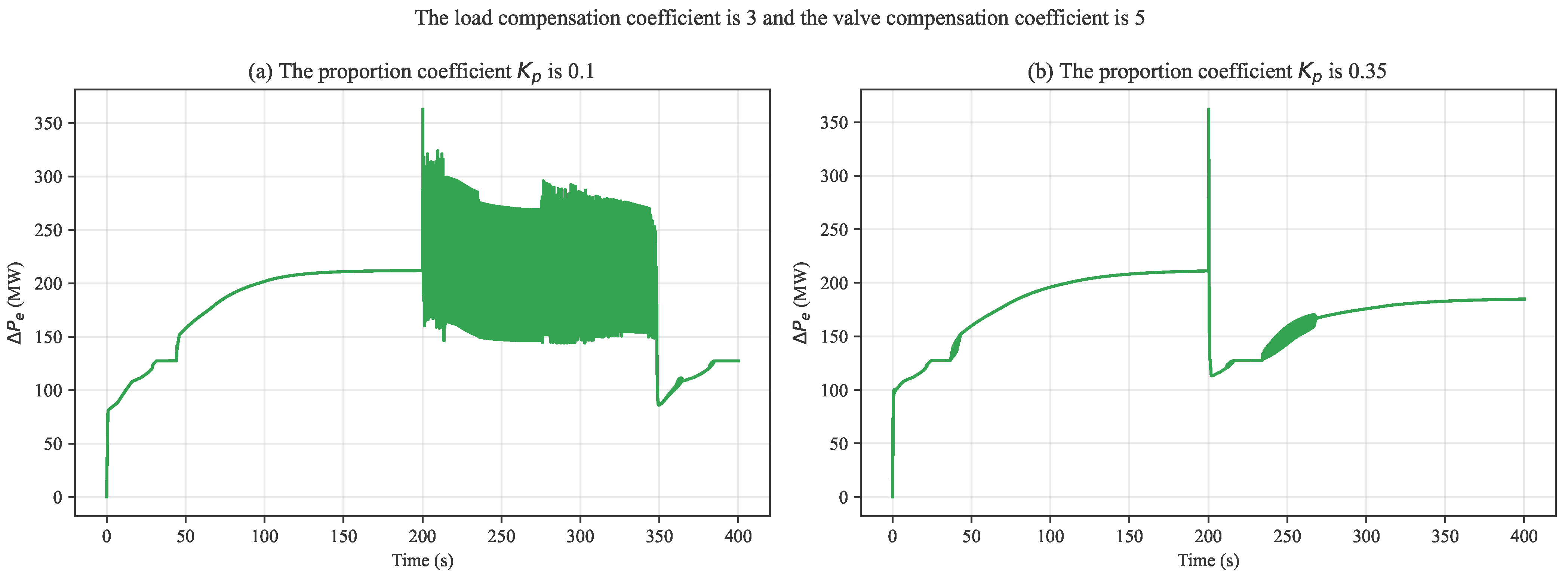
Building upon the previous analysis of load and valve compensation effects, the influence of the proportional gain on system dynamic behavior is further investigated. The simulations are conducted with the load compensation coefficient set to 3 and the valve compensation coefficient fixed at 5, as shown in Figure 8.
Figure 8.
Impact of the proportional gain on low-frequency oscillations.
When , the system exhibits pronounced low-damping oscillations following the disturbance. The oscillation amplitude is relatively large and decays slowly, indicating insufficient frequency regulation capability and weak damping performance.
As increases to 0.35, the oscillation amplitude is significantly reduced, and the response converges much faster to the steady state. This demonstrates a substantial improvement in system damping.
In comparison with the effects of load and valve compensation coefficients, the proportional gain primarily influences the overall feedback strength of the governing system. A small leads to insufficient mechanical power response to frequency deviations, making it difficult to suppress oscillations. Increasing enhances the frequency regulation capability and damping torque. However, excessively large proportional gain may introduce additional phase lag and reduce stability margins, indicating the need for proper parameter tuning.
Overall, the eigenvalue analysis provides a clear theoretical explanation for the damping improvement observed in time-domain simulations. It confirms that the small frequency deviation amplification mechanism plays a critical role in reshaping the system modal characteristics and offers a quantitative basis for parameter tuning and stability enhancement. We note that potential interactions among these parameters may further influence system damping and oscillation characteristics. A simultaneous multi-parameter sensitivity analysis is left for future work, which would provide a more comprehensive understanding of coupled parameter effects and support optimal tuning of control settings.
5. Conclusions
This paper investigates the impact mechanism of small frequency deviation amplification on low-frequency oscillations in thermal power units. A refined electromechanical coupled model of the governing system is established, incorporating both the amplification mechanism and nonlinear valve flow characteristics. Based on the derived linearized model, the effect of amplification gain on system damping is analyzed using the damping torque analysis method. The results reveal that the amplification mechanism effectively increases the sensitivity of mechanical power to frequency deviations, but may also introduce negative damping due to inherent phase lag in the turbine and actuator dynamics. Simulation results further demonstrate that the amplification gain has a significant influence on system dynamic performance. Appropriate parameter settings can improve damping and enhance frequency regulation capability, whereas excessive gain may reduce damping and trigger sustained oscillations. The main limitations are its reliance on the single-machine infinite-bus approximation and linearized small-signal assumptions, as well as the lack of consideration for multi-generator interactions and renewable energy integration. To address these, future research will extend the model to multi-machine systems and high-renewable grids, integrate eigenvalue-based modal analysis and multi-parameter sensitivity studies, and validate with high-resolution PMU data to improve practical applicability.
Author Contributions
Conceptualization, M.Z. and Y.W.; methodology, Y.S.; software, Z.Z.; validation, W.G.; resources, M.Z.; data curation, D.L.; writing—original draft preparation, M.Z. and Y.S.; writing—review and editing, Y.S.; visualization, Y.S.; supervision, Y.S.; project administration, M.Z.; funding acquisition, Y.S. All authors have read and agreed to the published version of the manuscript.
Funding
This work was supported by the National Natural Science Foundation of China under Grant No. 62503199, the Fundamental Research Funds for the Central Universities under Grant No. JUSRP202501133a and Science and Technology Project of State Grid-Corporation of China.
Data Availability Statement
The data presented in this study may be obtained from the corresponding author upon request.
Conflicts of Interest
Authors Mujie Zhang, Yajun Wu, and Dongsheng Li are employed by Central China Branch of State Grid Corporation of China. The remaining authors declare that the research was conducted in the absence of any commercial or financial relationships that could be construed as a potential conflict of interest. The Central China Branch of State Grid Corporation of China had no role in the design of the study; in the collection, analyses, or interpretation of data; in the writing of the manuscript, or in the decision to publish the results.
Abbreviations
The following abbreviations are used in this manuscript:
| LFO | Low-Frequency oscillation | |
| SMIB | Single-machine infinite-bus | |
| PID | Proportional–integral–derivative | |
| DTA | Damping torque analysis | |
| HP | High pressure | |
| LCC | Load compensation coefficient | |
| VCC | valve compensation coefficient | |
| PMU | Phasor measurement unit | |
| Nomenclature | ||
| Symbol | Description | Unit |
| Variables | ||
| Rotor angle deviation | rad | |
| Rotor speed deviation relative to synchronous speed | p.u. | |
| Mechanical power deviation | MW | |
| Electrical power deviation | MW | |
| Transient internal EMF deviation | p.u. | |
| Terminal voltage deviation | p.u. | |
| Load reference signal | MW | |
| Parameters | ||
| H | Generator inertia constant | s |
| D | Natural mechanical damping coefficient | p.u. |
| R | Droop coefficient | p.u. |
| Equivalent droop coefficient | p.u. | |
| Small frequency deviation amplification gain | p.u. | |
| Servo gain | p.u. | |
| Linearization coefficients for electrical power | MW/rad, MW/p.u. | |
| Total effective damping torque coefficient | p.u. | |
| Electrical and mechanical damping coefficients | p.u. | |
| Exciter gain | p.u. | |
| Measurement lag time constant | s | |
| Servo system time constants | s | |
| Direct-axis transient open-circuit time constant | s | |
| Exciter time constant | s | |
| Time constants of turbine stages | s | |
| Dominant low-frequency oscillation frequency | Hz | |
| Proportional, integral, derivative gains of governor | – |
Appendix A
Table A1.
System Parameters Used in MATLAB/Simulink Simulations.
References
- Huang, W.; Zhai, S.; Lu, X.; Zhang, X.; Liu, Y.; He, W.; Fang, Y. Ultra-Low Frequency Oscillation in a Thermal Power System Induced by Doubly-Fed Induction Generators with Inertia Control. Processes 2025, 13, 1368. [Google Scholar] [CrossRef] [Scilit]
- Wang, Y.; Chen, S.; Yang, M.; Liao, P.; Xiao, X.; Xie, X.; Li, Y. Low-frequency oscillation in power grids with virtual synchronous generators: A comprehensive review. Renew. Sustain. Energy Rev. 2025, 207, 114921. [Google Scholar] [CrossRef] [Scilit]
- Prasertwong, K.; Mithulananthan, N.; Thakur, D. Understanding low-frequency oscillation in power systems. Int. J. Electr. Eng. Educ. 2010, 47, 248–262. [Google Scholar] [CrossRef] [Scilit]
- Yang, M.; Wang, Y.; Guerrero, J.M. Impact of reactive power control on low-frequency oscillation of virtual synchronous generators. IEEE Trans. Power Syst. 2025, 40, 3604–3607. [Google Scholar] [CrossRef] [Scilit]
- He, P.; Fang, Q.; Jin, H.; Ji, Y.; Gong, Z.; Dong, J. Coordinated design of PSS and STATCOM-POD based on the GA-PSO algorithm to improve the stability of wind-PV-thermal-bundled power system. Int. J. Electr. Power Energy Syst. 2022, 141, 108208. [Google Scholar] [CrossRef] [Scilit]
- Yin, J.; Zhang, G.; Jia, B. Optimization of Heating Unit Primary Frequency Regulation Based on Small Frequency Deviation Assessment of Power Grid. J. Inn. Mong. Electr. Power 2023, 40, 78–82. [Google Scholar]
- Hong, F.; Ji, W.; Pang, Y.; Hao, J.; Du, M.; Fang, F.; Liu, J. A new energy state-based modeling and performance assessment method for primary frequency control of thermal power plants. Energy 2023, 276, 127594. [Google Scholar] [CrossRef] [Scilit]
- Rudnik, V.E.; Ufa, R.A.; Malkova, Y.Y. Analysis of low-frequency oscillation in power system with renewable energy sources. Energy Rep. 2022, 8, 394–405. [Google Scholar] [CrossRef] [Scilit]
- Obaid, Z.A.; Cipcigan, L.M.; Abrahim, L.; Muhssin, M.T. Frequency control of future power systems: Reviewing and evaluating challenges and new control methods. J. Mod. Power Syst. Clean Energy 2019, 7, 9–25. [Google Scholar] [CrossRef] [Scilit]
- Senyuk, M.; Elnaggar, M.F.; Safaraliev, M.; Kamalov, F.; Kamel, S. Statistical method of low frequency oscillations analysis in power systems based on phasor measurements. Mathematics 2023, 11, 393. [Google Scholar] [CrossRef] [Scilit]
- Tapin, L.; Mehta, R.K. Low Frequency Oscillations in Power Systems: A Review. Seventh Sense Res. Group Int. Electr. Electron. Eng. 2014, 1, 6–17. [Google Scholar]
- Ghorbaniparvar, M. Survey on forced oscillations in power system. J. Mod. Power Syst. Clean Energy 2017, 5, 671–682. [Google Scholar] [CrossRef] [Scilit]
- Xu, Y.; Gu, Z.; Sun, K.; Xu, X. Understanding a type of forced oscillation caused by steam-turbine governors. IEEE Trans. Energy Convers. 2020, 35, 1719–1722. [Google Scholar] [CrossRef] [Scilit]
- Shen, Y.; Li, Z.; Ma, J.; Wang, L.; Su, N.; Song, J. Interaction energy-based power coupling oscillation analysis and suppression of grid-forming converter connected system. Int. J. Electr. Power Energy Syst. 2025, 166, 110558. [Google Scholar] [CrossRef] [Scilit]
- Xu, B.; Zhang, J.; Egusquiza, M.; Chen, D.; Li, F.; Behrens, P.; Egusquiza, E. A review of dynamic models and stability analysis for a hydro-turbine governing system. Renew. Sustain. Energy Rev. 2021, 144, 110880. [Google Scholar] [CrossRef] [Scilit]
- Li, C.; Zhou, J. Parameters identification of hydraulic turbine governing system using improved gravitational search algorithm. Energy Convers. Manag. 2011, 52, 374–381. [Google Scholar] [CrossRef] [Scilit]
- Lu, S.; Wu, M.; Liu, J.; Wang, H.; Yang, L.; Liu, Q.; Yang, J.; Sui, Y. Low-frequency oscillation damping strategy for power system based on virtual dual-input power system stabilizer. IET Renew. Power Gener. 2024, 18, 4439–4452. [Google Scholar] [CrossRef] [Scilit]
- Li, H.; Chen, D.; Zhang, H.; Wang, F.; Ba, D. Nonlinear modeling and dynamic analysis of a hydro-turbine governing system in the process of sudden load increase transient. Mech. Syst. Signal Process. 2016, 80, 414–428. [Google Scholar] [CrossRef] [Scilit]
- Wang, H.; He, H.; Liu, M.; Dong, H.; Lu, S.; Zhang, G.; Yang, J. Influence mechanism and VPSS method of VSG for low-frequency oscillation of power system. In Proceedings of the 2023 8th Asia Conference on Power and Electrical Engineering (ACPEE); IEEE: Piscataway, NJ, USA, 2023; pp. 2372–2376. [Google Scholar]
Disclaimer/Publisher’s Note: The statements, opinions and data contained in all publications are solely those of the individual author(s) and contributor(s) and not of MDPI and/or the editor(s). MDPI and/or the editor(s) disclaim responsibility for any injury to people or property resulting from any ideas, methods, instructions or products referred to in the content. |
© 2026 by the authors. Licensee MDPI, Basel, Switzerland. This article is an open access article distributed under the terms and conditions of the Creative Commons Attribution (CC BY) license.