Abstract
This paper proposes a finite-time adaptive backstepping active suspension control strategy, integrating command filtering and composite learning, to address the degradation of ride comfort and attitude stability in heavy-duty vehicles caused by shifting loads and harsh roads. First, a nonlinear dynamic vehicle model is established, treating multi-source complex disturbances as a single lumped disturbance and accounting for suspension stiffness and damping nonlinearities. To stabilize the body attitude, a tri-axis controller governing the vertical, pitch, and roll motions is developed, incorporating the practical physical constraints of actuators. By employing a composite learning Radial Basis Function neural network, the controller achieves smooth approximation and precise compensation of lumped disturbances, significantly enhancing the system’s active disturbance rejection performance under complex excitations. Furthermore, the finite-time stability of the closed-loop system is rigorously proven using Lyapunov stability theory. Finally, the strategy is evaluated under a 40% load mass mismatch and continuous random road excitations. Results indicate that the proposed strategy effectively curbs the deterioration of suspension nonlinearities during overloads, ensuring smoother dynamic transitions across all three axes. Compared to conventional backstepping control, the proposed approach reduces the root mean square values of vertical, pitch, and roll accelerations by 19%, 13%, and 35%, respectively. Ultimately, this framework effectively improves vehicle stability and disturbance rejection, providing a robust reference for heavy-duty vehicle chassis control.
1. Introduction
Heavy-duty vehicles frequently operate on unstructured terrains, such as mines, construction sites, and remote disaster zones [1,2]. Driven by growing demands in engineering and emergency rescue operations, these vehicles increasingly navigate complex off-road environments [3]. The severe vibrations and jolts generated by harsh road conditions not only degrade the driver’s ride experience [4,5], but also threaten overall vehicle stability. Heavy-duty vehicles frequently experience massive load shifts, such as transitioning to full capacity or operating under severe overload. Combined with a relatively high center of gravity, this causes drastic body attitude fluctuations on continuously bumpy roads. This poses a severe challenge to the vehicle’s roll and pitch stability, particularly during extreme maneuvers [6,7].
As the core force-transmitting hub between the chassis and the road, the suspension system serves two critical functions. First, it stably supports the sprung mass to maintain a proper body attitude. Second, it utilizes elastic and damping elements to absorb road excitations, thereby reducing the shock transmitted to the chassis and cabin [8,9]. Therefore, the comprehensive performance of the suspension system is crucial for ensuring both the ride comfort and driving safety of heavy-duty vehicles.
In recent years, performance optimizations for various suspension systems have been extensively researched. Passive and semi-active suspensions face inherent bottlenecks in handling complex, shifting conditions due to structural constraints or limited external energy inputs [10,11]. In contrast, active suspensions can dynamically adjust actuator outputs in real time via external energy. They show significant potential in actively rejecting road disturbances and regulating body attitude, emerging as a research hotspot in vehicle engineering [12]. In this direction, valuable explorations have been made using modern control theories like Linear Quadratic Regulators, intelligent control algorithms including fuzzy logic and deep learning, state observer designs, and comprehensive performance evaluation methods [13,14,15,16,17,18,19]. These studies confirm that a well-designed active suspension control strategy can effectively improve the dynamic performance of vehicles, laying a solid foundation for engineering applications.
As research deepens, the inherent nonlinear characteristics of active suspension systems have drawn increasing attention. These nonlinearities primarily stem from actuator output limitations, the nonlinear responses of suspension stiffness and damping, and the cross-coupling of multi-axis spatial motions [20,21]. To tackle these challenges, rich theoretical support has been provided in nonlinear dynamic modeling and disturbance rejection [22,23,24,25,26]. Among various control methods, sliding mode control (SMC) is particularly effective against matched uncertainties and provides strong robustness, yet its discontinuous switching mechanism typically imposes higher demands on chattering suppression in practice [26]; model predictive control (MPC) can explicitly handle system constraints and multivariable optimization, but its online computational demand is often high [27,28]. In this context, backstepping is widely adopted due to its structural advantages in handling cascaded nonlinear systems [29]. By integrating backstepping with sliding mode control, adaptive theory, and neural network technologies, existing studies have significantly improved system robustness against parameter perturbations and approximated unmodeled dynamics [30,31,32]. However, in heavy-duty scenarios featuring a combination of massive load shifts and continuous complex excitations, traditional backstepping often suffers from heavy computational burdens caused by repeated differentiations. Meanwhile, active suspensions face mixed disturbances from macroscopic load biases and high-frequency road noise. Under these conditions, it remains an open challenge to guide neural networks to learn smoothly online while maintaining both compensation accuracy and dynamic stability.
Although existing nonlinear active suspension control methods have achieved significant results, specialized heavy-duty vehicles present specific engineering bottlenecks that require targeted research. Taking mobile cranes as an example, they frequently mount varying counterweights and payloads due to distinct lifting conditions, while routinely operating on harsh road terrains. To address the composite disturbances stemming from substantial load variations and continuous complex road excitations, this paper proposes a finite-time adaptive backstepping active suspension control strategy integrating command filtering and frequency-decoupled composite learning. The specific content is organized as follows: First, a 7-degree-of-freedom (7-DOF) nonlinear dynamic model for heavy-duty vehicles is established to capture both body attitude and unsprung mass dynamics. This model fully accounts for suspension stiffness and damping nonlinearities and unifies complex disturbances from mass mismatch and road excitations into a single lumped disturbance. Second, a controller governing the vertical, pitch, and roll axes is designed. By incorporating command filtering and a second-order anti-windup auxiliary system, the computational burden and actuator saturation constraints are effectively handled. Additionally, a prediction-error-based composite learning Radial Basis Function (RBF) neural network is introduced to estimate and compensate for the lumped disturbance online, mitigating overfitting to high-frequency noise. The finite-time stability of the closed-loop system is rigorously proven using Lyapunov theory. Finally, comparative simulations are conducted under a 40% load mass mismatch and continuous random road excitations. The validation results demonstrate that the proposed control architecture effectively curbs suspension nonlinear deterioration and ensures smoother dynamic transitions of the body attitude. By successfully improving both attitude maintenance and vibration isolation, this approach provides a viable theoretical and practical reference for heavy-duty vehicle chassis control under complex conditions.
2. Nonlinear Dynamics Modeling
To accurately reflect the driving characteristics of heavy-duty vehicles under harsh conditions, a 7-DOF nonlinear full-vehicle dynamics model is established, and its system structure is illustrated in Figure 1. This model encompasses the vertical, pitch, and roll motions of the vehicle body, along with the vertical motions of the four wheels. A right-handed spatial coordinate system is adopted. The dynamic equations are formulated around the origin, which is defined as the center of gravity of the vehicle body in its static equilibrium position. The model focuses exclusively on translational and spatial rotational dynamics, excluding wheel rolling and sliding.
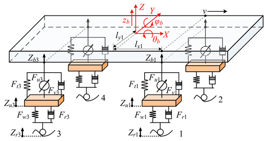
Figure 1.
The 7-DOF nonlinear dynamic model of the heavy-duty vehicle.
Let , , and denote the vertical displacement, pitch angle, and roll angle of the vehicle body, respectively. Based on the spatial kinematics of rigid bodies, the vertical displacement at the articulation point between the -th wheel (, corresponding to front-right, front-left, rear-right, and rear-left) and the vehicle body is expressed as Equation (1):
where and represent the longitudinal and lateral geometric distances from the center of the -th suspension to the pitch and roll axes of the vehicle body, respectively. Assuming represents the vertical displacement of the -th unsprung mass, the dynamic suspension deflection for each unit is defined in Equation (2):
Each suspension is abstracted as a spring-damper model, operating in parallel with an actuator used for active control (with an output force denoted as ). Considering the strong nonlinear characteristics of heavy-duty suspensions, the passive resultant force of the -th suspension is the vector sum of the total elastic force and damping force , uniformly expressed as Equation (3):
where and denote the nominal linear stiffness and nominal linear damping of the suspension, respectively. The nonlinear stiffness term in Equation (3) is given by Equation (4):
where is the cubic nonlinear stiffness coefficient. The nonlinear damping term is formulated as Equation (5):
where and are the nonlinear damping coefficients. Such a damping model, incorporating absolute value and square root terms, more accurately characterizes the asymmetric fluid dynamic properties exhibited by heavy-duty shock absorbers under varying piston velocities.
Under low-speed, harsh off-road conditions, given that vertical disturbances are relatively more pronounced and the road excitation remains complex after transmitting through the tire nonlinearities, the tire is simplified to a vertical linear model, with its nonlinear dynamics absorbed into the road excitation. Let be the road input displacement at the -th wheel; the total force exerted by the ground on the tire consists of the tire stiffness force and damping force , as shown in Equation (6):
where and are the equivalent radial stiffness and damping coefficients of the tires, respectively. Based on the Newton-Euler equations, the multi-degree-of-freedom force balance for the sprung and unsprung masses is governed by Equation (7):
In Equation (7), represents the total body mass, and are the pitch and roll moments of inertia, and represents the -th unsprung mass. is the total vertical force provided by the -th suspension system. The specific form of the transformation matrix is shown in Equation (8):
Six variables are selected as the state variables of the body system: the vertical state , pitch state , and roll state .
To facilitate controller design, the equivalent relative displacements of the -th suspension in each motion channel are defined. These coupling displacements are given by Equation (9):
Based on this, the dynamic suspension deflection is decomposed into the sum of the primary motion and the coupling motions. By extracting the nominal linear terms and isolating the nonlinearities and unknown disturbances, the state-space equations are obtained, as shown in Equation (10) through Equation (12):
Vertical ( channel):
Pitch ( channel):
Roll ( channel):
The actual control inputs for each channel are defined as , , and . The analytical expressions for the lumped disturbances are detailed in Equation (13) to Equation (15):
The terms on the right-hand sides of the above equations correspond sequentially to: the nonlinear internal forces of the suspension, the cross-coupling forces transmitted by road excitations, the parameter deviations caused by mass variations, and the external unknown bounded disturbances . The lumped disturbance terms serve as a comprehensive aggregation of all hard-to-model nonlinearities, parameter variations, and unmodeled perturbations, which will be uniformly approximated online by the composite learning RBF neural network in the subsequent control logic.
3. Controller Design
Before detailing the controller design, the following reasonable assumptions are established for the vehicle system:
Assumption 1.
The desired tracking trajectories for each motion channel (e.g., ) and their time derivatives up to the second order are continuous and bounded.
Assumption 2.
The external unknown time-varying disturbances () induced by harsh road conditions are bounded, satisfying , where are unknown positive constants.
The derivation in this section, as well as the subsequent stability proof, will be demonstrated using the vertical motion ( channel) as an example.
3.1. Input Saturation and Second-Order Anti-Windup Auxiliary System
Because the actuator outputs are physically constrained, the saturation model is expressed by Equation (16):
A saturation error is defined as . To prevent error accumulation, a second-order anti-windup auxiliary system is introduced, as shown in Equation (17):
When the control channel is , the corresponding auxiliary state indices are . Here, represents the control gain of the corresponding channel (e.g., ), and are positive design parameters.
3.2. Preparatory Lemmas
Lemma 1.
For any continuous nonlinear function defined over a compact set , there exists an RBF neural network that can approximate it with high precision, expressed as . Here, is the network input vector, is the ideal weight matrix, is the Gaussian basis function vector, and is the bounded approximation error satisfying ().
In this paper, the input vectors of the RBF networks for the three channels are defined as the respective system state variables: , , and .
Lemma 2.
To circumvent the “explosion of complexity” caused by repeated analytical differentiations in traditional backstepping, a second-order command filter is introduced as Equation (18):
where and are the natural frequency and damping ratio, respectively. With properly chosen parameters, the filter outputs and can approximate the virtual control law and its derivative in finite time with bounded errors.
Lemma 3.
For any real variables and a fractional power (where and are odd positive integers), the following specific fractional-power inequality scaling relationship holds: where and are specific positive constants. This lemma provides a crucial scaling foundation for proving the finite-time convergence of the adaptive weights.
3.3. Vertical Finite-Time Composite Learning Controller Design
The position tracking error is defined as , and the velocity error as . A compensated tracking error is designed as , with its time derivative being .
By differentiating , the vertical virtual control law is obtained, as shown in Equation (19):
where and are positive feedback control gains. Based on the cascading recursive principle, the actual control law , incorporating the error compensation term , is formulated as Equation (20):
where and are positive feedback gains. To facilitate composite learning, a velocity state predictor is further constructed, and the prediction error is defined as , according to Equation (21):
where and are positive predictor feedback gains. Combining this prediction error, a composite adaptive weight update law is designed, as shown in Equation (22):
where are positive adaptive learning parameters.
3.4. Pitch and Roll Channel Controller Results
Following the same logic, the control architecture for the pitch channel is synthesized in Equation (23):
The control architecture for the roll channel is synthesized in Equation (24):
Finally, the aforementioned generalized control inputs are mapped to the four independent suspension actuators in real time through the pseudoinverse of the transformation matrix :
where denotes the actual control force vector of each wheel, and represents the pseudoinverse of the transformation matrix .
3.5. Closed-Loop System Stability Analysis
Theorem 1.
By applying the proposed control architecture, it is guaranteed that all internal signals of the closed-loop system are semi-globally uniformly ultimately bounded, and the tracking errors will converge to a small neighborhood of the origin within a finite time.
Proof.
A scalar comprehensive Lyapunov function is constructed for the vertical channel, consisting of five energy sub-terms, as expressed in Equation (26):
The individual terms are defined as follows: the auxiliary system sub-term , the position error sub-term , the velocity error sub-term , the prediction error sub-term , and the parameter estimation sub-term .
By differentiating each term with respect to time and applying inequality scaling, Equations (27)–(30) are derived:
During the derivation of Equation (28), the internal cross-coupling terms of the system are canceled out by substituting the control law from Equation (20).
By summing Equation (27) through Equation (30), the difficult-to-handle cross-coupling approximation error terms and are perfectly canceled out by the designed term in the adaptive law. After consolidation, the comprehensive derivative inequality of the system can be expanded as:
In this inequality, the negative definite term , combined with the robust leakage adaptive update law, effectively prevents parameter drift under high-frequency road noise. This theoretically guarantees the semi-globally uniform ultimate boundedness of the neural network estimation weight error , ensuring the convergence and stability of the network weights. Furthermore, it is necessary to clarify the derived scaling parameters: and are specific positive coefficients generated when applying Lemma 3 for the fractional-power inequality scaling of the weight parameters, while is a strictly positive derived constant originating from the derivation of the prediction error bounds. is the comprehensive bounded error term containing saturation errors, approximation boundaries , and the ideal weight constant terms and .
To construct the standard form for finite-time convergence, the minimum coefficient of all linear terms, , and the minimum coefficient of all fractional-order terms, , are defined as follows:
By extracting the common factors, the aforementioned comprehensive derivative inequality can be strictly transformed into a function of the composite Lyapunov function :
Based on finite-time stability theory, this inequality rigorously proves that the system’s tracking errors will inevitably converge to a minimal neighborhood of the origin within a finite time. The proof processes for the pitch and roll directions follow exactly the same logical deduction, universally guaranteeing the finite-time stability of the multi-axis closed-loop vehicle system. This concludes the proof. □
4. Simulation Results and Analysis
4.1. Simulation Conditions and Parameter Setup
To verify the effectiveness of the proposed finite-time adaptive backstepping control strategy based on command filtering and composite learning (CFABC) under complex conditions, a nonlinear dynamic simulation model for heavy-duty vehicles was established, and comparative analyses were conducted against a passive suspension and conventional backstepping control (CBC). It should be noted that, to ensure a rigorous and equitable comparison, the passive suspension baseline uses the exact nominal linear stiffness and damping parameters from Table 1, while retaining the same inherent suspension nonlinearities. Table 1 summarizes the structural parameters, suspension nonlinearities, simulation configurations, and core calibration gains. The controller parameters were tuned stepwise. First, the RBF learning rate was adjusted to capture low-frequency static mass deviations. Then, the linear control gain was reduced to soften the suspension response. Finally, the anti-windup parameters were set according to the physical actuator limits. This procedure yielded a balanced parameter set.

Table 1.
Core Parameters of the Vehicle Simulation Model and Controllers.
To excite nonlinear coupling and reflect harsh operating environments, two severe conditions were configured:
- Massive Load Shifts and Mass Mismatch: The actual sprung mass and moments of inertia are abruptly increased by 40%, reaching 33,600 kg, to test steady-state disturbance rejection under a large gravitational bias.
- Multi-Axis Coupled Random Road Excitations: The vehicle speed is set to 20 km/h under continuous random road excitations featuring a correlation coefficient of 0.60.
4.2. Responses to Continuous Random Excitations
A spatial power spectral density model based on white noise filtering was used to generate road roughness excitations for the front wheels. The time-domain models are described as follows:
where and represent the road inputs; traveling speed km/h; reference spatial frequency ; and roughness coefficient . Correlated white noise sequences are generated using a correlation coefficient . The resulting road inputs, shown in Figure 2, trigger vertical, pitch, and roll motions simultaneously, providing a stringent testing environment.
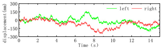
Figure 2.
Continuous random road input excitations for the left and right wheel tracks.
4.3. Vehicle Attitude and Displacement Response Analysis
The variation processes of body vertical displacement and attitude angles, illustrated in Figure 3, intuitively demonstrate the stability of body attitude. In the vertical displacement and attitude responses, facing the 40% sudden load mismatch and continuous random road shocks, CBC exhibits relatively pronounced dynamic fluctuations. The fundamental reason is that it lacks an independent compensation mechanism for load biases, thus being forced to rely on higher linear feedback gains to forcefully suppress suspension deflection and maintain body height. In contrast, CFABC demonstrates superior dynamic smoothness. Because the neural network steadily compensates for the macroscopic static load bias online, the fundamental feedback layer is permitted to adopt lower flexible gains. Consequently, the dynamic transitions of the vehicle body become much smoother, effectively narrowing the amplitude range of the fluctuations and suppressing the rigid abrupt changes observed under CBC. This safeguards the attitude stability of the heavy-duty vehicle.
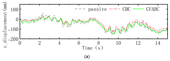
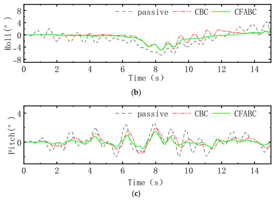
Figure 3.
Comparison of vehicle body attitude responses under passive suspension, CBC, and CFABC strategies: (a) Vertical displacement comparison; (b) Roll angle comparison; (c) Pitch angle comparison.
4.4. Ride Comfort and Acceleration Response Analysis
Vehicle body acceleration is the primary metric for evaluating ride comfort. Figure 4 compares the tri-axis acceleration curves under the passive suspension and the two control strategies. Under harsh excitations, CFABC effectively reduces the overall amplitudes of acceleration peaks. The reason for this phenomenon is that under a mass mismatch, the working point of CBC is forced to shift toward the nonlinear hardening region. Compounded by its highly rigid feedback gain set to maintain ride height, high-frequency road shocks are amplified and transmitted to the vehicle body. Conversely, CFABC utilizes the RBF network to compensate for the gravitational bias online, allowing the suspension to operate within a linear soft region with lower stiffness. Meanwhile, lower basic feedback gains combined with command filtering technology jointly reduce the transmission of vibrations to the vehicle body. Quantitatively, CFABC reduces the root mean square (RMS) values of vertical, pitch, and roll accelerations by 19%, 13%, and 35%, respectively. This confirms that improving the suspension working region via composite adaptation is an effective method to enhance ride comfort. Furthermore, for heavy-duty vehicles with a high center of gravity and substantial load variations, suppressing pitch and roll accelerations goes beyond ride comfort alone. High angular accelerations may lead to considerable dynamic load transfers among the tires. By curbing these fluctuations, the proposed tri-axis control helps maintain consistent tire grip and limits excessive attitude deviations. This directly contributes to reducing rollover risks and enhancing overall driving safety.
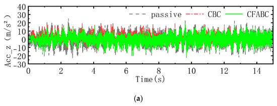
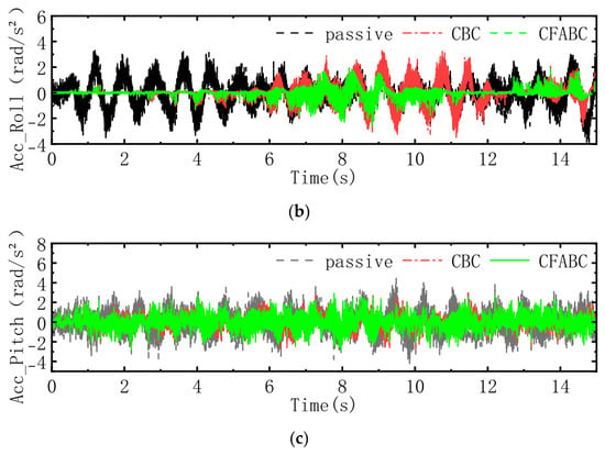
Figure 4.
Comparison of vehicle body acceleration responses under passive suspension, CBC, and CFABC strategies: (a) Vertical acceleration comparison; (b) Roll acceleration comparison; (c) Pitch acceleration comparison.
4.5. Verification of Internal Mechanisms and Learning Processes
To elucidate the operational mechanism of CFABC, Figure 5 compares the theoretical lumped disturbance with the online estimated output. The true disturbance consists of a low-frequency gravitational bias, high-order harmonic forces from suspension nonlinearities, and multiplicative residuals from the mass mismatch.
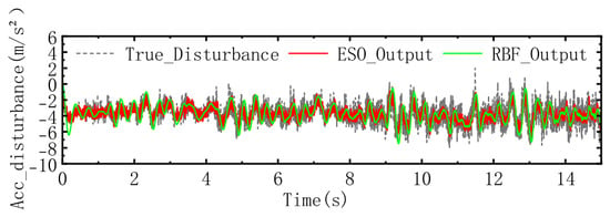
Figure 5.
Online estimation and tracking performance of the RBF neural network on the lumped disturbance.
To provide a baseline, a classic Linear Extended State Observer (LESO) is introduced. To ensure the LESO can respond adequately to the steady-state bias caused by the 40% overload and reach an approximation amplitude comparable to the RBF network, its observer bandwidth is set to a relatively high value ( rad/s). The comparative results indicate that the LESO can also present satisfactory disturbance tracking performance; however, high-frequency noise is simultaneously introduced.
In contrast, the composite learning RBF network demonstrates effective frequency-domain separation. In the initial stage, network weights update rapidly to estimate and compensate for the constant bias caused by overloading. Thereafter, the network output maintains stability against high-frequency fluctuations, which helps avoid parameter drift and the undesirable propagation of high-frequency noise into the control law.
These results verify that the proposed algorithm achieves smooth approximation and reliable compensation of lumped disturbances. Since the RBF network primarily handles the static bias compensation, the feedback control layer can address dynamic shocks with a more flexible, smaller gain, thereby improving the overall active disturbance rejection performance of the system.
5. Conclusions
This study establishes a robust chassis control framework for heavy-duty vehicles to mitigate the severe dynamic deterioration caused by shifting loads and continuous random road excitations. The effectiveness of this strategy is rigorously verified through theoretical derivations and nonlinear dynamic simulations. The results show that the composite learning RBF neural network achieves smooth and accurate compensation of lumped disturbances, particularly for the steady-state gravitational bias caused by overloading. Regarding parameter configuration, because the neural network undertakes the task of static bias compensation, the basic feedback control layer is permitted to adopt a lower, flexible gain, significantly enhancing the system’s active disturbance rejection performance under complex excitations. Simulation results demonstrate that this control architecture effectively prevents the suspension working point from shifting toward the nonlinear hardening region, ensuring smoother dynamic transitions of the tri-axis body attitude under asymmetric excitations. In terms of quantitative ride smoothness indicators, compared to conventional backstepping control, the proposed strategy reduces the RMS values of vertical, pitch, and roll accelerations by 19%, 13%, and 35%, respectively. In summary, the discussed control architecture effectively improves the attitude stability and ride comfort of heavy-duty vehicles, providing a viable theoretical and practical reference for comprehensive chassis control under complex conditions.
Author Contributions
Establishment of the nonlinear vehicle dynamic model and derivation of the control algorithm, W.Z.; writing and programming of the MATLAB simulation code, W.Z. and Y.W.; simulation testing and image and data processing, Y.W.; overall research idea review, manuscript revision and proofreading, D.Z. All authors have read and agreed to the published version of the manuscript.
Funding
This work was supported by the Integrated Project of National Natural Science Foundation of China, grant number [U24A6008] and Hebei Natural Science Foundation, grant number [E2024203257].
Data Availability Statement
The original contributions presented in this study are included in the article. Further inquiries can be directed to the corresponding author.
Conflicts of Interest
The authors declare no conflicts of interest.
References
- Zhang, J.; Li, X.; Liu, D. Mine car suspension parameter optimisation based on improved particle swarm optimisation and approximation model. Int. J. Veh. Des. 2019, 80, 23–40. [Google Scholar] [CrossRef]
- Gong, M.; Yan, X. Robust control strategy of heavy vehicle active suspension based on road level estimation. Int. J. Automot. Technol. 2021, 22, 141–153. [Google Scholar] [CrossRef]
- Yang, T.; Sun, J.; Liu, Z.; Wang, J. Research on suspension systems control for heavy duty transport vehicles under extreme operating conditions considering handling stability. Transp. Res. Rec. 2025, 2679, 313–327. [Google Scholar] [CrossRef]
- Kim, J.H.; Dennerlein, J.T.; Johnson, P.W. The effect of a multi-axis suspension on whole body vibration exposures and physical stress in the neck and low back in agricultural tractor applications. Appl. Ergon. 2018, 68, 80–89. [Google Scholar] [CrossRef] [PubMed]
- Coyte, J.L.; Stirling, D.; Du, H.; Ros, M. Seated whole-body vibration analysis, technologies, and modeling: A survey. IEEE Trans. Syst. Man Cybern. Syst. 2015, 46, 725–739. [Google Scholar] [CrossRef]
- Fu, Z.C.; Gong, A.H.; Liao, Z.W.; Hu, M.M.; Yu, H.D. Anti-rollover control of heavy-duty dump truck with distributed model predictive control. Int. J. Heavy Veh. Syst. 2023, 30, 139–166. [Google Scholar] [CrossRef]
- Wang, F.; Lu, Y.; Li, H. Heavy-Duty Vehicle Braking Stability Control and HIL Verification for Improving Traffic Safety. J. Adv. Transp. 2022, 2022, 5680599. [Google Scholar] [CrossRef]
- Pan, Z.; Xiong, X.; Chen, J.; Zhang, L.; Xu, F.; Zhu, B. An adaptive backstepping control strategy based on radial basis function neural networks for the magnetorheological semi-active suspension. Proc. Inst. Mech. Eng. Part D J. Automob. Eng. 2025, 239, 3278–3292. [Google Scholar] [CrossRef]
- Soudani, M.S.; Aouiche, A.; Ghanai, M.; Chafaa, K. Advanced active suspension control: A three-input fuzzy logic approach with jerk feedback for enhanced performance and robustness. Measurement 2024, 229, 114326. [Google Scholar] [CrossRef]
- Theunissen, J.; Tota, A.; Gruber, P.; Dhaens, M.; Sorniotti, A. Preview-based techniques for vehicle suspension control: A state-of-the-art review. Annu. Rev. Control 2021, 51, 206–235. [Google Scholar] [CrossRef]
- Shah, D.; Santos, M.M.; Chaoui, H.; Justo, J.F. Event-triggered non-switching networked sliding mode control for active suspension system with random actuation network delay. IEEE Trans. Intell. Transp. Syst. 2021, 23, 7521–7534. [Google Scholar] [CrossRef]
- Haseen, S.F.; Lakshmi, P. Active suspension control using novel HB3C optimized LQR controller for vibration suppression and ride comfort enhancement. J. Vib. Control 2025, 31, 2606–2623. [Google Scholar] [CrossRef]
- Wu, J.L. A simultaneous mixed LQR/H∞ control approach to the design of reliable active suspension controllers. Asian J. Control 2017, 19, 415–427. [Google Scholar] [CrossRef]
- Dehghan, M.; Fateh, M.M.; Ghalehnoie, M. A fuzzy-supervised impedance control for an active suspension system. J. Vib. Eng. Technol. 2023, 11, 3257–3266. [Google Scholar] [CrossRef]
- Pedro, J.O.; Nhlapo, S.M.; Mpanza, L.J. Model predictive control of half-car active suspension systems using particle swarm optimisation. IFAC-PapersOnLine 2020, 53, 14438–14443. [Google Scholar] [CrossRef]
- Kwon, B.S.; Kang, D.; Yi, K. Fault-tolerant control with state and disturbance observers for vehicle active suspension systems. Proc. Inst. Mech. Eng. Part D J. Automob. Eng. 2020, 234, 1912–1929. [Google Scholar] [CrossRef]
- Wang, H.P.; Mustafa, G.I.; Tian, Y. Model-free fractional-order sliding mode control for an active vehicle suspension system. Adv. Eng. Softw. 2018, 115, 452–461. [Google Scholar] [CrossRef]
- Jack, R.J.; Oliver, M.; Dickey, J.P.; Cation, S.; Hayward, G.; Lee-Shee, N. Six-degree-of-freedom whole-body vibration exposure levels during routine skidder operations. Ergonomics 2010, 53, 696–715. [Google Scholar] [CrossRef]
- Drehmer, L.R.; Paucar Casas, W.J.; Gomes, H.M. Parameters optimisation of a vehicle suspension system using a particle swarm optimisation algorithm. Veh. Syst. Dyn. 2015, 53, 449–474. [Google Scholar] [CrossRef]
- Pang, H.; Zhang, X.; Chen, J.; Liu, K. Design of a coordinated adaptive backstepping tracking control for nonlinear uncertain active suspension system. Appl. Math. Model. 2019, 76, 479–494. [Google Scholar] [CrossRef]
- Qin, Y.; Rath, J.J.; Hu, C.; Sentouh, C.; Wang, R. Adaptive nonlinear active suspension control based on a robust road classifier with a modified super-twisting algorithm. Nonlinear Dyn. 2019, 97, 2425–2442. [Google Scholar] [CrossRef]
- Yang, T.; Li, P.; Li, Q.; Li, Z. Active suspension control strategy for vehicles based on road surface recognition. Nonlinear Dyn. 2024, 112, 11043–11065. [Google Scholar] [CrossRef]
- Hao, R.; Wang, H.; Liu, S.; Yang, M.; Tian, Z. Multi-objective command filtered adaptive control for nonlinear hydraulic active suspension systems. Nonlinear Dyn. 2021, 105, 1559–1579. [Google Scholar] [CrossRef]
- Na, J.; Huang, Y.; Pei, Q.; Wu, X.; Gao, G.; Li, G. Active suspension control of full-car systems without function approximation. IEEE/ASME Trans. Mechatron. 2019, 25, 779–791. [Google Scholar] [CrossRef]
- Özbilgin, F.; Mengi, O.Ö.; Wadood, A.; Güven, A.F.; Park, H. Comparative optimization of PIDN and fractional order controllers for a quarter car active suspension system using recent metaheuristic algorithms. Sci. Rep. 2025, 15, 35222. [Google Scholar] [CrossRef]
- Zahiripour, S.A.; Ghorbani, S. Sliding mode control of the active suspension system using a nonlinear sliding surface with considering the stochastic nature of uncertainties. J. Vib. Control 2025, 31, 4419–4431. [Google Scholar] [CrossRef]
- Xue, J.; Chen, Z.; Wang, S.; Wang, J.; Xu, Y. Roll torque vibration isolation control on parallel active suspension system via impedance-based MPC for vehicular terminal. IEEE Trans. Autom. Sci. Eng. 2025, 22, 13253–13268. [Google Scholar] [CrossRef]
- Zhu, Z.; Pan, H.; Wang, J. Ride Comfort Improvement Through Preview Active Suspension Control With Speed Planning. IEEE Trans. Autom. Sci. Eng. 2026, 23, 4785–4796. [Google Scholar] [CrossRef]
- Wang, H.; Chang, L.; Tian, Y. Extended state observer–based backstepping fast terminal sliding mode control for active suspension vibration. J. Vib. Control 2021, 27, 2303–2318. [Google Scholar] [CrossRef]
- Liu, Y.J.; Chen, H. Adaptive sliding mode control for uncertain active suspension systems with prescribed performance. IEEE Trans. Syst. Man Cybern. Syst. 2020, 51, 6414–6422. [Google Scholar] [CrossRef]
- Zheng, X.; Zhang, H.; Yan, H.; Yang, F.; Wang, Z.; Vlacic, L. Active full-vehicle suspension control via cloud-aided adaptive backstepping approach. IEEE Trans. Cybern. 2019, 50, 3113–3124. [Google Scholar] [CrossRef] [PubMed]
- Liu, L.; Zhu, C.; Liu, Y.J.; Wang, R.; Tong, S. Performance improvement of active suspension constrained system via neural network identification. IEEE Trans. Neural Netw. Learn. Syst. 2022, 34, 7089–7098. [Google Scholar] [CrossRef] [PubMed]


Disclaimer/Publisher’s Note: The statements, opinions and data contained in all publications are solely those of the individual author(s) and contributor(s) and not of MDPI and/or the editor(s). MDPI and/or the editor(s) disclaim responsibility for any injury to people or property resulting from any ideas, methods, instructions or products referred to in the content. |
© 2026 by the authors. Licensee MDPI, Basel, Switzerland. This article is an open access article distributed under the terms and conditions of the Creative Commons Attribution (CC BY) license.