


Abstract
This paper presents a control framework that integrates adaptive sliding mode control (ASMC), time-delay control (TDC), and admittance filtering to achieve robust force and position tracking in robot manipulators. TDC is employed to estimate unmodeled dynamics using delayed measurements, while ASMC enhances robustness by compensating for time-delay estimation (TDE) errors and mitigating chattering effects. An adaptive law incorporating a decline-rate reduction factor is introduced to explicitly regulate the decay of the adaptive gain inside the boundary layer, thereby preserving compensation capability against time-delay estimation errors and external disturbances for a longer duration while improving position tracking performance. In addition, the admittance mechanism converts force-tracking errors into position correction signals, enabling force tracking without modifying the underlying position control structure. The stability of the closed-loop system is analyzed based on Lyapunov theory, ensuring bounded tracking performance in the presence of estimation errors and uncertainties. Simulation results demonstrate that the proposed method improves position tracking accuracy—reducing the root mean square error (RMSE) from 0.0522 mm to 0.019 mm—while maintaining reliable force tracking performance.
Keywords:
time-delay control; adaptive sliding mode control; admittance control; Lyapunov stability; robot manipulator; force/position tracking control MSC:
70E60; 93C10; 93D05; 93D21
1. Introduction
The application scope of collaborative robots has expanded beyond industrial environments to include tasks that involve close interaction with humans, such as service operations, assembly, and manufacturing processes [1,2,3]. In these applications, robots must not possess not only precise position tracking capabilities but also the ability to stably control forces generated through contact with their environment. In particular, research on force and position tracking control has become important in ensuring delicate contact handling, collision safety, and robust performance under unpredictable external disturbances [4,5,6].
To address these requirements, impedance control and admittance control have been studied as representative force control techniques. Among these, admittance control offers the advantage of being easily applicable to both industrial and collaborative robots, as it can be implemented by adding an external loop to the existing position-based control structure of manipulators. Accordingly, various studies have been performed to enable force tracking control by designing an admittance filter that converts force error into a position compensation signal based on the Cartesian coordinate system [7,8,9,10].
Within this framework, in robot controllers that employ an admittance filter as an external loop, the inner position loop must tolerate modeling errors and measurement noise. Robustness has been pursued through adaptive control, sliding mode control, and time-delay control (TDC) [11,12]. Among these approaches, TDC is widely used in robotic manipulators because it has a simple structure and compensates for unmodeled dynamics using one-step-delayed information [13]. However, this simplicity relies on a time-delayed approximation, which makes time-delay estimation (TDE) errors inherent. These errors become more pronounced when the sampling period is long or when computation introduces extra delay, which can degrade position tracking and cause drift [14]. Therefore, there is a need to treat TDE errors explicitly while preserving the simplicity of TDC.
Meanwhile, in conventional sliding mode control (SMC), stable tracking is achieved by driving the sliding variable toward the sliding surface [15,16]. However, because the control gain is fixed, chattering may occur after the sliding variable converges to the sliding surface. Moreover, in situations requiring large control gains, SMC has limitations in ensuring sufficient control performance. To overcome these issues, adaptive sliding mode control (ASMC) has been proposed [17]. By adjusting the control gain in real time through an adaptive law, ASMC can suppress chattering while simultaneously providing sufficient control gain when necessary. Furthermore, when combined with the TDC approach, the adaptive compensation term of ASMC can be utilized to mitigate the degradation in tracking performance caused by TDE errors [18,19,20,21]. Consequently, this structure holds the potential to achieve enhanced tracking performance by integrating the simplicity of TDC, the robustness of SMC, and the adaptive compensation capability of ASMC.
This paper proposes a unified framework for force and position tracking that integrates ASMC with TDC to compensate for TDE errors while preserving the simplicity and robustness of TDC. Although existing TDC + ASMC methods have improved tracking robustness by introducing adaptive compensation against uncertainties and TDE-induced errors [18,19,20,21], a common deficiency is that the decrease rate of the adaptive gain after the sliding variable enters the boundary layer is not explicitly regulated as an independent design factor. This issue is particularly important in admittance-based force/position tracking because residual TDE errors, external disturbances, and contact-induced force variations may still remain, even inside the boundary layer. If the adaptive gain decays too rapidly in this phase, the compensation capability can be weakened prematurely, resulting in degraded transient tracking performance. To address this problem, the proposed controller introduces a decline-rate reduction factor () into the adaptive law. The proposed factor explicitly regulates the decay behavior of the adaptive gain inside the boundary layer, allowing the compensation capability against residual TDE errors and disturbances to be retained for a longer duration. Therefore, the proposed method directly addresses the above limitation of existing ASMC-TDC methods in the context of admittance-based force/position tracking. Stability is established via Lyapunov-based analysis, and simulation results demonstrate improved position-tracking accuracy while maintaining reliable force-tracking performance.
The remainder of this paper is organized as follows. Section 2 presents the theoretical development of the proposed controller, including the TDC formulation, the ASMC structure, and the adaptive law with the decline-rate reduction factor. Section 3 describes the admittance-based force-tracking method and its integration with the inner tracking controller. Section 4 provides the simulation setup and comparative results. Finally, Section 5 discusses the significance, limitations, and practical implications of the proposed approach.
2. Preliminaries and Theoretical Development
Notations: In this paper, and denote the spaces of n-dimensional real column vectors and real matrices, respectively. denotes the identity matrix. Superscript ‘’ and ‘T’ represent the inverse and transpose operators, respectively. The term refers to the Euclidean norm of vector , while denotes its infinity norm. The function expressed as represents the signum function. For symmetric matrices X and Y, , or denotes that is positive semi-definite or positive definite, respectively.
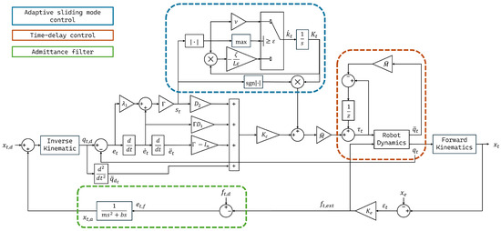
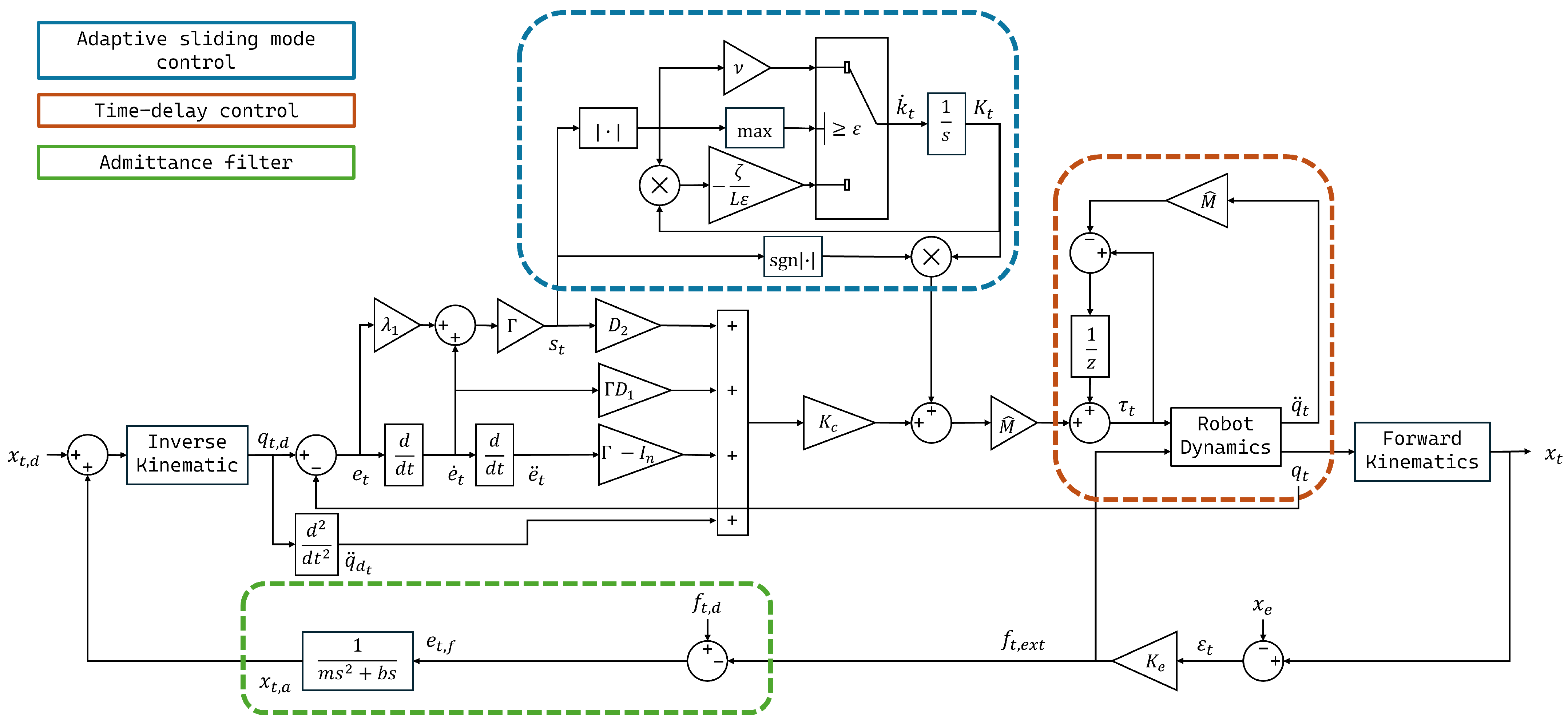
This study employs the robot controller based on the TDC and ASMC designed in Section 2.1 and Section 2.2. The controller is expanded by adding ASMC to compensate for the TDE error, which is a structural limitation of the TDC-based controllers used in previous force-tracking studies. The block diagram shown in Figure 1 illustrates the overall operating principle of the proposed framework. The desired trajectory is tracked by the inner TDC + ASMC controller in joint space, while the outer admittance loop converts the force-tracking error into a position compensation signal. This compensation is added to the desired trajectory and delivered to the inner controller so that force tracking and position tracking can be achieved within a unified control structure.
Figure 1.
Framework of the force/position tracking control.
2.1. Time-Delay Control
The dynamics of an n-joint robot manipulator is generally expressed as follows:
where , , and denote the joint position, velocity, and acceleration vectors, respectively. Furthermore, is the inertia matrix, is the Coriolis matrix, and is the gravity vector. represents the friction vector, and denotes the input torque vector.
In real-world applications, it is difficult to accurately design all model parameters, and controllers must handle uncertainties and disturbances. One widely used approach is TDC, which estimates the unmodeled dynamics using one-step-delayed joint acceleration and input torque.
First, the robot dynamics in (1) can be rewritten in an alternative form suitable for time-delay control as follows:
where is the control-gain matrix, composed of positive diagonal elements. For notational simplicity, the functional arguments of the dynamic terms are omitted in the following derivation, that is, , , , and , and is defined based on (1) as , which ensures that (2) is equivalent to (1). In TDC, is approximated using information from the previous time step as follows:
where L denotes the sampling period. Then, we can define the estimation error as follows:
This is called the TDE error, and for , becomes smaller and bounded.
In the ideal case where the TDE error satisfies , the control input torque () for tracking of the target-joint trajectory () is designed as follows:
where , , and and are both diagonal and positive definite matrices. By substituting (5) into (2), the error dynamics can be expressed as
Ideally, the stability of a second-order linear system can be ensured when , since and are diagonal matrices whose entries are strictly positive. However, in practice, is inevitably nonzero because of the finite sampling period of the digital controller.
Although TDC offers advantages in terms of simplicity and robustness, there is potential to improve its compensation for TDE errors. To this end, we adopt ASMC with the adaptive gain mechanism designed to reduce TDE-induced errors while retaining simplicity.
2.2. Adaptive Sliding Mode Control
In conventional sliding mode control, a sliding variable in the form of is usually considered. In this study, following the approach described in [17], the sliding variable is defined as follows:
where is a diagonal matrix satisfying and represents both diagonal and positive definite matrices. With the introduction of the terms, the sliding variable has an additional compensating effect beyond the simple error and error-derivative terms, providing stronger convergence characteristics, even under the same TDE error conditions.
The overall control input is designed by adding the TDC structure defined in (5) with an additional compensation term. Based on (5), the nominal control term () is defined as follows, following [17]:
where is both a diagonal and positive definite matrix, , and the gain matrices satisfy and . With as the applied control input in place of , the error dynamics are rewritten as follows:
that is, when the condition of is satisfied, the TDE error enters the error dynamics as rather than , so its effect is reduced compared with the original method (6). Therefore, not only adds the compensation term for sliding surface convergence but also reconstructs the error dynamics themselves to mitigate the influence of TDE error.
The final control input is defined by adding the compensation term to as follows:
where is an adaptively adjusted gain matrix. The added compensation term () drives toward the origin, enhancing robustness against uncertainties, and effectively suppresses TDE error, along with .
Following [22], we develop an adaptive law that preserves the basic structure while introducing a decline-rate reduction factor. The law is expressed as follows:
where is a tunable adaptive rate, is a positive scalar, and is a decline-rate reduction factor that modulates the contribution of the adaptive term, thereby affecting the convergence behavior and robustness of the controller. It should be noted that does not directly determine the steady-state tracking error but influences the transient response and disturbance rejection capability. During the increasing interval, the adaptive gain increases proportionally to the magnitude of , enabling robust tracking, even under high uncertainty. In contrast, during the decreasing interval, the adaptive gain decreases, reducing excessive gain near the sliding surface. This adaptive behavior also contributes to chattering reduction. Unlike conventional SMC with a fixed high switching gain, the proposed law decreases the adaptive gain inside the boundary layer, thereby avoiding unnecessarily aggressive switching near the sliding surface. Consequently, smoother control action can be achieved while preserving robustness against uncertainties and TDE errors.
In particular, when , the adaptive law in (11) becomes
which is a separable first-order differential equation. Dividing both sides by yields
Using the identity expressed as and integrating from (the time at which is first satisfied) to t, we obtain
This result shows that, inside the boundary layer, the adaptive gain follows an exponential-form evolution, where the decay rate is directly scaled by . Therefore, acts as a parameter that explicitly determines the exponential decay rate of the adaptive gain within the boundary layer.
Remark 1.
The proposed adaptive law introduces a decline-rate reduction factor (ζ) that explicitly controls the decay rate of the adaptive gain inside the boundary layer. From the exponential-form solution, it is evident that ζ directly scales the rate at which the adaptive gain decreases after the sliding variable enters the boundary layer. In particular, smaller values of ζ lead to slower decay of the adaptive gain, thereby preserving the compensation capability against disturbances and TDE errors for a longer duration. Moreover, when , the proposed adaptive law reduces to the conventional method described in [22], indicating that the proposed formulation provides a generalized extension of the existing approach.
Assumption 1.
The TDE error () is bounded and satisfies .
Theorem 1.
For diagonal matrices (, , ), a sampling period (L), and scalars (, , ), if the robot manipulator is controlled by the proposed control input (10), together with the adaptive law (11), then there exists a finite time () such that for all , and the sliding variable is uniformly ultimately bounded (UUB) with the following explicit bound:
where .
Proof.
First, we define the Lyapunov function candidate as follows:
where is an arbitrary positive constant and is positive with respect to both and . Next, the time derivative of is given by
The time derivative of the sliding variable (7) is expressed as follows:
Using the relationships expressed as and , (19) can be rewritten as follows:
Here, since , the second term of (22) is less than or equal to zero. Furthermore, holds, meaning that the magnitude of the disturbance term is bounded by the finite constant ().
Now, we explicitly substitute the adaptive law to evaluate the sign of . To balance the disturbance bound, we choose .
- (i)
- Outside the boundary layer, .
In this region, the adaptive law is given by . Therefore, the last term of (22) can be expressed as follows:
Substituting this result into the expression for in (22), we can obtain
- (ii)
- Inside the boundary layer, .
In this region, the adaptive law is given by ; thus, the negativeness of cannot be guaranteed. Therefore, inside the boundary layer, we derive an upper bound on the sliding variable using the concept of uniform ultimate boundedness (UUB) First, when , it follows from (24) that . Hence, decreases monotonically, and enters the region of within a finite time (). When , the ultimate bound of is obtained using only the upper and lower bounds of the Lyapunov function. From the previously defined (16),
In addition, since decreases in the outer region and the trajectory eventually reaches the boundary (), the following relationship always holds inside the boundary layer:
Since within the boundary layer, remains bounded, and we can define
which leads to
According to this inequality, the sliding variable in (7) is UUB for . The proof is complete. □
3. Force Tracking Control Method
Since the robot manipulator considered in this study operates based on position inputs, an admittance filter can be applied in the outer loop to enable desired force tracking. Admittance control interprets the concept of impedance control in reverse, converting the force error into a position compensation signal. It offers the advantage of being easily applicable to position controllers.
First, the force error between the desired force () and the external contact force () is defined as follows:
where , where represents the virtual position response corresponding to the force error. These are defined for the simulation experiments, and and represent the stiffness and position of the virtual contact environment, respectively. The admittance filter models this force error as the response of a mass–spring–damper system, which can be expressed as
where m, b, and k denote the virtual inertia, damping, and stiffness coefficients. Applying the Laplace transform, the transfer function of the admittance filter is given by
where denotes the position compensation generated by the force error and is the Laplace transform of the force error. As pointed out in [10], when , a steady-state force-tracking offset may occur. Therefore, a simplified form of the admittance filter with is adopted as follows:
The final target trajectory is defined as:
that is, by adding the generated by the admittance filter to the , the robot is guided to follow the desired force during interaction with the external environment.
To clarify the stability of the outer admittance loop, the force-error dynamics in (30) and the linear contact relation () are combined with (31) when :
Then,
Applying the Laplace transform yields the following:
Therefore, the transfer function is defined as follows:
For a constant desired force input, the final value theorem gives
This result shows that, under a constant desired force input, the position error relative to the environment converges to a finite steady-state value. Therefore, the error signal governing the outer admittance loop remains bounded and does not diverge through the feedback process. This shows that the admittance filter provides a stable reference modification in the force-feedback loop.
This study adopted the admittance-filter structure for force tracking described above. This is the same approach proposed in [10], a proven method for providing force-tracking capabilities to position-based control robots.
4. Results
4.1. Simulation Setup
Simulation experiments were performed to evaluate the desired position and force-tracking performance of the robotic arm’s end effector. The experimental environment was implemented using MATLAB R2024b, Simulink 24.2 and Robotics System Toolbox 24.2. The simulation was implemented over the interval of – using a fixed step size of , which was consistently used for the TDC update and the adaptive-law update.
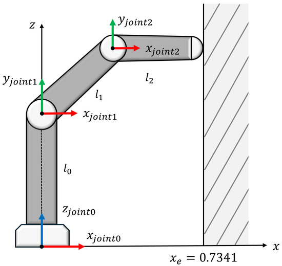
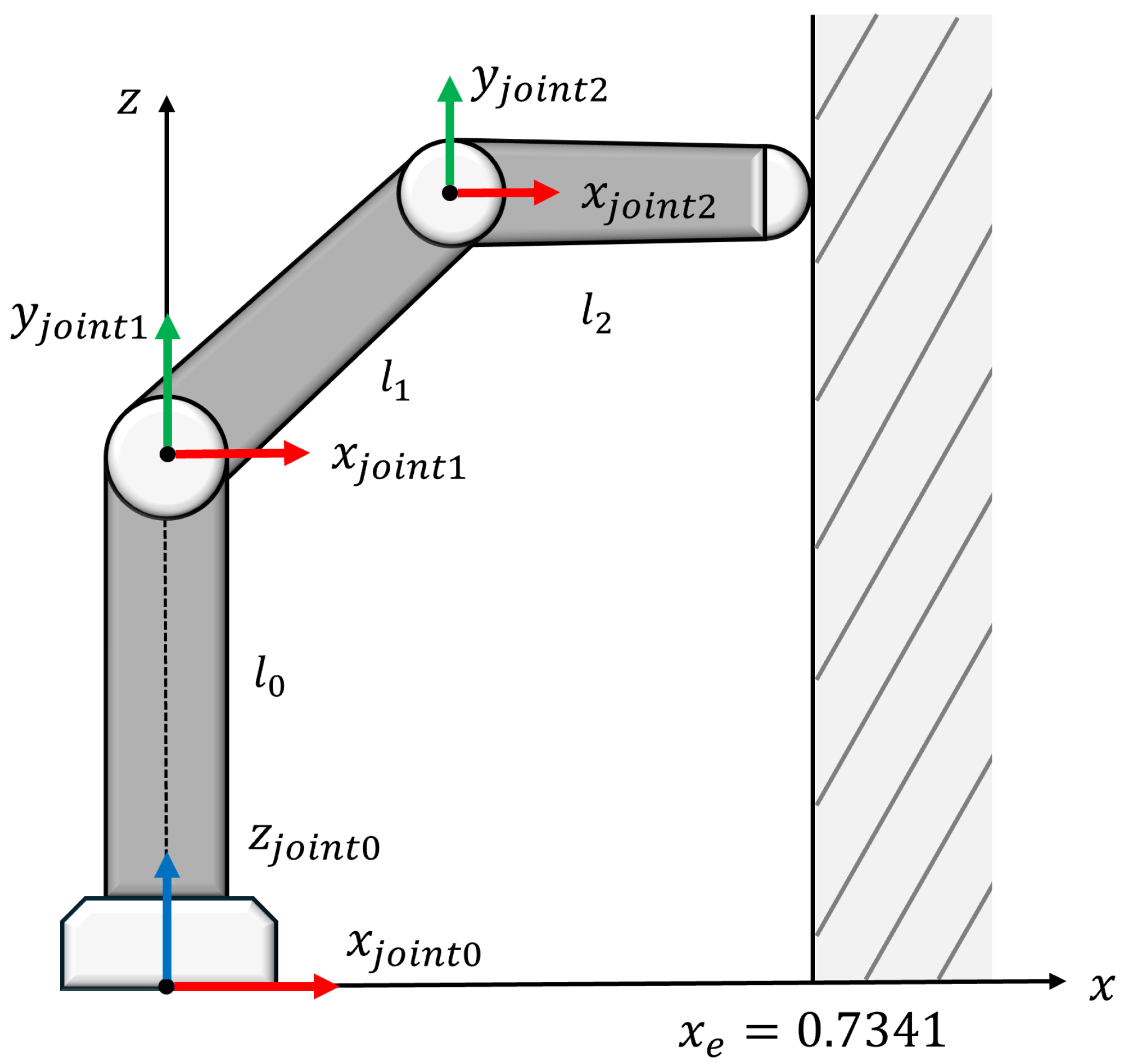
The simulation environment used in this study is shown in Figure 2, and the model of the robotic arm follows a three-link structure. Link 0 connected to joint 0 has a mass of 30 kg and a length of m. Link 1 connected to joint 1 has a mass of kg and a length of m, and Link 2 connected to joint 2 has a mass of kg and a length of m. For all joints, the friction force is modeled as . The initial joint angles of the robot arm are set to , with the end-effector in contact with a virtual wall located at . The desired position is defined to follow a sine trajectory along the z-axis, while the desired force is set to apply a constant 10 N along the x-axis. Through this setup, the robot simultaneously tracks both the desired trajectory and the desired force within the -plane.
Figure 2.
Simulation setup of the robot arm and virtual contact environment.
To validate the effectiveness of the proposed method, comparative simulations were performed using the tracking control schemes described in [10,18,22] and the proposed method under the same robot model, reference trajectory, virtual contact environment, and admittance-filter parameters. The parameters of the admittance filter in (33) were set to , , and . The controller structure of each method was implemented according to the corresponding reference, while the control gains were individually tuned under the common simulation environment to achieve the best tracking performance. In particular, the method described in [22] was treated as the special case of the proposed framework with , whereas the proposed method additionally investigates the effect of the decline-rate reduction factor by varying .
4.2. Simulation Results
4.2.1. Comparison with Existing Methods
For the compared controllers, the TDC baseline proposed in [10] was implemented as follows:
where , , , and were used.
The TDC + ASMC scheme proposed in [18] was implemented as follows:
where , , , and the parameters related to the adaptive gain () were tuned under the common simulation environment to achieve the best tracking performance. In addition, considering the role of used in the other compared controllers, was set to instead of .
The TDC + ASMC scheme proposed in [22] and the proposed method were implemented using the same controller structure as follows with (10):
where , , , , and were used. For the adaptive law in (11), the parameters were set to , , and . Here, the method in [22] corresponds to the special case with , whereas the proposed method uses the same control structure with . For clarity, the controller parameters used in the comparative simulations are summarized in Table 1.
Table 1.
Summary of controller parameters used in the comparative simulations.
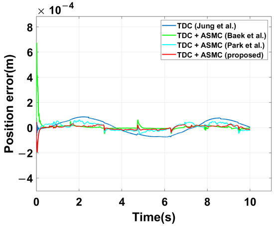
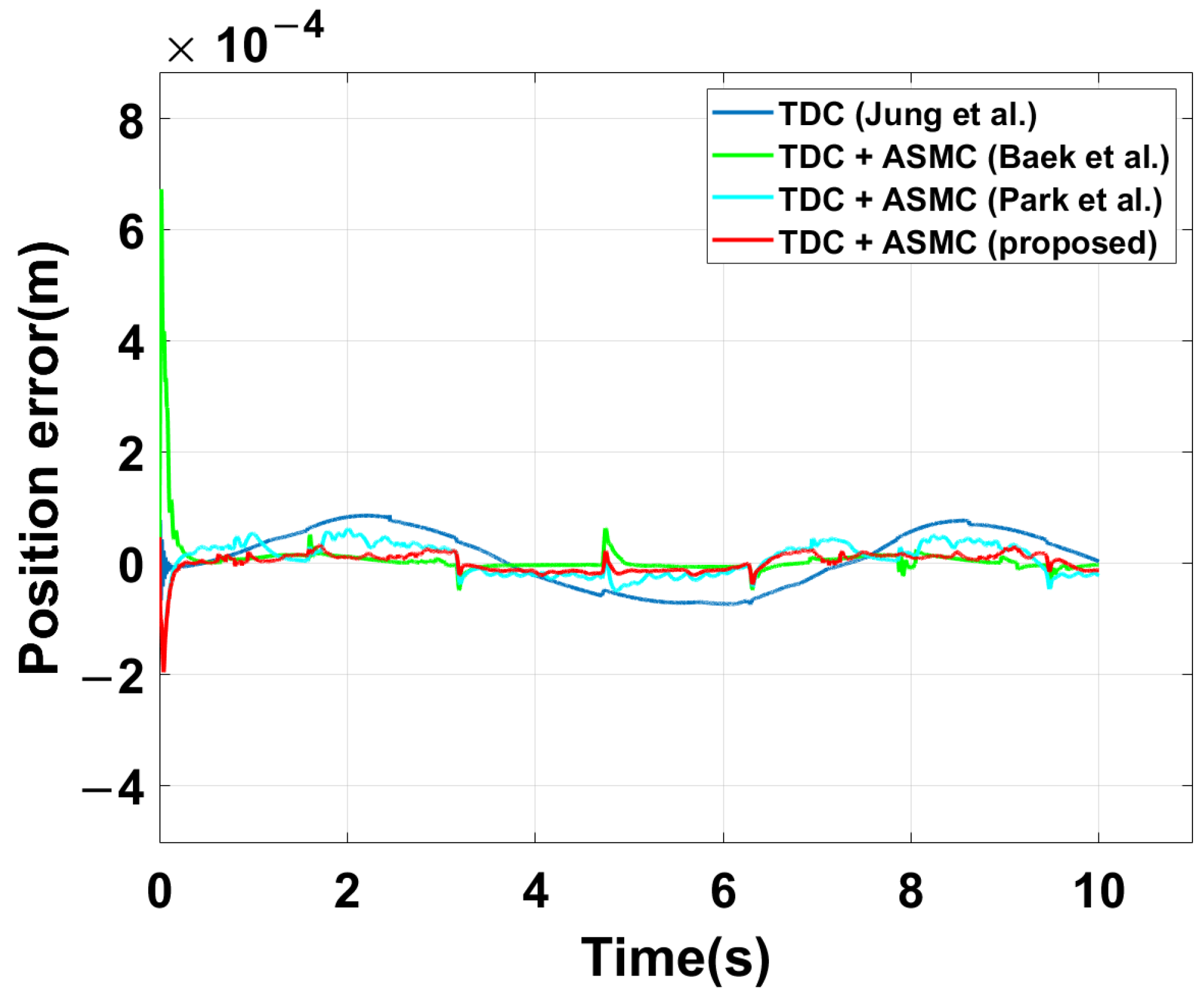
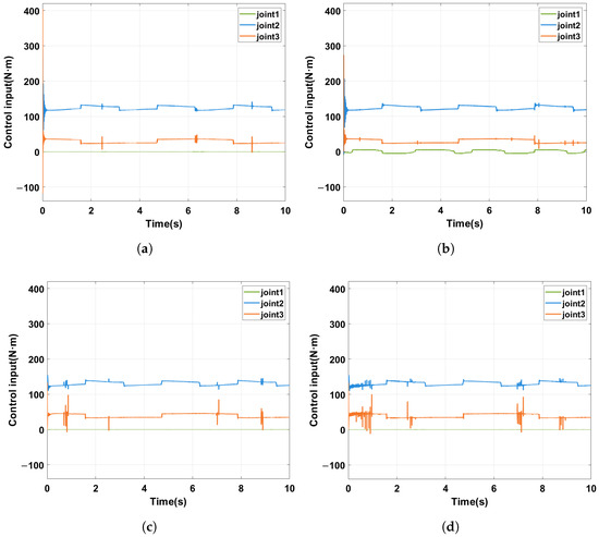
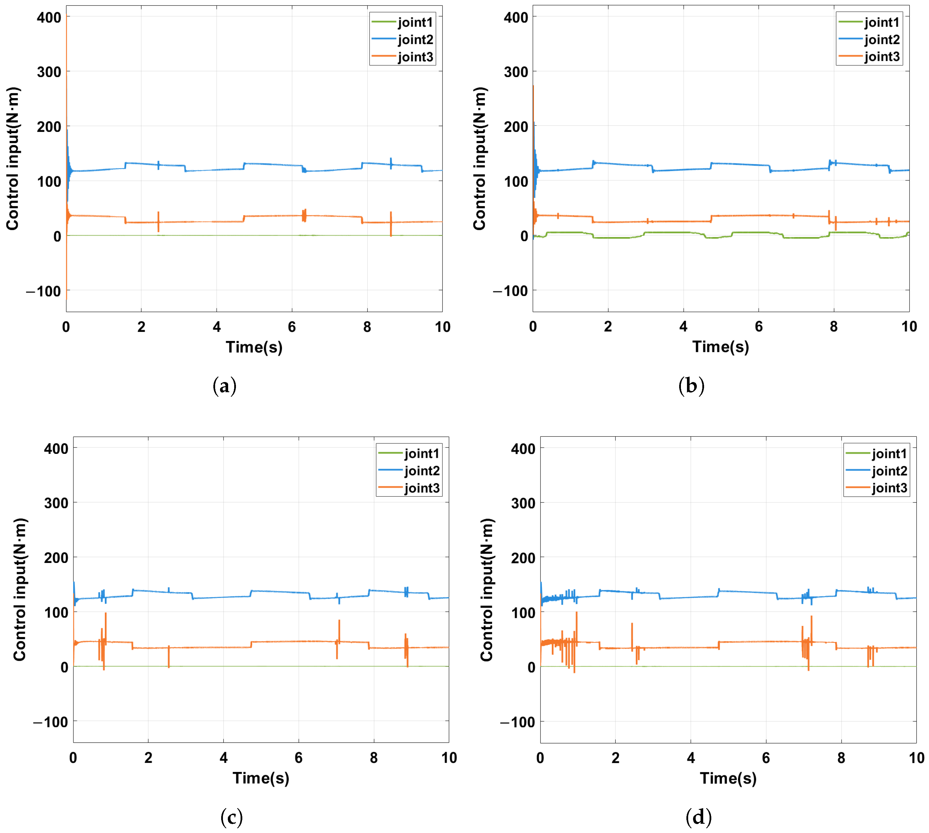
Figure 3 shows the z-axis position-tracking error of the end effector for the compared methods. Since the desired trajectory varies sinusoidally along the z-axis, the z-axis error provides a direct measure of the tracking performance. It can be observed that the baseline TDC method proposed in [10] exhibits the largest tracking deviation, while the existing ASMC-based methods reduce the tracking error compared with the baseline. In particular, over the entire simulation interval from 0 to 10 s, the TDC-based controller proposed in [10] achieved an RMSE of 0.0522 mm, whereas the TDC + ASMC methods proposed in [18,22] reduced the RMSE to 0.0417 mm and 0.0313 mm, respectively. Among the compared methods, the proposed method yields the smallest position-tracking error overall, achieving the lowest RMSE of 0.019 mm. In addition, the control input responses in Figure 4 show that all methods maintain bounded torque profiles, while the ASMC-based methods exhibit slightly more active corrective variations than the baseline TDC. This result suggests that the improved tracking performance of the proposed method is achieved not by excessive control effort but by a more effective compensation of TDE errors and uncertainties.
Figure 3.
Comparison of the z-axis position-tracking error for existing methods [10,18,22] and the proposed method.
Figure 4.
Comparison of the control input trajectories for the compared methods. (a) TDC proposed in [10]. (b) TDC + ASMC proposed in [18]. (c) TDC + ASMC proposed in [22]. (d) Proposed method.
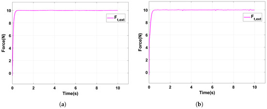
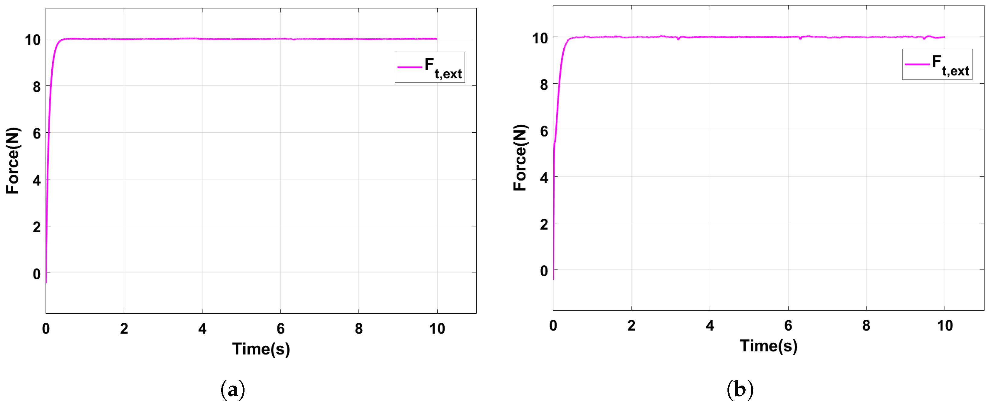
To verify that the improvement in position tracking does not degrade force-tracking performance, Figure 5 compares the exerted force responses of the TDC-based baseline and the proposed method under the same admittance-filter parameters. Although the internal tracking controller is changed, accurate force tracking is maintained in both cases. This result indicates that the proposed method enhances position-tracking performance while preserving the force-tracking capability provided by the admittance filter.
Figure 5.
Comparison of the exerted force responses under the same admittance-filter parameters. (a) TDC-based baseline. (b) Proposed method.
The TDC-based controller proposed in [10] has a simple structure and can be effectively integrated with the admittance filter for force tracking. However, because it relies on time-delayed approximation, its position-tracking performance is more directly affected by residual TDE errors. The TDC + ASMC controller proposed in [18] reduces this effect by introducing an adaptive switching compensation term, thereby improving the tracking accuracy compared with the TDC baseline. The controller proposed in [22] further enhances the tracking performance by employing an improved ASMC structure and corresponds to the special case of the proposed framework when . In contrast, the proposed method introduces the decline-rate reduction factor () to explicitly regulate the decay behavior of the adaptive gain inside the boundary layer. By slowing the decay of the adaptive gain, the proposed method retains compensation capability against residual TDE errors and uncertainties for a longer duration. As a result, it achieves the lowest position-tracking RMSE among the compared methods while maintaining bounded control input trajectories and preserving the force-tracking capability provided by the admittance filter.
4.2.2. Effect of the Decline-Rate Reduction Factor ()
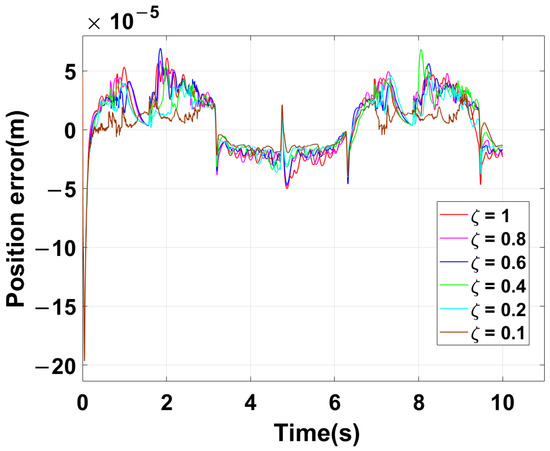
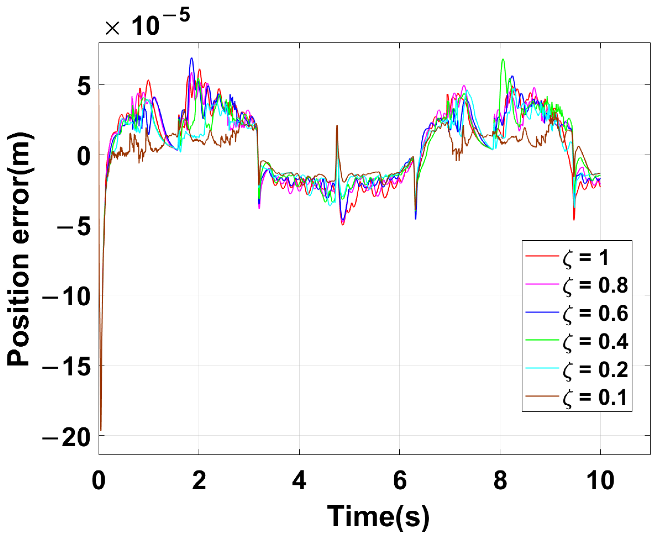
This subsection focuses on the effect of the decline-rate reduction factor () within the proposed framework. Figure 6 shows the z-axis position-tracking error of the end effector for different values of . As decreases, the tracking error generally tends to decrease because the adaptive gain does not decay excessively inside the boundary layer, thereby preserving the compensation capability against TDE errors for a longer duration. The RMSE decreases as is reduced from 1 to 0.4, whereas the same RMSE value is observed at and . Among the tested cases, the best tracking performance is obtained at .
Figure 6.
Position error along the z-axis for different values of .
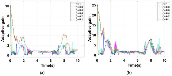
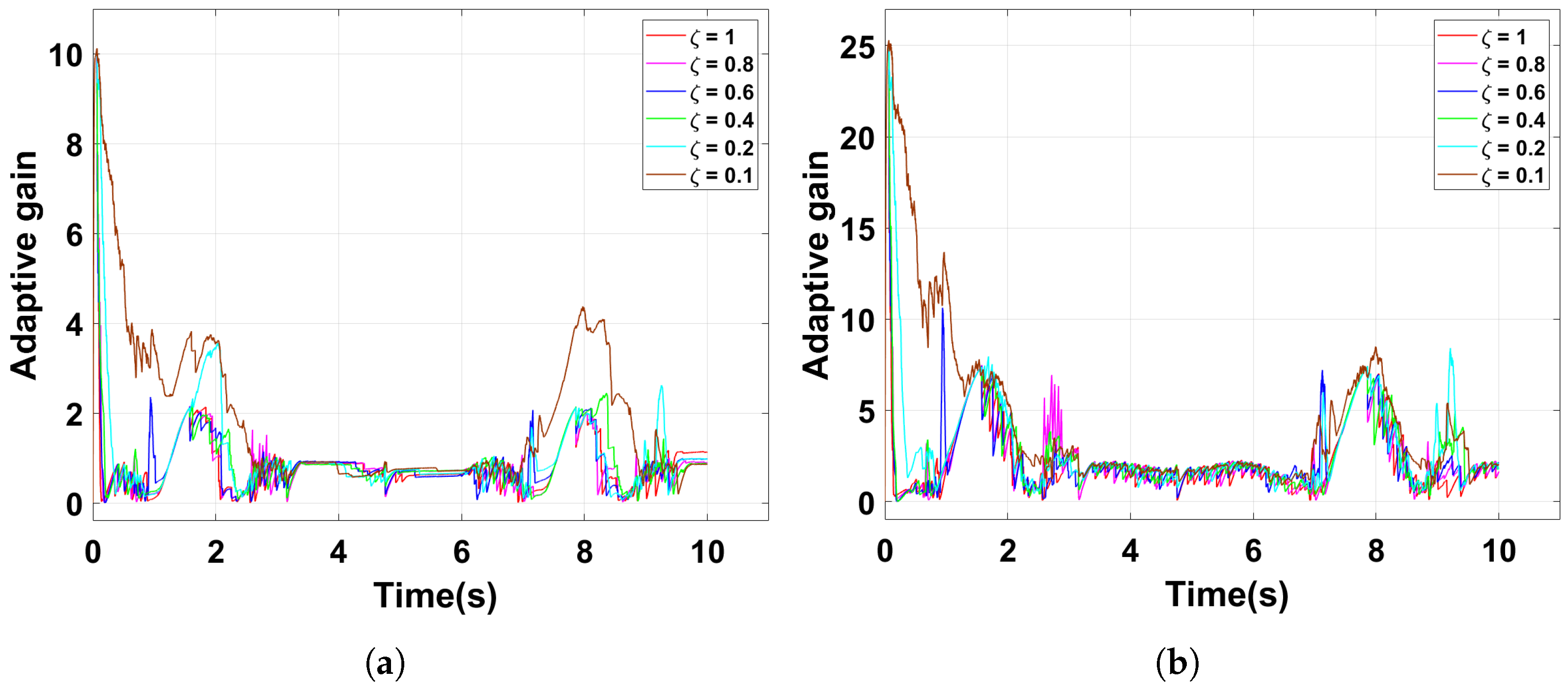
Figure 7 further compares the adaptive gain trajectories of Joint 2 and Joint 3 for different values of . As decreases from 1 to 0.1, the adaptive gains in both joints decrease more gradually after entering the boundary layer. This indicates that a smaller slows the decay of the adaptive gain, allowing the compensation capability against TDE errors to be retained for a longer duration.
Figure 7.
Adaptive gain () trajectories for different values of . (a) Joint 2. (b) Joint 3.
For a comprehensive quantitative comparison, Table 2 summarizes the RMSE values of the z-axis position -tracking error for all compared methods, together with the tested values of . As was decreased within the proposed framework, the RMSE decreased to 0.0299 mm, 0.0293 mm, 0.0280 mm, 0.0280 mm, and 0.0190 mm for , , , , and , respectively. These results confirm that reducing within the proposed framework improves the position-tracking performance beyond that of existing TDC- and ASMC-based methods.
Table 2.
RMSE of the end-effector position along the z-axis.
5. Discussion and Conclusions
This paper presented a force/position tracking framework for collaborative robots by combining an admittance-based outer loop with a TDC + ASMC-based inner controller. The main contribution of the proposed method lies in introducing the decline-rate reduction factor () into the adaptive law, which explicitly regulates the decrease rate of the adaptive gain after the sliding variable enters the boundary layer. Unlike the conventional TDC-based controller, which inherently suffers from residual TDE errors, and unlike prior TDC + ASMC methods that do not explicitly regulate the gain decay rate, the proposed method can preserve the compensation capability against TDE errors and external disturbances for a longer duration. The simulation results support this interpretation. The proposed controller reduced the position RMSE from mm for the TDC baseline to mm while maintaining the force-tracking performance achieved through the same admittance filter. Moreover, as was reduced from 1 to 0.1, the adaptive gain decayed more gradually, and the position-tracking performance improved accordingly. These results indicate that the explicit regulation of adaptive-gain decay inside the boundary layer is an effective way to enhance position-tracking performance without sacrificing the force-tracking capability of the admittance-based framework. Overall, these results show that the proposed introduction of the decline-rate reduction factor () provides a meaningful extension of existing TDC + ASMC-based force/position tracking methods.
However, the present validation is limited to simulation-based results, and additional challenges may arise in real-time implementation. In practical collaborative robot systems, the performance of the proposed controller can be influenced by increased TDE errors due to the sampling period and computation delay, as well as by sensor noise in the force measurement process. From a computational perspective, the proposed controller is expected to be feasible for real-time implementation because it is built on the simple TDC framework and mainly requires algebraic calculations of the sliding variable, adaptive gain update, and admittance-based compensation using diagonal gain matrices, without iterative optimization or learning-based inference during online control. Nevertheless, its practical computational cost should be further verified on an actual robot platform under the target control period and hardware conditions. Therefore, although the simulation results support the potential effectiveness of the proposed approach, further investigation is necessary to verify its practical applicability under real-world operating conditions. Future work will include a more comprehensive robustness assessment by incorporating robot model uncertainties and external disturbances into the simulation framework. In addition, experimental validation using an actual collaborative robot will be carried out to further examine the effectiveness of the proposed approach in practical environments.
Author Contributions
Conceptualization, S.O. and N.K.K.; methodology, S.O. and S.Y.L.; software, S.O., S.Y.L. and N.K.K.; validation, S.O. and S.Y.L.; formal analysis, S.O. and N.K.K.; investigation, S.O.; resources, N.K.K.; data curation, B.C.; writing—original draft preparation, S.O.; writing—review and editing, S.Y.L. and N.K.K.; visualization, B.C.; supervision, S.Y.L. and N.K.K.; project administration, S.O. and N.K.K.; funding acquisition, S.Y.L. All authors have read and agreed to the published version of the manuscript.
Funding
This paper was supported by a Korea Institute for Advancement of Technology(KIAT) grant funded by the Korea Government(MOTIE) (RS-2026-25530975, HRD Program for Industrial Innovation) and the 2026 Yeungnam University Research Grant.
Data Availability Statement
The original contributions presented in this study are included in the article. Further inquiries can be directed to the corresponding authors.
Acknowledgments
The authors express their sincere appreciation to all those who contributed to this study.
Conflicts of Interest
The authors declare no conflicts of interest.
References
- Farajtabar, M.; Charbonneau, M. The path towards contact-based physical human–robot interaction. Robot. Auton. Syst. 2024, 182, 104829. [Google Scholar]
- Ajoudani, A.; Zanchettin, A.M.; Ivaldi, S.; Albu-Schäffer, A.; Kosuge, K.; Khatib, O. Progress and prospects of the human–robot collaboration. Auton. Robot. 2018, 42, 957–975. [Google Scholar]
- Suomalainen, M.; Karayiannidis, Y.; Kyrki, V. A survey of robot manipulation in contact. Robot. Auton. Syst. 2022, 156, 104224. [Google Scholar] [CrossRef] [Scilit]
- Baspinar, C. On robust position/force control of robot manipulators with constraint uncertainties. IFAC Proc. Vol. 2012, 45, 555–560. [Google Scholar] [CrossRef] [Scilit]
- Jung, S. Sliding mode control for a hybrid force control scheme of a robot manipulator under uncertain dynamics. Int. J. Control. Autom. Syst. 2023, 21, 1634–1643. [Google Scholar] [CrossRef] [Scilit]
- Baspinar, C. Robust position/force control of constrained flexible joint robots with constraint uncertainties. J. Intell. Robot. Syst. 2020, 100, 945–954. [Google Scholar] [CrossRef] [Scilit]
- Keemink, A.Q.; Van der Kooij, H.; Stienen, A.H. Admittance control for physical human–robot interaction. Int. J. Robot. Res. 2018, 37, 1421–1444. [Google Scholar] [CrossRef] [Scilit]
- Caccavale, F.; Siciliano, B.; Villani, L. Robot impedance control with nondiagonal stiffness. IEEE Trans. Autom. Control 2002, 44, 1943–1946. [Google Scholar]
- Ott, C.; Nakamura, Y. Admittance Control using a Base Force/Torque Sensor. IFAC Proc. Vol. 2009, 42, 467–472. [Google Scholar] [CrossRef] [Scilit]
- Jung, S.; Jeong, D.J. Admittance force tracking control schemes for robot manipulators under uncertain environment and dynamics. Int. J. Control. Autom. Syst. 2021, 19, 3753–3763. [Google Scholar] [CrossRef] [Scilit]
- Zhang, D.; Wei, B. A review on model reference adaptive control of robotic manipulators. Annu. Rev. Control 2017, 43, 188–198. [Google Scholar] [CrossRef] [Scilit]
- Adhikary, N.; Mahanta, C. Sliding mode control of position commanded robot manipulators. Control Eng. Pract. 2018, 81, 183–198. [Google Scholar] [CrossRef] [Scilit]
- Baek, J.; Cho, S.; Han, S. Practical time-delay control with adaptive gains for trajectory tracking of robot manipulators. IEEE Trans. Ind. Electron. 2017, 65, 5682–5692. [Google Scholar] [CrossRef] [Scilit]
- Sun, Y.; Liang, X.; Wan, Y. Tracking control of robot manipulator with friction compensation using time-delay control and an adaptive fuzzy logic system. Actuators 2023, 12, 184. [Google Scholar] [CrossRef] [Scilit]
- Yu, L.; Huang, J.; Luo, W.; Chang, S.; Sun, H.; Tian, H. Sliding-mode control for PMLSM position control—A review. Actuators 2023, 12, 31. [Google Scholar]
- Zeinali, M.; Notash, L. Adaptive sliding mode control with uncertainty estimator for robot manipulators. Mech. Mach. Theory 2010, 45, 80–90. [Google Scholar] [CrossRef] [Scilit]
- An, H.M.; Lee, J.W.; Seo, D.H.; Lee, S.Y. An Adaptive Sliding Mode Control with Novel Sliding Variable-Based Adaptive Law for Disturbed Robot Manipulators. IEEE Access 2024, 12, 165227–165235. [Google Scholar] [CrossRef] [Scilit]
- Baek, J.; Jin, M.; Han, S. A new adaptive sliding-mode control scheme for application to robot manipulators. IEEE Trans. Ind. Electron. 2016, 63, 3628–3637. [Google Scholar] [CrossRef] [Scilit]
- Fateh, A.; Momeni, H. Time delay control of a robotic manipulator using an enhanced adaptive sliding mode control switching gain. Int. J. Dyn. Control 2025, 13, 91. [Google Scholar] [CrossRef] [Scilit]
- Boudjedir, C.E.; Bouri, M.; Boukhetala, D. An enhanced adaptive time delay control-based integral sliding mode for trajectory tracking of robot manipulators. IEEE Trans. Control Syst. Technol. 2022, 31, 1042–1050. [Google Scholar] [CrossRef] [Scilit]
- Zhang, Z.; Li, X.; Wang, X.; Zhou, X.; An, J.; Li, Y. TDE-based adaptive integral sliding mode control of space manipulator for space-debris active removal. Aerospace 2022, 9, 105. [Google Scholar]
- Park, J.; Kwon, W.; Park, P. An improved adaptive sliding mode control based on time-delay control for robot manipulators. IEEE Trans. Ind. Electron. 2022, 70, 10363–10373. [Google Scholar] [CrossRef] [Scilit]

Disclaimer/Publisher’s Note: The statements, opinions and data contained in all publications are solely those of the individual author(s) and contributor(s) and not of MDPI and/or the editor(s). MDPI and/or the editor(s) disclaim responsibility for any injury to people or property resulting from any ideas, methods, instructions or products referred to in the content. |
© 2026 by the authors. Licensee MDPI, Basel, Switzerland. This article is an open access article distributed under the terms and conditions of the Creative Commons Attribution (CC BY) license.