


Abstract
Cracks and defects are inevitable during the long-term use of structures. This study focuses on determining the stress intensity factors of multi-cracked structures by using a new fast multipole dual boundary element method. Numerical examples show that the results of the present method agree well with analytic solutions. When the crack distribution changes, the most unfavorable conditions also change. The shape of the defect has an effect on the stress intensity factors of nearby cracks. Among triangular, rectangular, hexagonal, and circular defects, when the area of the defect is identical, the triangular pore is more likely to induce crack propagation, while the circular pore is more secure. The above results can be used as a reference for structural design and optimization.
Keywords:
fast multipole dual boundary element method; stress intensity factor; multiple cracks; defects MSC:
65M38
1. Introduction
Fracture analysis is crucial for assessing the safety and remaining life of structures [1,2,3]. The assessment parameters include stress intensity factor (SIF), J-integral, and strain energy release rate, among others. Notably, the SIF has emerged as a prevalent parameter due to its broad applicability.
Various methods are available for analyzing fracture problems, such as experimental measurements, analytical solutions, and numerical techniques. Experimental measurements [4,5,6,7,8] can obtain accurate and effective results but are time-consuming. Analytical formulas [9] are highly efficient and accurate but are suitable for some simple cases. Numerical techniques have the advantage of wide applicability; the most commonly used include but are not limited to, the meshless method [10], the finite element method (FEM) [11,12,13,14,15], and the boundary element method (BEM) [16,17,18]. These numerical techniques need to combine with some special treatments to obtain the SIF, such as the J-integral [19,20], the M-integral [21], the interaction integration [22], and the displacement and stress extrapolation methods [23]. The J-integral is path-independent, i.e., the computing results do not depend on the choice of integration path. The M-integral is also path-independent and has a definite relation to the J-integral. Compared with the J integral, the M-integral applies to a wider range but involves more complicated calculations. The interaction integration obtains the SIFs by establishing the auxiliary stress and displacement fields and can be used to calculate the SIFs in mixed mode. These integration methods all have high accuracy but are much more complicated than the displacement and stress extrapolation methods. The displacement extrapolation method has the advantages of wide applicability and simple implementation, making it especially suitable for multi-crack problems. Its accuracy can be further improved, which is one of the efforts of the present study.
In this study, a new fast multiple dual boundary element method (FMDBEM) combined with the displacement extrapolation method is developed to determine the SIFs of multi-cracked structures. Firstly, a novel variable-order asymptotic element (VAE) has been introduced to achieve highly accurate singular stress fields in the vicinity of the crack tip. Secondly, the crack-tip opening displacement (CTOD) and the least squares method are used to calculate the SIFs. Finally, the effects of defects on structural strength and the relationships between the SIF and the number of cracks are discussed.
2. Displacement Interpolation Method for SIFs
Considering a 2D cracked structure, the SIFs can be expressed as:
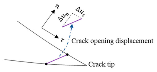
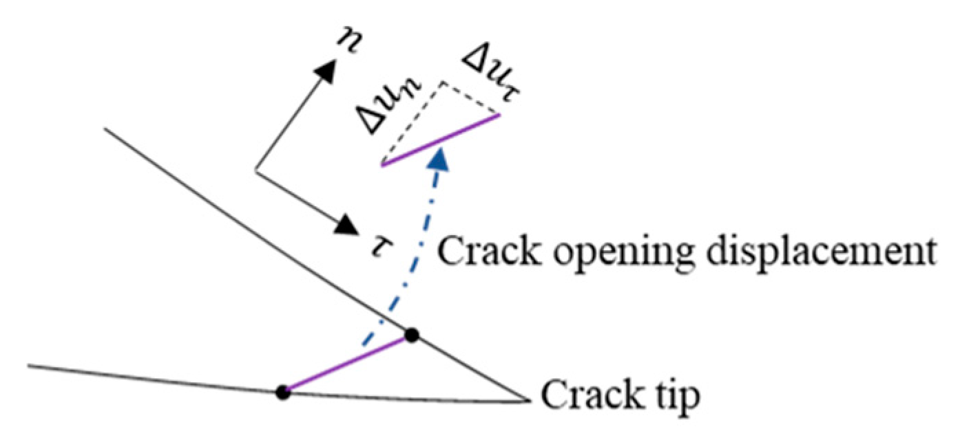
where for plane strain, for plane stress, are the displacement variation between the two crack surfaces along and n respectively, as seen in Figure 1.
Figure 1.
Crack-tip opening displacement.
To accurately obtain the SIFs, a set of data for () and () are first collected, as follows:
where and are the displacement along n and on the sample points, respectively. Then, the least squares method is used to fit , , as follows:
where N is the total number of sample points.
3. Determining Displacement and Stress Fields of Multi-Cracked Structures
For 2D cracked problems, the dual boundary integral equations are applied to the two surfaces of the cracks. The conventional boundary integral equation (CBIE) for displacements and the hyper-singular boundary integral equation (HBIE) [24] for tractions are written as follows:
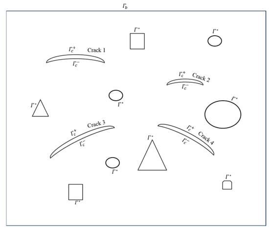
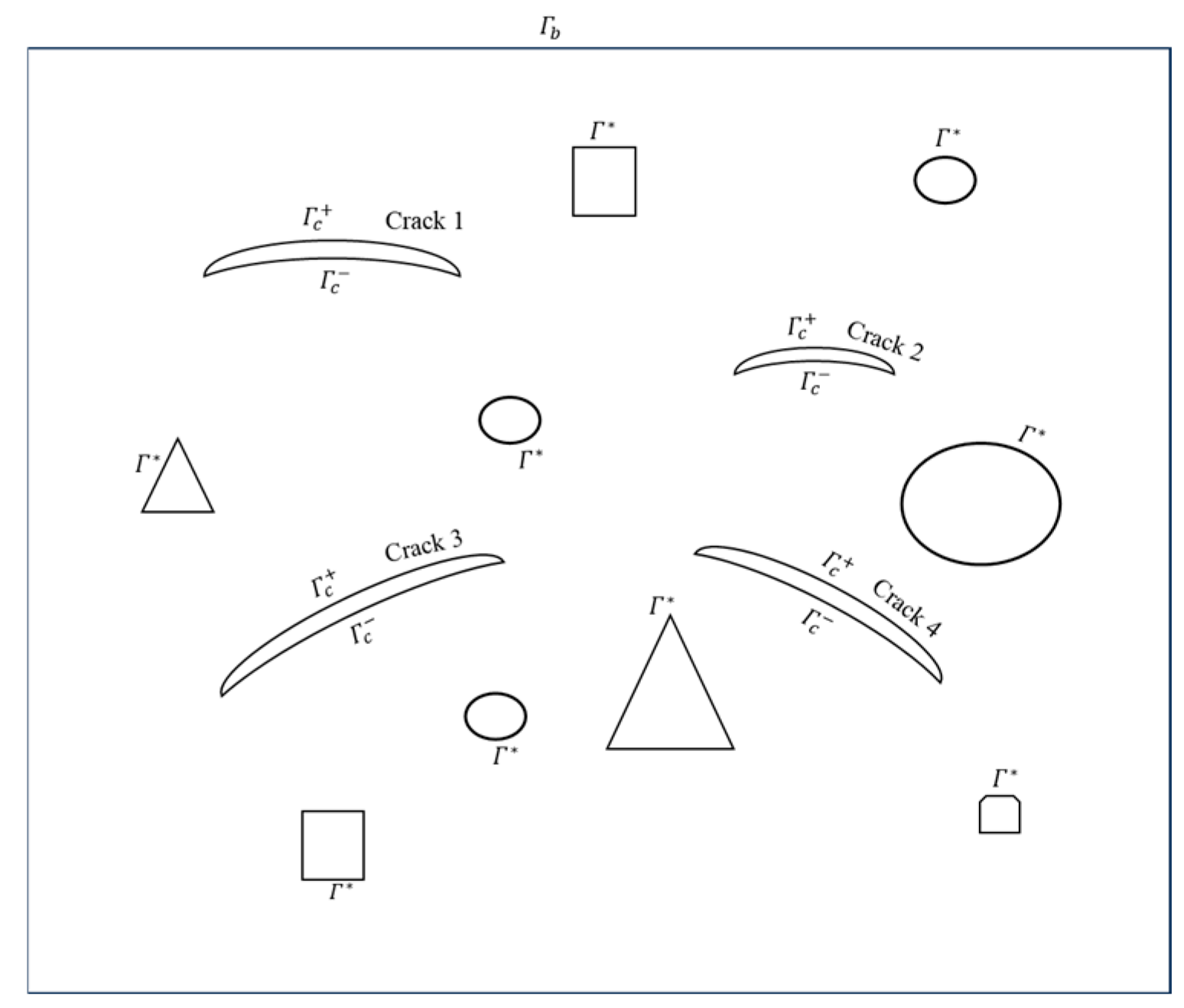
where is the source point, is the field point, and are the traction and displacement at , respectively, and is a coefficient. , , and are the fundamental solutions. CBIE is applied to the boundary and CBIE + HBIE = 0 is applied to the boundary , where is a coupling coefficient, as seen in Figure 2.
Figure 2.
The multi-cracked structure.
To simplify the expressions of the fundamental solutions, complex notation is used. The integrals on a typical boundary element in Equations (7) and (8) can be expressed as follows:
where , , , , indicates the complex conjugate.
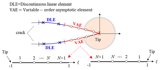
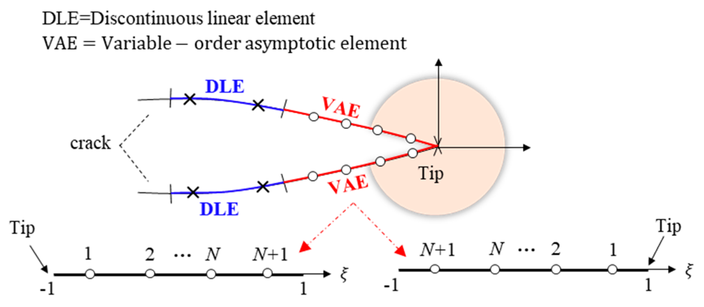
The conventional elements are difficult to accurately describe with regard to the singular stresses near the V-notch or crack tip region for the existence of singularity. Therefore, a novel VAE has been developed to capture the high gradient variation of singular stress fields around the V-notch or crack tip region, and discontinuous linear elements (DLEs) are arranged on all other boundaries, as shown in Figure 3.
Figure 3.
A novel variable-order asymptotic element.
The displacements and tractions on the VAE are assumed as follows:
where and are the stress and displacement exponents [25], respectively, and and are the traction and displacement coefficients, respectively. If the V-notch/crack tip is at = −1.0, = 1.0. If the V-notch/crack tip is at = 1.0, = −1.0. and are the traction and displacement at the other end of the VAE away from the tip, respectively. This feature allows the VAE to be directly connected to conventional elements without any connective elements. The new VAE can be suited for arbitrary angles with corresponding and .
In the fast multipole boundary element method for 2-D elastic problems, the boundary integrals are grouped into two categories through a quadtree structure: the far-field integrals on the elements that are far from the source point and the near-field integrals on the elements that are close to the source point. For the former, the fast multipole expansions are used for rapid evaluation. For the latter, direct evaluations are employed in the conventional boundary element method. More details can be found in refs. [26,27].
4. Numerical Results
4.1. A Rectangular Plate with an Internal Kinked Crack
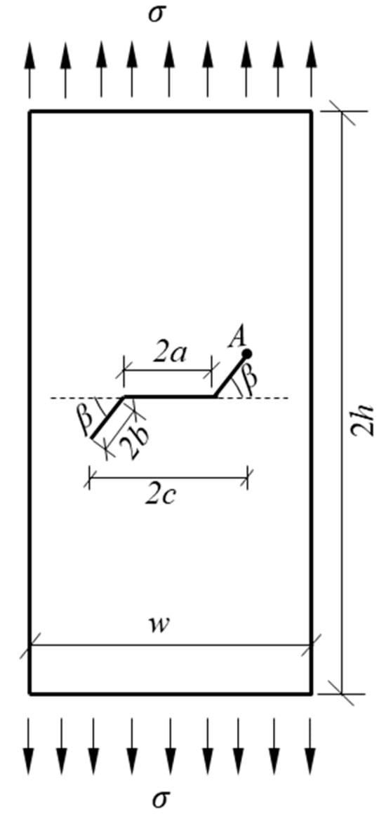
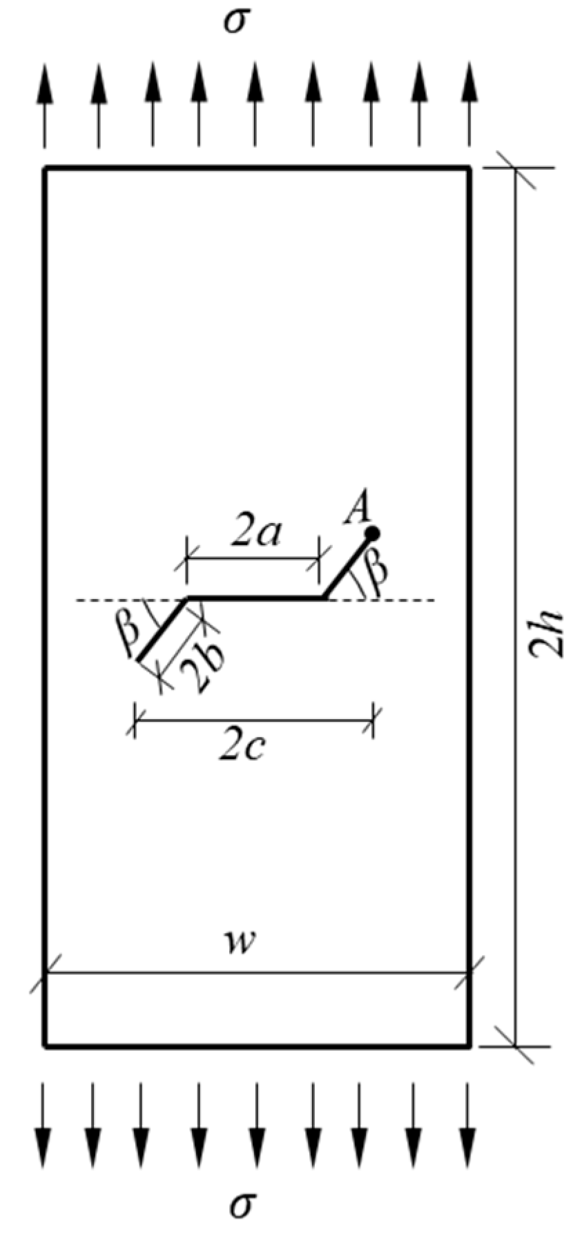
A rectangular plate with an internal kinked crack under tension is considered, as illustrated in Figure 4. The slant angle of the crack is β and the length is 2c. The plate has a width of w, a height of 2h, , E = 21, and Poisson’s ratio ν = 0.35.
Figure 4.
A rectangular plate with an internal kinked crack.
For the convenience of discussion, the normalized stress intensity factors , , and error are defined as follows:
The FMDBEM-VAE denotes that the VAE is used at the crack tip, while the FMDBEM-DLE denotes that the conventional discontinuous linear element (DLE) is used at the crack tip. The normalized stress intensity factors and obtained by the FMDBEM-VAE and FMDBEM-DLE are listed in Table 1 and Table 2, respectively. The total number of elements used by both the FMDBEM-VAE and FMDBEM-DLE are 66.
Table 1.
Normalized stress intensity factors .
Table 2.
Normalized stress intensity factors .
From Table 1 and Table 2, it can be observed that FI and FII obtained by the FMDBEM-VAE are in good agreement with the analytical solutions. In contrast, there is a notable discrepancy between the analytical solution and the results obtained by the FMDBEM-DLE. The conventional DLE struggles to capture the high gradient variation of the singular stress fields, while the VAE are capable of precisely describing the singularity.
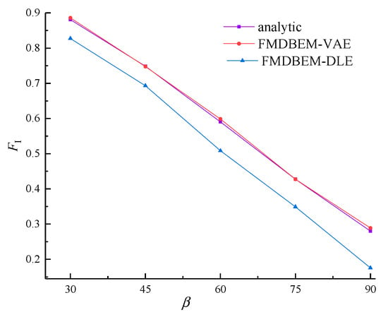
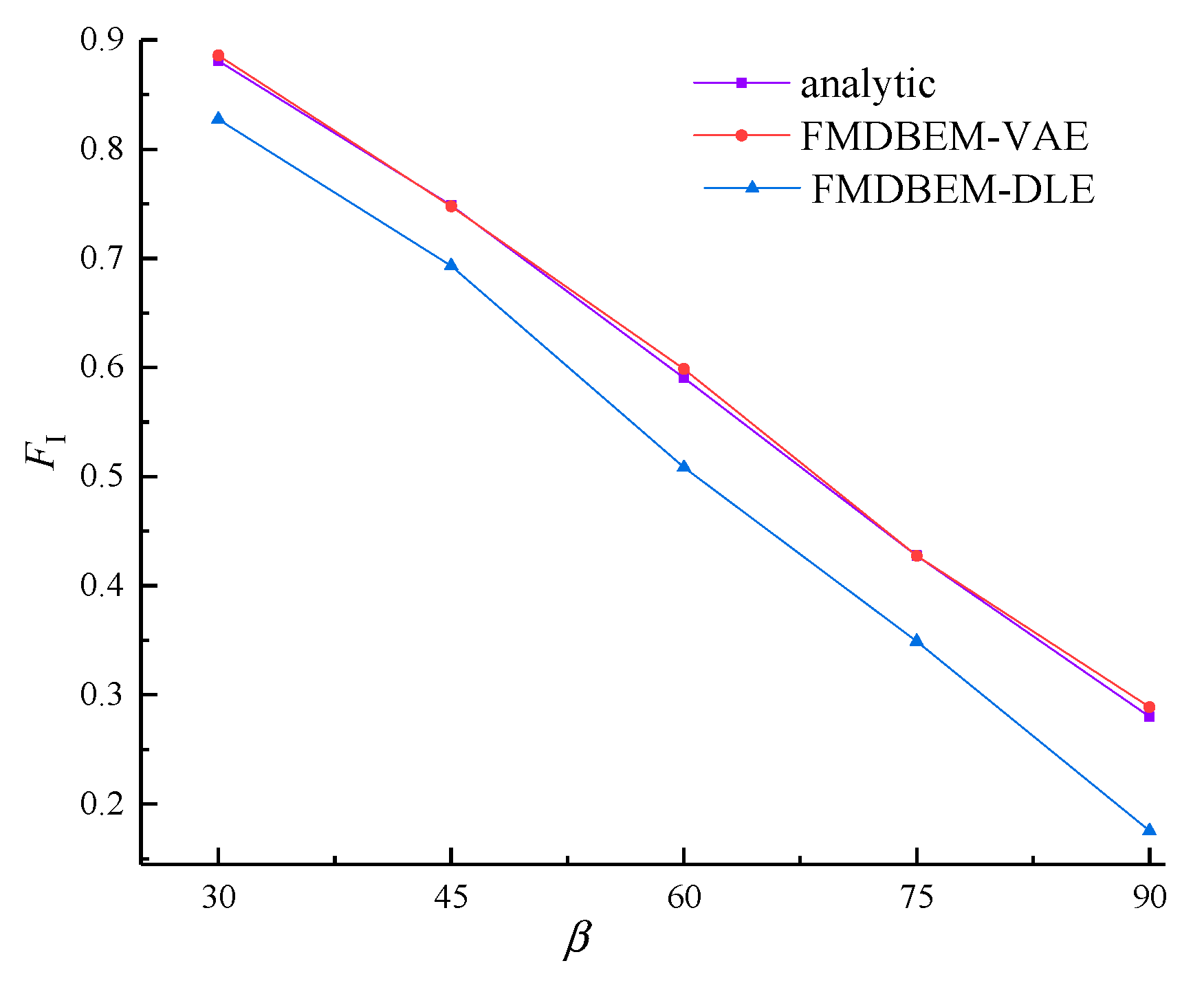
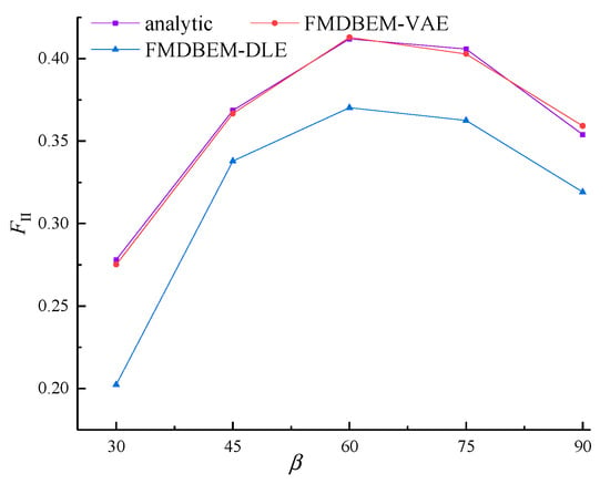
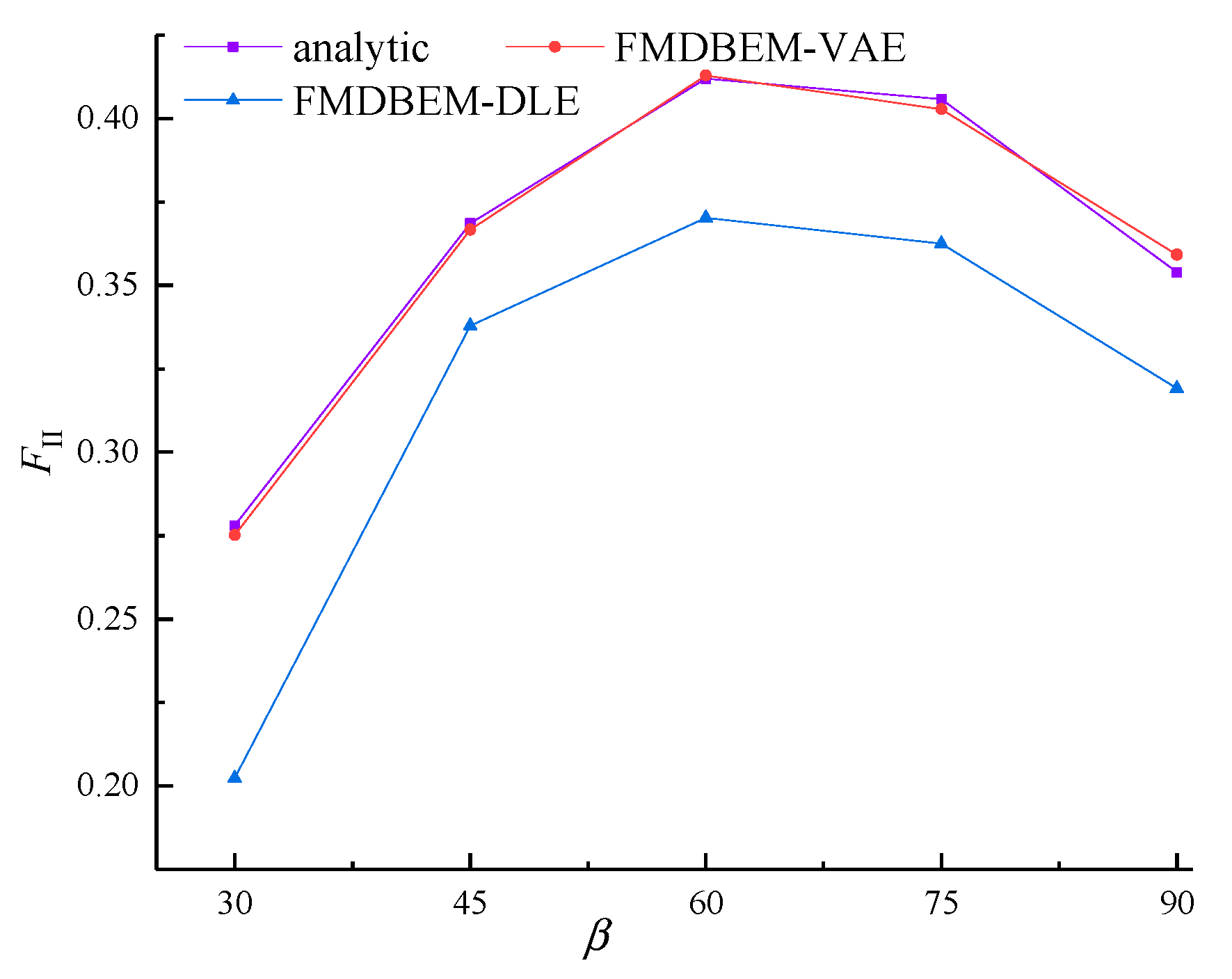
Figure 5 and Figure 6 show FI and FII under different angles , respectively. With the increase in , FI decreases, while FII increases first, and then decreases. The mutation of FII is nearly at . Compared with the analytical solutions, the FMDBEM-VAE provides more accurate results than the FMDBEM-DLE.
Figure 5.
The normalized stress intensity factor FI under different .
Figure 6.
The normalized stress intensity factor FII under different .
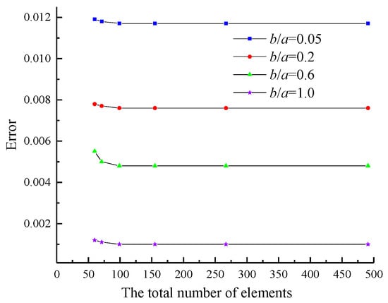
Next, the convergence of the FMDBEM-VAE is discussed, as seen in Figure 7. From Figure 7, we can see that the error of the FMDBEM-VAE approaches a fixed value under different b/a, which shows the FMDBEM-VAE has good convergence properties.
Figure 7.
The convergence of the FMDBEM-VAE.
4.2. A Rectangular Plate with Multiple Parallel Inclined Cracks
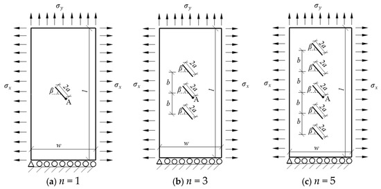
A rectangular plate with multi-parallel inclined cracks under tension is considered, as illustrated in Figure 8. The slant angle of the crack and the length 2a = 6 mm. The plate has a width of w = 50 mm and a height of l = 100 mm, the distance between the cracks b = 10 mm, , E = 21 , ν = 0.35, , B = 1.0, 2.0, and n is the number of cracks.
Figure 8.
Geometry of multi-parallel inclined cracks.
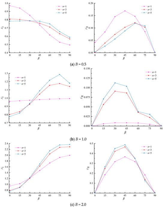
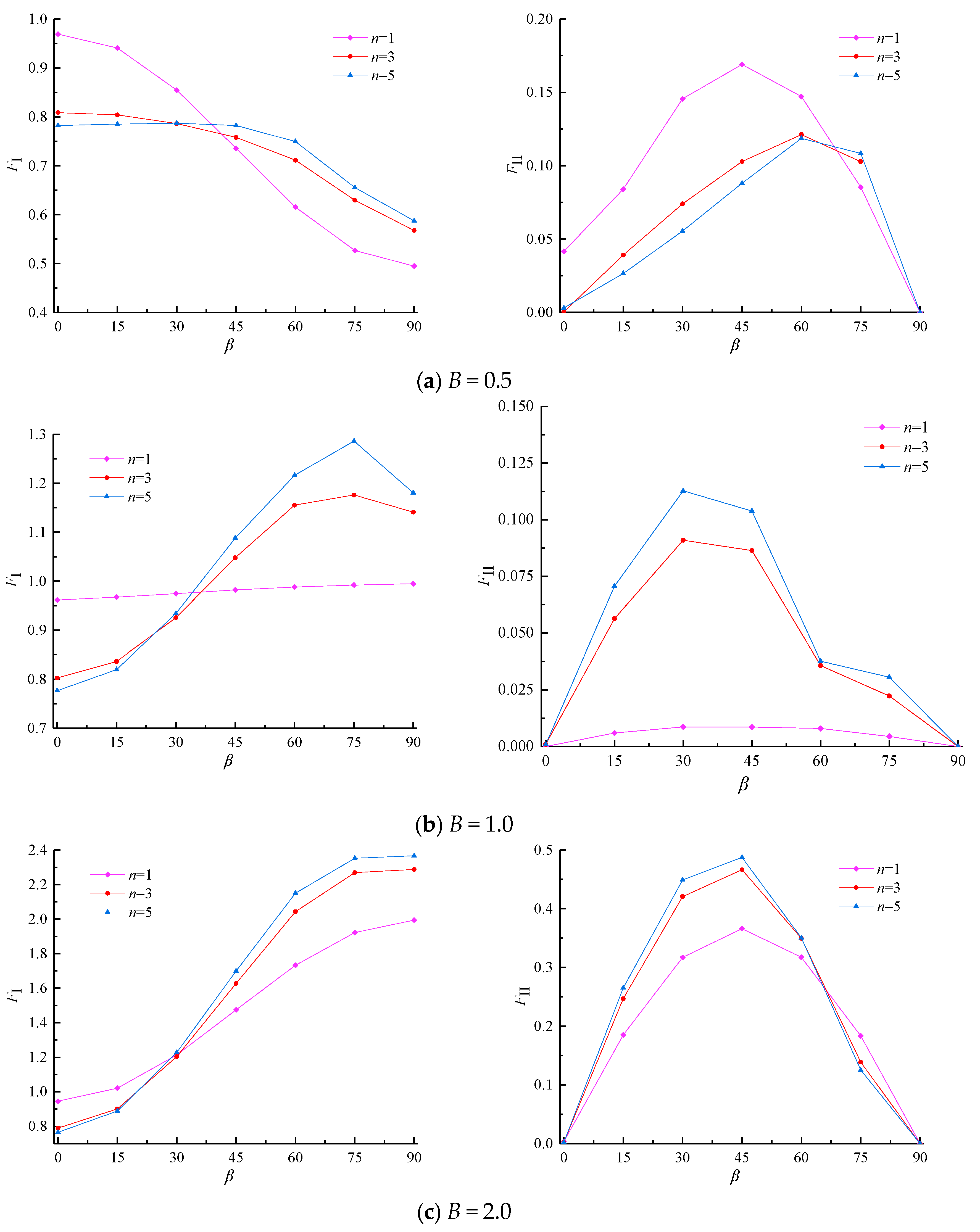
From Figure 9, it can be observed that when B is equal to 0.5, the FI of n = 1 is larger than the ones of n = 3 and 5 when β < , while the FI of n = 1 is smaller than the ones of n = 3 and 5 when β. When B is equal to 1.0 or 2.0, the FI of n = 1 is larger than the ones of n = 3 and 5 when β, while the FI of n = 1 is smaller than the ones of n = 3 and 5 when β > . This is because when β is small, the cracks are primarily subjected to the vertical load (), and their arrangement allows them to collectively support the vertical force. As a result, the greater the number of cracks, the lower the FI.
Figure 9.
The normalized stress intensity factor of multi-parallel inclined cracked structure.
With the increase in β, the cracks are primarily subjected to the horizontal load (), but their arrangement does not allow them to cooperate in supporting the horizontal force and even weakens the structure. Thus, the greater the number of cracks, the higher the FI.
In total, there are interactions between multiple cracks. When the number and the location of cracks change, the most unfavorable conditions of the structures also change.
4.3. A Rectangular Plate with Different Types of Defects
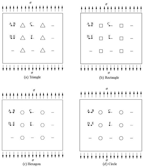
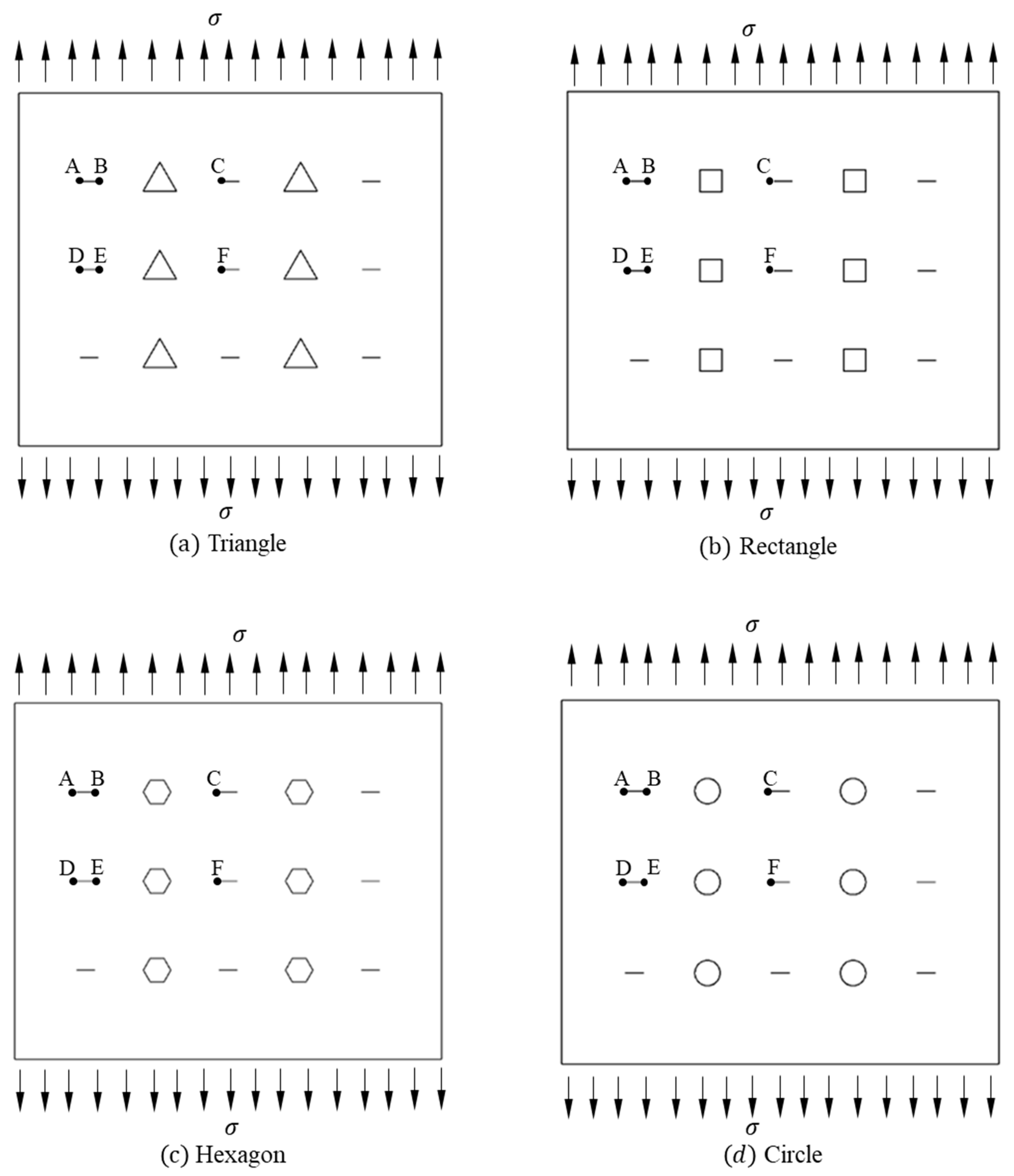
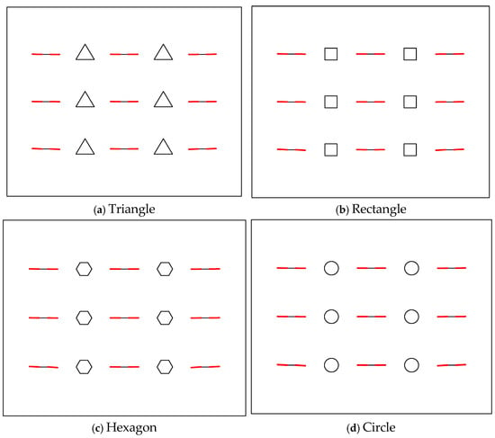
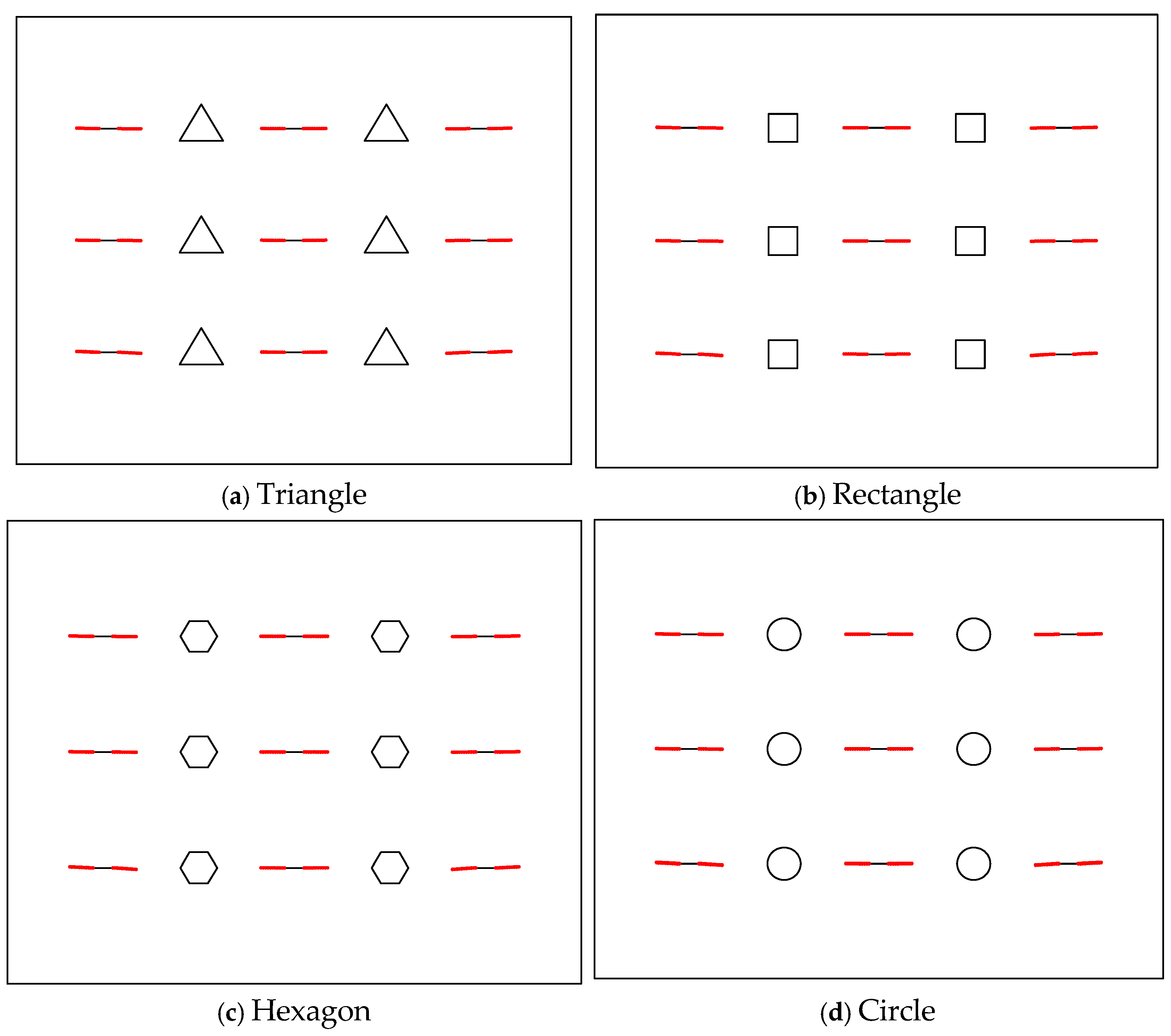
A rectangular plate with different types of defects under tension is considered, as illustrated in Figure 10. The length of the crack is 2 mm. The width and height of the plate is 40 mm × 40 mm, σ = 10 , Young’s modulus E = 21 , Poisson’s ratio ν = 0.35, fracture toughness is 100 N/mm1.5, and . Different defects are distributed between cracks, and the area of the defects is equal.
Figure 10.
Geometry of the rectangular plate with different types of defects.
The VAE is adaptable to V-notches with varying opening angles, necessitating only minor modifications to the stress exponents. The stress and displacement exponents differ for V-notches with various opening angles [25], as shown in Table 3.
Table 3.
Variable-order asymptotic terms.
Stress intensity factors play a fundamental role in crack growth processes. For each increment of the crack propagation, the stress intensity factors are evaluated. The effective stress intensity factor [28] of each crack tip is obtained by
where the crack initiation angle [28] can be determined based on the maximum circumferential stress criterion.
If the exceeds the material toughness , the crack will propagate forward along the direction of , resulting in the formation of a new multi-cracked structure. It should be noted that crack propagation does not occur when , and the simulation procedures of multiple-crack propagation can be seen in ref. [27] in detail.
Table 4, Table 5, Table 6, Table 7, Table 8 and Table 9 show the KI at node A~F under different propagation steps and different defects. The KI gradually increases with the increase in the crack propagation steps, indicating that the structure is becoming weaker. With different defects, KI exhibits the following phenomenon: triangle > rectangle > hexagon > circle. When the area of the defect is identical, the triangular defect is more likely to induce crack propagation, while the circular defect is more secure. The KI for the hexagonal and circular cases are almost the same, so a hexagonal defect can be replaced by a circular defect for the analysis of complex engineering problems. Additionally, the crack propagation paths after 10 incremental steps are shown in Figure 11.
Table 4.
The KI of node A under different propagation steps (N/mm1.5).
Table 5.
The KI of node B under different propagation steps (N/mm1.5).
Table 6.
The KI of node C under different propagation steps (N/mm1.5).
Table 7.
The KI of node D under different propagation steps (N/mm1.5).
Table 8.
The KI of node E under different propagation steps (N/mm1.5).
Table 9.
The KI of node F under different propagation steps (N/mm1.5).
Figure 11.
The crack propagation path after 10 increment steps.
5. Conclusions
The stress intensity factors of 2D elastic plates with multiple cracks are calculated in the present study. Some interesting conclusions can be drawn, as follow:
- The conventional discontinuous linear element struggles to capture the high gradient variation of the singular stress fields near the crack tip, while the novel variable-order asymptotic element can describe the singularity accurately.
- For the structure with multi-parallel inclined cracks, there are interactions between multiple cracks. When the crack distribution changes, the most unfavorable conditions of the structures also change.
- For cracks near different defects, the triangular defect is more likely to induce crack propagation, while the circular defect is more secure when the area of the defect is identical.
The present method can deal with the multiple cracks in a single domain accurately, more complicated cases such as random cracks and interface cracks in multi-material joints need to be considered carefully; this is our future work.
Author Contributions
Design, methodology, writing, C.L.; Editing, Y.M.; data curation, formal analysis, B.H.; Visualization, Z.N. All authors have read and agreed to the published version of the manuscript.
Funding
This work was supported by Natural Science Research Project of Anhui Educational Committee [No. 2024AH030010], the National Natural Science Foundation of China [No. 12202001] and the Doctoral Initiation Fund [No. 2020QDZ08] of AHJZU.
Data Availability Statement
The original contributions presented in this study are included in the article. Further inquiries can be directed to the corresponding author.
Conflicts of Interest
The authors declare no conflicts of interest.
References
- Yakoubi, K.; Montassir, S.; Moustabchir, H.A.; Elkhalfi Pruncu, C.I.; Arbaoui, J.; Farooq, M.U. An extended finite element method (XFEM) study on the elastic T-stress evaluations for a notch in a pipe steel exposed to internal pressure. Mathematics 2021, 9, 507. [Google Scholar] [CrossRef] [Scilit]
- Tian, R.; Zhou, M.Z.; Wang, J.T.; Li, Y.; An, H.B.; Xu, X.W.; Wen, L.F.; Wang, L.X.; Xu, Q.; Leng, J.L.; et al. A challenging dam structural analysis: Large-scale implicit thermo-mechanical coupled contact simulation on Tianhe-II. Comput. Mech. 2019, 63, 99–119. [Google Scholar] [CrossRef] [Scilit]
- Zhu, X.G.; Feng, C.; Cheng, P.D.; Wang, X.Q.; Li, S.H. A novel three-dimensional hydraulic fracturing model based on continuum-discontinuum element method. Comput. Methods Appl. Mech. Eng. 2021, 383, 113887. [Google Scholar] [CrossRef] [Scilit]
- Prassianakis, J.N.; Theocaris, P.S. Stress intensity factors at V-notched elastic, symmetri-cally loaded, plates by the method of caustics. Eng. Phys. J. Phys. D 1980, 13, 1043–1053. [Google Scholar] [CrossRef] [Scilit]
- Yao, X.F.; Yeh, H.Y.; Xu, W. Fracture investigation at V-notch tip using coherent gradient sensing (CGS). Int. J. Solids Struct. 2006, 43, 1189–1200. [Google Scholar] [CrossRef] [Scilit]
- Ayatollahi, M.R.; Nejati, M. Experimental evaluation of stress field around the sharp notches using photoelasticity. Mater. Des. 2011, 32, 561–569. [Google Scholar] [CrossRef] [Scilit]
- Bahrami, B.; Ayatollahi, M.R.; Torabi, A.R. Application of digital image correlation method for determination of mixed mode stress intensity factors in sharp notches. Opt. Lasers Eng. 2020, 124, 105830. [Google Scholar] [CrossRef] [Scilit]
- Shi, L.; Oyadiji, S.O. Determination of notch stress intensity factors for V-notched specimens under mode I loading using the 3D-Digital image correlation and strain energy approach. Theor. Appl. Fract. Mech. 2024, 130, 104307. [Google Scholar] [CrossRef] [Scilit]
- China Academy of Aeronautics and Astronautics. Stress Intensity Factors; Science Press: Beijing, China, 1993. (In Chinese) [Google Scholar]
- Chen, S.S.; Wang, W.; Zhao, X.S. An interpolating element-free Galerkin scaled boundary method applied to structural dynamic analysis. Appl. Math. Model. 2019, 75, 494–505. [Google Scholar] [CrossRef] [Scilit]
- Yao, S.L.; Cheng, C.Z.; Niu, Z.R.; Hu, Z.J. Evaluation of notch stress intensity factors by the asymptotic expansion technique coupled with the finite element method. Appl. Math. Model. 2018, 61, 682–692. [Google Scholar] [CrossRef] [Scilit]
- Gu, Y.; Zhang, C.Z. Novel special crack-tip elements for interface crack analysis by an efficient boundary element method. Eng. Fract. Mech. 2020, 239, 107302. [Google Scholar] [CrossRef] [Scilit]
- Benvenuti, E. An effective XFEM with equivalent eigen strain for stress intensity factors of homogeneous plates. Comput. Methods Appl. Mech. Eng. 2017, 321, 427–454. [Google Scholar] [CrossRef] [Scilit]
- Wen, L.F.; Tian, R.; Wang, L.X.; Feng, C. Improved XFEM for multiple crack analysis: Accurate and efficient implementations for stress intensity factors. Comput. Methods Appl. Mech. Eng. 2023, 411, 116045. [Google Scholar] [CrossRef] [Scilit]
- Noda, N.A.; Lan, X. Stress intensity factors for an edge interface crack in a bonded semi-infinite plate for arbitrary material combination. Int. J. Solids Struct. 2012, 49, 1241–1251. [Google Scholar] [CrossRef] [Scilit]
- Hamzah, K.B.; Nik Long, N.M.A.; Senu, N.; Eshkuvatov, Z.K. Stress intensity factor for multiple cracks in bonded dissimilar materials using hypersingular integral equations. Appl. Math. Model. 2019, 73, 95–108. [Google Scholar] [CrossRef] [Scilit]
- Liu, Y.J.; Li, Y.X.; Xie, W. Modeling of multiple crack propagation in 2-D elastic solids by the fast multipole boundary element method. Eng. Fract. Mech. 2017, 172, 1–16. [Google Scholar] [CrossRef] [Scilit]
- Romlay, F.R.M.; Ouyang, H.; Ariffin, A.K.; Mohamed, N.A.N. Modeling of fatigue crack propagation using dual boundary element method and Gaussian Monte Carlo method. Eng. Anal. Bound. Elem. 2010, 34, 297–305. [Google Scholar] [CrossRef] [Scilit]
- Cai, X.; Guo, Z. Coupled mechano-diffusion J-integral in active particles under the influence of binder. Eng. Fract. Mech. 2020, 231, 107031. [Google Scholar] [CrossRef] [Scilit]
- Clerici, D.; Mocera, F.; Pistorio, F. Analysis of fracture behaviour in active materials for lithiumion batteries. IOP Conf. Ser. Mater. Sci. Eng. 2022, 1214, 012018. [Google Scholar] [CrossRef] [Scilit]
- Shemesh, M.L. The M-integral for calculating intensity factors of an impermeable crack in a piezoelectric material. Eng. Fract. Mech. 2008, 75, 901–925. [Google Scholar]
- Gosz, M.; Moran, B. An interaction integral method for computation of mixed-mode stress intensity factors along non-planar crack fronts in three dimensions. Eng. Fract. Mech. 2002, 69, 299–319. [Google Scholar] [CrossRef] [Scilit]
- Zhou, B.; Xue, S.F. Displacement extrapolation method for stress intensity factor based on extended finite element method. Mech. Eng. 2007, 39, 371–378. (In Chinese) [Google Scholar]
- Liu, Y.J. Fast Multipole Boundary Element Method; Cambridge University Press: Cambridge, UK, 2009. [Google Scholar]
- Niu, Z.R.; Li, C.; Cheng, C.Z.; Hu, B. Interpolation Matrix Method for Ordinary Differential Equations and Its Mechanical Applications; University of Science and Technology of China Press: Hefei, China, 2023. (In Chinese) [Google Scholar]
- Hu, B.; Niu, Z.R.; Li, C.; Hu, Z.J. A fast multipole boundary element method based on higher order elements for analyzing 2-D elastostatic problems. Eng. Anal. Bound. Elem. 2021, 130, 417–428. [Google Scholar]
- Li, C.; Hu, B.; Niu, Z.R.; Meng, Y. An advanced fast multipole dual boundary element method for analyzing multiple cracks propagation. Eng. Fract. Mech. 2024, 311, 110547. [Google Scholar] [CrossRef] [Scilit]
- Sih, G.C. On the crack extension in plates under plane loading and transverse shear. J. Basic Eng. 1963, 12, 519–525. [Google Scholar]

Disclaimer/Publisher’s Note: The statements, opinions and data contained in all publications are solely those of the individual author(s) and contributor(s) and not of MDPI and/or the editor(s). MDPI and/or the editor(s) disclaim responsibility for any injury to people or property resulting from any ideas, methods, instructions or products referred to in the content. |
© 2025 by the authors. Licensee MDPI, Basel, Switzerland. This article is an open access article distributed under the terms and conditions of the Creative Commons Attribution (CC BY) license (https://creativecommons.org/licenses/by/4.0/).