


Abstract
Robotic belt grinding is an effective and widely adopted finishing method for superalloys, offering notable advantages such as high material removal capability, low heat input, and reduced workpiece damage. In addition, robots can readily integrate multiple sensors—such as infrared radiation cameras, force sensors, and high-speed cameras—which facilitate real-time monitoring of the grinding process and thereby enhance grinding quality control. With the establishment and continuous advancement of large-scale artificial intelligence (AI) data models, new breakthroughs have emerged in the optimization of robotic grinding processes. Owing to its dexterous workspace and advantages in high flexibility and cost-effectiveness, robotic belt grinding has become a critical process for the precision forming of complex curved components such as aero-engine blades and blisks. However, factors such as the limited absolute accuracy of industrial robots, time-varying grinding contact states, and significant transient boundary effects make it difficult for the current constant-parameter open-loop machining mode to simultaneously meet the demands for high material removal efficiency and high surface integrity on complex profiles. This paper systematically reviews the technologies for precision control and process optimization of robotic belt grinding aimed at pointwise precise material removal. First, the structural composition of the robotic belt grinding system and the material removal mechanism are analyzed. Then, centered on the compensation concept, a hierarchical progressive technical framework is outlined, covering geometric calibration compensation, force/position hybrid online compensation, transient entry boundary compensation, and system-level comprehensive compensation of multi-source errors, with a comparison of the applicable scenarios and the effects on shape and property control at each level. Furthermore, under the support of effective compensation, the collaborative optimization methods of material removal modeling, multi-objective optimization of process parameters, force-constrained trajectory planning, and intelligent adaptive processes are elaborated. Finally, current technical bottlenecks are summarized, and future trends in next-generation adaptive grinding technology driven by digital twins and embodied intelligence are envisioned. This review aims to provide a systematic theoretical reference for the high-precision and intelligent upgrading of robotic precision grinding systems.
1. Introduction
With the continuous enhancement of performance requirements for core components in aerospace, energy and power, and other fields, complex curved-surface parts such as blades, blisks, and casings are predominantly fabricated from difficult-to-machine superalloys or titanium alloys. Their final forming accuracy and surface integrity directly determine the service life and aerodynamic efficiency of the equipment [1,2]. In many cases, grinding is the only economical method for processing such difficult-to-cut materials with free-form surfaces [3]. The precision surfaces obtained by grinding are far superior to those produced by turning or milling [4,5,6].
Despite the emergence of numerous advanced finishing technologies, grinding has remained an indispensable process for millennia. Belt grinding, as a flexible machining technique that combines the characteristics of grinding and polishing, has become a key method for the precision final machining of such components by virtue of its cold processing, elastic contact, and strong conformability. For a long time, grinding processes have been performed manually by workers using grinding machines. During manual grinding, operators adjust the magnitude and position of the grinding force through visual feedback and manual motion control. However, even experienced workers find it difficult to ensure consistent product quality. In addition, the challenges of ensuring workplace safety and the low work efficiency have also troubled the machining process [7]. With the development of robotics and automation technology, robotic grinding can help workers stay away from hazardous operating environments, improving both machining efficiency and product quality [8]. Integrating a belt grinding device with an industrial robot not only inherits the process flexibility of belt grinding but also significantly expands the accessible machining space and reduces the cost of specialized tooling, thus offering a new pathway for the efficient, low-cost precision machining of large and complex components [9]. The integration of industrial robots and sensors forms a complete intelligent grinding process that can, to a certain extent, replace manual grinding. Owing to its high machining efficiency and grinding stability, it holds broad application prospects in modern manufacturing [10].
However, the robotic belt grinding system faces significant technical bottlenecks in its progression toward “precision controllability.” The repeatability of industrial robots is acceptable, yet their absolute positioning accuracy typically remains only at the sub-millimeter to millimeter level [11]. Moreover, the low stiffness inherent in the cantilevered serial structure renders the end-effector highly susceptible to deformation and vibration under contact grinding force disturbances, leading to non-negligible deviations between the actual grinding position and the pre-planned trajectory [12,13]. In addition, time-varying and nonlinear factors—such as the variation in material removal capability caused by belt wear, changes in the contact state between the contact wheel and the workpiece surface, and the transient over-cutting effect at the entry segment of the tool path—further exacerbate the degradation of process controllability [14,15]. The “constant-parameter open-loop grinding” mode currently widely adopted in engineering practice, which applies uniform processing parameters to the entire surface, is simple to implement but struggles to simultaneously meet the multi-objective requirements of high material removal efficiency, low surface roughness, and high profile accuracy when faced with complex profiles characterized by varying curvatures and uneven stock allowance [16]. How to achieve precise pointwise material removal control while maintaining the flexibility and efficiency of the robot has thus become a core scientific issue limiting the deeper application of robotic belt grinding in the field of precision manufacturing.
In response to the above issues, extensive research has been conducted in both academia and industry, with the technological evolution exhibiting a trajectory from “offline calibration compensation” to “online sensing and regulation”, and from “single-factor correction” to “comprehensive compensation of multi-source errors”. At the geometric level, robot kinematic calibration and hand-eye system spatial transformation compensation have preliminarily addressed the absolute positioning of the grinding tool [17]; at the mechanical level, the introduction of impedance control, admittance control, and passive compliant mechanisms has effectively mitigated the disturbance of contact force fluctuations on material removal consistency [18,19]; in recent years, compensation strategies targeting transient entry boundary effects and system-level error coupling have also begun to attract attention [20]. Concurrently, research on process parameters and trajectory planning based on material removal mechanism modeling and employing multi-objective optimization has provided a goal-oriented optimization space for the implementation of compensation strategies [21,22,23]. However, existing studies predominantly focus on single compensation links or isolated process parameter optimization, lacking a systematic review and synthesis of the complete technical chain encompassing “from system geometric calibration to transient process control, and from single-point force/position compensation to full-surface collaborative optimization.” In particular, the relationship between compensation strategies and process optimization is not merely a simple sequential superposition; rather, there exists a deep synergistic mutual feedback at the mechanism level. Effective compensation is the prerequisite for the accurate mapping of process models, while rational process planning can, in turn, reduce the stringent demands on compensation bandwidth. Clarifying this synergistic relationship is of significant value for guiding the integrated design and process decision-making of robotic belt grinding systems.
In view of this, this paper systematically reviews the research progress on precision machining technology for robotic belt grinding, taking “compensation strategies as the main thread and process optimization as the auxiliary thread.” The main contributions and organizational structure are as follows: Section 2 outlines the basic configuration and material removal mechanism of the robotic belt grinding system; Section 3, as the core of this paper, constructs and elaborates a framework covering force-parameter-based compensation, speed compensation, force/position hybrid compensation, and comprehensive compensation; Section 4 expounds the process modeling methods under the support of effective compensation; Section 5 summarizes the current technical challenges and envisions the trends of next-generation adaptive grinding technology driven by digital twins and embodied intelligence. Figure 1 showed panoramic architecture diagram of multi-level compensation and process collaborative optimization for robotic belt grinding. This diagram illustrates the hierarchical relationship from multi-level compensation strategies (geometric, force, velocity) to collaborative process optimization (material removal modeling, parameter optimization, trajectory planning), which serves as the structural roadmap for the entire review.
Figure 1.
Panoramic architecture diagram of multi-level compensation and process collaborative optimization for robotic belt grinding.
To clarify the specific scope and boundaries of this work, its structure is contrasted against the existing literature. While previous reviews in robotic machining or surface finishing often focus on general process parameters, surface integrity, or isolated control loops, this review specifically traces the technical evolution from independent single-parameter regulation to multi-parameter collaborative control. Furthermore, it categorizes mainstream material removal modeling into empirical, mechanics-based, and data-driven methods. Table 1 outlines these distinctions against recent prominent overviews across key dimensions.
Table 1.
Comparison between the current work and existing review papers.
2. Fundamentals of the Robotic Belt Grinding System
Robotic belt grinding is a complex process involving multi-body kinematics, contact mechanics, and micro-scale material removal. To facilitate an in-depth investigation into the sources of systematic errors and the intrinsic mechanisms of process optimization, this section elaborates from three dimensions: the physical layer, the mechanism layer, and the model layer. First, the basic hardware composition and integration configurations of the grinding system are outlined. Second, the microscopic material removal mechanism under the elastic contact between the workpiece and the abrasive belt is analyzed. Finally, a fundamental mathematical and physical modeling overview of the key variables in the grinding process—such as material removal rate and contact dynamics—is presented. These system fundamentals not only serve as the prerequisite for revealing the accumulation pattern of machining errors, but also provide the necessary theoretical cornerstone for the subsequent construction of the multi-level compensation framework and the implementation of process collaborative optimization.
2.1. Basic Configuration
A typical robotic belt grinding system consists of an industrial robot, a belt grinding device, a force-controlled end-effector, a sensor-based measurement system, and auxiliary equipment (for cooling, dust extraction, loading/unloading, etc.). According to the relative arrangement between the workpiece and the grinding device, the system architecture can be classified into two types: the “workpiece-moving type,” in which the robot holds and moves the workpiece against a stationary belt grinding machine, suitable for small- and medium-sized workpieces; and the “tool-moving type,” in which a belt grinding device is mounted on the robot end-effector to process a fixed workpiece, suitable for large and complex components. Modern intelligent grinding systems often further integrate online sensing devices such as 3D scanners, force sensors, and vision cameras on top of the above basic configuration, forming a closed-loop machining system with offline programming, online calibration, intelligent path learning, and dynamic compensation capabilities.
An intelligent robotic grinding system is primarily composed of two main parts: an intelligent control model and hardware equipment. The hardware equipment includes actuators responsible for executing machining commands and sensors for acquiring various signals; the control model processes and analyzes these signals and generates control commands based on the analysis results and preset parameters, thereby achieving closed-loop and intelligent grinding control.
Figure 2 illustrates the control architecture of the intelligent grinding system. Grinding tools, typically represented by grinding wheels, are usually installed around the robot, and an automatic feeding device enables precise positioning and transfer of the workpiece. In one common configuration, the robot is responsible for gripping and fixing the workpiece; in another configuration, tools such as a micro belt sander are mounted on the end of the robotic arm, while the workpiece is placed on a dedicated platform. The intelligent grinding system integrates a large number of sensors for real-time monitoring and control of the grinding process. To comprehensively capture grinding-related signals, an increasing number of sensors are deployed, such as acoustic emission sensors, accelerometers, force sensors, infrared cameras, and thermocouples, all of which have proven effective in grinding process monitoring. Furthermore, a data acquisition system is responsible for signal conditioning and converting continuous analog signals into digital signals. A high-performance industrial-grade personal computer provides real-time data processing and control capability for the entire system.
Figure 2.
Control architecture of the intelligent robotic grinding system.
2.2. Fundamentals of Belt Grinding Mechanism
Material removal in belt grinding is essentially a comprehensive manifestation of micro-cutting, plowing, and rubbing behaviors produced by a large number of randomly distributed abrasive grains interacting with the workpiece surface under relative motion and normal load. Unlike rigid grinding wheels, belt grinding relies on a multi-layer elastomer consisting of a rubber contact wheel, the belt backing, and the adhesive bond, which imparts a compliant surface-contact characteristic to the contact zone. This feature provides unique advantages in the precision machining of difficult-to-cut materials such as titanium alloy TC4, combining cold grinding with simultaneous material removal and polishing [25]. At the scale of a single abrasive grain, the grain penetration process sequentially undergoes three stages: rubbing, plowing, and cutting (see Figure 3 and Figure 4). As illustrated in the theoretical model, the micro-interaction between a single abrasive grain and the workpiece is primarily governed by the cutting depth of the grain, denoted as . This parameter increases progressively from zero to its peak value, which corresponds to the maximum undeformed chip thickness, . At extremely small penetration depths, only elastic deformation and friction occur; as the normal force increases, plastic flow leads to the material pile-up; only when the penetration depth exceeds a critical value does material removal take place through shear slip to form chips [26]. In actual grinding, abrasive grains of different heights on the belt surface may be at different stages, and material removal is primarily attributed to the cutting stage. Based on this understanding, some researchers have idealized the abrasive grains of silicon carbide hollow sphere belts as perfect spheres and established a quantitative relationship between the material removal volume per grain and the normal force, rubbing distance, and workpiece hardness. This relationship is consistent in form with the Archard wear equation, providing a theoretical underpinning for understanding the removal mechanism at the microscale.
Figure 3.
Schematic diagram of single abrasive grain belt grinding [26].
Figure 4.
Monocrystalline cutting at each stage [26].
The elastic contact characteristic is the fundamental feature that distinguishes belt grinding from rigid grinding. Figure 5 illustrates the macroscopic grinding process and the material removal under machining parameters [27]. Under the action of normal grinding force, a surface contact is formed between the contact wheel and the workpiece, leading to a highly non-uniform pressure distribution within the contact area. Classical Hertzian contact theory describes this as a semi-ellipsoidal distribution, wherein the pressure peaks at the contact center and gradually decreases toward the edges [28]. However, Hertzian theory is predicated on ideal assumptions of smooth surfaces, frictionless conditions, and small deformations. In actual belt grinding, the presence of discrete abrasive grain contacts, friction, and thermo-mechanical coupling effects has led some scholars to question its direct applicability. To describe the contact pressure field more accurately, recent studies have introduced dimensionality reduction contact methods, mapping the three-dimensional elastic contact problem into a one-dimensional Winkler elastic foundation model, which significantly reduces computational complexity while maintaining high accuracy.
Figure 5.
Schematic of macroscopic grinding process and material removal [27].
As a consumable, the wear process of the abrasive belt directly determines the machining consistency and process cost. Studies indicate that abrasive belt wear primarily manifests in three fundamental forms: shedding wear, dulling wear, and loading wear [25]. Shedding wear typically occurs in the initial wear stage; when the load applied to an abrasive grain exceeds the bonding strength of the binder, the intact grain detaches from the substrate, resulting in a complete loss of cutting ability in that specific localized area. Dulling wear emerges during the steady wear stage and can be further subdivided into attritious wear (the gradual flattening of the grain tops) and fracture wear (the localized fracture of grains under alternating stress to form new cutting edges). The latter exhibits a certain “self-sharpening” effect, which can delay the overall failure of the abrasive belt to some extent. Capping wear (or clogging) mostly occurs in the final wear stage, where chips and fractured grain fragments fill the chip clearance space and cover the surfaces of the dulled grains, forming a clogged layer on the belt. At this point, the grinding action degenerates into rubbing and plowing, leading to a sharp rise in grinding temperature and a significant drop in the material removal rate. The normal grinding force and belt linear velocity are critical process parameters influencing the wear rate. An increase in these parameters accelerates the wear process by elevating the load per unit area and the thermal contact frequency, respectively. Consequently, a balance must be struck between material removal efficiency and abrasive belt life during practical process planning [29].
Zhao et al. [30] further unveiled the evolutionary characteristics of Aggregated Abrasives (AAs) during the grinding process based on fracture mechanics theory, noting that abrasive frictional wear primarily involves fatigue spalling, micro-fracturing, and macro-fracturing. This process not only alters the abrasive grain geometry but also dynamically regulates the active cutting-edge density via “self-sharpening,” thereby influencing the material removal mechanisms.
The single-grain cutting model (Figure 4) and wear mechanism (Figure 5) plot the boundary where the process shifts from sliding to actual cutting, and track how the tool degrades from grain fracture to flattening. A common limitation of these models is that they assume perfect grain shapes, which fails to capture the chaotic surface of a clogged, worn belt in real operations. These diagrams support our evaluation by showing why simple flat-specimen tests cannot predict the time-varying tool wear seen on complex components.
Material removal rate (MRR) serves as a paramount indicator in the process planning of abrasive belt grinding. The factors influencing MRR encompass a multitude of aspects, including process parameters (e.g., normal force, belt linear velocity, and feed rate), abrasive belt characteristics (e.g., abrasive material, grit size, and grain arrangement), workpiece properties (e.g., hardness and thermal conductivity), and dynamic elements (e.g., wear state and contact wheel deformation). In addressing this complex, highly nonlinear system, the prevailing methodology involves the continuous refinement of predictive models based on varying parameters. Historically, modeling approaches have primarily evolved along three trajectories. The first comprises empirical models based on the Preston equation or the Archard wear equation, which offer mathematical simplicity but lack mechanistic interpretability. The second involves physical models grounded in Hertzian contact theory and grinding kinematics, which excel at elucidating the relationship between contact pressure distribution and material removal profiles. The third encompasses data-driven models empowered by machine learning, such as Support Vector Regression (SVR), Gradient Boosting Decision Trees (GBDT), and deep learning algorithms [31,32,33].
To establish a rigorous physical boundary for the reviewed mathematical and physical models, it is essential to explicitly distinguish robotic belt grinding from other relevant material removal or modification processes, including rigid wheel grinding, robotic milling, polishing, and burnishing. Specifically, robotic belt grinding is fundamentally governed by a flexible-contact state dictated by contact wheel elasticity, belt backing compliance, rapid progressive abrasive wear, and distributed multi-grain engagement. This inherent compliance makes it physically improper to directly transfer classical rigid-contact kinematics (common in milling or rigid wheel grinding) or non-removal elastic-plastic contact mechanics (common in burnishing) to the belt grinding system without mathematical modification. Therefore, while rigid milling or grinding models can offer structural chatter compensation frameworks or micro-level geometric grain engagement reference, their mechanistic force removal equations are non-transferable due to the absence of tool compliance. Similarly, polishing models based on pure force-velocity Preston equations apply only to micro-scratching but cannot handle macro-scale removal or posture errors under high cutting depths. Lastly, burnishing involves zero material removal, meaning its models can only guide the final subsurface residual stress constraints rather than material removal evolution.
2.3. Mathematical and Physical Modeling of Abrasive Belt Grinding
To quantitatively describe material removal, grinding force response, and the evolution of surface integrity in the abrasive belt grinding process, researchers have established various mathematical models. Different machining methods and process parameters exert distinct effects on grinding outcomes [24]. In terms of material removal rate modeling, the classical empirical formula can be traced back to the Preston equation, which characterizes the material removal depth per unit time, dt/dh, as a linear function of grinding pressure and relative velocity , expressed as
Here, denotes the Preston coefficient, which comprehensively encapsulates influencing factors such as abrasive grain characteristics, workpiece material properties, and cooling conditions [34,35]. However, the predictive accuracy of this linear model is limited under varying contact conditions. To address this limitation, Hammann et al. [36,37] proposed a modified‘ formulation incorporating the belt linear velocity Vs, workpiece feed rate Vw, normal grinding force Fn, and grinding width Lb. Subsequently, Cabaravdic [38] further generalized it into a local material removal model in the form of a power function: , where likewise denotes the material removal depth, Cg is the grinding modification constant, and the exponents α, β and +γ are determined through experimental data regression.
From the perspectives of microscopic grain kinematics and contact mechanics, Yang et al. [39] developed an analytical material removal rate model predicated on the assumption of a single spherical abrasive grain. This study initially conceptualized the cutting path of an individual abrasive grain as a semi-ellipsoidal cone. By integrating Archard’s wear law, it derived a proportional relationship linking the material removal volume to the normal force, grinding length, and workpiece hardness, expressed as , where represents the material removal volume, is the wear coefficient, is the normal grinding force, denotes the grinding length, and is the Brinell hardness of the workpiece. To overcome the limitation of classical Hertzian theory, which is strictly applicable only to small-deformation conditions, the research further introduced a dimensionality reduction method. This approach mapped the three-dimensional elastic contact problem onto a one-dimensional Winkler linear spring model, thereby deriving an analytical expression for the pressure distribution within the contact zone: , where is the local contact pressure at coordinate , represents the effective elastic modulus of the contact pair, denotes the contact semi-width, and is the equivalent radius of the contact wheel, thereby bridging the gap between macro- and micro-mechanics, thereby bridging the gap between macro- and micro-mechanics. To address complex free-form surfaces, Ren et al. [40] proposed a material removal simulation framework based on surfel representation and local process models. By employing Support Vector Regression (SVR) as a surrogate for the Finite Element Method (FEM) in pressure distribution calculations, the computational efficiency was enhanced by orders of magnitude—reducing the time from several minutes to mere seconds—while maintaining prediction errors within 5%. Qi et al. [41] developed a novel comprehensive framework to predict the surface roughness of Inconel 718 processed by an integrated robotic belt grinding and polishing system. By utilizing an expansion cavity model and Hertzian theory to predict the roughness of the hardened polished surfaces, this work provides a new pathway for high-precision surface quality prediction during integrated robotic finishing processes.
Accounting for abrasive frictional wear and grain pull-out, the time-varying attenuation of the material removal capability is expressed through the degradation of the removal coefficient:
where is the instantaneous material removal coefficient at cumulative grinding time t, is the initial removal coefficient of the sharp belt, is the residual removal coefficient at the steady-state wear stage, represents the wear attenuation factor, and and denote the normal contact force and belt linear velocity, respectively.
Mathematically, the time-dependent coefficient serves as the macroscopic integrator of these three coupled wear modes. Specifically, continuous attritious wear reduces the active grit sharpness, causing a steady decline in , while micro-fracturing provides localized self-sharpening effects that temporarily alter the decay rate. Ultimately, severe grain shedding leads to an accelerated, non-linear drop in material removal capability. Consequently, the trajectory of exhibits distinct non-linear, multi-stage degradation characteristics across the belt lifespan.
Grinding force control and trajectory compensation modeling constitute another cornerstone for ensuring machining accuracy. Impedance control characterizes the robot-environment contact system as an equivalent second-order mass-spring-damper system, whose dynamic equation can be expressed as
where , , and denote the target inertia, damping, and stiffness matrices, respectively; e = xd − x represents the position error; is the actual contact force; and is the desired force [42]. To mitigate the issues of over-grinding or under-grinding caused by the deviations between 3D CAD models and the actual profiles of irregular castings, Meng et al. [43] introduced a deep genetic algorithm within the impedance control framework for force tracking compensation. In this approach, the theoretical grinding trajectory is first extracted from the workpiece CAD model. Subsequently, the contact force error is captured in real-time via a six-axis force sensor, and the trajectory points are iteratively optimized through the selection, crossover, and mutation operations of the genetic algorithm. Addressing the problem of non-uniform material removal caused by sharp variations in contact states during compliant robotic belt grinding, Xiao et al. [44] established a material removal profile model based on the flexible deformation of the contact wheel and dynamic pressure distribution.
As a critical time-varying factor in the grinding process, the precise modeling of abrasive belt wear holds paramount engineering significance for ensuring machining dimensional consistency and surface quality stability. Through experimental observations, Hui et al. [24] categorized abrasive belt wear forms into shedding wear, dulling wear, and adhesive wear. Furthermore, they pointed out that during the steady wear stage, the abrasive belt wear height δ exhibits an approximately linear evolution with respect to the grinding time t, which can be expressed as
where δ0 denotes the initial wear height of the abrasive belt, and represents the steady-state wear rate characterizing the speed of wear progression. Further research demonstrates that the steady-state wear rate is positively correlated with the normal grinding force and the belt linear velocity . This relationship can be quantitatively described as: and the belt linear velocity . This relationship can be quantitatively described as: .
Tao et al. [45] proposed a dimensionless wear factor, , to characterize the degree of abrasive belt wear based on the evolution characteristics of the Preston coefficient (where denotes the initial Preston coefficient of a new belt). Following calibration through dwell grinding experiments, the study scientifically partitioned the entire belt service life into three stages: the initial wear stage (0 < k ≤ 0.5), the steady wear stage (0.5 < k ≤ 0.7), and the accelerated wear stage (k > 0.7). Regarding surface integrity modeling, the precise prediction of residual stress is pivotal for ensuring the service performance of components. Their systematic investigation into the residual stress distribution of GH4169 alloy after grinding at different wear stages revealed that the surface residual stress along the grinding direction, σx, transitions from compressive to tensile stress as belt wear intensifies. Experimental measurements indicated that the average grinding force ratios, μ = Ft/Fn (where Ft represents the tangential grinding force), for the initial, steady, and accelerated wear stages were 0.569, 0.535, and 0.523, respectively, with corresponding maximum grinding temperatures θmax of 70.71 °C, 73.31 °C, and 78.99 °C. Based on thermal-mechanical coupling analysis, the study established an empirical predictive model for grinding-induced residual stress:
where represents the surface residual stress in the -direction, denotes the friction coefficient (or a specific process parameter), signifies the grinding temperature (or temperature rise) , and are calibration constants related to the workpiece material. Furthermore, Huang et al. [2], in their comprehensive review, systematically summarized residual stress prediction models based on the Finite Element Method (FEM) and Artificial Neural Networks (ANN). They explicitly pointed out that the synergistic coupling of multiple physical fields—including thermal, stress, and phase transformation fields—represents a pivotal research direction for further enhancing the prediction accuracy of residual stresses.
To provide a rigorous physical and applicability boundary for the mathematical paradigms reviewed in this section, it is essential to evaluate their operational constraints. These models—spanning from contact mechanics and material removal to dynamic control and surface integrity—possess highly distinct theoretical foundations and calibration sensitivities. Table 2 presents a comprehensive comparison of these foundational mathematical models, systematically delineating their core assumptions, experimental calibration requirements, validity ranges (including explicit failure conditions), and inherent limitations.
Table 2.
Comprehensive comparison of foundational mathematical models in robotic grinding.
In summary, the modeling framework for abrasive belt grinding has progressively evolved from isolated empirical formulas into a multi-scale, multi-physics coupled system that encompasses material removal, force control response, wear evolution, and surface integrity. The deep integration of mechanistic modeling and data-driven approaches is emerging as a critical technical trajectory for improving both the predictive accuracy and engineering applicability of these models.
3. Progress in Multi-Level Compensation Strategies for Robotic Belt Grinding
3.1. Force-Parameter-Based Compensation Strategies
Grinding force serves as the determinative process variable that dictates material removal consistency, surface integrity, and machining efficiency in robotic belt grinding. Due to the limited absolute positioning accuracy and low structural stiffness of industrial robots, coupled with the elastic deformation of the contact wheel-belt system and the “giving-way” effect (deflection) of thin-walled blades, the grinding force exhibits pronounced nonlinearity and time-varying characteristics in both spatial distribution and temporal evolution. Centering on the precise perception and closed-loop compensation of force parameters, the academic community has established a progressive research framework evolving from “constant normal force control” and “impedance control architectures” to “tangential force ratio optimization” and, ultimately, “force fluctuation suppression.”
- Constant Normal Force Compensation
Constant normal force compensation represents the most widely adopted force-parameter-based strategy. Its technical approaches can be categorized into two primary types: passive compliance compensation and active force control compensation. Passive compliance compensation relies on the elastic deformation of mechanical devices themselves to absorb force fluctuations, eliminating the need for high-frequency signal feedback. Conversely, active force control leverages feedback from force sensors and employs algorithms—such as fuzzy PID or impedance control—to achieve real-time adjustment of the grinding force.
(1) Regarding passive compliance, Wang et al. [46] designed a compliant grinding device integrated with a damping mechanism. By effectively transforming the high environment stiffness of the contact wheel-workpiece interface into the lower stiffness of the damper system, the impact of displacement-induced disturbances on the normal force was reduced by nearly an order of magnitude, resulting in a 64.81% improvement in force control precision. To overcome the inherent limitations of passive compliance in terms of adaptability (Figure 6 illustrates the mechanical architecture and equivalent model of this passive compliance device), Xu et al. [47] proposed an active force control strategy combining force/position hybrid control with PI/PD algorithms. This approach effectively suppresses systemic errors through gravity compensation and sensor zero-drift suppression, successfully restricting normal force fluctuations to within ±5 N. While the aforementioned methods employ a globally uniform target force, Wang et al. [48] (2022) anoted that for blades with sharply varying curvatures, the ideal normal force at different cutter contact (CC) points differs significantly; a uniform constant force would lead to over-grinding or under-grinding at regions of sudden curvature change. Consequently, they proposed a selective force control method that calculates the ideal force point-by-point based on the principal curvature radius and machining allowance, followed by regional partitioning. This method improved the force control precision across four distinct blade regions by 50% to 80%. When extending the grinding scenario to blisks, the narrow channels necessitate a tilted orientation of the grinding head. Xiao et al. [49] discovered that during tilted grinding, a coupling exists between the normal force and the trajectory, where distortions in the contact facet shape lead to non-uniform material removal. By optimizing the contact wheel to a spherical shape and redefining the tool coordinate system (TCS), they largely neutralized the influence of orientation on the contact facet and established an adaptive variable impedance model to harmonize the relationship between force control and tilted trajectories. Collectively, these studies have progressively advanced normal force compensation from simplistic structural compliance to active closed-loop control, surface adaptation, and force-orientation coordination.
Figure 6.
Robotic belt grinding platform [46].
(2) Active force control compensation, on the other hand, actively adjusts the pose of the robot end-effector or the output of the actuator through real-time feedback from force sensors coupled with control algorithms. Zhang et al. [50] proposed a novel force/position control method that implements active force control by integrating fuzzy proportional-integral-derivative (FPID) control with conventional force/position control theory; the proposed method significantly mitigates the “sharp edge” phenomenon. Duan et al. [51] derived a mathematical model of normal grinding forces and introduced a fuzzy PID approach to enhance the stability of the force controller. Their experimental results demonstrated that the grinding force amplitude and the blade profile accuracy were maintained at 5 N and 0.08 mm, respectively. Xu et al. [47] developed a hybrid force/position control strategy based on PI/PD control, where the force control law is applied to the normal direction (Z-axis) of the tool coordinate system (TCS), while the position control law is assigned to the tangential direction (X-axis). By generating position corrections through PI regulation of the force error, the normal force is stabilized near the desired value, resulting in a reduction in surface roughness Ra from 0.774 μm to 0.355 μm. Additionally, Sheng [52] proposed a fuzzy adaptive hybrid impedance control scheme designed for the support side of mirror milling systems, which effectively addresses force support challenges in environments with time-varying stiffness.
- 2.
- Impedance Control Compensation.
Wang et al. [48] identified that the non-linear time-varying contact state is a critical factor hindering traditional robotic belt grinding from achieving precision machining of blades. To address this, they proposed a novel Selective Force Control (SFC) method based on regional partitioning (RD) and machining allowance, utilizing a self-developed adaptive impedance controller to enhance grinding accuracy for complex curved blades. An adaptive impedance controller with a neural network online compensation algorithm (AICNN) was developed. Validation tests conducted on four contour regions—the leading edge, trailing edge, suction side (convex), and pressure side (concave)—demonstrated that the force control precision using AICNN improved by 80.33%, 50.58%, 82.65%, and 69.01%, respectively, compared to cases without the controller. Building upon this, Min et al. [53] proposed an Adaptive Hybrid Impedance (AHI) control that combines the advantages of hybrid force/position control and impedance control. By implementing a selection matrix S = diag(0,0,1,0,0,0), they achieved decoupling between normal force control and tangential position control, with the root mean square (RMS) value of the force tracking error as low as 0.157 N. As shown in Figure 7, Luo et al. [54] proposed a method combining adaptive impedance control with dynamic trajectory planning, which achieves precise tracking of the normal grinding force by online estimation of the workpiece position and stiffness and dynamic correction of the current point while compensating for the next target point. This approach achieved a surface roughness of approximately 0.5146 μm and a grinding efficiency of 0.89 cm2/s. Zhu et al. [55] established a microscopic force model within the impedance control framework, encompassing sliding, plowing, and cutting components. This model reveals the evolution of the proportions of tangential force components under constant normal force conditions, providing a theoretical basis for the offline optimization of force control parameters. To improve the grinding process and achieve optimal results, Senoo et al. [56] designed and assembled a novel controllable compliant belt grinding mechanism equipped with a constant grinding force control system. Based on a proportional analysis of the valve and cylinder systems within the mechanism, a mathematical model for the normal grinding force was constructed. Subsequently, a fuzzy proportional-integral-derivative (PID) control strategy was proposed to address the uncertainties and non-linearities of the system. A Simulink force control process model was developed, achieving robust performance as evidenced by simulation results.
Figure 7.
Schematic of the novel force control strategy [54].
- 3.
- Tangential Force/Grinding Force Ratio Compensation
Distinct from constant normal force compensation, which focuses on the absolute value of the force, tangential-to-normal force ratio compensation emphasizes the ratioμ = Ft/Fn between the tangential force Ft and the normal force Fn. This ratio comprehensively reflects the cutting efficiency and the wear state of the abrasive belt, serving as a bridge between force parameters and tool condition. Under constant force control conditions, Zhu et al. [55] found that while active force control stabilizes the normal force, it causes the proportion of the sliding force within the total tangential force to increase significantly, whereas the proportion of chip formation decreases drastically, leading to a marked reduction in grinding efficiency. Considering the entry and exit paths, Yan et al. [57] established a tangential force model encompassing three components: sliding, plowing, and cutting. They pointed out that the cutting component dominates the entry path (exceeding 40%), making this segment prone to over-grinding. In contrast, on the normal and exit paths, the sliding component accounts for 62% and 65%, respectively, indicating that the abrasive grains primarily undergo sliding and plowing. Through orthogonal experiments, they discovered that the force ratio μ exhibits a nonlinear relationship with the normal force Fn and the contact wheel speed VC. Furthermore, significant differences in the force ratio were observed across different paths, suggesting that energy dissipation on the exit path is dominated by friction.
Zhang et al. [58] established a tangential force prediction model based on the normal distribution of abrasive grain protrusion height and Hertzian contact theory, deriving the quantitative relationship between the tangential force Ft and the normal force Fn, belt linear velocity VS, and feed rate Vf. Through orthogonal experimental calibration, they determined the relationship between the grain penetration depth δ and the contact pressure P0, finding that the grinding force ratio μ is primarily governed by the normal force Fn, while the influences of VS and Vf are relatively minor. Tao et al. [45] further correlated the force ratio with abrasive belt wear. Their wear experiments revealed that as the belt progresses from the initial wear stage through steady wear to the accelerated wear stage, the average grinding force ratio gradually decreases with the rise in the maximum temperature in the grinding zone. This phenomenon causes the surface residual stress of the workpiece to transition from compressive to tensile stress. This finding suggests that by monitoring the variations in the μ value online, the degree of belt wear can be indirectly assessed to implement compensation: when μ falls below a preset threshold, the normal force Fn is appropriately increased or the feed rate Vf is decreased to maintain a stable material removal rate (MRR). This strategy incorporates the time-varying factor of abrasive belt wear into the force-parameter compensation framework, addressing the deficiency of traditional constant-force control, which often overlooks tool condition degradation.
- 4.
- Force Fluctuation Amplitude Compensation
Force fluctuation amplitude compensation aims to suppress high-frequency force oscillations during the grinding process caused by insufficient robot stiffness, eccentric belt vibration, or sudden changes in surface curvature. Xu et al. [47] pioneered a hybrid active-passive force control strategy, which leverages active force control to ensure steady-state accuracy and uses passive compliant cylinders to suppress transient overshoot. By employing Kalman filtering to achieve the optimal fusion of these two information streams, they significantly reduced the standard deviation of force control. Figure 8a shows that when the robot is in a static state, the compensated force fluctuates slightly in any position. In contrast, when the robot moves with different axis rotations in a velocity of 50 mm/s, the compensated force, as shown in Figure 8b, fluctuates heavily in the range of 5 N to 5 N owing to the influences of the inertia force, random error, and measurement error, and this variation in force is decided by the whole robotic grinding environment. Domroes et al. [59] established a robotic grinding experimental system equipped with a six-axis force sensor to investigate the differences between position-controlled and force-controlled grinding programs. Although they analyzed the impact of force fluctuations on the material removal rate, the grinding modes remained inapplicable to complex components. Starting from the vibration mechanisms, Yang et al. [60] developed a spring-mass-damper model for pre- and post-grinding contact, decomposing the system response into free vibration zfree(t), accompanying vibration zacc(t), and forced vibration zfor(t). They identified that increasing the equivalent damping is the most effective way to suppress various types of vibrations. Accordingly, they proposed a variable-damping intelligent control strategy based on signal feature extraction, effectively reducing both the vibration amplitude and the over-cutting time. Furthermore, Winkler and Suchy [61] incorporated an integrator into a contour-following force control algorithm to minimize force control errors.
Figure 8.
Comparison of the compensated forces when the robot is in different states [47].
Force-parameter-based compensation is transitioning toward multi-parameter fusion, dynamic robustness, and tool wear integration. While constant normal force methods establish the operational baseline—utilizing passive compliance for high-volume manufacturing and active control for complex curved geometries—tangential-to-normal force ratios offer an indirect pathway to compensate for progressive belt wear. Furthermore, regulating force fluctuation amplitudes through vibration analysis suppresses transient instabilities during path entries, exits, and abrupt curvature transitions.
In summary, while the reviewed force control strategies—ranging from compliance mechanisms to active hybrid control—significantly enhance the robot’s tracking capabilities, a fundamental limitation remains overlooked: macroscopic force is merely a proxy variable, not a direct guarantee of uniform material removal. In actual belt grinding, material removal depth is locally governed by pressure distribution and tool cutting efficiency. Even under a perfectly constant normal force, the removal depth can vary significantly due to variations in local workpiece curvature and contact footprints, which directly distort the contact area. Furthermore, progressive abrasive wear, belt speed fluctuations, and non-uniform grit exposure continuously degrade the material removal coefficient over time. Therefore, decoupling force control from these underlying process physics limits the deterministic accuracy of automated finishing, highlighting the need for geometry-adaptive and wear-aware control frameworks in future research.
Although force-parameter-based compensation can effectively maintain a stable contact state, the material removal rate is not determined solely by the contact force. When encountering severe belt wear or localized sharp curvature variations, relying exclusively on low-level force control can easily lead to localized over-grinding or under-grinding. Consequently, this motivates the introduction of synergistic regulation at the velocity level within the control strategy.
3.2. Velocity-Parameter-Based Compensation Strategies
In robotic belt grinding systems, velocity parameters—encompassing the belt linear velocity , the workpiece feed rate , and the relative velocity vector between them—not only directly influence the material removal rate (MRR) and surface quality but also serve as active compensation variables to suppress deformation, vibration, and over-cutting phenomena during entry and exit. Compared to force-parameter-based strategies, velocity compensation offers the advantages of rapid response and the elimination of additional force sensor costs, making it particularly suitable for scenarios characterized by insufficient robot stiffness or sharp variations in trajectory curvature [62]. Depending on the specific compensation objectives, these strategies can be subdivided into three categories: belt linear velocity compensation, adaptive feed rate compensation, and relative velocity vector compensation.
- Belt Linear Velocity Compensation
Belt linear velocity compensation primarily addresses the decline in cutting capacity caused by abrasive belt wear and the issue of surface burn induced by grinding heat accumulation. In electro-hydraulically driven triangular belt grinding experiments on 42CrMo steel, Shi et al. [63] systematically investigated the influence of belt rotational speed on the material removal depth. They discovered that while the material removal depth increased significantly as the speed rose from 3000 RPM to 4000 RPM, exceeding 4000 RPM caused the workpiece surface hardness to increase due to grinding heat, which instead inhibited removal efficiency. This finding provides a critical basis for linear velocity compensation: the speed can be moderately increased during the early stages of belt wear to maintain the removal rate, whereas the surface hardening effect must be carefully considered during the later stages of wear. Addressing the over-cutting problem of passive compliant tools during the entry stage, Torres-Izu et al. [64] proposed a compensation strategy based on velocity planning. By maintaining a constant material removal capacity to optimize the tool center trajectory, they achieved more uniform material removal during the entry stage and reduced the over-cutting amount by approximately 80%. Figure 9 presents the simulation results of their velocity planning trajectory compensation, and Figure 10 shows the workpiece grinding effects before and after compensation. Furthermore, Zhao et al. [65] pointed out in an improved residual height model that variations in belt linear velocity alter the stress distribution and material removal profile in the contact zone, thereby affecting the over-grinding depth between adjacent grinding paths. Consequently, linear velocity compensation must be coordinated and optimized with the path interval.
Figure 9.
Simulation results of the compensated trajectory [64].
Figure 10.
Initial grinding path results with and without path compensation [64].
The force monitoring responses and trajectory compensation paths (as shown in Figure 9 and Figure 10) characterize the system’s capability to suppress force oscillations and mitigate entry overcutting. Mechanistically, these results tend to clarify the compliance behavior of active-passive loops during geometric transitions. However, they also expose a practical boundary limitation: transient force overshoots and tracking delays still tend to surface during sudden cutter contact changes, highlighting the tracking performance limits of standard industrial robot joints.
- 2.
- Adaptive Feed Rate Compensation
The core of adaptive feed rate compensation lies in the real-time adjustment of the robot feed rate Vw based on the machining state to maintain consistent material removal depth (MRD) and stable surface quality. To address quality inconsistencies caused by variations in normal force during entry/exit stages and in regions with sharp curvature changes, Chen et al. [66] established prediction models for surface roughness and MRD based on a Generalized Learning System (GLS). They further employed a multi-learning backtracking search algorithm (MLBSA) to optimize the feed rate and belt speed online. Their results demonstrated that by adaptively adjusting the feed rate, the MRD remained stable across different belt grits even when the normal force fluctuated between 10 and 20 N. From the perspective of low robot stiffness, Zhang et al. [67] established constraint relationships between the feed rate, grinding deformation, and vibration amplitude, optimizing the velocity trajectory using B-spline interpolation to significantly reduce both deformation and vibration. Chen et al. [68] proposed an adaptive parameter adjustment method based on an improved quality model. They utilized the Response Surface Methodology (RSM) to construct a quality prediction model and applied Particle Swarm Optimization (PSO) to collaboratively plan the feed rate and grinding force under smoothness constraints, effectively avoiding machining quality fluctuations caused by abrupt parameter changes. The comparative test results and MRD comparisons before and after the optimization of and are illustrated in Figure 11 and Figure 12, respectively. Additionally, Wang and Wu [69] established a surface roughness prediction model through orthogonal experiments and multiple linear regression, highlighting the significant impact of feed rate on roughness and providing an empirical basis for its adaptive regulation.
Figure 11.
Test results of Fn and Vw before and after optimization [68].
Figure 12.
Comparison of material removal depth before and after optimization [68].
- 3.
- Relative Velocity Vector Compensation
Relative velocity vector compensation focuses on the influence of the synthesized magnitude and direction of the belt linear velocity and the feed rate on the grinding mechanism. In regions with sharp curvature variations or when robot pose changes cause the feed rate direction to be non-parallel to the tangent of the contact surface, the actual sliding velocity deviates from its nominal value, thereby altering the cutting mode of the abrasive grains. In their study on the anisotropic material removal mechanisms of single-crystal superalloys during robotic belt grinding, Liu et al. [70] utilized the synthesized velocity of the belt and the workpiece as a key input. They found that variations in relative velocity affect the cutting depth and shear angle distribution of the grains, leading to discrepancies in material removal depth across different crystallographic orientations. Regarding force-velocity coupling, Xiao et al. [71] adjusted the robot velocity based on the error between the actual and reference contact forces. They constructed a model incorporating robot position offsets and controlled outputs using a Radial Basis Function (RBF) neural network, estimating control parameter increments accordingly. Through continuous online iteration, the error between the contact force and the desired force gradually converged, leading to improved surface roughness. In the field of dual-robot collaborative machining, Zhang et al. [67] employed a Nonlinear Model Predictive Control (NMPC) strategy to synchronize motion and force by coordinating the feed rates of both robots, significantly enhancing the profile accuracy of thin-walled parts.
Furthermore, to precisely implement relative velocity vector compensation, it is crucial to quantify how synthesized velocities alter microscopic grinding forces. Addressing this, Li et al. [25] proposed a Mechanism-Constrained Data-Driven Prediction (MCDDP) framework. By embedding the force superposition laws of the sliding, ploughing, and cutting stages into a neural network, their model accurately captures the nonlinear mapping between varying kinematic parameters (e.g., linear velocity and feed rate) and macroscopic grinding forces. This provides a robust predictive tool for dynamic velocity vector compensation during grinding. Figure 13 provides a schematic of the microscopic interface between the abrasive grains and the workpiece. Torres-Izu et al. [64] noted in their over-cutting compensation for passive compliant tools that by controlling the rate of change in the feed rate during the entry stage, the contact force can transition smoothly from zero to a steady-state value, thereby avoiding over-grinding at the workpiece edges. Finally, Zhu et al. [72] systematically summarized the role of velocity compensation in suppressing chatter and deformation, pointing out that aligning the cutting force vector with the high-stiffness direction of the robot by adjusting the feed direction can effectively suppress mode coupling chatter—a principle equally applicable to velocity vector planning in belt grinding.
Figure 13.
Schematic of the contact interface between abrasive grains and the workpiece [26].
Velocity-parameter regulation—via dynamic adjustments of belt linear velocity —and feed rate stabilizes material removal depth and suppresses transient overcutting under low robotic stiffness or time-varying tool wear. However, these adjustments are constrained by distinct mechanical and thermodynamic trade-offs. Elevating temporarily restores the removal capability of worn belts but accelerates frictional sliding and thermal loading, risking tensile residual stresses. Conversely, reducing expands the tracking window for localized profile accuracy but compromises throughput and elevates surface burning risks due to prolonged heat exposure. Crucially, the efficacy of both force and velocity regulation depends on Tool Center Point (TCP) tracking precision. Because of the low absolute positioning accuracy of industrial robots, local parameter tuning yields limited improvements unless macroscopic geometric deviations are first addressed.
3.3. Geometric Error Compensation Strategies
In robotic grinding systems, geometric errors constitute the core bottleneck restricting the machining precision and consistency of complex curved components (such as aero-engine blades and blisks). These errors originate from a complex system characterized by multi-factor coupling, primarily including: the low absolute positioning and limited stiffness inherent to the robot’s serial structure, manufacturing and assembly tolerances of components, flexible deformation of joints and links under grinding forces, and thermal effects during the machining process [52,73]. The synergistic effect of these factors ultimately manifests as the deviation between the actual Tool Center Point (TCP) trajectory and the ideal programmed trajectory, which directly undermines the determinism of material removal and leads to profile accuracy exceeding tolerances [74]. Therefore, the development of efficient geometric error compensation techniques is pivotal for achieving precision robotic grinding. Current research primarily unfolds across three progressive levels: kinematic calibration-based parametric compensation, model-free compensation based on spatial interpolation and learning, and trajectory-oriented path replanning and adaptive compensation. Together, these form a closed-loop control framework that evolves from “system-wide” to “localized” and ultimately to “process-adaptive” levels.
- Kinematic Calibration-Based Parametric Error Compensation
Kinematic calibration serves as the fundamental approach for mitigating static geometric errors in robotic systems. Its core objective is to identify and correct the kinematic parameters that characterize the robot’s geometric features, thereby enhancing the absolute positioning accuracy of the end-effector at its source. Traditional calibration methods are typically based on the Denavit–Hartenberg (D-H) model, utilizing external high-precision measurement devices (such as laser trackers) to acquire end-effector pose errors. Optimization algorithms, notably the least squares method, are then employed to backwardly solve for corrections to the kinematic parameters. However, grinding robotic systems exhibit high-dimensional non-linear characteristics, where the coupling effects between parameters often cause traditional algorithms to converge toward local optima, thereby limiting calibration accuracy. Consequently, researchers have introduced more advanced intelligent optimization algorithms. For instance, Ma et al. [73] proposed a kinematic calibration method based on the Ring Particle Swarm Optimization (RPSO) algorithm. By designing a unique local optimal position update mechanism, they enhanced the algorithm’s global search capability, enabling the high-precision identification of 20 D-H parameters and improving the robot’s absolute positional accuracy by 89.3%.
Although kinematic calibration can significantly reduce static systematic deviations, time-varying errors induced by dynamic factors during the grinding process (such as joint friction, temperature variations, and force-induced deformation) still persist. To address this challenge, Gao et al. [75] proposed a compensation method based on a Multi-Representation Integrated Predictive Neural Network (MRIPNN), which also demonstrated the potential of data-driven approaches in error prediction and compensation. At the level of system calibration oriented toward specific measurement tasks, Xu et al. [76] proposed a TCP-based hand-eye calibration method. By utilizing a high-precision standard sphere and a 3D scanner to accurately solve for the translation vector and rotation matrix, they controlled the measurement fitting error of the robot-scanner system to within 0.060 mm, providing a high-precision data foundation for subsequent trajectory correction based on measured point clouds. Furthermore, Zhu et al. [77] proposed a dynamic workpiece coordinate system calibration method to cope with the dynamic changes in workpiece positioning during the grinding process. These studies indicate that the combination of accurate kinematic parameter modeling and advanced optimization algorithms can significantly reduce systematic geometric deviations at their source, serving as foundational work for improving robotic grinding precision.
- 2.
- Model-Free Error Compensation Based on Spatial Interpolation and Learning
Given the closed architecture of most industrial robot controllers, which makes it difficult for users to directly modify underlying kinematic parameters, model-free compensation methods based on error space similarity have garnered widespread attention due to their strong applicability and flexibility. The fundamental concept involves utilizing known pose errors at sampled points within the robot’s workspace, and subsequently applying spatial interpolation or machine learning techniques to predict and compensate for the position errors at any arbitrary target point within the workspace.
Zhang et al. [78] conducted an in-depth analysis of the similarity between robot position errors and joint angle errors, proposing a trajectory compensation strategy based on the Co-Kriging spatial interpolation method. However, relying solely on offline spatial interpolation struggles to cope with the highly nonlinear and time-varying contact dynamics during actual grinding. To address these dynamic uncertainties without depending on precise analytical models, learning-based compensation becomes essential. For instance, Zhang et al. [79] introduced an adaptive sliding-mode iterative learning control strategy (the control system is shown in Figure 14). Rather than relying on an exact rigid model, their method utilizes iterative learning to continuously update and compensate for the force errors induced by flexible contact deformations. Moving beyond such execution-level force compliance, Tian et al. [80] constructed an integrated “measurement-machining” closed-loop framework. By conducting online scanning and model reconstruction of the machined blade edges, they achieved high-precision matching utilizing an optimized Iterative Closest Point (ICP) algorithm alongside dynamic threshold constraints.
Figure 14.
Trajectory compensation and force control system [79].
However, spatial interpolation-based methods are highly dependent on the number and distribution of sample points. Consequently, their prediction accuracy degrades in regions where sample points are sparse or where the error distribution exhibits strong non-linearity. Therefore, machine learning-based model-free compensation methods have emerged as a prominent research focus. Nguyen et al. [81] utilized Gaussian Process Regression (GPR) for the data-driven modeling of the robot end-effector’s frequency response function (FRF), effectively characterizing the pose-dependency of the robot’s dynamic properties. Such methods are capable of learning complex mapping relationships from extensive input (e.g., joint angles) and output (e.g., pose errors) data without the need to establish precise physical models, demonstrating immense potential in mitigating errors induced by non-linear and time-varying factors.
- 3.
- Trajectory-Oriented Path Replanning and Surface Adaptive Compensation
Beyond the direct correction of the robot’s pose errors, trajectory replanning oriented toward specific machining targets is a critical process strategy for ensuring final profile accuracy. Complex curved components (such as blades) are typically characterized by sharp curvature variations and uneven distributions of machining allowances. This necessitates that the grinding trajectory not only geometrically conforms to the theoretical surface but also dynamically adjusts based on the actual allowance distribution and process characteristics, thereby achieving deterministic material removal.
Addressing the specific structural characteristics of blisks, Xiao et al. [82] proposed an adaptive trajectory planning method based on the reverse compensation of profile errors. By analyzing the deviation vectors between the theoretical and actual surfaces, this method inversely corrects the grinding trajectory nodes. Furthermore, it innovatively integrates the profile error compensation strategy into an improved equal residual height method and adaptive chord error interpolation, generating denser Cutter Contact (CC) points in regions with sharp curvature variations, thereby reducing the average profile error of the blades by 33.5%. Focusing on the precision machining of ultra-thin blade edges, Lv et al. [74] proposed a tool path planning method based on the Dwell Time Model. By establishing a material removal rate (MRR) model that accounts for contact deformation, solving the dwell time of each CC point using matrix methods, and subsequently planning the path points through an optimized second-order Taylor expansion interpolation algorithm, this method ultimately improved the profile accuracy of the blade edges to 0.042 mm.
To move beyond superficial multi-level compensation and deepen the underlying research methodologies, recent studies integrate in situ perception directly with dynamic path adjustment. For example, in robotic belt grinding of complex blades, Cheng et al. [83] proposed an iterative compensation strategy utilizing a laser-vision sensor and an active force compliance mechanism. Rather than relying solely on passive force control, their system maps geometric deviations in real-time to actively replan the toolpath orientation and position. As illustrated in their methodological workflow (Figure 15) and trajectory adjustments (Figure 16), this data-driven, trajectory-oriented approach effectively eliminates material residuals and guarantees profile accuracy.
Figure 15.
Compliance mechanism configuration. (a) Design prototype, (b) Practical installation [83].
Figure 16.
Motion analysis of the robotic grinding trajectory for sharpening a four-blade propeller [83].
Furthermore, starting from the point cloud model, Wang et al. [84] proposed a selective grinding method based on region growing. Based on the curvature characteristics and machining allowance distribution of the blade point cloud, this method first calculates the Ideal Normal Grinding Force (INGF) for each point. Subsequently, utilizing a voxelized region growing algorithm, it partitions the blade surface into multiple grinding regions with distinct INGF values. Finally, according to the INGF value of each region, the offset of the robot end-effector corresponding to each Cutter Contact (CC) point is corrected, thereby achieving the synergistic planning of grinding force and trajectory. Experiments demonstrate that, compared to traditional trajectory planning, this method improves the blade surface accuracy by 46.49%, effectively resolving localized over-cutting or under-cutting issues caused by uneven allowances. Additionally, the dual-vector control method proposed by Zou et al. [85] ensures the optimal contact posture during the grinding process by optimizing the support axis and axial direction of the contact wheel. This effectively suppresses machining interference and over-cutting phenomena, further corroborating the decisive role of the synergistic optimization of trajectories and process parameters in enhancing the final geometric accuracy.
Overall, geometric compensation addresses the positional accuracy problem of “where to go,” whereas force and velocity compensation resolves the process stability issue of “how to grind.” However, in actual high-load grinding, a highly non-linear coupling relationship exists among the robot’s spatial pose, kinematic velocity, and contact mechanics (for instance, positional deviations can trigger abrupt variations in contact force). Consequently, single-dimensional sequential compensation is no longer adequate to cope with complex operating conditions, making the transition toward multi-parameter fusion an inevitable trend.
3.4. Compensation Strategies Based on Multi-Parameter Fusion
Robotic grinding is a typical multi-variable, strongly coupled, and non-linear machining process. The material removal depth (MRD) is comprehensively influenced by multiple factors simultaneously, including the normal contact force, feed rate, contact wheel deformation, and workpiece curvature [86]. Single-dimensional trajectory correction or isolated process parameter regulation is no longer sufficient to meet the high-precision and high-efficiency machining requirements of complex curved components (such as aero-engine blades and remanufactured blades). Therefore, the system-level fusion planning and synergistic compensation of multiple control variables—such as force, position, and velocity—have emerged as the core technical pathway to break through the bottleneck of machining precision. Force control strategies are crucial for achieving controllable material removal depths during the robotic grinding process. Current research primarily unfolds across three progressive levels: force-position combined control, force-velocity joint planning, and force-position-velocity synergistic control.
- Force-Position Combined Control
Achieving synchronized and precise control of the normal force and tangential position is a prerequisite for ensuring deterministic material removal. Due to the inherent coupling between the force control and position control channels during the grinding process, force and motion control are typically integrated into a single numerical control (NC) interpolator. However, the more axes the interpolator employs, the lower the computational speed and the larger the resulting errors. Furthermore, motion control errors—including position and orientation errors—inevitably interfere with force control processing within this coupled relationship [87,88]. Based on whether force control and position control are interrelated, robotic contact force control can be classified into two categories. The first is the coupled control of force and position, which includes impedance control and sliding mode control; the second is the decoupled control of force and position, which encompasses direct hybrid force/position control and indirect hybrid force/position control.
Targeting robotic grinding of aero-engine blades, Zhang et al. [50,89] designed a hybrid force/position control strategy based on fuzzy PID. This method implements force control in the normal direction (Z-axis) and position control in the tangential directions (X and Y axes), while introducing a velocity gain loop to enhance the disturbance rejection capability against abrupt contact force variations. Furthermore, by utilizing a dual fuzzy PID controller, the PID parameters are tuned online according to the force error and its rate of change, enabling the control system to adapt to the dynamic uncertainties brought about by variations in the blade surface curvature.
Meanwhile, as an alternative force-position synergistic paradigm, impedance/admittance control indirectly regulates contact force and position deviations by establishing a mass–spring–damper dynamic relationship between the robot end-effector and the environment, thereby avoiding the stability issues associated with mode switching in hybrid force/position control. For spoke grinding robots, Wei et al. [90] proposed an adaptive variable impedance hybrid force-position control method. In the force control subspace, this method employs a Recurrent Neural Network (RNN) to adjust impedance parameters (stiffness and damping) online, adapting to real-time changes in unknown environmental stiffness. In the position control subspace, it utilizes Non-singular Fast Terminal Sliding Mode Control (NFTSMC) combined with a Disturbance Observer (DOB) to achieve high-precision tracking of joint positions and the suppression of external disturbances.
The force-position combined control framework provides a stable, decoupled execution foundation for robotic grinding. However, it inherently remains at the level of real-time feedback control and cannot anticipate or circumvent over-grinding risks during the trajectory planning stage. Therefore, shifting the regulation of force and velocity forward to the planning phase has become the key to further enhancing machining quality.
- 2.
- Force-Velocity Joint Planning
In robotic belt grinding, the normal force and feed rate are the two core process parameters determining the amount of material removed. Traditional constant-force or constant-speed grinding fails to adapt to sharp variations in workpiece curvature and machining allowances, making the process highly susceptible to localized over-grinding or under-grinding [91]. To address this issue, researchers have proposed trajectory planning strategies based on force-velocity joint regulation.
To address the localized over-grinding issue caused by non-uniform allowances in laser cladding remanufactured blades, Xing et al. [92] proposed a local trajectory replanning method termed Dual-Node Force-Velocity Synergistic (DN-FVS) control. The method first constructs a predictive risk quantification model that integrates curvature, allowance, and normal force distribution to identify high-risk grinding points in the initial trajectory. Subsequently, dual-node interpolation is utilized to locally densify the trajectory points in high-risk regions. Based on Preston’s equation, a coupling equation between the normal force and feed rate within the micro-segments is established to synchronously solve for the optimal combination of force-velocity parameters. This approach achieves the feed-forward suppression of over-grinding risks during the trajectory planning phase.
However, the aforementioned methods fail to fully account for the dynamic response limits of the robot manipulator and the force control actuator. When the planned force command’s rate of change exceeds the force control bandwidth of the end-effector, or the planned feed rate exceeds the driving capacity of the robot joints, the actual execution precision deteriorates significantly. To address this, Qi et al. [93] proposed a feed rate-force planning algorithm that considers the mixed dynamic constraints of the robot-end effector system from a system dynamics perspective. By establishing a mapping relationship between the B-spline-based feed rate curve and the MRD model, this method incorporates the force amplitude and rate of change constraints of the force control actuator, alongside the joint torque, velocity, and acceleration constraints of the robot, into a unified optimization framework. To bridge these offline theoretical boundaries with physical execution, empirical quantification of the nonlinear coupling between force and velocity is essential. In robotic belt grinding, Shi et al. [94] provided systematic experimental validation using Response Surface Methodology. As detailed in their verification results (Table 3), the empirical data explicitly demonstrates the profound interactive effects of grinding force and feed rate on the actual material removal depth. This experimental evidence physically justifies the necessity of synchronized force-velocity joint planning to ensure homogeneous material removal under dynamic execution constraints.
Table 3.
Data and confidence interval calculation results of the top four groups by grey relational. Grade [94].
While force-velocity joint planning achieves the static optimization and matching of process parameters, it still treats position control as an independent loop, failing to integrate the dynamic coupling effects among force, position, and velocity into a unified framework.
- 3.
- Force-Position-Velocity Synergistic Control
Furthermore, the robotic grinding system is inherently a Multi-Input Multi-Output (MIMO), strongly coupled, and non-linear system. The normal force control, tangential position tracking, and feed rate regulation are interdependent: position deviations cause the actual contact force to deviate from the preset value; feed rate fluctuations directly affect the material removal volume per unit time; and the latency in force control response, in turn, creates inverse disturbances to the position tracking accuracy. Consequently, achieving the integrated synergistic control of force, position, and velocity has emerged as one of the most effective approaches to enhancing the machining precision of complex curved surfaces.
To address the mutual constraints between the positioning accuracy of macro-robots and the force control precision of micro-actuators in macro–micro robotic grinding systems, Chen et al. [95] proposed a force-position synergistic compensation framework based on Generalized Predictive Decoupling Control (GPDC). In this architecture, a 6-DOF industrial robot serves as the macro-actuator responsible for large-scale trajectory tracking, while a 3-DOF micro-actuator regulates the normal force while simultaneously providing real-time compensation for tangential and sub-normal trajectory deviations induced by the robot’s geometric and joint servo errors. The GPDC algorithm utilizes a decentralized objective function and a feed-forward decoupling strategy to decompose the three-input three-output system into three independent single-channel predictive control loops, effectively mitigating mutual interference between the force and position control channels. Experimental results demonstrate that, compared to conventional PID control, the GPDC approach reduces the force control error by 56%, while reducing both tangential and sub-normal positioning errors by 60%.
Wang et al. [96] proposed a Model Predictive Multi-parameter Fusion Control (MPMFC) algorithm from the perspective of Model Predictive Control (MPC) to address the issue of insufficient force/position tracking accuracy under non-linear time-varying contact states. This method innovatively integrates online trajectory interpolation, admittance model-based force prediction, and robot kinematic prediction within a unified MPC framework. Specifically, ideal joint trajectories between adjacent cutter contact points are generated through online S-curve acceleration and deceleration interpolation. Subsequently, an admittance model is established to describe the dynamic relationship between contact force and end-effector offset. Finally, the optimal joint velocity compensation for each control cycle is solved via receding horizon optimization. In turbine blade grinding experiments, the MPMFC achieved a force control precision of 1.934 N and a positioning accuracy of 0.152 mm, representing improvements of over 38% and 37%, respectively, compared to traditional CPC-PID/CAC controllers. This study demonstrates the significant potential of deeply integrating process parameters, kinematics, and dynamic models to enhance the tracking precision of complex curved surfaces.
While the aforementioned multi-sensor fusion frameworks provide rich multi-modal data, treating these sensors as ideal, error-free information sources severely undermines the robustness of online compensation. In practice, real-world robotic grinding is heavily constrained by sensor physics and measurement uncertainty. For instance, six-axis force/torque sensors are highly susceptible to inherent calibration drift, mounting configuration effects (which complicate gravity compensation), and force-torque coupling errors, all of which can easily destabilize highly sensitive impedance control loops.
Furthermore, high-frequency dynamic monitoring—relying on acoustic emission (AE) sensors, microphones, and accelerometers—demands stringent signal synchronization and ultra-high sampling rates. However, these signals are frequently contaminated by thermal noise, spindle vibrations, and structural resonance. Similarly, optical devices like 3D scanners and infrared cameras face severe limitations in scanning bandwidth and uncertainty propagation when deployed in harsh, dust-intensive, and thermally dynamic grinding environments. Therefore, rather than treating sensors as perfect inputs, future online compensation architectures must explicitly incorporate dynamic uncertainty quantification and real-time noise decoupling to prevent the propagation of measurement errors into the final kinematic commands.
Multi-parameter fusion compensation exhibits a noticeable trend shifting from isolated subsystem optimization toward a more integrated system-level synergy. This framework frequently relies on decoupled architectures, such as hybrid force/position and variable impedance control, alongside constraint-oriented planning to facilitate command execution within actuator dynamic limits.
4. Research Progress in Synergistic Process Optimization
4.1. Material Removal Modeling and Prediction
Material removal depth (MRD) and material removal rate (MRR) are the core process indicators determining machining precision and efficiency in robotic belt grinding. Accurately establishing a material removal model not only provides a theoretical basis for selecting process parameters but also lays the foundation for subsequent trajectory planning and force-position control. However, unlike rigid wheel grinding, robotic belt grinding features multiple complex characteristics, including flexible contact, elastic deformation, random distribution of abrasive grains, and time-varying wear of the abrasive belt. These factors cause the material removal behavior to exhibit strong non-linear and dynamic evolutionary characteristics. To address this challenge, scholars worldwide have conducted systematic research from various perspectives, driving a technological progression that spans from empirical regression to mechanistic modeling, from macroscopic contact to microscopic abrasive grains, and from static prediction to dynamic compensation.
- Empirical Modeling Based on Local Contact and Force Distribution
Early material removal models for robotic belt grinding mostly adopted the classic Preston’s equation, describing the material removal rate as a linear function of contact pressure and relative velocity. However, Preston’s equation is inherently a global empirical model, unable to capture the impact of local geometric characteristics of complex curved surfaces on the removal volume. Ren et al. [37] systematically proposed the concept of a local process model for the first time. They discretized the contact area into a regular grid, solved for the contact pressure distribution at each grid point using the finite element method (FEM), and determined the model coefficients based on statistical experimental design. This model replaced the single-valued force parameter in traditional global models with a force matrix describing the distribution across the entire contact area, thereby improving the simulation accuracy to within 5% under stable cutting conditions. This work established a research paradigm shift from “global” to “local”. Building upon this, Wang et al. [97] further established a force-geometry controllable removal model from both global and local scales. The global model calculates the pressure distribution within the elliptical contact area based on Hertzian contact theory, while the local model employs finite element discretization to obtain a refined force distribution matrix. Furthermore, they proposed a dwell time and normal force control strategy within a rigid-flexible coupling analysis framework, providing a systematic solution for the controllable grinding of workpieces with non-uniform allowances.
In terms of the intelligent advancement of empirical modeling, Song et al. [98] introduced the Support Vector Regression (SVR) method. By utilizing the workpiece surface curvature, normal contact force, and feed rate as inputs, and the material removal volume as the output, they established an initial grinding process model. More importantly, to address the issue of model failure caused by abrupt changes in working conditions—such as abrasive belt wear, belt replacement, and variations in workpiece material—they proposed an adaptive SVR modeling method based on Vector Field Smoothing (VFS). This method maps historical samples to the new working condition space via “transfer vectors,” enabling the rapid reconstruction of the model with only a minimal amount of online measurement data.
Furthermore, Chen et al. [99] combined Model Predictive Control (MPC) with a Deep Belief Network (DBN, the principle of which is illustrated in Figure 17). They utilized the DBN to learn the rigid-flexible coupling dynamic characteristics of the grinding system to obtain the predictive model parameters required by the MPC. This approach achieved feed-forward compensation control for abrupt changes in grinding force, offering a novel perspective for the integration of data-driven modeling and control. From the perspective of inverse solving, Yue et al. [100] proposed an Inverse Input Prediction Model (IIPM). After establishing a forward mapping using ε-SVR, a Dynamic Grid Search (DGS) method was employed to iteratively search within the continuous parameter space for the optimal process parameters that satisfy the desired material removal depth.
Figure 17.
Architecture of the DBN [99].
- 2.
- Mechanistic Modeling from Single-Grain Cutting to Multi-Grain Coupling
While empirical models exhibit satisfactory predictive accuracy under specific working conditions, they inherently suffer from weak physical interpretability and limited generalization capability. To fundamentally unveil the underlying laws of material removal, it is essential to delve into the microscopic scale of abrasive grain–workpiece interactions. Li et al. [101] pioneered this approach by initiating a force analysis of a single abrasive grain. They divided the grinding process into three distinct stages: sliding, plowing, and cutting, and identified the critical transition conditions for each stage utilizing the penetration depth of the abrasive grain as the criterion. Leveraging the statistical property that abrasive grain heights conform to a Gaussian distribution, their study calculated the number of active abrasive grains and their normal force distribution. Ultimately, a predictive model for grinding force and MRR was established, incorporating the effects of abrasive wear. Prior to this, Yang et al. [39] had already revealed the correlation mechanism between grinding force and material removal from the perspective of micro-contact between the grain and the workpiece, based on an energy dissipation analysis of a single spherical abrasive grain. This earlier work laid a solid foundation for the subsequent advancement of single-grain cutting models.
However, the aforementioned models simplify the abrasive grain shape into a single geometry, neglecting the morphological diversity of actual abrasive grains. Chu et al. [102] made significant advancements in this direction by systematically categorizing four typical abrasive grain geometries: hemispherical, conical, regular triangular pyramidal, and regular quadrangular pyramid. They established calculation formulas for the normal force and material removal volume of different grain shapes, simultaneously considering the dual randomness of grain shape and height in the modeling for the first time.
Based on this microscopic multi-layer elastic contact theory, accurately translating it into a dynamic removal strategy for workpieces with varying curvatures is the key to bridging the gap between theory and engineering application. Zhang et al. [103] further analyzed the non-linear impact of contact deformation on the material removal volume under complex curvatures, proposing a non-linear material removal depth (MRD) prediction and compensation strategy suitable for the automated robotic grinding of aero-engine blades. This research successfully established a rigorous mathematical mapping between the elastic stiffness of the contact area and the non-linear removal profile. It effectively resolved the issues of “prediction distortion” and over-grinding defects caused by large local deformations in actual grinding, thereby genuinely translating breakthroughs in microscopic contact mechanics into the precise synergistic control of macroscopic process parameters.
In terms of surface topography simulation, Liu et al. [104] established a high-precision prediction model for belt grinding surface topography under elastic contact. This work generated a virtual abrasive grain cloud based on the Gaussian distribution of abrasive grain sizes and corrected the stress distribution in the contact zone utilizing semi-Hertzian contact theory. By discretizing the workpiece surface and the tool trajectory, the study simulated the interactive cutting process between multiple abrasive grains and the workpiece. Ultimately, the mean prediction error for the three-dimensional surface roughness (Sa) was 3.25%.
- 3.
- Unified Macro-Micro Modeling Considering Energy Conversion and Multi-Factor Coupling
Although single-grain cutting models possess clear physical significance, establishing a quantitative correlation between these microscopic mechanisms and macroscopic process parameters remains the key to realizing their engineering application. From the perspective of energy conversion, Zhang et al. [105] established a unified macro-micro MRD model. The core concept of this approach posits that the work done by the abrasive grains in overcoming the tangential cutting force during the grinding process is largely converted into cutting energy consumption. Based on this principle, an energy conservation equation was established to derive the analytical relationship for the MRD. Furthermore, this model employs the Archard wear model to describe the time-varying characteristics of the structured abrasive belt’s coverage rate, thereby incorporating the dynamic impact of belt wear on the abrasive grain distribution density into the modeling framework.
The aforementioned models are all based on classical wear theories such as Preston’s equation or Archard’s law, and are essentially phenomenological models. To further strengthen the physical foundation of the models, Ren et al. [106] established a dynamic energy partition model for the belt grinding of Inconel 718. This model divides the total grinding energy into four components: energy transferred into the workpiece, energy transferred into the abrasive belt, energy carried away by the chips, and energy dissipated into the environment. The study found that as the grinding temperature increases, both the total grinding energy and the heat transferred to the workpiece exhibit a downward trend. Moreover, the heat accumulation effect within the abrasive grains significantly impairs the cooling capacity of the abrasive belt, thereby revealing the underlying mechanisms of material removal efficiency from a thermodynamic perspective.
In terms of Undeformed Chip Thickness (UCT) modeling, Qu et al. [107] considered the composite elastic structure of the contact wheel. They derived the combined elastic modulus based on the Young’s modulus formula and determined the exponential parameters in the improved UCT model through an energy balance assumption. Experimental results demonstrated that by accounting for elastic deformation, the mean deviation of surface roughness prediction decreased significantly from 63.9% to 13.9%. Tao et al. [108] further integrated the UCT model with a Generalized Regression Neural Network (GRNN). By utilizing the computable modified UCT, average grain size, and normal force as inputs for the GRNN, this approach not only preserves the physical foundation of the UCT model but also leverages the neural network to compensate for the uncertainties introduced by parameters that are difficult to calculate theoretically, ultimately achieving a prediction Mean Absolute Percentage Error (MAPE) of 7.9%.
- 4.
- From Single-Pass to Multi-Pass: Scallop Height Modeling and Dynamic Wear Coupling
Robotic belt grinding of complex curved surfaces typically requires multi-pass processing to achieve final precision requirements. The scallop height (hs) between adjacent grinding trajectories is a critical parameter determining surface roughness and profile accuracy. To address the gap in this area, Zhao et al. [65] established an improved residual height model that couples elastic contact with the time-varying wear of the abrasive belt. This work unveiled, for the first time, the “over-grinding depth” (h*) phenomenon occurring within the overlap region of adjacent trajectories due to the contact pressure superposition effect. By introducing a semi-Hertzian method, they achieved the precise quantification of h*. Furthermore, they established a dwell time optimization strategy based on constraints including scallop height limitations, chordal error, and tolerance matching.
Building upon this model, considering the extended machining cycles inherent in the multi-pass processing of complex curved surfaces, the wear state of the abrasive belt exhibits typical non-linear time-varying characteristics. With successive machining passes, the abrasive grains inevitably undergo dulling, fracturing, and dislodgement, leading to a drastic reduction in the number of active cutting edges. Consequently, the Material Removal Rate (MRR) exhibits an exponential decay [109]. If multi-pass trajectory planning neglects this inter-pass dynamic wear evolution, the actual removal depth in subsequent passes will fall significantly below the theoretically predicted values, ultimately resulting in a cumulative out-of-tolerance of the global contour dimensions. Therefore, it is imperative that the scallop height geometric model is deeply mapped and coupled with the abrasive belt wear degradation function.
Furthermore, the “over-grinding effect” within the overlap region of adjacent trajectories imposes stringent requirements on the planning of the step-over distance. When addressing complex curved surfaces with drastic local curvature variations, traditional constant step-over trajectory planning is highly susceptible to producing out-of-tolerance scallop heights in regions with abrupt curvature changes, or causing machining redundancy in relatively flat areas. With the introduction of the over-grinding depth h* and dynamic wear evaluation, multi-pass grinding strategies have successfully evolved toward adaptive step-over planning [110]. The system can dynamically calculate the optimal adjacent trajectory spacing based on the Gaussian curvature characteristics of the surface in the current pass and the real-time wear stage of the abrasive belt.
While static geometric models provide a baseline for the path interval, relying solely on theoretical scallop height equations leads to cumulative contour errors due to continuous abrasive wear. To accurately couple this dynamic wear into multi-pass planning, Ren et al. [27] introduced a vision-based framework for precise wear evaluation of flexible abrasive belts. As shown in the experimental pipeline (Figure 18), an in situ visual system captures the belt’s micro-topography. Subsequently, a TransUNet architecture achieves pixel-level segmentation of blunted grains (Figure 19) to extract the active wear area ratio. Integrating this quantifiable vision-derived metric into the geometric scallop height model establishes a robust dynamic wear coupling mechanism, enabling adaptive real-time adjustments of path intervals for uniform surface quality.
Figure 18.
Experimental setup and research content logic [27].
Figure 19.
TransUNet structure [27].
The transition from single-pass to multi-pass grinding to a certain extent reflects a shift from localized material removal toward global dynamic mapping. Integrating a multivariable optimization architecture with an error propagation matrix and time-varying wear states tends to facilitate full-lifecycle compensation, spanning from initial bulk allowance removal to final scallop height regulation. Such a framework can offer helpful theoretical insights for managing the geometric precision of large-scale, complex curved surfaces.
4.2. Data-Driven Removal Prediction and Synergistic Optimization of Process Parameters
Despite the continuous refinement of theoretical mechanistic models, robotic belt grinding still involves numerous complex factors that are difficult to characterize using analytical formulas (e.g., the random distribution of abrasive grains, machine vibrations, and workpiece material heterogeneity). Furthermore, the ultimate objective is to guide the selection of process parameters in actual machining operations. Consequently, data-driven intelligent modeling and multi-objective process optimization constitute a complete technological closed loop, transitioning from “prediction” to “decision-making.”
In terms of data-driven modeling, Jia et al. [111] employed an Adaptive Neuro-Fuzzy Inference System (ANFIS) to establish an MRD prediction model. Utilizing abrasive belt grit size, rotational speed, and grinding force as inputs, they acquired training samples through a Taguchi orthogonal experimental design. Compared to traditional methods such as Artificial Neural Networks (ANN), Support Vector Regression (SVR), and Random Forest (RF), the prediction accuracy of the ANFIS model was significantly enhanced. This validates the prominent advantages of the hybrid intelligent method—which combines fuzzy logic with neural networks—in processing small-sample, non-linear grinding data. Figure 20 presents a comparison of the Absolute Percentage Error (APE) among the four models. The sharp reduction in Absolute Percentage Error (APE) in Figure 18 confirms that incorporating elastic boundaries and neural-network-backed UCT modulations significantly improves model accuracy over empirical formulas. Li et al. [112] approached the research from the perspective of the mediating role of state parameters, establishing a three-tier mapping relationship: “process parameters → state parameters (force, vibration, temperature) → evaluation parameters (material removal, profile accuracy, surface quality).” Furthermore, they constructed a state parameter prediction model based on a Back Propagation (BP) neural network, which achieved a high level of prediction accuracy.
Figure 20.
Comparison of Absolute Percentage Error (APE) among the four models [111].
In terms of process parameter optimization, Yang et al. [113] approached the issue from the perspective of low-carbon manufacturing and established a carbon emission model for the belt grinding of titanium alloy blades. They categorized the carbon emission sources into three components: material consumption (grinding fluid and abrasive belts), electrical energy consumption, and waste disposal. Based on this, utilizing carbon emissions, surface roughness, and the material removal rate as optimization objectives, they proposed an improved NSGA-II (Non-dominated Sorting Genetic Algorithm II) multi-objective optimization algorithm. By dividing the solution space into multiple congruent triangles and filtering individuals based on sparsity, this algorithm effectively ameliorated the issue of uneven solution set distribution inherent in the traditional NSGA-II.
Addressing the problem of uneven Material Removal Depth (MRD) during the lead-in/lead-out stages and in regions with drastic curvature variations, Chen et al. [114] proposed an adaptive process optimization framework based on a Broad Learning System (BLS). This study initially utilized orthogonal central composite design (CCD) experiments to acquire machining samples, subsequently constructing BLS data-driven models for predicting surface roughness (Ra) and MRD. To mitigate the adverse effects of normal contact force fluctuations on machining quality, the researchers further integrated this predictive model with grinding force features measured online via sensors. Additionally, a multi-learning backtracking search algorithm was introduced for objective function optimization, thereby achieving the adaptive dynamic derivation of process parameters.
As indicated in Table 4, a considerable portion of existing research tends to center around flat specimens and blade/blisk demonstrators. Transitioning these laboratory methods into live production lines remains challenging. This gap is practically driven by the fact that factory floors introduce continuous, long-term uncertainties—such as unpredictable belt degradation and thermal drift of the robot joints—which are difficult to replicate in short-term laboratory tests. Furthermore, complex optimization algorithms often demand significant computational time, making them less compatible with the strict real-time refresh rates required by industrial motion controllers.
Table 4.
Classification of representative literature based on validation levels and process maturity.
In summary, data-driven removal prediction and process parameter optimization mutually reinforce each other: intelligent modeling provides accurate functional mapping for optimization, while multi-objective optimization endows modeling with engineering decision-making value.
4.3. Mutual Feedback Mechanism Between Compensation Strategies and Process Optimization
In robotic belt grinding systems, multi-level error compensation and process parameter optimization are not isolated serial stages; rather, they constitute a deeply coupled, bidirectional feedback, closed-loop synergistic system. The “planning-followed-by-compensation” paradigm commonly employed in current industrial practice often decouples the inherent connection between physical execution and process mechanisms. Precise global process optimization provides feed-forward constraints for low-level compensation, whereas high-precision control compensation serves as the physical guarantee for the accurate mapping of process models. Clarifying the synergistic mutual feedback mechanism between the two is pivotal for driving robotic grinding from “open-loop trial-and-error” toward “intelligent adaptive machining.”
- Feed-forward Constraint Mechanism Based on Process Profile Prediction and Allowance Modeling
The structural stiffness limitations of industrial robots make them highly susceptible to profile out-of-tolerance during the machining of complex curved surfaces. By incorporating material removal estimation and allowance modeling into the process planning stage, precise feed-forward dimensionality-reduction guidance can be provided for low-level force control compensation. For instance, Zhao et al. [65] proposed an improved residual height model and applied it to dwell-time optimization for flexible robotic belt grinding, effectively enhancing the accuracy of material removal prediction and providing a scientific basis for the temporal control of low-level compensation algorithms. Li et al. [115] introduced a hybrid process optimization method that balances dimensional accuracy and surface quality by systematically accounting for the coupling of multiple parameters, such as contact force and spindle speed. By utilizing active pre-adjustment in process planning to secure low-level control margins, this method significantly reduces the dynamic regulation difficulty of constant-force compensation. In high-precision scenarios such as edge grinding, Li et al. [116] developed a specialized process optimization framework for compressor blade edges, which effectively constrains the operational boundaries of end-effector physical compensation through profile estimation. Furthermore, for the passive compliant grinding tools commonly used in industry, the latest research establishes macro-scale cutting depth models by extracting machining parameters, further refining the theoretical foundation for transforming offline process planning into online feed-forward compensation [117].
- 2.
- Physical Matching Between Trajectory Planning and Low-level Force Control
Multi-objective optimization of process parameters, such as material removal depth prediction, relies heavily on the fidelity of physical contact boundaries. When addressing large-scale, complex free-form surfaces with highly non-uniform allowance distributions, process planning often partitions the workpiece into multiple independent machining regions. However, tool path transitions across regions are highly susceptible to abrupt changes in contact force, which in turn can trigger instability in low-level compliant control systems. To resolve this “planning-control decoupling” challenge, Wang et al. [81] proposed a region-growing-based point-driven selective grinding method. By combining multi-region adaptive trajectory planning with update-rate adaptive impedance control, they effectively suppressed the drastic fluctuations in contact force during inter-region transitions. To maintain the stability of force control systems within narrow and complex tool-accessible spaces, Xie et al. [118] conducted multi-objective pose optimization for robotic machining, ensuring that high fidelity of physical contact mapping is maintained even in constrained environments. Building upon this, Mu et al. [91] introduced a contact force control strategy based on dynamic observers, enabling the low-level compensation system to precisely capture transient mechanical evolution and ensuring strict consistency between planned tool trajectories and actual material removal profiles.
- 3.
- Online Closed-loop Synergy for Dynamic Machining Processes
During long-cycle grinding processes, the time-varying wear of the abrasive belt and the continuous removal of workpiece material make it difficult for static offline process models and constant-parameter force compensation to maintain machining consistency. A deep interaction exists between the evolution of system stiffness and dynamic material removal, necessitating the construction of an online “state perception-parameter reconstruction” closed-loop synergistic mechanism. Tao et al. [108] achieved intelligent and precise prediction of surface roughness based on an undeformed chip thickness (UCT) model and a Generalized Regression Neural Network (GRNN), providing a reliable online evaluation metric for low-level process compensation algorithms. Furthermore, with the introduction of Model Predictive Control (MPC) theory, academia has begun to deeply integrate low-level impedance force control strategies with high-level dynamic trajectory tracking for complex surfaces [119]. This cutting-edge synergistic feedback flow seamlessly bridges transient contact force monitoring, process predictive model reconstruction, and active pose adjustment of the low-level actuators. It fundamentally overcomes the risk of over-grinding caused by time-varying uncertainties during machining, ultimately realizing a dynamic adaptive synergy between geometric accuracy and surface quality.
5. Challenges and Future Trends
5.1. Future Core Challenges
- Robotic Low Stiffness and Process Flexibility
The serial-link structure of industrial robots dictates that their overall stiffness is significantly lower than that of dedicated grinding machine tools; typically, the end-effector stiffness is only approximately 1/50th or even less of that found in CNC machines [120]. This inherent attribute is further exacerbated in the flexible contact of belt grinding. On one hand, the elastic deformation of the rubber layer on the contact wheel makes it difficult to precisely control the actual grinding depth through geometric positioning. On the other hand, the dynamic coupling between robot joint flexibility, transmission backlash, and grinding forces easily induces regenerative chatter and mode coupling chatter, which severely restricts material removal stability and surface quality. Although local stiffness can be improved to some extent by optimizing poses based on stiffness performance indices, adding auxiliary supports, or adopting parallel/hybrid configurations, a systematic design theory and online regulation means are still lacking to effectively balance dexterity and stiffness requirements across the entire global workspace.
- 2.
- Cross-link Coupling and Accumulation of Multi-source Errors
The error sources in robotic grinding systems are exceptionally multifaceted, encompassing geometric errors and flexible deformations of the robot manipulator, force sensing drift and response latency of end-effector force actuators, hand-eye calibration residuals and point cloud registration deviations of vision measurement systems, as well as the time-varying degradation of material removal capability caused by abrasive belt wear. Current research predominantly focuses on error modeling and compensation within a single stage—such as kinematic calibration, force/position hybrid control, or trajectory replanning—yet lacks a holistic error propagation model and synergistic compensation mechanism for the entire process chain. This is particularly critical when the grinding targets are remanufactured blades or additive repaired components characterized by non-uniform allowance distributions and drastic curvature variations. In such scenarios, the coupling effects of errors across different links become increasingly pronounced, rendering single-stage optimization insufficient to guarantee the final contour accuracy from a systematic perspective.
- 3.
- Cross-scale Modeling and Real-time Prediction of Material Removal Mechanisms
Grinding is essentially a statistical ensemble of sliding, plowing, and cutting actions occurring between a vast number of randomly distributed abrasive grains and the workpiece surface. The material removal process spans multiple spatio-temporal scales, ranging from the micro-nano scale cutting behavior of a single grain to the macroscopic elastic contact at the contact wheel-workpiece interface, and finally to the scallop height evolution in multi-pass grinding. Although researchers have established various mechanistic models based on Hertzian contact theory, Preston’s equation, and Archard’s wear law—and introduced data-driven methods such as neural networks and fuzzy inference to enhance prediction accuracy—existing models generally suffer from the limitation of “offline calibration and open-loop application.” Factors such as time-varying belt wear, dynamic accumulation of grinding heat, and local hardness variations in workpiece materials are difficult to acquire online for real-time model parameter correction. Consequently, current material removal control remains heavily dependent on empirical trial-and-error, making it challenging to achieve “first-time-right” grinding for a deterministic machining allowance.
- 4.
- Global Consistency and Edge Effect Control for Complex Curved Surfaces
The grinding of complex workpieces, such as aero-engine blades and other complex curved parts, imposes extremely stringent requirements on profile accuracy and surface integrity. In regions with abrupt curvature changes, such as the leading and trailing edges, the risks of over-grinding and under-grinding coexist. While existing trajectory planning methods can ensure path coverage at the geometric level through strategies like constant scallop height or constant chordal error, physical factors at the process level—including contact pressure concentration at edges, the tool deflection effect (belt yielding), and intensified heat accumulation—cause the actual removal depth to deviate from theoretical expectations. A key challenge in improving the precision of complex curved surface grinding lies in integrating process mechanics constraints into the trajectory planning stage to achieve coordinated planning for both geometric and physical consistency.
5.2. Future Trends
While the continuous deepening of research into machining mechanisms and compensation strategies has yielded observable improvements in robotic belt grinding, existing frameworks often encounter certain practical constraints as overall machining and process requirements become increasingly rigorous. Moving forward, the research paradigm is anticipated to gradually evolve beyond traditional electromechanical control boundaries. The discipline appears to be transitioning toward a more integrated architecture that, to a certain extent, fuses adaptive intelligence with system-level synergy. These potential development trends can be outlined across the following four main dimensions.
- Adaptive Grinding and Reinforcement Learning-Based Decision Making Driven by Embodied Intelligence
Traditional control architectures, which typically rely on predefined mathematical formulations and explicit boundary conditions, are increasingly being evaluated against adaptive, data-driven learning paradigms. Within this evolving framework, integrating advanced algorithms such as Deep Reinforcement Learning (DRL) offers a potential pathway for robotic systems to refine force-position synergistic compensation strategies through continuous interaction with the physical machining environment. Rather than relying solely on rigid, rule-based execution, such methodologies leverage stochastic policy exploration to adaptively respond to complex uncertainties, including variable machining allowances, time-varying contact stiffness, and progressive tool wear. This transition toward experience-driven adaptation provides a promising engineering strategy to mitigate the modeling inaccuracies and parameter-identification bottlenecks frequently encountered when deploying classical mechanistic formulations under highly transient operating conditions.
- 2.
- In situ Workpiece Measurement and Allowance Estimation
For large free-form components—such as wind turbine blades, castings, and forgings—conventional offline programming frequently encounters limitations in meeting local accuracy requirements due to inherent manufacturing tolerances and clamping deformations. To mitigate these geometric variations, integrating in-process sensors, such as structured-light scanners or LiDAR, appears to be an effective pathway to capture the actual workpiece geometry directly between machining passes. The captured point-cloud data could potentially facilitate the estimation of localized allowance distributions, thereby offering a helpful baseline for trajectory modifications. By updating toolpaths and surface normal vectors based on this geometric information, the robotic system is anticipated to compensate for macroscopic part errors and, to a certain extent, achieve more uniform material removal.
- 3.
- Multi-Robot Collaborative and Distributed Machining
For specialized machining tasks involving ultra-large components or confined internal spaces, a physical trade-off often exists between the workspace of a single fixed-base robot and its structural stiffness. To address this limitation, future manufacturing paradigms show a growing trend shifting from standalone operations toward multi-robot, collaborative distributed machining. This cooperative approach could be supported by distributed communication architectures, where real-time frameworks like Data Distribution Service (DDS) may potentially facilitate spatial state synchronization and data sharing among multiple mobile platforms or manipulators. At the process level, such multi-robot systems appear to offer a viable framework for dynamic role allocation; for instance, one manipulator might provide dynamic compliant support to mitigate chatter in thin-walled components, while another performs the belt grinding operation. This collaborative mechanism is anticipated to extend the effective machining envelope, thereby, to a certain extent, enhancing overall system flexibility and material removal efficiency.
- 4.
- Pathways for Industrial Deployment
Transitioning robotic belt grinding from controlled setups to continuous production requires addressing specific methodological gaps. A primary focus is improving model transferability; currently, data-driven approaches are often over-fitted to specific hardware, necessitating standardized, open-access datasets to evaluate cross-platform generalization. As models become more transferable, analytical efforts must shift from isolated parameter fitting toward coupled thermomechanical-dynamic modeling. Since contact forces, local heat generation, and joint vibrations are highly interactive during physical machining, integrating multi-sensor fusion (e.g., synchronous force, temperature, and acceleration) is essential to validate these transient behaviors. Ultimately, capturing these coupled dynamics will facilitate the development of robust, closed-loop control strategies capable of maintaining geometric tolerances during long-cycle operations, effectively compensating for progressive abrasive degradation and unmodeled thermal drift without requiring frequent manual recalibration.
Author Contributions
Conceptualization, Z.L. and D.S.; methodology, D.S.; validation, G.G. and J.G.; formal analysis, D.S.; investigation, Z.L.; resources, G.G.; data curation, Z.L.; writing—original draft preparation, Z.L.; writing—review and editing, D.S. and G.G.; visualization, Z.L.; supervision, D.S.; project administration, J.G.; funding acquisition, D.S. All authors have read and agreed to the published version of the manuscript.
Funding
This research was supported by the Shanghai Oriental Talents Program (recipient: Guili Gao) and the High-Level Talent Project of Shanghai Technical Institute of Electronics and Information (recipient: Guili Gao).
Data Availability Statement
The original contributions presented in this study are included in the article. Further inquiries can be directed to the corresponding author.
Acknowledgments
During the preparation of this manuscript, the authors used Deepseek (version Deepseek-V4, 2026) and Gemini (version Gemini-3.1 pro, 2026) for assistance in drafting text. The authors have reviewed and edited all generated content and take full responsibility for the final scientific content and conclusions of this work.
Conflicts of Interest
The authors declare no conflicts of interest.
References
- Yuan, M. Research on NC intelligent grinding technology of aeroengine blades. Mach. Electron. 2022, 40, 41–45. (In Chinese) [Google Scholar] [CrossRef]
- Huang, Y.; Xiao, G.J.; Zou, L. Current situation and development trend of robot precise belt grinding for aero-engine blade. Acta Aeronaut. Et Astronaut. Sin. 2019, 40, 022508. (In Chinese) [Google Scholar] [CrossRef]
- Cui, H.J.; Zhang, M.Q. Current Situation and Development Trend of Aircraft Engine Blade Polishing Technology. Aeronaut. Manuf. Technol. 2015, 11, 128–131. (In Chinese) [Google Scholar] [CrossRef]
- Sarıkaya, M.; Gupta, M.K.; Tomaz, I.; Pimenov, D.Y.; Kuntoğlu, M.; Khanna, N.; Yıldırım, Ç.V.; Krolczyk, G.M. A state-of-the-art review on tool wear and surface integrity characteristics in machining of superalloys. CIRP J. Manuf. Sci. Technol. 2021, 35, 624–658. [Google Scholar] [CrossRef] [Scilit]
- Beranoagirre, A.; López de Lacalle, L.N. Grinding of Gamma TiAl Intermetallic Alloys. Procedia Eng. 2013, 63, 489–498. [Google Scholar] [CrossRef] [Scilit]
- De Bartolomeis, A.; Newman, S.T.; Jawahir, I.S.; Biermann, D.; Shokrani, A. Future research directions in the machining of Inconel 718. J. Mater. Process. Technol. 2021, 297, 117260. [Google Scholar] [CrossRef] [Scilit]
- Wang, S.; Zhao, S.; Li, B.; Bao, H.; He, Z.S. Development and Application of Grinding process with Superior Surface Integrity. IOP Conf. Ser. Mater. Sci. Eng. 2018, 392, 062052. [Google Scholar] [CrossRef] [Scilit]
- Klimchik, A.; Ambiehl, A.; Garnier, S.; Furet, B.; Pashkevich, A. Efficiency evaluation of robots in machining applications using industrial performance measure. Robot. Comput.-Integr. Manuf. 2017, 48, 12–29. [Google Scholar] [CrossRef] [Scilit]
- Zhong, Z.W. Advanced polishing, grinding and finishing processes for various manufacturing applications: A review. Mater. Manuf. Process. 2020, 35, 1279–1303. [Google Scholar] [CrossRef] [Scilit]
- Wang, X.; Zhang, X.; Ren, X. Point cloud 3D parent surface reconstruction and weld seam feature extraction for robotic grinding path planning. Int. J. Adv. Manuf. Technol. 2020, 107, 827–841. [Google Scholar] [CrossRef] [Scilit]
- Shi, Y.; Gong, Z.; Tao, B.; Yin, Z.; Ding, H. An Active Compliance Adsorption Method for Climbing Machining Robot on Variable Curvature Surface. IEEE/ASME Trans. Mechatron. 2023, 28, 1127–1136. [Google Scholar] [CrossRef] [Scilit]
- Wang, W.; Guo, Q.; Yang, Z.; Jiang, Y.; Xu, J. A state-of-the-art review on robotic milling of complex parts with high efficiency and precision. Robot. Comput.-Integr. Manuf. 2023, 79, 102436. [Google Scholar] [CrossRef] [Scilit]
- Cvitanic, T.; Melkote, S.N. A new method for closed-loop stability prediction in industrial robots. Robot. Comput.-Integr. Manuf. 2022, 73, 102218. [Google Scholar] [CrossRef] [Scilit]
- Huang, Y.; He, S.; Xiao, G.; Li, W.; Jiahua, S.; Wang, W. Effects research on theoretical-modelling based suppression of the contact flutter in blisk belt grinding. J. Manuf. Process. 2020, 54, 309–317. [Google Scholar] [CrossRef] [Scilit]
- Ji, W.; Wang, L. Industrial robotic machining: A review. Int. J. Adv. Manuf. Technol. 2019, 103, 1239–1255. [Google Scholar] [CrossRef] [Scilit]
- Zhang, B.; Wu, S.; Wang, D.; Yang, S.; Jiang, F.; Li, C. A review of surface quality control technology for robotic abrasive belt grinding of aero-engine blades. Measurement 2023, 220, 113381. [Google Scholar] [CrossRef] [Scilit]
- Zhao, Q.; Guo, J.; Hong, J.; Chirikjian, G.S. An enhanced moment-based approach to time-dependent positional reliability analysis for robotic manipulators. Mech. Mach. Theory 2021, 156, 104167. [Google Scholar] [CrossRef] [Scilit]
- Zhe, H.; Jianyong, L.; Yueming, L. Investigating the effects of contact pressure on rail material abrasive belt grinding performance. Int. J. Adv. Manuf. Technol. 2017, 93, 779–786. [Google Scholar] [CrossRef] [Scilit]
- Huang, H.; Gong, Z.M.; Chen, X.Q.; Zhou, L. Robotic grinding and polishing for turbine-vane overhaul. J. Mater. Process. Technol. 2002, 127, 140–145. [Google Scholar] [CrossRef] [Scilit]
- Chen, X.; Yi, Y.; Cheng, Y.; Chen, Y.; Quan, F.; Jin, H. Research on overcutting recognition in milling of semi enclosed cabin sections based onforce feedback. Manuf. Technol. Mach. Tool 2024, 11, 71–76. (In Chinese) [Google Scholar] [CrossRef]
- Zhao, T.; Shi, Y.; Lin, X.; Duan, J.; Sun, P.; Zhang, J. Surface roughness prediction and parameters optimization in grinding and polishing process for IBR of aero-engine. Int. J. Adv. Manuf. Technol. 2014, 74, 653–663. [Google Scholar] [CrossRef] [Scilit]
- Ren, X.; Kuhlenkötter, B.; Müller, H. Simulation and verification of belt grinding with industrial robots. Int. J. Mach. Tools Manuf. 2006, 46, 708–716. [Google Scholar] [CrossRef] [Scilit]
- Wu, S.; Kazerounian, K.; Gan, Z.; Sun, Y. A simulation platform for optimal selection of robotic belt grinding system parameters. Int. J. Adv. Manuf. Technol. 2013, 64, 447–458. [Google Scholar] [CrossRef] [Scilit]
- Ding, W.; Zhang, L.; Li, Z.; Zhu, Y.; Su, H.; Xu, J. Review on grinding-induced residual stresses in metallic materials. Int. J. Adv. Manuf. Technol. 2017, 88, 2939–2968. [Google Scholar] [CrossRef] [Scilit]
- Hui, X.; Li, F.; You, Q. Research on Robotic Belt Grinding of TC4 and the Wear Process. Aeronaut. Precis. Manuf. Technol. 2025, 61, 9–12, 16. (In Chinese) [Google Scholar] [CrossRef]
- Li, R.; Li, X.; Zhao, Z.; Tian, S.; Li, Z.; Wang, Y.; Tang, Y.; Tang, X. Research on Load Prediction Method of Aviation Herringbone Gear Dislocation Grinding. Coatings 2026, 16, 305. [Google Scholar] [CrossRef] [Scilit]
- Ren, L.; Yan, W.; Wang, N.; Pang, W.; Zhang, G. A Vision-Based Approach for Precise Wear Evaluation of Abrasive Belts with Irregular Morphology in Flexible Grinding. Coatings 2025, 15, 1257. [Google Scholar] [CrossRef] [Scilit]
- Khellouki, A.; Rech, J.; Zahouani, H. Micro-scale investigation on belt finishing cutting mechanisms by scratch tests. Wear 2013, 308, 17–28. [Google Scholar] [CrossRef] [Scilit]
- Lopes, A.; Almeida, F. A force–impedance controlled industrial robot using an active robotic auxiliary device. Robot. Comput.-Integr. Manuf. 2008, 24, 299–309. [Google Scholar] [CrossRef] [Scilit]
- Zhao, X.; Xin, B.; Zhang, B.; Pang, Y.; Gong, Y. Surface formation mechanism in abrasive belt grinding of functionally graded materials and its evolution with abrasive aggregate wear. Wear 2026, 584–585, 206400. [Google Scholar] [CrossRef] [Scilit]
- Kumar, N.; Panwar, V.; Sukavanam, N.; Sharma, S.P.; Borm, J.H. Neural network based hybrid force/position control for robot manipulators. Int. J. Precis. Eng. Manuf. 2011, 12, 419–426. [Google Scholar] [CrossRef] [Scilit]
- Yang, Z.; Merrick, K.; Jin, L.; Abbass, H.A. Hierarchical deep reinforcement learning for continuous action control. IEEE Trans. Neural Netw. Learn. Syst. 2018, 29, 5174–5184. [Google Scholar] [CrossRef] [Scilit] [PubMed]
- Samsani, S.S.; Muhammad, M.S. Socially compliant robot navigation in crowded environment by human behavior resemblance using deep reinforcement learning. IEEE Robot. Autom. Lett. 2021, 6, 5223–5230. [Google Scholar] [CrossRef] [Scilit]
- Toykoc, H.; Basu, S.; De Meter, E.C. An experimental and numerical analysis on the validity of Preston coefficients in mechanistic prediction methods used for abrasive flow machining (AFM). Int. J. Adv. Manuf. Technol. 2023, 129, 4677–4694. [Google Scholar] [CrossRef] [Scilit]
- Cheng, K.; Shao, Y.; Jadva, M.; Bodenhorst, R. Development of the improved Preston equation for abrasive flow machining of aerofoil structures and components. Proc. Inst. Mech. Eng. Part J J. Eng. Tribol. 2019, 233, 1397–1404. [Google Scholar] [CrossRef] [Scilit]
- Hammann, G. Modellierung des Abtragsverhaltens Elastischer, Robotergeführter Schleifwerkzeuge; Springer: Berlin/Heidelberg, Germany, 2013; Volume 123. [Google Scholar] [CrossRef] [Scilit]
- Ren, X.; Cabaravdic, M.; Zhang, X.; Kuhlenkötter, B. A local process model for simulation of robotic belt grinding. Int. J. Mach. Tools Manuf. 2007, 47, 962–970. [Google Scholar] [CrossRef] [Scilit]
- Cabaravdic, M.; Kuhlenkötter, B. Bandschleifprozesse optimieren. Metalloberfläche 2005, 59, 44–47. [Google Scholar]
- Yang, Z.Y.; Chu, Y.; Xu, X.H.; Huang, H.J.; Zhu, D.H.; Yan, S.J.; Ding, H. Prediction and analysis of material removal characteristics for robotic belt grinding based on single spherical abrasive grain model. Int. J. Mech. Sci. 2021, 190, 106005. [Google Scholar] [CrossRef] [Scilit]
- Ren, X.; Huang, X.; Gao, K.; Xu, L.; Li, L.; Feng, H.; Chen, X. A review of recent advances in robotic belt grinding of superalloys. Int. J. Adv. Manuf. Technol. 2023, 127, 1447–1482. [Google Scholar] [CrossRef] [Scilit]
- Qi, B.W.; Huang, X.K.; Guo, W.X.; Ren, X.K.; Chen, H.B.; Chen, X.Q. A novel comprehensive framework for surface roughness prediction of integrated robotic belt grinding and burnishing of Inconel 718. Tribol. Int. 2024, 195, 109574. [Google Scholar] [CrossRef] [Scilit]
- Wu, C.; Guo, K.; Sun, J. Dual PID adaptive variable impedance constant force control for grinding robot. Appl. Sci. 2023, 13, 11635. [Google Scholar] [CrossRef] [Scilit]
- Meng, M.; Zhou, C.; Lv, Z.; Zheng, L.; Feng, W.; Wu, T.; Zhang, X. Research on a method of robot grinding force tracking and compensation based on deep genetic algorithm. Machines 2023, 11, 1075. [Google Scholar] [CrossRef] [Scilit]
- Xiao, G.; Huang, Y. Adaptive belt precision grinding for the weak rigidity deformation of blisk leading and trailing edge. Adv. Mech. Eng. 2017, 9, 1687814017731705. [Google Scholar] [CrossRef] [Scilit]
- Tao, Z.; Qin, Z.; Luo, X.; Qi, J.; Hu, X.; Zhang, D. Analysis of abrasive belt wear effect on residual stress distribution in robotic belt grinding of GH4169. Int. J. Adv. Manuf. Technol. 2024, 133, 1651–1665. [Google Scholar] [CrossRef] [Scilit]
- Li, Z.; Qu, S.; Sun, Y.; Gong, Y.; Chu, D.; Yao, P.; Li, Z.; Xu, X. Robot Grinding: From Frontier Hotspots to Key Technologies and Applications. Intell. Sustain. Manuf. 2025, 2, 10027. [Google Scholar] [CrossRef] [Scilit]
- Xu, X.; Zhu, D.; Yan, S.; Ding, H. Application of novel force control strategies to enhance robotic abrasive belt grinding quality of aero-engine blades. Chin. J. Aeronaut. 2019, 32, 2368–2382. [Google Scholar] [CrossRef] [Scilit]
- Wang, Z.; Zou, L.; Luo, G.; Lv, C.; Huang, Y. A novel selected force controlling method for improving robotic grinding accuracy of complex curved blade. ISA Trans. 2022, 129, 642–658. [Google Scholar] [CrossRef] [Scilit] [PubMed]
- Xiao, G.; Liu, X.; Song, K.; Zhang, T.; Huang, Y. Research on robotic belt grinding method of blisk for obtaining high surface integrity features with variable inclination angle force control. Robot. Comput.-Integr. Manuf. 2024, 86, 102680. [Google Scholar] [CrossRef] [Scilit]
- Zhang, H.; Li, L.; Zhao, J.; Zhao, J. The hybrid force/position anti-disturbance control strategy for robot abrasive belt grinding of aviation blade base on fuzzy PID control. Int. J. Adv. Manuf. Technol. 2021, 114, 3645–3656. [Google Scholar] [CrossRef] [Scilit]
- Duan, J.; Zhang, Y.; Shi, Y. Belt grinding process with force control system for blade of aero-engine. Proc. Inst. Mech. Eng. Part B J. Eng. Manuf. 2016, 230, 858–869. [Google Scholar] [CrossRef] [Scilit]
- Sheng, X.; Zhang, X. Fuzzy adaptive hybrid impedance control for mirror milling system. Mechatronics 2018, 53, 20–27. [Google Scholar] [CrossRef] [Scilit]
- Min, K.; Ni, F.L.; Liu, H. Robotic abrasive belt grinding of complex curved blades based on a novel force control architecture integrating smooth trajectories. J. Manuf. Process. 2023, 107, 447–458. [Google Scholar] [CrossRef] [Scilit]
- Qiao, J.; Wang, X.; Yu, S.; Liu, N.; Zhou, S.; Li, Z.; Zhang, R. A Comprehensive Review of Robotic Grinding Technology. Machines 2026, 14, 520. [Google Scholar] [CrossRef] [Scilit]
- Zhu, D.; Xu, X.; Yang, Z.; Zhuang, K.; Yan, S.; Ding, H. Analysis and assessment of robotic belt grinding mechanisms by force modeling and force control experiments. Tribol. Int. 2018, 120, 93–98. [Google Scholar] [CrossRef] [Scilit]
- Senoo, T.; Koike, M.; Murakami, K.; Ishikawa, M. Impedance control design based on plastic deformation for a robotic arm. IEEE Robot. Autom. Lett. 2016, 2, 209–216. [Google Scholar] [CrossRef] [Scilit]
- Yan, S.; Xu, X.; Yang, Z.; Zhu, D.; Ding, H. An improved robotic abrasive belt grinding force model considering the effects of cut-in and cut-off. J. Manuf. Process. 2019, 37, 496–508. [Google Scholar] [CrossRef] [Scilit]
- Zhang, W.; Gong, Y.; Zhao, X.; Xu, Y.; Li, X.; Yin, G.; Zhao, J. Modeling and analysis of tangential force in robot abrasive belt grinding of nickel-based superalloy. Arch. Civ. Mech. Eng. 2023, 23, 124. [Google Scholar] [CrossRef] [Scilit]
- Domroes, F.; Krewet, C.; Kuhlenkoetter, B. Application and analysis of force control strategies to deburring and grinding. Mod. Mech. Eng. 2013, 3, 11–18. [Google Scholar] [CrossRef]
- Yang, Z.; Xu, X.; Kuang, M.; Zhu, D.; Yan, S.; Ge, S.S.; Ding, H. Dynamic compliant force control strategy for suppressing vibrations and over-grinding of robotic belt grinding system. IEEE Trans. Autom. Sci. Eng. 2023, 21, 4536–4547. [Google Scholar] [CrossRef] [Scilit]
- Winkler, A.; Suchý, J. Force controlled contour following on unknown objects with an industrial robot. In Proceedings of the 2013 IEEE International Symposium on Robotic and Sensors Environments (ROSE); IEEE: Piscataway, NJ, USA, 2013; pp. 208–213. [Google Scholar] [CrossRef] [Scilit]
- Roy, R.; Ghosh, S.K.; Kaisar, T.I.; Ahmed, T.; Hossain, S.; Aslam, M.; Rahman, M.M. Multi-response optimization of surface grinding process parameters of AISI 4140 alloy steel using response surface methodology and desirability function under dry and wet conditions. Coatings 2022, 12, 104. [Google Scholar] [CrossRef] [Scilit]
- Shi, D.; Xu, Y.; Wang, X.; Zhang, H. Influence of Grinding Parameters on the Removal Depth of 42CrMo Steel and Its Prediction in Robot Electro-Hydraulic-Actuated Abrasive Belt Grinding. J. Manuf. Mater. Process. 2025, 9, 76. [Google Scholar] [CrossRef] [Scilit]
- Torres-Izu, R.; Iriarte, X.; Mata, S.; Aginaga, J.; Barrenetxea, D. Compensation strategy to minimize over-cut effects in robotic belt grinding with passive-compliant tools. J. Manuf. Process. 2025, 141, 1433–1443. [Google Scholar] [CrossRef] [Scilit]
- Zhao, X.Y.; Zou, L.; Song, K.K.; Wang, W.X.; Mu, Y.L. An improved residual height model for compliant robotic belt grinding with application to dwell time optimization. J. Manuf. Process. 2026, 160, 200–221. [Google Scholar] [CrossRef] [Scilit]
- Chen, S.; Zhang, T.; Shao, M. Interpolation optimization for robotic grinding with velocity constraints. Adv. Mech. Eng. 2017, 9, 1687814017708709. [Google Scholar] [CrossRef] [Scilit]
- Zhang, Y.; Zhao, X.; Tao, B.; Ding, H. Multi-objective synchronization control for dual-robot interactive cooperation using nonlinear model predictive policy. IEEE Trans. Ind. Electron. 2022, 70, 582–593. [Google Scholar] [CrossRef] [Scilit]
- Chen, B.; Qi, J.; Zhang, D. An adaptive parameters adjustment and planning method for robotic belt grinding using modified quality model. Proc. Inst. Mech. Eng. Part B J. Eng. Manuf. 2021, 235, 605–615. [Google Scholar] [CrossRef] [Scilit]
- Wang, T.; Wu, Q. A surface roughness prediction model of robot grinding based on orthogonal experiments. J. Phys. Conf. Ser. 2025, 3068, 012001. [Google Scholar] [CrossRef] [Scilit]
- Liu, M.; Gong, Y.; Zhang, W.; Zu, X.; Jin, L.; Sun, Y.; Zhao, J. Theoretical investigation of anisotropic material removal mechanism in robotic belt grinding single crystal superalloy process. Int. J. Adv. Manuf. Technol. 2024, 135, 3487–3509. [Google Scholar] [CrossRef] [Scilit]
- Xiao, M.; Zhang, T.; Zou, Y.; Chen, S. Robotic constant force grinding control based on grinding model and iterative algorithm. Ind. Robot. Int. J. Robot. Res. Appl. 2021, 48, 270–279. [Google Scholar] [CrossRef] [Scilit]
- Zhu, D.; Feng, X.; Xu, X.; Yang, Z.; Li, W.; Yan, S.; Ding, H. Robotic grinding of complex components: A step towards efficient and intelligent machining–challenges, solutions, and applications. Robot. Comput.-Integr. Manuf. 2020, 65, 101908. [Google Scholar] [CrossRef] [Scilit]
- Ma, K.; Xu, F.; Xu, Q.; Gao, S.; Jiang, G.P. Trajectory error compensation method for grinding robots based on kinematic calibration and joint variable prediction. Robot. Comput.-Integr. Manuf. 2025, 92, 102889. [Google Scholar] [CrossRef] [Scilit]
- Lv, C.; Zou, L.; Huang, Y.; Li, H.; Wang, T.; Mu, Y. A novel toolpath for robotic adaptive grinding of extremely thin blade edge based on dwell time model. IEEE/ASME Trans. Mechatron. 2022, 27, 4429–4439. [Google Scholar] [CrossRef] [Scilit]
- Gao, S.; Ma, K.; Gao, Y.; Jiang, Z.; Shen, X.; Yang, M.; Xu, F. Combined compensation method of robot kinematics error based on MRIPN-IMA. J. Supercomput. 2023, 79, 12924–12948. [Google Scholar] [CrossRef] [Scilit]
- Xu, X.; Zhu, D.; Zhang, H.; Yan, S.; Ding, H. TCP-based calibration in robot-assisted belt grinding of aero-engine blades using scanner measurements. Int. J. Adv. Manuf. Technol. 2017, 90, 635–647. [Google Scholar] [CrossRef] [Scilit]
- Zhu, G.; Cai, M.; Wang, Z.; Li, L.; Zhao, J.; Zhou, B. A new calibration method for a dynamic coordinate system in a robotic blade grinding and polishing system based on the six-point limit principle. Robot. Comput.-Integr. Manuf. 2023, 83, 102561. [Google Scholar] [CrossRef] [Scilit]
- Zhang, T.; Yu, Y.; Yang, L.X.; Xiao, M.; Chen, S.Y. Robot grinding system trajectory compensation based on co-kriging method and constant-force control based on adaptive iterative algorithm. Int. J. Precis. Eng. Manuf. 2020, 21, 1637–1651. [Google Scholar] [CrossRef] [Scilit]
- Zhang, T.; Yu, Y.; Zou, Y. An Adaptive Sliding-Mode Iterative Constant-force Control Method for Robotic Belt Grinding Based on a One-Dimensional Force Sensor. Sensors 2019, 19, 1635. [Google Scholar] [CrossRef] [Scilit] [PubMed]
- Tian, D.; Zhuang, K.; Zhu, D. A technology framework for robotic profiling of blade edges based on model reconstruction and trajectory replanning. J. Manuf. Process. 2023, 94, 214–227. [Google Scholar] [CrossRef] [Scilit]
- Nguyen, V.; Cvitanic, T.; Melkote, S. Data-driven modeling of the modal properties of a six-degrees-of-freedom industrial robot and its application to robotic milling. J. Manuf. Sci. Eng. 2019, 141, 121006. [Google Scholar] [CrossRef] [Scilit]
- Xiao, G.J.; Chen, S.L.; Song, K.K.; Liu, X.T.; Huang, Y. A novel trajectory planning method based on reverse compensation of profile error for robotic belt grinding of blisk. J. Manuf. Process. 2022, 84, 508–521. [Google Scholar] [CrossRef] [Scilit]
- Cheng, Y.-S.; Shah, S.H.; Yen, S.-H.; Ahmad, A.R.; Lin, C.-Y. Enhancing Robotic-Based Propeller Blade Sharpening Efficiency with a Laser-Vision Sensor and a Force Compliance Mechanism. Sensors 2023, 23, 5320. [Google Scholar] [CrossRef] [Scilit] [PubMed]
- Wang, Z.; Zou, L.; Zhang, J.; Mu, Y.; Wang, W.; Xiao, J. Point-driven robot selective grinding method based on region growing for turbine blade. Adv. Eng. Inform. 2025, 65, 103325. [Google Scholar] [CrossRef] [Scilit]
- Zou, L.; Liu, X.; Ren, X.; Huang, Y. Investigation of robotic abrasive belt grinding methods used for precision machining of aluminum blades. Int. J. Adv. Manuf. Technol. 2020, 108, 3267–3278. [Google Scholar] [CrossRef] [Scilit]
- Song, K.; Xiao, G.; Chen, S.; Liu, X.; Huang, Y. A new force-depth model for robotic abrasive belt grinding and confirmation by grinding of the Inconel 718 alloy. Robot. Comput.-Integr. Manuf. 2023, 80, 102483. [Google Scholar] [CrossRef] [Scilit]
- Zhan, J.; Yu, S. A new aspheric surfaces polishing by parallel orthogonality movement/force servomechanism. ASME J. Manuf. Sci. Eng. 2011, 133, 031011. [Google Scholar] [CrossRef] [Scilit]
- Zhan, J.; Yu, S. Study on error compensation of machining force in aspheric surfaces polishing by profile-adaptive hybrid movement–force control. Int. J. Adv. Manuf. Technol. 2011, 54, 879–885. [Google Scholar] [CrossRef] [Scilit]
- Zhang, H.; Li, L.; Zhao, J.; Zhao, J.; Liu, S.; Wu, J. Design and implementation of hybrid force/position control for robot automation grinding aviation blade based on fuzzy PID. Int. J. Adv. Manuf. Technol. 2020, 107, 1741–1754. [Google Scholar] [CrossRef] [Scilit]
- Wei, S.; Zhang, Z.; Yang, H.; Dong, X.; Sun, J.; Guo, T.; Jia, A. Adaptive variable impedance hybrid force-position control method for hub-spoke grinding robots. Sci. Rep. 2026, 16, 4190. [Google Scholar] [CrossRef] [Scilit] [PubMed]
- Mu, Y.; Zou, L.; Wang, Z.; Li, H.; Yan, S.; Wang, W. A novel dynamic observer-based contact force control strategy in robotic grinding to improve blade profile accuracy. Robot. Comput.-Integr. Manuf. 2025, 94, 102966. [Google Scholar] [CrossRef] [Scilit]
- Xing, W.; Tian, D.; Ding, T.; Wu, H.; Hua, L.; Zhu, D. Local trajectory replanning for robotic grinding of remanufactured blade via dual-node force-velocity synergistic strategy. J. Manuf. Process. 2026, 164, 523–534. [Google Scholar] [CrossRef] [Scilit]
- Qi, Q.; Yang, J.; Ding, H. A Feedrate-Force Planning Algorithm Considering the Hybrid Dynamic Constraints of the Robotic Compliant Grinding System With Active Force Control. IEEE/ASME Trans. Mechatron. 2025, 30, 7500–7511. [Google Scholar] [CrossRef] [Scilit]
- Shi, D.; Zhang, W.; Wang, J.; Gao, G.; Zhang, H. Prediction Modeling and Parameter Optimization for Robotic Belt Grinding 42CrMo Steel Using Response Surface Methodology and Grey Relational Analysis. Metals 2025, 15, 1265. [Google Scholar] [CrossRef] [Scilit]
- Chen, H.Q.; Yang, J.X.; Ding, H. Integrated approach to robotic grinding of curved parts with macro- and micro-actuators guaranteeing high-precision force and trajectory control. Mech. Syst. Signal Process. 2025, 239, 113295. [Google Scholar] [CrossRef] [Scilit]
- Wang, Z.; Zou, L.; Li, J.; Zhang, J.; Wang, W. Model predictive motion/force control in robotic grinding system for turbine blade. ISA Trans. 2025, 162, 256–271. [Google Scholar] [CrossRef] [Scilit] [PubMed]
- Wang, Y.; Hou, B.; Wang, F.; Ji, Z. A controllable material removal strategy considering force-geometry model of belt grinding processes. Int. J. Adv. Manuf. Technol. 2017, 93, 241–251. [Google Scholar] [CrossRef] [Scilit]
- Song, Y.X.; Lv, H.B.; Yang, Z.H. An Adaptive Modeling Method for a Robot Belt Grinding Process. IEEE/ASME Trans. Mechatron. 2012, 17, 309–317. [Google Scholar] [CrossRef]
- Chen, S.; Zhang, T.; Zou, Y.; Xiao, M. Model predictive control of robotic grinding based on deep belief network. Complexity 2019, 2019, 1891365. [Google Scholar] [CrossRef] [Scilit]
- Yue, Y.; Zhang, J.; Zhou, Y.; Wen, K.; Yang, J.; Chen, Q.; Bai, X. Inverse input prediction model for robotic belt grinding. Int. J. Intell. Robot. Appl. 2021, 5, 465–476. [Google Scholar] [CrossRef] [Scilit]
- Li, L.; Ren, X.; Feng, H.; Chen, H.; Chen, X. A novel material removal rate model based on single grain force for robotic belt grinding. J. Manuf. Process. 2021, 68, 1–12. [Google Scholar] [CrossRef] [Scilit]
- Chu, Y.; Yan, S.; Yang, Z.; Xu, X.; Wang, H.; Ding, H. Grain shape-protrusion-based modeling and analysis of material removal in robotic belt grinding. J. Manuf. Process. 2024, 110, 211–223. [Google Scholar] [CrossRef] [Scilit]
- Zhang, H.; Li, L.; Zhao, J.; Zhao, J.; Gong, Y. Theoretical investigation and implementation of nonlinear material removal depth strategy for robot automatic grinding aviation blade. J. Manuf. Process. 2022, 74, 441–455. [Google Scholar] [CrossRef] [Scilit]
- Liu, Y.; Song, S.; Xiao, G.; Huang, Y.; Zhou, K. A high-precision prediction model for surface topography of abrasive belt grinding considering elastic contact. Int. J. Adv. Manuf. Technol. 2023, 125, 777–792. [Google Scholar] [CrossRef] [Scilit]
- Zhang, W.; Gong, Y.; Xu, Y.; Zhao, X.; Liang, C.; Yin, G.; Zhao, J. Modeling of material removal depth in robot abrasive belt grinding based on energy conversion. J. Manuf. Process. 2023, 97, 76–86. [Google Scholar] [CrossRef] [Scilit]
- Ren, X.; Huang, X.; Feng, H.; Chai, Z.; Chen, H.Y.B.; Chen, X.H.B. A novel energy partition model for belt grinding of Inconel 718. J. Manuf. Process. 2021, 64, 1296–1306. [Google Scholar] [CrossRef] [Scilit]
- Qu, C.; Lv, Y.; Yang, Z.; Xu, X.; Zhu, D.; Yan, S. An improved chip-thickness model for surface roughness prediction in robotic belt grinding considering the elastic state at contact wheel-workpiece interface. Int. J. Adv. Manuf. Technol. 2019, 104, 3209–3217. [Google Scholar] [CrossRef] [Scilit]
- Tao, Z.; Li, S.; Zhang, L.; Qi, J.; Zhang, D. Surface roughness prediction in robotic belt grinding based on the undeformed chip thickness model and GRNN method. Int. J. Adv. Manuf. Technol. 2022, 120, 6287–6299. [Google Scholar] [CrossRef] [Scilit]
- Pandiyan, V.; Caesarendra, W.; Tjahjowidodo, T.; Tan, H.H. In-process tool condition monitoring in compliant abrasive belt grinding process using support vector machine and genetic algorithm. J. Manuf. Process. 2018, 31, 199–213. [Google Scholar] [CrossRef] [Scilit]
- Lv, Y.J.; Peng, Z.; Qu, C.; Zhu, D.H. An adaptive trajectory planning algorithm for robotic belt grinding of blade leading and trailing edges based on material removal profile model. Robot. Comput.-Integr. Manuf. 2020, 66, 101987. [Google Scholar] [CrossRef] [Scilit]
- Jia, H.; Lu, X.; Cai, D.; Xiang, Y.; Chen, J.; Bao, C. Predictive modeling and analysis of material removal characteristics for robotic belt grinding of complex blade. Appl. Sci. 2023, 13, 4248. [Google Scholar] [CrossRef] [Scilit]
- Li, Z.; Zou, L.; Yin, J.; Huang, Y. Investigation of parametric control method and model in abrasive belt grinding of nickel-based superalloy blade. Int. J. Adv. Manuf. Technol. 2020, 108, 3301–3311. [Google Scholar] [CrossRef] [Scilit]
- Yang, Z.; Huang, Z.; Wang, H.; Wang, L.; Yang, H. Process parameter optimization model for robotic abrasive belt grinding of aero-engine blades. Int. J. Adv. Manuf. Technol. 2024, 131, 2039–2054. [Google Scholar] [CrossRef] [Scilit]
- Chen, G.; Yang, J.; Yao, K.; Xiang, H.; Liu, H. Robotic abrasive belt grinding with consistent quality under normal force variations. Int. J. Adv. Manuf. Technol. 2023, 125, 3539–3549. [Google Scholar] [CrossRef] [Scilit]
- Li, D.; Yang, J.; Ding, H. Process optimization of robotic grinding to guarantee material removal accuracy and surface quality simultaneously. J. Manuf. Sci. Eng. 2024, 146, 051005. [Google Scholar] [CrossRef] [Scilit]
- Li, H.; Zou, L.; Lv, C.; Wang, Z.; Wang, W. An optimization framework for enhancing profile accuracy in robotic grinding of compressor blade edge. Chin. J. Aeronaut. 2025, 38, 103228. [Google Scholar] [CrossRef] [Scilit]
- Torres-Izu, R.; Aginaga, J.; Mata, S.; Barrenetxea, D.; Inziarte, I. Characterization and optimization of cutting depth in passive-compliant robotic belt grinding. Int. J. Adv. Manuf. Technol. 2025, 136, 1659–1669. [Google Scholar] [CrossRef] [Scilit]
- Xie, H.L.; Li, J.R.; Liao, Z.Y.; Li, Y.F.; Wang, Q.H. Multi-objective planning of machining postures for robotic belt grinding of complex components with narrow tool-accessible space. Int. J. Adv. Manuf. Technol. 2025, 137, 1811–1827. [Google Scholar] [CrossRef] [Scilit]
- Mu, Y.; Zou, L.; Wang, Z.; Li, J.; Jiang, L.; Wang, W. A novel model predictive dynamic adaptive impedance control for robotic force tracking on complex surfaces. Control. Eng. Pract. 2025, 163, 106398. [Google Scholar] [CrossRef] [Scilit]
- Tao, B.; Zhao, X.; Li, R. Research on Robotic Measurement-Operation-Machining Technology and Its Application. China Mech. Eng. 2020, 31, 49–56. (In Chinese) [Google Scholar] [CrossRef]
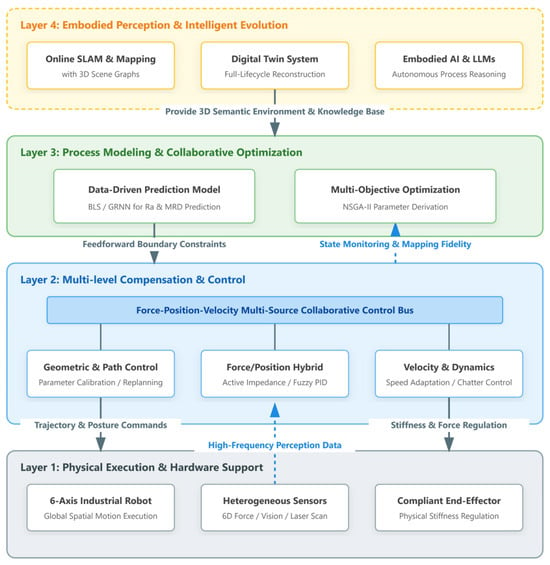
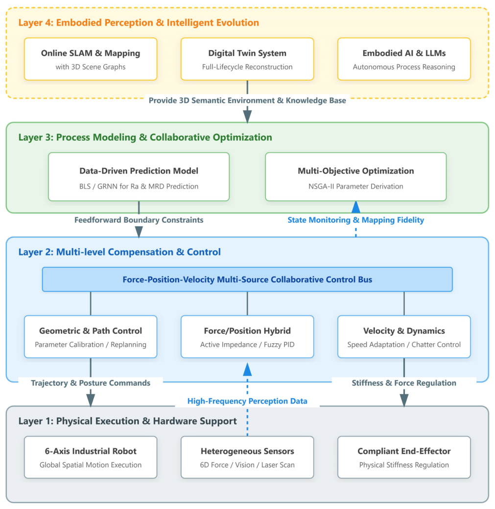
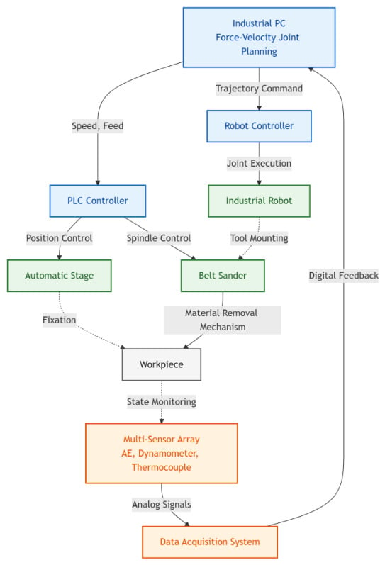
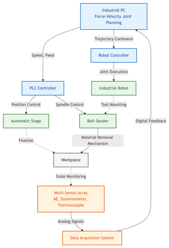
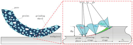
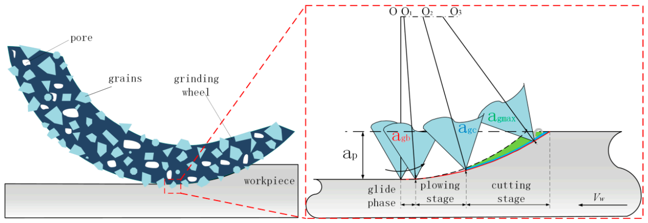
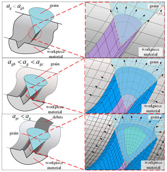
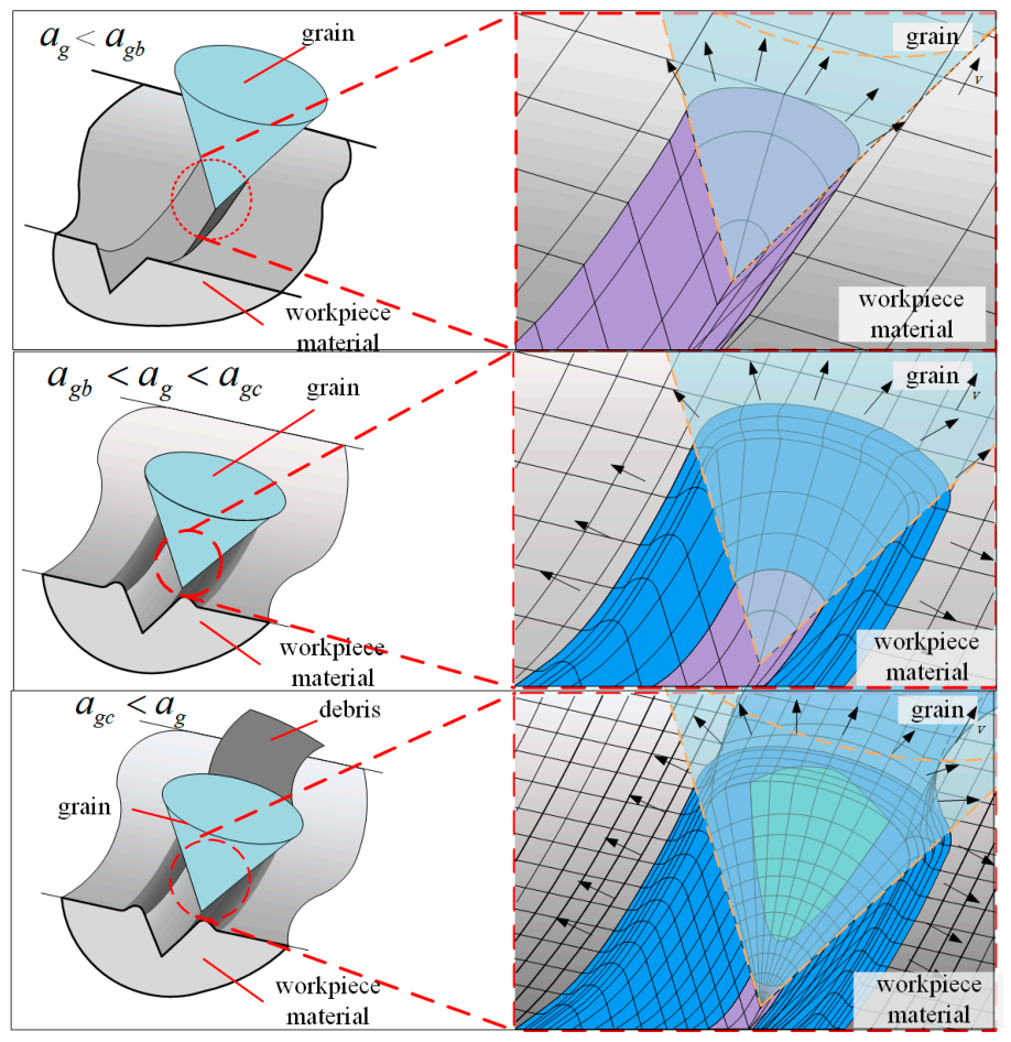
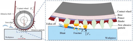
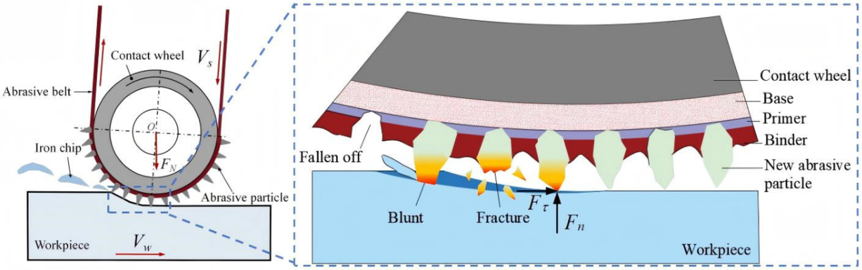
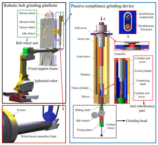
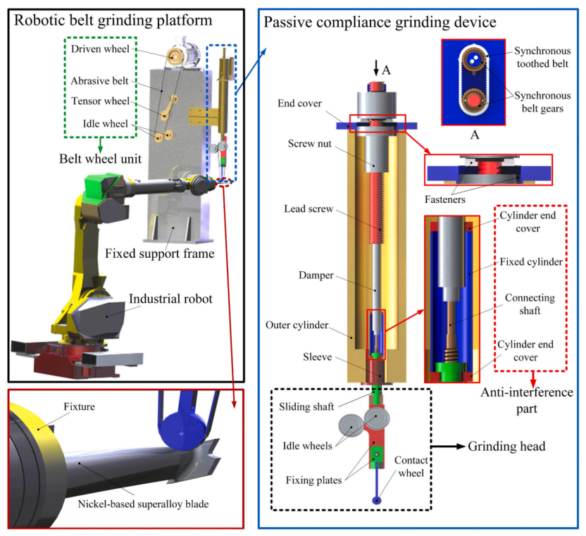
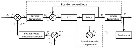
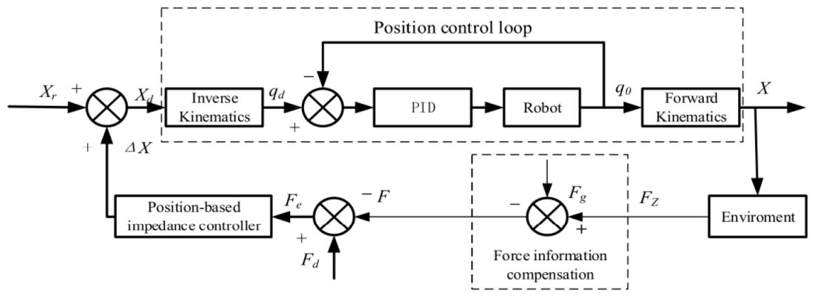
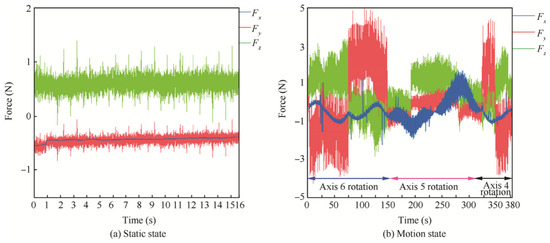
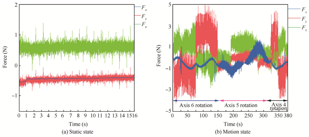
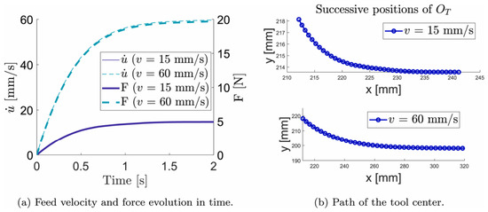
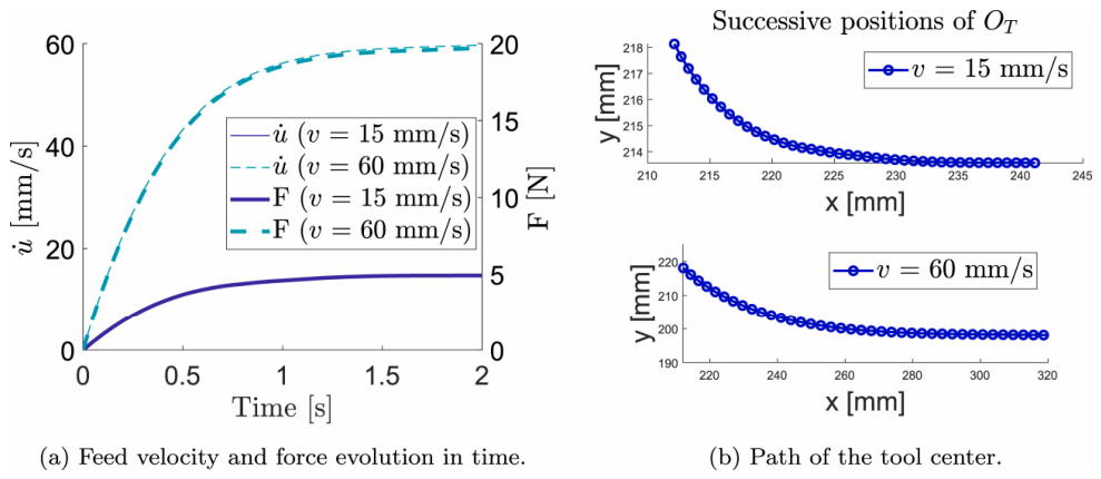


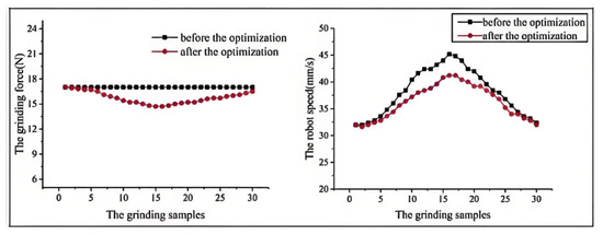
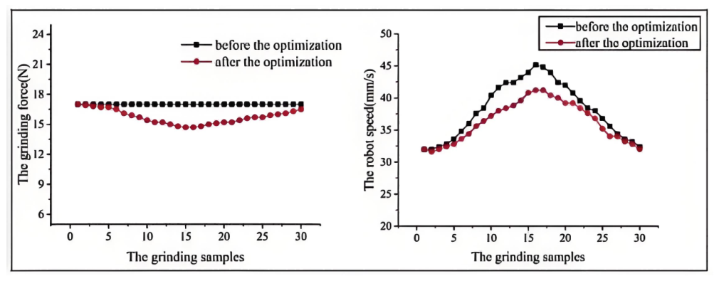
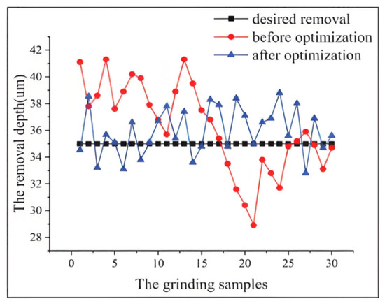
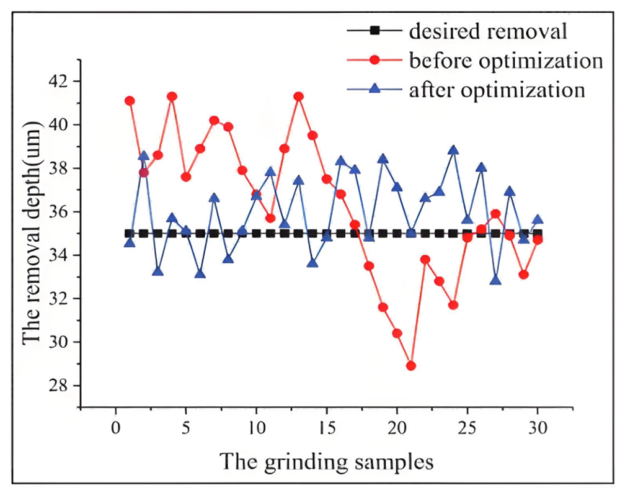
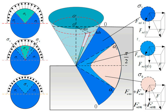
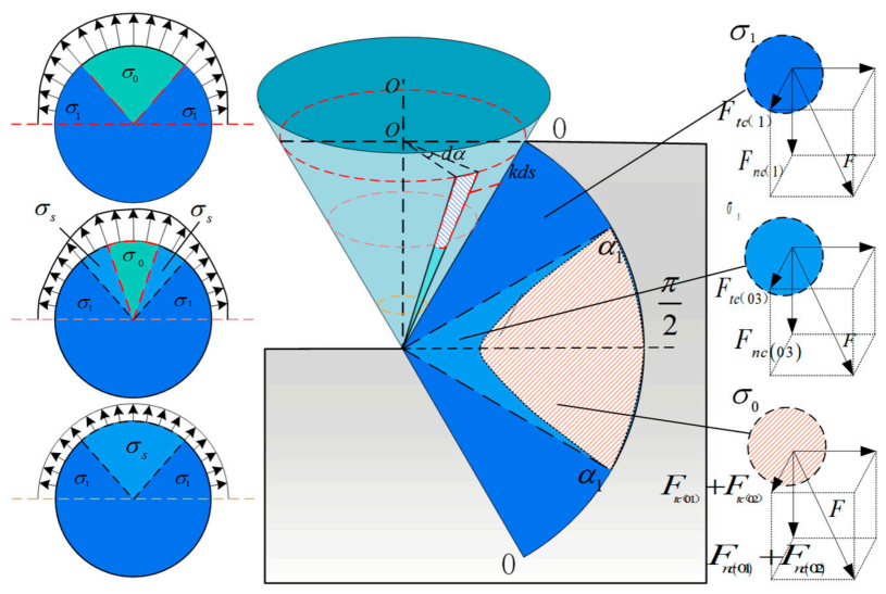
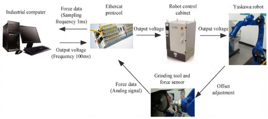
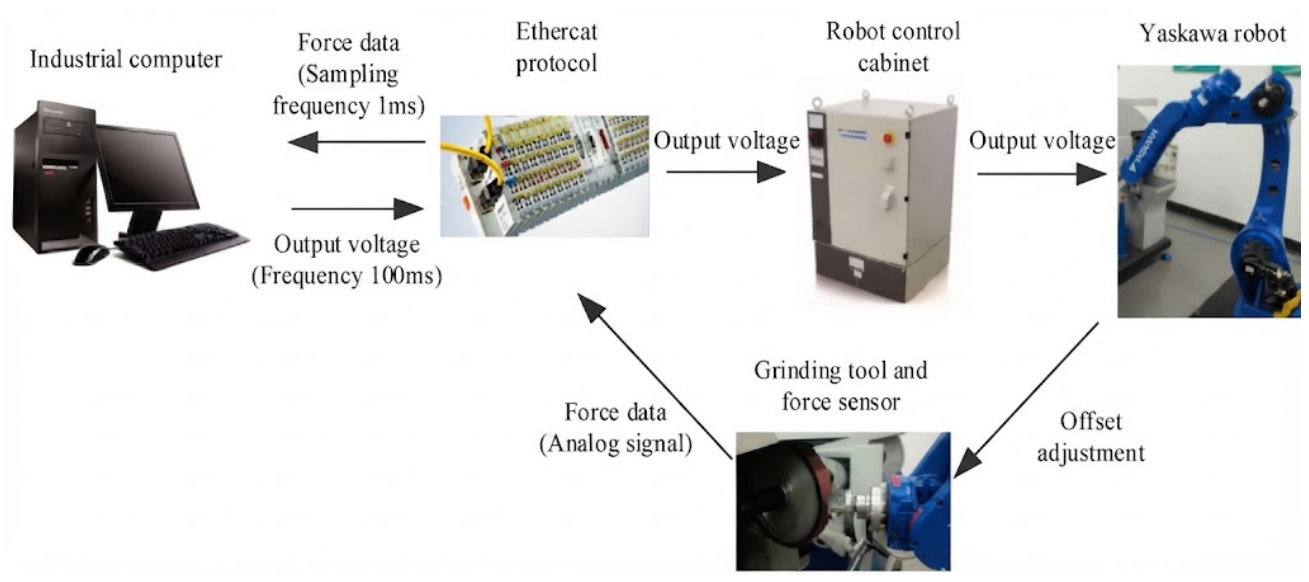
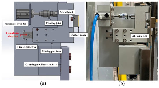
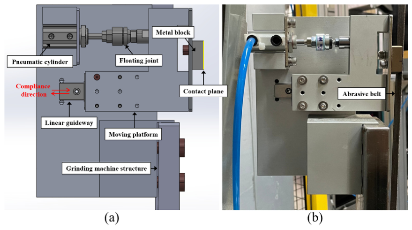
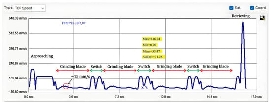
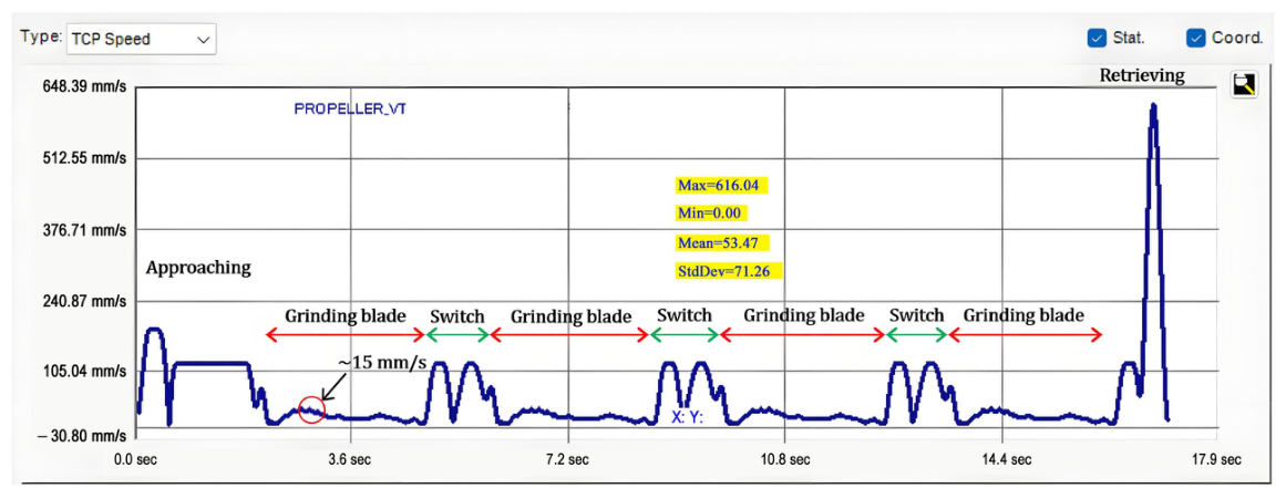
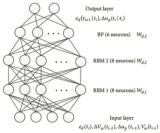
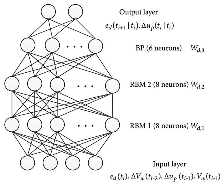
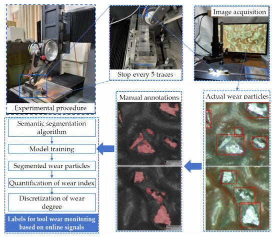
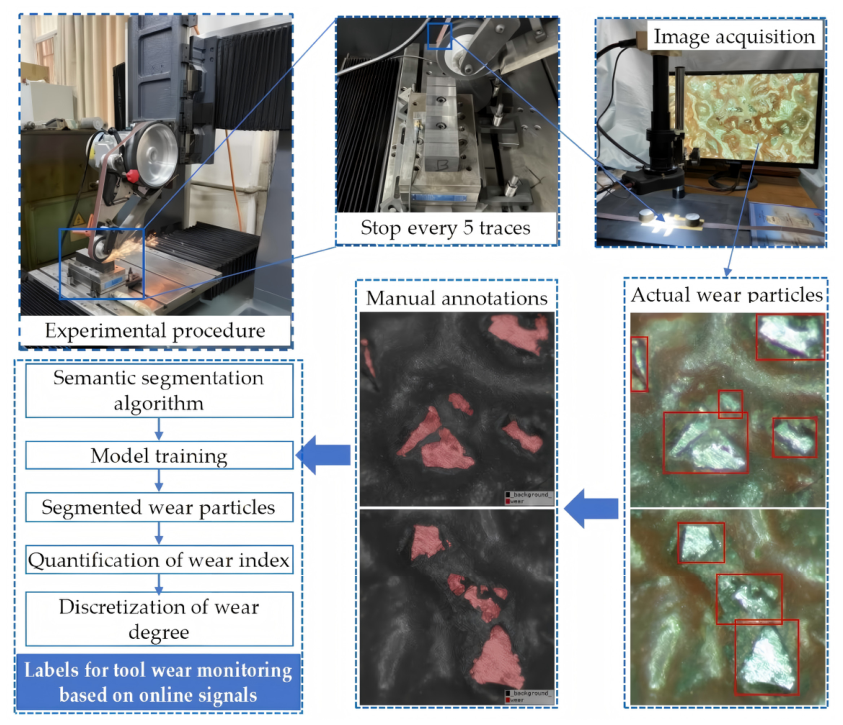
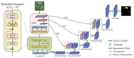
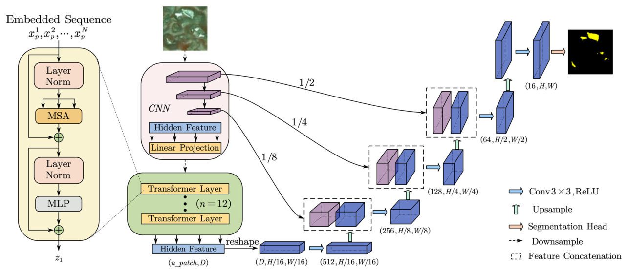
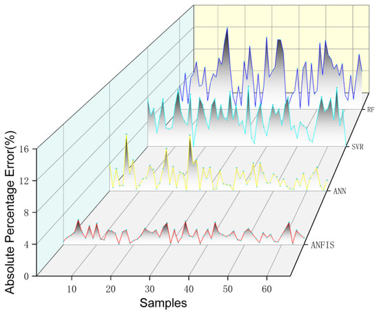
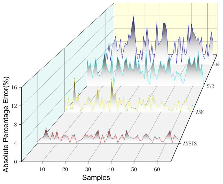

Disclaimer/Publisher’s Note: The statements, opinions and data contained in all publications are solely those of the individual author(s) and contributor(s) and not of MDPI and/or the editor(s). MDPI and/or the editor(s) disclaim responsibility for any injury to people or property resulting from any ideas, methods, instructions or products referred to in the content. |
© 2026 by the authors. Licensee MDPI, Basel, Switzerland. This article is an open access article distributed under the terms and conditions of the Creative Commons Attribution (CC BY) license.