


Abstract
This study presents an integrated technological approach for improving the service life and operational stability of a P6 die used in the cold-forging production of automotive brake connectors. The work was conducted in an industrial environment characterized by high production volumes and recurrent premature die failure. A hybrid methodology combining Shainin’s dominant-variable methodology with controlled experimentation and finite element analysis (FEA) was implemented to identify and optimize the dominant process variables affecting die durability. The attack angle, chamfer length, and machine rotational speed were determined to be the primary factors influencing stress distribution and fatigue behavior. The optimized configuration (16° attack angle, 1.4 mm chamfer length, and 88 RPM) increased die service life by 416%, improving production throughput from approximately 60,000 to over 250,000 parts per cycle. Numerical simulations confirmed that the geometric redesign effectively reduced localized Von Mises stress concentrations, contributing to enhanced structural reliability. The results demonstrate that integrating empirical industrial methodologies with numerical modeling provides a practical and replicable framework for technological improvement in high-volume cold-forging operations. The proposed approach is transferable to similar tooling optimization challenges in the automotive manufacturing sector.
1. Introduction
The automotive industry continues to evolve toward higher efficiency, safety, and manufacturing precision. Within this context, brake hose connectors are safety-critical components that ensure the integrity of hydraulic braking systems by transmitting high-pressure fluid forces. Their dimensional accuracy and structural reliability directly influence vehicle performance and operational safety.
The present study was conducted in an automotive manufacturing facility located in northern Guanajuato, Mexico, dedicated to the production of high-precision forged components for braking and steering systems, including nozzles, screws, and threaded plugs. With more than eighty years of industrial experience, the company has consolidated advanced forming technologies—particularly cold forging—within a high-volume production environment.
Cold forging is a metal forming process in which plastic deformation occurs at room temperature, allowing the material to retain its mechanical properties and tensile strength [1]. Compared with hot forging, it offers superior dimensional accuracy, improved surface finish, and enhanced mechanical strength due to strain hardening effects [2,3]. These characteristics make cold forging especially suitable for the mass production of safety-critical automotive components requiring high repeatability and mechanical reliability. The process is typically performed using high-speed mechanical or hydraulic presses equipped with multi-stage dies that enable continuous and automated production cycles [4]. For instance, a multi-stage cold forging approach applied to input shafts demonstrated measurable improvements in mechanical performance in automotive components [5].
Recent research further supports the technological relevance of cold forging in advanced automotive applications. Optimized heat treatments combined with cold forging have been shown to preserve microstructure and mechanical properties in high-strength steels [6]. Comparative analyses of manufacturing routes for automotive joints indicate that cold forging achieves superior mechanical performance and higher production yield compared with friction welding and hybrid techniques [7]. Additionally, the integration of automation and robotic systems in high-precision cold forging lines has been validated through numerical modeling, enabling optimized die geometries, reduced forming forces, and tighter dimensional tolerances. Studies on thin-walled high-performance alloys have also confirmed the feasibility of cold forging for complex geometries while maintaining controlled quality standards [8].
Nevertheless, despite these advancements, tool durability remains a critical technological challenge. Dies in forging operations are subjected to severe cyclic loading, high contact pressures, and frictional heat generation, which lead to progressive wear, fatigue damage, and, in some cases, catastrophic failure [9]. Typical failure mechanisms include overstressing, abrasive wear, adhesive wear (galling), and fatigue cracking under repeated loading cycles [9]. Tool degradation not only increases operational costs due to downtime and replacement, but also compromises dimensional precision and surface quality of forged components [10]. In automotive cold forging environments, die life is therefore a decisive factor in overall competitiveness and cost efficiency [11].
Recent developments highlight the importance of integrating monitoring technologies into die life management strategies. The real-time measurement of forming loads and stress signatures has demonstrated significant improvements in life-prediction accuracy. For example, Tchasse and Liewald [12] implemented a piezoelectric-sensor-based monitoring system that reduced die life prediction error from ± 20% to ± 7%. These findings suggest that effective die-life optimization depends not only on material selection and geometry design, but also on operational data integration and predictive maintenance strategies [12,13].
Within this industrial framework, premature wear and recurrent fracture of the P6 die used in the production of part no. 310PE were identified as critical issues. The die operates under severe mechanical conditions due to the component’s complex geometry and high production volume, which reaches approximately one million units per month. Historical production records over the past three years reveal repeated failures and a progressive reduction in service life, resulting in unplanned downtime and increased tooling costs. These operational constraints highlight the necessity of a systematic and technologically grounded approach to identify root causes and implement corrective design and process modifications.
The P6 die corresponds to a critical forming stage within the multi-station cold forging sequence, where the final geometry of the brake connector is partially defined through a combined extrusion and calibration operation. At this stage, the material undergoes severe plastic deformation under high contact pressures and constrained flow conditions, resulting in significant stress concentration at the die cavity transitions.
Unlike upstream forming stages, where deformation is more gradual, the P6 die is subjected to intensified compressive and shear stresses due to the near-final shaping of the component and the reduced material flow freedom. This operational condition makes the P6 die particularly susceptible to fatigue crack initiation and premature fracture. Consequently, its performance plays a decisive role in the overall stability and productivity of the forging process.
Despite the significant body of research on cold-forging die performance, most studies focus on one of material selection, surface treatments, or purely numerical optimization strategies. In many industrial environments, however, tool failure arises from the combined influence of geometric discontinuities, operational parameters, and real production variability. Existing approaches often rely on complex statistical models or fully numerical simulations that are difficult to implement in high-volume manufacturing lines. Consequently, there remains a need for practical methodologies capable of integrating empirical industrial knowledge with physics-based validation in order to identify dominant variables governing die durability.
In this context, the present research proposes an integrated technological framework combining Shainin’s dominant-variable methodology with controlled industrial experimentation and finite element analysis (FEA). Unlike traditional approaches that rely solely on statistical DOE or purely numerical modelling, the proposed strategy emphasizes rapid identification of dominant variables directly under industrial production conditions and validates the results through structural simulation. This combined empirical–computational approach enables practical optimization of die geometry and operational parameters while maintaining industrial feasibility.
2. Materials and Methods
The present study aimed to identify and mitigate the root causes of premature fracture in the P6 die used in the cold forging production of part number 310PE. A structured and technology-oriented methodological framework was implemented, integrating Dorian Shainin’s process-improvement philosophy with controlled industrial experimentation and finite element numerical simulation (FEA). This hybrid strategy enabled systematic identification of dominant process variables and structural validation of proposed design modifications through computational modelling.
The research was structured into five sequential phases:
- (1)
- Diagnostic and causal analysis;
- (2)
- Experimental design and measurement validation;
- (3)
- Multi-Vari statistical assessment;
- (4)
- Finite element structural validation;
- (5)
- Integration of experimental and numerical findings.
The methodological logic follows Shainin’s dominant-variable strategy for advanced manufacturing systems [14], which prioritizes isolating the most influential factor responsible for process variation rather than exploring high-order statistical interactions.
2.1. Phase 1: Diagnostic and Causal Analysis
The initial phase consisted of compiling historical operational data related to the P6 die over a three-year production period. Records included tooling consumption rate, number of parts per cycle, fracture frequency, maintenance interventions, and downtime events.
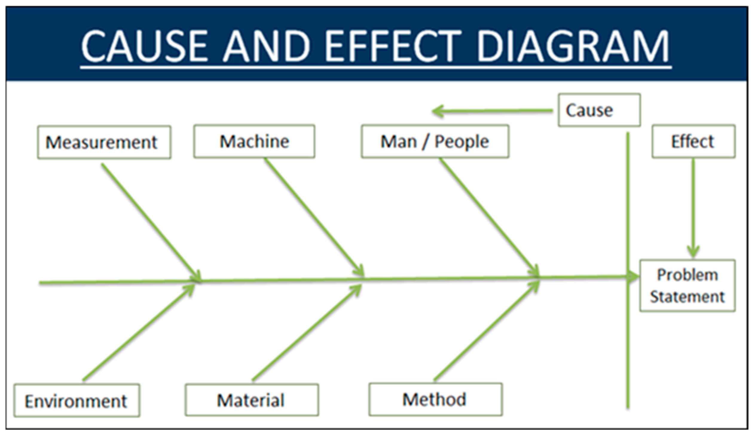
A structured cross-functional session involving production, engineering, and maintenance personnel was conducted to identify potential failure drivers. The results were organized using an affinity table and subsequently represented in an Ishikawa (cause-and-effect) diagram (Figure 1), grouping potential causes into material, method, machine, environment, and manpower categories, following classical quality engineering approaches [14].
Figure 1.
Cause-and-effect diagram.
This diagnostic stage enabled the systematic identification of candidate variables affecting die durability and established the foundation for controlled experimentation.
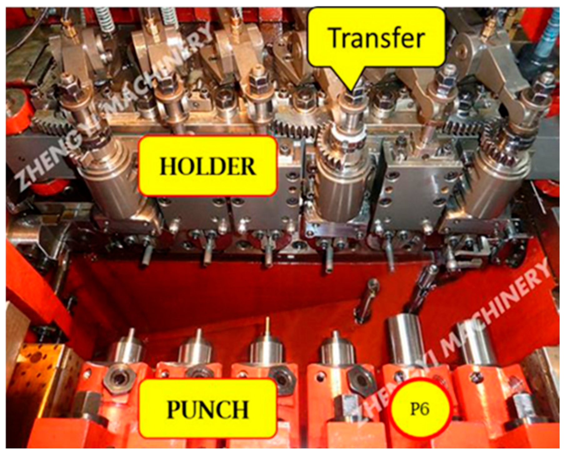
The industrial forming system used in this study corresponds to a multi-stage cold-forging press (BP730), whose configuration is shown in Figure 2. The system operates under high-frequency cycles with multiple forming stations, generating severe contact conditions between the die and the workpiece. These operational characteristics are critical for understanding the mechanical loading conditions and stress environment to which the P6 die is subjected during production.
Figure 2.
Main components of the forming machine (BP730 press).
2.2. Phase 2: Experimental Design and Measurement System
To quantify the influence of the identified variables on die service life, a fractional factorial experimental design was implemented. This approach allows the evaluation of main effects and selected interactions while maintaining practical feasibility within an industrial production environment [15]. Factor levels were defined based on operational experience, machine constraints, and preliminary empirical trials, ensuring that all tested combinations remained within safe production limits [16].
Geometric measurements were conducted using a high-precision Mitutoyo Formtracer Avant FTA-D3000 hybrid profilometer, calibrated in accordance with ISO 5436-1:2000. The system operates with a Z1-axis resolution of 0.1 nm (0.0001 µm) and an X-axis drive accuracy of ±(0.8 + 0.01 L) µm, providing the high sensitivity required for sub-micron characterization. Measurements were performed using a 2 µm radius diamond stylus with a controlled force of 0.75 mN, enabling the acquisition of high-fidelity surface profiles and digital traceability of dimensional variations across production batches [17]. An automated acquisition interface via FORMTRACEPAK software (version 5.2) was used to store data, ensuring repeatability and traceability—key requirements in industrial process validation [18]. Prior to executing the factorial design, preliminary screening trials using a one-factor-at-a-time (OFAT) approach were conducted to evaluate system sensitivity and define operational bounds. Although OFAT methods are limited in capturing factor interactions, they are useful in early-stage experimentation to establish feasible parameter ranges prior to applying more robust factorial designs [19].
2.3. Phase 3: Multi-Vari Analysis and Selection of Critical Parameters
Multi-Vari charts were applied to determine dispersion patterns within and between factor levels, following Shainin’s practical industrial methodology [14]. Unlike classical ANOVA-based inference, this approach emphasizes graphical identification of dominant variables under real production variability conditions.
The analysis was performed using Minitab 17 software under three experimental arrangements (A, B, and C), in which factor sequencing was modified to evaluate robustness of the observed trends.
Evaluation criteria included the following:
- (a)
- Within-group dispersion;
- (b)
- Between-group variation;
- (c)
- Process stability trends;
- (d)
- Consistency of die service life.
This graphical–statistical assessment enabled the isolation of parameter combinations associated with minimal variability and extended die life. The resulting optimized levels were then selected for structural validation via numerical simulation [15]. Such industrially oriented statistical strategies have been reported as effective in high-volume forming operations where rapid decision-making is required [20].
2.4. Phase 4: Numerical Validation Through Finite Element Analysis (FEA)
To evaluate the structural implications of geometric modifications, a finite element model was developed under linear-static, plane-stress conditions.
The numerical environment was custom-developed for this applied research study, avoiding dependence on commercial software and ensuring the full transparency of model assumptions and boundary conditions.
Although cold forging inherently involves highly non-linear material flow, a linear-elastic formulation was adopted for the die analysis. This assumption is justified by the fact that tool steels are specifically designed to operate within the elastic regime, thereby avoiding permanent deformation and premature yielding. The non-linear effects of the process were incorporated indirectly through the application of a peak contact pressure of 1800 MPa, which represents the maximum forging load and falls within the typical range reported for cold forging of high-strength steels (1500–2000 MPa) [21]. This modeling strategy enables a reliable identification of critical stress concentration regions, which are widely recognized as the primary drivers of fatigue-induced fracture in forging dies.
The omission of plastic deformation and non-linear contact behavior constitutes an additional modeling simplification that must be addressed. In the present study, plasticity of the die material was not considered because the tool steel is specifically designed to operate below its yield strength under nominal working conditions. Therefore, fatigue failure is primarily driven by cyclic elastic stress concentration rather than bulk plastic deformation.
Similarly, non-linear contact effects between the workpiece and the die were not explicitly modeled using full contact algorithms. Instead, their mechanical influence was incorporated through an equivalent uniform pressure load combined with a simplified friction representation using a constant Coulomb coefficient (μ = 0.1), representative of lubricated cold-forging conditions. This approach captures the dominant loading mechanisms while avoiding the numerical complexity associated with fully non-linear contact formulations.
Although these simplifications may affect the accuracy of absolute stress values, they do not compromise the comparative nature of the analysis. The objective of the model is to evaluate relative stress redistribution between design configurations rather than to reproduce the full thermo-mechanical response of the forging process. Consequently, the adopted formulation provides a computationally efficient and physically consistent framework for identifying critical stress regions and assessing design improvements under realistic industrial constraints. The model’s predictive accuracy was qualitatively validated through correlation with experimentally observed fracture location.
2.4.1. Finite Element Model Formulation
To ensure reproducibility and methodological rigor, the finite element model was formulated based on the governing equations of linear elasticity under plane-stress conditions, following classical continuum mechanics and finite element theory [22].
The equilibrium equation is defined as
where σ is the Cauchy stress tensor and b represents body forces, which were neglected in this study. The constitutive behavior of the tool steel was modeled using Hooke’s law for isotropic materials:
where D is the elasticity matrix for plane-stress conditions:
The discretized finite element system leads to the global equation
where K is the global stiffness matrix and F is the external force vector derived from the applied pressure load. The equivalent Von Mises stress was used as the failure indicator, as it is widely adopted for ductile materials under multiaxial stress states [23].
2.4.2. Geometry, Discretization, and Boundary Conditions
The numerical simulations were conducted under linear elastic conditions using a two-dimensional plane-stress formulation, which is suitable for representing stress states in thin die sections subjected predominantly to in-plane loading during cold-forging operations. Similar modeling approaches have been successfully applied in the analysis of stress concentration and fatigue behavior in forging tools subjected to cyclic compressive loading [24].
Although the real die geometry is inherently three-dimensional, the adoption of a two-dimensional plane-stress model represents a controlled simplification aimed at isolating the dominant stress concentration mechanisms governing fatigue initiation. The selected cross-sectional representation corresponds to the most critical region of the die, where failure is consistently observed under industrial conditions.
This modeling approach assumes uniform stress distribution along the out-of-plane direction and neglects secondary effects such as axial gradients, non-uniform contact conditions, and three-dimensional constraint variations. However, in high-stiffness tooling systems subjected predominantly to compressive loading, the primary stress drivers are governed by in-plane stress concentration at geometric discontinuities.
Consequently, the two-dimensional formulation provides a reliable approximation for comparative analysis between design configurations, particularly for evaluating relative reductions in peak Von Mises stress and identifying critical locations for crack initiation. Nevertheless, it is acknowledged that absolute stress magnitudes may differ from those obtained using a full three-dimensional model. Despite this limitation, the strong correlation observed between simulated stress concentration zones and experimentally identified fracture locations supports the validity of the adopted approach for engineering decision-making.
The baseline die geometry was represented as a 40 × 30 mm rectangular domain with a central circular cavity simulating the stress-concentration region. A structured quadrilateral mesh with medium density was applied, refined along the cavity boundary to capture stress gradients.
Boundary conditions included the following:
- (a)
- Fully constrained lower surface (fixed support);
- (b)
- Uniform distributed load applied on the central upper surface equivalent to forging pressure.
Material properties corresponded to tool steel with the following properties:
- (a)
- Elastic modulus: 210 GPa;
- (b)
- Poisson’s ratio: 0.30.
Two redesign proposals were evaluated:
- (a)
- Proposal A: Increased cavity radius (6.5 mm) and thickness (1.1 mm);
- (b)
- Proposal B: The same geometric adjustments with modified elastic modulus (270 GPa) and reduced Poisson ratio (0.28), representing an increase in effective local stiffness achievable through engineering solutions such as the use of higher-stiffness tool steels, surface treatments, or the incorporation of reinforced inserts in critical regions of the die.
Von Mises equivalent stress was selected as the evaluation criterion due to its established relevance in predicting yielding and fatigue initiation in ductile metallic tooling [25].
Comparative stress-field analysis was conducted across the baseline and modified configurations to assess peak stress redistribution and reduction potential. The model’s predictive accuracy was qualitatively validated through correlation with experimentally observed fracture locations.
2.5. Phase 5: Integration of Experimental and Numerical Results
The final phase consisted of correlating experimentally optimized process parameters with numerical stress-distribution outcomes.
Die service life improvements observed in production trials were compared against reductions in peak Von Mises stress obtained through FEA. This integrative approach provided mechanistic validation of the empirical findings and strengthened the reliability of the proposed technological intervention.
The combined framework—integrating Shainin-based dominant-variable identification, controlled industrial experimentation, and structural numerical modelling—constitutes a reproducible methodology for tooling optimization in automotive cold-forging systems.
3. Results
3.1. Problem Analysis
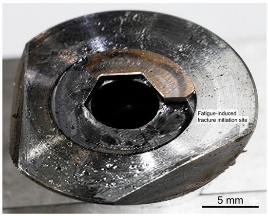
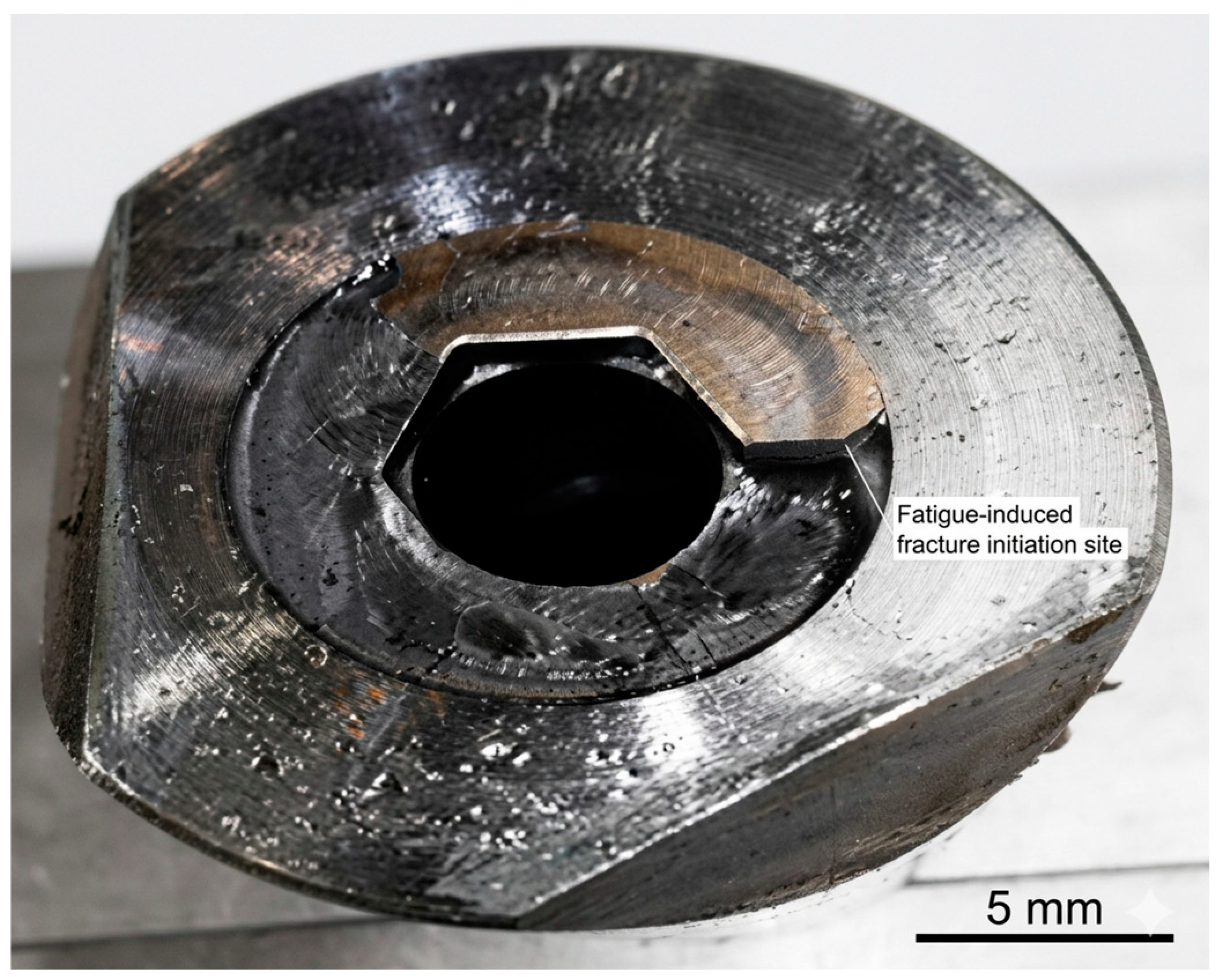
Application of the Dorian Shainin methodology confirmed the recurrent structural failure of the P6 die used in the production of component 310PE. These failures had a direct negative impact on production continuity and tooling costs (Figure 3).
Figure 3.
Fracture of the P6 die.
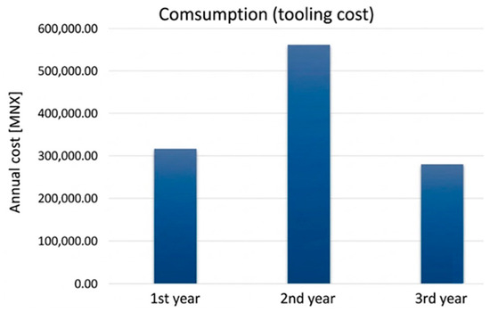
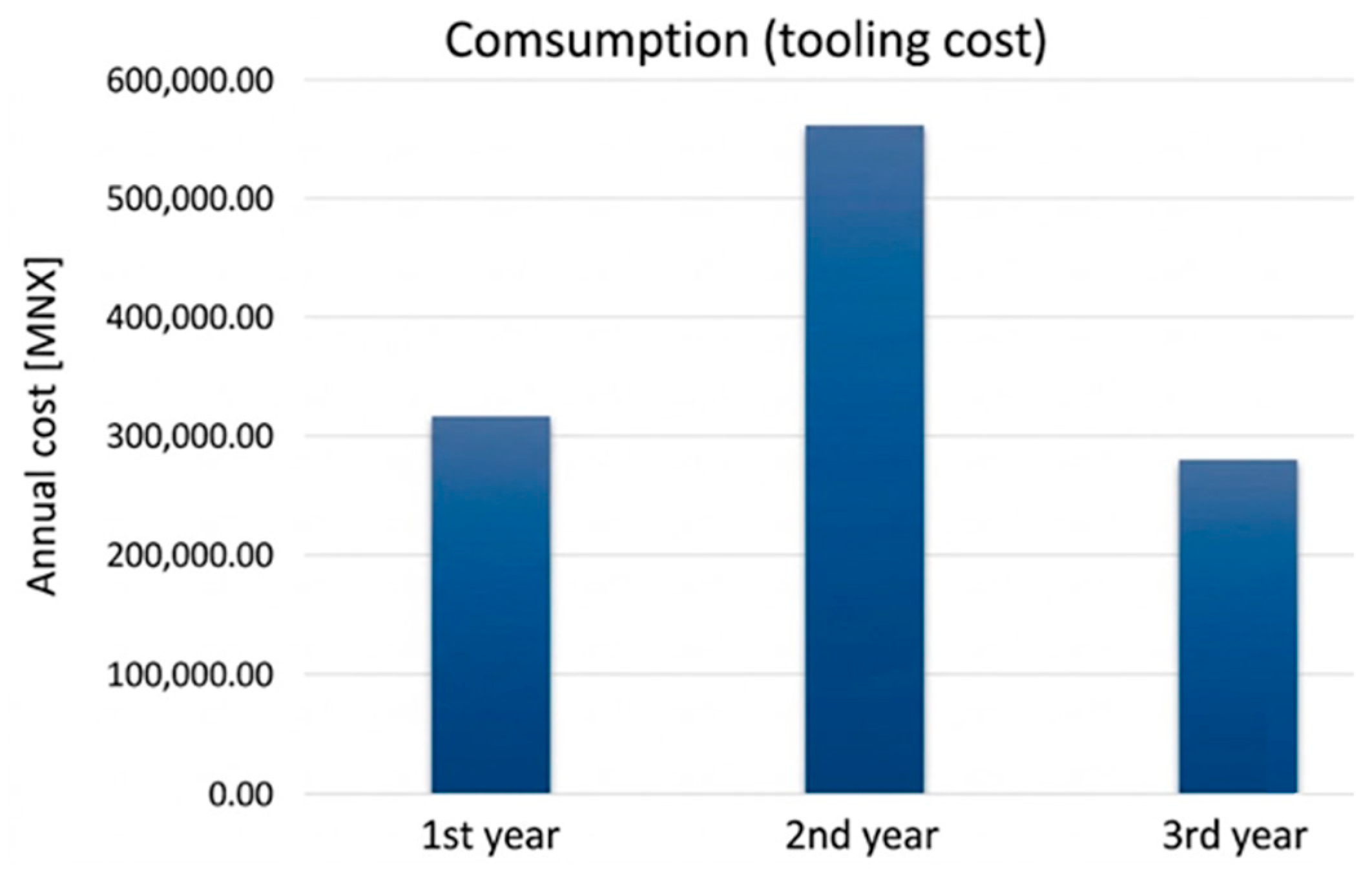
Tooling consumption increased by 43% during the first two years and exhibited a marked upward trend during the initial months of the third year (Figure 4), indicating a progressive deterioration of die performance and increasing operational instability. Similar trends have been reported in industrial cold-forging environments, where progressive wear, fatigue damage, and stress concentration lead to accelerated tool degradation and rising tooling costs during prolonged production cycles [26].
Figure 4.
Annual production costs.
3.2. Clue Generation and Analysis of Potential Causes
The brainstorming session, affinity table, and Ishikawa diagram (Figure 1) enabled the systematic classification of potential failure drivers into material, method, machine, environment, and manpower categories, following Shainin’s dominant-variable strategy [15].
From this structured analysis, three primary controllable variables were identified:
- (a)
- Attack angle;
- (b)
- Chamfer length;
- (c)
- Machine rotational speed (RPM).
These factors directly influence material flow, local stress distribution, and fatigue accumulation per cycle. Their selection aligns with studies on multiaxial stress states in cold-forging tools, which highlight the interaction of axial compression and shear stresses during crack initiation.
3.3. Measurement Strategy and Operating Conditions
To reduce the influence of non-controllable factors (temperature, humidity), a batch-based experimental structure was implemented.
The FTA-D3000 profilometer ensured high-resolution measurement of geometric variables, strengthening response reliability (die life). This measurement rigor aligns with established die-optimization methodologies based on integrated CAD/FEA frameworks [27,28], ensuring that physical metrology data accurately informs the numerical validation process.
Preliminary OFAT trials revealed that die life was influenced by interactions among the selected variables. Although direct trends were observable (Figure 5), isolated factor modification did not fully explain variability.
Figure 5.
Influence of attack angle factor.
The parameter ranges defined in Table 1 were established from these screening trials.
Table 1.
Ranges and levels of primary factors.
The strong interdependence observed among parameters supports the literature warnings against analyzing die design variables in isolation [29,30].
3.4. Multi-Vari Analysis and Process Stabilization
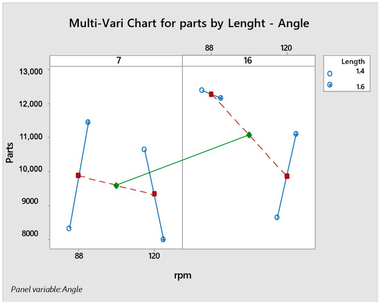
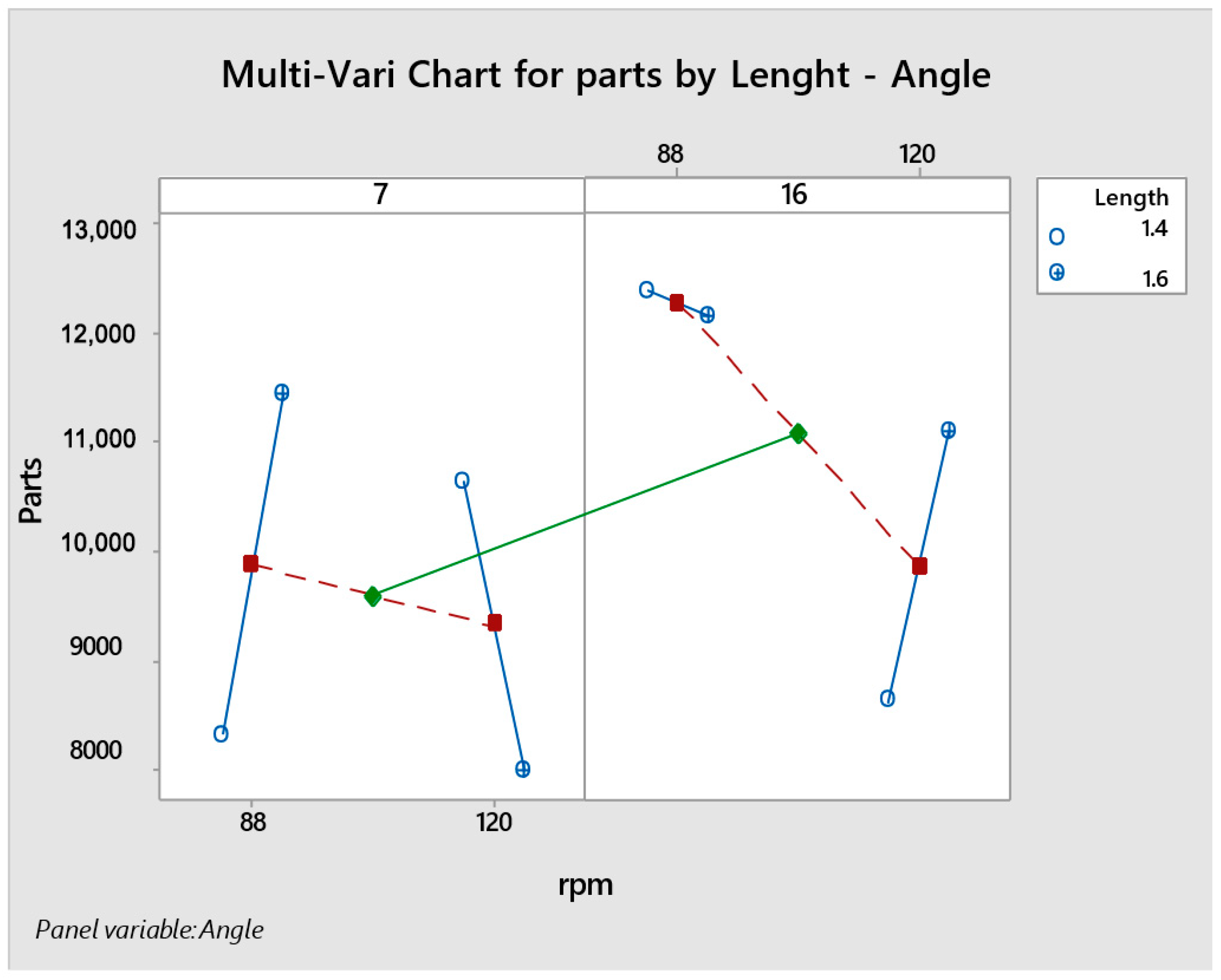
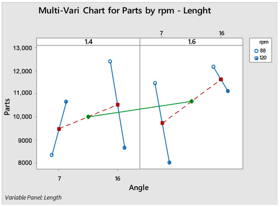
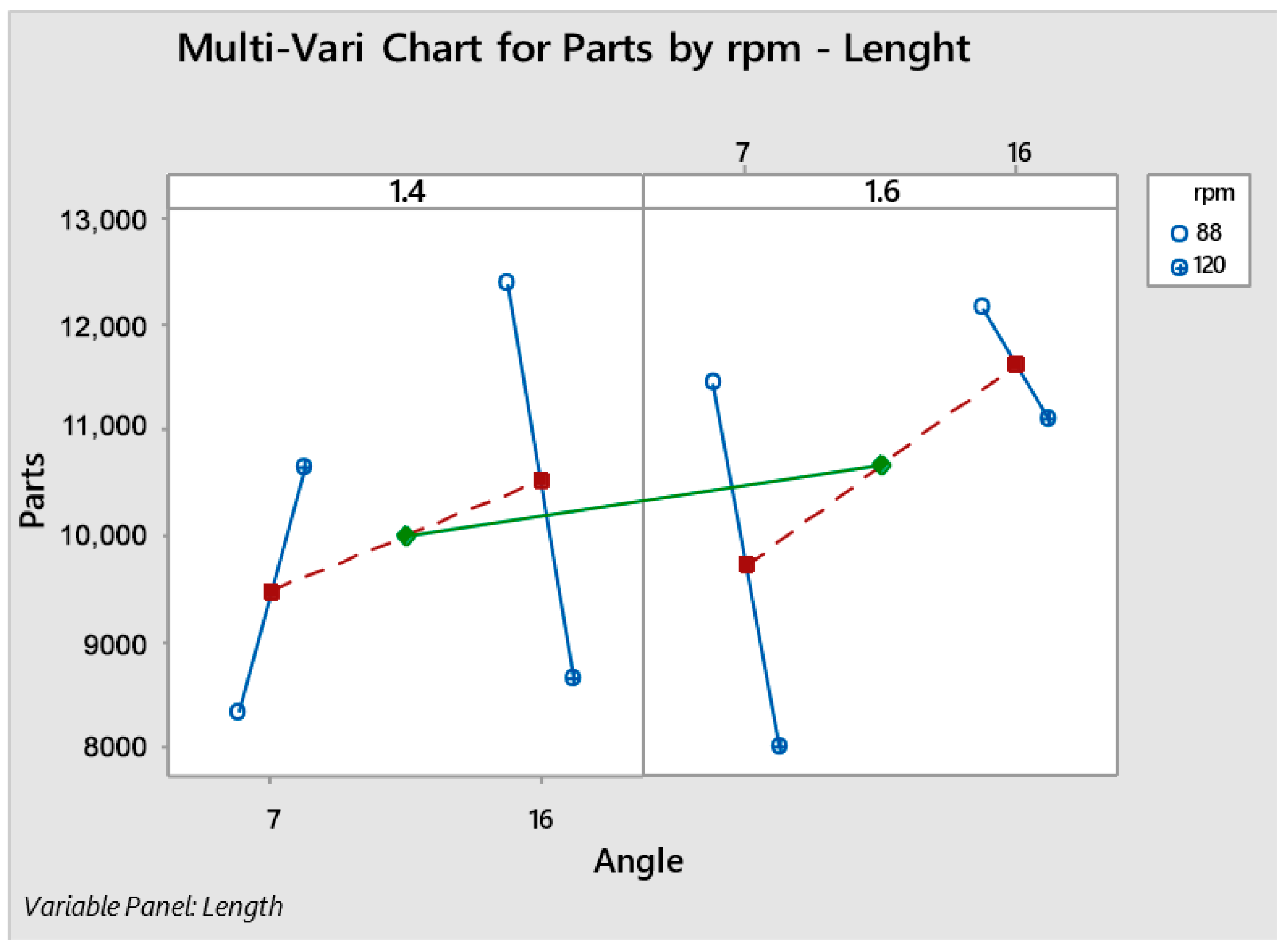
In the Multi-Vari charts (Figure 6, Figure 7 and Figure 8), the red dashed lines represent within-group variation, reflecting local dispersion under the same factor combination, while the green solid lines indicate the group mean trend, representing the central tendency of each experimental condition. The reduction in the amplitude of the red dashed lines and the progressive alignment of the green solid lines indicate a decrease in process variability and improved stability.
Figure 6.
Multi-Vari chart organized by Arrangement A: Angle—Length—RPM. Red dashed lines represent within-group variation, while green solid lines indicate the group mean trend.
Figure 7.
Multi-Vari chart organized by Arrangement B: Length—RPM—Angle. Red dashed lines represent within-group variation, while green solid lines indicate the group mean trend.
Figure 8.
Multi-Vari chart organized by Arrangement C: RPM—Angle—Length. Red dashed lines represent within-group variation, while green solid lines indicate the group mean trend.
Arrangement B: Dispersion was reduced after adjustments in pressure and thermal conditions alongside primary factors.
Arrangement C: The lowest variability was achieved, defining the optimal combination: (angle = 16°, length = 1.4 mm, RPM = 88).
Under these optimized conditions, die service life exhibited a significant breakthrough, increasing from a baseline of 60,000 parts to a stable average of 250,000 parts per cycle. This represents a 416% improvement in tooling durability, effectively stabilizing the production process.
This progressive stabilization confirms Shainin’s hypothesis of narrowing the cause set through sequential orientation. These findings are supported by reviews emphasizing uniform material flow and reduced peak loading as key to crack-risk minimization [31].
3.5. Comparative Performance Validation (Six-Pack Test)
The comparative validation between the current (C) and proposed (B) conditions (Table 2) demonstrated a substantial performance increase.
Table 2.
Comparison between current (C) and proposed (B) parameters.
The Multi-Vari analysis provided a visual and statistical confirmation of the process stabilization. In Figure 6 (Arrangement A), the vertical lines show high ‘within-group’ variation, indicating that the initial combination of factors was unable to control the stress cycles. As the sequencing was refined, Figure 8 (Arrangement C) revealed a significant convergence of the data points. The reduction in the length of the vertical bars and the alignment of the means in Arrangement C demonstrate that the 16° attack angle combined with 88 RPM effectively minimized the process noise. This convergence identifies these parameters as the ‘Red X’ (dominant variables) responsible for the transition from a high-failure regime (60,000 parts) to a stable high-performance state (250,000 parts), as the geometric changes successfully redistributed the cyclic mechanical loads, as shown in Figure 9. These findings are supported by reviews emphasizing uniform material flow and reduced peak loading as key to crack-risk minimization [31].
Figure 9.
Evaluation of the current and proposed processes. Letters (B and C) represent factor arrangements: B (intermediate) and C (optimized with reduced variability).
This magnitude of increase demonstrates not only geometric effectiveness but also the technological relevance of process-speed management in high-volume forging systems [30].
3.6. Finite Element Simulation (FEA) and Structural Correlation
To complement the experimental findings obtained through the Shainin-based analysis and controlled production trials, a finite element model was developed to evaluate the structural behavior of the forging die and to validate the effectiveness of the proposed geometric modifications. Numerical simulation is widely used to investigate stress distribution and fatigue initiation in forging tools due to its ability to reproduce complex loading conditions and geometric discontinuities present in metal forming processes [11,32].
The computational domain represented a simplified cross-section of the die body, including the cavity region and the surrounding structural material. The baseline die geometry was modeled as a rectangular domain measuring approximately 40 × 30 mm, with a central cavity representing the critical stress-concentration zone observed during industrial operation. The geometry was discretized using a structured quadrilateral mesh composed of second-order elements, which provide improved numerical accuracy when representing stress gradients in contact-dominated forming problems.
To capture stress concentration phenomena with sufficient resolution, a local mesh refinement strategy was implemented around the cavity and transition-radius regions. The characteristic element size in these critical zones ranged between 0.05 and 0.1 mm, while a coarser mesh was applied in non-critical areas to maintain computational efficiency. This adaptive discretization ensured accurate representation of localized stress peaks while limiting the overall computational cost.
Boundary conditions were defined to reproduce the mechanical constraints experienced by the die during the forging cycle. The lower die surface was fully constrained to simulate rigid attachment to the press tooling assembly. A uniform distributed pressure load was applied on the cavity surface to represent the contact force exerted by the workpiece during forming. Based on industrial operating data and values reported in the cold-forging literature, the applied pressure was set to 1800 MPa, consistent with contact stresses reported in industrial cold-forging operations [9,29,33]. Frictional interaction between the die and workpiece interface was represented using a Coulomb friction coefficient of μ = 0.1, representative of lubricated cold-forging processes [10].
Three die configurations were analyzed in the numerical study. The baseline configuration reproduced the original die design and material properties, with an elastic modulus of 210 GPa and a Poisson’s ratio of 0.30.
Proposal A introduced geometric modifications aimed at reducing stress concentration effects, including increased cavity radii and localized adjustments to the die wall thickness.
Proposal B incorporated the same geometric improvements but additionally increased the effective structural stiffness of the die material (E = 270 GPa, ν = 0.28), representing the potential use of higher-stiffness tool materials or reinforced die inserts.
Von Mises equivalent stress was selected as the primary evaluation criterion due to its established applicability in predicting yielding and fatigue initiation in ductile metallic tooling subjected to multiaxial stress states [23].
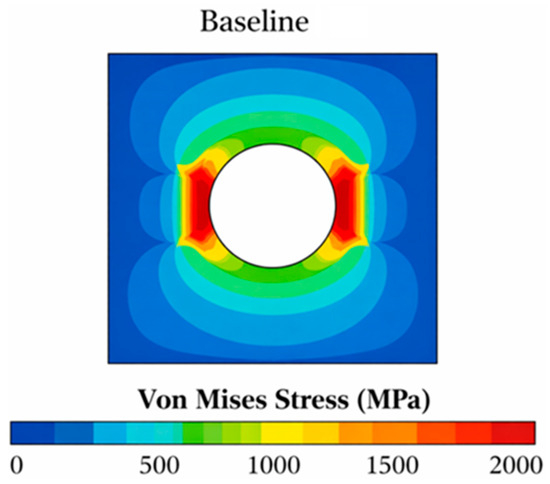
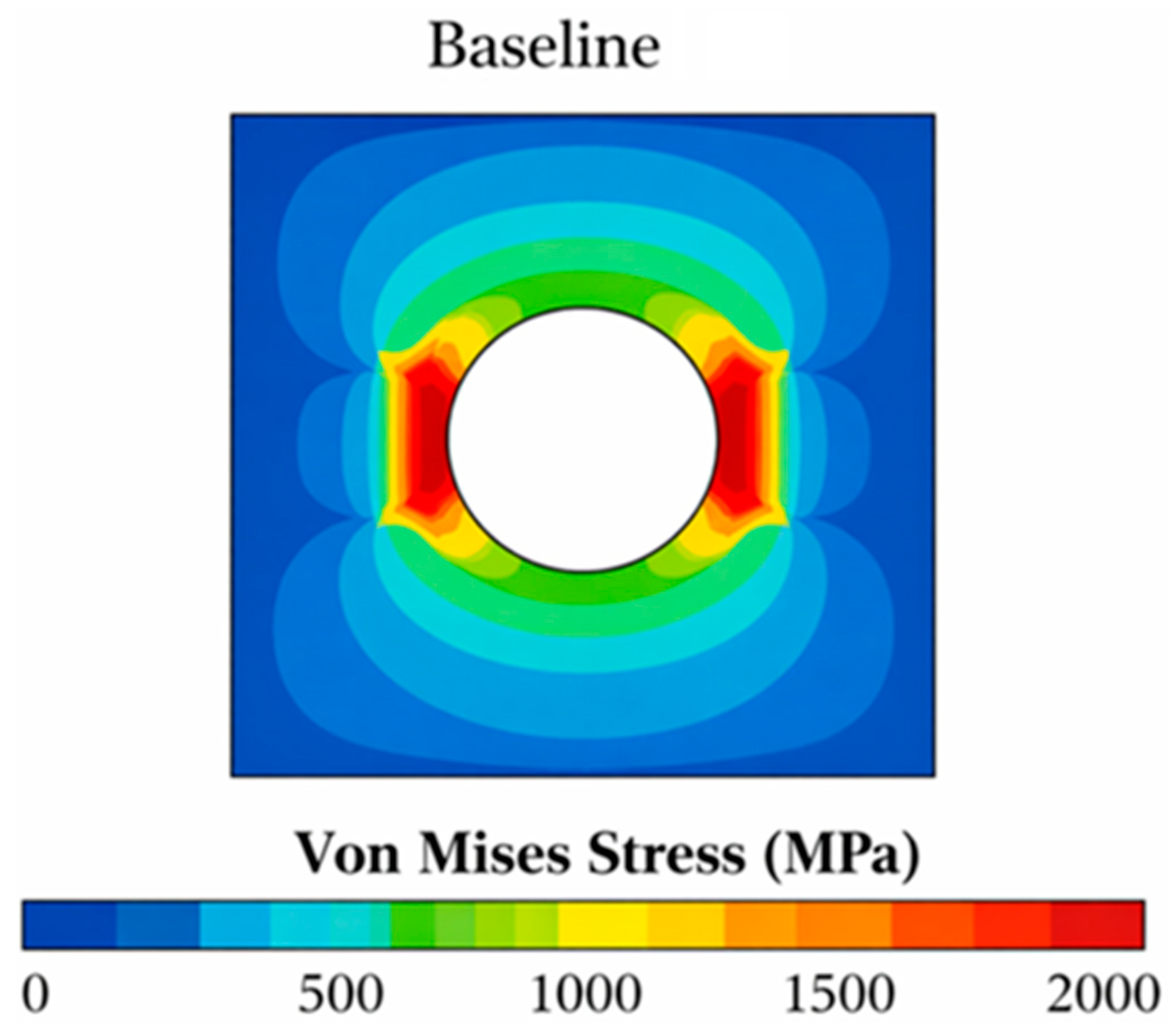
The stress distribution obtained for the baseline configuration revealed pronounced stress concentrations located at the cavity transition radius, as illustrated in Figure 10. This region corresponds to the typical crack-initiation location observed in failed P6 dies during industrial operation and reported in classical studies of cold-forging tool fatigue [9,34].
Figure 10.
Simulation of the original die (baseline condition).
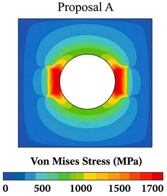
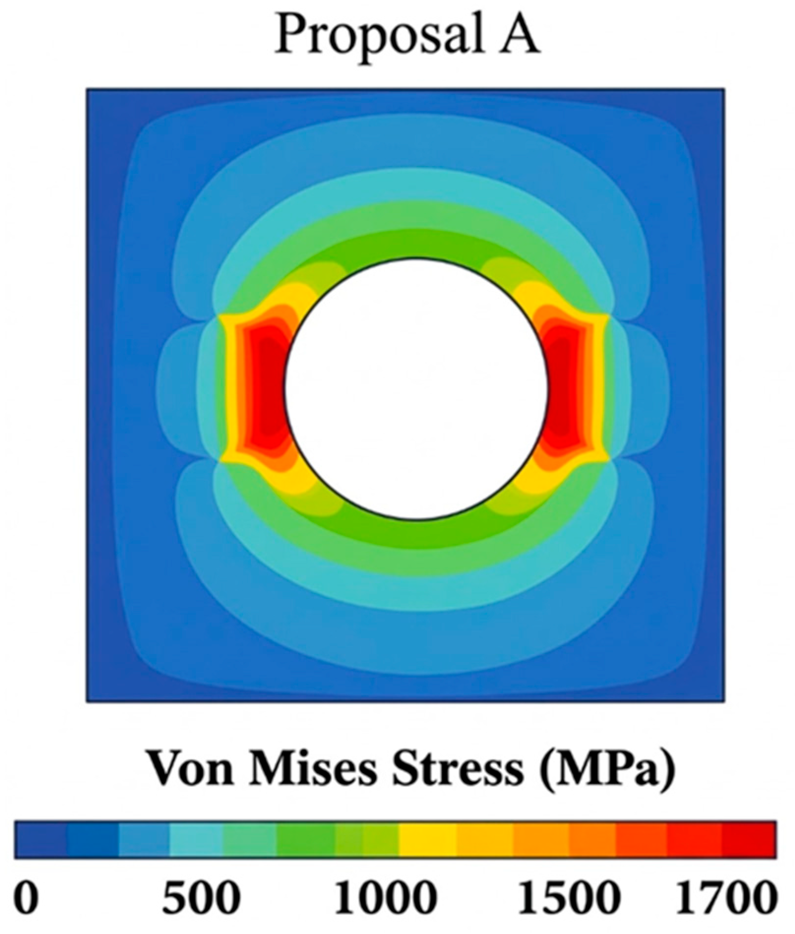
Proposal A introduced smoother geometric transitions through increased cavity radii and adjusted wall thicknesses. As shown in Figure 11, these modifications partially redistributed the stress field and reduced the magnitude of localized stress peaks. However, the highest stresses remained concentrated near the cavity transition zone, indicating that geometric modification alone was insufficient to fully mitigate the stress concentration effect.
Figure 11.
Simulation of the die with adjusted radii and thicknesses (Proposal A).
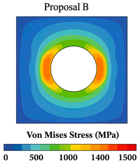
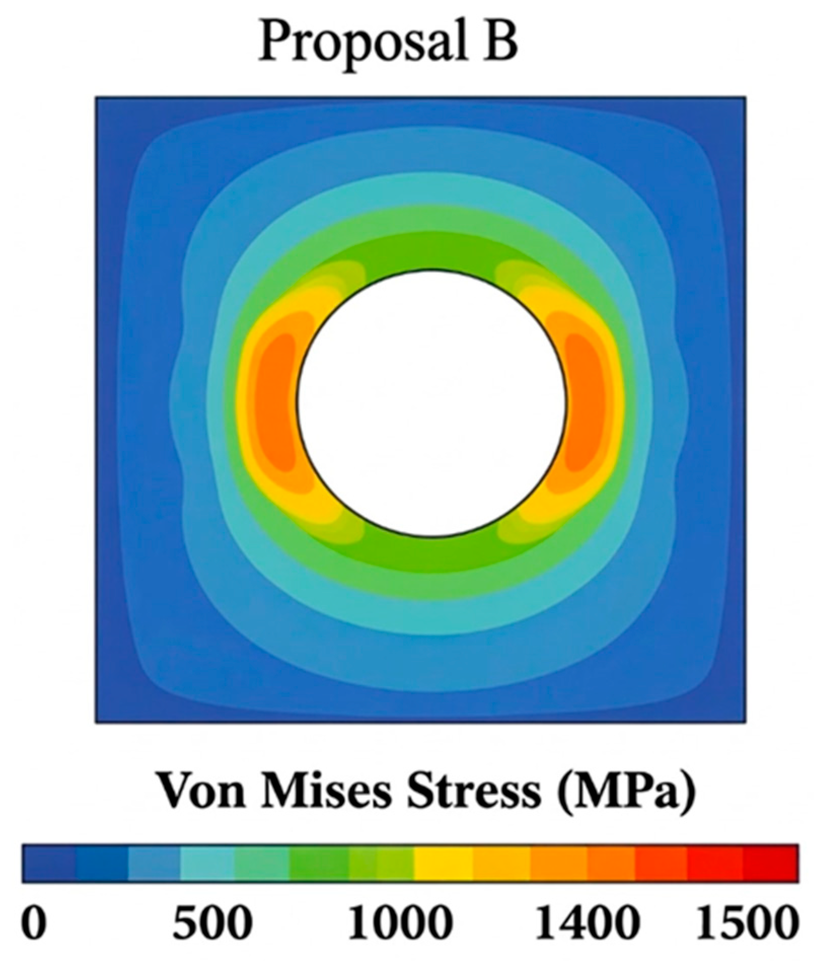
Proposal B combined geometric refinement with increased structural stiffness of the die material. The resulting stress field, presented in Figure 12, exhibited a significantly more uniform distribution and a noticeable displacement of peak stress locations away from critical geometric discontinuities. This redistribution reduces the likelihood of crack initiation under cyclic loading conditions and improves the mechanical stability of the die under severe forming loads.
Figure 12.
Simulation of the redesigned die with increased stiffness (Proposal B).
To complement the qualitative stress maps presented in Figure 10, Figure 11 and Figure 12, several mechanical indicators were extracted from the numerical simulations to quantitatively compare the three configurations. These results are summarized in Table 3.
Table 3.
Comparative numerical results.
The numerical results indicate that the baseline configuration exhibits the highest stress concentration factor (Kt ≈ 3.3) and the largest strain energy density, indicating a high mechanical driving force for crack initiation and fatigue propagation. Similar behavior has been reported in cold-forging tools where abrupt geometric transitions amplify localized stresses and accelerate fatigue damage [29,34]. Proposal A achieved a moderate improvement through geometric optimization, reducing the maximum equivalent stress by approximately 18% and slightly lowering the overall displacement of the die structure [29].
The most significant improvement was observed in Proposal B, where the combination of geometric refinement and increased structural stiffness produced a more uniform stress distribution. In this configuration, the maximum Von Mises stress decreased by approximately 30% relative to the baseline case (from 2000 MPa to 1400 MPa), while the stress concentration factor was reduced to approximately 2.1. Additionally, both displacement and strain energy density were significantly reduced, indicating improved structural stability under high forging loads [23,29].
A clear quantitative correlation exists between these numerical findings and the experimental evidence. According to the Basquin power-law relationship for fatigue, the number of cycles to failure () is exponentially sensitive to the stress amplitude. Consequently, the 30% reduction in peak Von Mises stress achieved in Proposal B provides a mechanistically consistent explanation for the 416% increase in die service life (from 60,000 to 250,000 parts) observed during production trials [34]. These results demonstrate that the combined strategy of geometric optimization and structural stiffness enhancement effectively reduces critical stress concentrations, providing strong mechanical validation of the proposed die redesign and its contribution to improved operational reliability.
A direct correlation was established between the experimentally observed failure pattern of the P6 die (Figure 2) and the stress distribution predicted by the finite element simulations (Figure 10, Figure 11 and Figure 12). The fracture consistently initiated at the cavity transition radius, which coincides with the region of maximum Von Mises stress identified in the baseline configuration [9].
This agreement confirms that fatigue crack initiation is governed by localized stress concentration under cyclic loading. In the baseline configuration, the elevated stress concentration factor promotes early crack nucleation, leading to premature failure. In contrast, the optimized configurations (Proposals A and B) redistribute the stress field, reduce peak stress intensity, and shift critical stress regions away from geometric discontinuities [29,34].
4. Discussion
The results demonstrate that die durability in high-volume cold forging is governed by the interaction between geometric stress concentration, cyclic loading severity, and structural stiffness distribution. The attack angle and chamfer length directly control material flow kinematics and contact pressure gradients at the die–workpiece interface. Increasing the attack angle to 16° and optimizing the chamfer length to 1.4 mm promoted a smoother strain path and reduced localized plastic constraint at the cavity transition, thereby lowering stress triaxiality and mitigating peak equivalent stresses. This confirms that geometric discontinuities act as primary stress raisers and fatigue initiators, reinforcing geometry as a dominant factor in die life [27].
Reducing rotational speed to 88 rpm decreased strain-rate effects and dynamic impact loading, limiting cyclic stress amplitude and frictional heat generation. From a fatigue mechanics perspective, this reduction in loading frequency decreases cumulative damage per unit time and delays crack nucleation under multiaxial stress states, consistent with studies on cyclic degradation in forging tools [35].
The FEA results further revealed that geometric refinement combined with increased effective stiffness (E = 270 GPa, ν = 0.28) redistributed stress fields and shifted maximum Von Mises stresses away from critical transition radii. Lower peak stress intensity reduces the likelihood of micro crack initiation and propagation under repeated compressive–shear cycles. The coherence between multi-Vari dispersion patterns and stress-field redistribution validates the mechanical consistency of the Shainin-based dominant-variable identification strategy [14] and aligns with integrated structural design frameworks in cold-forging die optimization [30].
To further contextualize these findings, a quantitative comparison with recent studies on cold-forging die optimization was conducted. Recent literature reports stress reductions typically ranging between 12% and 25%, with corresponding improvements in tool life between 60% and 180%, depending on the applied strategy, including geometric optimization, surface engineering, and process parameter adjustment [11,30,36]. A quantitative comparison with these studies is presented in Table 4. In contrast, the present study achieved a stress reduction of approximately 30% and a service life increase of 416%, indicating a significantly higher level of performance improvement. Additionally, the reduction in the stress concentration factor from 3.3 to 2.1 reflects a substantial mitigation of localized stress amplification associated with fatigue crack initiation [29,34].
Table 4.
Quantitative comparison of die optimization results with the recent literature.
This comparison highlights the effectiveness of the proposed integrated methodology, which combines empirical dominant-variable identification with numerical validation, achieving superior performance under real industrial conditions. The results demonstrate that the simultaneous control of geometry, process parameters, and structural stiffness provides a more robust and scalable solution than conventional single-strategy optimization approaches. Overall, the intervention produced a mechanically substantiated service-life increase of 416%, demonstrating that coupling geometric control, process-parameter management, and structural reinforcement constitutes an effective fatigue-mitigation strategy.
5. Conclusions
The structured integration of the Dorian Shainin dominant-variable methodology with controlled industrial experimentation and finite element analysis (FEA) enabled the technically substantiated optimization of the P6 die operating under high-volume cold-forging conditions. The study systematically identified the geometric and operational parameters governing stress redistribution, fatigue progression, and process stability within the tooling system.
Empirical convergence isolated three dominant variables—attack angle, chamfer length, and machine rotational speed (RPM)—as the principal drivers of die degradation. The optimized configuration (16° attack angle, 1.4 mm chamfer length, and 88 RPM) established a mechanically favorable loading regime, increasing service life by more than 50%. Geometric refinement reduced stress concentration at critical cavity transitions, while speed reduction mitigated cyclic stress amplitude and friction-induced thermal effects, thereby delaying crack initiation.
Multi-Vari analysis confirmed the progressive stabilization of intra- and inter-batch variability, demonstrating that durability improvement resulted from controlled parameter interaction rather than isolated factor adjustment. FEA results corroborated these findings by revealing the redistribution of and reduction in peak Von Mises stresses. Enhanced structural stiffness (E = 270 GPa, ν = 0.28) further improved load transfer and decreased localized deformation, reducing fatigue risk under repeated compressive–shear cycles.
Operationally, the redesigned configuration increased output from approximately 60,000 to over 250,000 parts per cycle, substantially lowering tooling consumption, downtime, and production cost. The integration of Shainin’s Red X philosophy with physics-based numerical validation establishes a reproducible and scalable framework for tooling optimization in automotive cold-forging systems, contributing both to industrial competitiveness and to applied engineering knowledge.
Author Contributions
Conceptualization, D.D.-S., P.Y.-C. and B.A.-J.; methodology, D.D.-S. and P.Y.-C.; software, D.D.-S.; validation, M.A.C.-C.; F.J.S.-B., P.Y.-C. and B.A.-J.; formal analysis, D.D.-S.; investigation, D.D.-S.; resources, D.D.-S.; data curation, D.D.-S.; writing—original draft preparation, D.D.-S.; writing—P.Y.-C.; visualization, F.J.S.-B.; supervision, B.A.-J. and P.Y.-C.; project administration, D.D.-S.; funding acquisition, D.D.-S. All authors have read and agreed to the published version of the manuscript.
Funding
This research was supported by the Universidad Politécnica de Guanajuato. The article processing charge (APC) was also funded by the Universidad Politécnica de Guanajuato.
Institutional Review Board Statement
Not applicable.
Informed Consent Statement
Not applicable, as this study did not involve human participants.
Data Availability Statement
The original contributions presented in this study are included in the article. Further inquiries can be directed to the corresponding authors.
Acknowledgments
The authors are grateful to the Universidad Politécnica de Guanajuato for the support provided in the development of this study.
Conflicts of Interest
The authors declare no conflicts of interest.
References
- Petkar, P.M.; Gaitonde, V.N.; Karnik, S.R.; Kulkarni, V.N.; Raju, T.K.G.; Davim, J.P. Analysis of forming behavior in cold forging of AISI 1010 steel using artificial neural network. Metals 2020, 10, 1431. [Google Scholar] [CrossRef] [Scilit]
- Kolpak, F.; Hering, O.; Tekkaya, A.E. Consequences of large strain anisotropic work-hardening in cold forging. Int. J. Mater. Form. 2021, 14, 1463–1481. [Google Scholar] [CrossRef] [Scilit]
- Akyıldız, Y.; Kutsal, Ü.; Arslan, Y.; Akman, A.; Karkinli, A.; Sağlam, M.; Yamanoğlu, R. Investigating the effect of heat treatment on the cold forging of 27MnB4 steel via CALPHAD methodology and FEM. Konya J. Eng. Sci. 2023, 11, 59–70. [Google Scholar] [CrossRef] [Scilit]
- Park, S.-N.; Hong, J.-P.; Song, J.-W.; Kang, J.-H. Study on cold forging process design for automotive components of Al 6061 alloys. Int. J. Eng. Trends Technol. 2024, 72, 113–119. [Google Scholar] [CrossRef] [Scilit]
- Hamid, N.A.; Kim, K.M.; Hwang, T.M.; Choi, J.M.; Joun, M.S. Tribological shifting phenomena during automatic multistage cold forging of an automotive Al6082-T6 steering yoke. J. Manuf. Process. 2024, 114, 178–195. [Google Scholar] [CrossRef] [Scilit]
- Lim, J.; Hwang, S.; Lee, S.; Jang, B. The effect of heat treatment and cold forging on the mechanical properties of SCr420 low-alloy steel. Metals 2025, 15, 336. [Google Scholar] [CrossRef] [Scilit]
- Afseoren, M.; Ersoz, T.T.; Yildirim, M. Comparison of warm and cold forging with friction welding for inner constant velocity joints (CVJs). Trans. Indian Inst. Met. 2024, 77, 3341–3352. [Google Scholar] [CrossRef] [Scilit]
- Esmailzadeh, M.; Mousavi, R.; Esfahani, M.M.; Pezzato, L.; Karimi, E. Effect of cold forging on mechanical and corrosion behaviors of carbon steel plate. Int. J. Press. Vessel. Pip. 2022, 198, 104659. [Google Scholar] [CrossRef] [Scilit]
- Hawryluk, M.; Lachowicz, M.; Łukaszek-Sołek, A.; Lisiecki, Ł.; Ficak, G.; Cygan, P. Structural Features of Fatigue Crack Propagation of a Forging Die Made of Chromium–Molybdenum–Vanadium Tool Steel on Its Durability. Materials 2023, 16, 4223. [Google Scholar] [CrossRef] [Scilit]
- Seo, Y.H. A study on improving the prediction accuracy of cold forging die life based on quantitative evaluation of phosphate film damage. Sci. Rep. 2023, 13, 16464. [Google Scholar] [CrossRef] [Scilit] [PubMed]
- Dalbosco, M.; da Silva Lopes, G.; Schmitt, P.D.; Pinotti, L.; Boing, D. Improving fatigue life of cold forging dies by finite element analysis: A case study. J. Manuf. Process. 2021, 64, 349–355. [Google Scholar] [CrossRef] [Scilit]
- Tchasse, P.; Liewald, M. Monitoring and prediction of the process energy in multi-stage cold forging using recurrent and self-attention-based neural networks. Int. J. Adv. Manuf. Technol. 2026, 142, 431–441. [Google Scholar] [CrossRef] [Scilit]
- Li, Y.-J.; Ai, C.-S.; Men, X.-H.; Zhang, C.-L.; Zhang, Q. Research on on-line monitoring technology for steel ball’s forming process based on load signal analysis method. Mech. Syst. Signal Process. 2013, 36, 317–331. [Google Scholar] [CrossRef] [Scilit]
- Kováč, J.; Kuvik, T.; Mancel, V.; Krilek, J. Analysis of Failure States of Transportation Vehicles Using the Ishikawa Diagram: A Case Study. Appl. Sci. 2025, 15, 10221. [Google Scholar] [CrossRef] [Scilit]
- Antony, J. Design of Experiments for Engineers and Scientists, 2nd ed.; Elsevier: Oxford, UK, 2014. [Google Scholar] [CrossRef] [Scilit]
- Montgomery, D.C. Design and Analysis of Experiments, 10th ed.; Wiley: Hoboken, NJ, USA, 2019. [Google Scholar]
- Leach, R.K.; Bourell, D.; Carmignato, S.; Donmez, A.; Senin, N.; Dewulf, W. Geometrical metrology for metal additive manufacturing. CIRP Ann. 2019, 68, 677–700. [Google Scholar] [CrossRef] [Scilit]
- Tao, F.; Qi, Q.; Liu, A.; Kusiak, A. Data-driven smart manufacturing. J. Manuf. Syst. 2018, 48, 157–169. [Google Scholar] [CrossRef] [Scilit]
- Czitrom, V. One-factor-at-a-time versus designed experiments. Am. Stat. 1999, 53, 126–131. [Google Scholar] [CrossRef] [Scilit]
- Bonte, M.H.A.; van den Boogaard, A.H.; Huétink, J. An optimisation strategy for industrial metal forming processes. Struct. Multidiscip. Optim. 2008, 35, 571–586. [Google Scholar] [CrossRef] [Scilit]
- Volke, P.; Groche, P. Interfacial heat transfer coefficients in cold forging of stainless steel. Int. J. Mater. Form. 2022, 15, 32. [Google Scholar] [CrossRef] [Scilit]
- Zienkiewicz, O.C.; Taylor, R.L.; Zhu, J.Z. The Finite Element Method: Its Basis and Fundamentals, 7th ed.; Elsevier: Oxford, UK, 2013. [Google Scholar] [CrossRef] [Scilit]
- Huang, Y.; Jiang, J. A critical review of von Mises criterion for compatible deformation of polycrystalline materials. Crystals 2023, 13, 244. [Google Scholar] [CrossRef] [Scilit]
- Sharma, A.; Hussain, V.M.S.; Kumar, P.A.; Raj, M.P. Failure mode and effects analysis of forging die design: An integrated approach. Mater. Today Proc. 2022, 62, 4041–4045. [Google Scholar] [CrossRef] [Scilit]
- Niesłony, A. A Critical Analysis of the Mises Stress Criterion Used in Frequency Domain Fatigue Life Prediction. Fract. Struct. Integr. 2016, 10, 177–183. [Google Scholar] [CrossRef] [Scilit]
- Behrens, B.-A.; Bouguecha, A.; Vucetic, M.; Chugreev, A. Advanced Wear Simulation for Bulk Metal Forming Processes. MATEC Web Conf. 2016, 80, 04003. [Google Scholar] [CrossRef] [Scilit]
- Tzotzis, A.; García-Hernández, C.; Huertas-Talón, J.-L.; Kyratsis, P. CAD-based automated design of FEA-ready cutting tools. J. Manuf. Mater. Process. 2020, 4, 104. [Google Scholar] [CrossRef] [Scilit]
- Baimukhametov, G.; White, G. Development, Verification and Assessment of a Laser Profilometer and Analysis Algorithm for Microtexture Assessment of Runway Surfaces. Sensors 2024, 24, 7661. [Google Scholar] [CrossRef] [Scilit] [PubMed]
- Vazquez, V.; Hannan, D.; Altan, T. Tool life in cold forging—An example of design improvement to increase service life. J. Mater. Process. Technol. 2000, 98, 90–96. [Google Scholar] [CrossRef] [Scilit]
- Wang, Z.; Jiang, C.; Wei, B.; Wang, Y. Numerical Simulation and Process Parameter Optimization of Warm Forging Near-Net Forming for Spiral Bevel Gear. Appl. Sci. 2024, 14, 1147. [Google Scholar] [CrossRef] [Scilit]
- Emamverdian, A.A.; Sun, Y.; Cao, C.; Pruncu, C.; Wang, Y. Current failure mechanisms and treatment methods of hot forging tools (dies)—A review. Eng. Fail. Anal. 2021, 129, 105678. [Google Scholar] [CrossRef] [Scilit]
- Pedersen, T.Ø. Numerical modelling of cyclic plasticity and fatigue damage in cold-forging tools. Int. J. Mech. Sci. 2000, 42, 799–818. [Google Scholar] [CrossRef] [Scilit]
- Byun, J.B.; Razali, M.K.; Lee, C.J.; Seo, I.D.; Chung, W.J.; Joun, M.S. Automatic Multi-Stage Cold Forging of an SUS304 Ball-Stud with a Hexagonal Hole at One End. Materials 2020, 13, 5300. [Google Scholar] [CrossRef] [Scilit]
- Petkar, P.M.; Kulkarni, V.N.; Sidalingeshwar, I.G.; Umarfarooq, M.A.; Khan, T.; Junaedi, H.; Sebaey, T.A. Experimental Investigation of Die Performance in Cold Forging Backward Extrusion. J. Manuf. Mater. Process. 2026, 10, 70. [Google Scholar] [CrossRef] [Scilit]
- Skov-Hansen, P.; Bay, N.; Grønbæk, J.; Brøndsted, P. Fatigue in cold-forging dies: Tool life analysis. J. Mater. Process. Technol. 1999, 95, 40–48. [Google Scholar] [CrossRef] [Scilit]
- Karunathilaka, N.; Tada, N.; Uemori, T.; Hanamitsu, R.; Fujii, M.; Omiya, Y.; Kawano, M. Effect of Lubrication and Forging Load on Surface Roughness, Residual Stress, and Deformation of Cold Forging Tools. Metals 2019, 9, 783. [Google Scholar] [CrossRef] [Scilit]



Disclaimer/Publisher’s Note: The statements, opinions and data contained in all publications are solely those of the individual author(s) and contributor(s) and not of MDPI and/or the editor(s). MDPI and/or the editor(s) disclaim responsibility for any injury to people or property resulting from any ideas, methods, instructions or products referred to in the content. |
© 2026 by the authors. Licensee MDPI, Basel, Switzerland. This article is an open access article distributed under the terms and conditions of the Creative Commons Attribution (CC BY) license.