


Abstract
This study explores the passive separation of solid particles from liquid suspensions in spiral separators fabricated using fused filament fabrication (FFF) and stereolithography (SLA). Building on prior work, we investigate the effect of microchannel geometry, circular vs. square cross-sections of equal area, and printing method on separation performance. Devices were tested across a wider range of flow rates (150 mL min−1–350 mL min−1), extending into transitional regimes, to examine geometry-induced inertial effects. Separation performance was quantified using the normalized outlet mass difference (Δ) for talc, precipitated calcium carbonate, and quartz. Maximum separation was obtained for quartz sand in the SLA separator at 250 mL min−1 (Δ = 0.2175 g per 100 mL), while talc showed the highest mass difference in the square FFF separator at 300 mL min−1 (Δ = 0.1196 g per 100 mL). For calcium carbonate, the highest separation occurred in the SLA device at 250 mL min−1 (Δ = 0.1721 g per 100 mL), though performance was limited by agglomeration and clogging in FFF devices. Overall, separation was predominantly mass-based rather than strictly size-selective, with channel geometry, flow regime, and fabrication method jointly governing performance.
1. Introduction
Millifluidic separation is an emerging technique that enables the manipulation and sorting of particles in liquid samples at the millimeter scale. Unlike microfluidics, which relies on micrometer-sized channels dominated by capillary forces and surface effects, millifluidic systems use channels larger than one millimeter. This design simplifies device fabrication, reduces clogging, and supports higher sample throughput. While millifluidics offers somewhat lower precision in particle control compared to microscale systems, it provides practical advantages such as handling higher particle concentrations, processing larger sample volumes, and maintaining robustness for real-world applications. Another key strength is the balance between scalability and moderate reagent consumption, making millifluidic separation particularly suitable for chemical processing, environmental monitoring, and preparative-scale lab-on-a-chip platforms [1,2,3,4]. Various methods have been developed to separate particles in microfluidic systems, including the use of inertial forces, dielectrophoresis, magnetophoresis, acoustic waves, and hydrodynamic effects. While these techniques can offer high separation efficiency and selectivity, many require complex fabrication processes, precise external field control, or the integration of specialized materials and components [5,6,7]. Such requirements can limit the accessibility, scalability, and cost-effectiveness of microfluidic separation devices, particularly for applications that demand rapid prototyping or customization. As a result, there is growing interest in developing passive, geometry-based separation strategies that rely solely on the internal channel design and fluid dynamics, without the need for external fields or moving parts [8,9].
Additive manufacturing, such as fused filament fabrication (FFF) and stereolithography (SLA), has revolutionized the fabrication of microfluidic devices by enabling rapid prototyping and complex geometries unattainable with traditional methods. Direct ink writing (DIW) is another emerging AM approach, allowing extrusion of functional inks for creating microchannels with customized materials and properties [10]. Recent work by Beauchamp et al. [11] demonstrated how sub-100 µm 3D-printed microchannels can be optimized in terms of geometry and surface quality to enhance inertial focusing and separation performance, highlighting the importance of high-fidelity fabrication for achieving reproducible microfluidic behavior.
FFF offers advantages such as material versatility, ease of use, and cost-effectiveness, particularly with thermoplastics like polyethylene terephthalate glycol (PETG) [12,13,14]. In contrast, SLA provides higher resolution and smoother surface finishes through photopolymerization of liquid resins, which is beneficial for fabricating fine microchannel features [15]. Combining or comparing these complementary techniques broadens the design space for microfluidic separators, allowing researchers to tailor devices to specific separation challenges while balancing fabrication speed, precision, and material properties [16]. Additive manufacturing has also been employed to fabricate a wide range of 3D-printed microfluidic devices and microreactors with complex channel geometries for chemical and environmental applications [17]. This study highlights the versatility of different 3D printing approaches for producing functional flow platforms and high-throughput systems, complementing the exploration of spiral microfluidic separators in this work. Despite advances in 3D printing for microfluidics, the use of spiral microchannel geometries fabricated by both FFF and SLA for solid–liquid separation remains underexplored. Spiral channels are recognized for their ability to induce secondary flows that can manipulate particle trajectories, yet most prior work has focused on liquid–liquid separations or employed costly fabrication techniques [18,19,20]. Utilizing both FFF and SLA to fabricate spiral microfluidic separators allows for a comprehensive study of how fabrication method and channel geometry affect separation performance with heterogeneous powders such as talc, quartz sand, and nano calcium carbonate. This dual-fabrication approach provides valuable insights into the trade-offs between resolution, material compatibility, and separation efficiency, highlighting accessible routes for producing customizable, tailored and scalable microfluidic separation devices. The study’s findings contribute to the development of practical, geometry-driven separation solutions applicable to environmental monitoring, pharmaceuticals, and chemical processing [21,22,23]. In our prior work [1], we developed 3D-printed spiral microfluidic separators using SLA and FFF, demonstrating their effectiveness in separating particles such as talc, quartz sand, and calcium carbonate from aqueous suspensions. That study analyzed separation performance primarily as a function of flow rate and printing technique, and included a detailed analysis of particle size distribution with specific parameters to assess the extent of size-selective separation. While mass differences between outlets indicated partial separation, the particle size distributions at the outlets remained mostly unchanged, suggesting limited size resolution and motivating future studies on the effect of internal geometry on separation outcomes [24,25].
In contrast to our prior work [1], SLA devices were fabricated with both circular and square cross-sections, while FFF was restricted to circular channels, and flow rates were limited to the range of 200 mL min−1 to 300 mL min−1. In the present study, SLA is used instead to produce circular channels with different diameters compared to the previous study, and FFF is additionally used to fabricate both circular and square cross-sections. This broader design enables a clearer assessment of how fabrication method, channel geometry, and size will affect inertial and secondary flow phenomena. Furthermore, the tested flow rate domain has now been set to 150 mL/min to 350 mL/min, enabling the study of the behavior closer to the onset of transition from laminar to turbulent regimes. Also, this study integrates computational fluid dynamics (CFD) simulations performed in COMSOL Multiphysics to support and validate the experimental observations. Such simulation-based confirmation of flow behavior was not revealed in our prior work and is not commonly applied in studies of 3D-printed spiral microfluidic separators, highlighting a further novel contribution of this research. Overall, this additional in-depth analysis allows a more systematic assessment of how fabrication method, channel geometry, and flow conditions interact to determine passive separation performance in 3D-printed microfluidic systems.
Building on our earlier exploration of 3D-printed spiral microfluidic separators, this study continues and expands research outcomes by studying how printing technologies, channel geometries, and particle properties collectively affect separation performance. While our previous work established the potential of SLA and FFF fabrication for passive solid–liquid separation, the present study covers a higher range of tested flow rates, includes additional channel geometries, and applies more detailed characterization techniques. This approach provides a more comprehensive understanding of how design and fabrication parameters interact with suspension properties to affect separation behavior.
The primary objective of this study was to design, fabricate, and evaluate the performance of spiral microfluidic separators using both FFF and SLA 3D printing technologies. Devices featuring varied cross-sectional spiral channel geometries, while maintaining consistent cross-sectional areas, were produced using thermoplastic filament for FFF and a photocurable resin for SLA. 3D printed devices were tested on solid–liquid suspensions containing talc, quartz sand, and nano calcium carbonate. Particle characterization preceded separation trials, with outcomes assessed through mass distribution measurements and particle size analyses at outlets of microfluidic separators. By systematically comparing the influence of channel geometry and fabrication method on separation behavior, this research addresses a critical gap in the field of microfluidics [26,27,28]. The demonstration of low-cost, customizable, tailored and passive microfluidic separators manufactured via complementary 3D printing approaches underscores the work’s significance, offering new avenues for accessible particle separation technologies.
Despite considerable progress in 3D-printed microfluidic separators, several points remain debated. The influence of channel cross-sectional geometry on particle focusing and inertial separation is not fully agreed upon, with some studies suggesting circular or planar channels are sufficient, while others indicate that square or non-circular geometries can enhance secondary flows and improve particle migration. The effect of flow rate on separation efficiency is similarly inconsistent, particularly for cohesive or very fine particles, where high velocities may either improve throughput or destabilize particle trajectories. Moreover, passive separation effectiveness for particles smaller than 10 µm remains uncertain, and the role of the fabrication method in achieving reproducible channel geometries and surface smoothness adds further complexity. Collectively, these open questions highlight the need for systematic studies that compare multiple channel shapes, fabrication approaches, and flow conditions, and that combine experimental evaluation with computational dynamics to provide mechanistic insight. The present study addresses these gaps by evaluating both FFF and SLA-printed spiral separators with circular and square cross-sections, across an expanded flow rate range, using powders of differing size, shape, and cohesiveness, and corroborating observations with CFD simulations to better understand flow-particle interactions.
While our previous study [1] investigated square and circular channels with different dimensions and numbers of turns, the present work further expands this design space by systematically evaluating spiral channels of equal cross-sectional area across both FFF and SLA fabrication methods. The current study explores a broader range of flow rates (150 mL min−1–350 mL min−1), includes additional geometries and integrates CFD simulations to analyze flow profiles within the channels, supporting interpretation of the experimental separation trends. Together, the two studies provide a more comprehensive assessment of how channel geometry, fabrication technique, and flow conditions influence separation efficiency, particle focusing, and device operability, highlighting both practical and fundamental advances over prior work. The novelty of this work lies in systematically comparing circular and square spiral channels fabricated via FFF and SLA, across an expanded flow rate range, and linking geometry, fabrication method, and flow conditions to passive solid–liquid separation performance.
2. Materials and Methods
2.1. Materials
Spiral separators were designed using Autodesk Fusion CAD software (v.2.0.19941). The internal channel geometry consisted of spiral-shaped pathways with varied cross-sectional profiles, while the overall cross-sectional areas were kept constant for both square and circular channel designs, enabling a direct comparative analysis. The channel diameters and number of spiral turns were chosen based on previous studies [1], balancing flow stability, separation efficiency, and fabrication constraints. FFF devices use 2 mm circular and 1.77 mm square channels with eight turns, while SLA devices use 3 mm circular channels with six turns. These choices allow meaningful exploration of geometric effects while remaining within the manufacturing capabilities of each technique.
For FFF, the CAD models were exported in STL format and prepared using PrusaSlicer (v.2.8.0)with the built-in PETG material preset. The devices were printed using a Prusa i3 MK3s+ 3D printer (Prusa Research, Prague, Czech Republic) with 1.75 mm PETG filament (Devil Design Sp. J., Mikołów, Poland; product no: 5GJG151534). Printing was carried out with a nozzle temperature of 230 °C and a heated bed temperature of 85 °C, using a layer height of 0.05 mm and 100% infill set to ensure watertight channels and maximum mechanical stability. The FFF devices were printed under ambient laboratory conditions without controlled humidity. For SLA, the same STL files were sliced using PreForm software (v.3.43.1) and printed on a Formlabs Form 2 printer (Formlabs, Somerville, MA, USA) using Formlabs Clear Resin V4 (Formlabs, Somerville, MA, USA), using a layer height of 0.05 mm. Following printing, parts were rinsed in isopropanol to remove uncured resin and then cured under UV light to achieve full polymerization effect and optimal mechanical stability according to the manufacturer’s guidelines.
2.2. Separator Design
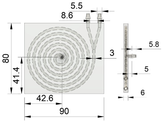
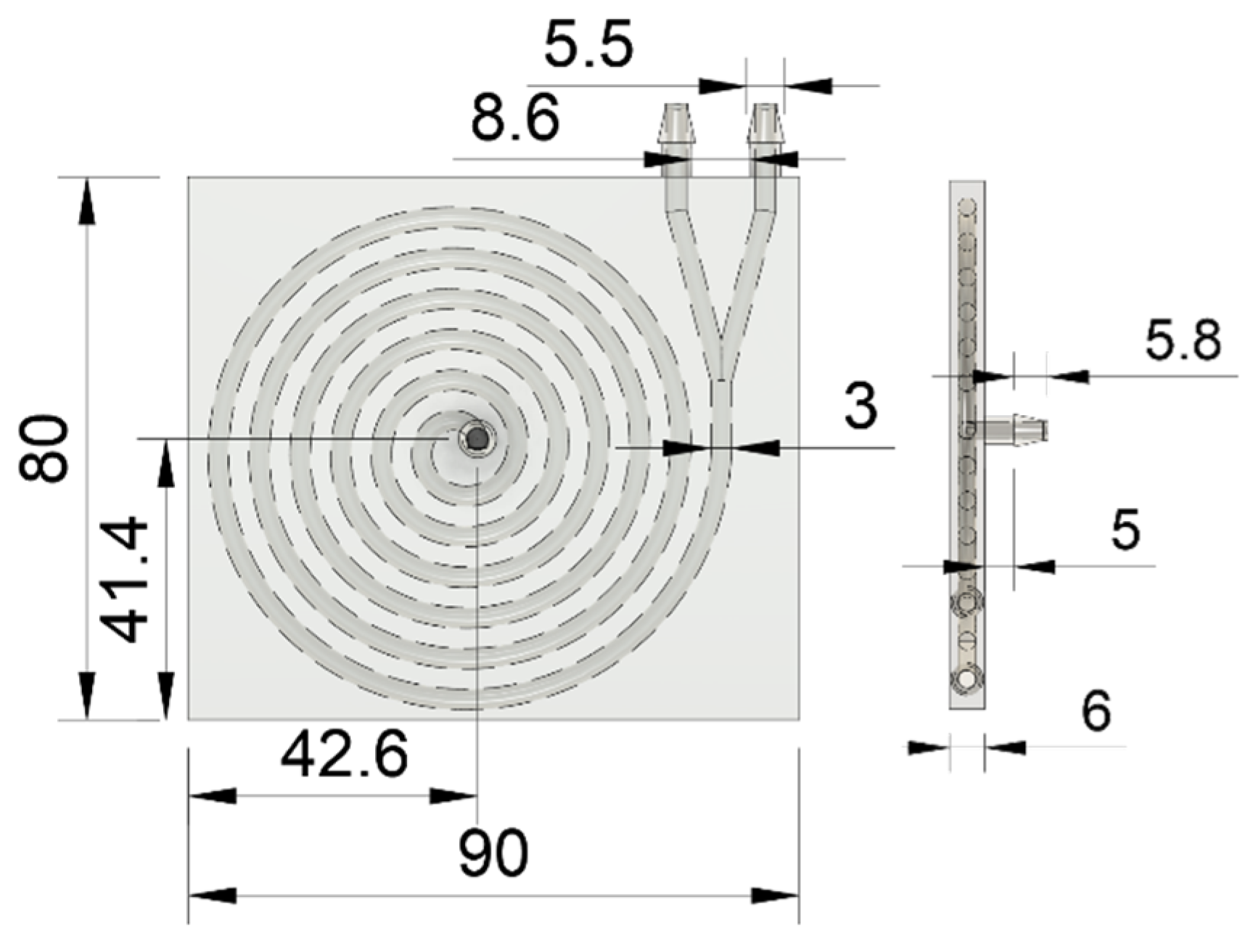
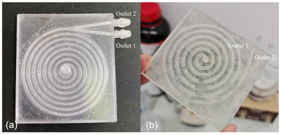
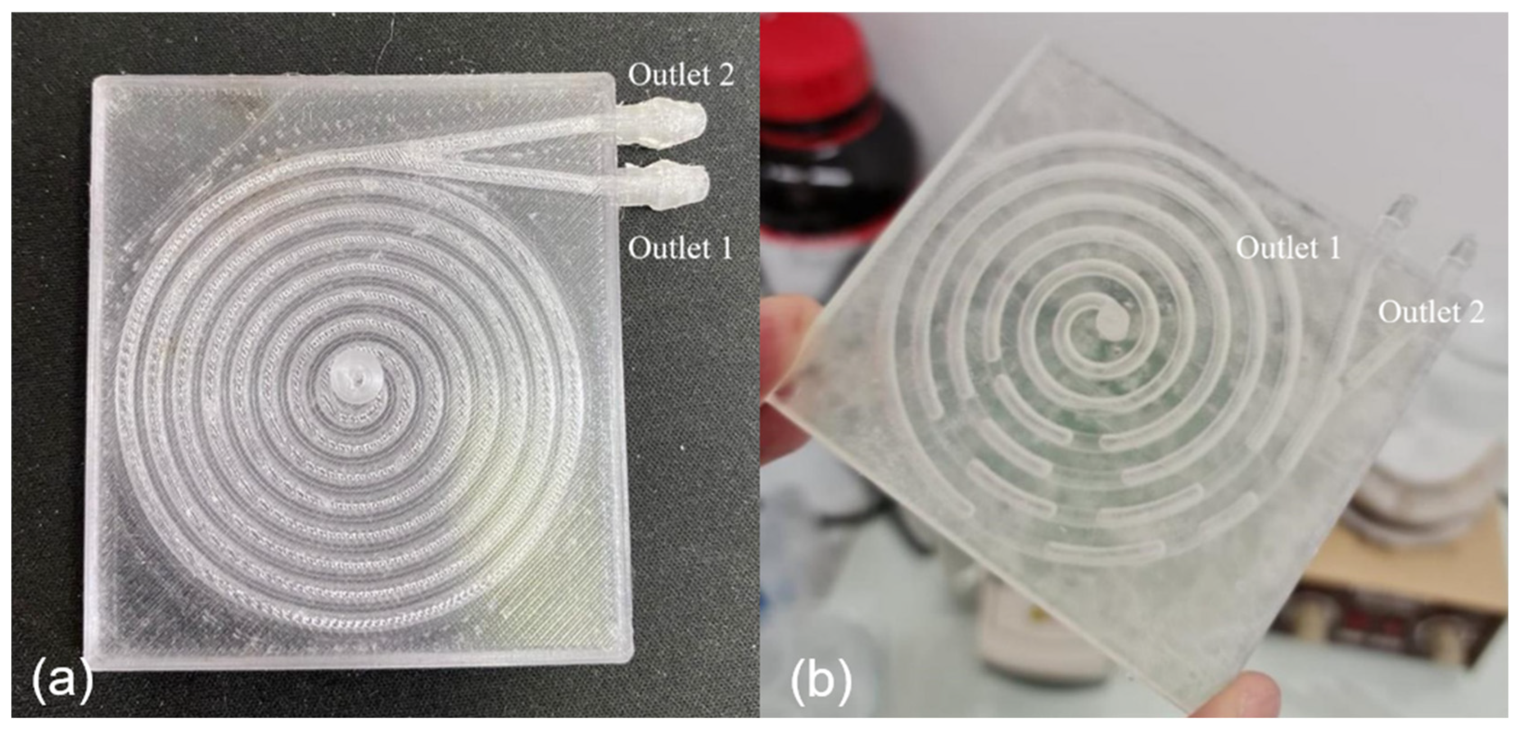
There are several key geometry parameters in separator design, such as width and length of channel, wall thickness, spiral channel dimensions, and the number of turns, as illustrated in Figure 1. The design, based on prior research [1], features a single inlet located at the top of the separator and two side-positioned outlets, labelled as Outlet 1 (external stream) and Outlet 2 (internal stream), as shown in Figure 2. The separators are categorized and named by manufacturing method and channel cross-section: FFF1 (circular cross-section), FFF2 (square cross-section), and SLA (circular cross-section). FFF separators are designed with eight spiral turns, while the SLA separator has six turns (Table 1). These variations in material, manufacturing technology, and channel geometry were selected to evaluate their effect on separation efficiency.
Figure 1.
Separator model with dimensions in millimeters.
Figure 2.
Spiral separators printed by FFF ((a), PETG) and SLA ((b), Clear Resin V4).
Table 1.
Geometry for each fabricated and tested separator.
These geometries are based on the separator design introduced in our previous study [1], with controlled modifications to the channel cross-section. In the FFF devices, the cross-sectional area was kept constant to isolate the effects of profile shape, whereas the SLA device incorporated a larger 3 mm circular channel. This design strategy enables more in-depth insight into how channel geometry affects separation, independent of flow rate or particle type.
2.3. Separation Process
The suspension was prepared by mixing powder and water at a ratio of 1 g of powder to 300 g of water. The powders used for testing separation efficiency were: CaCO3, supplied by Schaefer Kalk GmbH (Diez, Germany), commercially known as Precarb 400, which has a specific surface area of 8 m2 g−1 and a bulk density ranging from 200 to 600 g dm−3, quartz sand, supplied by Samoborka (Samobor, Croatia), with bulk density of 1380 ± 50 kg m−3, and baby powder, finely produced by Gradske ljekarne Zagreb (Zagreb, Croatia), consisted primarily of talc and zinc oxide. To improve dispersion of the talc within the suspension, 30 mL of isopropyl alcohol was added.
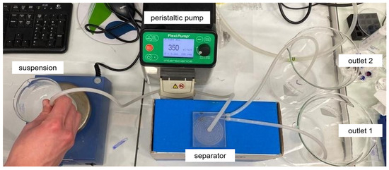
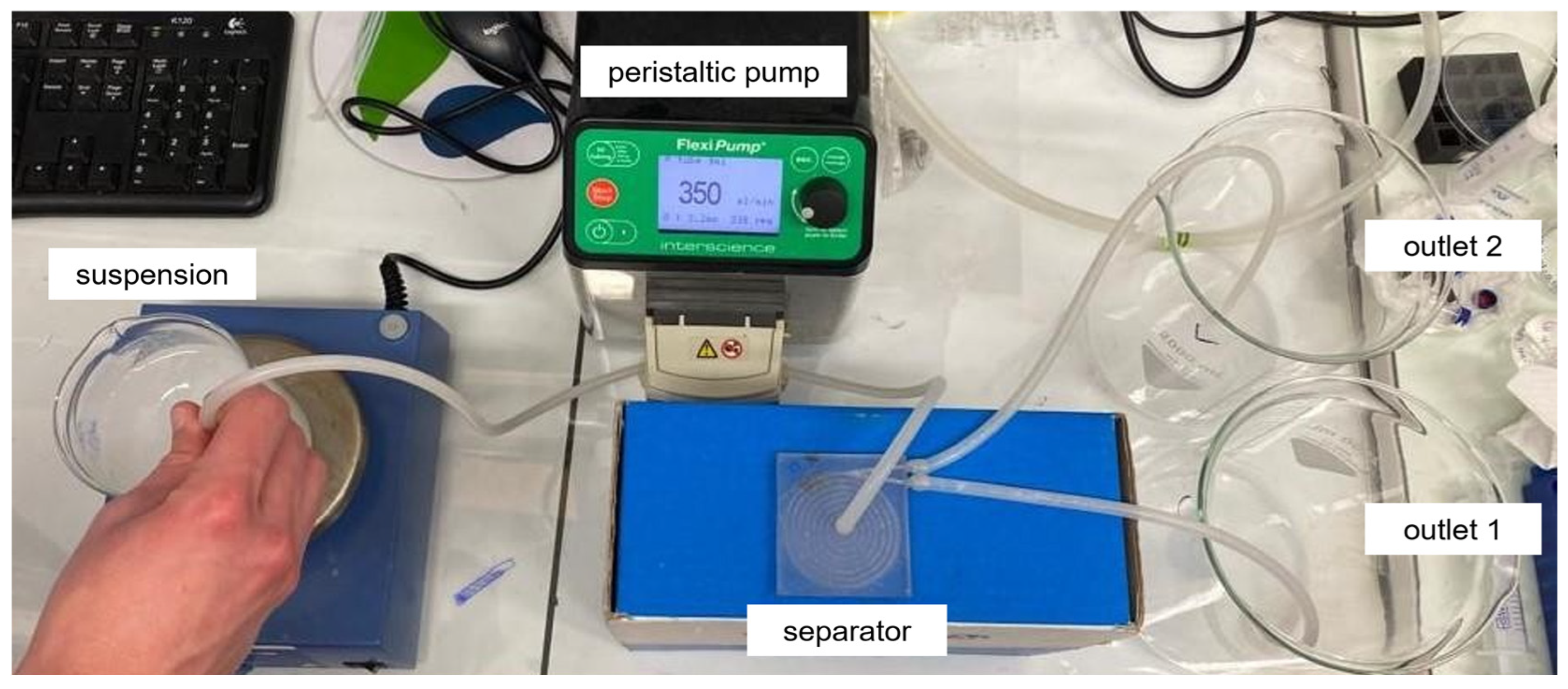
The separation apparatus consisted of an IKA RCT digital magnetic stirrer (Ika Werke GmbH, Staufen im Breisgau, Germany), on which the suspension container was placed, a FlexiPump peristaltic pump (INTERSCIENCE, Shah Alam, Malaysia), the fabricated separator device, and the two collection vessels for the separated products (Figure 3).
Figure 3.
Separation apparatus.
A higher degree of particle dispersion in the suspension was achieved by using a magnetic stirrer. Once complete suspension had been confirmed using the 1 s rule, the peristaltic pump was used to drive the suspension flow through tubing toward the separator, while continuous stirring was maintained using a magnetic stirrer. Since the suspension contains coarse particles, the peristaltic pump should also prevent particle contact with the pump’s internal components. The silicone tubing exiting the suspension container passes through the front section of the pump, where the rotor’s rotation and cyclical compression of the tubing facilitate the suspension’s movement to the separator. Separation experiments were run at flow rates ranging from 150 mL min−1 to 350 mL min−1.
As the initial suspension was split into two outlet streams (internal and external), the volumes of both streams were tracked, and vacuum filtration was additionally performed to separate the remaining liquid and solid phases. The difference in mass provides the amount of powder collected from the internal and external outlet streams, respectively.
2.4. Characterization
Powder characterization was performed both before and after the separation process. Initial powder analysis was conducted to determine and define the particle size distribution (PSD) in the inlet suspension, while the particle size distribution in the outlet streams was analyzed after separation to assess any PSD changes resulting from the process, thus indicating the performance of the tested separator. Sieve analysis, laser diffraction analysis, and scanning electron microscopy were used to characterize powders before and after the separation process. Firstly, seven wire mesh sieves with openings ranging from 850 µm to 63 µm (850 µm, 710 µm, 355 µm, 180 µm, 125 µm, 90 µm and 63 µm) were used to fractionate the polydisperse powder into several distinct size intervals. The Retsch AS 200 sieve shaker (Retsch GmbH, Haan, Germany) is additionally used as it provides reproducible and more efficient particle size separation of powders. Each fraction, retained on the specific sieve, was weighed to collect the differential particle size distribution data. Laser diffraction measurements were additionally conducted using a Shimadzu SALD-3101 size analyzer (Shimadzu, Kyoto, Japan) to discover PSD data more closely. All tests were performed under wet conditions (samples were previously suspended in demineralized water) with continuous stirring to break down any potential agglomerates. Each sample was scanned five times under identical process conditions in order to test the reproducibility and to gain more representative particle size distribution (PSD) data for each tested sample. The net size distribution data were provided by averaging the five size distribution data for each size interval. Average PSD data collected using a laser size analyzer are expressed on a volume basis, while those from sieve analysis are on a mass basis. PSD data are reported via differential distribution function, dQ3(d), and for the case of laser diffraction analysis, additionally with characteristic diameters: d50 as a median diameter, dmode as a modus diameter (dominant size in a population), and diameter mean, d3,2. The mode diameter (dmode) refers to the particle size with the highest frequency in the distribution, i.e., the most abundant size class detected in the sample. The median diameter (d50) represents the particle size at which 50% of the cumulative distribution (by volume, number, or mass, depending on the chosen basis) lies below and 50% lies above. It is therefore a robust descriptor of the central tendency of the distribution and is widely used as a standard measure of “average” particle size. The surface-area-weighted mean diameter (d3,2), also known as the Sauter mean diameter, is also used and corresponds to the diameter of a sphere with the same volume-to-surface area ratio as the particles in the sample. This parameter emphasizes the contribution of smaller particles due to their higher surface area-to-volume ratio. As previously stated, for talc particles, isopropyl alcohol was added as needed to improve dispersion. Scanning electron microscopy (SEM) was performed using a Tescan Vega 3 microscope (Tescan, Brno, Czech Republic). Non-conductive samples were coated with a gold–palladium alloy under an argon atmosphere using a sputter coater to enable successful imaging.
2.5. Computational Fluid Dynamics (CFD) Simulations
To complement the experimental investigations, numerical simulations were conducted as well using COMSOL Multiphysics (v6.3, COMSOL AB, Stockholm, Sweden). The spiral channel geometries (FFF1, FFF2, and SLA) were directly imported from CAD designs to ensure consistency with fabricated devices. The Laminar Flow physics interface was employed to model the steady-state flow of an incompressible Newtonian fluid. The simulations solved the continuity and Navier–Stokes equations under laminar flow conditions.
Simulation parameters were matched to experimental conditions. The inlet boundary condition was specified as a fully developed volumetric flow rate ranging from 150 mL min−1 to 350 mL min−1, while the outlet was defined using a pressure boundary condition set to 0 Pa. No-slip conditions were applied at all channel walls.
Water was assigned as the carrier fluid, with density and viscosity based on experimental values. The computational domain was discretized using a tetrahedral mesh. A coarse mesh setting was initially employed, with a maximum element size of 9.36 × 10⁻⁴ m and a minimum element size of 2.81 × 10⁻⁴ m. Mesh refinement was automatically applied in regions with geometric curvature. The final computational mesh consisted of approximately 176,848 tetrahedral elements.
A mesh independence study was performed by comparing simulation results obtained using a coarse mesh with those obtained using a refined mesh. Key flow characteristics, including velocity distribution and pressure drop along the channel, showed no noticeable differences between the two mesh resolutions. The numerical simulation was therefore considered mesh-independent, and the coarse mesh was adopted for all simulations to reduce computational cost.
The CFD results were used to analyze velocity fields and secondary flow structures within the spiral channels, providing mechanistic insight into the experimentally observed separation trends. While the simulations provide detailed information on the velocity fields and secondary flow structures, they do not account for particle rotation, orientation-dependent drag, agglomeration, or particle–particle interactions. Wall roughness and transitional flow effects at higher Reynolds numbers are also neglected. Despite these simplifications, the computed flow patterns offer useful mechanistic insight into regions of high or low velocity that influence particle transport and the trends observed in the experiments.
3. Results and Discussion
3.1. Characterization of Powders Before the Separation
Powders were characterized before and after separation. Prior to separation, the powder was analyzed to detect the size distribution of particles in the feed stream. Following the separation process, particle size characterization of the powder in the outlet streams was carried out to discover the correlation between particle size and separation behavior.
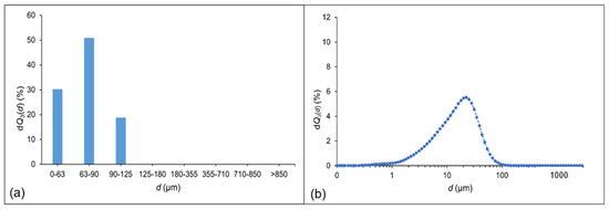
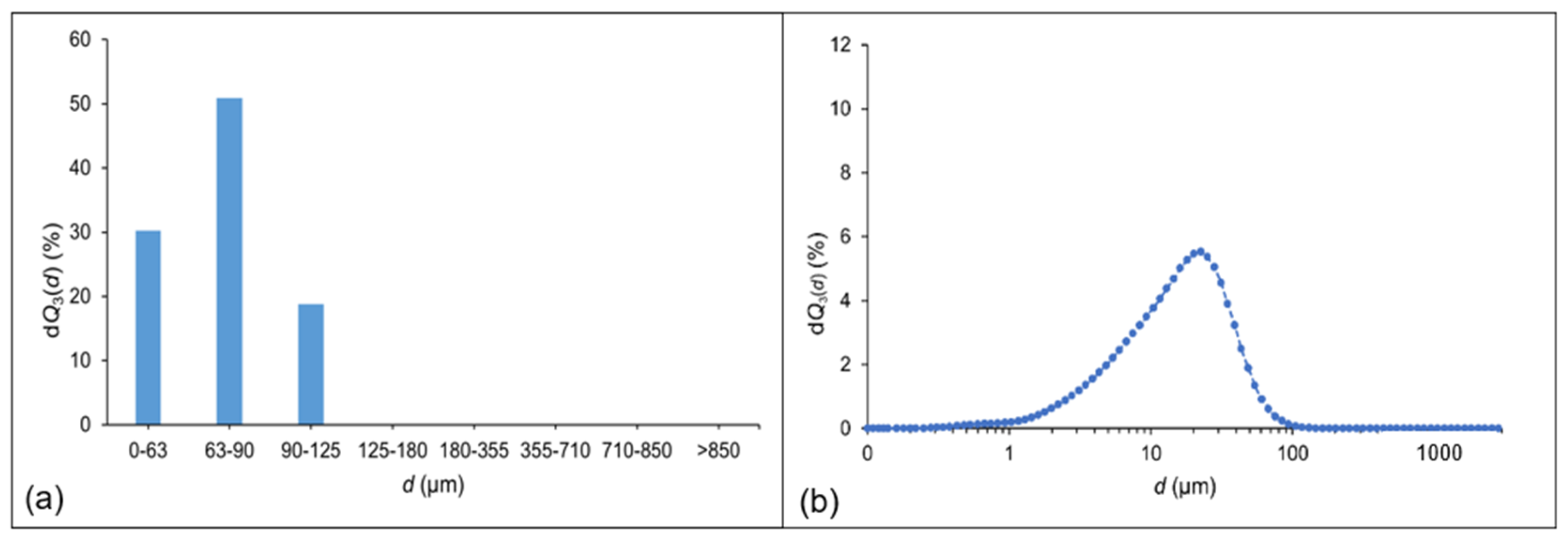
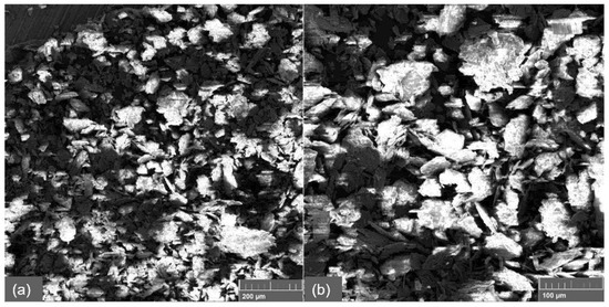
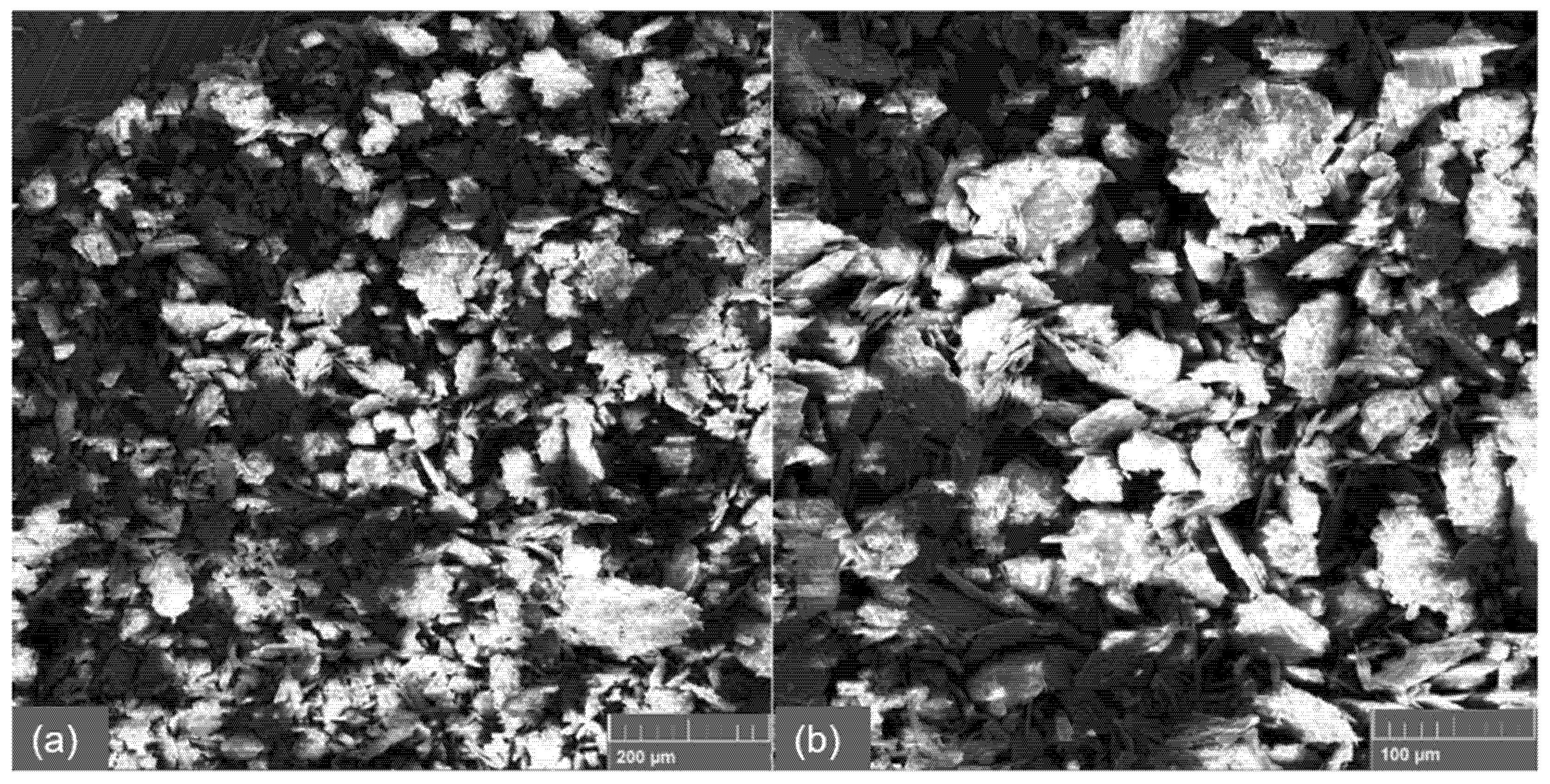
The graphical representation in Figure 4 shows that 30.27% of the powder particles fall within the 0 μm to 63 μm size range. The largest fraction, comprising 50.92% of the particles, is found in the 63 μm to 90 μm range, while 18.81% of the particles are within the 90 μm to 125 μm interval. The laser diffraction analysis of baby powder shows that a large proportion of particles falls within the size range of 0 to 70 μm. This indicates a predominance of finer particles in the sample. The Sauter mean diameter is 43 μm, reflecting a relatively small average particle size. In addition to particle size, morphology plays a crucial role in determining flow behavior. SEM analysis (Figure 5) reveals that the talc particles are not spherical, but instead exhibit a plate, flaky morphology, with dimensions ranging approximately from 20 μm to 60 μm. This anisotropic shape means their hydrodynamic behavior is strongly dependent on orientation. When aligned broadside to the flow, the fluid interacts with the large surface area, making the particle behave as if it were much larger and generating a higher drag force. In contrast, when oriented edge-on, the particle presents a smaller effective area to the flow, behaving more like a finer particle with reduced resistance. This duality means talc particles cannot be characterized by size distribution alone, as their separation dynamics will be affected by random rotation and reorientation within the flow. Such orientation-dependent behavior can complicate classification, as the same particle may alternately settle or be carried with the flow depending on how it is aligned.
Figure 4.
Graphic view of experimental PSDs for pre-separated talc: (a) sieve analysis and (b) laser diffraction analysis.
Figure 5.
SEM micrographs of pre-separated talc at (a) 200× magnification and (b) 500× magnification.
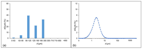
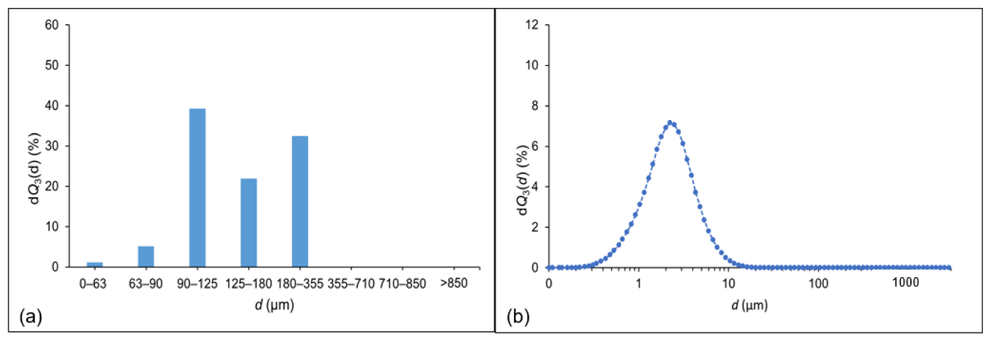
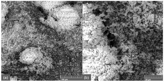
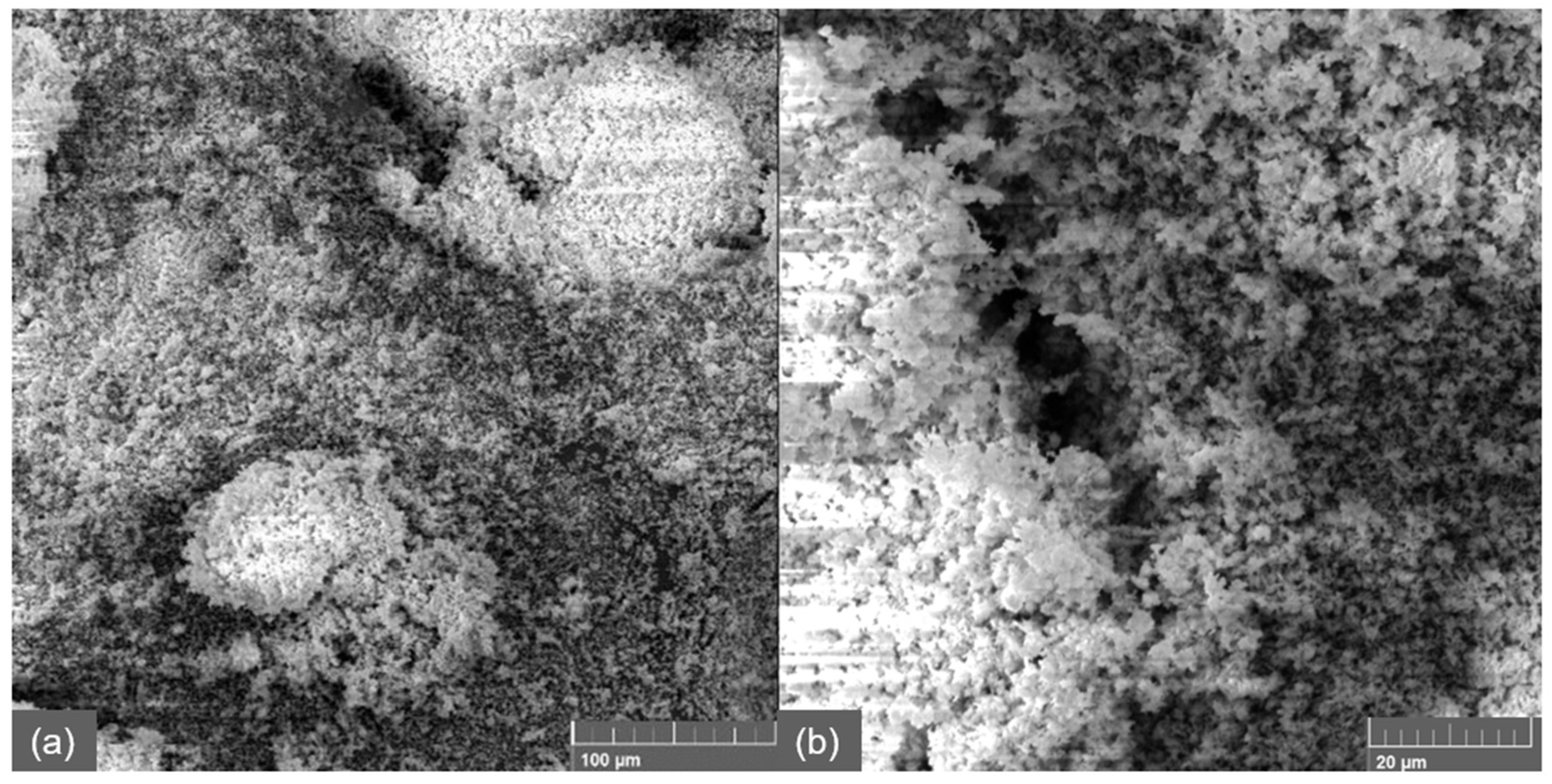
The highest proportion of nano CaCO3 particles was found in the size range of 90 µm to 125 µm by the sieve analysis, accounting for 39.26% of the total sample. The second most abundant fraction, comprising 32.47% of the particles, was found in the 180 µm to 355 µm range. Additional particle fractions were observed in the 125 µm to 180 µm and 63 µm to 90 µm intervals, while the smallest fraction, only 1.12%, was detected in the 0 µm to 63 µm range. It should be noted that in sieve analysis, very small particles can remain suspended in the air “cloud” above the sieve and fail to reach the bottom to be weighted, likely leading to an underestimation of the finest fraction. Given that the measured particle sizes are in the micrometer scale, despite the sample being designated as nano CaCO3, it can be concluded that particle agglomeration occurred. Laser diffraction analysis revealed that the majority of particles are within the 0 µm to 10 µm size range, with both the median and the most frequent particle sizes being around 2 µm, and a Sauter mean diameter of approximately 6 µm (Figure 6). However, since this method requires the addition of a liquid, it can promote further agglomeration, potentially altering the effective particle size distribution compared to the dry state. Considering these limitations, scanning electron microscopy (SEM) provides a more reliable assessment of individual particle sizes and the extent of agglomeration in this sample (Figure 7).
Figure 6.
Graphic view of experimental PSDs for pre-separated nano CaCO3: (a) sieve analysis and (b) laser diffraction analysis.
Figure 7.
SEM micrographs of pre-separated nano CaCO3 at (a) 500× magnification and (b) 2000× magnification.
The wide particle size distribution and strong agglomeration make the separation of CaCO3 particles challenging. This difficulty is further compounded by the low bulk density of CaCO3, which is smaller than that of water. In spiral separators, Dean forces generate secondary vortices that create specific lateral equilibrium positions within the channel. Heavier and larger particles experience stronger inertial lift and are pushed toward the outer edges of the spiral, while smaller or lighter particles are expected to migrate closer to the inner edges. However, low-density or very small particles, such as individual CaCO3 particles or loosely bound agglomerates, experience insufficient forces to reach these positions. They remain widely dispersed across the channel rather than concentrating where separation occurs, drastically reducing the efficiency of the process, particularly for the smallest or lightest fractions.
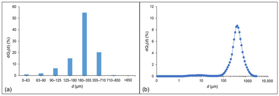
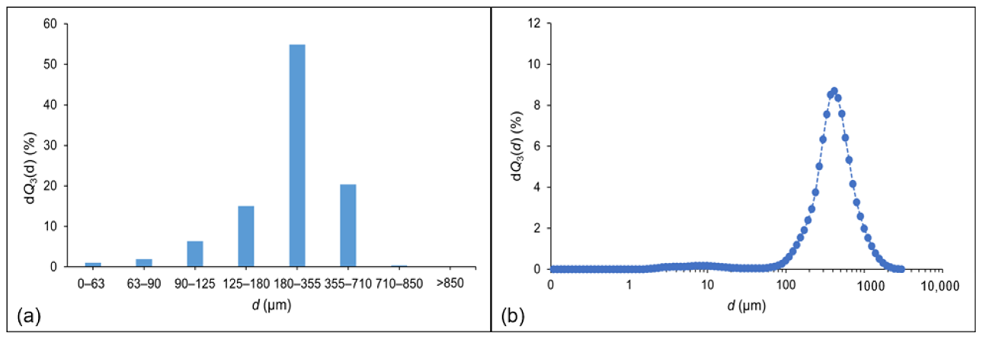
Sieve analysis showed that quartz sand exhibits the widest particle size distribution among the analyzed samples. The highest proportion of particles was found in the 180 µm to 355 µm size range, although all observed size intervals contain a measurable fraction of the sample. Laser diffraction analysis indicates that the majority of quartz sand particles fall within the 100 µm to 1 mm range (Figure 8), with the most frequent particle size around 350 µm, the median at 280 µm, and a Sauter diameter of approximately 800 µm.
Figure 8.
Graphic view of experimental PSDs for pre-separated quartz sand: (a) sieve analysis and (b) laser diffraction analysis.
Statistical parameters, such as the mean diameter and standard deviation (σ), for each particle size distribution (Table 2) were obtained using the particle size distribution analysis tool Hyprotech Explorer (HYSYS® v2004.2) with fitting options.
Table 2.
PSD statistical parameters for each pre-separated sample.
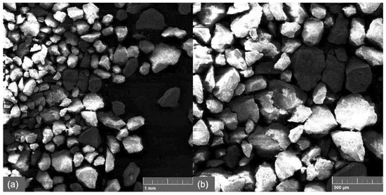
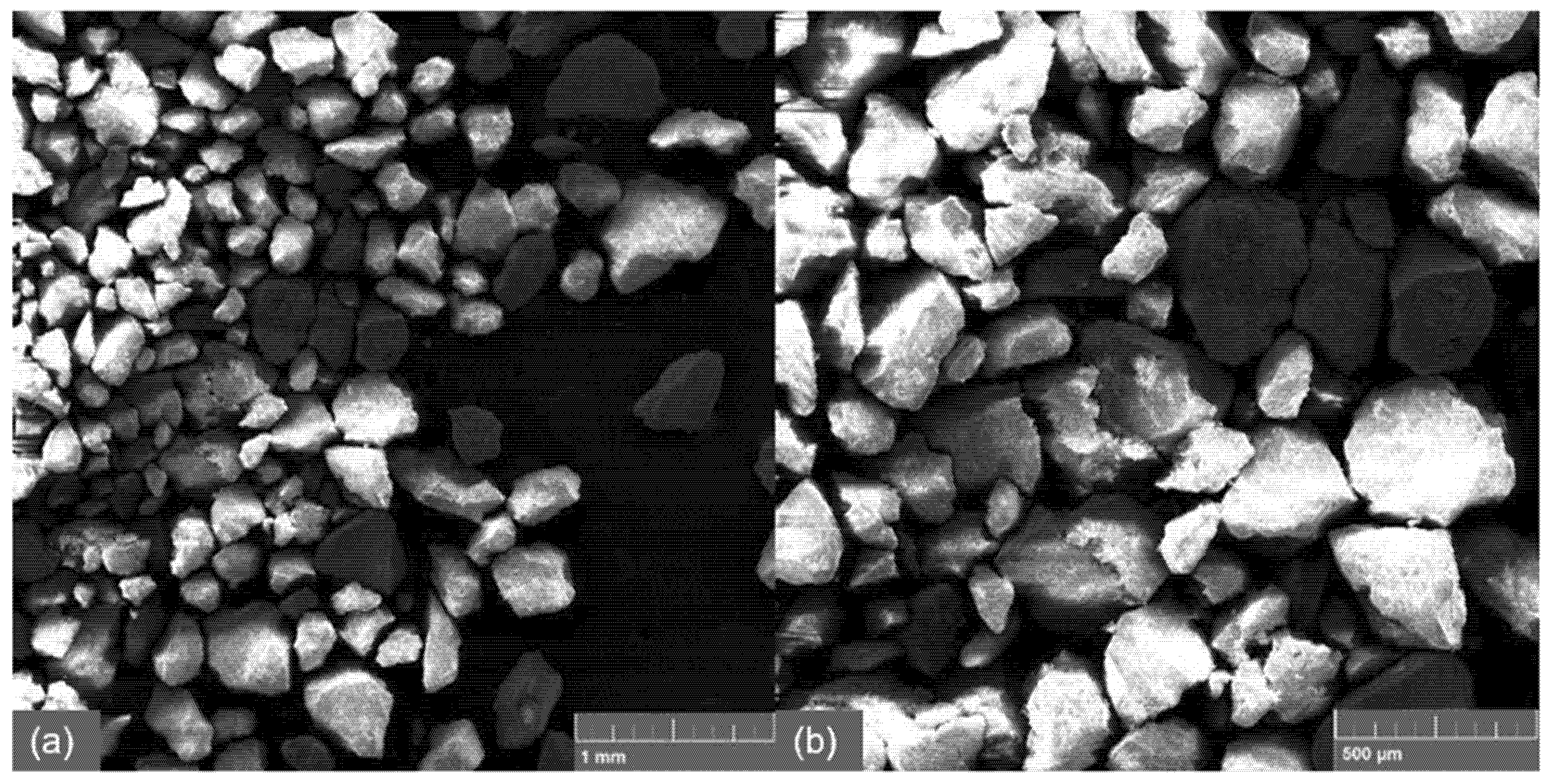
SEM imaging confirms a particle size range between 100 µm and 1 mm (Figure 9). Notably, quartz sand particles are the closest to a spherical shape among the analyzed samples and do not exhibit agglomeration. Unlike CaCO3 particles, sand particles also do not remain suspended in the air “cloud” during sieve analysis. This combination of spherical morphology, high density, and lack of agglomeration allows for the sand particles to respond predictably to inertial lift and Dean forces, concentrating at the expected positions in curved channels. As a result, quartz sand is expected to be the easiest to separate under secondary flow conditions.
Figure 9.
SEM micrographs of pre-separated quartz sand at (a) 50× magnification and (b) 100× magnification.
3.2. Separation Efficiency
Separation efficiency (η) was defined as the fraction of particles successfully collected at the target outlet relative to the total particles introduced into the device, expressed as a percentage. In this study, it was quantified using the normalized powder mass difference (Δ) between Outlet 1 (external stream) and Outlet 2 (internal stream), as measured from the collected powder masses:
where Moutlet1 and Moutlet2 represent the powder masses collected at the respective outlets after processing 100 mL of suspension. Larger values of Δ indicate a more pronounced separation between the outlet streams.
Δ = Moutlet 1 − Moutlet 2
3D-printed spiral channels can achieve passive solid–liquid separation without external fields, with SLA-printed devices often yielding higher mass differences between outlets at lower flow rates [1]. However, the role of channel shape was not explicitly evaluated. In this study, we expand the analysis by comparing devices with circular and square cross-sections while maintaining equal cross-section area, enabling us to isolate and quantify geometry-driven separation behavior.
Table 3, Table 4 and Table 5 summarize the performance of three different separators: SLA (circular cross-section), FFF1 (circular cross-section), and FFF2 (square cross-section), evaluated under varying flow conditions. The SLA device was tested at flow rates of 150, 200, and 250 mL·min−1, while the FFF devices were tested at 250, 300, and 350 mL·min−1. To ensure consistent comparison across devices, all collected powder masses at each outlet were normalized to a standard volume of 100 mL, accounting for the differences in outlet flow distribution. All reported results represent the mean values from five independent separation experiments.
Table 3.
Normalized masses (on the basis of 100 mL) of talc after separation for all separators. Missing values correspond to conditions where the separator could not operate reliably due to clogging or pressure limitations.
Table 4.
Normalized masses (on the basis of 100 mL) of nano CaCO3 after separation for all separators. Missing values correspond to conditions where the separator could not operate reliably due to clogging or pressure limitations.
Table 5.
Normalized masses (on the basis of 100 mL) of quartz sand after separation.
The separation efficiency for the talc sample showed consistent trends across different separator designs. For SLA, the Δ values at 150 mL min−1 to 250 mL min−1 indicate moderate separation, with no clear flow rate dependence. This aligns with our earlier findings where SLA devices performed best at lower flow rates due to the smoother internal surfaces and tighter channel precision. In contrast, FFF1 exhibited increasing Δ values with rising flow rate, reaching the highest Δ (0.1057 g/100 mL) at 350 mL min−1. This suggests internal effects may become more pronounced in FFF-printed devices at higher flow rates, consistent with observations from our prior study. Notably, FFF2, featuring a square cross-section, achieved the highest Δ overall (0.1196 g/100 mL at 300 mL min−1), supporting the hypothesis that sharper corners and altered flow profiles will result in improved particle migration under certain conditions. However, the drop in Δ at 350 mL min−1 for FFF2 indicates a possible disruption of stable flow paths or early onset of turbulent behavior. Additionally, both FFF-printed separators resulted in greater Δ values compared to what we previously reported, even at higher flow rates. This enhancement suggests better performance for the FFF-printed separators, not only in terms of increased responsiveness under standard conditions but also in maintaining their performance under more demanding flow regimes. The ability to sustain a higher Δ value at elevated flow rates highlights the robustness and efficiency of the FFF-based separators and marks a significant design improvement over earlier configurations. These results highlight that both geometry and printing method affect the efficiency of passive separation. The square cross-section showed good potential for improving performance in the intermediate flow regime.
The separation behavior of nano CaCO3 shows pronounced differences compared to talc, primarily due to its smaller particle size and tendency to form agglomerates, which disrupts the ideal dispersion. In SLA, a notable increase in Δ values at 250 mL min−1 (Δ = 0.1721 g/100 mL) suggests improved separation under high shear conditions, likely due to the partial disintegration of agglomerates and subsequent size-dependent migration. FFF2 exhibited a high Δ at 250 mL min−1 (Δ = 0.1412 g/100 mL), followed by a sharp decline at 300 mL min−1 (Δ = 0.0020 g/100 mL), indicating potential instability or localized clogging within the square channels, possibly due to the accumulation of compacted agglomerates. Interestingly, at 350 mL min−1, the Δ value increased again to 0.0739, indicating partial recovery of separation, possibly due to the re-establishment of flow paths or shear-induced rearrangement of agglomerates. During the experiments, FFF-printed devices occasionally experienced clogging, particularly when processing powders with broad size distributions or a tendency to agglomerate. Nano CaCO3, due to its small size and propensity to form loosely bound clusters, caused early blockage in FFF1 and intermittent flow restrictions in FFF2 at higher flow rates (>300 mL min−1). Quartz sand, with larger and irregularly shaped particles, also led to partial clogging in narrow FFF channels, which limited reliable data collection for dome flow conditions. This clogging is attributed primarily to the combination of surface roughness inherent to FFF-printed channels and geometric constraints, which can promote particle adhesion and accumulation. In contrast, SLA-printed devices, featuring smoother channel surfaces, did not exhibit clogging under the same conditions. These observations highlight the influence of both fabrication method and channel geometry on operational reliability and the practical limitations of FFF-based spiral separators for certain particle types.
The results for FFF1 are not presented, as the channel became clogged early in the experiment, preventing reliable data collection. The SLA-printed separator, featuring a modified geometry compared to the two previously reported designs, exhibited a greater Δ value at a flow rate of 250 mL min−1. This improvement suggests that the new geometry contributed to higher efficiency of separation. The observed increase in Δ value highlights the role of geometric optimization in improving fluid–structure interactions within the separator. Combined with the precision of SLA printing, the redesigned structure appears to support more effective separation performance than earlier configurations. In addition, the FFF-printed separator maintained a similar Δ value at 350 mL min−1 as previously observed at 300 mL min−1. This consistency suggests that the FFF design with a rougher channel surface is capable of preserving its separation efficiency even as the flow rate increases, further emphasizing its robustness and suitability for high-flow applications. These findings underscore the challenges in the case of processing cohesive nano-powders in millifluidic geometries.
Quartz sand showed the clearest flow-dependent separation trend among the tested powders. With SLA, the Δ value increased steadily from 0.0316 g/100 mL to 0.2175 g/100 mL as the flow rate increased from 150 mL min−1 to 250 mL min−1. This confirms and strengthens previous findings that SLA-printed spiral devices perform well in separating coarse granular particles when operated at intermediate flow rates. Compared to talc and CaCO3, quartz sand particles are less cohesive and exhibit better-defined trajectories within spiral channels, promoting outlet separation based on inertia. This trend was also reflected in our prior work, where the largest outlet mass differences were observed for quartz sand. The SLA-printed separator, featuring a modified geometry compared to the two previously reported designs, demonstrated a greater Δ value at 250 mL min−1 than previously reported. Notably, earlier designs clogged at this flow rate, preventing data collection. Now, the improved geometry and printing precision enabled successful operation without clogging, allowing us to observe enhanced separation performance at this higher flow rate. However, the absence of data for FFF-printed devices in this table limits comparative interpretation, as both FFF1 and FFF2 clogged during testing with quartz sand. Still, these results support the notion that coarse particles benefit most from inertial effects in spiral designs, particularly when high-resolution fabrication methods like SLA are used to produce smoother, more reliable flow paths.
Table 6 shows the calculated Reynolds numbers for the separators at each flow rate tested. SLA, with a 3 mm diameter circular cross section, exhibits predominantly laminar flow (Re < 2000) across all flow rates, indicating that inertial effects are minimal and particle migration under secondary flow is limited. FFF1, featuring a 2 mm diameter circular cross section but the same cross-sectional area as FFF2, and FFF2, with a square cross section, show higher Reynolds numbers due to their smaller characteristic dimensions and geometry. At flow rates of 300 mL min−1 and above, both FFF1 and FFF2 enter the transitional flow regime (2000 < Re < 4000) where inertial lift and Dean forces become significant, enabling more effective particle focusing and enhancing separation efficiency. Turbulent flow (Re > 4000), which was not reached in these tests, would further disrupt particle trajectories. The effect of flow regime on separation is closely related to particle characteristics. Heavier, spherical particles, such as quartz sand, are more readily focused by Dean forces and efficiently separated at higher Reynolds numbers, whereas low-density, irregularly shaped, or agglomerated particles, such as CaCO3, experience weaker lift and tend to remain dispersed, limiting their separation. However, flow regime and particle properties are not the only factors determining separator performance. In practice, SLA proved highly effective at avoiding clogging, partly due to its smoother surface finish compared to FFF1 and FFF2, which reduces particle adhesion and accumulation. Therefore, while FFF1 and FFF2 may offer better focusing under certain flow conditions, SLA provides practical advantages that enhance reliability and robustness in continuous operation.
Table 6.
Calculated Reynolds numbers for the separators at each flow rate tested.
Unlike the previous study, where most flow conditions remained within the low-laminar regime (Re < 2000), the present study extends analysis into the transitional flow regime, particularly for FFF devices. This wider flow regime allows us to probe inertial separation phenomena under more dynamic conditions and observe potential performance drops or enhancements related to flow instability, especially in square geometries.
3.3. Numerical Validation by COMSOL Simulations
COMSOL Multiphysics simulations were carried out to mirror the experimental conditions and validate the observed separation behavior. Using the Laminar Flow and module, the tested channel geometries and flow rates were reproduced with water as the carrier fluid and particles described with measured particle size distributions (experimental PSD data). The simulations highlighted velocity fields and secondary Dean vortices, which were directly compared to outlet particle distributions, thereby offering a mechanistic explanation for the experimental separation trends.
COMSOL simulations were performed to get mechanistic insight into the particle separation observed experimentally for each powder type. The simulation conditions for each powder were chosen based on the experimental configuration that resulted in the greatest mass difference (Δ) between Outlet 1 and Outlet 2. For talc (Figure 10), the maximum Δ value was obtained in the FFF2 separator with a square cross section and 8 turns at 300 mL min−1. Particles were uniformly released at the inlet and advected by the flow (one-way coupling) under no-slip wall conditions. No-slip wall conditions mean that the fluid velocity at the wall is zero relative to the wall and it is the standard for viscous flows along solid surfaces to ensure realistic modelling of boundary layers and shear near walls. The steady-state velocity field ranged from 0.6 m s−1 to 0.8 m s−1, with reduced velocities along the inner wall. Notably, in the FFF2 separator, a larger fraction of the separator exhibits higher fluid velocities compared to SLA, indicating that particles experience stronger advection and more dynamic mixing throughout the channel. This extended region of higher velocities likely contributes to enhanced separation efficiency, as particles experience stronger outward-directed forces over a greater portion of the channel.
Figure 10.
COMSOL simulations of water velocity magnitude of talc dispersed at 300 mL min−1 in FFF2 separator.
Flow-induced forces directed talc particles toward the outer channel wall, resulting in preferential accumulation at Outlet 2. For flake-like particles such as talc, two dominant orientations are possible: with the wider face or the narrower edge aligned with the flow. This orientation affects hydrodynamic drag and rotational dynamics, resulting in distinct migration tendencies and outlet distributions. While COMSOL simulations capture the laminar flow fields and secondary (Dean) flow structures within the spiral channels, they have several limitations. Particle behaviors such as rotation, orientation-dependent drag, agglomeration, and particle-particle interactions are not included. The simulations also assume smooth walls and neglect transitional or turbulent effects that may occur at higher Reynolds numbers, particularly in FFF-printed devices. Despite these simplifications, the computed velocity fields provide useful mechanistic insight into the flow patterns and regions of higher or lower fluid velocity, which help explain the experimentally observed trends in particle separation.
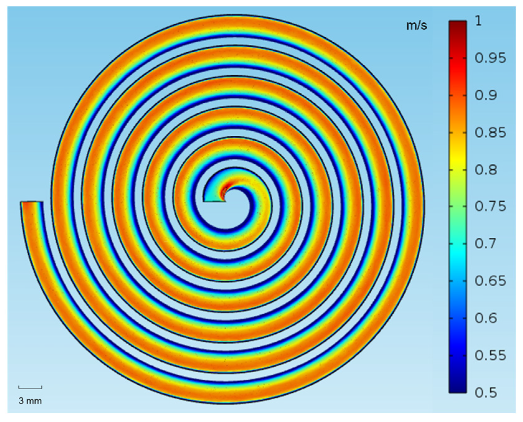
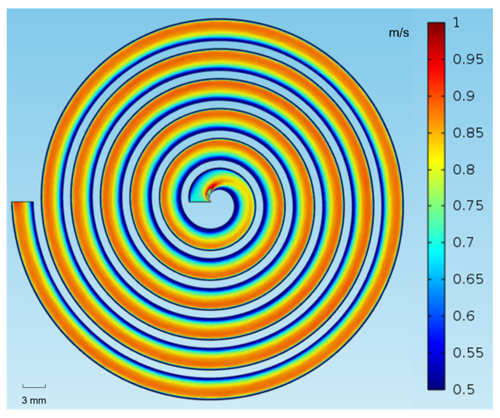
For nano CaCO3 (Figure 11), simulated in SLA with a circular cross section and 6 turns at 250 mL min−1, the velocity field in SLA showed similar characteristics to that in FFF2, but the smaller particle size produced more random outlet distribution, with no clear accumulation at the outer wall. In reality, we would expect some accumulation of particles toward the outer wall, as the fluid velocity is greater near the outer wall and can enhance particle migration in that direction. A key limitation of COMSOL is that it assumes isolated particles and therefore cannot account for agglomeration effects, which in practice would promote clustering and enhance migration toward Outlet 2. Despite this simplification, the simulations remain valuable for identifying baseline flow behavior and predicting how particle size affects dispersion, providing qualitative insight even in the cases where real suspensions exhibit more complex collective interactions.
Figure 11.
COMSOL simulations of water velocity magnitude with nano CaCO3 dispersed at 250 mL min−1 in SLA.
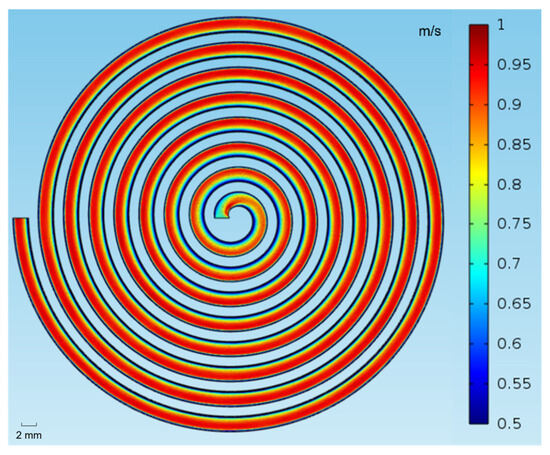
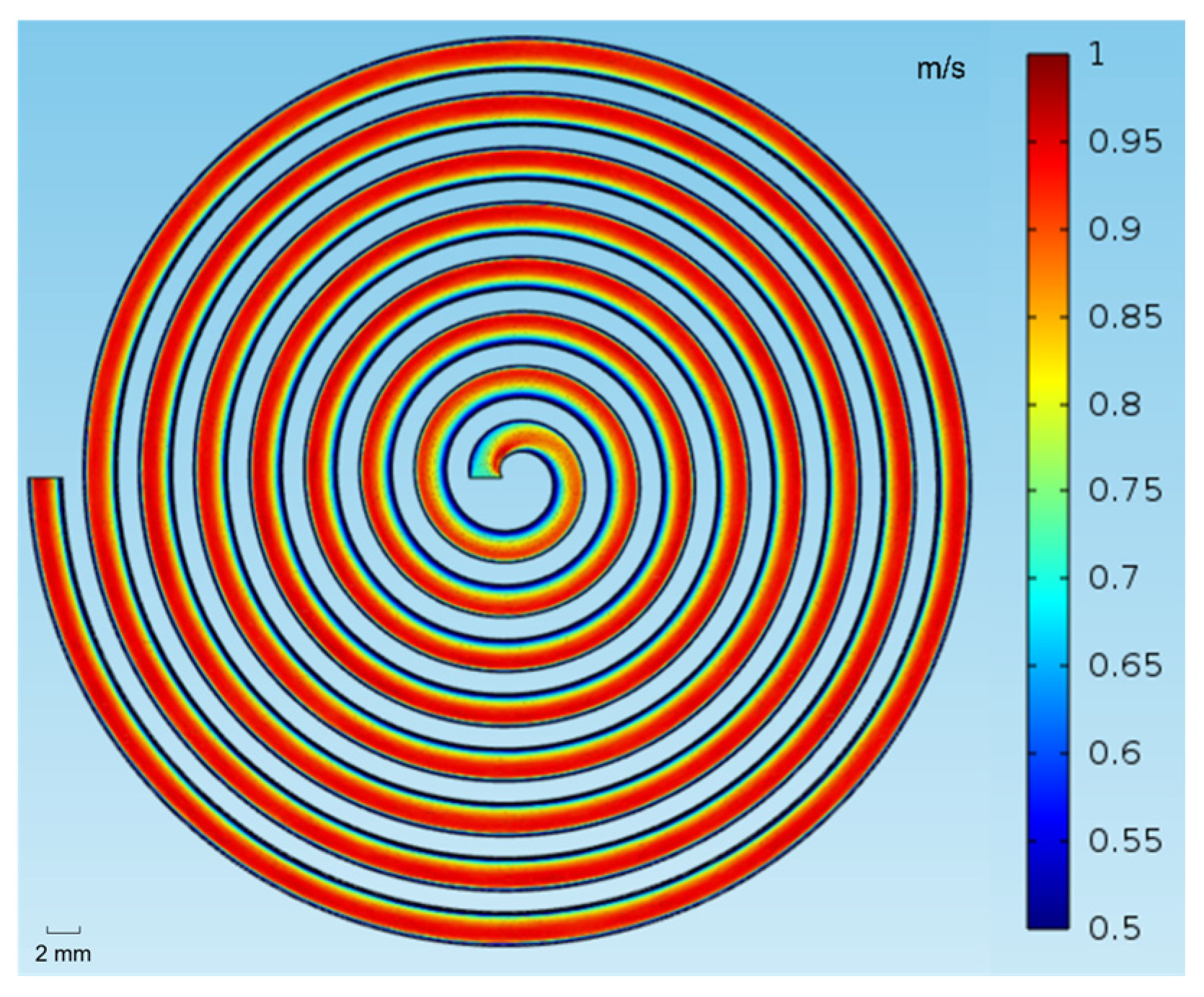
For quartz sand (Figure 12), also in SLA at 250 mL min−1, the flow profile indicates strong outward-directed forces along the outer wall. The larger size and greater inertia of quartz particles make them less sensitive to secondary flow, promoting more pronounced migration toward the outer wall. Among the tested powders, quartz sand is the closest in shape to a sphere and does not readily agglomerate, making COMSOL particularly reliable for predicting its separation behavior. For such near-spherical, non-interacting particles, the flow profile alone provides a good approximation of their likely migration, illustrating the predictive value of COMSOL when orientation and particle–particle interactions are minimal.
Figure 12.
COMSOL simulations of water velocity magnitude with quartz sand dispersed at 250 mL min−1 in SLA.
3.4. Determination of Particle Size Separation Capability
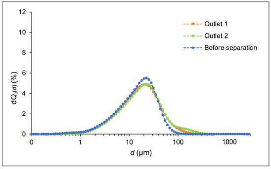
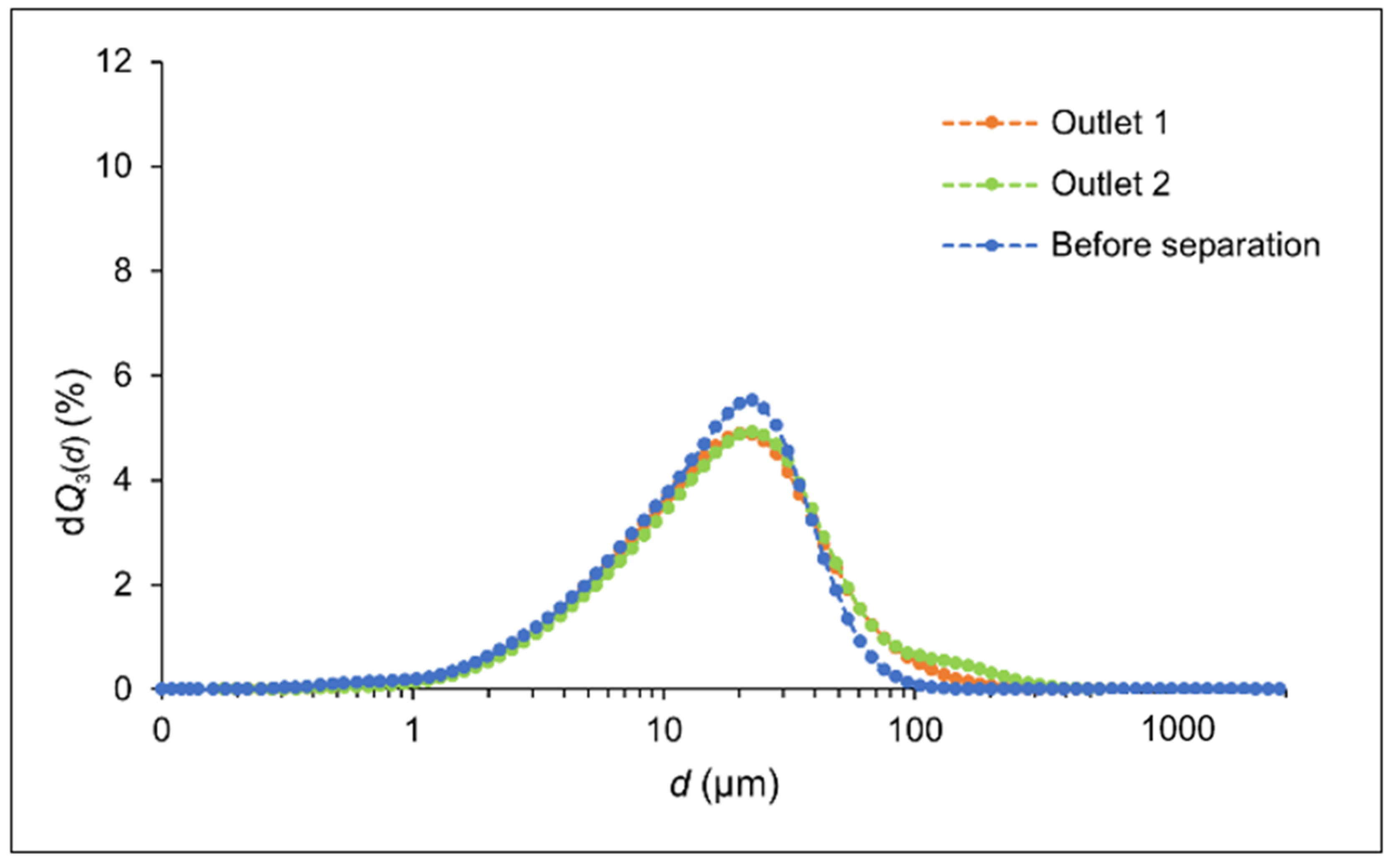
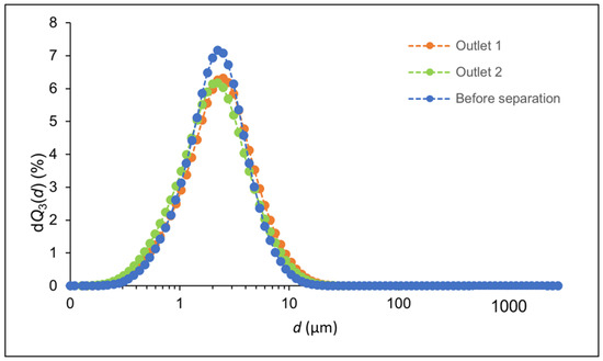
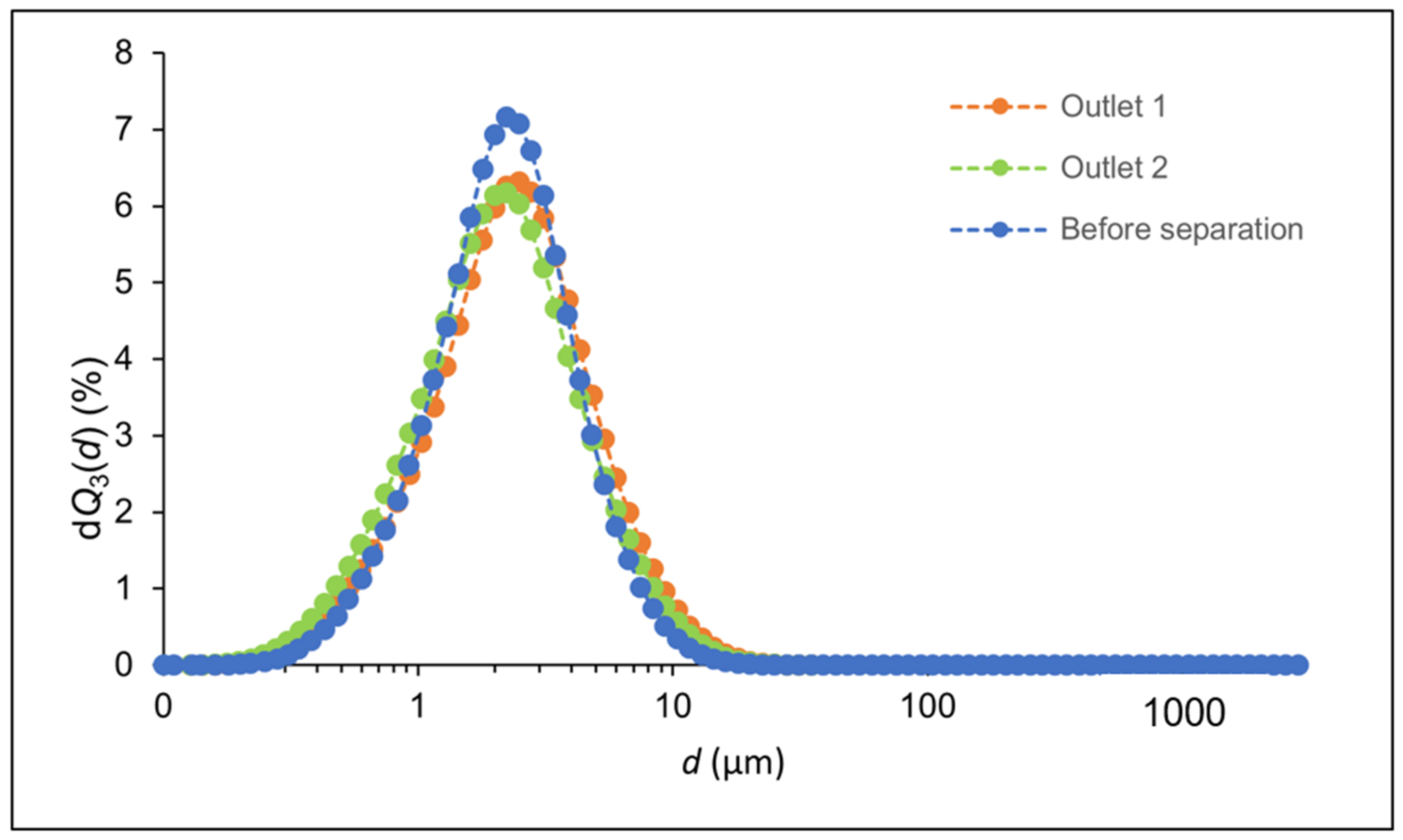
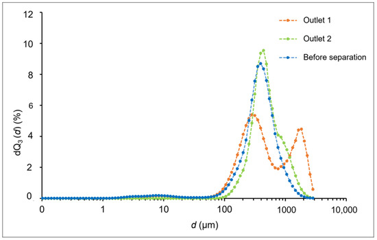
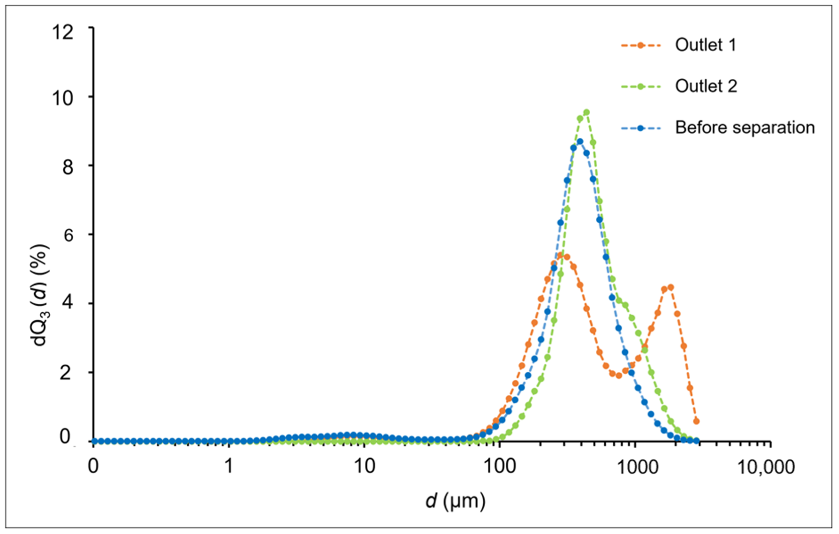
The particle separation performance was assessed through laser diffraction measurement (Figure 13, Figure 14 and Figure 15), highlighting key particle size parameters measured before and after separation (Table 3, Table 4 and Table 5) at two outlets (Outlet 1 and Outlet 2). The most effective separators for each powder type were identified by comparing normalized powder mass differences (Δ). For talc, the best separation performance was achieved using the FFF2 separator at 300 mL min−1 (Δ = 0.1196 g/100 mL). Calcium carbonate was best separated by the SLA separator at 250 mL min−1 (Δ = 0.1721 g/100 mL), and the most effective separation for quartz sand was observed with the SLA separator at the same flow rate (Δ = 0.2175 g/100 mL).
Figure 13.
Graphic view of experimental PSDs of talc before and after separation in FFF2 separator at 300 mL min−1.
Figure 14.
Graphic view of experimental PSDs for nano CaCO3 before and after separation in SLA separator at 250 mL min−1.
Figure 15.
Graphic view of experimental PSDs for quartz sand before and after separation in SLA separator at 250 mL min−1.
Talc occurs as platy, lamellar particles with a high aspect ratio; when dispersed in aqueous media, these platelets may exist as primary flakes, edge-fragmented fines, or as loose aggregates. Laser diffraction reports equivalent spherical diameters and therefore provides only indirect evidence of particle morphology. Nevertheless, comparison of volume- and surface-weighted metrics can reveal morphology-related trends.
Table 7 summarizes the laser diffraction results for talc at a flow rate of 300 mL min−1 in the FFF2 separator. The mode diameter is invariant across samples and indicates that the most frequent equivalent-spherical size class is preserved through the separation. Differences between the median and the surface-area-weighted Sauter mean at the outlets, however, are informative. Before separation, the lower d3,2 relative to d50 indicates a substantial contribution of particles (or particle fragments) with high surface area per unit volume, consistent with talc’s intrinsic platy morphology and/or with the presence of fines or edge fragments. In other words, although the modal class centers at 20 µm, a non-negligible population of small/high-surface-area entities reduces the surface-area-weighted mean. Outlet 1, here the median has shifted downward, d50, indicating enrichment in smaller equivalent diameters at this outlet. The surface-area-weighted mean d3,2 is larger than d50, which implies that the population contains particles whose apparent surface area is small relative to their volume. This pattern is consistent with either compact aggregates (aggregated material behaves as larger, lower-surface-area objects) or oriented platelets whose projected scattering signature under the measurement conditions yields a larger equivalent surface-area-weighted diameter. Thus, Outlet 1 appears to be enriched in smaller-volume particles by number/volume (hence the lower d50, but those particles contribute less to total surface area than would be expected for a population of highly flaky platelets. Outlet 2 presents an intermediate median (17.0 µm) but a markedly smaller d3,2 (13.0 µm), indicating a strong contribution of small, high-surface-area particles. For talc, this is most plausibly explained by an increased fraction of fine platelets or edge fragments (high surface area relative to volume) or by disaggregated primary flakes. Therefore, Outlet 2 is likely enriched in fines and/or individual platelets whose high surface area strongly influences the Sauter mean.
Table 7.
Particle size distribution parameters introduced as characteristic diameters for talc in FFF2 separator at 300 mL min−1.
The separation appears to fractionate particle populations not purely by equivalent spherical size but also by the properties that affect surface-area weighting and scattering (aggregate state, platelet orientation, degree of fragmentation, and surface roughness). Outlet 1 likely contains more compacted or oriented entities (higher d3,2 relative to d50), while Outlet 2 is enriched in fine/high-surface-area platelets (lower d3,2 relative to d50). The invariant dmode indicates the dominant size class remains present throughout, but the proportion of fines and the aggregate state change between outlets.
Nano calcium carbonate (CaCO3) powders, unlike lamellar minerals such as talc, are composed of near-equiaxed particles (spherical to rhombohedral morphologies) that readily agglomerate in aqueous suspensions. When characterized by laser diffraction, particles are treated as equivalent spheres, meaning that morphology has a less pronounced effect on dmode, d50, and d3,2 values compared to platy or fibrous materials. Table 8 summarizes the laser diffraction results for CaCO3 at a flow rate of 250 mL min−1 in the SLA separator. The mode diameter remains constant at 2.5 µm across all conditions, indicating no shift in the dominant size class. Both the median diameter and the surface-area-weighted vary minimally between 2.3 and 2.4 µm (d50) and 1.9 and 2.0 µm (d3,2). The close agreement between d50 and d3,2 is characteristic of materials composed of near-spherical or isotropic particles, where surface area scales consistently with volume. The small difference between d50 and d3,2 indicates negligible particle shape effects, meaning that separation is not morphology-dependent. These changes in particle size distribution indicate that the SLA separator produces a slight enrichment of larger particle agglomerates at Outlet 1, while Outlet 2 retains a particle size distribution similar to the original sample.
Table 8.
Particle size distribution parameters introduced as characteristic diameters for nano CaCO3 in SLA separator at 250 mL min−1.
Quartz sand consists of angular, irregular particles with sharp edges and facets. Such morphologies deviate strongly from the spherical assumption in laser diffraction analysis and can produce large discrepancies between volume-based and surface-area-weighted size descriptors.
Table 9 summarizes the laser diffraction results for quartz sand at a flow rate of 250 mL min −1 in the SLA separator. The mode diameter shifts significantly across conditions: from 354.8 µm before separation to 281.8 µm at Outlet 1 and 446.7 µm at Outlet 2. This indicates that Outlet 1 is enriched in finer particles, whereas Outlet 2 preferentially contains coarser fractions. The median diameter follows a similar trend, with values increasing from 384.9 µm (before separation) to 415.3 µm (Outlet 1) and 444.3 µm (Outlet 2). The close agreement of d50 with dmode confirms that the separation effectively fractionates quartz particles according to size, with Outlet 1 skewed toward finer classes and Outlet 2 toward coarser ones. The surface-area-weighted mean diameter, however, shows exceptionally high values (827.7 µm before separation, 1777.9 µm at Outlet 1, and 1038.0 µm at Outlet 2). This divergence between d50 and d3,2 is a clear indicator of irregular particle morphology. For angular quartz grains, roughness, edges, and non-sphericity yield disproportionately high apparent surface-area contributions, amplifying the calculated d3,2. The particularly elevated value at Outlet 1 suggests that the finer fraction is enriched in highly irregular, possibly fractured particles with extreme surface-to-volume ratios.
Table 9.
Particle size distribution parameters introduced as characteristic diameters for quartz sand in SLA separator at 250 mL min−1.
The quartz sand data demonstrate that the separation process yields a fine fraction (Outlet 1) and a coarse fraction (Outlet 2), as reflected by dmode and d50. The anomalously high d3,2 values, especially in the fine fraction, reflect the angular, rough morphology of quartz grains, underscoring the limitations of interpreting laser diffraction data under the spherical-particle assumption.
Compared to the work by Yeh et al. [29], which demonstrated efficient spiral microchannels for continuous small particle separation using planar geometries and optimized Dean flow profiles, this study expands the geometric design space to include both circular and square cross-sections of equal area fabricated by additive manufacturing. Yeh et al. reported separation efficiencies up to 99.7% and separation purities of 95–99% at flow rates around 0.4 mL min−1, highlighting the trade-off between throughput and size selectivity in planar designs. Due to differences in particle sizes and system geometry, the separation purities reported in this study cannot be directly compared to those of Yeh et al., although their results remain useful for benchmarking flow rates and operational windows. In contrast, the present results show that square cross-sections enhance inertial effects and mass-based separation at intermediate flow rates, particularly for microfluidic devices produced via FFF. This enhancement can be attributed to the flow dynamics inherent to square cross-sections. Square channels promote stronger secondary flows and inertial forces compared with planar geometries, which facilitate lateral migration of particles and improve mass-based separation. Importantly, our devices maintain effective separation even at higher flow rates than those reported by Yeh et al., demonstrating an expanded operational window and increased throughput, both critical for practical applications in chemical analysis, biomedical diagnostics, and particle sorting.
The ability of FFF fabrication to precisely realize square geometries, which may be challenging with conventional planar designs, further contributes to the observed performance improvements. Overall, the combination of enhanced inertial effects, robust mass-based separation, and scalable additive manufacturing allows our devices to outperform traditional planar designs in both efficiency and operational flexibility. Meanwhile, the study by Sierra Agudelo et al. [30] introduced scalable, low-cost 3D-printed spiral separators with a channel radius of 0.42 cm for cell and bead separation, emphasizing the effect of channel height and dual-spiral integration on size-based sorting performance. Building on this, the current work further demonstrates how fabrication method and internal channel geometry jointly affect the separation of heterogeneous powder suspensions, with SLA-printed devices offering smoother flow and reduced clogging at high throughput. This study’s findings can be meaningfully compared to those of Jeon et al. [31], who engineered deformation-free plastic spiral inertial microfluidic devices for high-throughput Chinese hamster ovary (CHO) cell clarification. Jeon et al. specifically addressed the limitations introduced by PDMS soft-lithography, showing that channel deformation could lead to clogging or loss of separation fidelity under the conditions of intense flow. By switching to rigid, 3D-printed plastic spirals, they achieved robust, clog-free operation with sustained inertial focusing at faster flow rates, demonstrating the advantages of precision fabrication and material choice for continuous separation applications. In the present study, analogous challenges with clogging and reproducibility were observed, especially for FFF-printed PETG spiral separators when processing fine or cohesive powders at transitional flow rates. However, the use of SLA printing with rigid photopolymer resins allowed the fabrication of high-resolution, deformation-resistant and smoother channels, resulting in more consistent separation outcomes even at elevated throughputs. Furthermore, while Jeon et al. validated their plastic spirals primarily for cell clarification, the current work extends these benefits to passive solid–liquid separation of polydisperse suspensions, showing that geometric optimization and rigid fabrication methods work synergistically to enhance separator reliability. This parallel highlights the broader significance of deformation-free and high-fidelity channel production, whether for biological cells or mixed powders, in advancing scalable, field-free microfluidic separation technologies. Collectively, these comparisons underscore the importance of channel geometry and fabrication fidelity in tuning passive microfluidic separators, while positioning the results here as a meaningful advancement in tailoring, customization and scalability of 3D-printed systems for suspension processing.
Unlike these previous studies, this work integrates COMSOL Multiphysics simulations to qualitatively simulate real flow behavior. Although direct particle trajectories were not simulated, the velocity field distributions obtained computationally reproduce critical aspects of the experimental system, providing strong evidence for the mechanisms underlying the observed separation trends. Specifically, these simulations visualize the emergence of secondary flows, Dean vortices, that arise due to the channel curvature. The resulting interplay between axial flow and secondary Dean flows generates complex velocity gradients that influence particle migration throughout the cross-section. Dean-induced transverse drag and inertial lift forces establish characteristic positions for suspended particles, shaping the separation performance observed experimentally. Such computational analysis, which cannot readily be achieved through experiments alone, constitutes a novel contribution, reinforcing the reliability of the experimental findings and demonstrating that COMSOL simulations can be a valuable tool for predicting flow behavior and optimizing new channel designs prior to fabrication.
This study expands upon previous work [1], which demonstrated the feasibility of 3D-printed spiral separators fabricated via SLA and FFF for passive solid–liquid separation. That investigation included two SLA devices with square and circular cross sections, respectively, and one FFF device with a circular cross section, highlighting the effect of flow rate and manufacturing method on the performance of separation. The present study broadens its scope through the inclusion of a wider range of flow rates and more systematically varied channel geometries. The selection of SLA and FFF as fabrication methods was guided by their complementary capabilities in terms of geometric fidelity, achievable resolution, and manufacturing flexibility, consistent with established decision-support frameworks for additive manufacturing process selection [32]. Specifically, the device was set to include an additional SLA separator with a circular cross section and two FFF devices featuring circular and square cross sections, respectively, while maintaining a constant cross-sectional area across FFF designs. This approach enables a more controlled assessment of the role of channel shape on separation efficiency. The results confirm and refine earlier findings, demonstrating that subtle geometric differences can significantly affect inertial forces and particle migration, particularly under intermediate flow conditions. These observations underscore the significance of both fabrication method and channel geometry in the optimization of passive separation systems.
While the study provides valuable insights into geometry-driven separation in 3D-printed spiral channels, several limitations have to be acknowledged. Devices fabricated via FFF exhibited notable variability in performance, primarily due to the surface roughness, inconsistent internal features, and a higher tendency for clogging, particularly under higher flow rates or with finer particles. This influenced flow reproducibility and limited the operational range for some FFF prototypes. Additionally, the use of nano-sized calcium carbonate introduced challenges related to agglomeration. Despite sonication and dilution steps, nanoparticle clusters likely persisted, affecting both suspension homogeneity and separation behavior. This may explain the lack of clear trends in particle size distributions between inlets and outlets, especially at low flow rates. These limitations underscore the trade-offs between rapid prototyping via low-cost methods and the precision required for reproducible, fine-scale separations.
4. Conclusions
This study builds upon our previous work by systematically introducing and comparing square and circular cross-sections of equal area, and by evaluating separation performance across a wider range of flow rates (150 mL min−1 to 350 mL min−1). These additions isolate the geometric effects of the internal channel cross-section and reveal the effect of flow conditions on separation performance, especially in devices printed via FFF. These additions allowed us to isolate the effects of channel geometry and flow conditions on separation, particularly in FFF-printed devices. For talc, the maximum outlet mass difference (Δ) of 0.1196 g/100 mL was observed in the FFF2 (square) separator at 300 mL min−1, whereas the SLA (circular) device achieved Δ = 0.0770 g/100 mL at 250 mL min−1. Nano CaCO3 showed the highest separation in SLA at 250 mL min−1 with Δ = 0.1721 g/100 mL, while FFF2 exhibited Δ = 0.1412 g/100 mL at the same flow rate. Quartz sand separation was most effective in SLA at 250 mL min−1, with Δ = 0.2175 g/100 mL.
The results demonstrate that square cross-sections enhance inertial effects at intermediate flow rates, especially in FFF devices, resulting in higher Δ values compared to circular channels. SLA devices consistently performed well with coarser powders like quartz sand due to the smoother internal surfaces and more precise channel smoothness, which support stable secondary flows and particle segregation. COMSOL Multiphysics simulations were used to visualize velocity fields and secondary flows, providing computational insight into the flow patterns within the spiral channels and supporting the experimental observations.
While all devices showed some capacity to redistribute particles by mass, particle size distributions remained broadly similar across outlets, indicating that separation is primarily driven by inertial and hydrodynamic forces rather than strict size selectivity. Overall, these findings underscore the significance of careful geometric and fabrication design in optimizing separators for suspensions, and highlight the promise of low-cost, customizable, tailored and field-free systems for scalable applications in materials processing, environmental monitoring, and biomedical diagnostics. FFF-induced clogging and nanoparticle agglomeration highlight key areas for improvement in device design and experimental methodology. FFF-induced clogging and nanoparticle agglomeration highlight key areas for improvement in device design and experimental methodology.
Author Contributions
M.-P.M.: Conceptualization, Data curation, Formal analysis, Investigation, Methodology, Validation, Visualization, Writing—original draft, Writing—review and editing. E.F.: Formal analysis, Validation, Writing—original draft, Writing—review and editing. K.Ž.: Data curation, Methodology, Validation, Writing—review and editing. D.V.: Conceptualization, Funding acquisition, Methodology, Supervision, Validation, Visualization, Writing—review and editing. All authors have read and agreed to the published version of the manuscript.
Funding
This work was supported by the Croatian Science Foundation under the projects HRZZ-DOK-NPOO-2023-10-1144, HRZZ-DOK-2021-02-5999, and HRZZ-IP-2022-10-8004.
Institutional Review Board Statement
Not applicable.
Informed Consent Statement
Not applicable.
Data Availability Statement
The data are available upon reasonable request from the corresponding authors.
Conflicts of Interest
The authors declare no conflicts of interest.
References
- Marković, M.-P.; Žižek, K.; Soldo, K.; Sunko, V.; Zrno, J.; Vrsaljko, D. 3D Printed Microfluidic Separators for Solid/Liquid Suspensions. Appl. Sci. 2024, 14, 7856. [Google Scholar] [CrossRef] [Scilit]
- Zhao, H.; Zhang, Y.; Hua, D. A Review of Research Progress in Microfluidic Bioseparation and Bioassay. Micromachines 2024, 15, 893. [Google Scholar] [CrossRef] [Scilit] [PubMed]
- Hwang, S.H.; Gonzalez-Suarez, A.M.; Stybayeva, G.; Revzin, A. Prospects and Opportunities for Microsystems and Microfluidic Devices in the Field of Otorhinolaryngology. Clin. Exp. Otorhinolaryngol. 2021, 14, 29–42. [Google Scholar] [CrossRef] [Scilit]
- Rainville, P. Microfluidic LC–MS for Analysis of Small-Volume Biofluid Samples: Where We Have Been and Where We Need to Go. Bioanalysis 2010, 3, 1–3. [Google Scholar] [CrossRef] [Scilit]
- Di Carlo, D. Inertial Microfluidics. Lab Chip 2009, 9, 3038–3046. [Google Scholar] [CrossRef] [Scilit]
- Cetin, B.; Li, D. Dielectrophoresis in Microfluidics Technology. Electrophoresis 2011, 32, 2410–2427. [Google Scholar] [CrossRef] [Scilit]
- Alnaimat, F.; Dagher, S.; Mathew, B.; Hilal-Alnqbi, A.; Khashan, S. Microfluidics Based Magnetophoresis: A Review. Chem. Rec. 2018, 18, 1596–1612. [Google Scholar] [CrossRef] [Scilit] [PubMed]
- Ebrahimi, A.; Icoz, K.; Didarian, R.; Shih, C.; Tarim, E.A.; Nasseri, B.; Akpek, A.; Cecen, B.; Bal-Ozturk, A.; Güleç, K.; et al. Molecular Separation by Using Active and Passive Microfluidic Chip Designs: A Comprehensive Review. Adv. Mater. Interfaces 2024, 11, 2300492. [Google Scholar] [CrossRef] [Scilit]
- Zhang, T.; Di Carlo, D.; Lim, C.T.; Zhou, T.; Tian, G.; Tang, T.; Shen, A.Q.; Li, W.; Li, M.; Yang, Y.; et al. Passive Microfluidic Devices for Cell Separation. Biotechnol. Adv. 2024, 71, 108317. [Google Scholar] [CrossRef] [Scilit]
- Ching, T.; Li, Y.; Karyappa, R.; Ohno, A.; Toh, Y.-C.; Hashimoto, M. Fabrication of integrated microfluidic devices by direct ink writing (DIW) 3D printing. Sens. Actuators B Chem. 2019, 297, 126609. [Google Scholar] [CrossRef] [Scilit]
- Beauchamp, M.J.; Nordin, G.P.; Woolley, A.T. Moving from millifluidic to truly microfluidic sub-100-μm cross-section 3D printed devices. Anal. Bioanal. Chem. 2017, 409, 4311–4319. [Google Scholar] [CrossRef] [Scilit]
- Waheed, S.; Cabot, J.M.; Macdonald, N.P.; Lewis, T.; Guijt, R.M.; Paull, B.; Breadmore, M.C. 3D Printed Microfluidic Devices: Enablers and Barriers. Lab Chip 2016, 16, 1993–2013. [Google Scholar] [CrossRef] [Scilit]
- Forjan, E.; Marković, M.P.; Kassal, P.; Vrsaljko, D. Development and Characterization of Litmus-Based pH Sensor Films for Real-Time Monitoring in 3D Printed Microreactor Channels. J. Sol-Gel Sci. Technol. 2025, 115, 1–16. [Google Scholar] [CrossRef] [Scilit]
- Marković, M.-P.; Kassal, P.; Vrsaljko, D. Design and Fabrication of a pH Sensor-Coated Microreactor System. IEEE Sens. J. 2024, 24, 32090–32097. [Google Scholar] [CrossRef] [Scilit]
- Husna, A.; Ashrafi, S.; Tomal, A.A.; Tuli, N.T.; Rashid, A.B. Recent Advancements in Stereolithography (SLA) and Their Optimization of Process Parameters for Sustainable Manufacturing. Hybrid Adv. 2024, 7, 100307. [Google Scholar] [CrossRef] [Scilit]
- Ruiz, C.; Kadimisetty, K.; Yin, K.; Mauk, M.G.; Zhao, H.; Liu, C. Fabrication of Hard–Soft Microfluidic Devices Using Hybrid 3D Printing. Micromachines 2020, 11, 567. [Google Scholar] [CrossRef] [Scilit] [PubMed]
- Roibu, A.; Udroiu, R.; Abreu-Jaureguí, C.; Silvestre-Albero, J.; Andronic, L. Wavelength-Dependent Activity Screening of Reduced Titania for Photocatalytic Degradation of Imidacloprid in Batch and Flow-Mode. J. Environ. Chem. Eng. 2024, 12, 112752. [Google Scholar] [CrossRef] [Scilit]
- Enders, A.; Preuss, J.-A.; Bahnemann, J. 3D Printed Microfluidic Spiral Separation Device for Continuous, Pulsation-Free and Controllable CHO Cell Retention. Micromachines 2021, 12, 1060. [Google Scholar] [CrossRef] [Scilit]
- Zhao, Q.; Yuan, D.; Zhang, J.; Li, W. A Review of Secondary Flow in Inertial Microfluidics. Micromachines 2020, 11, 461. [Google Scholar] [CrossRef] [Scilit] [PubMed]
- Nivedita, N.; Ligrani, P.; Papautsky, I. Dean Flow Dynamics in Low-Aspect Ratio Spiral Microchannels. Sci. Rep. 2017, 7, 44072. [Google Scholar] [CrossRef] [Scilit] [PubMed]
- Filippa, L.; Trento, A.; Álvarez, A.M. Sauter Mean Diameter Determination for the Fine Fraction of Suspended Sediments Using a LISST-25X Diffractometer. Measurement 2012, 45, 364–368. [Google Scholar] [CrossRef] [Scilit]
- Solovev, S.A.; Soloveva, O.V. Study of the Influence of the Mean Particle Diameter Choice and the Fractions Number on the Quality of Fluidized Bed Numerical Simulation. Processes 2024, 12, 2528. [Google Scholar] [CrossRef] [Scilit]
- Mohammadimehr, A.; Rodríguez-Villarreal, A.I.; López Martínez, J.A.; Casals-Terré, J. Review: Impact of microfluidic cell and particle separation techniques on microplastic removal strategies. J. Agric. Food Res. 2024, 16, 101124. [Google Scholar] [CrossRef] [Scilit]
- Farahinia, A.; Zhang, W.; Badea, I. Recent developments in inertial and centrifugal microfluidic systems along with the involved forces for cancer cell separation: A review. Sensors 2023, 23, 5300. [Google Scholar] [CrossRef] [Scilit] [PubMed]
- Amani, A.; Shamloo, A.; Vatani, P.; Ebrahimi, S. Particles focusing and separation by a novel inertial microfluidic device: Divergent serpentine microchannel. Ind. Eng. Chem. Res. 2022, 61, 13845–13856. [Google Scholar] [CrossRef] [Scilit]
- Ozyilmaz, E.; Ilis, G.G. Design and Performance Analysis of Spiral Microchannels for Efficient Particle Separation Using Inertial Microfluidics. Micromachines 2025, 16, 349. [Google Scholar] [CrossRef] [Scilit]
- Thimmaraju, M.K.; Trivedi, R.; Hemalatha, G.; Thirupathy, B.; Billah, A.M. Microfluidic Revolution and Its Impact on Pharmaceutical Materials: A Review. Mater. Today Proc. 2023; in press. [CrossRef] [Scilit]
- Aryal, P.; Hefner, C.; Martinez, B.; Henry, C.S. Microfluidics in Environmental Analysis: Advancements, Challenges, and Future Prospects for Rapid and Efficient Monitoring. Lab Chip 2024, 24, 1175–1206. [Google Scholar] [CrossRef] [Scilit]
- Yeh, P.Y.; Dai, Z.; Yang, X.; Bergeron, M.; Zhang, Z.; Lin, M.; Cao, X. An efficient spiral microchannel for continuous small particle separations. Sens. Actuators B Chem. 2017, 252, 606–615. [Google Scholar] [CrossRef] [Scilit]
- Sierra Agudelo, J.N.; Subirada, F.; Hendriks, M.; Trujillo, R.R.; Samitier, J. Low-cost 3D printed inertial flow microfluidic devices for cellular isolation in liquid biopsies. Front. Lab Chip Technol. 2023, 2, 1175668. [Google Scholar] [CrossRef] [Scilit]
- Jeon, H.; Kwon, T.; Yoon, J.; Han, J. Engineering a deformation-free plastic spiral inertial microfluidic system for CHO cell clarification in biomanufacturing. Lab Chip 2022, 22, 272–285. [Google Scholar] [CrossRef] [Scilit]
- Bikas, H.; Koutsoukos, S.; Stavropoulos, P. A decision support method for evaluation and process selection of additive manufacturing. Procedia CIRP 2019, 81, 1107–1112. [Google Scholar] [CrossRef] [Scilit]

Disclaimer/Publisher’s Note: The statements, opinions and data contained in all publications are solely those of the individual author(s) and contributor(s) and not of MDPI and/or the editor(s). MDPI and/or the editor(s) disclaim responsibility for any injury to people or property resulting from any ideas, methods, instructions or products referred to in the content. |
© 2026 by the authors. Licensee MDPI, Basel, Switzerland. This article is an open access article distributed under the terms and conditions of the Creative Commons Attribution (CC BY) license.