


Abstract
Constant power loads (CPLs) introduce nonlinear voltage–current characteristics that can restrict the feasible operation of power-electronic converters. This paper presents a nonlinear steady-state framework for characterizing the feasible operating region of a single-phase PWM current-source converter (PWM-CSC) supplying a CPL. The averaged converter model is transformed into the synchronous reference frame and reduced to a nonlinear algebraic system that explicitly relates converter states, modulation variables, and active–reactive power demands. The resulting equilibrium set is mapped onto the P–Q and P–Q–m spaces to identify admissible operating points and modulation requirements. The numerical procedure evaluated 50,000 operating points with a 100% convergence rate, an average solution time of 4.168 ms per point, and residual norms below . Time-domain simulations in PSIM v9 validated representative operating points across the feasible region, with maximum deviations of approximately 0.83% in active power and 0.74% in reactive power relative to the prescribed references. Simulations also showed degraded voltage regulation near the feasibility boundary and loss of regulation for demands outside the identified region. The proposed approach provides a quantitative tool for feasibility-aware operation of PWM-CSCs supplying CPLs.
1. Introduction
Modern smart grids and microgrids increasingly rely on distributed energy resources (DERs), photovoltaic generation, and battery energy storage systems (BESSs) to support the transition toward low-carbon power systems. As [1] points out, coordinating these assets requires balancing economic targets with strict technical boundaries, including voltage drops, network losses, and flow limits. Consequently, power-electronic interfaces have become the backbone of these networks, managing the continuous power exchange between local loads, storage units, and distributed generation [2].
This integration introduces a distinct operational challenge at the converter stage: a growing share of connected equipment is driven by tightly regulated power stages, causing them to behave as constant power loads (CPLs) [3]. Unlike standard passive loads, CPLs draw more current as voltage drops to keep power constant, introducing a negative incremental impedance [4]. Because of this behavior, a power setpoint requested by a supervisory controller may look optimal on paper yet prove physically unattainable for the feeding converter once its modulation, voltage, and current limits are factored in [5].
Such constraints are especially critical in low-voltage scenarios—such as single-phase residential setups, islanded microgrids, and battery-based systems—where converter operating margins are inherently tight [6]. In these environments, identifying the exact active and reactive power combinations a converter can reliably sustain is important before applying higher-level control schemes. Explicitly mapping this feasible operating region effectively bridges the gap between system-level power scheduling and converter-level hardware limits [7].
Conventionally, single-phase voltage source converters (VSCs) have been utilized to supply CPLs through cascaded control structures, typically comprising inner current control loops and outer voltage or power regulation loops [8]. While these architectures are effective under nominal conditions, they often rely on aggressive current limiting, saturation mechanisms, and conservative control tuning to preserve stability when supplying CPLs [9]. Consequently, system performance may be compromised under substantial disturbances, parameter variations, or rapid fluctuations in power demand.
In this context, single-phase current source converters (CSCs) emerge as a compelling alternative. Due to their inherent current-regulating properties, CSCs offer intrinsic protection against overcurrent conditions and can demonstrate enhanced robustness when interfacing with demanding or nonlinear loads [10]. When combined with appropriate output filtering and control strategies, CSCs have the capacity to operate as controlled voltage sources, thereby enabling their utilization in grid-forming or stand-alone applications [11]. Notwithstanding the aforementioned advantages, the operational limits of single-phase CSCs supplying CPLs have not yet been systematically characterized [12].
From this perspective, a fundamental converter-level problem is determining whether a prescribed active–reactive power demand corresponds to a model-based equilibrium region [13]. This feasibility question precedes the subsequent assessment of local or dynamic stability and becomes particularly relevant under CPL operation [14], where modulation limits, power balance conditions, and nonlinear load characteristics jointly constrain the admissible operating set [15].
The operating region is defined as the set of operating points at which a converter can supply or absorb active and reactive power, while maintaining physical and dynamic sustainability under steady-state conditions [7]. For converters supplying CPLs, this region becomes particularly relevant, as it explicitly reveals the boundaries beyond which stable operation cannot be guaranteed [16]. Furthermore, the interaction between the converter control variables (e.g., modulation index and phase angle) and the nonlinear characteristics of CPLs has the potential to significantly distort or reduce the feasible operating region, thereby increasing the risk of instability [17].
Several control approaches, including proportional–integral regulators, passivity-based control, model predictive control, and adaptive schemes, have been proposed to guarantee asymptotic stability and improve dynamic performance under parameter variations and load disturbances [18]. More recently, research efforts have extended toward nonlinear stability analysis using Lyapunov-based and port-Hamiltonian frameworks, providing systematic methodologies to establish stability conditions and enhance robustness in CSC-operated power conversion systems [19,20].
When CPLs are considered, the stability problem becomes significantly more challenging because the load exhibits a negative incremental impedance characteristic that may destabilize the converter–load interaction [21]. Existing studies have mainly investigated this phenomenon in VSC systems, where CPL-induced instabilities have been extensively analyzed through impedance-based methods, bifurcation analysis, and nonlinear control techniques [22,23,24].
Although mathematical modeling of PWM current-source converters is a mature research topic, the characterization of feasible operating regions under CPL conditions remains largely unexplored. Existing studies have primarily focused on converter modeling, control design, or operating region analysis for three-phase systems and conventional loads, whereas little attention has been devoted to determining the active–reactive power combinations that can be physically achieved by single-phase PWM-CSCs while maintaining voltage regulation and satisfying modulation constraints. This issue is particularly relevant in emerging applications such as single-phase microgrids, renewable-energy interfaces, and power-electronics-dominated networks, where CPLs are common and the available operating margins are often severely restricted.
The present paper proposes a systematic methodology for the development and analysis of the operating region of a single-phase current source converter supplying a constant power load, commencing from its mathematical model. The proposed approach integrates dynamic modeling, steady-state analysis and numerical continuation techniques, facilitating the identification of feasible operating points in the P–Q plane and the characterization of critical boundaries associated with loss of feasibility and degradation in control.
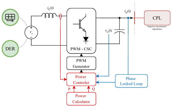
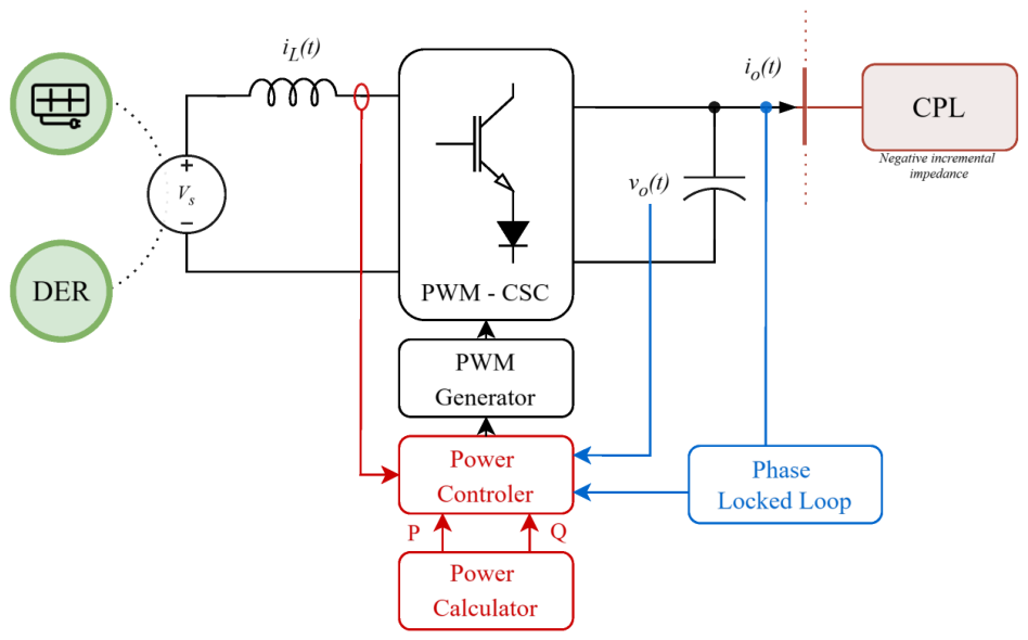
As illustrated in Figure 1, the PWM-CSC is supplied by a DC-side current source associated with a DER, whose current is regulated through a DC-link inductor. In the alternating current (AC) domain, the converter facilitates the delivery of power to a CPL via an output capacitor, thereby modulating the voltage waveform at the point of common coupling. The power exchange between the converter and the load is governed by a controller that generates the modulation references for the pulse-width modulation (PWM) generator, while a phase-locked loop (PLL) provides phase information required for synchronization and power calculation. This is used to generate an equivalent orthogonal signal. The information is used to calculate active and reactive power, as well as dq-based signal processing.
Figure 1.
Structure of a single-phase PWM-CSC supplying a constant power load.
In contradistinction to passive loads, the CPL enforces a fixed power demand, resulting in a nonlinear voltage–current relationship and a negative incremental impedance characteristic [25]. This behavior introduces intrinsic limitations on the range of power references that the converter can safely track, even in circumstances where modulation and current constraints are not explicitly violated.
Motivated by the challenges introduced by constant power loads and the limited availability of operating-region studies for single-phase PWM current-source converters, this work seeks to address the following research questions:
- How can the feasible steady-state operating region of a single-phase PWM-CSC supplying a CPL be mathematically characterized?
- What are the admissible active and reactive power combinations that can be achieved while maintaining a prescribed output voltage and respecting converter modulation constraints?
- How do the resulting operating boundaries relate to the dynamic behavior of the converter when operating inside, near, and outside the feasible region?
Answering these questions enables the construction of operating maps that provide insight into converter limitations, feasible power-transfer capabilities, and the practical implications of CPL-induced constraints.
The primary contributions of this study can be outlined as follows:
- A dynamic and steady-state mathematical model of a single-phase current source converter supplying a constant power load has been developed.
- The operating region in the active–reactive power plane has been analytically formulated, with modulation constraints and CPL behavior being explicitly accounted for.
- The present study investigates the influence of CPL parameters on the shape and size of the operating region, thereby revealing critical feasibility boundaries imposed by modulation constraints and CPL power demands.
- The theoretical analysis is validated through time-domain simulations, demonstrating the correspondence between operating region boundaries and degraded dynamic performance.
The proposed operating-region analysis is particularly relevant for practical power-electronic systems where tightly regulated loads are supplied through current-source conversion stages. Examples include islanded microgrids, renewable-energy conversion systems, battery energy storage interfaces, electric vehicle charging stations, and industrial power supplies feeding electronic loads with constant-power characteristics. In such applications, knowledge of the feasible operating region is essential for preventing unstable operating conditions associated with the negative incremental impedance of CPLs. Furthermore, the derived operating boundaries can support converter design, controller tuning, and supervisory energy-management strategies by identifying admissible active and reactive power references before real-time operation.
The remainder of this paper is organized as follows. Section 2 of this text delineates the topology of the single-phase current source converter, in conjunction with the control strategy that has been adopted. In Section 3, the dynamic and steady-state mathematical modeling of the system is presented, including the representation of the constant power load. Section 4 of this text delineates the operating region in the P–Q plane, whilst also providing a comprehensive description of the numerical procedure that is utilized in order to compute said region. In Section 5, an analysis is conducted on the properties of the obtained operating region and on its sensitivity to CPL parameters. Section 6 provides a validation of the proposed approach through the presentation of simulation results. Finally, Section 7 and Section 8 conclude the paper and outline directions for future research.
2. Single-Phase PWM-CSC and Control Scheme
This section details the single-phase PWM-CSC topology, which interfaces a distributed energy resource with a CPL. The system consists of a regulated DC current source, a DC-link inductor, a PWM switching bridge, and an AC-side output filter. The CSC converts the DC current into a controlled AC waveform, while the filter attenuates switching harmonics and shapes the output voltage. Unlike voltage source inverters, the CSC inherently limits output current, offering protection against over-current conditions. The load is characterized as a CPL, whose negative incremental impedance can challenge system stability. This topology provides the foundation for mathematically modeling the system and deriving its feasible operating region in the active–reactive power plane.
Single-PhasePWM-CSC Topology and Voltage-Oriented Operation
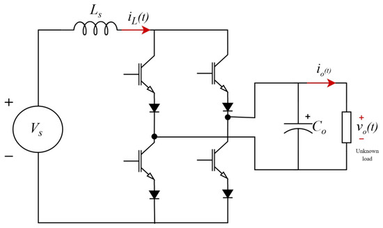
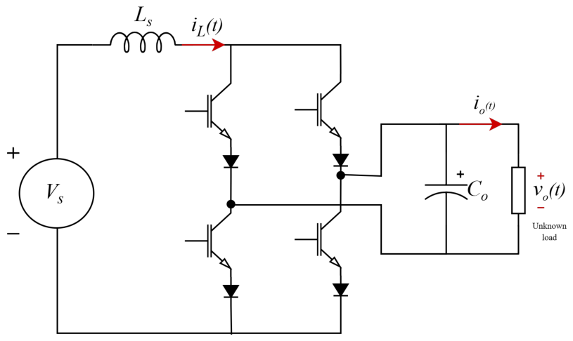
The single-phase PWM-CSC considered is employed to interface a DC energy source with an AC-side load, as illustrated in Figure 2. The converter is supplied by a regulated DC source, which may be derived from renewable energy systems or energy storage units through an appropriate front-end stage. A DC-link inductor is included to enforce the current-source nature of the converter and ensure continuous current operation.
Figure 2.
Electrical topology of the single-phase PWM current source converter supplying a constant power load.
The power stage consists of a PWM-controlled switching bridge that converts the DC current into an AC current waveform. Through suitable modulation, the converter injects a controlled current into the output filter, enabling the synthesis of a sinusoidal voltage at the load terminals. Unlike voltage-source converters, the CSC naturally limits the output current, providing an inherent degree of protection against over-current conditions and making it attractive for applications involving demanding or nonlinear loads [26].
On the AC side, an output filter attenuates switching harmonics and shapes the voltage delivered to the load. The filter dynamics play a fundamental role in the interaction between the converter and the connected load, directly affecting both the steady-state operating points and the dynamic response of the system [27,28].
The converter supplies a constant power load (CPL), whose power demand remains approximately constant despite variations in the terminal voltage. This behavior introduces a nonlinear voltage–current relationship and results in a negative incremental impedance characteristic, which can significantly influence the converter operating limits and the existence of admissible equilibrium points. Consequently, the feasible operating region is determined not only by the converter modulation constraints but also by the power demand imposed by the CPL.
The analysis developed in this paper adopts a voltage-oriented operating principle. The converter is required to maintain a sinusoidal output voltage reference of the form , where and denote the voltage magnitude and phase angle, respectively. Under sinusoidal steady-state conditions, the active and reactive power exchanged with the load depend on the interaction between the converter modulation variables and the CPL characteristics.
In the PWM-CSC, the modulation process establishes a direct relationship between the DC-side current and the AC-side variables. The modulation index m determines the magnitude of the injected fundamental component, while the modulation phase angle defines its orientation with respect to the output voltage. Therefore, the pair constitutes the key set of variables governing the achievable steady-state operating points.
3. Mathematical Modeling of the Single-Phase PWM-CSC
This section develops the mathematical framework required to analyze the steady-state behavior and operating limits of the single-phase PWM current source converter supplying a constant power load. A dynamic model is first derived in the stationary reference frame, capturing the fundamental coupling between the DC-side inductor, the AC-side output capacitor, and the modulation process. To facilitate steady-state analysis and control design, this model is subsequently transformed into a synchronous rotating reference frame, where sinusoidal quantities appear as constant values. The resulting dynamic representation explicitly reveals the cross-coupling between the d and q axes introduced by the frame rotation. Finally, by imposing steady-state conditions, the dynamic equations reduce to a set of nonlinear algebraic constraints that, together with the constant power load characteristics, define the admissible operating points of the system.
3.1. Dynamic Model in the Time Domain
The dynamic behavior of the single-phase PWM-CSC supplying a constant power load is first described in the stationary reference frame. In consideration of the topology illustrated in Figure 2, the system dynamics are governed by the DC-side inductor and the AC-side output capacitor. The resulting averaged model can be expressed as (1) [29].
where denotes the DC-side inductor current, is the output capacitor voltage, represents the load current, m is the modulation signal, and and correspond to the DC source voltage and series resistance, respectively. This model explicitly captures the coupling between the modulation process and the energy exchange between the DC and AC sides of the converter.
Although the model in (1) provides an intuitive description of the converter dynamics, its direct use for control design and steady-state analysis becomes cumbersome when sinusoidal steady-state operation and power exchange are of interest [30]. For this reason, it is customary in both single-phase and three-phase systems to transform the system variables from a stationary reference frame into a synchronous rotating reference frame [31]. This transformation allows sinusoidal steady-state quantities to be represented as constant values, thereby simplifying the analysis of operating points and power flow.
In this study, an equivalent synchronous reference frame is adopted, defined by the angular position , where is the angular frequency and is a phase offset typically provided by a PLL. The transformation from the stationary frame to the synchronous frame is defined as [32]:
with the transformation matrix given by:
When differentiating a signal expressed in the synchronous reference frame, two distinct contributions arise. Taking the time derivative of yields [33]:
The first term accounts for the rotation of the reference frame, while the second term reflects the actual variation of the signal magnitude in the stationary frame [34]. By explicitly evaluating the derivative of the transformation matrix, the expression can be rewritten as (5).
The rotational term introduces cross-coupling between the d and q axes, which can be expressed as:
This coupling is a fundamental characteristic of synchronous reference frame modeling and must be explicitly accounted for in control and observer design. Notably, even if the stationary-frame variable is constant, its representation in the rotating frame may still exhibit time variation due to the frame rotation.
Applying this formulation to the output voltage dynamics in (1), the capacitor voltage expressed in the synchronous reference frame satisfies:
where denotes the DC-link current, while and correspond to the direct- and quadrature-axis components of the load current, respectively. The modulation process is parameterized by a modulation index , which represents the normalized amplitude of the fundamental switching function generated by the PWM-CSC. Physically, m determines the fraction of the available DC-link current that is transferred to the AC side and can therefore be interpreted as a measure of the converter modulation effort. The quantities and represent the direct- and quadrature-axis modulation components, defined as , . The orientation of this modulation action is determined by the angle , leading to the synchronous-frame modulation components.
Then, the output voltage and modulation signals can be expressed as
The average product over one fundamental period is then
Expanding the expression yields
Using the well-known trigonometric averages and , the averaged product becomes
The instantaneous product also contains a twice-line-frequency component. More explicitly,
where
The amplitude of this component is
The averaging procedure removes the twice-line-frequency component inherent to single-phase power conversion. The DC-link current appearing in the steady-state formulation must be interpreted as its average value rather than as an exactly constant instantaneous current.
Considering the DC-link dynamics, the amplitude of the corresponding second-harmonic current ripple can be approximately estimated as
For the nominal parameters adopted in this work, , , , and , Equation (16) gives
Thus, the maximum estimated second-harmonic ripple amplitude for is approximately , corresponding to a peak-to-peak variation of approximately . This ripple is not represented in the steady-state equilibrium map, which is intended to characterize the average operating point.
Finally, combining the DC-side dynamics with the AC-side dynamics in the synchronous reference frame [16], the complete dynamic model of the system is obtained as
This dynamic representation forms the foundation for the steady-state analysis and operating region formulation developed in the following sections. In particular, it explicitly reveals the coupling between modulation, synchronous-frame voltage dynamics, and load behavior, which is essential for understanding the feasibility and operating limit imposed by CPLs.
3.2. Steady-State Model
To characterize the feasible operating points of the single-phase PWM current source converter, the system is analyzed under the assumption of sinusoidal steady-state operation. Under this condition, all electrical variables are periodic with constant amplitude and frequency, and their representation in the synchronous reference frame becomes time-invariant.
When sinusoidal steady-state operation is established, the time derivatives of the synchronous variables vanish. Consequently, the dynamic model derived in Section 3.1 can be reduced to a set of algebraic equations by imposing . Applying these conditions to the dynamic equations yields:
These expressions describe the steady-state balance between the DC-side current, the modulation action, and the synchronous components of the AC-side voltages and currents. Importantly, the rotational coupling terms introduced by the synchronous reference frame remain present, reflecting the intrinsic interaction between the d and q axes even under steady-state conditions [35].
In the synchronous reference frame, the modulation signal is characterized by its magnitude and phase angle, which directly determine the orientation and amplitude of the injected current vector [36]. As a result, the steady-state values of the synchronous currents can be expressed as functions of the modulation index m and the modulation phase angle . These control variables, together with the DC-side current and the system parameters, fully determine the steady-state operating point of the converter.
To close the steady-state formulation, the load behavior must be incorporated. For a constant power load, the active and reactive power absorbed at the converter output are defined as (20) [37],
and are enforced through the algebraic constraints:
By combining the steady-state converter equations with the power constraints imposed by the load, the system is ultimately reduced to a set of nonlinear algebraic equations linking the synchronous voltages, load currents, modulation index, and modulation phase angle. This nonlinear system defines the admissible steady-state solutions of the converter–load system.
The existence and multiplicity of solutions of this algebraic system determine the feasible operating points of the single-phase CSC. These solutions form the basis for the operating region analysis developed in the following section, where the set of admissible steady-state points is mapped onto the active–reactive power plane and interpreted in terms of feasibility and stability.
4. Formulation of the Operating Region in the P–Q Plane
The operating region is a set of all active and reactive power pairs P–Q that satisfy the steady-state algebraic equations derived in Equation (19) for admissible values of the control variables and system parameters [15].
4.1. Power Definition in the Synchronous Reference Frame
Under sinusoidal steady-state operation, the instantaneous active and reactive power exchanged between the converter and the load can be conveniently expressed in the synchronous reference frame [38]. Using the synchronous voltage and current components at the load interface, the active and reactive power are defined as in (20).
These expressions provide a direct mapping between the steady-state electrical variables and the power quantities of interest, enabling the representation of converter operation in the P–Q plane.
4.2. Steady-State Algebraic System Parameterized by Control Variables
As established in Section 3, imposing sinusoidal steady-state conditions transforms the dynamic model of the converter–load system into a set of nonlinear algebraic equations. In the present formulation, the steady-state behavior is parameterized by two control variables: the modulation index m and the modulation phase angle .
The modulation signal is decomposed into its synchronous components as:
which determines the orientation and magnitude of the injected current vector in the synchronous reference frame. For given values of m and , the steady-state equations describe the balance between the DC-side power, the modulation action, and the AC-side power delivered to the load.
The resulting algebraic system links the DC inductor current, the synchronous components of the load current and voltage, and the modulation parameters. Due to the nonlinear nature of the constant power load and the multiplicative coupling introduced by modulation, this system is inherently nonlinear and may admit multiple or no solutions depending on the selected control parameters.
4.3. Numerical Construction of the Operating Region
The operating region is obtained through a systematic numerical procedure based on a parametric sweep of the control variables. The modulation index m is varied within a predefined admissible range, while the phase angle is swept over a full electrical period. For each pair , the steady-state algebraic equations are solved using a nonlinear numerical solver.
Under the fixed-voltage condition considered in this study, the operating region is constructed from the explicit steady-state mapping derived above. For numerical verification the original nonlinear equations were evaluated using the fsolve function available in MATLAB R2025b, which implements iterative methods for solving systems of nonlinear equations. For each pair of modulation parameters (), the solver computes the corresponding steady-state variables by minimizing the residual of the algebraic equations derived in Section 3.2. Appropriate convergence tolerances were imposed to ensure numerical consistency of the obtained solutions. To further verify the validity of the computed operating points, selected cases were implemented and tested through time-domain simulations in PSIM v9, allowing comparison between the steady-state analytical solutions and the dynamic response of the PWM current-source converter model.
The parameters listed in Table 1 establish the nominal case study used to demonstrate the proposed operating-region methodology. This approach is fully parameterized, meaning it can be adapted to different converter designs simply by updating the corresponding electrical quantities.
Table 1.
Nominal electrical parameters of the single-phase PWM-CSC adopted for the operating-region analysis and time-domain simulations.
Only solutions satisfying a prescribed convergence tolerance are retained as feasible operating points. For each valid solution, the corresponding active and reactive power are computed using the expressions defined in (20).
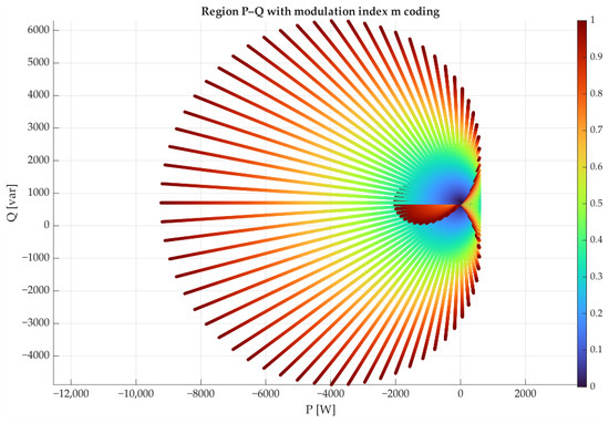
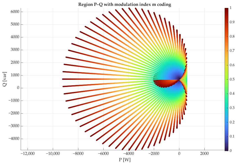
The operating region shown in Figure 3 exhibits a strongly asymmetric structure in the P–Q plane, with a significant extension toward negative active power values. This behavior reflects the intrinsic characteristics of the current-source topology under constant voltage operation, where the converter can more easily operate in power absorption regimes.
Figure 3.
Operating region of the single-phase PWM current source converter in the P–Q plane.
The color-coded modulation index reveals that low values of m are concentrated near the central region, whereas higher modulation levels are required as the operating point moves away from the origin, particularly along trajectories with large apparent power demand. This distribution highlights the increasing control effort needed to sustain operation near the boundaries of the feasible region.
The region shown in Figure 3 does not represent a conventional converter capability curve, such as those commonly used for synchronous machines or grid-connected voltage source converters. Instead, it corresponds to the set of feasible equilibrium points obtained from the nonlinear steady-state equations of the PWM-CSC under fixed operating conditions V and and modulation constraints .
The shape of the region is not determined by thermal ratings or current limits, but rather by the existence of physically admissible solutions satisfying the converter equilibrium equations. The pronounced asymmetry toward negative active power values originates from the voltage conversion ratio imposed in the analysis, since the output voltage is maintained at while the DC-side source voltage is fixed at V. Under these conditions, only specific combinations of the modulation index m and modulation angle satisfy the steady-state constraints, leading to a non-symmetric distribution of feasible operating points in the P–Q plane.
This behavior can be further understood from the steady-state relationships
together with the DC-side equilibrium condition
Since is significantly larger than , the dependence of the active power on the modulation component becomes inherently asymmetric. As a result, the feasible operating region extends predominantly toward negative active-power values, reflecting the equilibrium constraints imposed by the converter and the prescribed output-voltage condition.
Changes in , , and directly modify the attainable active-power range and the asymmetry of the P–Q region, whereas and mainly influence the reactive-power balance through the capacitor current. In contrast, does not appear explicitly in the steady-state equilibrium equations because ; therefore, its main influence is associated with the transient response rather than with the nominal steady-state feasibility boundary. Accordingly, different converter parameter sets will lead to quantitatively different operating regions, while the proposed formulation and numerical procedure remain unchanged.
The modulation index associated with each operating point is used as a color-coded parameter, enabling a direct visualization of how the control effort varies across the operating region. This representation reveals not only the shape of the feasible region in the P–Q plane but also the distribution of modulation levels required to reach different operating points.
4.4. Convexity of the Steady-State Equilibrium Region
To analyze the convex hull analytically as a representation of the operating-region boundary, let and denote the direct- and quadrature-axis modulation components, respectively. The admissible modulation domain corresponds to the unit disk,
Under the fixed output voltage, the DC-link current can be expressed directly from the steady-state DC-side equation. Introducing the auxiliary constants:
the current and the corresponding active and reactive power can be written in compact form as
These expressions provide a useful geometric interpretation of the equilibrium region. For every fixed value of x, Equation (25) restricts the quadrature modulation component to
The reactive power associated with a given value of x lies within an interval centered at . The upper and lower limits of this interval can be expressed as
Thus, the convexity of the P–Q equilibrium region can be assessed by examining the curvature of the boundary function H with respect to the active power P. The outer boundary is generated by the monotonic branch
for which
Therefore, is monotonic over this branch, and H can be treated as a single-valued function of P. Evaluating its curvature yields
Within the considered branch, the denominator of Equation (32) is positive. The numerator is a monotonically increasing function of x and therefore reaches its maximum at . At this point,
It follows that, whenever ,
Hence, the upper boundary is concave, whereas the lower boundary is convex. The region enclosed between these two curves is therefore convex and can be written as
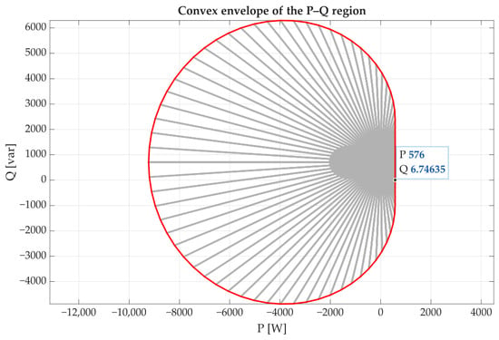
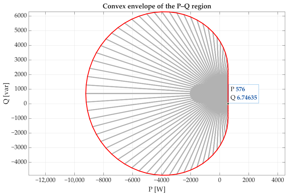
For the nominal operating conditions considered, , and the convexity condition is satisfied. For the model-based equilibrium set considered here, the convex hull shown in Figure 4 does not introduce additional points that are absent from the original steady-state region. It therefore provides an equivalent geometric representation of the equilibrium boundary rather than an approximation that enlarges the set.
Figure 4.
Convex envelope of the model-based P–Q equilibrium region.
4.5. Boundary Extraction and Region Interpretation
The convex envelope shown in Figure 4 highlights the effective boundaries of the feasible operating region. While the original set of solutions presents a dense distribution of operating points, the convex hull provides a simplified geometric interpretation of the maximum admissible active and reactive power combinations. This representation is particularly useful for identifying the operational limits of the converter and for defining admissible setpoints in supervisory control applications.
From a modulation perspective, operating points located near the boundary require modulation indices closer to their admissible limit. Therefore, the distance to the boundary provides an indication of the remaining modulation margin and should be interpreted strictly in terms of steady-state feasibility.
The resulting operating region is non-uniform and direction-dependent, which can be attributed to the combined effects of modulation constraints, DC-side limitations, and the nonlinear behavior of the constant power load. In particular, the region is skewed toward negative active power values, indicating that the converter exhibits different feasibility margins depending on the direction of power flow.
Note that the physically admissible region is subject to change and heavily relies on the particular converter implementation. The equilibrium region , defined in Equation (35), represents the model-based steady-state operating set under the modulation constraint .
For a specific converter implementation, additional electrical and thermal constraints must be imposed. The corresponding physically admissible region can be defined as
For a unidirectional DC source, the additional condition must also be imposed. If the DC port is bidirectional, negative values of may be admissible, subject to the corresponding source-current rating.
Under the fixed-voltage condition, the steady-state active-power balance can be written as
Equation (37) is a concave quadratic function of the DC-link current. Its maximum positive value occurs at , which yields
For the nominal parameters and , the model therefore predicts (Figure 4).
The same power-balance equation also explains the large negative-power branch observed in the complete equilibrium map. Negative active power does not have a unique physical interpretation and must be examined together with the DC-link current direction.
If , then , which corresponds to power being returned to the DC port. Such operation is only possible if the DC source or front-end interface is reversible.
When , the resistive dissipation exceeds the power provided by the DC source. In this case, the negative AC-side power corresponds to additional power entering the converter from the AC port and being dissipated in the series resistance.
5. Analysis of the Operating Region
This section analyzes the properties of the operating region obtained from the steady-state formulation of the converter–load system. The objective is to interpret the feasibility and structure of the admissible operating points in terms of the modulation variables and the active–reactive power exchange. The analysis begins with a feasibility assessment in the plane for a prescribed CPL demand, which provides insight into the admissible combinations of modulation index and phase angle required to satisfy the imposed power constraints. Subsequently, the study is extended to the P–Q plane, where feasibility regions and modulation effort distributions are evaluated in order to characterize the operating limits of the single-phase PWM-CSC under CPL conditions.
It should be emphasized that the objective of the simulation stage is not to compare control strategies, but to verify whether the operating points predicted by the nonlinear steady-state analysis are dynamically realizable. The adaptive PI–PBC controller is adopted as a validation mechanism because of its previously reported suitability for single-phase PWM-CSC operation. Nevertheless, the feasible P–Q operating boundaries obtained in this work are determined by the converter topology, modulation constraints, fixed output voltage condition, and CPL characteristics. Therefore, while different controllers may modify transient indicators such as settling time, overshoot, and damping, they do not alter the physical feasibility boundary of the converter–load system. Operating points outside the identified region remain infeasible regardless of the selected controller.
5.1. Steady-State CPL Constraints and Incremental Behavior
The operating region of the single-phase PWM-CSC is characterized by the active and reactive power demanded at the converter output. For a CPL, these quantities remain fixed regardless of small variations in the terminal voltage. As a result, the load current must adjust to the terminal voltage to meet the required power demand.
In the synchronous reference frame, the active and reactive power absorbed by the load are given by (20). Under the assumed fixed output-voltage condition, the reference frame is aligned with the output voltage vector such that and . Accordingly, the load power equations reduce to:
Thus, for a prescribed power demand , the corresponding equilibrium load-current components are
These expressions define the current required from the converter to sustain the target operating point under the specified voltage condition. It is important to distinguish this steady-state relationship from the incremental behavior that characterizes a CPL. At the nominal voltage , a passive load designed to absorb the same active and reactive power would exhibit identical equilibrium current components. Therefore, the equilibrium point alone does not differentiate between a CPL and an equivalent passive load. This difference becomes clear when examining voltage perturbations around the equilibrium point. For the active-power component of the CPL, the current depends on the terminal voltage according to:
Linearization around the nominal operating voltage gives
and therefore the incremental conductance is:
For comparison, an equivalent resistive load absorbing the same active power at the nominal voltage can be defined as:
Its current–voltage relationship is:
which yields the incremental conductance
Thus, although both loads exhibit the same equilibrium current at , their incremental responses have opposite signs. For , the CPL features a negative incremental conductance, whereas the equivalent resistive load features a positive one. Consequently, this negative incremental impedance is a local dynamic property driven by voltage perturbations around the equilibrium point, rather than the mechanism that dictates the steady-state feasibility boundary. Under the fixed-voltage condition, the specified power demand can be directly incorporated into the converter equilibrium equations by substituting the corresponding load-current components. The resulting steady-state system is
These equations establish the equilibrium constraints associated with a target power demand. For a given pair , feasibility requires the existence of converter variables that simultaneously satisfy the DC-side power balance, the AC-side current requirements, the fixed output-voltage condition, and the admissible modulation range.
As the requested active or reactive power increases, the necessary equilibrium current components also rise, which typically demands a larger modulation effort and progressively reduces the available modulation margin. The steady-state operating boundaries derived in the next section are governed by the converter equilibrium equations, the specified output voltage, the demanded active and reactive power, and the physical modulation constraints.
The negative incremental impedance of the CPL does not directly dictate this equilibrium boundary. It becomes relevant when examining the local dynamic response around a feasible operating point. The operating-region analysis developed in this work focuses on steady-state feasibility, whereas a formal assessment of CPL-induced damping or stability effects requires a dedicated dynamic or small-signal analysis.
5.2. Operating Region in the P–Q–m Space Under Constant Voltage Operation
To further characterize the operating capability of the single-phase PWM-CSC, the feasible steady-state solutions are represented in the three-dimensional P–Q–m space. The synchronous voltage components are imposed as and , which corresponds to aligning the synchronous reference frame with the output voltage vector.
Once the steady-state currents are obtained (19), the complex output voltage and current are defined as
and the apparent power is computed as
Therefore, the active and reactive power associated with each operating point are
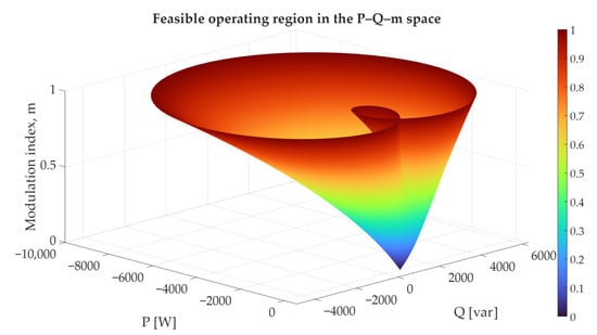
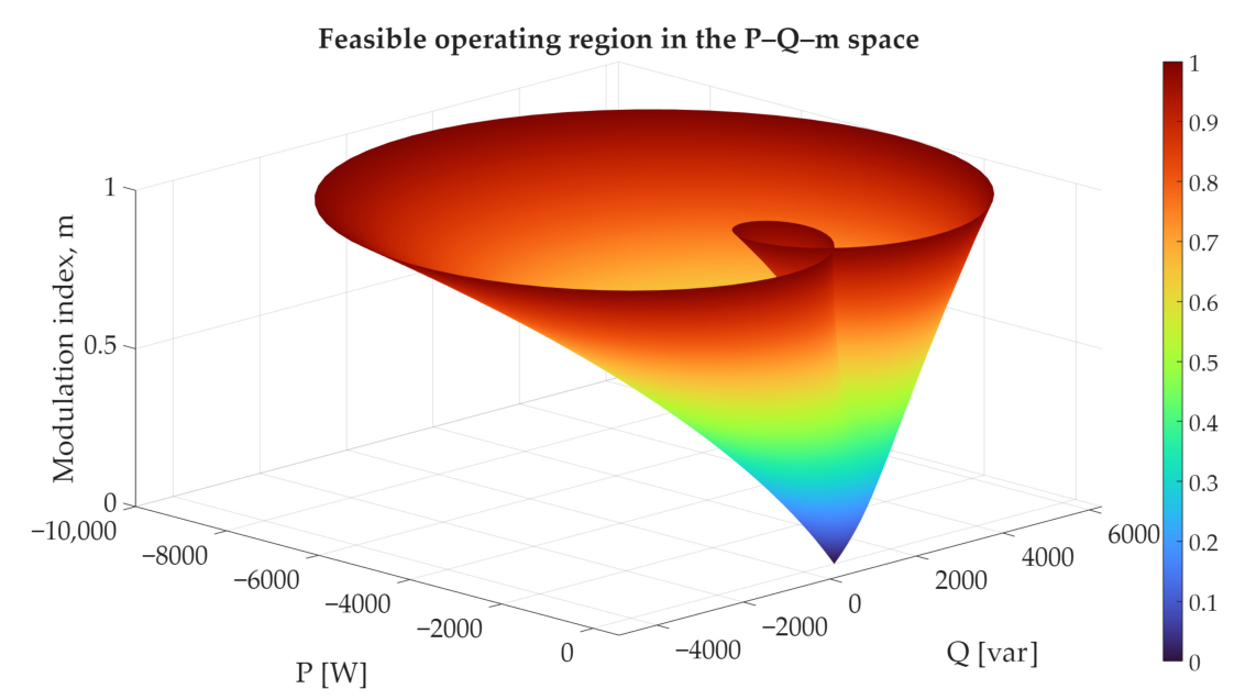
The resulting surface, shown in Figure 5, represents the operating range of the converter in the P–Q–m space. Each point on the surface corresponds to a steady-state solution generated by a specific pair under the fixed output voltage condition. The modulation index increases as the operating point moves away from the low-power region, indicating that larger active and reactive power demands require higher modulation effort.
Figure 5.
Three-dimensional operating range of the single-phase PWM-CSC in the P–Q–m space under fixed output voltage operation.
A notable characteristic of the obtained surface is the apparent overlap in the central region. From an algebraic standpoint, it can be deduced that disparate combinations of m and may result in analogous active and reactive power values. In the physical implementation of the PWM-CSC, the admissible solution is effectively unique because the converter is constrained by the imposed voltage orientation, current directionality, modulation limits, and closed-loop operating conditions. It is the solution that is compatible with the physical converter dynamics and the selected control action that is realized in practice.
This three-dimensional representation is a complementary addition to the two-dimensional P–Q operating region, by means of an explicit linkage between each feasible operating point and the modulation index required to achieve it. The P–Q–m surface provides a direct interpretation of the control effort associated with each region of operation and facilitates the identification of zones where the converter operates in closer proximity to modulation saturation.
The operating region is represented in terms of the output active and reactive power; the obtained solutions are intrinsically linked to the converter input variables. From the DC-side steady-state Equation (49), the inductor current can be expressed as
Every feasible point in the P–Q–m space is associated with a unique DC-side operating condition. The corresponding input power can be estimated as:
while the converter losses are approximately given by
The feasible operating region can also be interpreted as the set of active and reactive power combinations that satisfy both the AC-side power requirements and the DC-side energy balance imposed by the source voltage and converter current limitations.
6. Simulation Results
This section presents the simulation-based validation of the operating region derived from the nonlinear steady-state formulation. The objective is to verify that the equilibrium points predicted by the steady-state formulation can be reproduced by the independent time-domain converter model under the same electrical and control assumptions. For this purpose, an independent time-domain model of the single-phase PWM-CSC is implemented in PSIM v9, using the electrical parameters defined in Table 1 and the adaptive PI–PBC control strategy described in Section 4.
The validation is conducted at three complementary levels. First, a representative operating point located well inside the feasible P–Q region is evaluated to verify the agreement between the steady-state solution and the dynamic converter response. Second, additional operating points distributed across different regions of the P–Q plane are simulated to assess the consistency of the analytical predictions under different active- and reactive-power conditions. Finally, operating points located near and outside the predicted feasibility boundary are examined to evaluate whether the dynamic response is consistent with the modulation margins and loss of feasibility predicted by the steady-state analysis. For each feasible case, the active and reactive power obtained from the time-domain simulations are compared with the corresponding values predicted by the nonlinear solver, thereby assessing both the accuracy of the individual equilibrium solutions and the practical relevance of the identified operating boundary.
6.1. Validation of a Representative Operating Point
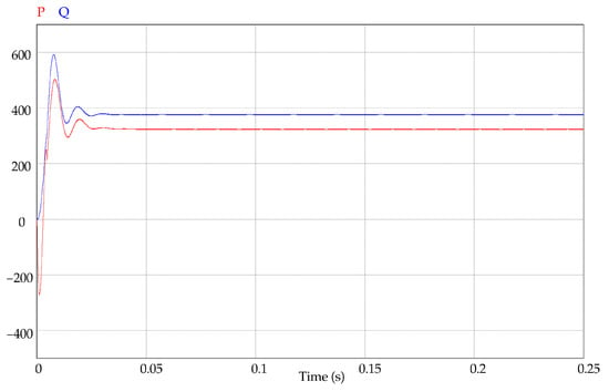
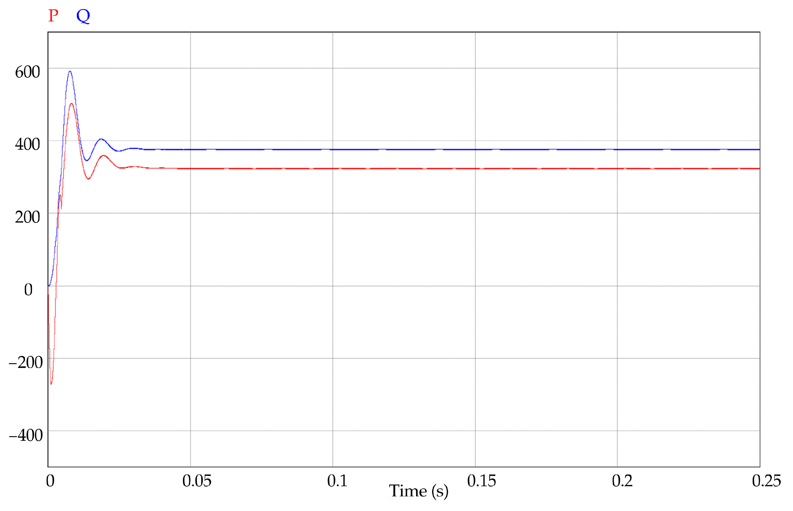
To validate the analytical operating region obtained through the steady-state solver, a representative operating point was selected and verified via time-domain simulation. This operating point corresponds to a specific constant power load demand defined by: W, var.
These values represent a feasible point located inside the analytically derived P–Q operating region and were intentionally chosen to demonstrate consistency between the algebraic steady-state solution and the dynamic response of the converter.
The selected power demand is imposed on a single-phase PWM-CSC modeled and simulated in PSIM v9. The converter is controlled using an adaptive PI–PBC strategy, which regulates the power exchange while preserving the passivity-based structure of the system [12]. For this operating condition, an output current magnitude of A is required, with a modulation phase angle of .
The PSIM implementation employs the switching representation of the PWM-CSC rather than the averaged model used to derive the equilibrium region. As a result, the simulation captures both the twice-line-frequency power pulsation inherent to single-phase conversion and the high-frequency PWM switching ripple. The formulation is thus validated in terms of period-averaged quantities, whereas the switching model is further utilized to quantify the DC-link current ripple neglected by the steady-state model.
These values are used as reference inputs for the PWM-CSC controller in the simulation environment. The resulting time-domain responses of the active and reactive power are shown in Figure 6. As observed, both power components converge to their prescribed steady-state values, closely matching the operating point obtained from the nonlinear algebraic solver.
Figure 6.
Time-domain response of active and reactive power for the selected operating point .
The transient response exhibits a short settling period with moderate oscillations, which are expected due to the interaction between the filter dynamics and the negative incremental resistance behavior of the constant power load. Nevertheless, the closed-loop system remains stable, and the steady-state values of P and Q are accurately regulated, confirming the feasibility of the selected operating point.
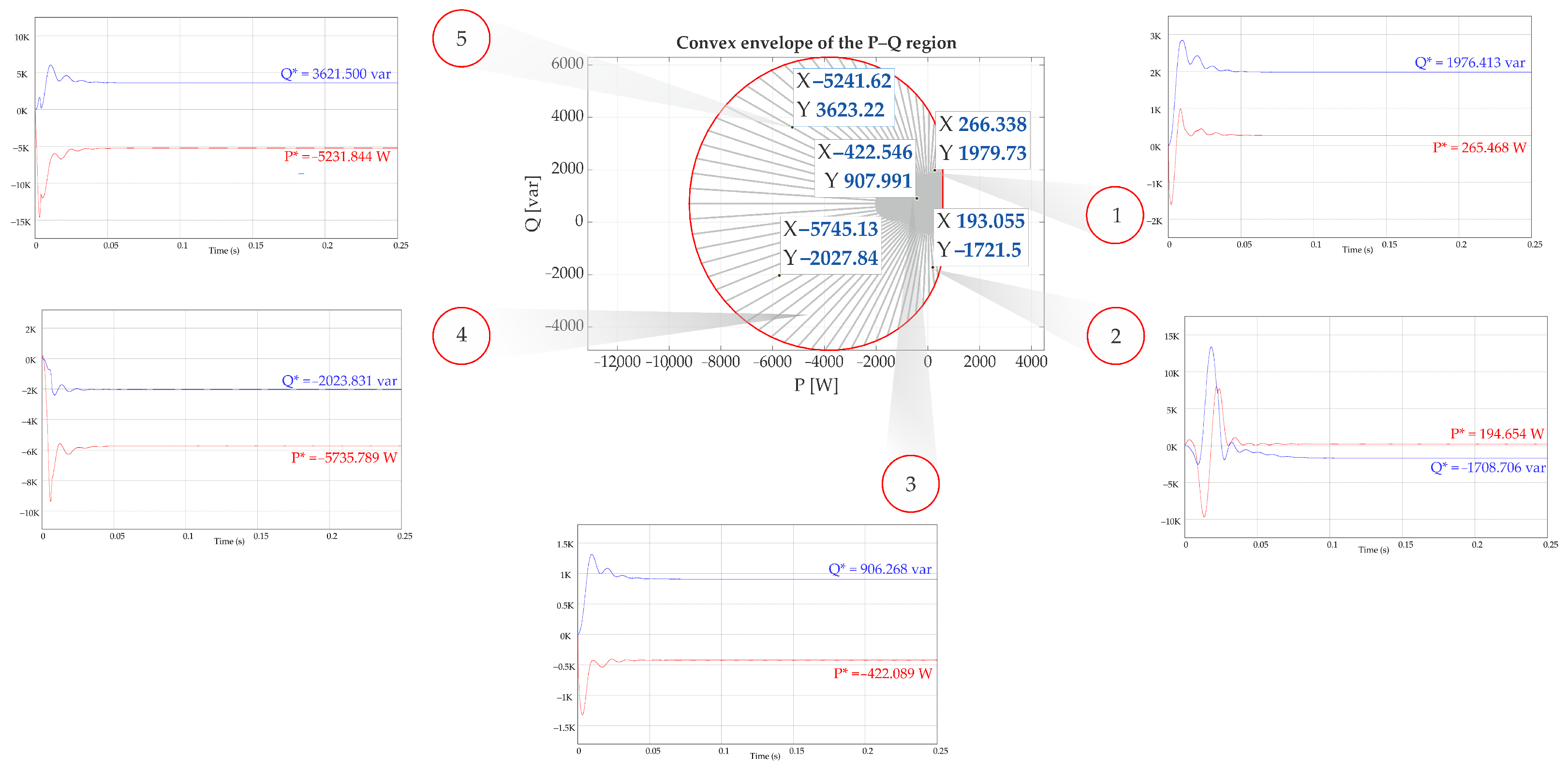
Furthermore, an additional five operating points were taken into consideration, which were distributed across a variety of areas of the feasible region. This was done so that the generality and robustness of the proposed analysis could be assessed. Each operating point corresponds to a specific CPL demand, intentionally chosen to cover different combinations of active and reactive power, including positive and negative active power flow as well as both inductive and capacitive reactive power conditions. The selected operating points, along with their analytically obtained steady-state solutions and the corresponding simulation results, are summarized in Table 2.
Table 2.
Representative CPL operating points and corresponding steady-state values obtained from analytical solution and dynamic simulation.
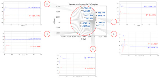
For each operating point, the steady-state solver provides the corresponding converter-side voltage magnitude , and output current magnitude , which are used as reference conditions for the dynamic simulations. Figure 7 illustrates the validation results, where the five selected operating points are highlighted. The surrounding subplots (labeled (1)–(5)) present the time-domain responses of active and reactive power for each case.
Figure 7.
Validation of representative operating points within the analytically derived P–Q operating region. (*) denotes the desired/reference active and reactive power values.
This result provides a first level of validation of the proposed operating region analysis. It demonstrates that steady-state solutions identified through the solver correspond to model-based equilibrium region when implemented in a time-domain simulation with a realistic control strategy.
6.2. Near-Boundary Operating Point: Reduced Feasibility Margin
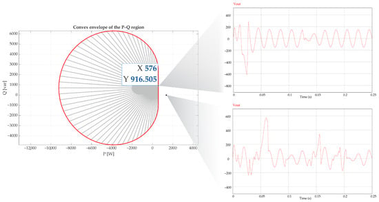
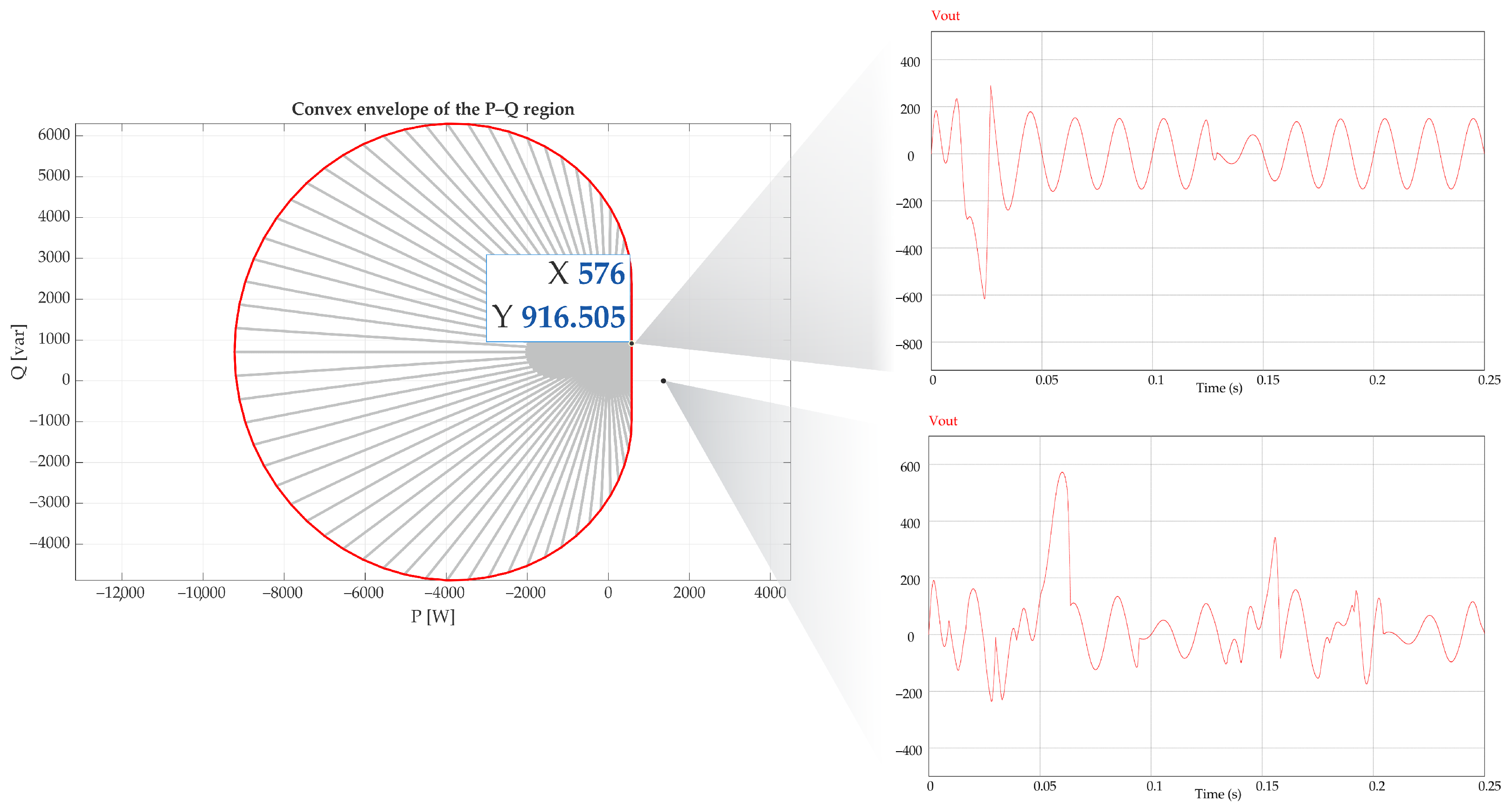
After validating a representative operating point well inside the feasible region, the analysis is extended to an operating condition located close to the boundary of the analytically derived P–Q region (Figure 8). This operating point is selected such that the steady-state solver predicts feasibility only for high modulation indices, indicating a reduced control margin.
Figure 8.
Output voltage response of the PWM-CSC for operating points located near the boundary and outside the feasible P–Q region.
The time-domain simulation results reveal that, although the converter is still capable of regulating the output voltage around its nominal value, the transient response exhibits increased oscillatory behavior, longer settling time, and reduced damping compared to operating points located well inside the feasible region.
This operating condition is also characterized by a reduced modulation margin, since the required modulation index approaches its admissible limit. Near the boundary, the modulation index approaches its upper limit, and the converter operates under constrained conditions. At the same time, the negative incremental impedance introduced by the constant power load reduces the effective damping of the system, amplifying the interaction between the converter dynamics and the load.
As a result, even though a steady-state solution exists, the system becomes more sensitive to perturbations and exhibits degraded dynamic performance. This confirms that proximity to the operating boundary not only limits feasibility but also significantly affects the transient response and modulation margin of the PWM-CSC.
6.3. Infeasible Operating Point: Loss of Voltage Regulation
The behavior of the system is further analyzed for a power demand intentionally selected outside the feasible operating region (Figure 8). In this case, the steady-state solver does not yield a physically consistent solution under the imposed constraints.
The time-domain response of the output voltage clearly shows the loss of regulation capability. Instead of converging to the nominal value, the voltage exhibits sustained oscillations or diverging behavior, depending on the operating condition. This response reflects the inability of the converter to satisfy the imposed power demand under the given modulation and voltage constraints.
From a physical standpoint, this phenomenon is explained by the absence of an equilibrium point. Since the required power cannot be delivered within the feasible operating region, the controller continuously attempts to compensate for the mismatch, driving the modulation index toward saturation. Simultaneously, the negative incremental impedance characteristic of the CPL amplifies voltage deviations, further destabilizing the system.
6.4. Computational Performance of the Feasibility Solver
Since the operating region is constructed through the repeated solution of the nonlinear algebraic system described in Section 4, the convergence characteristics of the numerical procedure are relevant for assessing its practical applicability.
Table 3 summarizes the main computational metrics obtained during the generation of the operating region. A total of 50.000 operating points were evaluated using the nonlinear solver. The results show a convergence rate of 100%, indicating that the proposed formulation remained numerically robust throughout the analyzed operating domain.
Table 3.
Computational performance metrics of the nonlinear feasibility solver used to construct the operating region.
The average solution time was 4.168 ms per operating point, with an average of 4.84 iterations and 23.35 function evaluations. Moreover, the residual norms remained below for all converged solutions, demonstrating a high level of numerical accuracy. Although some operating points required longer solution times, resulting in a maximum computation time of 1.254 s, the overall results indicate that the nonlinear algebraic formulation is well-conditioned and can be efficiently solved using standard numerical techniques.
7. Discussion
The results presented in this study offer a thorough overview of the steady-state operating capabilities of a single-phase PWM-CSC supplying a constant power load. The proposed operating region framework, which combines analytical steady-state modeling, numerical feasibility analysis, and time-domain validation, enables a unified interpretation of feasibility, control effort, and dynamic performance. From a mathematical perspective, the proposed framework characterizes the equilibrium manifold of the converter–CPL system through a nonlinear algebraic formulation and its projection onto active–reactive power operating spaces.
The first key observation is that the operating region of the P–Q plane is fundamentally shaped by the interaction between modulation constraints and the nonlinear characteristics of the CPL. Unlike conventional passive loads, the CPL imposes algebraic power constraints that can restrict the existence of steady-state solutions even when current and voltage limits are not explicitly exceeded. This is why the feasible region has an asymmetric and non-trivial shape, as demonstrated by the numerical construction and its convex hull approximation. This region cannot be inferred from linearized models alone, which highlights the importance of a nonlinear steady-state formulation.
The feasibility maps in the plane and in the P–Q plane provide complementary insights. On the one hand, the feasibility map shows that only a subset of modulation parameters leads to physically consistent solutions for a given CPL demand. Notably, the presence of a minimum modulation index for a given power demand suggests a close link between feasibility and available control authority. Conversely, the distribution of the required modulation index across the P–Q plane offers a quantitative measure of control margin.
The time-domain simulations presented in Section 6 corroborate this interpretation. For operating points located well within the feasible region, the adaptive PI–PBC controller accurately regulates active and reactive power whilst exhibiting acceptable transient behavior. As the operating point approaches the boundary of the feasible region, the closed-loop system remains stable, but there is an increase in oscillations, and the settling time becomes longer. This deterioration is consistent with the reduced modulation margin predicted by the operating region analysis, reflecting the diminished effective damping in the presence of CPL-induced negative incremental resistance.
Most importantly, simulating an operating point outside the analytically determined feasible region shows that the loss of steady-state regulation is not just a problem with the control design, but a structural limitation of the converter–load system. In this case, there is no admissible steady-state solution, so the controller is forced to operate in saturation, which leads to persistent oscillations or divergence (Figure 8). This result highlights that closed-loop control alone cannot compensate for infeasible power demands, emphasizing the practical relevance of the proposed operating region as a prerequisite for stable operation.
Although the present study focuses on steady-state feasibility, rapid CPL step changes are expected to affect the transient response more strongly near the operating boundary. In such regions, the modulation margin is reduced and the negative incremental impedance of the CPL decreases the effective damping of the converter–filter dynamics. Therefore, load-step tests would be useful for assessing controller-dependent metrics such as DC-link current oscillations, overshoot, settling time, and modulation saturation. These dynamic evaluations are beyond the scope of the present operating-region formulation and are proposed as future work focused on robustness and real-time implementation.
From a broader perspective, the proposed methodology bridges the gap between steady-state feasibility analysis and dynamic performance assessment. While feasibility does not guarantee an optimal transient response, the distance to the boundary of the operating region is a meaningful indicator of modulation margin and dynamic robustness. This insight is particularly valuable for designing and supervising the control of single-phase microgrids and stand-alone systems, where operating points can vary significantly due to changes in load or fluctuations in renewable generation.
It should be noted that the operating-region analysis presented in this work is based on the nominal steady-state model of the converter, assuming ideal sinusoidal operation and fixed system parameters. Consequently, measurement noise, sensor inaccuracies, switching ripple, parameter uncertainties, and controller bandwidth limitations are not explicitly considered. In practical implementations, these non-ideal effects may alter the transient response and reduce the effective modulation margin, particularly for operating points located near the boundary of the feasible region, where the available modulation margin is reduced and the influence of the CPL becomes more pronounced. Nevertheless, because the proposed methodology is derived from the equilibrium conditions of the converter–CPL system, the resulting operating regions remain a useful first-order approximation of the admissible operating set.
Future work will extend the proposed operating-region framework beyond the nominal feasible boundaries derived from the averaged steady-state model. In particular, the influence of practical implementation aspects, including switching losses, dead-time effects, sensor delays, measurement noise, parameter uncertainties, and component mismatch, will be investigated to assess their impact on steady-state convergence and on the robustness of the predicted operating boundaries. Since these nonidealities are expected to be more critical near the feasibility limits, future studies will incorporate switching-level models, loss mechanisms, and sensor dynamics to evaluate how the effective operating region is modified under realistic conditions. Furthermore, although the present work focuses on the existence and feasibility of equilibrium points, future research will address the local stability properties of the converter–CPL system through small-signal modeling and eigenvalue analysis, providing additional insight into the relationship between operating-region boundaries, damping characteristics, and dynamic stability margins. Finally, the proposed methodology will be extended to voltage-source converter topologies supplying constant power loads, enabling a systematic comparison of feasible operating regions, stability characteristics, harmonic performance, and control requirements between CSC- and VSC-based solutions.
8. Conclusions
The present paper sets out a systematic operating region analysis for a single-phase PWM current source converter supplying a constant power load. A comprehensive framework was developed to characterize the admissible active and reactive power operating points of the converter under CPL constraints. This was achieved by combining steady-state modeling in the synchronous reference frame, nonlinear algebraic feasibility analysis, and time-domain simulation.
The starting point for this study was the dynamic model of the PWM-CSC, from which a steady-state formulation was derived under the assumption of sinusoidal operation. By setting time derivatives to zero, the converter–load system was reduced to a set of nonlinear algebraic equations linking voltages, currents, modulation index, and phase angle. This formulation enabled the explicit incorporation of constant power load constraints and revealed the intrinsic limitations imposed by modulation and DC-side parameters.
The feasible operating region was constructed numerically through parametric sweeps in the modulation variables and in the P–Q plane. The resulting operating region manifests a non-trivial geometry, significantly influenced by the nonlinear characteristics of the CPL and the current source properties of the converter. The utilization of convex hull approximations furnished a pragmatic depiction of the operational limits, while color-coded maps of the modulation index offered significant insight into the distribution of control effort across the feasible region.
A significant contribution of this work is the interpretation of feasibility not only as the existence of a steady-state solution but also as an indicator of control margin. Operating points that are located well within the feasible region require lower modulation indices and exhibit more favorable dynamic behavior. In contrast, points that are located near the boundary demand higher modulation effort and show reduced damping. Time-domain simulations utilizing an adaptive PI–PBC controller provided validation for this interpretation, demonstrating consistent correspondence between solver-predicted feasibility and dynamic performance. Conversely, operating points that lie outside the feasible region resulted in the loss of steady-state regulation, thereby confirming the notion that unfeasible demands cannot be compensated for by control action alone.
The results obtained demonstrate the significance of operating region analysis as a design and supervisory tool for single-phase current source converters supplying constant power loads. The proposed framework establishes a clear correlation between steady-state feasibility, modulation constraints, and dynamic behavior. It is readily extensible to support power management, operating point selection, and feasibility-aware control design.
Subsequent endeavors will concentrate on expanding the proposed analysis to encompass parameter uncertainties, small-signal stability evaluation around steady-state operating points, and experimental validation on hardware prototypes. Furthermore, the extension of the methodology to multi-converter systems and three-phase configurations represents a promising direction for further research.
Author Contributions
Conceptualization and methodology: A.M.N.-V., C.R.B. and N.L.D.-A.; algorithm development and software: A.M.N.-V. and C.R.B.; validation and analysis: A.M.N.-V., W.G.-G.; writing (original draft preparation): A.M.N.-V., C.R.B. and O.D.M.; writing (review and editing): all authors. All authors have read and agreed to the published version of the manuscript.
Funding
This research was funded by the Agencia Nacional de Investigación y Desarrollo (ANID), Chile, through FONDECYT Regular Project No. 1250838. The authors also acknowledge the support provided by Thematic Network 723RT0150, Red para la integración a gran escala de energías renovables en sistemas eléctricos (RIBIERSE-CYTED), funded through the 2022 call for thematic networks of the CYTED (Ibero-American Program of Science and Technology for Development).
Data Availability Statement
The original contributions presented in this study are included in the article. Further inquiries can be directed to the corresponding author.
Acknowledgments
The authors acknowledge the use of AI-based tools, specifically DeepSeek V3.0, to support the refinement of the manuscript’s language, structure, and overall clarity. These tools were used exclusively to improve the presentation and readability of the original ideas, formulations, and numerical simulations provided by the authors. Importantly, the AI tools did not contribute to the development of the scientific content, the formulation of the research, or the validity of the results, for which the authors assume full responsibility.
Conflicts of Interest
The authors declare no conflicts of interest.
Abbreviations
The following abbreviations are used in this manuscript:
| CPL | Constant Power Load |
| DC | Direct Current |
| AC | Alternating Current |
| VSC | Voltage Source Converter |
| CSC | Current Source Converters |
| P | Active power |
| Q | Reactive power |
| PWM | Pulse-Width Modulation |
| PLL | Phase-Locked Loop |
References
- Fotopoulou, M.; Tsekouras, G.J.; Rakopoulos, D.C.; Kanellos, F.D.; Kontargyri, V.T. Investment Planning Optimization for Energy Communities with Photovoltaic and Storage. IEEE Access 2026, 14, 98275–98294. [Google Scholar] [CrossRef] [Scilit]
- Ganthia, B.P.; Praveen, B. Microgrid Sources and Power Electronic Interfaces: A Comprehensive Review on Source Characteristics, Converter Design, Protection, Power Quality, and Energy Storage Integration. Int. J. Power Electron. Control. Convert. 2025, 11, 30–61. Available online: https://journalspub.com/publication/ijpecc/article=22849/ (accessed on 3 July 2026).
- Hassan, M.A.; Worku, M.Y.; Eladl, A.A.; Elkadeem, M.R.; Hossain, M.I.; Abido, M.A. Instability Mitigation of Constant Power Load in Microgrid. Arab. J. Sci. Eng. 2024, 49, 7341–7358. [Google Scholar] [CrossRef] [Scilit]
- Ponce, E.A.; Leeb, S.B. Impedance Modeling for Line-Frequency Rectified Constant-Power Loads. IEEE Access 2025, 13, 92213–92226. [Google Scholar] [CrossRef] [Scilit]
- Zhang, H.; Jiang, C.; Xu, X. Observer-Assisted Stability-Margin-Driven Prescribed-Time Distributed Control for Islanded DC Microgrids: Enhancing System Stability Under Large-Signal CPL Disturbances. Mathematics 2026, 14, 1682. [Google Scholar] [CrossRef] [Scilit]
- Maurya, R.; Singh, A.K. Actor-Critic RL Approach to Stabilize Voltage in DC Microgrids for Linear, CPL, and PPL Load Profiles. In Proceedings of the 2025 IEEE 14th International Conference on Communication Systems and Network Technologies, CSNT 2025, Bhopal, India, 7–9 March 2025; pp. 1268–1276. [Google Scholar] [CrossRef] [Scilit]
- Jiang, X.; Zhou, Y.; Ming, W.; Wu, J. Feasible operation region of an electricity distribution network. Appl. Energy 2023, 331, 120419. [Google Scholar] [CrossRef] [Scilit]
- Shivam; Kumar, M. Circulating Current Control of LVDC Microgrid Based on Optimal Offset Voltage Decentralized Control Scheme with CPLs. J. Inst. Eng. Ser. B 2022, 104, 91–103. [Google Scholar] [CrossRef] [Scilit]
- Güngör, M.; Asker, M.E.; Güngör, M.; Asker, M.E. Learning-Based Approaches for Voltage Regulation and Control in DC Microgrids with CPL. Sustainability 2023, 15, 5501. [Google Scholar] [CrossRef] [Scilit]
- Hassan, M.A.; Su, C.L.; Pou, J.; Sulligoi, G.; Almakhles, D.; Bosich, D.; Guerrero, J.M. DC Shipboard Microgrids with Constant Power Loads: A Review of Advanced Nonlinear Control Strategies and Stabilization Techniques. IEEE Trans. Smart Grid 2022, 13, 3422–3438. [Google Scholar] [CrossRef] [Scilit]
- Radwan, A.A.A.; Elshenawy, M.A.; Mohamed, Y.A.R.I.; El-Saadany, E.F. Grid-Forming Current-Source Converter for a Full-Scale Wind Energy Conversion System. IEEE Open J. Power Electron. 2025, 6, 327–343. [Google Scholar] [CrossRef] [Scilit]
- Nivia-Vargas, A.M.; Montoya, O.D.; Díaz, N.L. Adaptive PI-PBC Performance via Proportional Gain Scaling in Single-Phase PWM-CSC under Linear Current Demand. In Proceedings of the 2025 22nd International Conference on Electrical Engineering, Computing Science and Automatic Control (CCE), Mexico City, Mexico, 22–24 October 2025; pp. 1–5. [Google Scholar] [CrossRef] [Scilit]
- Cheah-Mane, M.; Egea-Alvarez, A.; Prieto-Araujo, E.; Mehrjerdi, H.; Gomis-Bellmunt, O.; Xu, L. Modeling and analysis approaches for small-signal stability assessment of power-electronic-dominated systems. Wiley Interdiscip. Rev. Energy Environ. 2023, 12, e453. [Google Scholar] [CrossRef] [Scilit]
- Ansari, S.; Zhang, J.; Singh, R.E. A review of stabilization methods for DCMG with CPL, the role of bandwidth limits and droop control. Prot. Control Mod. Power Syst. 2022, 7, 2. [Google Scholar] [CrossRef] [Scilit]
- Baier, C.R.; Melin, P.E.; Torres, M.A.; Ramirez, R.O.; Muñoz, C.; Quinteros, A.; Baier, C.R.; Melin, P.E.; Torres, M.A.; Ramirez, R.O.; et al. Developing and Evaluating the Operating Region of a Grid-Connected Current Source Inverter from Its Mathematical Model. Mathematics 2024, 12, 1775. [Google Scholar] [CrossRef] [Scilit]
- Xia, Z.; Su, M.; Liu, Z.; Liu, R.; Liu, Y. Existence Conditions and Stability for the Power-Flow of DC Micro-Grids with CPLs. IEEE Trans. Smart Grid 2022, 13, 4284–4299. [Google Scholar] [CrossRef] [Scilit]
- AL-Nussairi, M.K.; Bayindir, R.; Padmanaban, S.; Mihet-Popa, L.; Siano, P. Constant Power Loads (CPL) with Microgrids: Problem Definition, Stability Analysis and Compensation Techniques. Energies 2017, 10, 1656. [Google Scholar] [CrossRef] [Scilit]
- Nivia-Vargas, A.M.; Giraldo, O.D.M.; Gil-González, W.J. Comparative Analysis of Control Strategies for Single-Phase PWM-CSCs Feeding Linear Loads: IDA-PBC, Nonlinear PI, and PI-PBC Approaches. Stat. Optim. Inf. Comput. 2025, 14, 1337–1355. [Google Scholar] [CrossRef] [Scilit]
- Ikaouassen, H.; Raddaoui, A.; Rezkallah, M. Performance and Stability Analysis of Enhanced Lyapunov Function and Predictive Voltage Control with Active Damping for Single-Phase PV/Grid Electric Power System. Iran. J. Sci. Technol. Trans. Electr. Eng. 2024, 48, 731–746. [Google Scholar] [CrossRef] [Scilit]
- Trabelsi, M.; Makhamreh, H.; Alquennah, A.N.; Vahedi, H. Lyapunov-Based Model Predictive Control for Stable Operation of a 9-Level Crossover Switches Cell Inverter in Grid Connection Mode. In Proceedings of the IECON Proceedings (Industrial Electronics Conference), Singapore, 16–19 October 2023. [Google Scholar] [CrossRef] [Scilit]
- Gupta, R.; Singh, N. Fuzzy logic feed-forward impedance shaping of DAB converter in DC microgrid with CPL load. J. Power Electron. 2023, 23, 1576–1584. [Google Scholar] [CrossRef] [Scilit]
- Li, D.; Sun, Q.; Wang, R.; Sui, Z.; Wang, P. Dynamic Current Control Strategy of Grid-Connected Voltage Source Converters Feeding Constant Power Loads for Transient Stability Enhancement. IEEE Trans. Energy Convers. 2026, 41, 2105–2118. [Google Scholar] [CrossRef] [Scilit]
- Fan, E.; Jiang, W.; Xiong, P.; Bai, J.; Ma, R.; Zhou, Y. A Combined Stabilization Method for the VSC Feeding the DC Microgrid. In Proceedings of the CPSS and ISESC 2024—2024 CPSS and IEEE International Symposium on Energy Storage and Conversion, Xi’an, China, 8–11 November 2024; pp. 98–102. [Google Scholar] [CrossRef] [Scilit]
- Mohamad, A.M.; Mohamed, H.R.A.; Mohamed, Y.A.R.I. Impedance-Based Stability Analysis of a Low-Inertia AC Grid Connected to a DC Grid by a VSC With Virtual Inertia Controllers. IEEE Open J. Power Electron. 2025, 6, 485–503. [Google Scholar] [CrossRef] [Scilit]
- Nithara, P.V.; Anand, R.; Ramprabhakar, J.; Meena, V.P.; Khan, B. A passivity based nonlinear controller for hybrid DC microgrid with constant power loads. Sci. Rep. 2025, 15, 16904. [Google Scholar] [CrossRef] [Scilit] [PubMed]
- Rahman, M.M.; Mohamed, Y.A.R.I. Interaction Dynamics and Active Suppression of Instability in Parallel Photovoltaic Voltage-and Current-Source Converters Connected to a Weak Grid. IEEE Open J. Power Electron. 2023, 4, 395–414. [Google Scholar] [CrossRef] [Scilit]
- Dash, D.K.; Sadhu, P.K.; Dash, D.K.; Sadhu, P.K. A Review on the Use of Active Power Filter for Grid-Connected Renewable Energy Conversion Systems. Processes 2023, 11, 1467. [Google Scholar] [CrossRef] [Scilit]
- Yuan, C.; Lin, X. Graph-temporal convolutional network for steam heating network simulation considering dynamic characteristics. Energy 2025, 333, 137567. [Google Scholar] [CrossRef] [Scilit]
- Nivia-Vargas, A.M.; Montoya, O.D.; Gil-González, W. Nonlinear Control Design for a Single-Phase PWM-CSC with an Adaptive Load Estimation. In Proceedings of the 2024 IEEE Colombian Conference on Applications of Computational Intelligence (ColCACI), Pamplona, Colombia, 17–19 July 2024; pp. 1–6. [Google Scholar] [CrossRef] [Scilit]
- Daryaei, M.; Khajehoddin, S.A.; Mashreghi, J.; Afridi, K.K. A New Approach to Steady-State Modeling, Analysis, and Design of Power Converters. IEEE Trans. Power Electron. 2021, 36, 12746–12768. [Google Scholar] [CrossRef] [Scilit]
- Al-Sabaeei, M.N.H.; Nazib, A.A.B. Comparative Analysis of Control Strategies for 3-Phase Grid-Connected Inverters: Stationary vs. Synchronous Frame Approaches with LCL Filtering. J. Phys. Conf. Ser. 2025, 2998, 012005. [Google Scholar] [CrossRef] [Scilit]
- Baier, C.R.; Torres, M.A.; Munoz, J.; Guzman, J.I.; Melin, P.E.; Rothen, J.; Rivera, M. D-q-DC reference frame control strategy for single-phase current source cascaded inverters. In Proceedings of the IECON Proceedings (Industrial Electronics Conference), Dallas, TX, USA, 29 October–1 November 2014; pp. 4615–4621. [Google Scholar] [CrossRef] [Scilit]
- Agrawal, R.; McGrath, B.P.; Teixeira, C.A.; Wilkinson, R.H. A Small Signal Rotating Frame Model of a Self-synchronizing Single-phase Grid-tied Inverter. In Proceedings of the ICPE 2023—ECCE Asia—11th International Conference on Power Electronics—ECCE Asia: Green World with Power Electronics, Jeju, Republic of Korea, 22–25 May 2023; pp. 778–785. [Google Scholar] [CrossRef] [Scilit]
- Rasheduzzaman, M.; Mueller, J.A.; Kimball, J.W. An accurate small-signal model of inverter-dominated islanded microgrids using (dq) reference frame. IEEE J. Emerg. Sel. Top. Power Electron. 2014, 2, 1070–1080. [Google Scholar] [CrossRef] [Scilit]
- Yepes, A.G.; Vidal, A.; Lopez, O.; Doval-Gandoy, J. Evaluation of techniques for cross-coupling decoupling between orthogonal axes in double synchronous reference frame current control. IEEE Trans. Ind. Electron. 2014, 61, 3527–3531. [Google Scholar] [CrossRef] [Scilit]
- Kumar, A.; Mohapatra, A.; Singh, S.N.; Panda, R.K. Space Vector Rotation-Based Controlled Decaying Current Injection for Islanding Detection of Inverter-Interfaced DG. IEEE Trans. Smart Grid 2022, 13, 4638–4650. [Google Scholar] [CrossRef] [Scilit]
- Fang, J.; Si, W.; Xing, L.; Goetz, S.M. Analysis and Improvement of Transient Voltage Stability for Grid-Forming Converters. IEEE Trans. Ind. Electron. 2024, 71, 7230–7240. [Google Scholar] [CrossRef] [Scilit]
- Yang, H.; Yuan, X.; He, W. Active/Reactive Power Separation Mechanisms for Different Signal-Modulated Power Devices Based on Time-Varying Amplitude/Frequency Rotating Vectors in Dynamic Processes. Processes 2025, 13, 1907. [Google Scholar] [CrossRef] [Scilit]

Disclaimer/Publisher’s Note: The statements, opinions and data contained in all publications are solely those of the individual author(s) and contributor(s) and not of MDPI and/or the editor(s). MDPI and/or the editor(s) disclaim responsibility for any injury to people or property resulting from any ideas, methods, instructions or products referred to in the content. |
© 2026 by the authors. Licensee MDPI, Basel, Switzerland. This article is an open access article distributed under the terms and conditions of the Creative Commons Attribution (CC BY) license.