


Highlights
- System-level jet and fuel cell hybrid engine models considering mass and volume are established.
- The maximum overall efficiency of the proposed hybrid engine is 63% without mass and volume constraints.
- Both weight and volume exhibit exponential increasing trends with the overall efficiency when it exceeds 50%.
- The weight and volume of the hybrid engine have a linear relationship with the overall efficiency when the efficiency is lower than 50%.
- The thermal efficiency for the novel hybrid engine is increased by 21% compared with that of CFM56 3C1.
- The propulsion efficiency for the novel hybrid engine is increased by 42% compared with that of CFM56 3C1.
Abstract
Mass and volume penalties associated with fuel cell integration have hindered the manufacturing and integration of hybrid power systems into civil aircraft. To address this issue, a novel scheme, a turbofan engine integrated with solid oxide fuel cells, is proposed in this paper, which has the advantage of high thermal efficiency and propulsion efficiency, where the electricity produced by the solid oxide fuel cell (SOFC) is used to drive the ducted fan. Then, a multidimensional model that accounts for mass, volume, and thermodynamic performance is established. The equivalence ratio and split ratio have a significantly stronger influence on the volume and mass ratios than the current density. These two parameters directly determine the power ratio between the fuel cell and the gas turbine. An increase in the power ratio leads to a simultaneous rise in both the volume and mass ratios; however, the overall efficiency cannot be continuously improved, with its maximum value being approximately 63% without mass and volume constraints. During the multi-objective optimization process, the weight and volume of the hybrid engine have a linear relationship with the overall efficiency when the efficiency is lower than 50%. However, both mass and volume exhibit exponential increasing trends as the overall efficiency is over 50%. This is caused by the nonlinear change in the fuel cell reaction area; as polarization loss decreases, the thermal efficiency of the hybrid system improves. The maximum overall efficiency is taken as the optimization objective, with the constraints that the mass fraction of the fuel cell does not exceed 0.4 of the total engine mass and that the volume fraction of the fuel cell stack is less than 0.2 of the gas turbine engine volume. Compared with the CFM56 3C1, the thermal efficiency for the novel hybrid engine is increased by 21%, and its propulsion efficiency is increased by 42%.
1. Introduction
1.1. Low-Carbon Propulsion in Civil Aviation
The rapid growth of air transportation has made civil aviation a significant anthropogenic contributor to global CO2 emissions, accounting for 2.5% of the global CO2 emissions from human activities [1]. To address the challenge, the international aviation industry has set a net-zero carbon emissions goal by 2050. The European Union has also passed legislative initiatives to gradually increase the blending ratio of SAF (Sustainable Aviation Fuel) in flights. However, the global production of SAF accounted for only 0.2% of total aviation fuel consumption in 2023 [2]. Despite capacity expansion, which may meet the EU’s 6% requirement by 2030, a global supply gap is still expected.
Battery energy storage, liquid hydrogen propulsion, and Power-to-Liquid (PtL) synthetic fuels are the three most promising technological pathways for carbon-neutral aviation [3]. However, aviation is extremely sensitive to the weight and volume of the propulsion systems and energy carriers. The energy density of current battery-powered propulsion systems is typically less than 500 Wh/kg, which is insufficient to meet the needs of medium- and long-range commercial airliners. In contrast, the energy density of hydrogen reaches 120 MJ/kg, about three times that of conventional jet fuel [4]. Adler E J et al. [3] found that liquid hydrogen aviation systems reduced primary energy demand by 15–30% compared to PtL aircraft, highlighting the strategic value of green hydrogen for improving life-cycle energy efficiency. Hydrogen fuel cells have high efficiency, as they directly convert hydrogen energy into high-quality electrical energy through electrochemical reactions [5].
Developing low-carbon propulsion systems is essential for reducing aviation’s climate impact. SAF is only a transitional solution, while green hydrogen–fuel cell systems offer a long-term zero-emission pathway. However, challenges remain, including hydrogen’s low volumetric energy density and limited power density of aviation fuel cell systems.
1.2. Solid Oxide Fuel Cell–Gas Turbine Hybrid Engine
SOFC-GT combines the high efficiency of solid oxide fuel cells (SOFCs) with the high power density of gas turbines (GTs), enabling near-zero-emission. Seyam et al. [6] indicated that the efficiency of SOFC-GT systems was expected to exceed 59%. The SOFC-GT system introduces additional weight penalties, but efficiency gains on long-haul flights offset this weight penalty, showing its potential for application in large aircraft.
However, there are still technical challenges in the aviation application of SOFC-GT. Gunaltili et al. [7] reported SOFC-GT efficiency of 60–80%, highly dependent on the deep integration of fuel cells and turbines.
- (1)
- Hybrid engine architecture
Scholars have proposed various SOFC-GT architectures, notably FLyCLEEN for 200-seat aircraft. Leal and Ribeiro [8] described a zero-emission SOFC-GT architecture, demonstrating that the integration of SOFCs and gas turbines could significantly improve the system energy and exergy efficiencies of the system. For mid-range commercial aircraft, Daggett et al. [9] designed a liquid hydrogen SOFC-GT hybrid architecture, whose fuel mass consumption could be reduced by 40–50% compared to conventional jet fuel propulsion.
Ji et al. [10] proposed a dual-mode engine that integrated fuel cells, a gas turbine, and an electric motor for wide-body aircraft. This engine improved efficiency as well as the working environment for motors and electronic devices by utilizing the cryogenic energy of liquid hydrogen. Ji et al. [11] also used multidisciplinary coupled design to balance propulsion system weight and thermal load. In addition, Chen et al. [12] proposed multi-objective optimization for SOFC-GT power matching. This SOFC-GT configuration had a cruise efficiency of 65.1% for long-endurance unmanned aerial vehicles.
- (2)
- Steady-State Thermal Performance
Once the system architecture has been determined, steady-state and thermodynamic analysis assess feasibility and optimize system parameters. SOFC-GT coupling involves heat, mass transfer, and electrochemical reactions. Studies often employed thermodynamics laws to quantitatively evaluate performance across flight conditions. Pratt et al. [13] performed ideal-cycle analysis showing that matching the pressure ratio and SOFC temperature improves efficiency over the Brayton cycle.
Then, Xu et al. [14] showed that the dual-shaft hybrid system improved efficiency, while it required a strict trade-off optimization with the fuel cell’s thermal management to prevent thermal stress failure and performance degradation. Hybrid steady-state performance depends on both cycle parameters and fuel. SOFC fuel flexibility enables thermodynamic comparison of different fuels. Liu et al. [15] employed exergy analysis to compare SOFC-GT systems fueled by liquid hydrogen (LH2), liquefied natural gas (LNG), and aviation kerosene (Jet-A) and found that the thermal efficiency of SOFC-GT achieved nearly 63%, higher than the 54% of jet fuel.
Ammonia, due to its high volumetric energy density and ease of liquefaction for storage, is also an important zero-carbon aviation fuel. Wagner et al. [16] reported that an ammonia-fueled SOFC-GT system achieved nearly 60% cruise thermal efficiency in Boeing 737–800 applications. Chemical hydrogen storage combined with SOFCs offers a safer, and more compact solution for hydrogen storage and transportation. Chen et al. [17] proposed a sodium borohydride/aluminum hydrolysis hydrogen production system coupled with an SOFC-GT system, which achieved an exergy efficiency of 49.3%, with major losses from hydrolysis and polarization.
The SOFC-GT hybrid system also demonstrates excellent performance in supersonic and hypersonic aircraft. Focusing on a Mach 3.5 supersonic transport aircraft, Xu et al. [18] showed that SOFC-driven compressors and cryogenic precooling improved thrust and efficiency. In applications at higher Mach numbers, Kuai et al. [19] found that steam reforming had stronger cooling capabilities and higher SOFC power compared to dry reforming. SOFC-GT hybrid systems, as indicated by steady-state calculations, can significantly improve efficiency, reduce fuel consumption, and enable low- or zero-carbon emissions.
Some studies have also been conducted to address dynamic operating conditions, such as takeoff, climb, and cruise, prior to commercial application. These efforts were motivated by the mismatch in response characteristics between SOFCs and gas turbines: the gas turbine provides rapid thrust response, whereas the SOFC is highly sensitive to thermal stress. To accurately capture the transient characteristics under varying operating conditions, scholars have developed various integrated dynamic models [20,21], providing a theoretical foundation for the successful application of SOFC-GT hybrid systems in aviation.
- (3)
- Solid Oxide Fuel Cell Lightweight Design
Although the high efficiency of SOFC-GT systems has been confirmed, aviation applications require high power density. Improving power density through component-level optimization, advanced manufacturing, and system integration remains a key challenge.
Pesterfield et al. [22] developed an integrated combustion chamber, reducing the amount of heat exchange equipment as well as system volume. High temperature-pressure stresses affect the SOFC seal and packaging weight. Schafer et al. [23] pointed out that fuel leakage can lead to performance degradation and safety hazards.
Increasing the SOFC stack power density can effectively offset its weight disadvantage, and pressurization is an important approach. Pratt et al. [24] experimentally demonstrated that pressurization from 1 to 4 bar increased peak power density by approximately 10%. In system-level experiments, Kojima et al. [25] developed a 1.5 kW SOFC and 10 kW GT hybrid platform, showing that the fuel supply and pressure control must be highly integrated to preserve efficiency gains. Some scholars have studied research progress in SOFCs in the fields of electrochemical characterization, durability enhancement, and key material optimization [26,27,28,29,30]. These studies cover advanced impedance spectroscopy analysis methods, anode structural engineering [30], cathode poisoning tolerance [29], and high-temperature stability design of interconnects [28]. These studies provide important theoretical and technical support for the application of SOFC-GT low-carbon energy systems. To address mass-related challenges, academia and industry use advanced manufacturing. Airbus emphasizes that high specific power density is crucial for aviation fuel cell applications. Using COMSOL Multiphysics simulations, Geisler et al. [31] demonstrated the importance of developing lightweight components, pressure-resistant lightweight casings, and stack configurations with low cooling flow rates. Ahilan et al. [32] applied 3D printing to enable lightweight aerospace-grade SOFCs beyond traditional manufacturing limits.
However, the use of lightweight and high-power-density technologies may lead to SOFC performance degradation. Vilela et al. [33] indicated that lightweight, high-power applications required stricter lifetime management to control the microscopic degradation mechanisms.
As summarized in Table 1, increasing pressure and cycle optimization can improve the power density of SOFC-GT systems; however, their application in aviation is constrained by the weight and volume of the stacks and other components. Integrated chambers, improved seals, and 3D-printed ultrathin stacks aim to overcome SOFC-GT component-level bottlenecks. However, balancing power density, lightweight design, and thermal efficiency remains the most critical engineering challenge.
Table 1.
Measures to increase weight or volume power density.
1.3. Original Contributions of This Work
The original contributions of this work can be summarized as follows:
- (1)
- A novel integrated modeling framework for a turbofan solid oxide fuel cell hybrid engine is developed, in which the power produced by fuel cells is used to drive the ducted fans. The thermal efficiency and propulsion efficiency are significantly improved simultaneously.
- (2)
- A unified mass–volume constrained design methodology, aimed at the fuel cell hybrid engine, is proposed. This methodology systematically incorporates both gravimetric and volumetric metrics into the system-level optimization, addressing a key limitation of existing studies that predominantly focus on single-objective thermodynamic performance.
- (3)
- A comprehensive performance optimization framework is constructed based on multidisciplinary design optimization, through which the trade-offs among efficiency, specific power, and system compactness are quantitatively evaluated.
- (4)
- New insights into the coupling mechanism and performance limits of turbofan solid oxide fuel cell hybrid engines are provided, offering theoretical guidance for the design of next-generation propulsion systems for regional and narrow-body aircraft.
1.4. Research Framework
The structure of this paper is as follows: Firstly, the overall system architecture and working principle are described. The mathematical models for the hybrid engines are presented, which include the SOFC models and the component models related to the jet engines, such as fans, turbines, etc. The models are validated against experimental data published in the literature. Subsequently, the performance analysis is conducted, which is divided into three subsections: (1) The effects of the key parameters on the performance and size of the hybrid engine are described. (2) We conduct multidisciplinary optimization study to quantify the relationship between the volume or mass of the engine and the overall efficiency of specific fuel consumption. Simultaneously, the variation trends of the other parameters are monitored. (3) According to the optimization results, the comparisons between the proposed engine and the kerosene turbofan in terms of the performance and size are completed.
2. System Architecture of the Turbine Fuel Cell Hybrid Power System
2.1. Turbofan Engine Integrated with Solid Oxide Fuel Cell Architectures
The schematic diagrams of the aerodynamic structure and the thermodynamic cycle for the turbine fuel cell hybrid power system are shown in Figure 1a and Figure 1b, respectively. Fresh air enters the intake and is compressed by the fan. Then, most of the compressed air flows into the bypass duct, where it expands and generates thrust. The remaining air enters the core flow stream, participating in the electrochemical cycle and the Brayton cycle. The core air enters the compressor, where it is compressed, heated, and pressurized. After heat exchange with the turbine exhaust gases, the temperature of the compressed air reaches the required inlet temperature for the SOFC, and then the compressed air flows into its cathode. Similarly, the fuel is preheated by exchanging heat with the exhaust gases from the combustion chamber outlet until its pressure and temperature reach the required operating conditions of the SOFC. Electricity is generated through the electrochemical reaction of fuel and air in the fuel cell. Then, the exhaust gas from the fuel cell and fresh fuel are thoroughly mixed in the mixing chamber and subsequently fed into the combustion chamber. The exhaust gas from the combustion chamber, after heat exchanging with fresh fuel, is sequentially delivered to the high-pressure turbine and the low-pressure turbine. The shaft power produced by the high-pressure turbine is entirely used to drive the compressor, while the low-pressure turbine drives the fan. After heat exchanging with air, the turbine exhaust gas flows to the core nozzle, where it expands and generates thrust. Meanwhile, the electricity generated by the fuel cell through electrochemical reactions is supplied to the electric motor, which is used to drive the ducted fan; the fuel cell no longer contributes to driving the compressor, thereby forming a multi-power-source parallel propulsion coupling configuration. The thrust of the hybrid power system is generated by three components: the core nozzle, bypass nozzle, and duct fan nozzle.
Figure 1.
Configuration and thermodynamic characteristics of the turbine fuel cell hybrid propulsion system.
Compared to traditional high-bypass turbofan engines, the turbine fuel cell hybrid engine significantly increases the bypass ratio of the jet engine by incorporating a ducted fan: (1) On one hand, fuel cell has high efficiency; by applying the principle of cascaded fuel utilization, the chemical energy utilization of the hybrid engine can be remarkably improved, thereby increasing its thermal efficiency. (2) On the other hand, the ducted fan provides high propulsion efficiency, thereby significantly improving the turbine propulsion efficiency. Under the combined effect of improved thermal efficiency and propulsion efficiency, the specific fuel consumption of the proposed novel turbine fuel cell hybrid system can be significantly reduced compared to that of a conventional turbine engine.
2.2. Architecture Comparisons of Turbine Fuel Cell Hybrid Power Systems
To minimize the mass penalty associated with volume and weight, the architectures of the turbofan engine integrated with solid oxide fuel cells are proposed in Figure 1, which are different from the currently proposed configurations [9,13,16,20,34,35] shown in Table 2. Not all thrust is produced by electrically driven ducted fans. The mass penalty from the motors and generators is limited to some degree. The degree of reduction depends on the proportion of propulsion work distributed. On the other hand, it does not represent a fully original approach. Hydrogen is selected as the fuel, eliminating the need for complex fuel processing systems.
Table 2.
Comparison of system architectures based on the combination of solid oxide fuel cells and a gas turbine for aircraft propulsion and power.
3. Mathematical Models
3.1. SOFC Model
In the turbine fuel cell hybrid system proposed in the present work, the fuel cell used is a high-temperature SOFC, and its structural schematic is shown in Figure 2a. This fuel cell mainly consists of six parts: the cathode layer, anode layer, electrolyte layer, anode fuel channel, cathode air channel, and connector. The cathode layer, anode layer, and electrolyte layer are collectively referred to as the PEN structure, which serves as the main region for electrochemical reactions. In an SOFC, the electrochemical reaction between hydrogen and oxygen primarily takes place within the PEN structure.
Figure 2.
Structural schematics of the solid oxide fuel cell unit and stack. (a) Solid oxide fuel cell unit [36]; (b) Fuel cell stack [20].
Given that the operating conditions of each single SOFC can be kept consistent, multiple cells can be stacked to form a fuel cell stack to enhance output power, as illustrated in Figure 2b [20]. In this stack, the dedicated gas manifold is used to centrally distribute and recover the working fluid. Based on the analysis of the stack’s structural characteristics and operating principles described above, the thermodynamic and electrochemical models for the SOFC are developed in this section. The thermodynamic model of SOFCs primarily consists of chemical reaction models and models for the conservation of mass, energy, and momentum.
To simplify the model calculation process, reduce computational complexity, and ensure the accuracy of the description of the main mechanisms, the following simplifying assumptions are employed: (1) The airflow throughout the entire fuel cell system is considered zero-dimensional, flowing along the axial direction, and the aerodynamic parameters at each cross-section are assumed to be uniformly distributed. (2) All gases are considered as ideal gases. (3) The oxygen content in air is 21%, and the nitrogen content is 79%. (4) The reactants and products within the fuel cell are assumed to be uniformly mixed. (5) The outlet temperature of the fuel cell is taken as the operating temperature of the fuel cell.
3.1.1. Chemical Reaction Model
Hydrogen is the only fuel reactant in this model; therefore, the main electrochemical reactions in the fuel cell are the oxidation of hydrogen (at the anode) and the reduction of oxygen (at the cathode). The SOFC electrolyte is a fully stable sintered solid-solution material. When high-valence metal ions are replaced by low-valence metal ions, a large number of oxygen ion vacancies are generated within the electrolyte to maintain charge balance. These vacancies serve as transport pathways for oxygen ions and enable oxygen ions to migrate from the cathode to the anode. Then, at the anode–electrolyte interface, the oxygen ions ultimately react with hydrogen ions to form water vapor. The specific electrochemical reactions are as follows:
3.1.2. Mass–Energy–Momentum Conservation Model
The conservation equations of mass, energy, and momentum are used to quantitatively describe the SOFC chemical reactions and transport processes in key regions such as the electrodes, electrolyte, and gas channels: (1) The mass conservation equation characterizes the overall conservation of mass of reactants and products during the electrochemical reaction. (2) The energy conservation equation describes the conversion and conservation of energy within the system. The input chemical energy and fluid kinetic energy, along with the output electrical energy, thermal energy, and the changes in the system’s internal energy, satisfy the principle of energy conservation. (3) The momentum conservation equation characterizes the momentum transfer and conservation of the fluids within the fuel cell. The specific expressions of the three conservation equations [10,20] are shown in Table 3.
Table 3.
The specific formula of the mathematical model.
Here, is the effective diffusion coefficient of gas , is the molar concentration of gas , is the velocity vector, is the mass source term of the fluid, is the fluid density, is the specific heat capacity of the fluid at constant pressure, is the thermal conductivity of the medium, is the energy source term, μ is the dynamic viscosity, and is the momentum source term.
3.1.3. Electrochemical Model
Under isothermal conditions, the ideal potential of the fuel cell can be expressed as the ratio of the maximum useful work during the electrochemical reaction to the charge carried by the external circuit. The electrochemical reactants form a multicomponent system, so the thermodynamic voltage of the electrode reaction (open-circuit voltage) deviates from the ideal voltage under standard state. This potential deviation is determined by the temperature, pressure, and molar concentration of the working substances, as:
where is the change in Gibbs free energy; is the gas constant; and is the partial pressure of reactant at the electrode–electrolyte three-phase boundary (TPB).
is the open-circuit voltage, which represents the theoretical maximum terminal voltage of the fuel cell under given operating conditions. However, the actual operating voltage is much lower than . When the cell delivers current, the terminal voltage continuously declines due to the combined effects of internal resistance and polarization. Electrode polarization is directly related to interfacial electrochemical reactions and mass transport processes and is mainly classified into three types: activation polarization , concentration polarization , and ohmic polarization . These polarization losses are related to factors such as temperature, component concentration, working fluid pressure, and material properties. These represent inherent and unavoidable energy losses during fuel cell operation. Therefore, the actual voltage of the fuel cell equals the open-circuit voltage minus the polarization losses [11].
Activation polarization refers to the voltage loss caused by the electrode surface redox reactions as they overcome the kinetic energy barrier. A high temperature will accelerate the reaction rate, thereby reducing activation polarization losses. Activation polarization loss has a quantitative relationship with current density. And this loss can be described by the nonlinear Butler–Volmer equation, which applies to first-order charge transfer reactions.
Here, is the pre-exponential factor, is the reaction rate constant of electrode , represents different electrodes, is the activation energy level at electrode , and is the exchange current density at electrode . An implicit equation method is used to solve the activation overpotential.
Ohmic polarization refers to the voltage loss caused by the internal resistance of the fuel cell that hinders the flow of current. The voltage drop caused by ohmic polarization loss follows Ohm’s Law and can be expressed as follows:
Concentration polarization is the voltage loss caused by the decrease in the reactant concentration near the electrode surface. Concentration polarization becomes significant at the electrode surface when the transport rate of reactants and products are lower than the reaction rate required by the discharge current. Based on the Nernst equation, the specific equation for concentration polarization is shown below:
where is the Faraday constant, and are the effective diffusion coefficients of different electrodes, , , and are the oxygen pressure, the partial pressure at the electrode surface, and the electrode thickness, respectively, is the effective Knudsen diffusion coefficient of oxygen, is the effective binary diffusion coefficient of oxygen and nitrogen, and is the current density.
The output electrical power of an SOFC depends on the cell’s active area and the electrochemical performance of each single fuel cell. The total active area of an SOFC is defined as the product of the length, width, and number of single fuel cells. Thus, the power density of a fuel cell can be defined as the ratio of the fuel cell’s electrical power to its active area. In addition, the electrochemical efficiency of an SOFC is defined as the ratio of the stack’s output electrical power to the chemical energy of the input fuel, where the chemical energy of the fuel can be calculated using its calorific value and fuel flow rate.
Here, is the voltage, is the number of cells, is the total fuel cell area, is the width of a single cell, is the length of a single cell, is the power density of the fuel cell, is the efficiency of the fuel cell, is the lower heating value of hydrogen fuel, and is the mass flow rate of hydrogen fuel entering the fuel cell anode.
3.2. Jet Engine Models
A gas turbine engine propulsion system consists of some key components, such as the fan, compressor, combustor, and turbine. Therefore, corresponding thermodynamic models for the above-mentioned main components are developed in this subsection [37].
3.2.1. Fan/Compressor
After being preliminarily compressed in the intake, the airflow enters the compressor for isentropic compression. During this process, the compressor converts the kinetic energy of the incoming air into internal energy through the interaction between the airflow, the rotating moving blades, and the stationary stator blades. The characteristics of the compressor are shown in Figure 3. Its key operating parameters, together with the inlet aerodynamic conditions, determine the compressor performance as follows:
where is the compressor’s relative corrected rotational speed. In characteristic maps, the relative corrected speed is often used instead of the corrected speed to describe the similarity parameter of the compressor inlet circumferential Mach number.
Figure 3.
Compressor performance curve.
The pressure ratio is defined as the ratio of the total pressure at the compressor outlet to the total pressure at the inlet, as:
where is the total pressure at the compressor outlet.
Compressor efficiency is defined as the ratio of the isentropic work to the actual work, as:
where is the isentropic compression work, and is the actual compression work.
3.2.2. Combustion Chamber
During the combustion process, the gas is heated under constant-pressure conditions in order to increase its temperature before entering the turbine. The increase in the gas temperature before the turbine can raise the turbine cycle temperature ratio, thereby significantly enhancing the cycle’s effective work. When establishing a steady-state model of the combustion chamber, energy conservation must be taken as the core principle to precisely match the energy balance between the heat released from combustion and the temperature rise of the gas.
The enthalpy of the gas at the combustion chamber inlet is:
where is the temperature of the gas entering the fuel side, is the temperature of the gas entering the air side, is the temperature under standard state, is the enthalpy of the inlet gas on the fuel side of the combustion chamber under standard state, is the enthalpy of the gas entering the air side of the combustion chamber under standard state, and is the molar flow rate. Polynomial functions based on temperature are used for calculations, with coefficients derived from NASA’s publicly available thermodynamic database.
The temperature of the gas at the combustor outlet can be determined according to the law of energy conservation:
where is the enthalpy of the gas at the combustor outlet, is the enthalpy of the combustor outlet gas at the standard state, is the molar flow rate of the gas, and is the individual gas components in the combustor outlet gas.
The combustion efficiency is defined as the ratio of the actual heat released to the theoretical total heat that could be released if the fuel were completely combusted. In practical calculations, the released heat is typically represented by measuring the actual enthalpy increase of the flue gas, and the expression is:
where is the flow rate of the exhaust gas at the combustor outlet, is the flow rate of the air at the combustor inlet, and is the fuel flow rate at the combustor inlet.
The combustor total pressure recovery factor is a critical parameter for measuring internal flow losses in the combustor, and its relationship with the total combustion pressure loss coefficient is as follows:
3.2.3. Turbine
The primary role of the turbine is to generate power through the expansion of the gas, causing a significant decrease in its total temperature and total pressure. Its key design requirements are to achieve high energy conversion efficiency, a minimum number of structural stages, and compact size at a given output power while ensuring reliability and durability under severe conditions such as high temperature and high load. As a type of rotating bladed machine, a turbine converts the thermal energy and pressure energy of high-temperature, high-pressure gas into mechanical work through gas expansion. Its performance parameters mainly include the corrected flow rate, pressure drop ratio, and adiabatic efficiency. The corrected flow rate and corrected rotational speed are the main dimensionless similarity parameters in turbine performance analysis. They are used to quantitatively characterize the similarity of the turbine inlet axial Mach number and the rim Mach number. The definitions of these two parameters are as follows:
where , , and are the physical flow rate of the gas at the turbine inlet, the total temperature at the turbine inlet, and the total pressure at the turbine inlet, respectively.
Turbine efficiency is defined as the ratio of actual work to isentropic work, that is:
where is the actual expansion work, and is the isentropic expansion work.
3.2.4. Nozzle
The primary role of a bypass nozzle is to expand the flow gas and thereby generate thrust. In high-bypass-ratio civil turbofan engines, both the core and bypass nozzles are convergent nozzles. The equations for nozzle-related performance are as follows:
The outlet gas parameters are as follows:
where is the pressure at the nozzle outlet, is the pressure at the nozzle inlet, is the nozzle outlet temperature, is the nozzle inlet temperature, is the total pressure recovery coefficient, the airflow rate through the nozzle, is the speed coefficient, is the exhaust velocity at the nozzle, is the static pressure at the nozzle outlet, and is the nozzle area.
3.3. Mass and Size Model
The weight of the HPP system WHPP is corrected based on the weight of the original turbofan engines as Equation (38) in Table 4. The weight of the HPP system is the sum of the weight of the original turbofan engine Weng, the weight of fuel cells Wfc, the weight of motors Wmot, and the weight of heat changers WHX. The fuel cell weight Wfc is the product of the weight per square meter SOFCs and the total area Sfc, as shown in Equation (39). The specific mass of the SOFC stack is 2.056 kg/m2, according to Collins and Mclarty, which is among the lowest values reported for fuel cell technologies. The weight of the motor can be acquired by Equation (40). The power density of the motor for electric aircraft is 11.56 kW/kg. Pcomp is the compressor power under the maximum thrust conditions. The mass model of the turbine engine primarily refers to Torenbeek’s calculation method [38].
Table 4.
Equations for the performance and weight of the engines.
This study assumes that the volume of the hybrid engine is the sum of the engine volume and the fuel cell volume. The length of the engine is determined by factors such as the number of combustion chambers, the number of shafts, and whether a fan is installed. The calculation logic follows a three-step progressive process: Step 1: Determine the basic length based on the number of shaft lines: when there are two shaft lines, the engine base length satisfies ; when the number of shaft systems exceeds 2, the engine length is calculated according to Equation (43). Step 2: Modify the length based on the number of combustion chambers: when the number of combustion chambers is 1, the modified length satisfies ; when the number of combustion chambers is greater than 1, the engine length is calculated according to Equation (44). Step 3: Determine the final length based on whether a fan is installed: if the engine is equipped with a fan, the final length is calculated using Equation (45); if no fan is installed, the length adjusted in Step 2 is used as the final length of the engine.
Here, is engine length, denotes the engine air mass flow rate, is the bypass ratio, denotes the number of shafts, is the number of combustion chambers, is the speed of sound, and and are empirical coefficients related to the integrated components, with values of 0.0816 and 0.0405, respectively [38].
The formula for calculating the engine diameter and the maximum diameter is given in Equation (47):
where is the nacelle inlet diameter, is the maximum nacelle diameter, is the inlet area, and a and b are empirical coefficients related to the bypass ratio and fan configuration of the engine, with values of 12 and 0, respectively [38]. All of these formulas are expressed in SI units.
We assume that the engine has a cylindrical shape. Therefore, the engine volume is given by:
The volume of the fuel cell consists of the intake and exhaust manifolds and the fuel cell stack. The volume of the intake and exhaust manifolds is determined by the width of the fuel cell stack and the air velocity within the manifolds, which is set to 10–50 m/s in this paper. The volume of the fuel cell stack is determined by the electrodes, electrolyte, channel height, and the length and width of the active area, as well as the gas flow velocity. In the present work, the air and fuel gas velocities in each single cell are set to 1–10 m/s.
In summary, the volume of the hybrid system is the sum of the engine volume and the fuel cell volume:
V = Veng + Vcell
3.4. Model Validation
The model validation process helps enhance the model’s credibility, ensuring that the established model can accurately reflect and predict the system’s performance changes. The validation results are illustrated in Figure 4, which shows a comparison between the polarization curves of the SOFC obtained through numerical simulation and those measured experimentally. The experimental data for different temperature conditions are sourced from Zhao and Virkar [39], while the experimental data corresponding to different fuel components are sourced from Rokni [40]. The specific input parameters of the fuel cell model are shown in Table 5.
Figure 4.
Validation of SOFC models under different operating temperatures and fuel composition concentrations [39,40].
Table 5.
SOFC model validation input parameters.
As shown in Figure 4, for various combinations of operating temperatures and anode H2 fuel concentrations, the simulation results from the developed models show high consistency with the experimental data, with the average error controlled within 3%.
The developed thermodynamic model of the baseline turbofan engine was validated against published paper [41] data to ensure the accuracy and reliability of the overall performance prediction. Key performance parameters, including atmospheric conditions, overall pressure ratio, air mass flow, turbine inlet temperature, and other relevant operating parameters, were obtained from the literature [41]. Thermal efficiency and thrust were selected for comparison.
In the hybrid propulsion system, the SOFC operates under elevated pressure conditions to achieve better integration with the gas turbine cycle and improve the overall system performance. The output voltage of the SOFC increases with increasing operating pressure, as shown in Figure 5, where the validated model is employed. When the pressure is over 3 bar, the enhancement of fuel cell performance is relatively limited as the operating pressure increases.
Figure 5.
Fuel cell I–V characteristics under different operating pressures.
As seen from Table 6, the deviations between the calculated and reference data remained within an acceptable engineering range, demonstrating that the proposed model is capable of accurately reproducing the overall thermodynamic and propulsion performance characteristics of the baseline engine.
Table 6.
Jet engine model validation.
Therefore, the validated turbofan model provides a reliable foundation for the subsequent hybrid propulsion system integration, performance analysis, and parametric optimization presented in this study. However, the predicted performance of the SOFC at the elevated operating pressures and that of the turbofan engine with the different operating conditions are based on the models and assumptions in this study. Further work will focus on validating the SOFC model using elevated-pressure experimental data and assessing additional turbofan parameters using more comprehensive engine test data.
3.5. Calculation Procedure
The calculation procedure for the SOFC-GT hybrid engine is illustrated in Figure 6. The component models described in the preceding subsections are integrated sequentially through the transfer of mass flow rate, total temperature, total pressure, gas composition, and power between adjacent components. First, the flight and engine design parameters, including the Mach number, component efficiencies, compressor pressure ratio, turbine speed, SOFC bleed airflow rate, and fuel-to-air ratio, are specified. Initial estimates of the coupling variables are assigned.
Figure 6.
Calculation procedure of the SOFC-GT hybrid system.
The intake and fan models first determine the total temperature, total pressure, and airflow rate at the fan outlet. The resulting airflow is distributed between the core and bypass paths according to the bypass ratio and mass-conservation relationship. The outlet conditions of the fan are subsequently passed to the compressor models. The thermodynamic states are then calculated sequentially through the compressor, SOFC, combustion chamber, turbine, and nozzle models. In the SOFC model, the electrical power output is determined from the bleed airflow rate, fuel-to-air ratio, operating pressure, and electrochemical characteristics. This electrical power is supplied to the compressor of the ducted-fan system, thereby coupling the SOFC model with the ducted-fan model. Meanwhile, the turbine model is coupled with the fan and core-compressor models through the shaft-power balance. The exhaust conditions obtained from the turbine and the different flow paths are finally supplied to the core and bypass nozzle models to calculate their respective thrust contributions.
After completing one calculation cycle, the mass-flow continuity, shaft-power balance, and electrical-power balance are examined. If any residual exceeds the prescribed convergence tolerance, the relevant coupling variables, including the bleed airflow rate, fuel-to-air ratio, and turbine operating state, are updated using the results of the current iteration, and the entire component calculation sequence is repeated. The updated state variables are used as the initial estimates for the next iteration. The procedure continues until all mass-flow, power-balance, and component-matching residuals satisfy the convergence criteria. The converged component states then define the final thermodynamic design of the SOFC-GT hybrid engine. Finally, the thrust generated by the core nozzles, ducted nozzles, and bypass nozzles is combined, and the design-point performance parameters, including thermal efficiency, specific thrust, and specific fuel consumption, are determined.
4. Results and Discussions
In general, the change in overall pressure ratios, combustion temperature, bypass ratios, etc., will lead to the variation of the thermal efficiency, propulsion efficiency, and thrust specific fuel consumption of the performance of the combined engine. Furthermore, the length and diameter of the turbojet engine will change, too. The above-mentioned regulation law between the thermodynamic parameters and the performance parameters of the turbofan has been studied thoroughly. In summary, the optimized overall pressure ratio exists at a given combustion temperature to maximize thermal efficiency for the engine. Moreover, to maximize the propulsion efficiency, the exhaust velocity of the outer bypass and core duct should be the same. For the novel combined engine, its performance is affected by the Brayton cycle and the electrochemical reaction simultaneously. The equivalent ratio (the ratio of the actual fuel-to-air ratio to the stoichiometric fuel-to-air ratio), flow split ratio (the ratio of the air mass flow rate entering the fuel cell to the total air mass flow rate at the compressor outlet), and fuel cell current density have a significant influence on the performance of the system. Moreover, the volume and the weight are also affected by these parameters. It is important to analyze the effects of these parameters on the performance and weight of the combined engine and optimize them. In the subsequent analysis, the component efficiency is listed in Table 7.
Table 7.
Component efficiencies of the combined engine.
4.1. Effects of the Thermodynamic Parameters on the Performance and Size of the Combined Engine
4.1.1. Effects of the Equivalent Ratio on the Combined Engine
First, the equivalent ratio is studied. The engine is operated at an altitude of 11 km and a 0.78 Mach number. The overall pressure ratio is 40, and the pressure ratio of the fan is 1.5. The air split ratio of the burner is 0.3, and the fuel split ratio of the burner is 0.1. Fuel utilization of the fuel cell is 0.75. As the equivalent ratio increases, the thrust increases linearly and the TSFC decreases in a parabolic manner, as shown in Figure 7. The outlet temperature of the compressor is constant. This means that the inlet temperature of the fuel cell is constant. Its outlet temperature is determined by the excess air ratio, current density, and operating pressure. Under a constant current density, with an increasing equivalent ratio, the fuel cell operation temperature increases, with nearly linear growth up to 1350 K. The polarization of the electrolyte decreases to a large degree. It leads to the output voltage of the fuel cell increasing in a parabolic manner up to 0.95 V. At the high equivalent ratio of 0.9, the output voltage remains nearly constant. In general, the efficiency and power of the fuel cell both increase with increasing equivalent ratios. The rise of the equivalent ratio also causes the growth of the combustion temperature, and the performance of the Brayton cycle is improved. In Figure 7b, the combined engine achieves a thermal efficiency approximately 5% higher than that of the fuel cell on average. Therefore, it is not appropriate to use the solid oxide fuel cell alone. Its efficiency is lower because of the lower fuel utilization. The overall efficiency of the combined engine increases in a parabolic manner, too. This trend is similar to that of the thermal efficiency. In Figure 7f, most of the thrust is outputted by the ducted fan rather than the core duct and bypass duct. Therefore, the overall propulsion efficiency of the combined cycle is slightly affected by the equivalent ratio. The TSFC decreases in a parabolic manner.
Figure 7.
Performance parameters of the combined cycle vs. equivalent ratio. (a) Thrust and thrust-specific fuel consumption (TSFC), (b) Hybrid engine and fuel cell efficiency, (c) Temperature, (d) Propulsion and overall efficiency, (e) Dimensional ratio, (f) Thrust, (g) Fuel cell voltage and current density, (h) Air mass flow, (i) Turbine and fuel cell power.
On the other hand, the thrust produced by the fuel cell is about four times that of the jet engine at the equivalent ratio of 1 because the electric power produced by the fuel cell is about 1.5 times that of the jet engine. From the perspective of power or thrust, the fuel cell has remarkable advantages. However, as shown in Figure 7e, the volume ratio and mass ratio both increase, which has a highly detrimental impact on the combined engine. At the constant current density, the electrochemistry reaction area increases with the growth of the fuel mass flow. Thus, the mass ratio increases remarkably. Even when the equivalent ratio is as low as 0.15, the mass ratio is still over 0.3. When the equivalent ratio is 0.8, the mass ratio is up to 1. This means that the thrust–weight ratio of the combined engine is 0.5 times that of the original turbofan engine. The increase in mass ratio of the combined engine is less steep than that of volume ratio. When the equivalent ratio is over 0.8, the volume of the combined engine will have a more significant impact than weight. The primary cause is that the volume of the turbofan engine still increases nearly linearly with an increasing bypass ratio. However, the mass of the turbofan engine increases almost in a logarithmic manner.
In summary, the overall efficiency will reach the maximum when the equivalent ratio is over 0.4. Under the condition, the combustion temperature is less than 1400 K, and the fuel cell outlet temperature is less than 1170 K. They are all within the normal allowable range. But the volume ratio and mass ratio both are over 0.5. The aerodynamic performance of the combined engine is degraded. When the equivalent ratio further increases by 0.2, the efficiency rises at a rate of less 1%. The volume ratio increases by at least 0.15. The potential advantage of the high power of the fuel cell at the high equivalent ratio cannot be fully realized. The overall efficiency and size ratio should be compromised.
4.1.2. Effects of Flow Split Ratio on the Combined Engine
For the combined engine, a portion of the air and fuel is directed into the fuel cell, and the fuel cell exhaust and the rest of the air and fuel are mixed in the burner. Therefore, the air and fuel split ratios are important to the power and thrust production of the combined engine. The performance impact characteristics are analyzed. The fuel utilization of the fuel cell is 0.75, and the pressure ratio of the fan is 1.5. The overall pressure ratio is 40, and the equivalent ratio is 0.5. The cruising condition is an altitude of 11 km and the Mach number of 0.78. The component efficiency is shown in Table 7. The air split ratio is the same as the fuel split ratio in this analysis.
As the split ratio increases, more air and fuel are sent into the burner directly. In Figure 8b, the thermal efficiency of the combined engine decreases nearly linearly with the combustion temperature increases in Figure 8c. The combined cycle is more similar to the Brayton cycle. A 0.1 reduction in the split ratio results in a 0.019 reduction in thermal efficiency. The reduction in ducted fan thrust exhibits a greater magnitude than that of the core engine thrust. Therefore, the thrust decreases. A 0.1 increment in the split ratio is associated with a decrease of 2.5 kN in thrust. At the different flow split ratios, the mass flow of air and fuel are both constant. The TSFC of the combined engine increases by 0.375 g/(s·kN) for each 0.1 increment in the flow split ratio. In order to improve the performance of the fuel cell engine, the air and fuel split ratios should be maintained within an appropriate range.
Figure 8.
Performance parameters of the combined cycle vs. flow split ratio. (a) Thrust and thrust-specific fuel consumption (TSFC), (b) Hybrid engine and fuel cell efficiency, (c) Temperature, (d) Propulsion and overall efficiency, (e) Dimensional ratio, (f) Thrust, (g) Fuel cell voltage and current density, (h) Air mass flow, (i) Turbine and fuel cell power.
In terms of the dimensional size of the combined engine, the volume and mass ratio exhibit a decreasing trend with increasing split ratios. At split ratios below 0.25, the volume of the combined engine will increase by 50% at least. This means that the length of the engine has to be increased by 50% if the inlet area of the engine is kept constant. The manufacturing of such a long low-pressure shaft presents significant challenges. At a flow split ratio of 0.1, the mass ratio is 0.79. Even though the mass increases, the overall efficiency also increases. The gain in the latter aspect is sufficient to compensate for the mass penalty associated with the former. In general, the volume ratio should be given particular attention.
4.1.3. Effects of Current Density on the Combined Engine
The effects of the current density of the fuel cell on the combined engine are studied. An increase in current density will cause the linear decline of the output voltage in Figure 9g. A 1000 A/m2 reduction in current density will lead to an output voltage decline of 0.01 V on average. Because the fuel cell for the combined engine is operated at a high pressure over 1 Mpa, the polarization loss is small, comparing that it is under atmospheric conditions. The fuel cell efficiency and engine thermal efficiency decrease linearly with the decline in the output voltage. Power produced by the fuel cell decreases slightly due to the coupled effects of the output voltage and current density. The changes in thrust and TSFC are less than 5%, even with a threefold increase in current density. In Figure 9e, the volume ratio and mass ratio are both decreased at a logarithmic scale. When the current density rises from 5000 A/m2 to 10,000 A/m2, the area power density of the fuel cell increases, and the area needed for the combined decreases. The volume and mass ratios are decreased. When the current density is over 10,000 A/m2, the rise of the polarization loss leads to small changes in the area power density of the fuel cell. The volume and mass ratios remain almost unchanged. In summary, the current density being within the range of 8000–10,000 A/m2 is suitable to keep the high overall efficiency and low volume and mass ratios. High operating pressure is favorable for preserving this setting.
Figure 9.
Performance parameters of the combined cycle vs. current density. (a) Thrust and thrust-specific fuel consumption (TSFC), (b) Hybrid engine and fuel cell efficiency, (c) Temperature, (d) Propulsion and overall efficiency, (e) Dimensional ratio, (f) Thrust, (g) Fuel cell voltage and current density, (h) Air mass flow, (i) Turbine and fuel cell power.
Equivalent ratios and flow split ratios both have a more significant impact on volume and mass ratios than current density. In other words, these ratios determine the power ratio of the fuel cell to the engine. When the power ratio increases, the volume and mass ratios increase as well. But the overall efficiency cannot always increase. The maximum overall efficiency is about 63% without mass and volume constraints. A variety of measures can be employed to reduce weight. The trade-off between efficiency enhancement and weight gain exists always.
4.2. Optimization of the Combined Engine
The maximum endurance is attainable only when overall efficiency, thrust, thrust power weight, and volume power density are all elevated. The key parameters are defined as follows: The equivalence ratio is the ratio of the actual fuel–air ratio to the stoichiometric fuel–air ratio. The air split ratio is the fraction of the SOFC air mass flow and the compressor air mass flow, while the fuel split ratio is the fuel mass flow ratio of the SOFC and the total hybrid power system. The mass ratio and volume ratio are defined as the ratios of the SOFC mass and volume, respectively, to the whole system. The thrust-to-weight ratio is the ratio of hybrid engine thrust to hybrid engine weight and reflects the specific thrust capability of the propulsion system. The power density is defined as the output power per unit mass or volume of the system or component. These definitions are used consistently throughout the optimization and subsequent performance analysis.
4.2.1. Research on the Coupling Optimization of Overall Efficiency and Power Density
As shown by the analysis in the previous section, the rise in overall efficiency invariably comes at the expense of the mass ratio and volume ratio. Therefore, this section analyzes the coupling relationship between the overall efficiency, thrust, volume ratio, and mass ratio through the concurrent optimization of two objectives. Table 8 shows the optimization settings, including constraints, variable range, and optimization algorithm. The optimization was performed using the controlled elitist genetic algorithm solver based on a variant of NSGA-II. The two objectives were to maximize the overall efficiency and minimize the volume ratio. The design variables were subject to their prescribed lower and upper bounds and the physical/operational constraints. A constraint tolerance of 0.001 was adopted. A population size of 300 individuals and a maximum of 70 generations were used. Uniform mutation was employed with a mutation probability of 0.01 for each design-variable entry. The crossover fraction is 0.8. The maximum number of generations is limited to 70.
Table 8.
Optimization settings for maximum overall efficiency and power density.
First, the relationship between the overall efficiency and the cruise thrust–weight ratio is shown in Figure 10. As the overall efficiency increases, the cruise thrust–weight ratio decreases. An increase of one percentage point in the overall efficiency corresponds to an average 0.1 reduction in the cruise thrust–weight ratio. As the overall efficiency decreases, the decline rate of the thrust–weight ratio decreases. In general, the efficiency increment results from the growth of the fuel cell power, which means that the rise in the weight of the combined engine is because the power density of the fuel cell is lower than that of the turbofan engine. At the maximum overall efficiency of 0.49, the cruise thrust–weight ratio is 1.05.
Figure 10.
Pareto front of overall efficiency and power density.
In Figure 11, under constant current density and fuel utilization, the equivalent ratio, heat ratio, and overall pressure ratio all remain almost constant. They are, respectively, 0.82, 1.02, and 49. Substantial changes in both the overall efficiency and thrust-to-weight ratio can be achieved merely by varying the flow split ratio. In other words, at a given current density and fuel utilization, the pressure ratio and the equivalent ratio are almost fixed to the maximum of the overall efficiency and the thrust–weight ratio. The heat ratio is over 1. This means that a small amount of external flow heat exchange can contribute positively to engine performance. In general, if the fuel cell stack suffers from poor thermal insulation, the heat ratio will over 1. So, this finding is beneficial to the design of the fuel cell stack and the casing. The high-pressure ratio is always advantageous for the Brayton cycle. An equivalent ratio of 0.82 is higher compared with that of the ratio for a conventional turbofan engine. However, part energy is extracted by the fuel cell. So, the combustion temperature is not too high. The overall efficiency is affected by the flow split ratio. For a given cruise thrust–weight ratio, the maximum overall efficiency exists.
Figure 11.
Multi-objective optimization results of overall efficiency and power density.
4.2.2. Research on the Coupling Optimization of Overall Efficiency and Volume Ratio
The optimization of the overall efficiency and volume ratio shows that the overall efficiency–volume ratio relationship is linear for efficiency under 50%, but above 50%, the relationship becomes exponential in Figure 12. The optimization settings are shown in Table 9. The breakpoint was determined directly from the data by minimizing the residual fitting error. Below the identified breakpoint, the linear approximation achieved R2 = 0.9872 and RMSE = 0.00790, indicating an approximately linear dependence. Above the breakpoint, the exponential model substantially outperformed a linear fit, with R2 = 0.9978 compared with R2 = 0.8903 for the corresponding linear model. Over the full Pareto front, the continuous piecewise linear–exponential model achieved an adjusted R2 of 0.9982 and an RMSE of 0.00892. Detailed explanations are provided below. With a decreasing current density, the area of the fuel cell increases significantly. The maximum overall efficiency is 0.55 with a maximum volume ratio of 0.8. Volume constraints have become significant. Provided that the overall efficiency is maintained below 51%, the volume ratio remains at or below 0.3.
Figure 12.
Pareto front of overall efficiency and volume ratio.
Table 9.
Optimization settings for maximum overall efficiency and volume ratio.
Figure 13 illustrates that the flow split ratio and current density have a similar changing trend with increasing overall efficiency. It is necessary to decrease the current density when the flow split ratio is decreased if the outlet temperature of the fuel cell is too high. A 0.1 decrease in the flow split ratio corresponds to a reduction of 1000 A/m2. The minimum equivalent ratio should be higher than 0.4 to achieve high overall efficiency and a lower volume ratio. Lower fuel cell channel height positively affects both the efficiency and volume ratio. The volume ratio can be varied from 0.3 to 1 within an overall efficiency of 0.35 to 0.55 by regulating the equivalent ratio, flow split ratio, and current density. This means that when the volume is constant, the optimization of the parameters is necessary to maximize overall efficiency.
Figure 13.
Multi-objective optimization results of overall efficiency and volume ratio.
4.2.3. Research on the Coupling Optimization of Overall Efficiency and Mass Ratio
As seen in Figure 14, the optimization of the weight ratio and the overall efficiency shows that an exponential correlation between them is observed when the overall efficiency exceeds 0.5. The optimization settings are shown in Table 10. The breakpoint was also determined directly from the data by minimizing the residual fitting error using the same method as in the previous section. To reduce the mass ratio and volume ratio, the overall efficiency should not exceed 0.5. The variation trends of the volume ratios and the mass ratios are similar. The main reason is that the area variation of the fuel cell is the main determinant of the mass and volume of the fuel cell.
Figure 14.
Pareto front of overall efficiency and mass ratio.
Table 10.
Optimization settings for maximum overall efficiency and mass ratio.
Figure 15 shows that within the weight ratio range of 0.2–0.8, the overall efficiency can change from 0.2 to 0.6. Therefore, it is crucial to optimize the parameters under a given weight constraint. The flow split ratio and current density exhibit similar variation trends in order to avoid an excessively high outlet temperature of the fuel cell. The equivalent ratio and the flow split ratio have a pronounced linear correlation with the overall efficiency. In Figure 15d, when the current density is over 12,000 A/m2, both the overall efficiency and the weight ratio are insensitive to it. The efficiency improvement or the weight ratio reduction can be achieved by regulating the other parameters. When the current density is below 8000 A/m2, the overall efficiency is insensitive to the current density, while the weight ratio exhibits sensitivity. This implies that the overall efficiency can be kept the same by regulating other parameters under different current densities. Developing a high-current-density fuel cell is crucial for the combined engine. This means that improving the power density is more important than efficiency improvement. However, current research is focused more on the endurance and stability of the fuel cell. Fuel cells for aerospace applications have received relatively little attention. Moreover, under the current parameters’ conditions, the overall efficiency is preferable not to exceed 50%. Otherwise, the volume and mass of the fuel cell will increase substantially.
Figure 15.
Multi-objective optimization results of overall efficiency and mass ratio.
4.2.4. Research on the Coupling Optimization of Overall Efficiency and Thrust
Based on the above analysis, the relationships between the overall efficiency and volume ratio and the overall efficiency and mass ratio have been demonstrated. The optimization settings are shown in Table 11. The maximum overall efficiency is about 50%. For an aeroengine, both overall efficiency and thrust are critical performance indicators. Therefore, a multi-objective optimization is conducted to investigate the trade-off between overall efficiency and thrust.
Table 11.
Optimization settings for maximum overall efficiency and thrust.
Thrust and overall efficiency exhibit a negative correlation in Figure 16. Overall efficiency ranges from 0.4 to 0.5 across different thrust levels. The fuel utilization is not sensitive to the overall efficiency when the efficiency is below 0.48. In Figure 17b, it varies within the range of 0.65–0.85. Thus, if the exhaust of the fuel cell can be sent into the burner, fuel utilization can be regulated to meet the setting of the fuel cell or the engine. When the efficiency exceeds 0.48, the fuel utilization increases to a large degree up to 0.9. The overall efficiency is increased even though the polarization loss is huge. The airflow split ratio is not sensitive to the overall efficiency when the efficiency is below 0.48. It can be designed within the range of 0.62–0.67. This means that approximately 33–38% of the air from the compressor is supplied to the fuel cell. When the overall efficiency is over 0.48, the airflow split ratio is decreased. Because the fuel flow split ratio is always decreased as the overall efficiency increases up to 0.5, more air is needed in the fuel cell to reduce the temperature difference.
Figure 16.
Pareto front of overall efficiency and thrust.
Figure 17.
Multi-objective optimization results of overall efficiency and thrust.
4.3. System-Level Overall Performance Comparison
By setting the fuel cell to account for no more than 0.4 of the total engine weight and the fuel cell stack to occupy less than 0.2 of the turbine engine volume, as well as taking maximum overall efficiency as the optimization goal, the overall design parameters for the turbine fuel cell hybrid power system can be obtained, as shown in Table 12. The internal airflow rate is 11.97 kg/s, and the total bypass ratio of the fan bypass and the fuel cell-driven bypass fan is 17.8. With a compressor pressure ratio of 40, the high-pressure compressor outlet temperature under cruise conditions can reach the operating temperature of metal-supported solid oxide fuel cells. In this case, the combustion chamber outlet temperature is only 1160 K, which is significantly lower than that of current aviation turbofan engines. The main reason is that the proportion of the Brayton cycle increases as the turbine inlet temperature rises, which leads to a rapid decrease in the overall thermal efficiency of the turbine fuel cell hybrid power system. Therefore, the turbine inlet temperature should not be too high. Meanwhile, both the fan pressure ratio and the ducted fan pressure ratio are set as 1.5 to avoid excessive external dimensions for them. The bleed ratio of the fuel cell high-pressure compressor is 37%; through auxiliary pressurization measures, the fuel cell exhaust can be recirculated into the combustion chamber, thereby minimizing the impact on the turbocharged engine. The fuel cell has an area of 598 m2. The engine would require approximately 60,000 individual cells, implying a highly distributed multi-stack architecture rather than a single centralized stack. The engine should be interpreted as a modular arrangement composed of numerous parallel stacks, each containing several hundred cells. Compressor outlet air is first delivered to the primary manifolds associated with each stack. The primary manifolds subsequently branch into multiple secondary manifolds, through which the air is evenly distributed to individual fuel cells. Such a configuration inevitably increases the complexity of manifolding, current collection, thermal management, and electrical integration. Similar to the air distribution process, the current is collected through a three-level collection architecture.
Table 12.
Overall design parameters and performance parameters.
Even with low single-cell failure probabilities, the cumulative failure risk associated with tens of thousands of cells connected in series-parallel arrangements may become significant for aerospace applications. Practical implementation would therefore require redundancy, fault isolation capability, modular power management, and advanced health-monitoring strategies to ensure acceptable mean time between failures. The present work mainly focuses on system-level thermodynamic feasibility rather than detailed stack reliability optimization.
Table 13 shows the performance parameters of the CFM56-3C1 engine, as well as the combined power performance parameters of the turbine fuel cell system. The CFM56-3C1 engine serves as the benchmark for this project. During the design process, it is ensured that the new combined power system would deliver the same cruise thrust of 23.9 kN as the CFM 56 3C1 under identical cruise conditions (11 km, 0.78 Ma) and that its takeoff thrust would be no less than 104 kN, matching that of the reference engine. For the benchmark engine, the thermal efficiency and specific impulse under cruise conditions are 0.47 and 0.62, respectively; accordingly, the overall efficiency is 0.29, the specific fuel consumption is 18.9 g/(kN·s), and the thrust-to-weight ratio of the turbofan engine is 5.47. After normalization by the lower heating value, the fuel consumption is converted from aviation kerosene to hydrogen-equivalent fuel consumption, and the equivalent specific fuel consumption is given as 10.77 g/(kN·s). The turbine fuel cell hybrid power system achieves a thermal efficiency of 0.57 and a propulsive efficiency of 0.88, representing significant increases of 21% and 42%, respectively. The overall efficiency and specific fuel consumption of the proposed hybrid power system are 0.50 and 10.77 g/(kN·s) under mass and volume constraints, with improvements of 72% and 43%, respectively. However, the total weight of the turbine fuel cell hybrid system is 4236 kg, including the masses of the engine, fuel cell, motor, and heat exchanger of 1951 kg, 1193.3 kg, 761.7 kg, and 330.1 kg, respectively. Consequently, the total mass of the turbine fuel cell hybrid system is 117% greater than that of the original turbofan engine. As a result, the thrust–weight ratio of the turbine fuel cell hybrid powerplant is 54% lower than that of the prototype. The hydrogen storage-related subsystems are typically excluded when performing the comparison. An inclusion of LH2 tank mass would increase the overall system mass and consequently reduce the calculated performance gains.
Table 13.
Comparison of overall parameters.
5. Conclusions
To further investigate the relationship between the mass and volume penalties and high efficiency for the turbine–fuel cell hybrid power system, this study conducts an analysis of the parameter matching and parameter optimization of a hydrogen-fueled turbine–fuel cell hybrid power system. The main conclusions are as follows:
- (1)
- The equivalence ratio and air split ratio have a significantly stronger influence on the volume ratio and mass ratio than the current density. These two parameters directly determine the power ratio between the fuel cell and the gas turbine. An increase in the power ratio leads to a simultaneous increase in both the volume ratio and mass ratio; however, the overall efficiency cannot be continuously improved, with a maximum value of approximately 0.63 without mass and volume constraints. Therefore, in the engineering application of the hybrid engine, key parameters must be simultaneously regulated to achieve a balance between efficiency gains and mass penalties.
- (2)
- Optimization of the overall efficiency and volume ratios or mass ratios shows that the relationship between overall efficiency and the volume ratio is linear when the overall efficiency is lower than 50%; however, when the efficiency exceeds 50%, this relationship becomes exponential. As long as the overall efficiency remains below 50%, the volume ratio or mass ratio can be maintained below 0.3.
- (3)
- With the constraint that the mass fraction of the fuel cell does not exceed 0.4 of the total engine mass and the volume fraction of the fuel cell stack is less than 0.2 of the gas turbine engine volume, as well as taking the maximum overall efficiency as the optimization objective, the thermal efficiency for the novel hybrid engine reaches 57%, representing a 21% improvement, and the propulsion efficiency is 88%, corresponding to a 42% improvement, compared with that of CFM56 3C1. The equivalent specific fuel consumption can be reduced by 43%. Due to the relatively large mass of the fuel cell and the electric motor, the turbine–fuel cell hybrid power system exhibits a 117% increase in weight compared with the baseline turbofan engine. Consequently, the thrust-to-weight ratio of the turbine–fuel cell hybrid system is reduced by 54% relative to that of the baseline engine.
Author Contributions
Z.S.: Conceptualization, Methodology, Software, Validation, Investigation, Writing—Original Draft, and Visualization. Z.J.: Resources, Supervision, Writing—Review and Editing, Investigation, Data Curation, Software, Formal Analysis, and Validation. All authors have read and agreed to the published version of the manuscript.
Funding
This research was funded by Xi’an Youth Talent Cultivation and Support Program, Advanced Aviation Power Innovation Workstation Project (No. HKCX2024-01-006), and Youth Project of the Natural Science Basic Research Program of Shaanxi Province (No. 0959202513168). The APC was funded by Youth Project of the Natural Science Basic Research Program of Shaanxi Province (No. 0959202513168).
Data Availability Statement
The data presented in this study are available from the corresponding author upon reasonable request.
Conflicts of Interest
The authors declare that they have no known competing financial interests or personal relationships that could have appeared to influence the work reported in this paper.
Abbreviations
| Nomenclature | Greek symbols | ||
| Symbols | γi | Pre-exponential factor (Ω−1⋅m−2) | |
| A | Area (m2) | η | Efficiency |
| C | Molar concentration (mol/cm3) | ηact | Activation polarization (V) |
| CVN | Speed coefficient | ηconc | Concentration polarization (V) |
| cp | Specific heat capacity (J/(kg⋅K)) | ηohmi | Ohmic polarization (V) |
| d | Electrode thickness (m) | λ | Thermal conductivity (J/(m⋅s⋅K)) |
| Effective diffusivity coefficient (m2/s) | μ | Dynamic viscosity (Pa·s) | |
| Activation energy (J/mol) | ρ | Density (kg/m3) | |
| F | Faraday constant (96,485 C/mol) | σ | Total pressure recovery coefficient |
| G | Gibbs free energy (J) | π | Pressure ratio |
| h | Enthalpy (J) | Subscripts | |
| Current density (A/m2) | a | Air | |
| k | Reaction rate constant | B | Combustion |
| L | Length (m) | C | Compressor |
| LHV | Lower heating value (kJ/kg) | g | Gas |
| Mass flow rate (kg/s) | i | Substance at the inlet | |
| n | Molar flow rate (mol/s) | in | Inlet |
| Relative corrected speed (m/s) | j | Substance at the outlet | |
| Corrected speed (m/s) | loss | Loss | |
| N | Number of single fuel cells | nozz | Nozzle |
| P | Power (kw) | out | Outlet |
| p | Pressure (Pa) | std | At reference standard state |
| R | Gas constant | Abbreviations | |
| SE | Energy source term | GT | Gas turbine |
| SM | Mass source term of the fluid | Jet-A | Aviation kerosene |
| SQ | Momentum source term | LH2 | Liquid hydrogen |
| T | Temperature (K) | LNG | Liquefied natural gas |
| U | Velocity (m/s) | PtL | Power-to-liquid |
| UOCP | Open-circuit voltage (V) | SAF | Sustainable aviation fuel |
| W | Width of a single cell (m) | SOFC | Solid oxide fuel cell |
| A | Area (m2) | TPB | Three-phase boundary |
References
- Johansson, D.J.A.; Azar, C.; Pettersson, S.; Sterner, T.; Stettler, M.E.J.; Teoh, R. The social costs of aviation CO2 and contrail cirrus. Nat. Commun. 2025, 16, 8558. [Google Scholar] [CrossRef] [Scilit] [PubMed]
- Martulli, A.; Brandt, K.; Allroggen, F.; Malina, R. The potential scale-up of sustainable aviation fuels production capacity to meet global and EU policy targets. Nat. Commun. 2025, 16, 11619. [Google Scholar] [CrossRef] [Scilit] [PubMed]
- Adler, E.J.; Martins, J.R.R.A. Energy demand comparison for carbon-neutral flight. Prog. Aerosp. Sci. 2025, 152, 101051. [Google Scholar] [CrossRef] [Scilit]
- Ansell, P.J. A blueprint for a zero-emission hydrogen aviation ecosystem for the year 2050. Prog. Aerosp. Sci. 2026, 160, 101169. [Google Scholar] [CrossRef] [Scilit]
- de Vasconcelos Leitão, A.B.; Bringhenti, C.; Tomita, J.T.; dos Santos Silva, F.J.; Xisto, C.; Grönstedt, T. A review of hydrogen aircraft propulsion systems: Recent advances and environmental perspectives. Int. J. Hydrogen Energy 2025, 176, 151489. [Google Scholar] [CrossRef] [Scilit]
- Seyam, S.; Dincer, I.; Agelin-Chaab, M. Multi-objective optimization of locomotive engines hybridized with fuel cells using selected fuel blends. Int. J. Hydrogen Energy 2024, 60, 1481–1499. [Google Scholar] [CrossRef] [Scilit]
- Gunaltili, E.G.; Furkan, Y.; Ekici, S.; Yilmazoglu, Z.; Karakoc, T.H. Design and Optimization Challenges of Fuel Cell–Gas Turbine Hybrid Power Systems for Aviation Applications. In Proceedings of the 8th International Conference on Polygeneration, Antalya, Türkiye, 9–11 October 2025; pp. 174–180. [Google Scholar]
- Leal, E.M.; Ribeiro, N. Assessment of carbon capture and utilization in steelmaking: A case study using a hybrid fuel cell-gas turbine system. Int. J. Hydrogen Energy 2024, 94, 883–896. [Google Scholar] [CrossRef] [Scilit]
- Daggett, D.L.; Zhou, X.-D.; Singhal, S.; Carroll, J.; Wilson, J.; Bradley, M.K.; Khandelwal, B.; Liu, S. Hybrid Solid-Oxide-Fuel-Cell-Powered Midrange Commercial Aircraft Concept. J. Aircr. 2026, 63, 36–47. [Google Scholar] [CrossRef] [Scilit]
- Ji, Z.; Cheng, L.; Sun, P.; Wang, Z. Conceptual design and comprehensive study of a dual-mode engine integrated with hydrogen fuel cells and gas turbines for wide-body aircraft. Int. J. Hydrogen Energy 2025, 178, 151544. [Google Scholar] [CrossRef] [Scilit]
- Ji, Z.; Wang, Y.; Mei, X.; Cheng, L.; Xu, Z.; Wang, Z. Multidisciplinary coupling design of hydrogen-powered aircraft and aviation propulsion. Acta Aeronaut. Astronaut. Sin. 2025, 46, 231712. [Google Scholar] [CrossRef]
- Chen, Z.; Liang, F.; Mao, J.; Wang, Z.; Jiang, X. Optimization Design of SOFC-GT Hybrid Power System for Aviation Application. Energies 2024, 17, 3681. [Google Scholar] [CrossRef] [Scilit]
- Pratt, L.M.; Cadou, C.P. Cycle Analysis of Gas Turbine/Solid Oxide Fuel Cell Hybrids for Aircraft. In AIAA Science and Technology Forum and Exposition, AIAA SciTech Forum 2026; AIAA: Reston, VA, USA, 2026; p. 2317. [Google Scholar] [CrossRef] [Scilit]
- Xu, J.; Wang, X.; Wang, Z.; Yang, K.; Li, X.; Zhao, Y. Comprehensive Thermodynamic Performance Evaluation of a Novel Dual-Shaft Solid Oxide Fuel Cell Hybrid Propulsion System. Aerospace 2025, 12, 59. [Google Scholar] [CrossRef] [Scilit]
- Liu, H.; Qin, J.; Xiu, X.; Ha, C.; Dong, P. Comparative study of fuel types on solid oxide fuel cell–gas turbine hybrid system for electric propulsion aircraft. Fuel 2023, 347, 128426. [Google Scholar] [CrossRef] [Scilit]
- Wagner, L.; Tingas, E.-A. Computational analysis of an ammonia-fuelled hybrid solid oxide fuel cell–gas turbine propulsion system for commercial aviation. Energy Convers. Manag. 2025, 336, 119861. [Google Scholar] [CrossRef] [Scilit]
- Chen, Z.; Dang, C.; Tan, X.; Li, C.; Ha, C.; Qin, J.; Cheng, W. Performance and exergy analysis of a NaBH4/Al coupled hydrolysis hydrogen production solid oxide fuel cell hybrid turbofan system with integrated water circulation. Renew. Energy 2026, 261, 125219. [Google Scholar] [CrossRef] [Scilit]
- Xu, S.; Leng, S.; Cheng, K.; Li, C.; Ji, Y.; Liu, Z.; Wang, C.; Qin, J. Performance evaluation of the precooled jet engine with solid oxide fuel cell driven compressor for supersonic transport. Energy 2025, 335, 137846. [Google Scholar] [CrossRef] [Scilit]
- Kuai, Z.; Zhang, D.; Tan, J.; Liu, Y. A comparative analysis of performance of solid oxide fuel cell-scramjet engine system for different reforming modes and fuels. Therm. Sci. Eng. Prog. 2025, 62, 103605. [Google Scholar] [CrossRef] [Scilit]
- Ji, Z.; Wang, Z.; Cheng, L.; Qin, J.; Liu, H. Performance and matching analysis of gas turbine hybrid engine integrated with fuel cells in aviation. Acta Aeronaut. Astronaut. Sin. 2024, 45, 129326. [Google Scholar] [CrossRef]
- Li, S.; Mao, J.; He, Z.; Liang, F.; Kang, L.; Jiang, X. Multi-objective optimization of power matching for aviation SOFC-GT hybrid power system based on neural network. Gas Turbine Test. Res. 2025, 38, 119–132. [Google Scholar] [CrossRef] [Scilit]
- Pesterfield, E.C.; Tharpe, A.B.; Schafer, D.; Layhew, G.J.; Roberson, C.J.; Kramer, T.J.; Roberts, R.A. Development of a Combustor for Integration with a Solid Oxide Fuel Cell Bundle for Hybrid-Electric Aircraft Power Applications. In AIAA AVIATION FORUM AND ASCEND 2025; AIAA: Reston, VA, USA, 2025; p. 3628. [Google Scholar] [CrossRef] [Scilit]
- Schafer, D.; Kramer, T.J.; Roberts, R.; Gong, M. Investigation of Solid Oxide Fuel Cell Seals in Aerospace Applications. In AIAA SCITECH 2025 Forum; AIAA: Reston, VA, USA, 2025; p. 0507. [Google Scholar] [CrossRef] [Scilit]
- Pratt, L.M.; Northcutt, R.T.; Dainkeh, B.; Cadou, C.P. Development of a Pressurized Solid Oxide Fuel Cell Testing Facility. In AIAA Science and Technology Forum and Exposition, AIAA SciTech Forum 2026; AIAA: Reston, VA, USA, 2026; p. 2318. [Google Scholar] [CrossRef] [Scilit]
- Kojima, T.; Okai, K.; Tagashira, T.; Fukuyama, Y. Experimental Study on SOFC/GT Hybrid Engine for Liquid Hydrogen Fueled Electric Propulsion System. In AIAA AVIATION 2023 Forum; AIAA: Reston, VA, USA, 2023; p. 3989. [Google Scholar] [CrossRef] [Scilit]
- Khan, M.Z.; Saleem, M.; Hanif, M.B.; Koh, J.-H.; Hussain, I.; Gulshan, U.; Latif, S.; Liang, H.; Ghaffar, A.; Shakir, I.; et al. Advanced electrochemical impedance spectroscopy for high-performance solid oxide fuel cells: A critical review. Appl. Energy 2026, 407, 127347. [Google Scholar] [CrossRef] [Scilit]
- Mehran, M.T.; Khan, M.Z.; Song, R.-H.; Lim, T.-H.; Naqvi, M.; Raza, R.; Zhu, B.; Hanif, M.B. A comprehensive review on durability improvement of solid oxide fuel cells for commercial stationary power generation systems. Appl. Energy 2023, 352, 121864. [Google Scholar] [CrossRef] [Scilit]
- Mehran, M.T.; Kim, T.-H.; Khan, M.Z.; Lee, S.-B.; Lim, T.-H.; Song, R.-H. Highly durable nano-oxide dispersed ferritic stainless steel interconnects for intermediate temperature solid oxide fuel cells. J. Power Sources 2019, 439, 227109. [Google Scholar] [CrossRef] [Scilit]
- Ishfaq, H.A.; Khan, M.Z.; Shirke, Y.M.; Qamar, S.; Hussain, A.; Mehran, M.T.; Song, R.H.; Saleem, M. A heuristic approach to boost the performance and Cr poisoning tolerance of solid oxide fuel cell cathode by robust multi-doped ceria coating. Appl. Catal. B Environ. 2023, 323, 122178. [Google Scholar] [CrossRef] [Scilit]
- Kwon, B.-S.; Khan, M.Z.; Joh, D.-W.; Song, R.-H.; Kim, T.-H.; Lim, T.-H.; Hong, J.E.; Park, S.J. Mechanically robust and electrochemically stable Ni-3YSZ anode supported solid oxide fuel cell achieved through Nano-SiC engineering. J. Power Sources 2026, 661, 238574. [Google Scholar] [CrossRef] [Scilit]
- Geisler, H.I.; Nehter, P.; Ahilan, V.; Rohr, O.; Metzner, C. Modelling and Simulation of Lightweight Solid Oxide Fuel Cells and Stacking-Concept for Aviation. ECS Meet. Abstr. 2025, 3, 40. [Google Scholar] [CrossRef] [Scilit]
- Ahilan, V.; Nehter, P.; Geisler, H.I.; Rohr, O.; Metzner, C. Advanced Manufacturing Technology for Lightweight Solid Oxide Fuel Cell for Aviation Applications. ECS Meet. Abstr. 2025, 3, 35. [Google Scholar] [CrossRef] [Scilit]
- Vilela, V.B.; Rossignol, C.; Steil, M.C.; Fournet Fayard, F.; Jourdin, C.; Roux, P.E.; Dessemond, L. Performance and Degradation Study of Anode-Supported SOFCs for Hydrogen-Powered Aviation. ECS Meet. Abstr. 2025, 3, 449. [Google Scholar] [CrossRef] [Scilit]
- Tang, L.; Hong, J. System Modeling of FLyCLEEN Gas Turbine-Solid Oxide Fuel Cell Aircraft Engine Concept. In AIAA SCITECH 2026 Forum; AIAA: Reston, VA, USA, 2026; p. 1000. [Google Scholar] [CrossRef] [Scilit]
- Yu, H.; Li, Y.; Ma, E.; Gao, Y. Matching work characteristics of a gas turbine-solid oxide fuel cell hybrid power system for hydrogen-electric aircraft. Appl. Therm. Eng. 2025, 279, 128046. [Google Scholar] [CrossRef] [Scilit]
- Ji, Z. Performance Investigation of Fuel Cell Propulsion Systems on Unmanned Aerial Vehicles with Long Endurance. Ph.D. Thesis, Harbin Institute of Technology, Harbin, China, 2021. [Google Scholar]
- Zhang, X.W.Z.; Zhu, D.; Ye, D. Numerical Simulation and Optimization of Overall Performance of Aircraft Engines, 1st ed.; Science Press: Beijing, China, 2023. [Google Scholar]
- Torenbeek, E. Synthesis of Subsonic Airplane Design: An Introduction to the Preliminary Design of Subsonic General Aviation and Transport Aircraft, with Emphasis on Layout, Aerodynamic Design, Propulsion and Performance, 1st ed.; Springer Science & Business Media: Berlin, Germany, 2013. [Google Scholar]
- Zhao, F.; Virkar, A.V. Dependence of polarization in anode-supported solid oxide fuel cells on various cell parameters. J. Power Sources 2005, 141, 79–95. [Google Scholar] [CrossRef] [Scilit]
- Rokni, M. Addressing fuel recycling in solid oxide fuel cell systems fed by alternative fuels. Energy 2017, 137, 1013–1025. [Google Scholar] [CrossRef] [Scilit]
- Martins, D.A.R. Off-Design Performance Prediction of the cfm56-3 Aircraft Engine. Master’s Thesis, Tecnico Lisboa, Lisbon, Portugal, 2015. [Google Scholar]
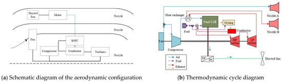
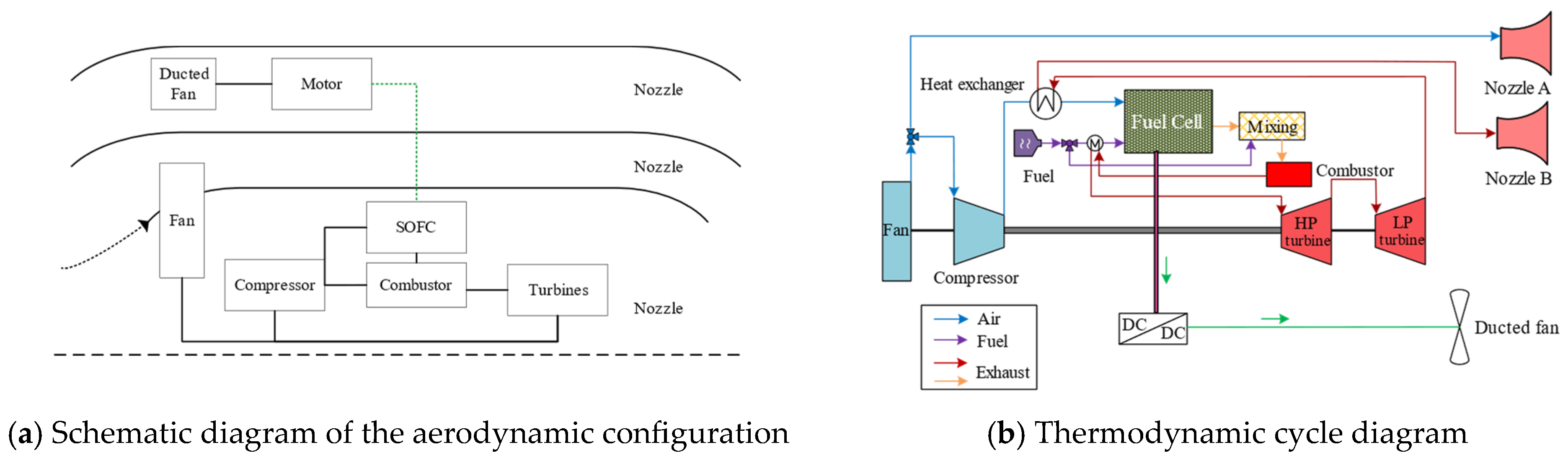
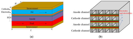
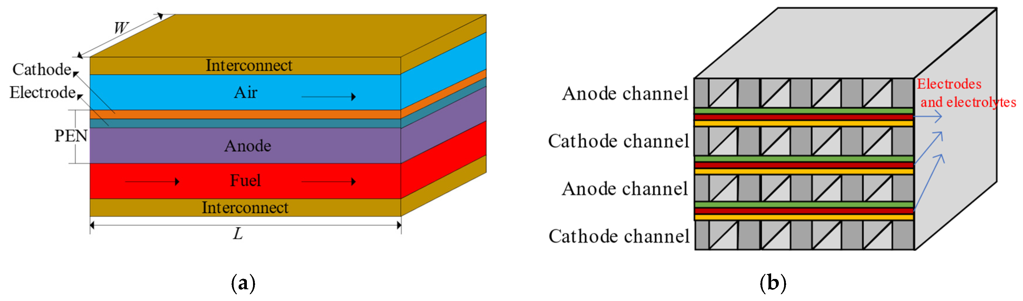
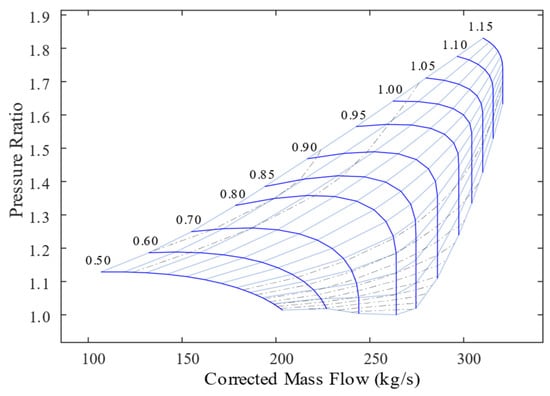
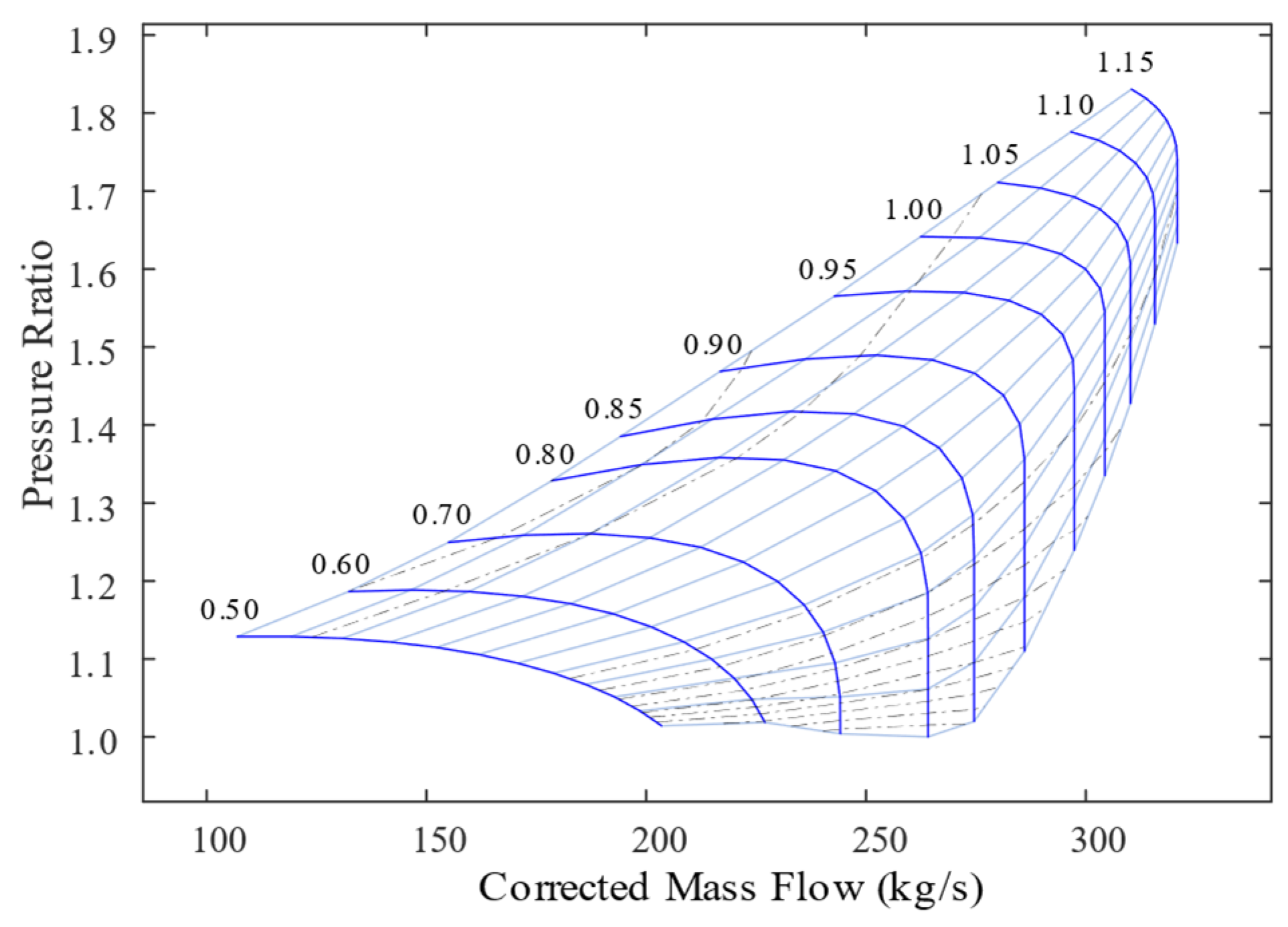
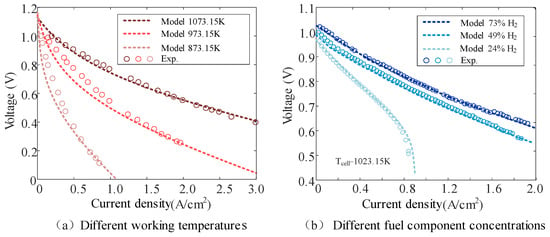
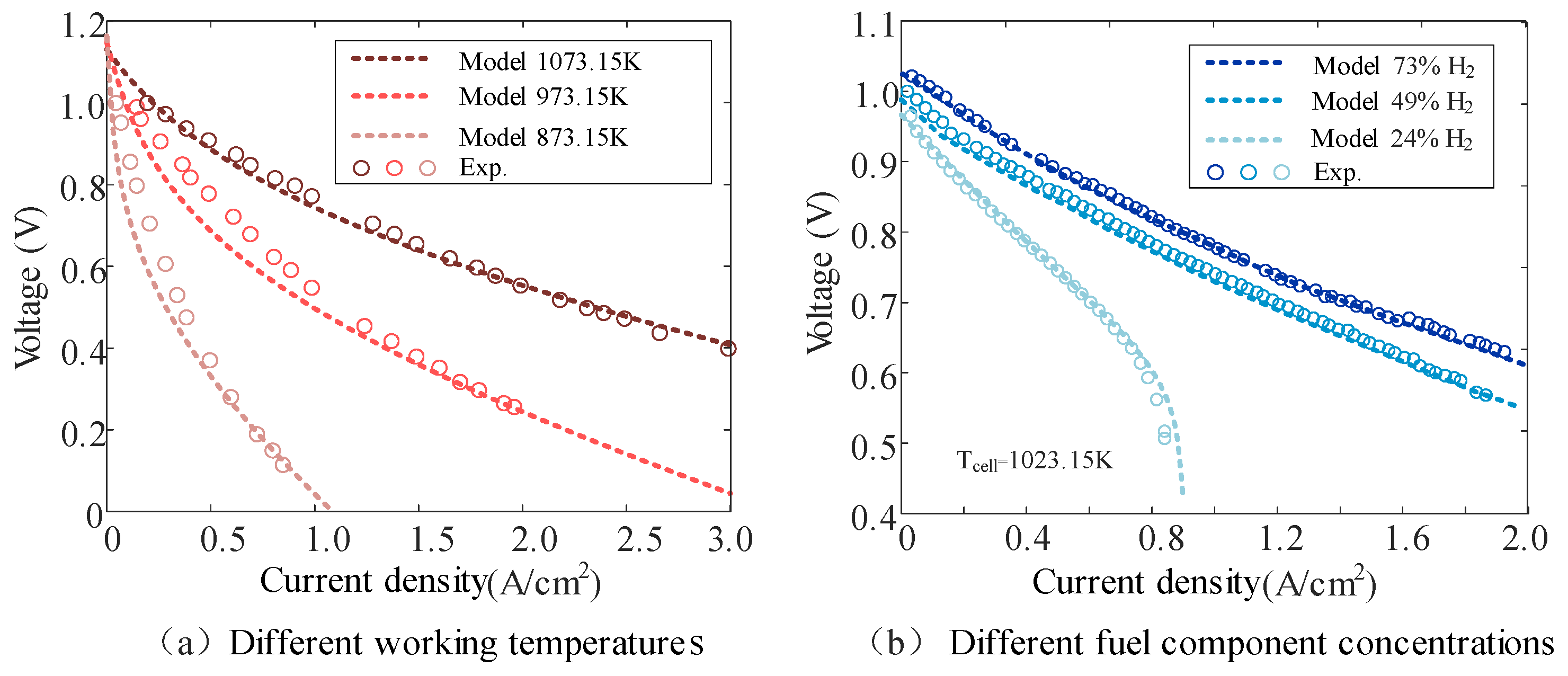
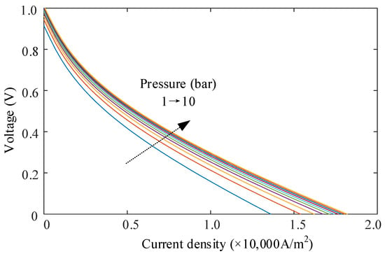
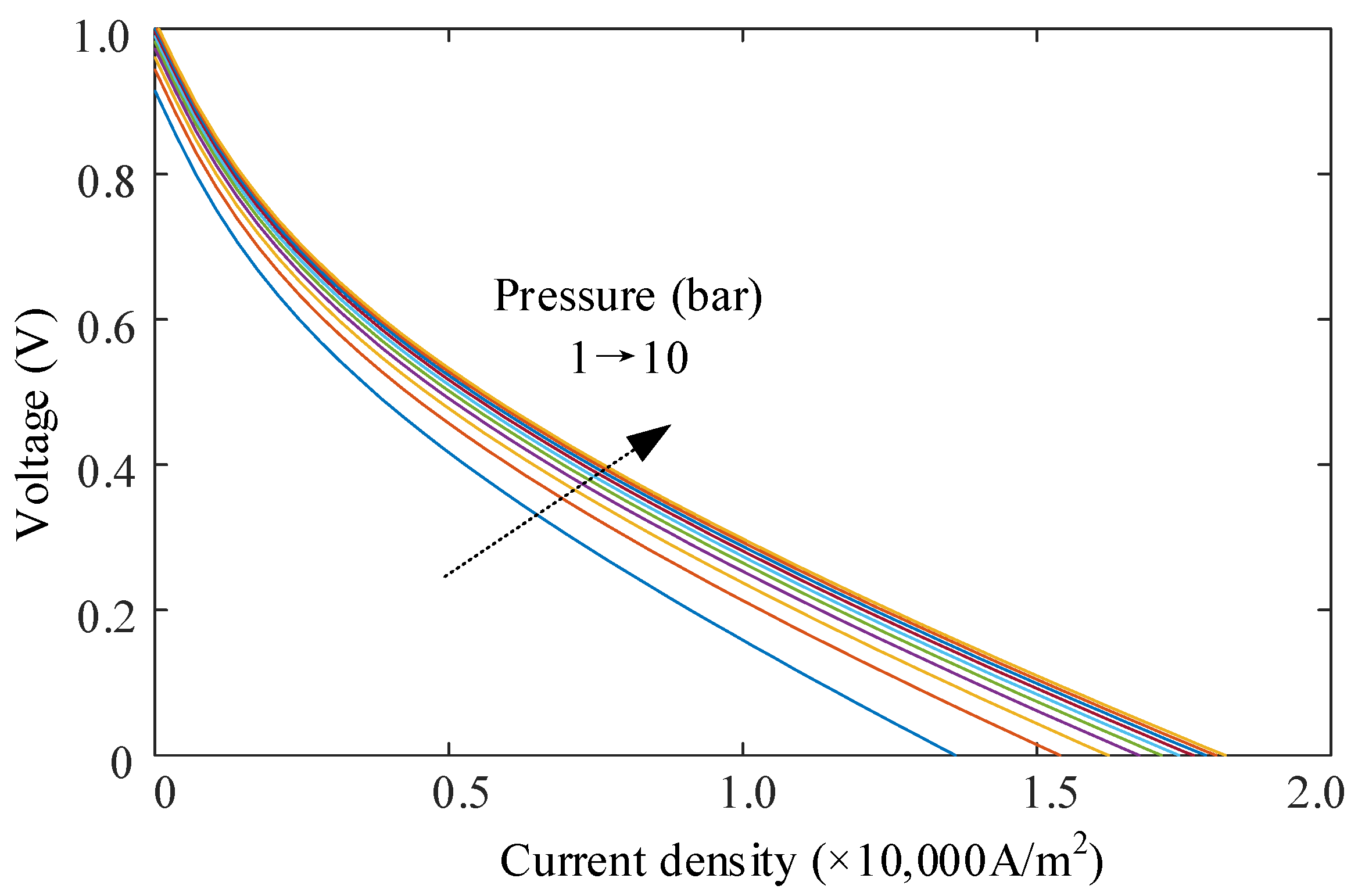
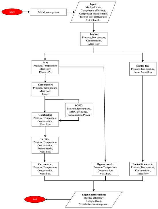
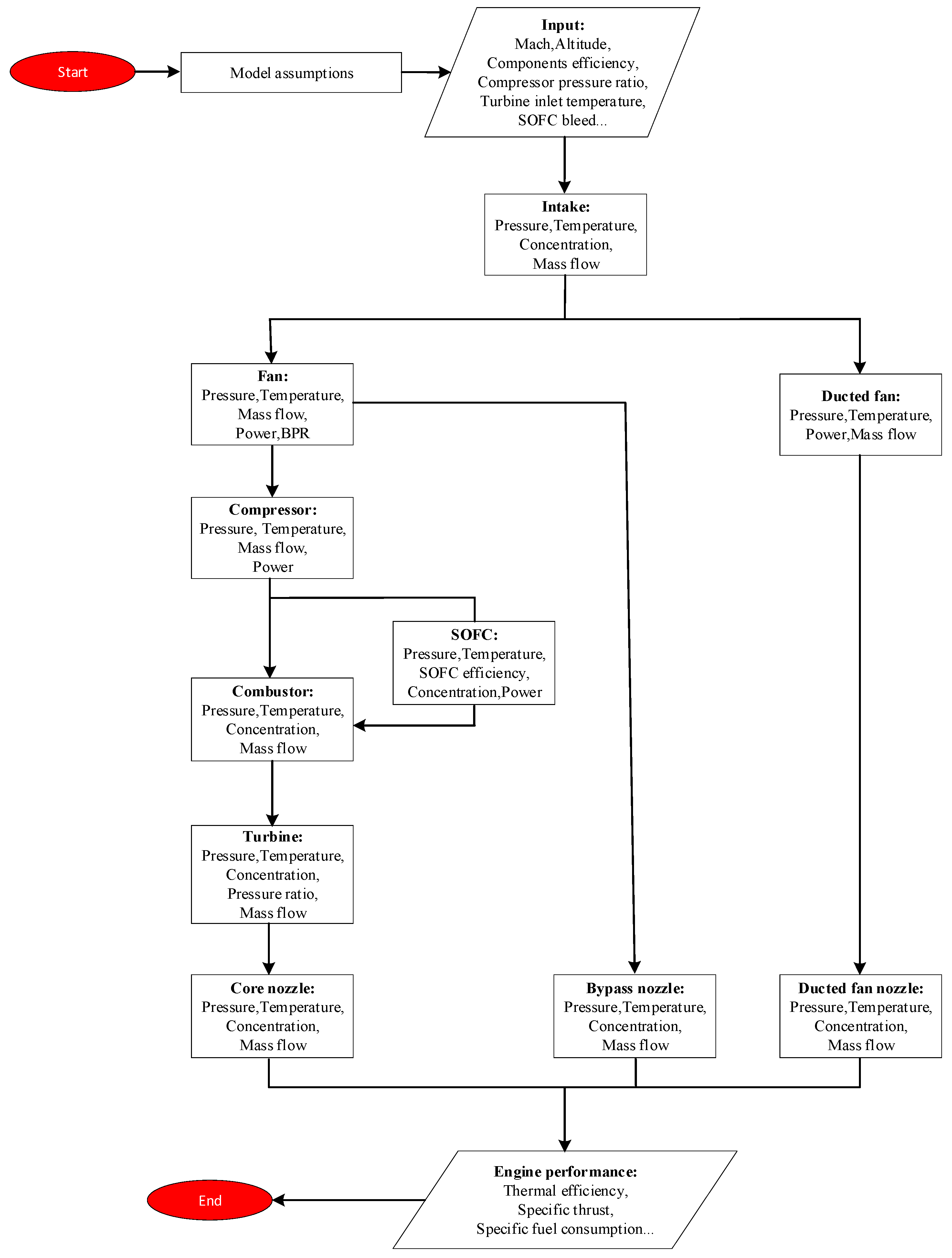
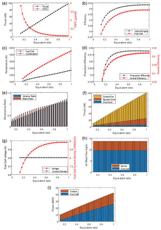
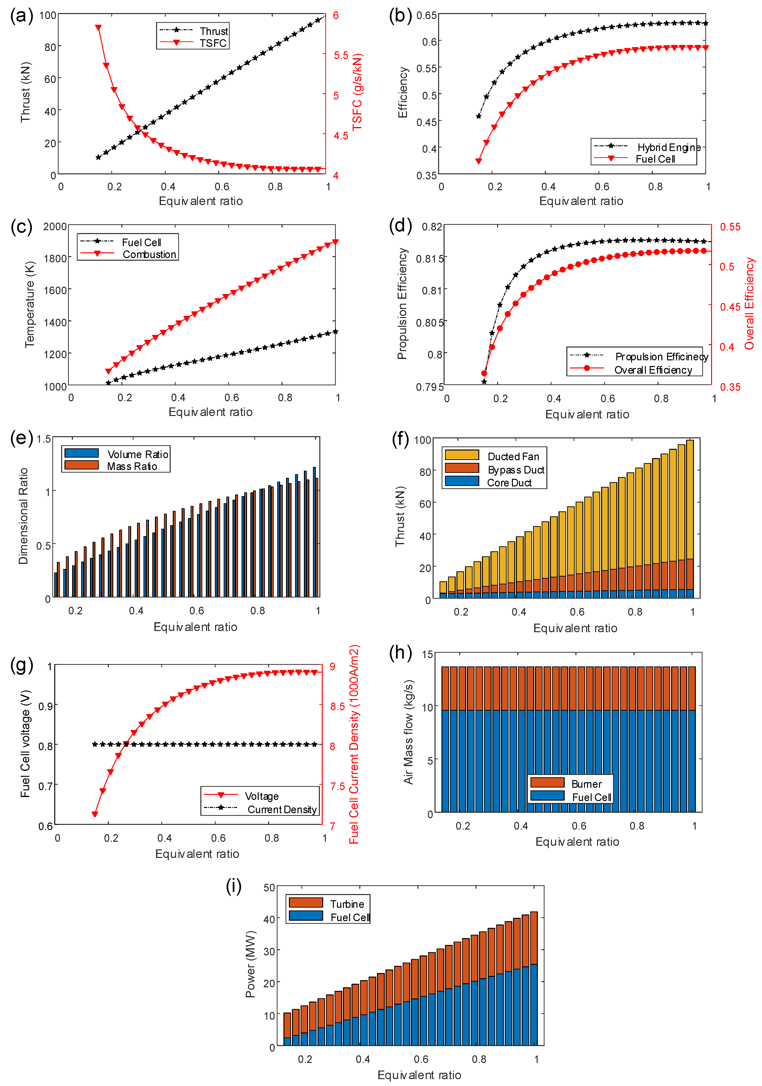
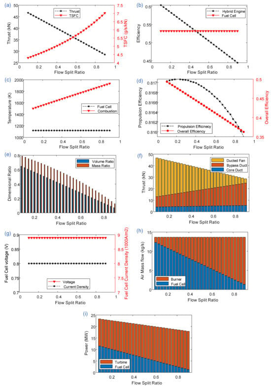
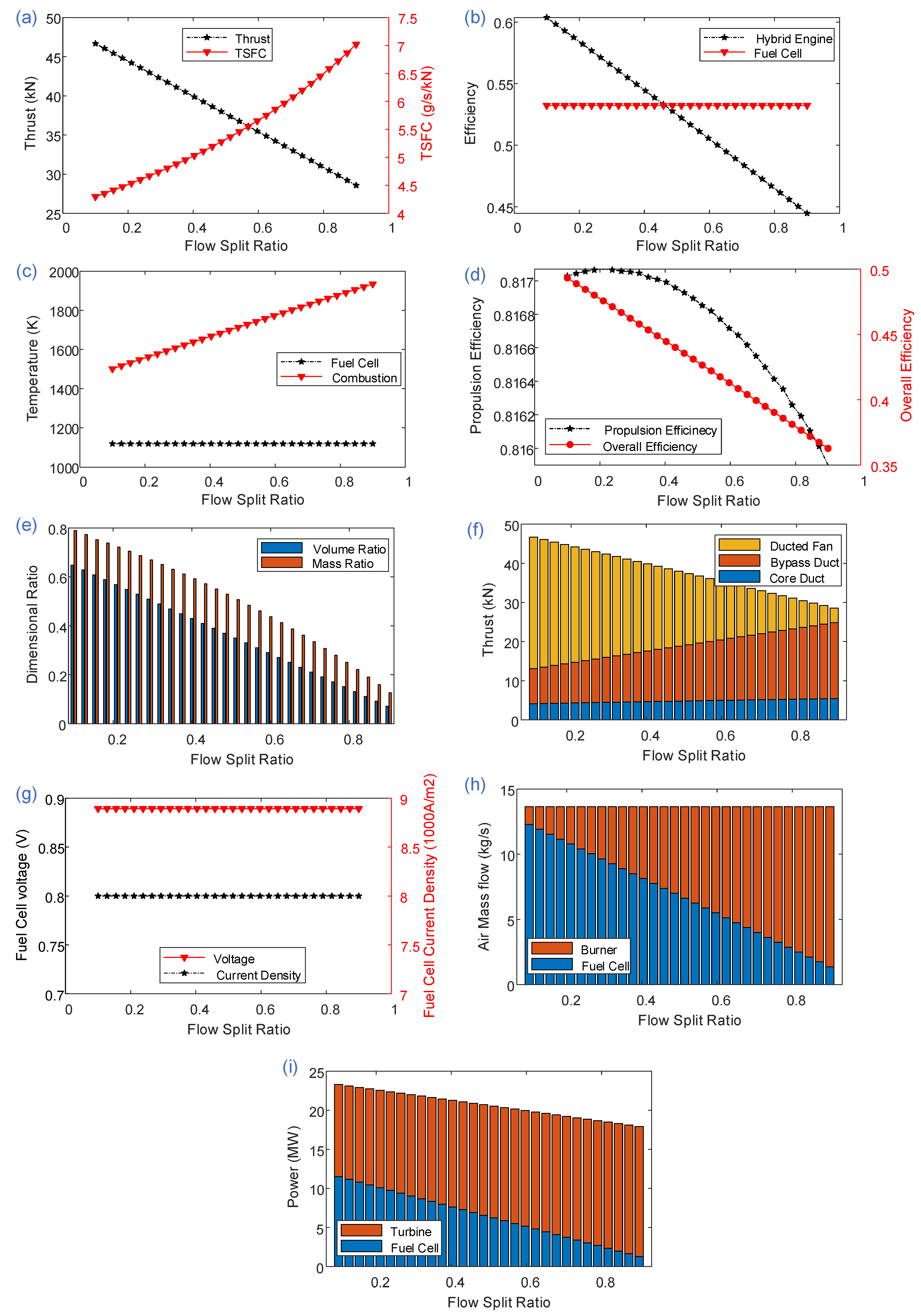
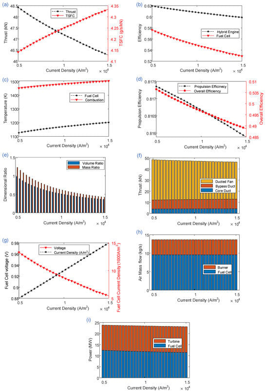
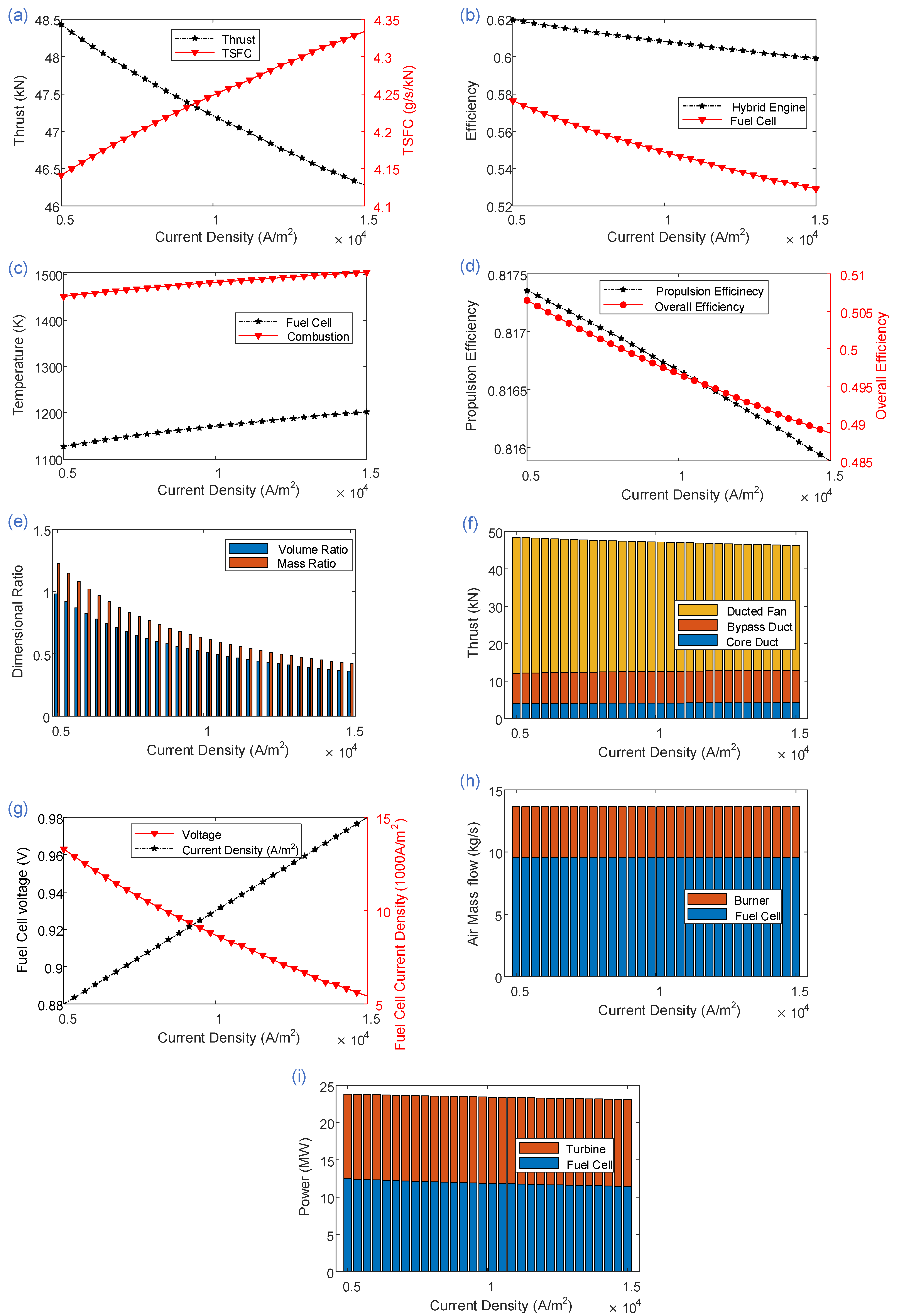
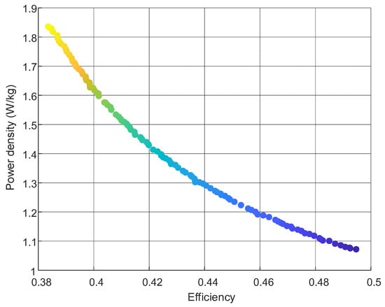
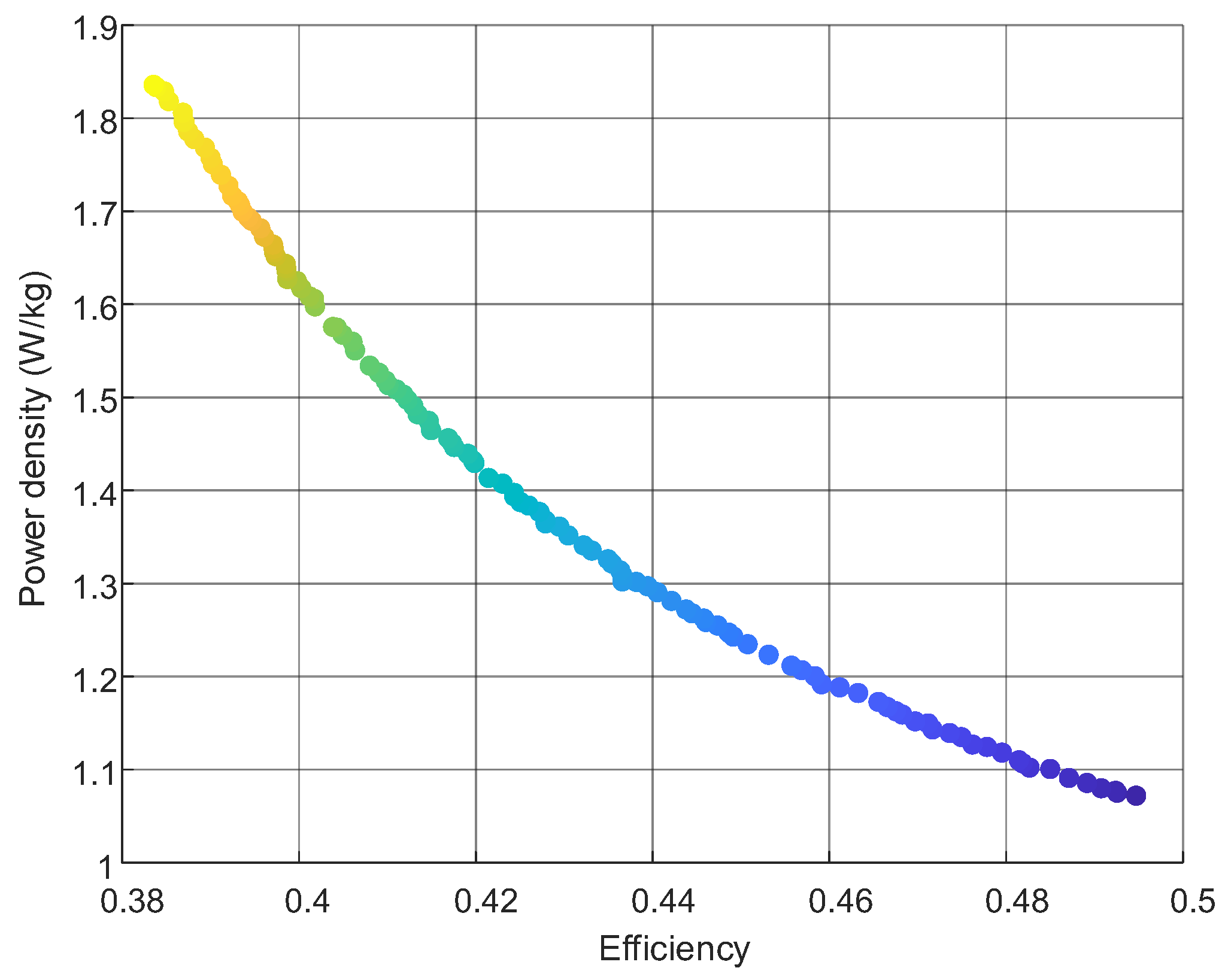
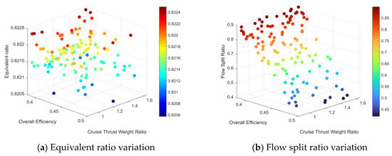
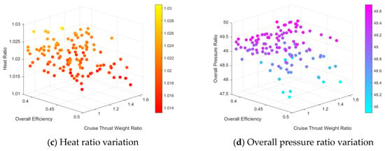
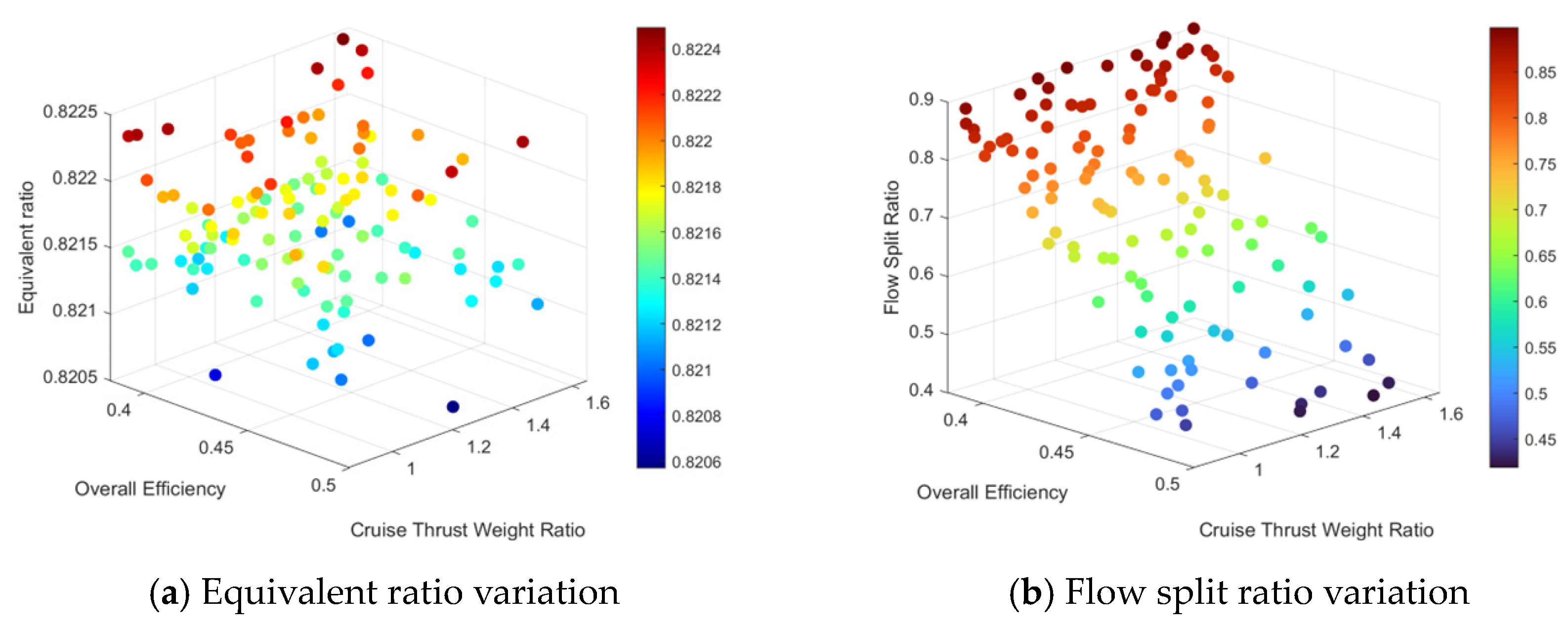
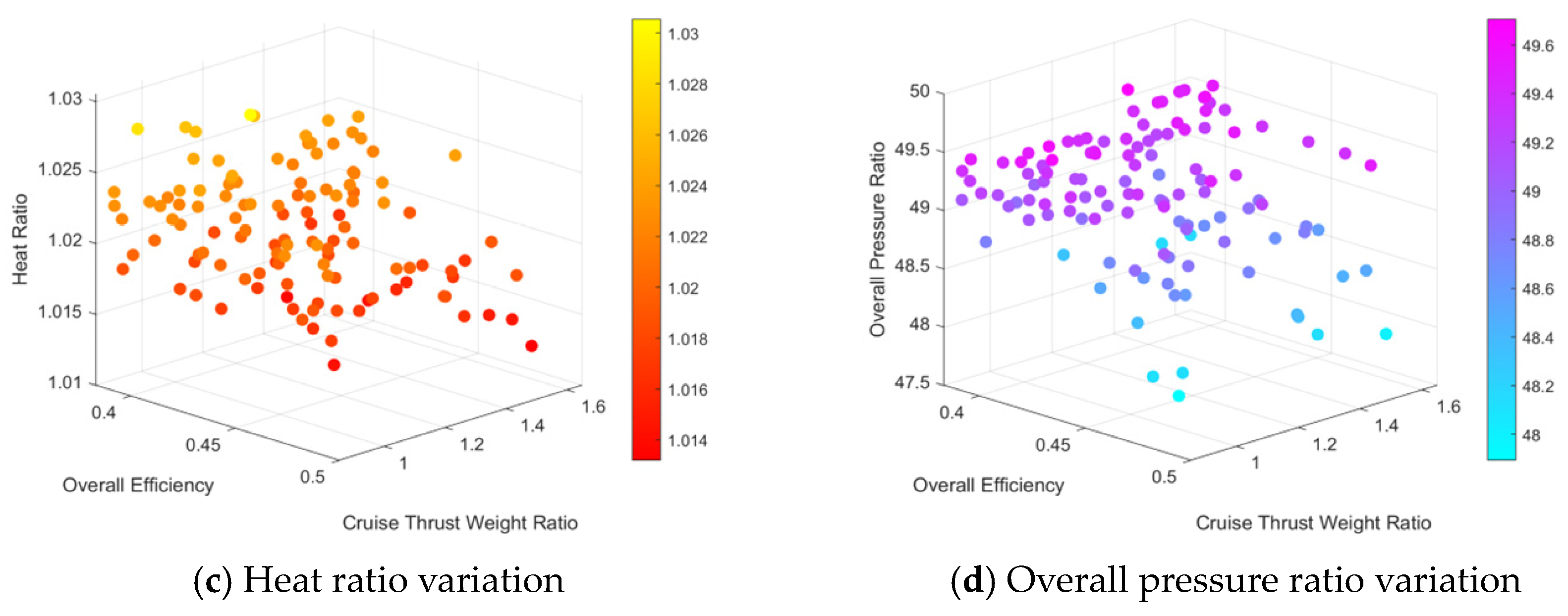
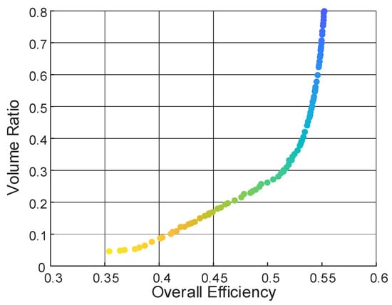
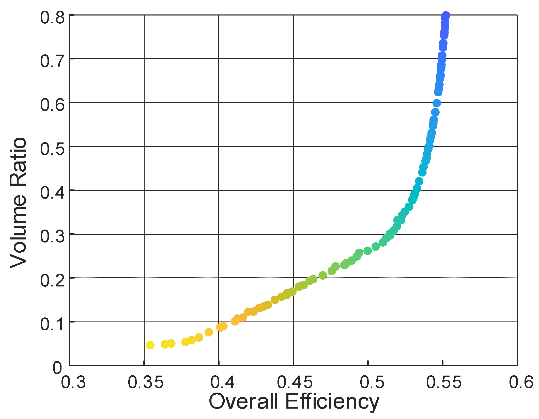
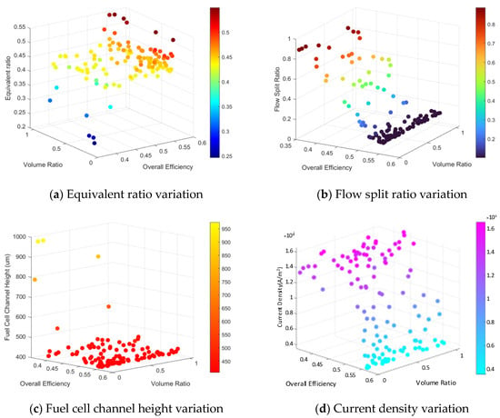
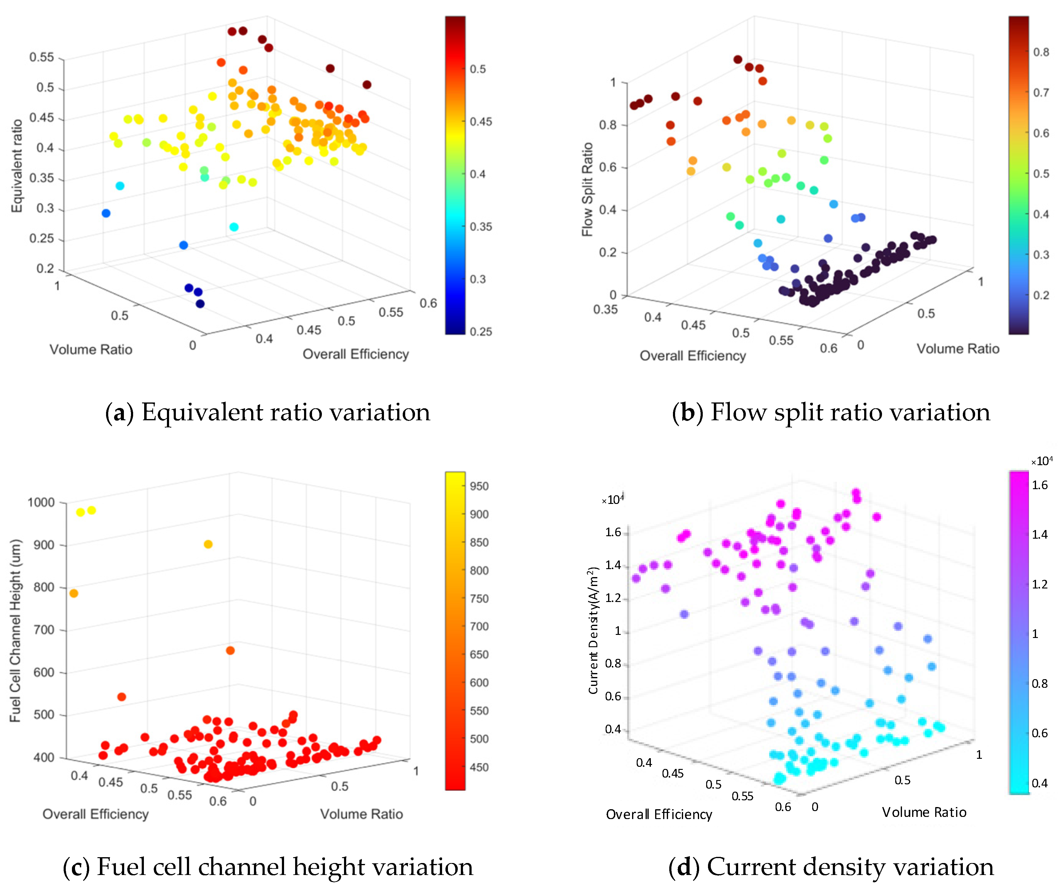
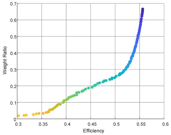
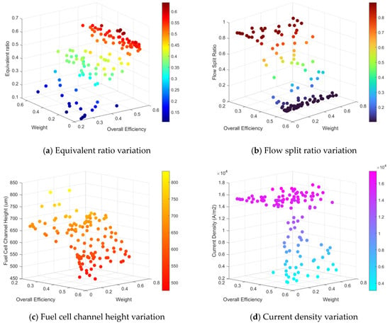
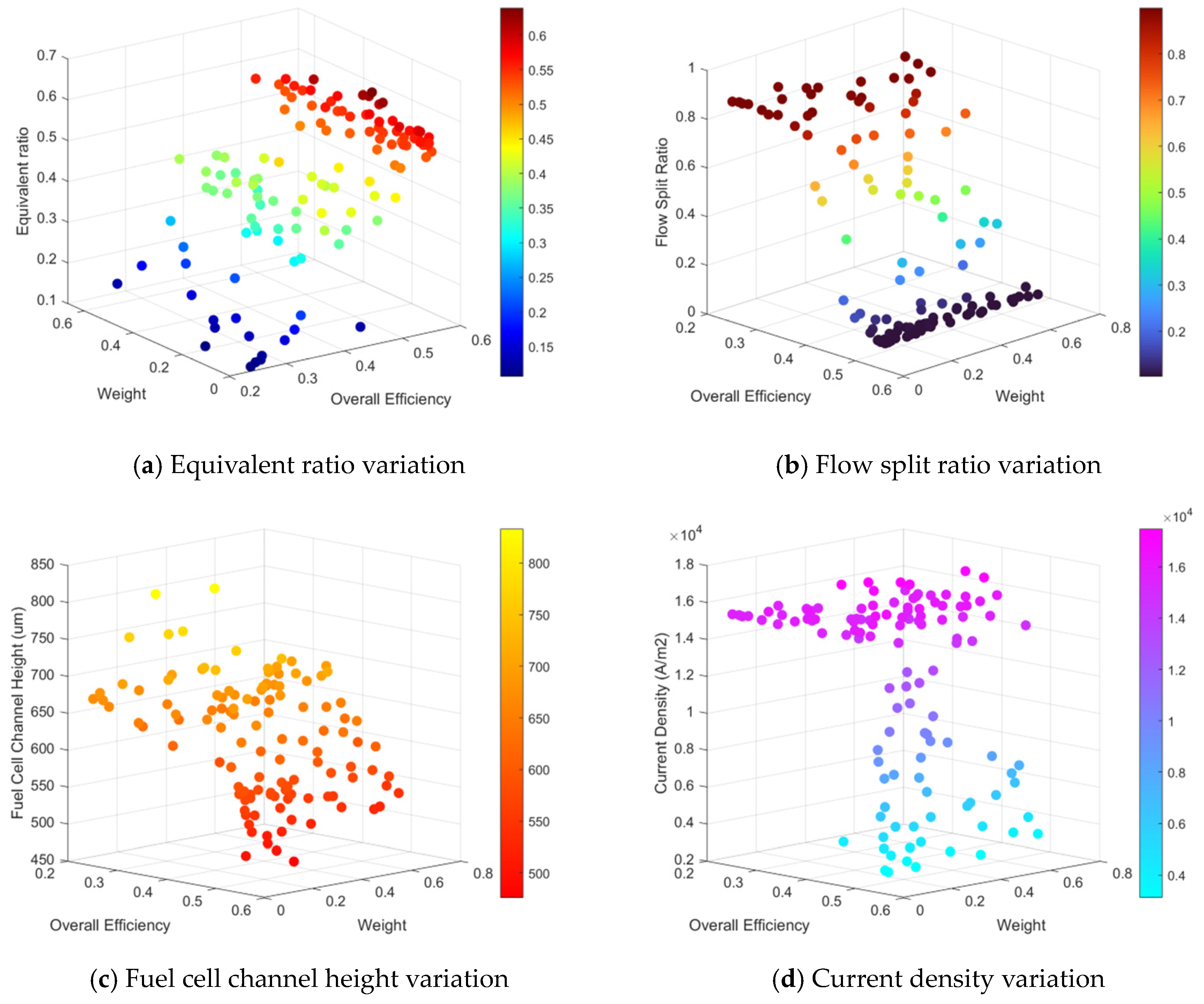
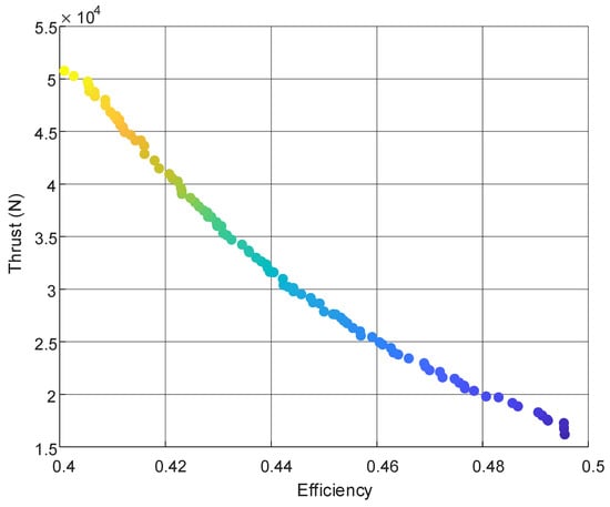
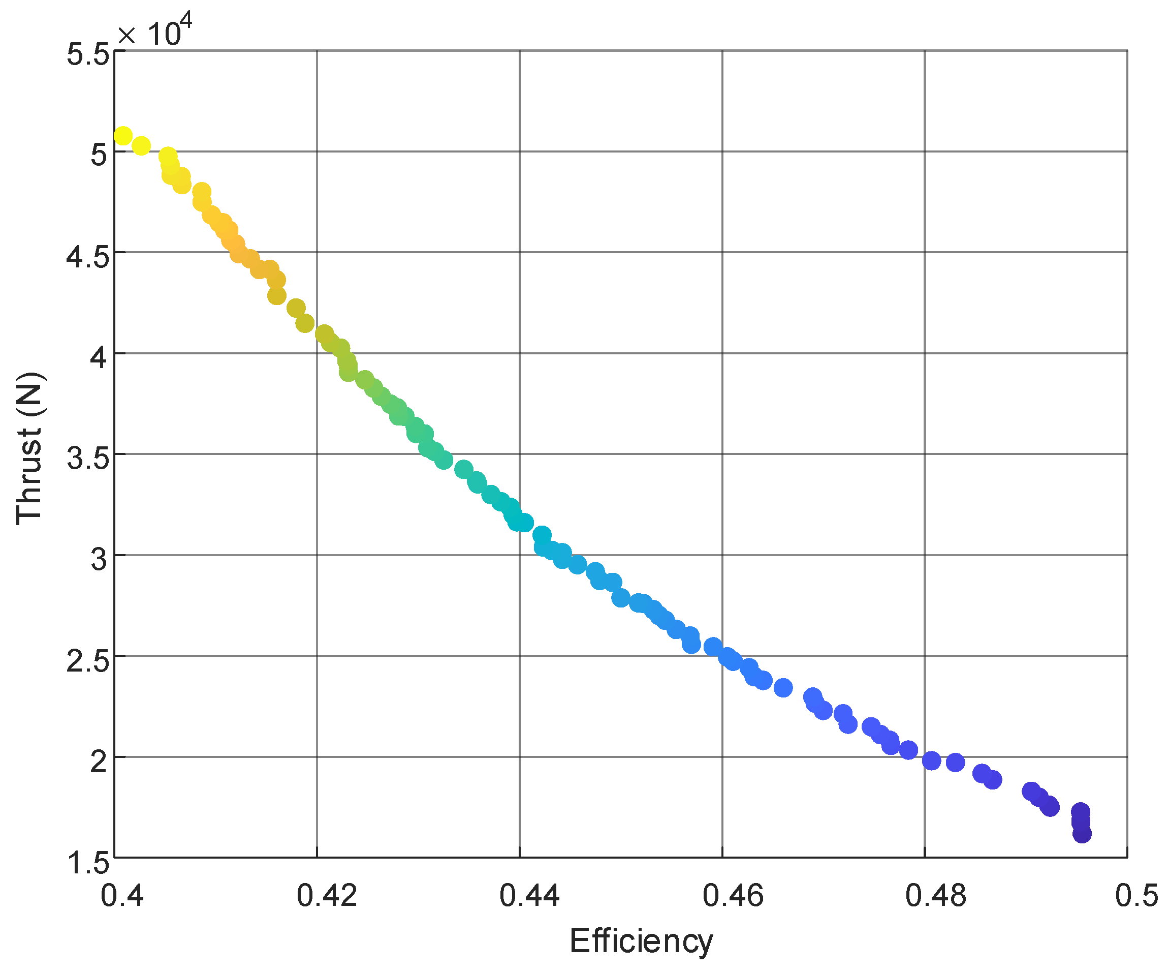
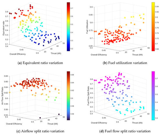
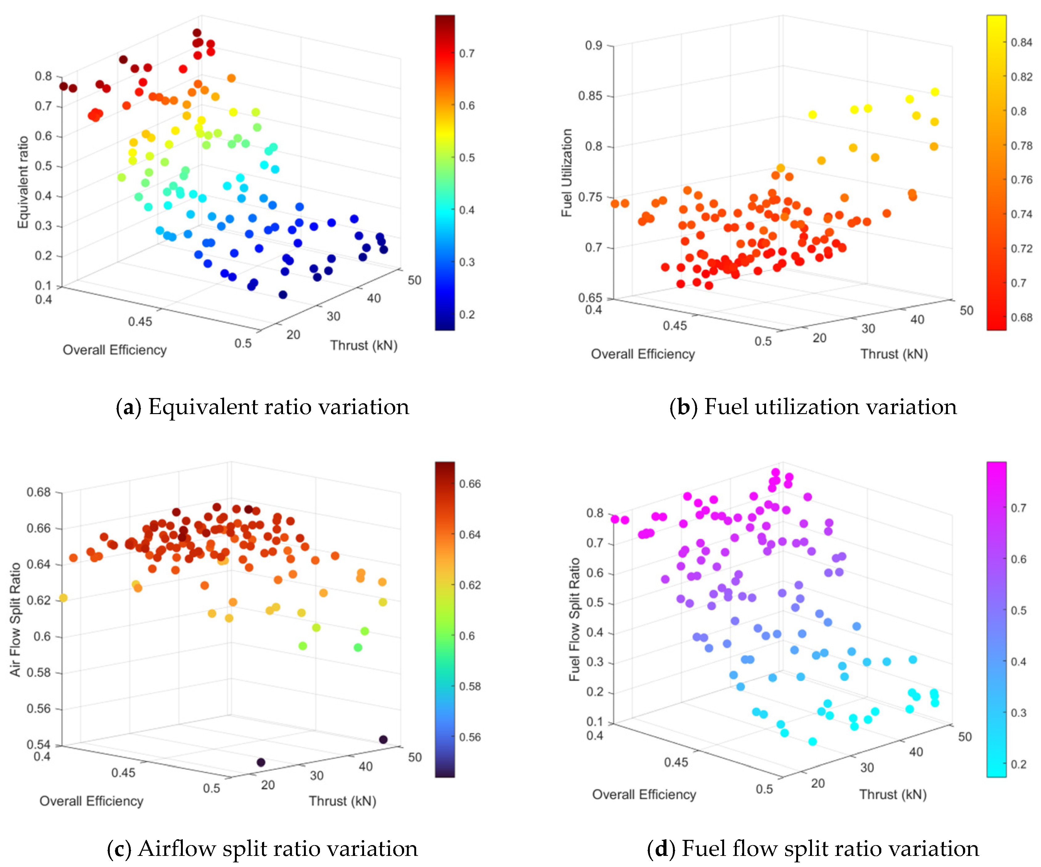

Disclaimer/Publisher’s Note: The statements, opinions and data contained in all publications are solely those of the individual author(s) and contributor(s) and not of MDPI and/or the editor(s). MDPI and/or the editor(s) disclaim responsibility for any injury to people or property resulting from any ideas, methods, instructions or products referred to in the content. |
© 2026 by the authors. Licensee MDPI, Basel, Switzerland. This article is an open access article distributed under the terms and conditions of the Creative Commons Attribution (CC BY) license.