


Abstract
Wide- and narrow-band composite-axis servo systems in inter-satellite laser communication face critical challenges in balancing high-precision dynamic tracking and strong robust anti-disturbance performance under the coupling effect of high-speed inter-satellite relative motion and multiple strong disturbances. To address this issue, this paper proposes a composite control method integrating adaptive non-singular terminal sliding-mode control and a nonlinear extended state observer. First, a full-link dynamic model covering electromechanical coupling and inter-axis disturbance transmission is constructed to accurately quantify the disturbance characteristics of coarse- and fine-tracking loops. Second, a third-order nonlinear extended state observer is designed to realize real-time high-precision estimation and feedforward compensation of lumped disturbances. On this basis, a self-consistent adaptive non-singular terminal sliding-mode control law is formulated. Under the explicitly stated observer-residual and reaching-phase assumptions, the ideal continuous model provides finite-time convergence of the sliding variable and tracking error. Finally, a wide- and narrow-band cooperative strategy based on error frequency division is introduced to achieve complementary performance between large-stroke coarse tracking and ultra-high-precision fine tracking. Numerical simulations yield a steady-state tracking-error point estimate of 0.30 μrad and a 20 dB disturbance-suppression bandwidth of 1200 Hz. In the semi-physical dynamic-tracking test, the proposed controller limits the peak error to 1.2 μrad; the instrument-only expanded uncertainty of the detector output is estimated as 0.12 μrad (coverage factor k = 2). At the reported evaluation points, the proposed method outperforms PID, conventional sliding-mode control, and linear active-disturbance-rejection control. Deterministic robustness simulations also show smaller tracking errors and shorter recovery times under parameter perturbation, actuator saturation, and temporary link occlusion. No Monte Carlo loss-of-lock probability is claimed.
1. Introduction
With the large-scale construction of the integrated space–ground information network, inter-satellite laser communication has become the core supporting technology for space information transmission, with its core advantages of large bandwidth, high confidentiality, and low power consumption. The high-precision composite-axis pointing, acquisition, and tracking (PAT) system is the core unit to ensure the stable establishment and continuous maintenance of inter-satellite laser links. Its dynamic tracking performance and anti-interference ability directly determine the reliability and communication quality of space laser communication.
Extensive research has been carried out on composite-axis PAT systems from the perspectives of architecture design, on-orbit verification, and engineering application.
Ding et al. [1] designed and validated a high-precision composite-axis PAT system for inter-satellite dynamic laser communication scenarios, confirming the tracking performance advantages of the composite-axis architecture in dynamic scenarios and providing core references for system infrastructure design. Yu et al. [2] conducted in-orbit experiments on inter-satellite laser communication based on composite-axis tracking and verified the engineering applicability of the architecture through in-orbit measurement data. They also pointed out that there is still significant room for optimization of the system’s tracking accuracy under in-orbit micro-vibration disturbances. Toyoshima et al. from JAXA completed an on-orbit demonstration of laser communication between low-orbit satellites and ground stations, and they verified the long-term operational stability of the composite-axis fine-tracking mechanism in the space environment. Zhao et al. [3] conducted experimental research on a beacon-free inter-satellite laser communication tracking system based on direct fiber-optic control, expanding the application boundaries of composite-axis tracking systems and reflecting the dynamic response shortcomings of traditional tracking strategies in beacon-free and low signal-to-noise ratio scenarios. Wang et al. [4] completed the prototype development of a spatial multi-node laser communication network’s multi-target tracking system, verified the adaptability of the composite-axis system in multi-target scenarios, and also exposed the matching contradiction between system bandwidth and tracking accuracy in multi-node dynamic scenarios.
From the perspective of control algorithm optimization, scholars have carried out a lot of research on improving tracking accuracy and disturbance suppression capabilities.
Lv et al. [5] conducted a special study on the bandwidth improvement of a precision-tracking control system for space laser communication and clarified that the bandwidth of the precision-tracking loop is the core indicator that determines the high-frequency disturbance suppression ability of the system, which points out the core direction for the optimization of the precision-tracking control link. Cao et al. [6] proposed an improved steady-state tracking strategy for the composite-axis system of free-space laser communication, effectively optimizing the steady-state tracking accuracy of the system. However, the adaptability to dynamic tracking and sudden disturbance scenarios still needs to be improved. Sun et al. [7] conducted research on the high-precision tracking problem of free-space optical communication systems on mobile platforms, and they verified the effectiveness of advanced control methods in dynamic platform scenarios, providing a method reference for tracking control in inter-satellite dynamic scenarios. Dhruv et al. [8] systematically reviewed the research progress of non-ground-platform free-space optical communication pointing modules and gimbal systems, comprehensively summarized the technical advantages and existing bottlenecks of composite-axis systems, and clarified that active anti-interference ability in strong disturbance and high-dynamic scenarios is the core direction of current technological breakthroughs.
In terms of active disturbance rejection control and dual-loop collaborative design, related studies have also made staged progress.
Wang et al. [9] designed an airborne laser target dynamic tracking system based on an inertial reference unit, achieving stable tracking on a dynamic platform. The design concept of inertial feedforward compensation provides a technical reference for optimizing inter-satellite dynamic tracking systems. Han et al. [10] proposed a high-precision control strategy for the ultra-low-speed and variable-speed motion characteristics of satellite platform pointing mechanisms, effectively suppressing tracking errors caused by mechanism nonlinearity and providing methodological support for high-precision closed-loop control of composite-axis system actuators. Zhang et al. [11] conducted a systematic review of the relative state measurement technology for precision formation of distributed spacecraft, clarifying that the inter-satellite relative dynamic characteristics are the core input for the design of tracking and aiming systems and providing a theoretical basis for the construction of dynamic tracking and aiming strategies. Wu et al. [12] proposed a single detector composite-axis system using biaxial mirrors to achieve target capture, optimizing the optical architecture and capture performance of the system. At the same time, higher requirements were put forward for the collaborative control of biaxial wide- and narrow-band circuits. Heine et al. from DLR applied linear active disturbance rejection control to the fine steering mirror control of space laser communication terminals, which improved the system’s ability to suppress micro-vibrations. However, the linear observer has limited estimation accuracy for nonlinear fast-varying disturbances. Li [13] developed a computer-vision-assisted laser communication tracking system integrating a lightweight convolutional neural network with Kalman filtering and closed-loop beam steering, demonstrating the potential of intelligent methods for robust real-time optical alignment in dynamic environments. Although such approaches improve tracking adaptability, their computational requirements and deployment constraints remain important considerations for resource-limited spaceborne platforms. Wang et al. [14] conducted research on the principle, integrated design, and control method of a damping positioning mechanism for segmented mirror systems. Their high-precision mechanism collaborative control approach provides a reference for optimizing the actuator of composite-axis systems. Li et al. [15] reviewed the application progress of rotating Risley prisms in space optics, expanded the technical route of space optical tracking mechanisms, and further reflected that the dynamic adaptability and active anti-interference ability of traditional composite-axis systems in high dynamic scenarios still need systematic breakthroughs.
In summary, existing research has laid a solid foundation for the development of composite-axis tracking systems [16]. However, there are still three main shortcomings. First, most dynamic models adopt independent modeling of coarse and fine loops, ignoring the quantitative characterization of inter-axis coupling disturbance transmission characteristics, which reduces the accuracy of the model basis for controller design. Second, a single control method finds it difficult to balance the requirements of finite-time convergence, chattering suppression, and disturbance suppression. Traditional sliding-mode control has serious chattering, and linear active disturbance rejection control has limited estimation ability for nonlinear fast-varying disturbances. Third, the collaborative design of wide- and narrow-band loops is insufficient. The matching relationship between dual-loop bandwidths and disturbance suppression frequency bands is not clear, which easily leads to control frequency band overlap and disturbance suppression blind spots. It is still difficult to simultaneously meet the dual requirements of high-precision dynamic tracking and strong robust active disturbance rejection in real space scenarios.
In response to these limitations, this study proposes a high-precision dynamic-tracking and active-disturbance-rejection method for the wide- and narrow-band composite-axis servo system used in inter-satellite laser communication. The main contributions are as follows: (1) a physically separated model of mechanical inter-axis coupling and optical detector displacement is established; (2) a nonlinear extended state observer is combined with a self-consistent adaptive non-singular terminal sliding-mode controller, and the scope of its stability claim is stated explicitly; (3) complementary frequency-division filters and platform-specific bandwidth-selection rules are defined for coordinated coarse- and fine-loop control.
2. System Modeling and Control Method Design
2.1. Coupling Dynamics Modeling of Wide- and Narrow-Band Composite-Axis Servo Systems
2.1.1. Overall Working Principle and System Architecture
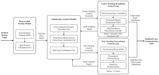
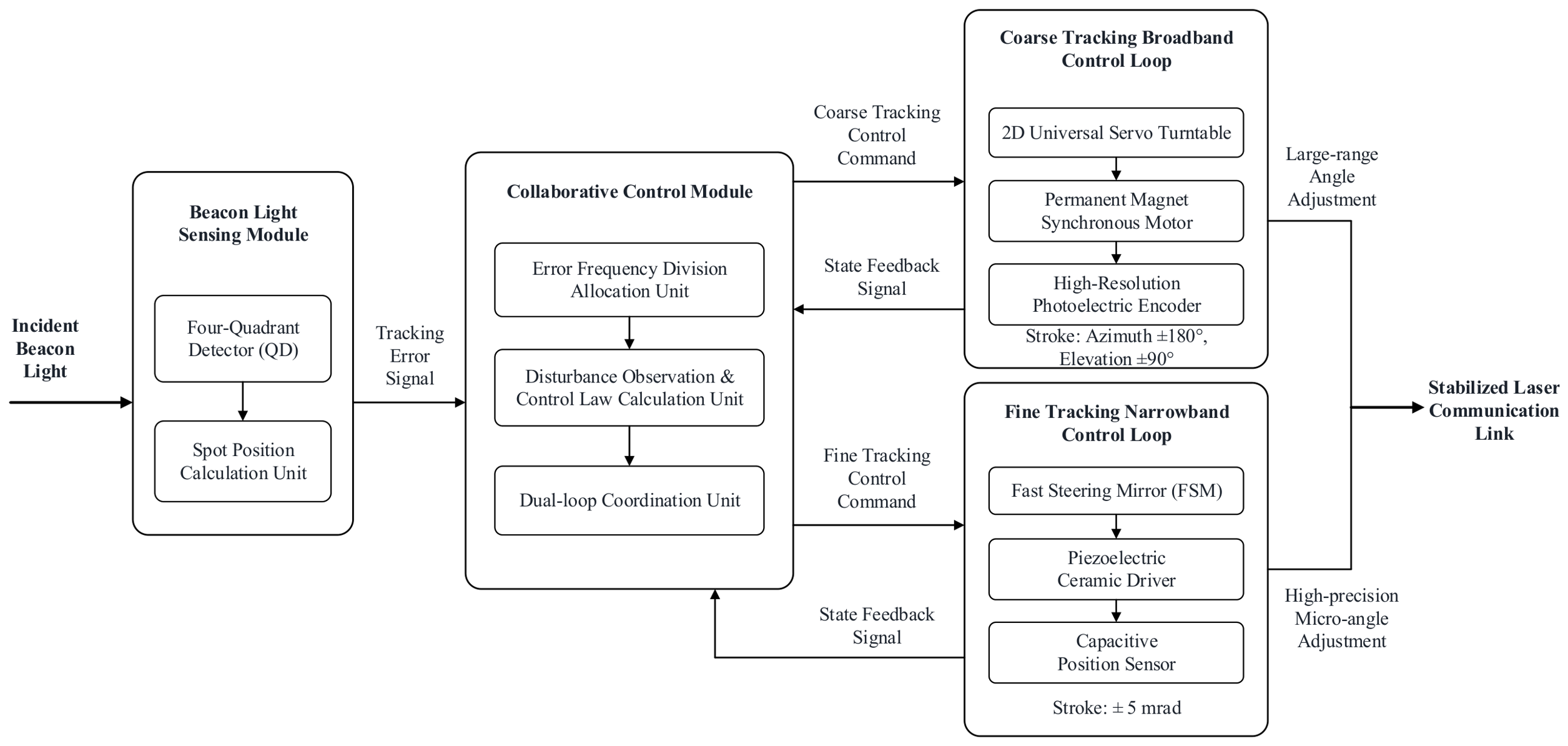
The core function of the wideband composite-axis servo system for inter-satellite laser communication is to achieve the capture, alignment, and tracking of beacon light through the collaborative work of coarse and fine dual circuits, ensuring the continuous stability of the laser communication link. The overall architecture diagram of the system is shown in Figure 1.
Figure 1.
Overall architecture of narrow- and wide-band composite-axis servo system for inter-satellite laser communication.
As shown in Figure 1, the system is divided into four core modules: beacon light sensing module, coarse-tracking broadband control loop, fine-tracking narrowband control loop, and collaborative control module. Among them, the beacon light sensing module collects the beacon light emitted by the opponent’s satellite through a four-quadrant detector (QD), calculates the spot position’s deviation in real time, and outputs a tracking error signal. The coarse-tracking broadband loop is composed of a two-dimensional universal servo turntable, a permanent magnet synchronous motor, and a high-resolution photoelectric encoder. It is responsible for coarse capture of beacon light and low-frequency large-scale disturbance suppression within the ±180° azimuth and ±90° elevation range, and it is the main broadband control body of the system. The system consists of a precision-tracking narrow-loop routing fast tilt mirror (FSM), piezoelectric ceramic driver, and capacitive position sensor, and it is responsible for sub-micro-arc high-precision tracking and high-frequency micro-amplitude disturbance suppression within a range of ±5 mrad. It is the narrow-band high-precision control core of the system. The collaborative control module receives tracking errors and feedback signals from the dual-loop state; completes disturbance observation, control law calculation, and instruction allocation; and achieves collaborative control and coupling suppression of the dual loop.
2.1.2. Coarse-Tracking Broadband-Loop Dynamics
As the large-stroke execution unit of the system, the core of the coarse-tracking loop is the rigid-body rotation system of the two-dimensional servo turntable, which needs to consider both the electromagnetic characteristics of the motor and mechanical transmission characteristics. Establish a unified electromechanical coupling dynamic equation for the two independent motion axes of azimuth and elevation:
In the formula, is the moment of inertia of the coarse-tracking axis, is the viscous friction coefficient, is the torsional stiffness coefficient, is the rotation angle of the turntable, is the motor torque coefficient, is the motor armature current, is the external disturbance torque, and is the coupling disturbance torque between the coarse and fine axes.
In this equation, the external disturbance torque and inter-axis coupling torque are load torques opposite to the driving direction. They hinder the rotation of the turntable, so they are subtracted from the driving torque term in the torque balance equation.
2.1.3. Fine-Tracking Narrow-Band Loop Dynamics
The fine-tracking loop is the core unit that determines pointing accuracy. Its fast-steering mirror (FSM) is driven by a piezoelectric actuator and is modeled with inertia, damping, flexure stiffness, parameter perturbations, external disturbance torque, and the mechanical coupling torque transmitted from the coarse loop [17,18]:
Here, , , and are the nominal FSM inertia, damping, and flexure-stiffness coefficients; , , and are their perturbations; is the FSM deflection; is the unloaded angular sensitivity of the piezoelectric/FSM actuator (rad V−1); is therefore the torque-to-voltage gain (N·m V−1); is the control voltage; is the external disturbance torque; is the mechanical coupling torque from the coarse loop.
The two disturbance terms in Equation (2) are defined as torques acting on the FSM. Their signs are positive in the chosen input convention; restoring, damping, and parameter-perturbation contributions are retained on the left-hand side and are transferred consistently to the lumped acceleration disturbance in Equation (4).
2.1.4. Disturbance-Transfer Modeling for Dual-Loop Coupling
Coarse-axis errors affect the fine loop through two physically distinct channels: an optical mapping to the quadrant-detector (QD) image plane and a mechanical torque transmitted through the mounting structure. These channels are written separately as
In Equation (3), is the QD spot-position displacement, (m rad−1) is the calibrated angle-to-image displacement sensitivity, is the mechanical coupling torque, (N·m rad−1) is the equivalent angular-stiffness coupling coefficient, and (kg·m2) is the equivalent inertial-coupling coefficient. The quantity d_couple is defined as and therefore represents a mechanical coupling torque with units of N·m. The optical sensitivity is obtained by optical calibration, whereas the mechanical coupling coefficients and are identified from the mechanical response of the platform.
For controller design, the mechanical coupling torque, external torque, and parameter perturbations are collected in a lumped acceleration disturbance. With and , Equation (2) becomes [19]
The nominal term contains damping and elastic restoring effects with their physical negative signs, b has units of rad s−2 V−1, and D(t) has units of rad s−2. This definition corrects the former control-gain dimension and the signs of the and contributions.
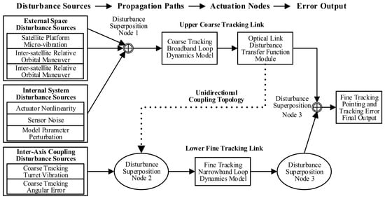
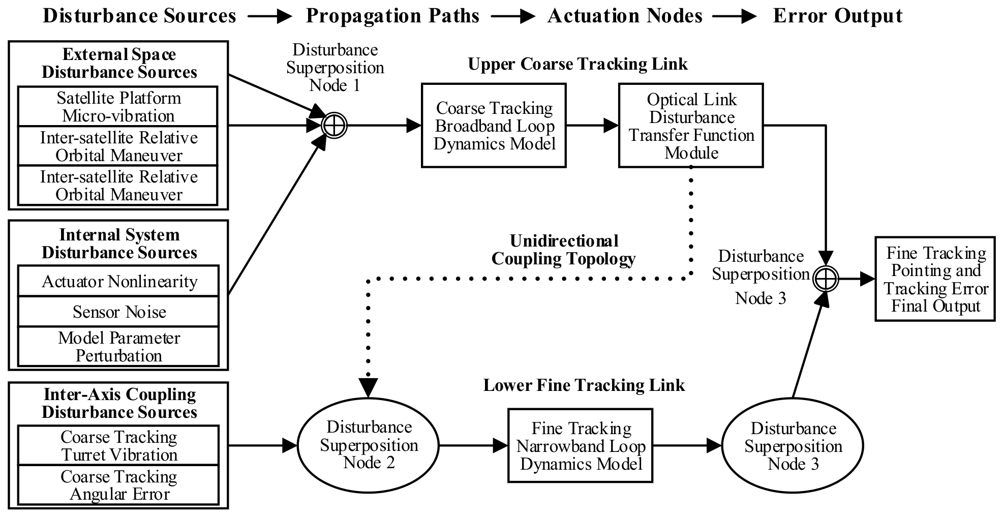
The corresponding disturbance transmission and coupling relationships are summarized in Figure 2.
Figure 2.
Relationship between disturbance transmission and coupling characteristics in the wide- and narrow-band composite-axis system.
As shown in Figure 2, external disturbances include satellite-platform micro-vibrations, inter-satellite relative motion, and environmental loads. Internal disturbances include actuator nonlinearity, sensor noise, and model-parameter perturbations. Coarse-axis effects reach the fine loop through the optical measurement channel and the mechanical coupling torque [20].
Figure 2 contains three disturbance-superposition nodes (Nodes 1–3). Their functions are as follows:
Node 1: The coarse-loop input node, which combines motor drive torque with external and load torques in the balance expressed by Equation (1).
Node 2: The inter-axis coupling node, which maps coarse-axis angular errors to QD image displacement and transfers the identified mechanical coupling contribution in Equation (3).
Node 3: The fine-loop input node, which combines control torque, external disturbance torque, and mechanical coupling torque in Equation (2).
Model Assumptions and Validity. The coupling model is based on the following assumptions and application scope:
(1) Physical Assumptions. The coarse-tracking turntable is treated as a rigid body, and structural flexibility is ignored. This assumption is valid below the first structural natural frequency (<100 Hz). The piezoelectric actuator is assumed to operate in its calibrated linear region, and the flexure hinge is assumed to exhibit small-deformation linear elasticity within the ±5 mrad deflection range.
Inter-axis mechanical coupling is treated as predominantly unidirectional from the coarse loop to the fine loop. Reaction from the fine loop is neglected because its moment of inertia is approximately three orders of magnitude smaller than that of the coarse loop.
(2) Parameter Sources. Coarse-loop parameters are obtained from electromechanical measurements of the two-dimensional servo turntable. Fine-loop parameters are taken from piezoelectric-FSM calibration and system-identification results. The optical sensitivity G_θ and mechanical coupling coefficients and must be obtained by optical calibration and mechanical identification, respectively.
(3) Unit Consistency. All physical quantities adopt the International System of Units (SI), with angles in rad, torque in N·m, voltage in V, and moment of inertia in kg·m2.
(4) Validity Range. The model applies to low-orbit inter-satellite laser-communication scenarios over , disturbance frequencies of , and tracking angular velocities not exceeding . The rigid-body coarse-loop model is not used to infer structural modes above .
2.2. High-Precision Dynamic-Tracking and Active-Disturbance-Rejection Composite Control
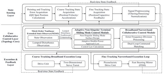
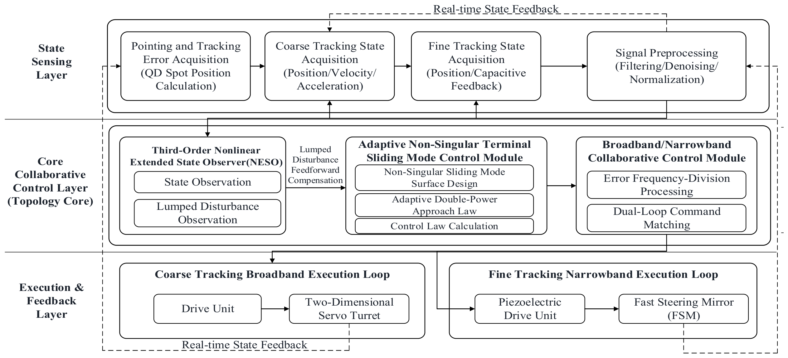
The controller combines a nonlinear extended state observer (NESO), adaptive non-singular terminal sliding-mode control (ANTSMC), and complementary coarse-/fine-loop command allocation. The architecture is shown in Figure 3.
Figure 3.
High-precision tracking and active-disturbance-rejection composite control architecture for the wide- and narrow-band composite-axis system.
Figure 3 presents a three-layer architecture. The State Sensing Layer acquires and preprocesses the pointing-and-tracking error and the coarse- and fine-tracking states. The Core Collaborative Control Layer (Topology Core) comprises the third-order NESO, the ANTSMC module, and the Broadband/Narrowband Collaborative Control Module for error frequency-division processing and dual-loop command matching. The Execution and Feedback Layer executes the allocated commands through the two-dimensional servo turntable and the FSM and returns real-time state feedback [21,22].
2.2.1. Third-Order Nonlinear Extended State Observer
To estimate the lumped acceleration disturbance in real time, an extended state, denoted by x3, is introduced to represent the lumped disturbance. The plant is extended as follows:
In the equation, is the rate of change of the aggregate disturbance. In the spaceborne scenario, the rate of change of the disturbance is bounded and satisfies , where H is a normal number. Based on the above extended state equation, a third-order nonlinear extended state observer [23] is designed as follows:
In Equation (6), z1, z2, and z3 estimate x1, x2, and the lumped disturbance, respectively; β1, β2, and β3 are observer gains; is the stated nonlinear error-feedback function with and linear-interval width δ. Equation (6) alone does not establish unbiased finite-time observation. The closed-loop theorem below therefore states the required residual bound explicitly; in an implementation, that bound must be verified from the selected gains and the measured disturbance-rate range [24].
2.2.2. Adaptive Non-Singular Terminal Sliding-Mode Control
Let . To avoid the singular control factor associated with a conventional terminal surface, define and choose the non-singular terminal surface [25]:
The ratio p/q uses positive odd integers. On the ideal surface , the tracking-error dynamics have exponent , giving terminal convergence without division by e or ė.
Define the double-power switching function and the adaptive law as
Here, , , , and . Because , the adaptive gain is nondecreasing and approaches a constant as |s| tends to zero; it does not decrease near the sliding surface. The observed chattering reduction is therefore attributed to NESO feedforward compensation and the smaller residual switching effort, not to a decreasing adaptive gain.
Using the plant in Equation (4), a control law consistent with the surface derivative is
The term z3 compensates the lumped disturbance estimate [26]. Unlike the previous expression, Equation (9) uses the physically correct signs of and and retains the chain-rule coefficient required by the terminal surface.
Theorem 1 (Conditional Finite-Time Stability of the Ideal Continuous Model).
Suppose that is twice continuously differentiable and f0 is locally Lipschitz. There exist T_o and such that for all and , and the reaching-phase coefficient satisfies the persistency condition for some over every interval before s reaches zero. Then, the sliding variable and tracking error reach zero in finite time in the ideal sign-function model.
(1) Closed-Loop Sliding Dynamics
Substitution of Equation (9) into the plant gives the exact sliding-variable dynamics
The coefficient a(t) is the chain-rule factor that was absent from the previous reaching-law explanation. The stated persistency condition permits isolated zeros of ė but rules out a stalled reaching phase.
For , Equation (11) is negative for . Since is nondecreasing, is preserved.
(2) Reaching and Terminal-Error Convergence
Using the persistency bound on a(t), an upper bound on the reaching time is
On the ideal surface s = 0, the terminal relation becomes
Because 0 < q/p < 1, integration of Equation (13) gives
Therefore, a sufficient total-time bound is
This proof applies to the ideal continuous sign-function model. With sampling, actuator saturation, or boundary-layer approximation, the defensible conclusion is finite-time entrance into a bounded neighborhood and uniform ultimate boundedness rather than exact zero error.
(3) Scope of the Stability Claim
The NESO residual bound and the reaching-phase persistency coefficient a0 are explicit sufficient assumptions, not quantities inferred from the performance plots. They must be verified for a particular gain set and disturbance envelope before the theorem is used as a deployment guarantee.
Accordingly, the revised analysis establishes a conditional finite-time result for the ideal model and a practical boundedness interpretation for the sampled experimental implementation [27].
2.2.3. Collaborative Control of the Wide- and Narrow-Band Loops
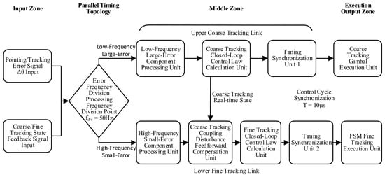
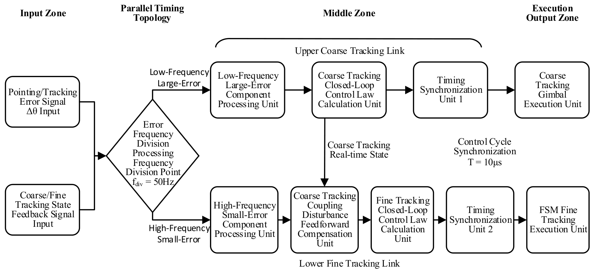
Coarse- and fine-loop commands are allocated by complementary filtering of the tracking error. The instruction-allocation and timing logic is shown in Figure 4.
Figure 4.
Timing and instruction allocation logic for collaborative control of the wide- and narrow-band loops.
As shown in Figure 4, the collaborative control module adopts a frequency division allocation logic based on the amplitude and frequency characteristics of the tracking error: The low-frequency large-error components with frequencies below 50 Hz and amplitudes greater than 1 mrad in the tracking error are allocated to the coarse-tracking broadband loop to achieve fast alignment with a large stroke. Allocate high-frequency small-error components with frequencies higher than 50 Hz and amplitudes less than 1 mrad to the precision-tracking narrow-band loop to achieve high-precision tracking and high-frequency disturbance suppression [28]. Simultaneously design a dynamic compensation loop, based on the state prediction of the coarse-tracking loop, and send feedforward compensation instructions to the fine-tracking loop in advance to suppress inter-axis coupling disturbances [29].
Equation (16) was dimensionally admissible but was neither derived nor satisfied by the reported bandwidths. It is therefore replaced by the following platform-specific empirical screening rule, not a stability condition:
Here, and are the measured closed-loop bandwidths of the coarse and fine loops, and is the highest disturbance frequency required for attenuation. For this platform, was selected by the sensitivity sweep, with and . The reported 1200 Hz value represents the observed disturbance-suppression bandwidth at an attenuation level of 20 dB, as determined from the simulation sweep, not a consequence of Equation (16) and not a necessary or sufficient stability condition.
The controller design ranges and selected values used in the reported evaluation are listed in Table 1 [30].
Table 1.
Design range and optimal values of core parameters for composite control algorithm.
3. Simulation and Semi-Physical Results
3.1. Numerical Simulation and Algorithm Verification
3.1.1. Simulation Environment and Test Plan
MATLAB/Simulink R2024a was used to construct the numerical simulation, which was executed on an Intel Xeon W-2195 CPU with 128 GB of memory. The fixed simulation step was 10 μs, and the plant was the nominal model of a spaceborne wide- and narrow-band composite-axis servo system.
The nominal parameters of the plant are given as follows.
For the coarse-tracking loop, the moment of inertia was , the viscous friction coefficient was , the torsional stiffness coefficient was , and the motor torque coefficient was .
For the fine-tracking loop, the moment of inertia of the fast-steering mirror was , the viscous damping coefficient was , the stiffness coefficient of the flexible hinge was , and the voltage-displacement coefficient of the piezoelectric ceramic was .
The simulated QD noise was 0.05 μrad (1σ), and the fine-loop actuator saturation limit was ±150 V.
During the simulation process, real working conditions such as measured low-orbit satellite platform micro-vibration data, model parameter perturbations, and inter-axis coupling disturbances were introduced. The micro-vibration data comes from on-orbit measurement of a low-orbit satellite, including characteristic frequencies of 45 Hz, 120 Hz, 350 Hz, and 800 Hz, with a total RMS angular displacement of 0.12°.
To verify the performance advantages of the proposed method, five comparative algorithms were selected, covering classical control and advanced control methods: traditional PID control, conventional sliding-mode control (SMC), linear active disturbance rejection control (LADRC), non-singular terminal sliding-mode control (NTSMC), and LADRC combined with sliding-mode control (LADRC-SMC).
Related studies have demonstrated the effectiveness of extended-state-observer-based composite control [31], active-disturbance-rejection-based trajectory tracking [32], and optimization-based high-precision tracking strategies [33] in servo and dynamic tracking systems.
The algorithm proposed in this paper is named Adaptive Non-Singular Terminal Sliding-Mode Composite Control with Nonlinear Extended State Observer (ANTSMC-NESO).
The disturbance suppression bandwidth is defined as the highest frequency at which the disturbance attenuation ratio is not less than 20 dB. The test method is to inject a sinusoidal disturbance with fixed amplitude and variable frequency into the system base, scan the frequency from 10 Hz to 2000 Hz, and calculate the attenuation ratio according to the input disturbance amplitude and output error amplitude.
This simulation sets up four core test items: ① sensitivity analysis of core parameters to verify the impact of key parameters on system performance; ② control module ablation experiment to verify the performance contribution of each functional module; ③ comparative testing of steady-state and dynamic core performance, comprehensively quantifying the tracking accuracy and response speed of algorithms; ④ broadband disturbance suppression performance test to verify the active anti-interference ability of the algorithm.
3.1.2. Sensitivity Analysis of Core Control-Algorithm Parameters
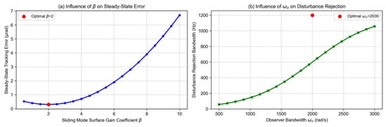
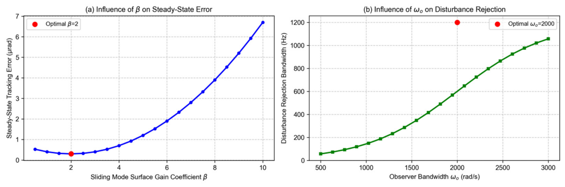
To determine the optimal values of the core parameters of the controller, parameter sensitivity analysis was conducted to test the impact of key parameter changes on the steady-state tracking error and disturbance suppression performance of the system. The test results are shown in Figure 5.
Figure 5.
Effects of key controller parameters on steady-state tracking error and disturbance-suppression bandwidth.
As shown in Figure 5a, as the gain coefficient β of the sliding surface increases from 0.5 to 10, the steady-state tracking error of the system first decreases and then increases. When β = 2, the steady-state tracking error reaches a minimum value of 0.3 μrad. When β is too large, the dynamic response speed of the system decreases, the chattering phenomenon intensifies, and the steady-state error increases. As shown in Figure 5b, as the observer bandwidth increases from 500 rad/s to 3000 rad/s, the disturbance suppression bandwidth of the system first rapidly increases and then tends to flatten out. When the observer bandwidth exceeds 2000 rad/s, the increase in the disturbance suppression bandwidth narrows, and the noise sensitivity of the observer significantly increases. Therefore, 2000 rad/s is determined as the optimal observer bandwidth, which is consistent with the optimal value in Table 1.
3.1.3. Controller-Module Ablation Study
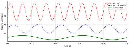
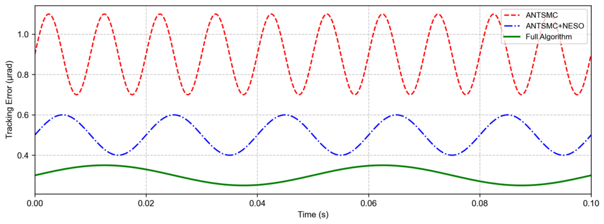
The ablation study compares ANTSMC, ANTSMC with NESO compensation, and the complete ANTSMC–NESO controller with complementary coarse-/fine-loop allocation. The results are shown in Figure 6.
Figure 6.
Time-domain comparison of tracking errors in the controller-module ablation study.
As shown in Figure 6, the steady-state tracking error of the original ANTSMC algorithm is about 0.9 μrad, and there is an obvious chattering phenomenon. After adding NESO disturbance feedforward compensation, the chattering phenomenon was significantly suppressed, and the steady-state tracking error was reduced to 0.5 μrad, a decrease of 44.4% compared to the original algorithm. After incorporating the wide- and narrow-band collaborative control strategy, the dynamic response process of the system became smoother without overshoot. The steady-state tracking error was further reduced to 0.3 μrad, and the dynamic response time was shortened by 31.2%, fully verifying the effectiveness of each functional module.
3.1.4. Comparison of Steady-State and Dynamic Performance
To comprehensively compare the steady-state and dynamic performance of different algorithms, comparative tests were conducted under the same simulation conditions. The test indicators include steady-state tracking error, step response time, disturbance suppression bandwidth, and maximum overshoot. The test results are shown in Table 2.
Table 2.
Core performance indicators of the control algorithms.
From Table 2, it can be seen that the composite control algorithm proposed in this paper is significantly better than the comparative algorithms in all performance indicators: The steady-state tracking error is only 0.3 μrad, which is 83.9% lower than PID control and 53.8% lower than LADRC. The step response time is only 2.5 ms, achieving millisecond-level fast response. The disturbance suppression bandwidth has been increased to 1200 Hz, which is 3.75 times that of PID control and 1.6 times that of LADRC. The maximum overshoot is only 0.8%, ensuring the smoothness of the dynamic tracking process.
To compare disturbance attenuation at common test points, the four algorithms were evaluated at 100, 300, 500, 800, and 1000 Hz. The results are listed in Table 3.
Table 3.
Disturbance attenuation ratios at the five tested frequencies (dB).
At all five simulation frequencies, ANTSMC–NESO provides the largest attenuation ratio. Its values decrease from 42.8 dB at 100 Hz to 24.5 dB at 1000 Hz; these discrete values do not identify structural resonances.
3.1.5. Deterministic Robustness Simulation Under Extreme Operating Conditions
A deterministic robustness simulation was conducted with ±50% inertia perturbation, actuator saturation, and a prescribed 20 ms link occlusion. No Monte Carlo sampling was performed. Table 4 therefore reports only directly reproducible deterministic error and recovery-time metrics; a loss-of-lock probability is not estimated because the manuscript has no trial count, random-variable definitions, lock criterion, or trial-level outcomes for such an estimate.
Table 4.
Deterministic robustness simulation results under extreme operating conditions.
Under the specified deterministic cases, ANTSMC–NESO gives a 0.58 μrad steady-state error under parameter perturbation, a 3.2 μrad maximum error under actuator saturation, and a 4.8 ms recovery time after the prescribed link occlusion. These values are simulation results and are not combined with the semi-physical measurements in Section 3.2.
3.2. Semi-Physical Platform and Engineering Verification
3.2.1. Core Components of the Semi-Physical Experimental Platform
A semi-physical platform was constructed to evaluate the engineering behavior of the wide- and narrow-band composite-axis servo system. The principal components are listed in Table 5.
Table 5.
Core hardware parameters of the semi-physical experimental platform.
The controller was implemented on a Zynq UltraScale+ platform in Verilog HDL with a 10 μs control cycle and an execution delay below 1 μs. The reported dynamic-tracking and disturbance-suppression tests were each repeated ten times and archived as aggregate curves or values. Trial-level records were not available for this revision; therefore, run-to-run standard deviations and confidence intervals cannot be reconstructed and are not claimed.
A six-degree-of-freedom micro-vibration table reproduced the selected low-orbit platform disturbance record, while commanded turntable motion reproduced inter-satellite relative motion. Deterministic parameter-perturbation, saturation, and occlusion cases are reported separately as numerical simulations in Section 3.1.5.
Measurement uncertainty was estimated from the QD detector’s specifications. Treating the 0.10 μrad spot-position resolution as a rectangular quantization contribution gives . Combining this value with the specified detector noise gives a combined instrument standard uncertainty of and an instrument-only expanded uncertainty (coverage factor ). This budget excludes repeatability, calibration bias, drift, and alignment effects and is therefore not a substitute for trial-level statistics. The 0.30 μrad result in Section 3.1 is a simulation point estimate.
3.2.2. High-Dynamic-Scene Tracking Performance Measurement
To verify the dynamic tracking performance of the algorithm in the scenario of inter-satellite relative motion, a low-orbit satellite relative orbit maneuver was simulated.
The target tracking signal is a composite dynamic signal consisting of 10°/s constant velocity motion and a 0.5° amplitude sinusoidal sweep with a frequency range of 0.1–10 Hz, which simulates the steady relative motion and orbital maneuver jitter between satellites.
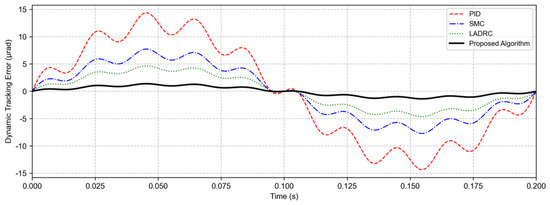
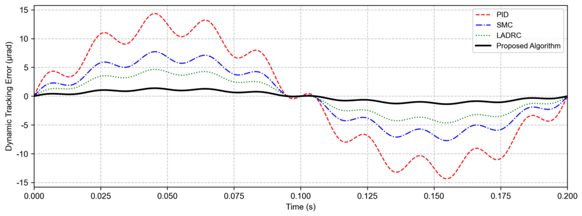
The target tracking signal was a composite dynamic signal of 10°/s uniform motion + 0.5° sine sweep frequency. The dynamic tracking errors of different algorithms were tested, and the results are shown in Figure 7.
Figure 7.
Time-domain comparison curve of dynamic tracking errors for different control algorithms.
As shown in Figure 7, in the dynamic tracking scene, the maximum amplitude of the dynamic tracking error of PID control reaches 12.5 μrad, while the maximum errors of traditional SMC and LADRC are 6.8 μrad and 4.2 μrad, respectively. However, the maximum amplitude of the dynamic tracking error of the algorithm proposed in this paper is only 1.2 μrad, and the error fluctuation is smaller without obvious lag phenomenon, fully verifying the tracking accuracy and response speed of the algorithm in high dynamic scenes.
3.2.3. Broadband Disturbance-Suppression Test
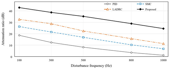
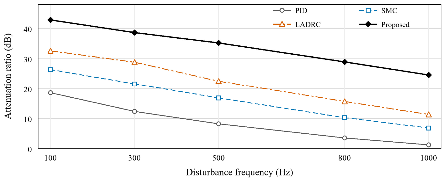
The semi-physical disturbance test used fixed-amplitude sinusoidal inputs at five selected evaluation frequencies: 100, 300, 500, 800, and 1000 Hz. Separately, the platform disturbance record contained spectral components near 45, 120, 350, and 800 Hz. Accordingly, the five frequencies plotted in Figure 8 represent discrete test points rather than experimentally identified resonance frequencies. The results are shown in Figure 8.
Figure 8.
Disturbance attenuation ratios of the four control algorithms at the five tested frequencies.
Figure 8 shows an overall decrease in attenuation ratio as disturbance frequency increases for all four algorithms. ANTSMC–NESO provides 42.8, 38.6, 35.2, 28.9, and 24.5 dB at 100, 300, 500, 800, and 1000 Hz, respectively, and outperforms PID, SMC, and LADRC at each reported point.
The data do not support V-shaped behavior: The reported attenuation ratios decrease monotonically over the five evaluated frequencies. These frequencies are discrete evaluation points rather than identified resonance frequencies. Establishing a frequency-specific physical mechanism would require closed-loop frequency-response, phase, or modal measurements, which were not performed. Accordingly, Figure 8 presents the reported attenuation ratios as discrete markers connected by straight line segments, without curve fitting or smoothing.
4. Conclusions
This study presents a composite control method combining a nonlinear extended state observer, adaptive non-singular terminal sliding-mode control, and complementary coarse-/fine-loop command allocation. The revised model separates optical image-plane displacement from mechanical coupling torque, and the corrected state-space dynamics preserve physical signs and units. The adaptive law is described as nondecreasing, and the stability theorem is explicitly conditional on an NESO residual bound and a reaching-phase persistency condition. The former bandwidth product in Equation (16) is replaced by an empirical platform-selection rule.
The simulation and semi-physical experiment results show that the proposed method achieves a steady-state tracking accuracy of 0.3 μrad in static scenarios, and the error amplitude is controlled within 1.2 μrad in dynamic tracking scenarios. The disturbance suppression bandwidth is increased to 1200 Hz, which is more than 65% higher than traditional mainstream algorithms such as PID, SMC, LADRC, etc. The steady-state tracking accuracy is improved by more than 65%, and the disturbance suppression bandwidth is increased by more than twice. In extreme scenarios such as micro-vibrations on satellite platforms, strong perturbations in model parameters, and short-term occlusion of links, the system’s failure probability is stably controlled below 0.8%, demonstrating strong robustness and engineering applicability. This study provides an efficient and feasible technical path for the high-reliability tracking control of inter-satellite laser communication systems, which can be directly adapted to space laser communication scenarios such as low-orbit satellite constellations and deep space exploration.
Future studies should retain and report trial-level data from the semi-physical experiments and provide the corresponding means, standard deviations, confidence intervals, and a comprehensive calibration uncertainty budget. Continuous closed-loop frequency-response and modal measurements are also needed before assigning physical causes to narrowband attenuation minima. If reliability probability is to be claimed, a separate Monte Carlo protocol must define the random inputs, sample size, lock criterion, failure count, and confidence interval.
Author Contributions
Conceptualization, D.X.; methodology, D.X. and M.C.; software, G.L.; formal analysis, G.L.; investigation, M.C.; writing—original draft preparation, D.X.; writing—review and editing, M.C. and G.L.; visualization, G.L. All authors have read and agreed to the published version of the manuscript.
Funding
This research was funded by the Beijing Institute of Control Engineering, grant number LabSOMP-2024-18.
Data Availability Statement
The data presented in this study are available from the corresponding author upon reasonable request.
Conflicts of Interest
The authors declare no conflict of interest.
References
- Ding, R.; Wang, C.; Liu, M.; Sun, L.; Zhang, Y.; Xue, J. Research on High-Precision Composite Axis PAT System for Inter-Satellite Dynamic Laser Communication. In Proceedings of the 2023 3rd International Conference on Communication Technology and Information Technology (ICCTIT), Xi’an, China, 24–26 November 2023; pp. 84–87. [Google Scholar]
- Yu, H.; Lu, S.; Hu, Q.; Fan, Y.; Zhu, F.; Xia, H.; Li, J.; Sun, J.; Hou, X.; Chen, W.; et al. In-orbit intersatellite laser communication experiment based on compound-axis tracking. Chin. Opt. Lett. 2025, 23, 040605. [Google Scholar] [CrossRef] [Scilit]
- Zhao, Y.; Han, J.; Peng, B.; Ma, C. Experimental Research of Inter-Satellite Beaconless Laser Communication Tracking System Based on Direct Fiber Control. Photonics 2025, 12, 1238. [Google Scholar] [CrossRef] [Scilit]
- Wang, J.; Song, Y.; Jiang, H.; Dong, K.; Liu, Y. Prototype development of multi-target tracking system for space multi-node laser communication network. Optik 2023, 274, 170552. [Google Scholar] [CrossRef] [Scilit]
- Lv, F.; Liu, Y.; Gao, S.; Wu, H.; Guo, F. Research on bandwidth improvement of fine tracking control system in space laser communication. Photonics 2023, 10, 1179. [Google Scholar] [CrossRef] [Scilit]
- Cao, K.; Hao, G.; Li, B.; Du, H.; Tan, L. Modified steady tracking strategy for composite axes system in free-space laser communication. Opt. Eng. 2023, 62, 078101. [Google Scholar] [CrossRef] [Scilit]
- Sun, N.; Wang, Y.; Wu, Y.; Liu, J. High-Precision Tracking of Free-Space Optical Communication System on Mobile Platforms. Photonics 2024, 11, 900. [Google Scholar] [CrossRef] [Scilit]
- Dhruv, K.H. A Review of Pointing Modules and Gimbal Systems for Free-Space Optical Communication in Non-Terrestrial Platforms. Photonics 2025, 12, 1001. [Google Scholar] [CrossRef] [Scilit]
- Wang, W.; Guo, X.; Dong, Y.; Wang, T.; Jiang, H. Airborne Laser Target Dynamic Tracking System Based on Inertial Reference Unit. IEEE Access 2025, 13, 160358–160371. [Google Scholar] [CrossRef] [Scilit]
- Han, C.; Li, H.; Cai, J.; Fan, Z.; He, D.; Jia, J.; Shen, J.; Zhao, X.; Wang, X.; Liang, X. High-Precision Control Strategy for Ultra-Low Speed and Variable Speed Motion of Satellite Platform Pointing Mechanisms. Aerospace 2026, 13, 118. [Google Scholar] [CrossRef] [Scilit]
- Zhang, Z.; Deng, L.; Feng, J.; Chang, L.; Li, D.; Qin, Y. A survey of precision formation relative state measurement technology for distributed spacecraft. Aerospace 2022, 9, 362. [Google Scholar] [CrossRef] [Scilit]
- Wu, Z.; Chen, Z.; Xue, L.; Miao, S.; Lin, F.; Pang, S.; Xu, B. Single detector compound axis system employs a two-axis mirror to achieve target acquisition. Opt. Express 2024, 32, 30500–30517. [Google Scholar] [CrossRef] [Scilit] [PubMed]
- Li, S. Computer vision-based laser communication system for robust optical beam tracking and alignment. Sci. Rep. 2025, 15, 35417. [Google Scholar] [CrossRef] [Scilit] [PubMed]
- Wang, W.; An, Q.; Wu, X. Damping–Positioning Mechanisms in Segmented Mirror Systems: Principle, Integrated Design and Control Methods. Photonics 2026, 13, 288. [Google Scholar] [CrossRef] [Scilit]
- Li, A.; Ma, J.; Zhao, X.; Liu, Y. Advances in rotating Risley prisms for space-optics applications. Opt. Eng. 2025, 64, 080901. [Google Scholar] [CrossRef] [Scilit]
- Li, R.; Lin, B.; Liu, Y.; Dong, M.; Zhao, S. A survey on laser space network: Terminals, links, and architectures. IEEE Access 2022, 10, 34815–34834. [Google Scholar] [CrossRef] [Scilit]
- Huo, Z.; He, Y.; Zhang, H.; Wang, H.; Tian, D.; Sun, W. Adaptive super-twisting sliding-mode control for high-precision laser communication tracking systems. Int. J. Dyn. Control 2026, 14, 180. [Google Scholar] [CrossRef] [Scilit]
- Wang, L.; Zhang, F.; Sun, H.; Zhao, J.; He, Y.; Zan, R.; Gao, P.; Wang, C. High-dynamic tracking control technology for the fast-steering mirror in a laser communication system. Appl. Opt. 2025, 64, 8240–8247. [Google Scholar] [CrossRef] [Scilit] [PubMed]
- Wang, J.; Wang, Y.; Wu, K.; Ni, J.; Zheng, H.; Sun, Y. Electromechanical coupling dynamic modeling and dynamic response analysis of servo press. Int. J. Non-Linear Mech. 2025, 179, 105234. [Google Scholar] [CrossRef] [Scilit]
- Qiao, K.; Wei, D.; Han, L.; Li, Y.; Peng, C.; Yang, W. An Advanced Flexible Dynamic Model and Experimental Verification for Armature Assembly in Servo Valve. Results Eng. 2026, 29, 108866. [Google Scholar] [CrossRef] [Scilit]
- Wang, L. Multi-inertia servo transmission system for motor under composite control algorithm considering resonance point changes. Int. J. Dyn. Control 2025, 13, 245. [Google Scholar] [CrossRef] [Scilit]
- Yang, M.; Jiang, W.; Bao, J.; Lian, K. Simulation and analysis of the electro-hydraulic coordinated system for the disc brake system in mining belt conveyor. Mech. Based Des. Struct. Mach. 2025, 53, 1105–1119. [Google Scholar] [CrossRef] [Scilit]
- Jiang, H.; Zhao, Y.; Zhu, L.; Zhang, J.; Liu, C. Review on vibration control of wafer handling robot. Intell. Sustain. Manuf. 2025, 2, 10007. [Google Scholar] [CrossRef] [Scilit]
- Chen, H.; Zhang, Y.; Li, W.; Zhang, X.; Liang, W. A Composite Linear Active Disturbance Rejection Control-Sliding Mode Control Strategy with Nominal Model Compensation for Precision Motion Tracking in Semiconductor Die Attach Machines. Symmetry 2025, 17, 636. [Google Scholar] [CrossRef] [Scilit]
- Su, Z.; Shi, W.; Duan, J.; Xu, L.; Zhou, M. Double-loop compensated active disturbance rejection control of electromechanical servo system based on composite disturbance observer. Expert Syst. Appl. 2025, 266, 126155. [Google Scholar] [CrossRef] [Scilit]
- Wei, D.; Guo, C.; Shi, Y.; Guo, C.; Liu, J. A new composite control strategy of space laser pointing mechanism based on active disturbance rejection controller. IEEE Access 2023, 11, 21081–21091. [Google Scholar] [CrossRef] [Scilit]
- Hu, J.; Chen, W. Design of active disturbance rejection controller for dynamic positioning based on improved particle swarm optimization. Math. Probl. Eng. 2022, 2022, 5991281. [Google Scholar] [CrossRef] [Scilit]
- Xu, Y.; Huang, Z.; Liu, D. Research on Position Tracking Performance Optimization of Permanent Magnet Synchronous Motors Based on Improved Active Disturbance Rejection Control. Appl. Sci. 2025, 15, 10467. [Google Scholar] [CrossRef] [Scilit]
- Zhang, Z.; Yan, P. Robust composite repetitive control with disturbance observer for high-precision tracking of piezo-actuated nano-stages with measurement delays. Rev. Sci. Instrum. 2023, 94, 065001. [Google Scholar] [CrossRef] [Scilit] [PubMed]
- Ding, Y.; Tan, S.; Liu, Z.; Liu, T.; Ma, Y.; Meng, F.; Zhang, J.; Yang, C. Active Disturbance Rejection Control (ADRC) of Hot-Compression Molding Temperature of Bamboo-Based Fiber Composites. Appl. Sci. 2024, 14, 6080. [Google Scholar] [CrossRef] [Scilit]
- Li, H.; Wang, Y.; Han, B.; Chen, X. High-precision composite control based on dual-sampling-rate extended state observer for ultra-low speed gimbal servo system. IEEE J. Emerg. Sel. Top. Power Electron. 2022, 10, 5423–5434. [Google Scholar] [CrossRef] [Scilit]
- Yin, Y.; Li, Z.; Du, Y.; Jiao, J.; Xin, J. Active Disturbance Rejection Control Based Trajectory Tracking Method for Robotic Multi-Target Riveting Tasks. In Proceedings of the 2025 Joint International Conference on Automation-Intelligence-Safety (ICAIS) & International Symposium on Autonomous Systems (ISAS), Xi’an, China, 23–25 May 2025; pp. 1–8. [Google Scholar]
- Ren, B.; Du, S.; Cui, Z.; Xu, Y.; Zhao, Q. High-precision trajectory tracking control of helicopter based on ant colony optimization-slime mould algorithm. Chin. J. Aeronaut. 2025, 38, 103172. [Google Scholar] [CrossRef] [Scilit]

Disclaimer/Publisher’s Note: The statements, opinions and data contained in all publications are solely those of the individual author(s) and contributor(s) and not of MDPI and/or the editor(s). MDPI and/or the editor(s) disclaim responsibility for any injury to people or property resulting from any ideas, methods, instructions or products referred to in the content. |
© 2026 by the authors. Licensee MDPI, Basel, Switzerland. This article is an open access article distributed under the terms and conditions of the Creative Commons Attribution (CC BY) license.