


Abstract
This paper presents the design and numerical assessment of a compact short-wave infrared (SWIR) optical payload for a CubeSat nanosatellite platform. The proposed payload is intended to provide sequential imaging in selected SWIR bands using a revolver filter wheel while accommodating a long-focal-length optical system within a limited 3U volume. The optical layout is based on a modified Maksutov configuration with an effective focal length of approximately 550 mm and an aperture of 84 mm. The system is designed to achieve a ground sampling distance (GSD) of ≤15 m at an orbital altitude of 500–550 km. For sequential imaging in different regions of the SWIR range, filters with central wavelengths of 1.24, 1.6, 1.9, and 2.1 μm are used together with an additional broadband window. The optical performance was evaluated using spot diagrams and modulation transfer function (MTF) analysis for the selected spectral bands. A preliminary thermo-optical sensitivity assessment was also performed over the temperature range from −20 °C to +40 °C by considering temperature-induced changes in axial distances between optical elements and surface curvatures caused by material expansion. The results indicate that the MTF at the detector Nyquist frequency of 33 lp/mm remains above the selected threshold of 0.1 for the considered spectral bands and uniform temperature states. The proposed configuration demonstrates the feasibility of implementing a compact long-focal-length SWIR payload with filter-wheel-based band selection for CubeSat missions, while maintaining the required calculated image quality within the considered design-stage assumptions.
1. Introduction
The use of the short-wave infrared (SWIR) range in Earth observation tasks is necessary for detailed mapping of soil moisture and analysis of the mineral composition of the surface [1,2]. Spectral bands in the regions of 1.24 µm and 2.1 µm enable mineral identification, while the 1.6 µm and 1.9 µm bands are used to account for the effects of atmospheric water vapor absorption [3,4]. The effectiveness of image processing in these spectral windows is determined not only by band selection. The ability of the instrument to preserve the calculated optical characteristics under changing thermal conditions in orbit is also essential [5,6].
The CubeSat standard, which sets the mass of 1U at up to 1.33 kg, enables the deployment of cost-effective constellations of small satellites to achieve high temporal resolution of data [7,8]. However, compact platforms impose strict constraints on payload volume, mass, power consumption, and thermal conditions [9,10]. The placement of long-focal-length SWIR optics within the volume of a nanosatellite remains a particularly challenging task. Such a system must include an optical path, a filter wheel, a detector, and mounting elements. At the same time, the relative alignment of the optical elements must be preserved under mechanical and thermal influences.
The main engineering contradiction lies in the need to combine the compactness of the optical system with a sufficiently large focal length and aperture to achieve the required GSD. Compact spectrometers and systems based on linear variable filters make it possible to reduce the payload dimensions, but they do not always provide the required spatial resolution [11,12,13]. To obtain a GSD ≤ 15 m, an optical layout with a sufficient aperture is required. With a pixel size of 15 µm and an orbital altitude of 550 km, a focal length of approximately 550 mm is required to achieve a resolution no worse than 15 m. Implementing such a system in the 3U format is difficult without special optomechanical optimization [14,15].
For long-focal-length SWIR optics, not only detector temperature fluctuations but also thermoelastic displacements of the optical elements are critical. Therefore, the structure must preserve the relative position of the mirrors and lenses under temperature changes, and the materials of the optical and mechanical elements must be selected with account for launch vibration loads [16] and compatibility of thermal expansion coefficients [17].
The mechanical stability of the payload was evaluated at the design stage using finite-element analysis. Experimental verification by vibration and thermal-vacuum testing is planned after assembly and alignment of the optical payload.
The objective of this work is to design and numerically assess a compact long-focal-length SWIR optical payload for a CubeSat platform. The proposed payload is based on a modified Maksutov optical configuration and uses a revolver filter wheel to enable sequential imaging in selected SWIR bands. For the preliminary configuration, filters with central wavelengths of 1.24, 1.6, 1.9, and 2.1 μm were selected as representative regions of the SWIR range used in Earth observation tasks. The study aims to verify the feasibility of placing a long-focal-length optical system within the limited 3U payload volume while maintaining the required image quality and compatibility with the expected mechanical and thermal operating conditions.
The scientific and technical novelty of this work lies in the integrated implementation of a compact SWIR optical payload for a nanosatellite platform. In the proposed solution, a long-focal-length optical system is placed within the limited volume of a CubeSat and combines high spatial resolution, an optomechanical structure aimed at reducing thermoelastic sensitivity, vacuum-compatible design considerations, and the capability to select the spectral band using a revolver filter wheel. The instrument forms an image in one selected band during one imaging cycle; however, the filter switching mechanism makes it possible to sequentially acquire data in four SWIR bands.
This paper presents a modified Maksutov optical layout with an aperture of 84 mm. The optical system uses lenses made of JGS3 fused silica and mirror elements on JGS1 substrates. The choice of mount materials and the use of Invar 36 are aimed at reducing thermoelastic displacements and preserving the optical geometry, which contributes to maintaining MTF > 0.1 over the range from −20 °C to +40 °C. The calculated threshold MTF > 0.1 was taken from the authors’ experience in previous projects. The filter wheel design and the results of the analysis of the influence of temperature on image quality are also described.
At the current stage, the optical layout and mechanical structure have been designed, the image quality has been numerically assessed, preliminary mechanical analysis has been performed, interfaces with the spacecraft platform have been developed, and the filter switching system has been designed. A preliminary mechanical mock-up has also been manufactured, on which the assembly sequence and access to fastening elements during assembly and alignment were verified. The system is currently being assembled, and software for controlling the filter switching mechanism is being developed.
2. Materials and Methods
2.1. Optical Configuration, Materials, and Payload Design Parameters
The optical elements are made of fused silica, chosen for its high transmittance in the near-infrared range. The lens system uses JGS3 glass. Fused silica JGS1 was selected as the substrate material for the mirror elements. This material contains a higher concentration of hydroxyl (OH) groups, which slightly reduces transmission in the 1.4–2.7 μm spectral range; however, this effect does not influence the reflective properties of the mirror. The reflective surface is coated with aluminum, providing high reflectivity in the visible and near-infrared spectral regions. JGS1 also exhibits mechanical and thermal properties similar to those of JGS3, including a low coefficient of thermal expansion and high dimensional stability. In contrast, JGS3 contains a significantly lower concentration of OH groups and offers a wider transmission range, which makes it a more suitable material for anti-reflection coated lens elements operating in the SWIR spectral region.
To complete the optical chain, a revolver-style filter wheel with four spectral bands is placed at the focal plane. These filters, also based on fused silica substrates, are selected to match the atmospheric transparency windows and remote sensing requirements. Bands at 1.24 and 2.1 μm are used for surface mineral composition and moisture analysis [4], while 1.6 and 1.9 μm bands account for atmospheric water vapor effects [18]. The filter wheel also includes a fifth slot, which will be occupied by an uncoated window for broadband image acquisition.
The spectral configuration of the filter wheel and the purpose of each band are presented in Table 1.
Table 1.
Spectral configuration of the filter wheel.
The fifth slot of the filter wheel is intended for broadband image acquisition through an uncoated window. This mode provides a higher signal level compared with narrowband bands and can be used for general scene imaging, optical alignment verification, payload functional checks, and comparison with spectrally filtered images.
A preliminary tolerance analysis was performed using a Monte Carlo approach with 1000 iterations to evaluate the sensitivity of the optical performance to manufacturing and alignment errors. The analysis included variations in surface radii, inter-element spacing, decentering, and tilt. The results indicate that the selected tolerance assumptions are compatible with the expected manufacturing and assembly capabilities; however, final validation will be performed after assembly and optical alignment.
The detector parameters used in the optical design are summarized in Table 2. The InGaAs detector is placed behind the filter wheel and records images in the selected spectral band. The proposed optical system provides the required GSD while maintaining compact dimensions, making it suitable for small satellite payloads and CubeSat platforms. The selected filters are used in this work primarily to demonstrate the filter-wheel-based band switching concept.
Table 2.
Main requirements and design parameters of the payload.
The optical payload was developed taking into account the constraints of the 3U nanosatellite platform, spatial resolution requirements, spectral range, temperature stability, and mechanical stiffness. The main requirements and design parameters used in the optical and optomechanical analysis are presented in Table 2.
2.2. Optomechanical Structure and Thermo-Optical Modeling
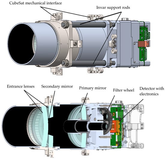
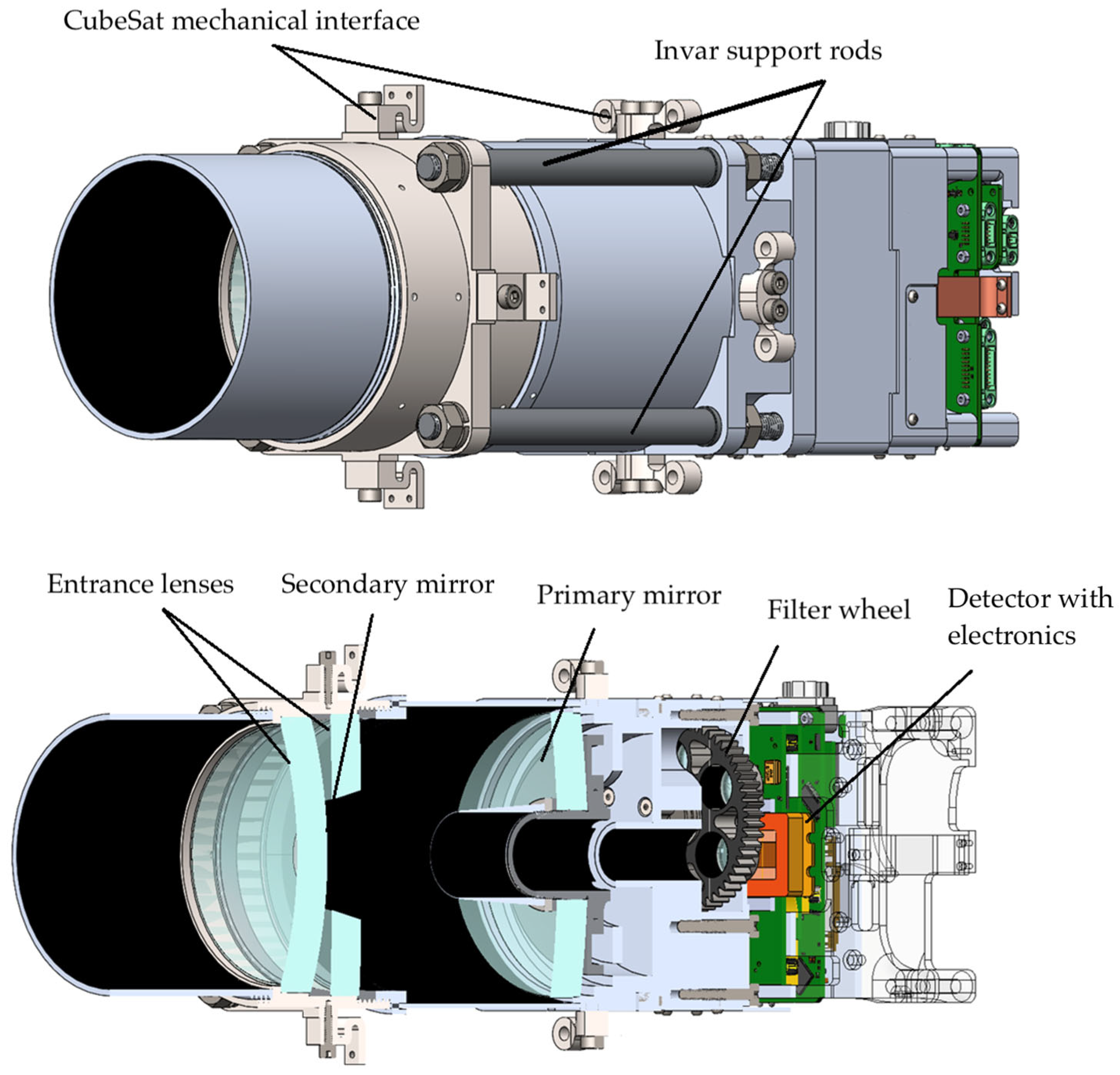
The payload optical system was developed within the constraints of CubeSat and nanosatellite platforms, with an allocated 3U volume of 10 cm × 10 cm × 34 cm and a preliminary instrument mass of 3.7 kg. The mechanical design of the optical instrument was driven by three main requirements. First, the structure must withstand launch loads; therefore, Falcon 9 loads [19] were selected as a reference for quasistatic and dynamic load conditions. Second, the relative alignment of the optical elements must be preserved over the operating temperature range from −20 °C to +40 °C. Third, the first global natural frequency of the optical instrument must exceed 100 Hz to avoid low-frequency sinusoidal loading [20]. The overall configuration and main components of the SWIR optical instrument are shown in Figure 1.
Figure 1.
External and cutaway view of SWIR optical instrument.
To support these design objectives, an iterative optomechanical design process was carried out using finite-element calculations in Ansys Mechanical 2025 and optical performance evaluation in Zemax. The finite-element calculations were used to support preliminary mechanical feasibility assessment and optomechanical design decisions. At this design stage, the structural model was not intended to serve as a final qualification model of the payload. Therefore, a full mesh-convergence study was not performed within the scope of the present manuscript. The mesh density was selected to provide stable estimates of the main design-level quantities, including deformation trends and the first natural frequency of the selected support elements. A detailed mesh-convergence assessment will be performed at the next development stage using the final mechanical model prepared for vibration and thermal-vacuum verification.
The thermo-optical part of the work was performed as a design-stage sensitivity assessment rather than as a fully coupled structural–thermal–optical analysis. The modeling was performed under deep-vacuum conditions, with atmospheric pressure assumed to be zero. The analysis covered the operating temperature range from −20 °C to +40 °C with a step of 10 °C. The model accounted for temperature-induced changes in axial distances between optical elements and changes in surface curvatures caused by thermal expansion of the selected materials, while the refractive indices of the materials were assumed to remain stable. The resulting optical performance was evaluated using MTF and PSF criteria. This approach provides a preliminary estimate of the influence of temperature-induced geometric changes on image quality, while full coupled structural–thermal–optical verification and experimental validation will be addressed in future work after assembly and alignment of the payload. The calculations were based on the coefficients of thermal expansion listed in Table 3.
Table 3.
Material properties.
Tight tolerances on the axial distance between primary and secondary mirrors dictated use of Invar 36 for connecting structure between them in order to keep alignment within the planned operating temperature range. As a common practice among optical payload platforms for CubeSat missions [21], four Invar rods were selected as the main support elements between the primary- and secondary-mirror subassemblies. The rod thickness was selected not only to provide sufficient stiffness, but also to preserve the relative alignment of the optical elements under mechanical and thermal loads. A preliminary feasibility analysis showed that the selected support concept has its first bending mode at approximately 186 Hz. The corresponding preliminary modal-analysis results are shown in Figure 2. This value was used as a preliminary stiffness indicator rather than as a complete verification of launch-load survivability. It is important to note that this analysis included only base plate attachment to the satellite chassis, and the rigidity of the payload may be improved when adding lens barrel mounts.
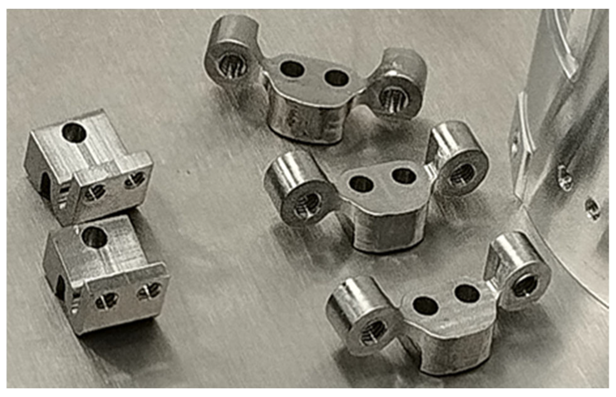
However, the design objective was not only to maximize stiffness, but also to preserve alignment and reduce the transmission of launch-induced loads to sensitive optical components. For this reason, the payload uses short and symmetric load paths, Invar support rods, flexural mounting principles for the primary mirror, and a mechanically constrained filter-wheel assembly. These design choices are intended to balance structural stiffness, vibration robustness, and alignment stability. A detailed vibration-response assessment, including damping assumptions and experimental vibration testing, will be performed at the next stage using the assembled payload. In a CubeSat platform, additional mounting points may be available through lateral interfaces or rail-based installation, which can further increase the overall rigidity of the payload integration. The structure provides interfaces for connection to the CubeSat platform through external titanium fixtures, as shown in Figure 3. These fixtures were modeled using the approach applied in the team’s previous project [22].
Figure 2.
Preliminary modal analysis of the invar rods, rods simulated as 1D beams with RBE2 attachment to platforms, with elements of the payload modeled as point masses attached to the base plate and lens barrel via RBE2.
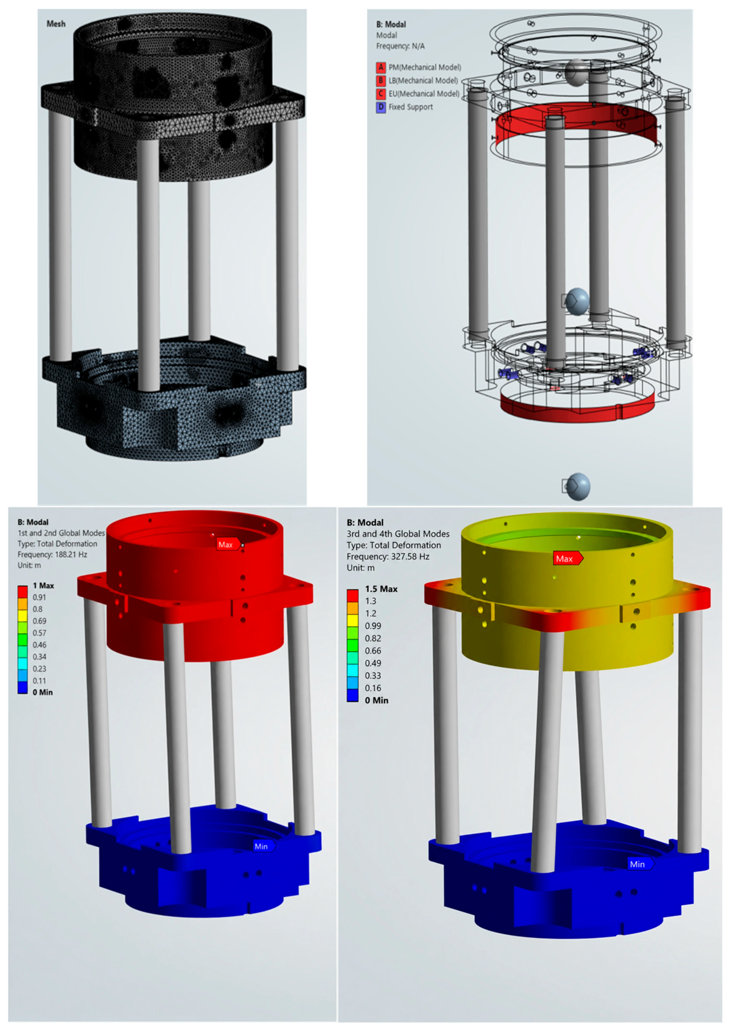
Figure 3.
External titanium fixtures that are used for connection to the CubeSat platform [22].
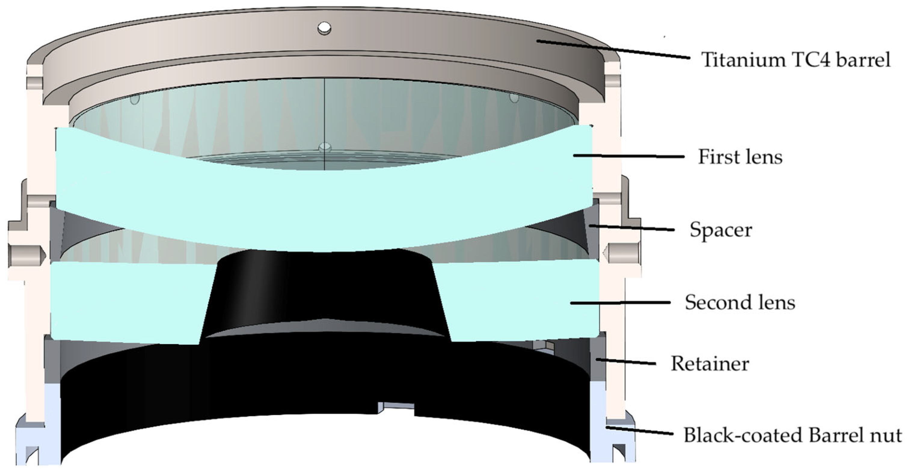
Coupling this design choice with the size of the optical system and dimensional restrictions of the CubeSat bus, a barrel drop-in mounting method was chosen to house the two input lenses [23]. Considering the roughly 6:1 diameter-to-thickness ratios of the lenses, their dimensions and stiffness make the stepped rim-mounting technique appropriate for the assembly of the lens barrel. Without any adjustment, tilts of the elements within a maximum radial clearance of 20 µm will be within the analyzed tolerances, which is achievable with traditional manufacturing methods. A perpendicular bevel will be ground on the concave surface of the first lens to interface with the barrel seat and increase its wedge angle for better transverse preloading. Titanium TC4 alloy was chosen as the barrel material, with a spacer and a retainer made of Invar 36. Stray-light analysis showed that the second lens’s own thickness was enough to limit parasitic light, so its inner rim will be coated in black to act as a baffle. An SWIR-compatible low-reflectance foil, Acktar Metal Velvet™ with low-outgassing adhesive, was selected for the baffle surface. According to the specifications, the material provides broadband absorption over the 0.3–14 μm wavelength range, which fully covers the operating SWIR bands of the payload at 1.24, 1.6, 1.9, and 2.1 μm. The material is specified as an ultra-diffusive matte coating with very low reflectance, making it suitable for stray-light suppression in the considered SWIR optical path. The resulting lens-barrel configuration is shown in Figure 4.
Figure 4.
Section view of the lens barrel design for the Maksutov telescope.
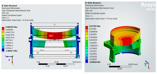
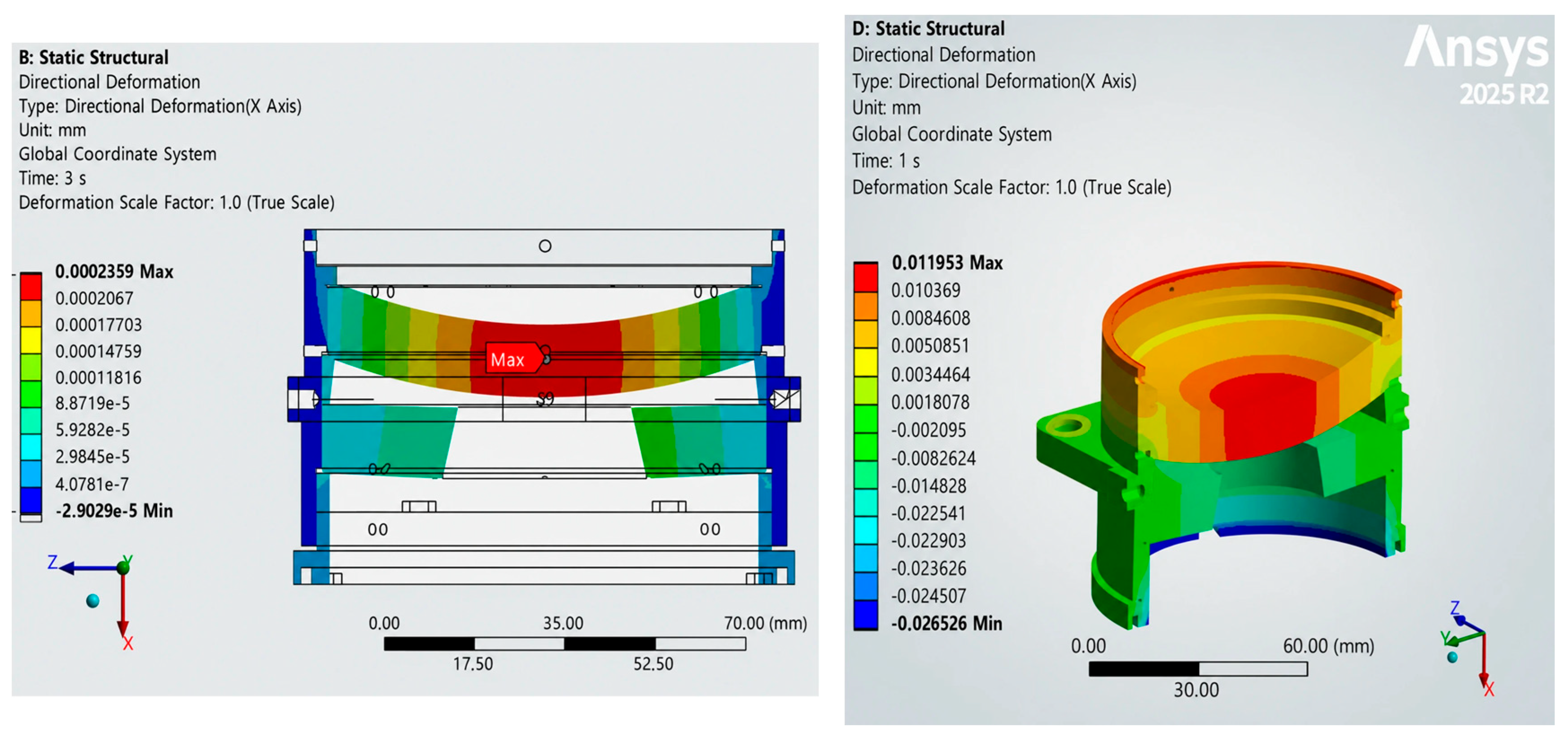
The lens-barrel design was analyzed to estimate possible alignment deviations caused by mechanical preload and temperature-induced deformation. Aspect ratios of the lenses make them sufficiently rigid to mechanical loads when preloading the retainer with forces necessary to withstand axial and transverse quasi-static launch accelerations. However, the rim-mounting method makes the optics susceptible to possible thermomechanical deformations resulting from differences in CTE. As seen from Figure 5 below, when simulating an extreme case of shrinkage occurring with temperature drop from 22 °C to −20 °C with initial radial clearance set to zero, the first lens with its coated surface acting as a second mirror may bend towards the primary mirror. In reality, the lens will be tilted within radial clearance after assembly, and instead of uniform pressure along its rim it will experience bending along the radial axis, but such extreme cases are being analyzed for estimating necessary tolerancing and thermomechanical compensations in order to avoid misalignment.
Figure 5.
(Left): Deformations along the main axis when applying a total preload of 200 N through retainer and baffle-holder acting as a counter nut; (Right): deformations along the main axis occurring with temperature drop from 22 °C to −20 °C with initial radial clearance set to zero.
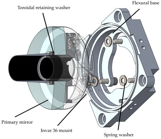
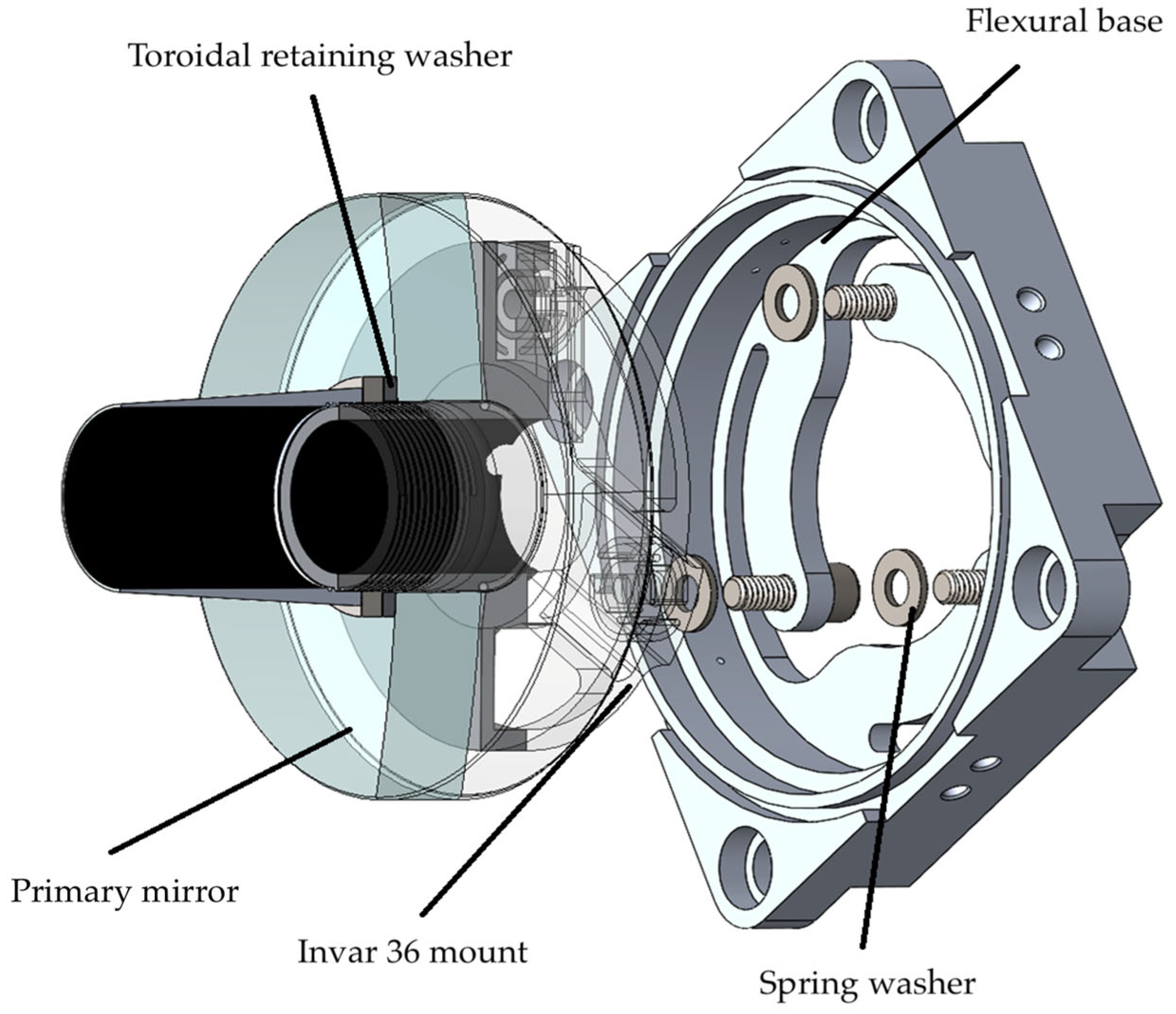
The relatively small size and high thickness of the primary mirror (PM) allow for a nonkinematic, central hub-style design of its mount [23]. To closely match CTEs, this project will use the primary mirror mount made of Invar 36, with tangential seat for its convex second surface and a toroidal retaining washer for the concave first surface. To provide better alignment and stiffness, the mount will have toroidal radial protrusion to match the PM’s internal diameter, with the plane of contact containing the mirror’s center of gravity.
Connection of the PM mount to the instrument’s structure employs flexural principles, which will provide compensation for thermal expansion effects and partially isolate the mirror from random vibrations during launch [22]. The interface to the flexures will include spring washers, which will allow small axial and tilt adjustments of the mirror (see Figure 6). Another feature of the flexural design is the ability to significantly increase the thermal resistance of the PM-to-structure path to closely match that of the SM-to-structure path, which will provide better optical athermalization. The primary mirror subassembly and its connection to the flexural base are shown in Figure 6.
Figure 6.
Section view of the primary mirror subassembly. The mount is connected to the flexural base through spring washers (view simplified).
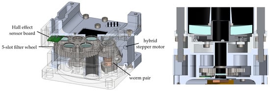
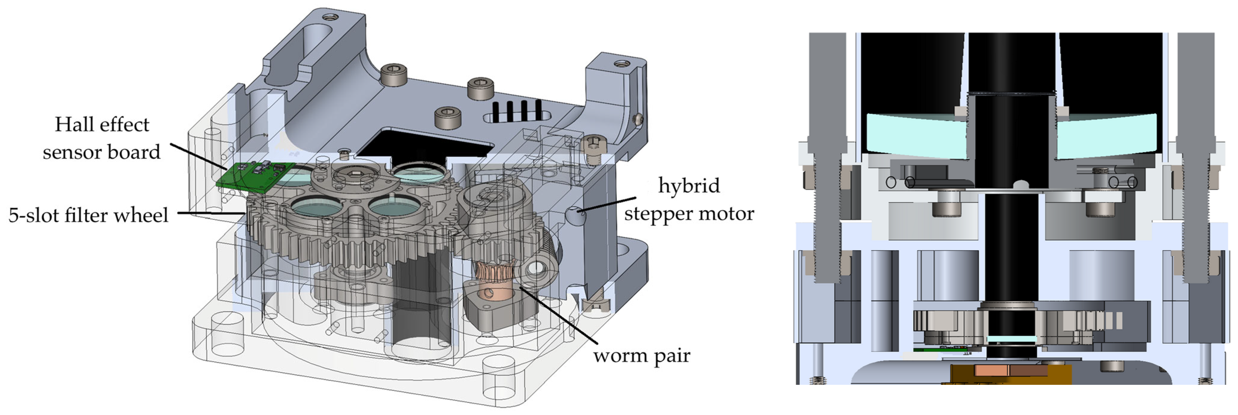
A worm gear system with a reduction ratio of 1:56 was designed to house and control the filter wheel with 5 optical slots. The worm gear was chosen due to a high reduction ratio in a compact configuration and 90-degree turn of the transmission. Additionally, a worm pair with a low lead angle was chosen for the self-locking feature, which adds to the stability of the system to vibrations. A vacuum-rated hybrid stepper motor with 1.8° step angle, coupled with high reduction ratio and additional clearance added to the filters’ diameters will provide high turn resolution and alignment robustness. An advantageous feature of the hybrid stepper motors is the existence of detent torque when turned off, which further adds to the resistance of the system. The filter wheel shaft subassembly features elastic bearing arrangement, which will enable small adjustments along the optical axis and provide resilience for vibrations and thermal effects, while the worm gear shaft has locating/nonlocating arrangement to compensate for manufacturing tolerances. A closed-loop control system using a Hall-Effect sensor is being implemented to tightly control the position of the wheel. The gearbox is housed in the Aluminum 7075-T6 frame, which will connect to the instrument’s optical structure through the PM’s base plate’s central cylindrical protrusion to control central alignment. The end face of the cylinder will register against the face of the gearbox frame subassembly, controlling axial position, and the whole frame will be secured in place by the Invar rods. The gearbox assembly of the wheel with filters and its connection to the optical system are shown in Figure 7.
Figure 7.
Filter wheel gearbox assembly. (Left): Section view; (Right): connection to the optical system.
An important design aspect of the filter wheel gearbox is the choice of lubrication. Since the mechanism is intended to operate under vacuum and variable temperature conditions, low-outgassing and space-compatible lubricants are required to reduce the risk of contamination of optical surfaces. PTFE- and MoS2-based dry-film lubricants are therefore considered for the gear train, while WS2-based lubrication is planned for the bearings.
The main mechanical transmission paths considered in the model include the lens barrel, primary mirror mount, Invar support rods, titanium external fixtures, primary mirror base, and filter-wheel gearbox frame. Mechanical coupling between rigidly connected parts was represented using simplified fixed or bonded interfaces, while the spacecraft-interface points were used as the main support locations. The use of Invar 36 elements and flexural mounting principles was selected to reduce thermoelastic misalignment of the optical elements.
The present work does not include a full transient orbital thermal-balance model. Therefore, environmental heat fluxes such as solar radiation, Earth infrared radiation, albedo, internal heat dissipation, and detailed conductive/radiative heat exchange between all payload components were not explicitly modeled at this stage. These aspects will be considered during the next stage of detailed thermal design and during thermal-vacuum testing of the assembled payload.
3. Results
3.1. Optical System
The payload optical system was developed considering the constraints of CubeSat and nanosatellite platforms. The system is required to provide a spatial resolution of no worse than 15 m (GSD) at a nominal orbital altitude of 550 km, while the entire optical assembly must fit within a volume of no more than 3U.
The optical system was designed based on a modified Maksutov configuration using two meniscus lenses. This configuration was selected as a compromise between compactness, optical performance, manufacturability, and CubeSat integration constraints. The folded optical path allows an effective focal length of approximately 550 mm to be implemented within the limited 3U payload volume, while the meniscus elements provide aberration correction with a relatively small number of optical components. This is beneficial for alignment and mechanical stability. In addition, the rotationally symmetric optical elements are compatible with conventional grinding and polishing processes, and the compact layout simplifies integration with the filter wheel, detector, and support structure.
For an orbit of 550 km and the required spatial resolution of 15 m (GSD), the system focal length is determined by the expression
where H is the orbital altitude, p is the detector pixel size, and GSD is the required spatial resolution. For the given parameters, the focal length is approximately 550 mm.
The minimum telescope aperture diameter is determined by the diffraction limit
where λ is the minimum operating wavelength. For the detector used, the minimum wavelength is 1.2 μm. The calculation shows that the minimum aperture diameter is approximately 53.7 mm. Considering the CubeSat platform volume constraints and the need to accommodate additional optical and mechanical components, the aperture diameter was chosen to be 84 mm.
The wavelength λ = 1.2 μm was used only for the preliminary diffraction-based estimation of the minimum aperture diameter. This represents the shortest wavelength of the operating range and therefore provides a conservative estimate for aperture selection. The complete optical performance was not evaluated using this wavelength alone. Instead, the MTF was calculated separately for the central wavelengths of the selected SWIR bands, namely 1.24, 1.6, 1.9, and 2.1 μm, to assess image quality across the intended operating spectral range.
The telescope field of view (FoV) is determined by
where SW is the swath width. For a 640 × 512 detector with a 15 μm pixel pitch, the horizontal detector size is 9.6 mm, while the diagonal size is approximately 12.3 mm. With an effective focal length of 550 mm, this corresponds to a diagonal FoV of approximately 1.28°.
The telescope f-number is calculated as the ratio of the focal length to the aperture diameter:
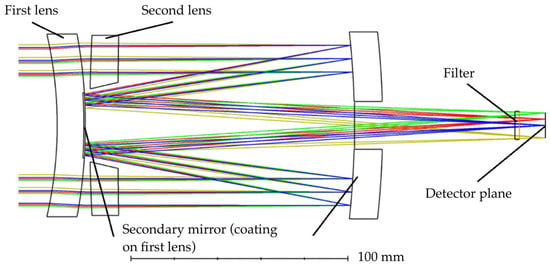
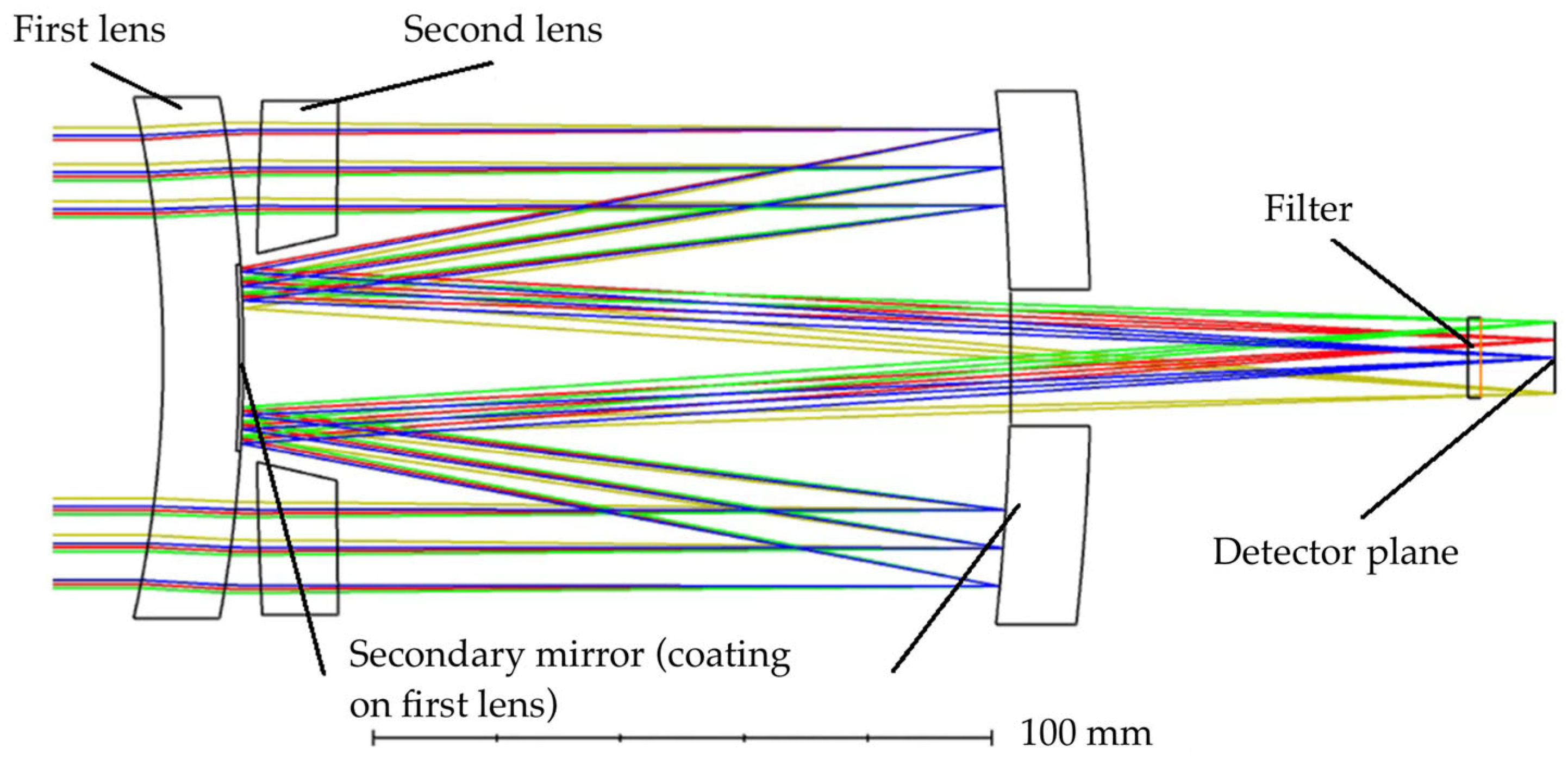
The optical layout of the system is shown in Figure 8.
Figure 8.
Optical layout of the modified Maksutov telescope.
Figure 8 shows the spatial configuration of the modified Maksutov optical system and the nominal ray path used for subsequent MTF and thermo-optical calculations. The system includes two meniscus lenses, a primary mirror, a secondary mirror formed by a reflective coating on the first meniscus lens, a filter-wheel plane, and a detector plane. The second meniscus lens has a central aperture, the inner walls of which can serve as a baffle for the secondary-mirror region. All linear dimensions in the figure are given in millimeters.
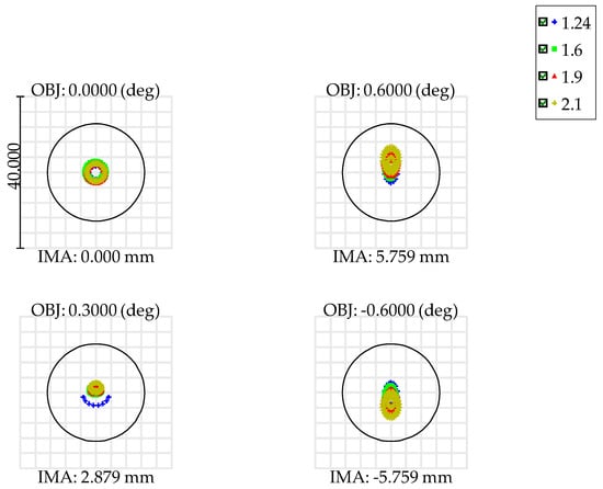
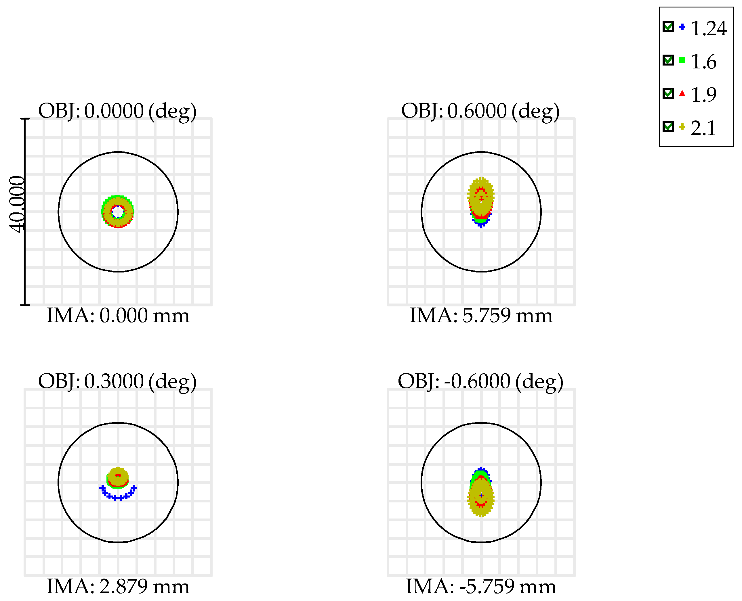
This configuration allows for a compact optical system with good aberration correction, which is particularly important for small satellite platforms. The spot diagrams of the optical system at different field positions and SWIR wavelengths are shown in Figure 9. The diagrams show ray distributions in the image plane for field angles of 0.0°, 0.3°, +0.6°, and −0.6° at wavelengths of 1.24, 1.6, 1.9, and 2.1 μm.
Figure 9.
Spot diagrams of the optical system at different field positions and SWIR wavelengths.
After the optical system layout was defined, its calculated characteristics were evaluated using MTF. This parameter was used as the main criterion of image quality, since it shows the ability of the system to transmit the contrast of fine details at a specified spatial frequency.
In the initial formulation, the requirement for the four SWIR bands was to maintain MTF above 0.1 at the Nyquist frequency of 33 lp/mm. The optical system was calculated for four spectral bands with wavelengths of 1.24, 1.6, 1.9, and 2.1 µm.
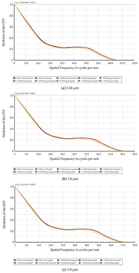
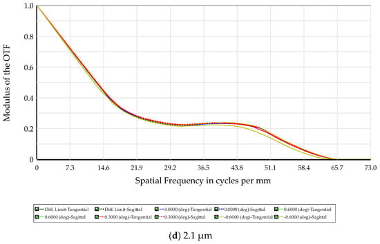
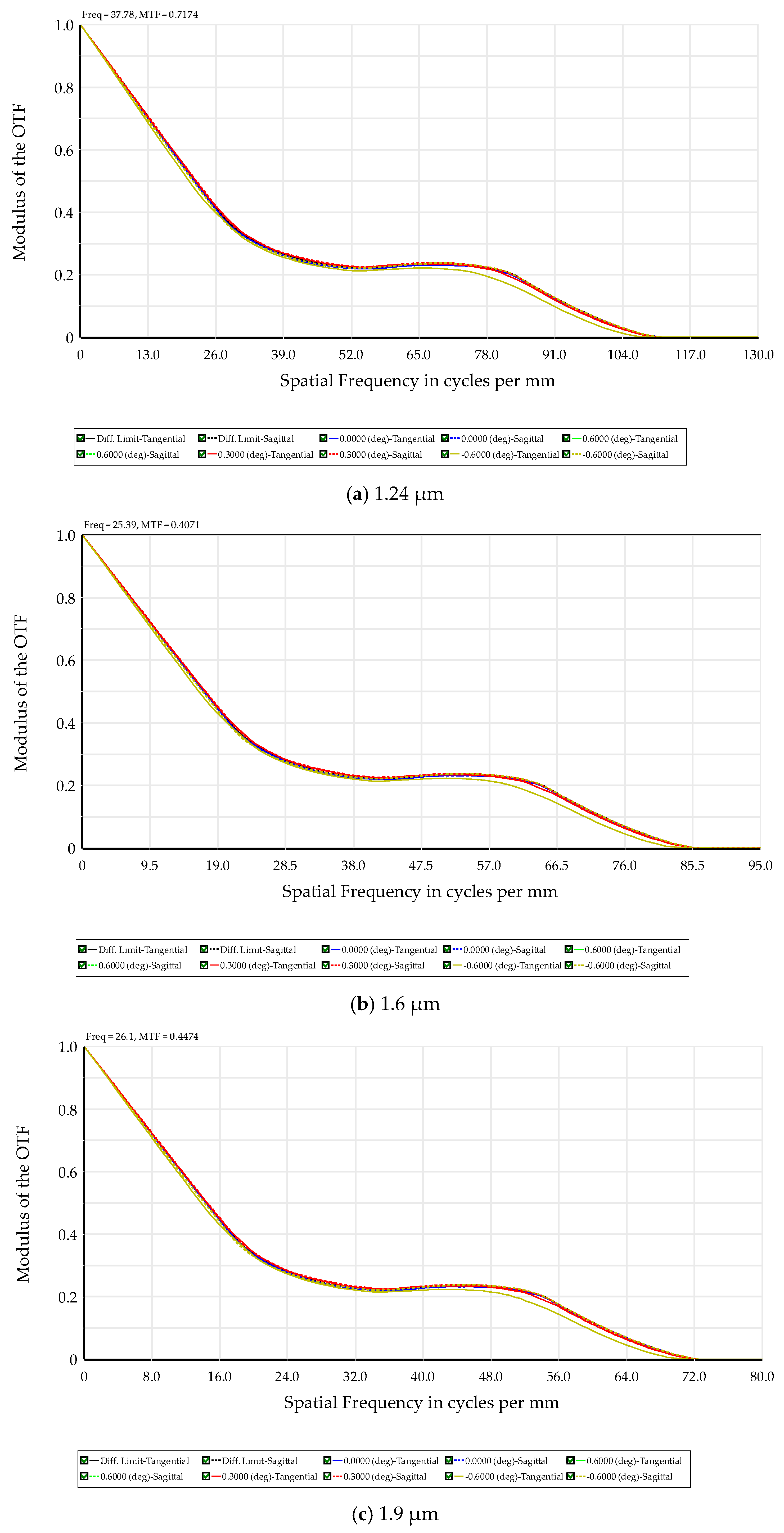
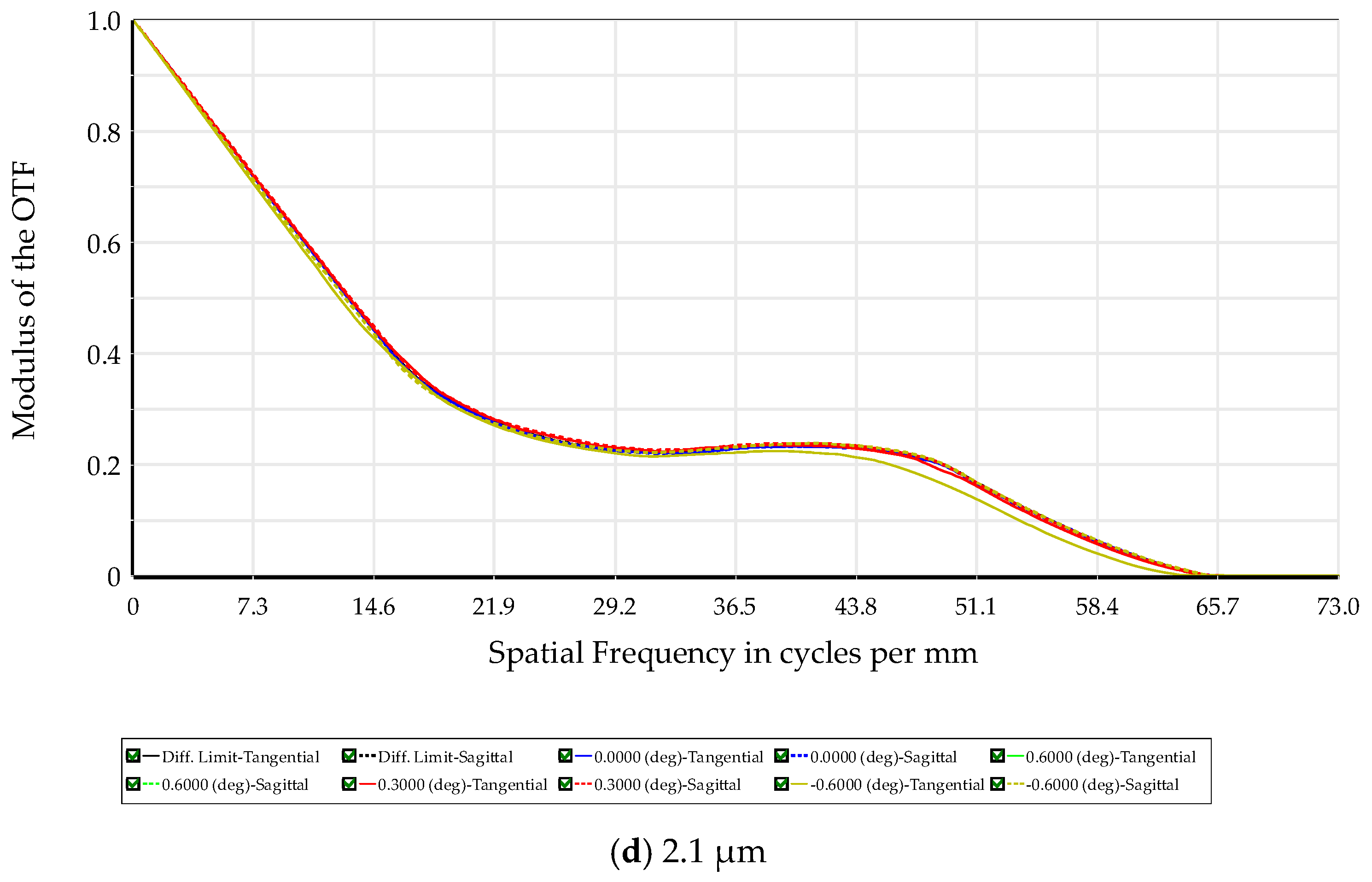
Figure 10 presents the calculated MTF for four spectral bands of 1.24, 1.6, 1.9, and 2.1 μm. The calculation was performed for four field positions: 0.0°, 0.3°, +0.6°, and −0.6°. Figure 10 is used to verify that the optical system maintains sufficient image contrast at the detector Nyquist frequency across all selected SWIR bands and field positions.
Figure 10.
MTF of the optical system for the spectral bands: (a) 1.24 µm; (b) 1.6 µm; (c) 1.9 µm; (d) 2.1 µm.
The MTF curves show that, for all four spectral bands and all considered field positions, the MTF at the detector Nyquist frequency of 33 lp/mm remains above the selected threshold of 0.1.
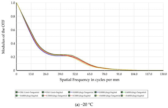
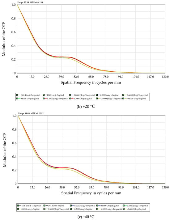
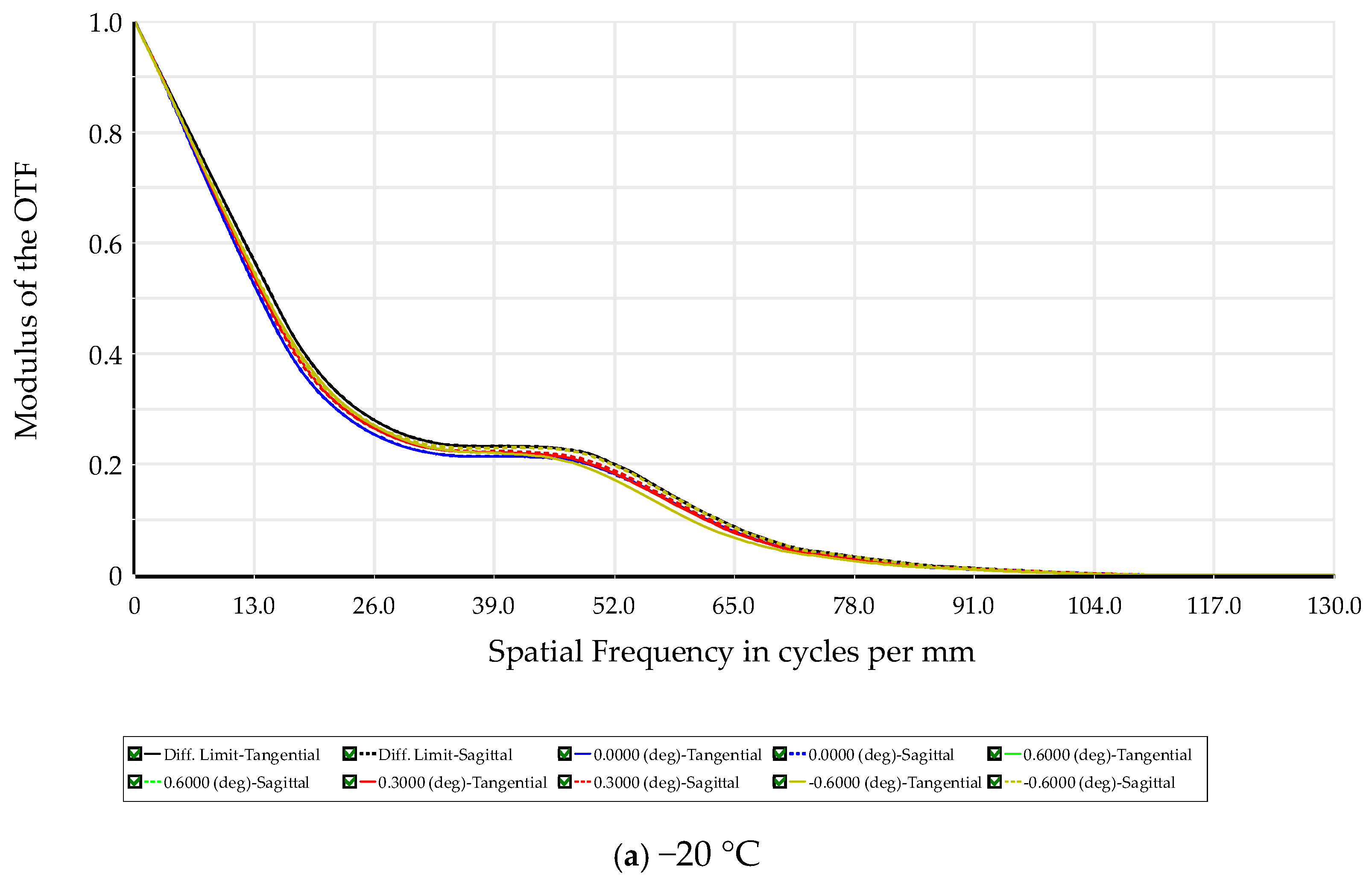
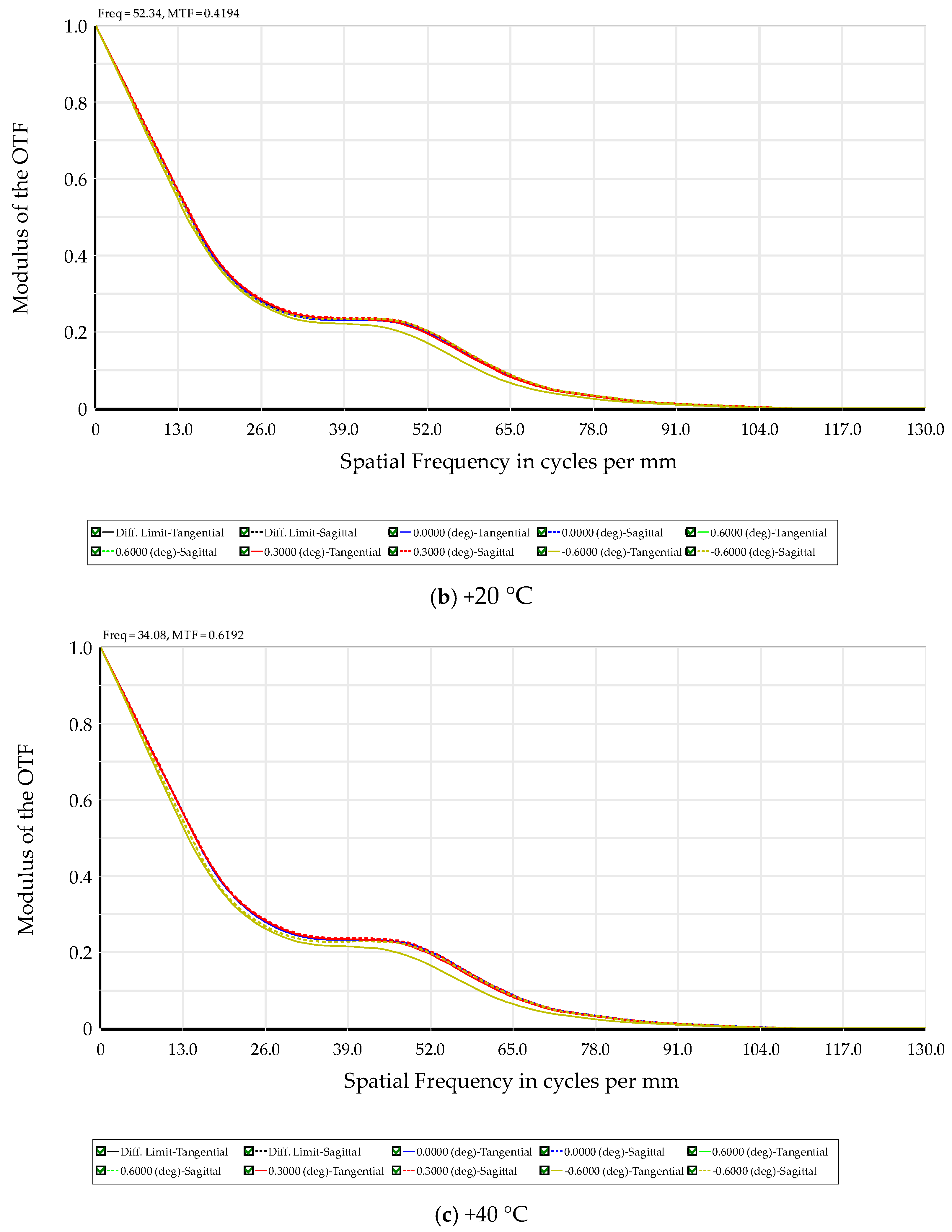
An analysis of the influence of ambient temperature changes on image quality was performed. The analysis was performed for temperature values of −20 °C, +20 °C, and +40 °C (Figure 11). This large temperature range is explained by the fact that active thermal control systems are not used for CubeSats, so the temperature variation will be high. These three modes were selected as the lower limit, intermediate state, and upper limit of the operating temperature range from −20 °C to +40 °C. The same temperature range was used in the thermo-optical sensitivity assessment of the optical system.
Figure 11.
MTF of the optical system at various temperature states: (a) −20 °C; (b) +20 °C; (c) +40 °C.
The MTF values in the region of 33 cycles/mm remain above the level of 0.1 for temperatures of −20 °C, +20 °C, and +40 °C. At the center of the field, 0.0°, the tangential and sagittal curves are close to each other. At the edges of the field, at angles of +0.6° and −0.6°, the difference between individual curves is more noticeable, especially in the region of medium spatial frequencies. At the same time, near 33 cycles/mm, the curves do not fall below the calculated threshold of 0.1.
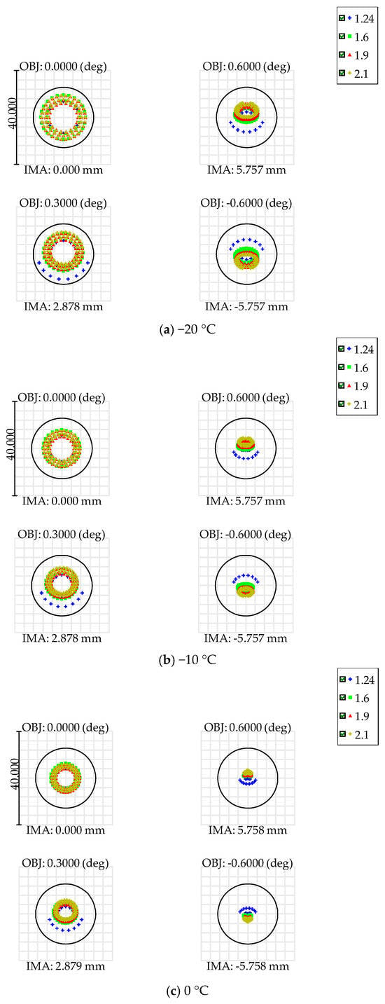
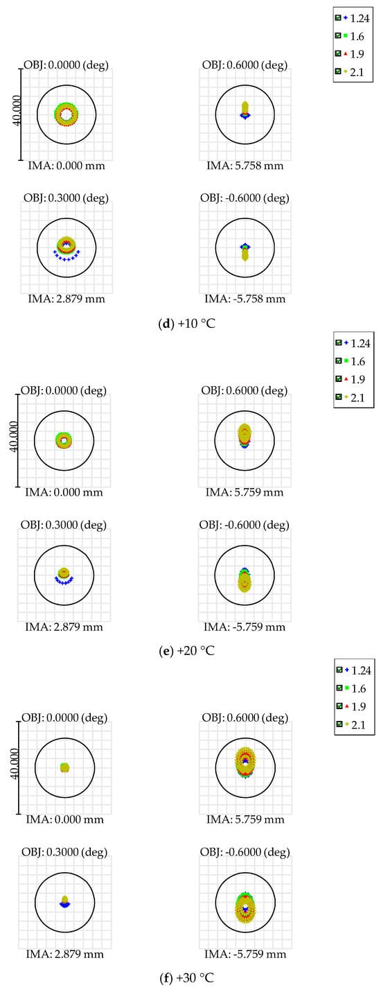
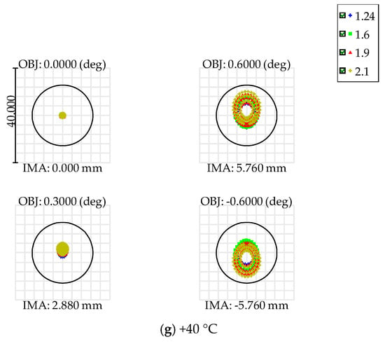
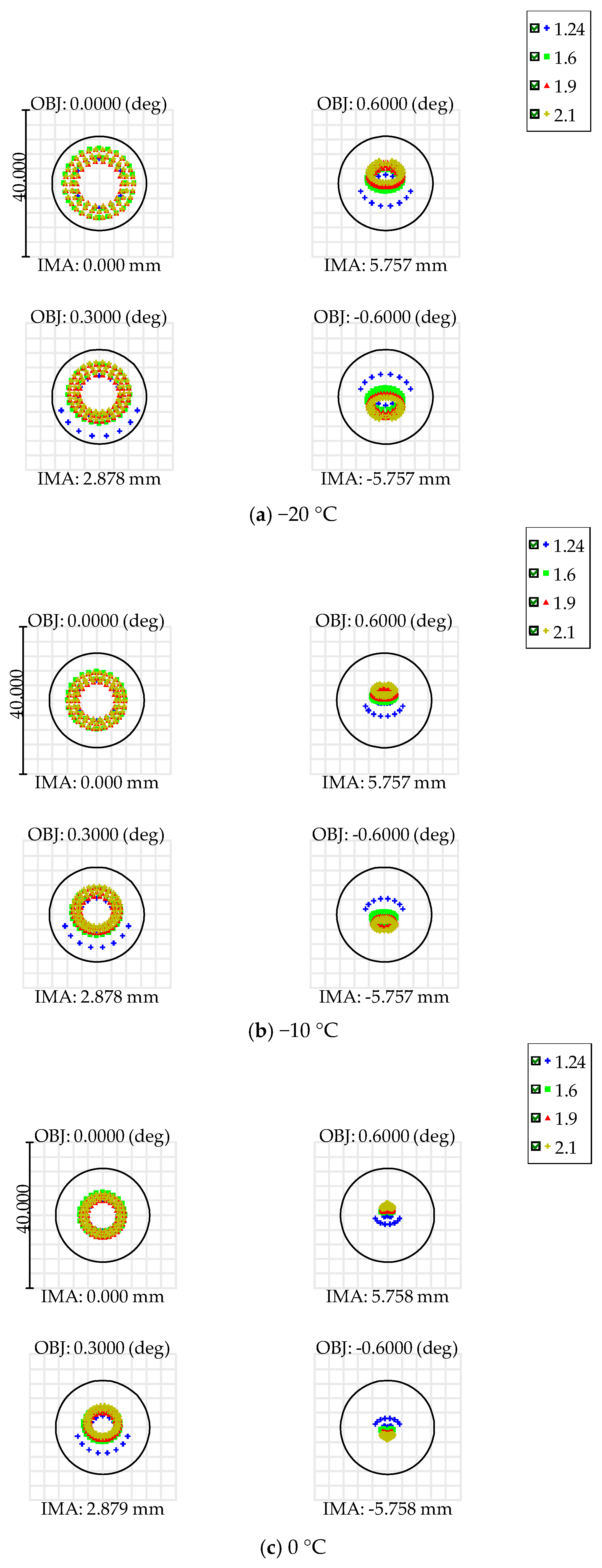
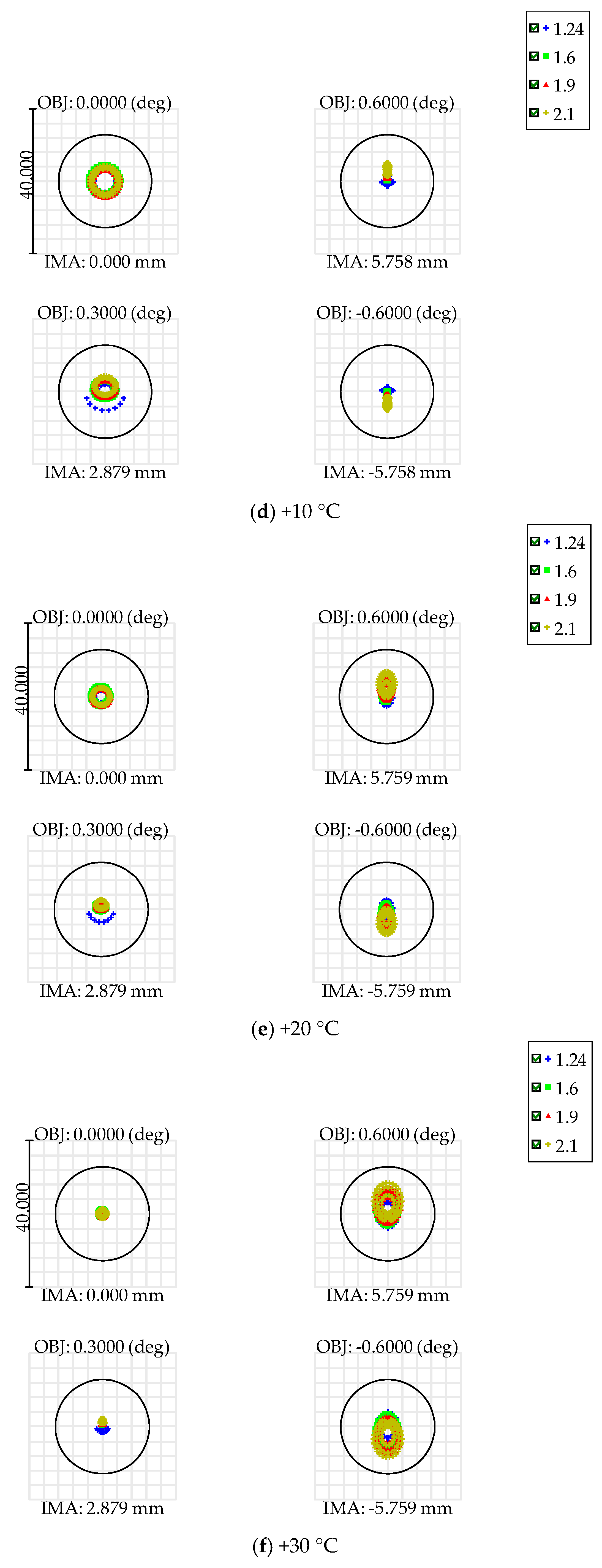
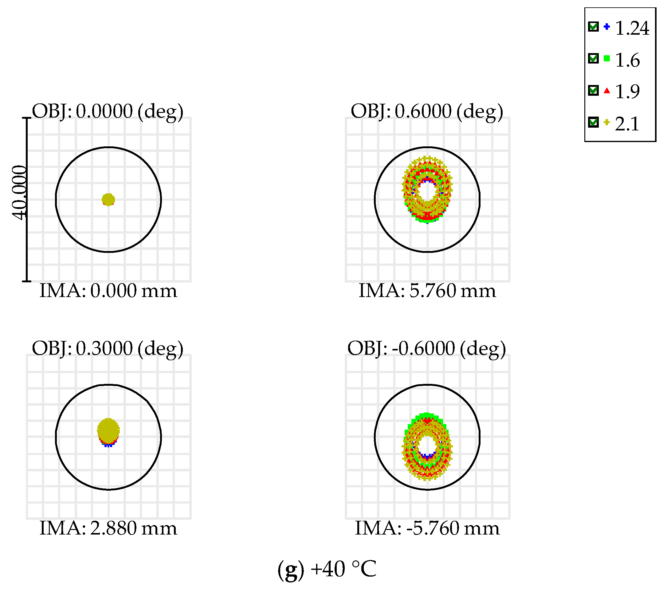
After the MTF analysis, an additional thermo-optical sensitivity assessment was performed to evaluate the influence of temperature-induced geometric changes on image formation quality. The modeling was carried out for seven temperature states in the range from −20 °C to +40 °C with a step of 10 °C. Figure 12 presents the point spread function diagrams obtained from the thermo-optical sensitivity assessment at different temperature states: −20 °C, −10 °C, 0 °C, +10 °C, +20 °C, +30 °C, and +40 °C. For each temperature state, results are given for four field positions: 0°, 0.3°, +0.6°, and −0.6°. The diagrams also show the four spectral bands with wavelengths of 1.24, 1.6, 1.9, and 2.1 µm.
Figure 12.
Point spread function diagrams of the optical system obtained from the thermo-optical sensitivity assessment at different temperature states: (a) −20 °C; (b) −10 °C; (c) 0 °C; (d) +10 °C; (e) +20 °C; (f) +30 °C; (g) +40 °C.
The figure shows that the shape and size of the spots change depending on the temperature state and field position. At the center of the field at 0°, the ray distribution remains more symmetric in most temperature cases. For off-axis field positions, especially at the field edges at +0.6° and −0.6°, the spots have a more pronounced elongated shape, which is associated with field aberrations of the optical system. When the temperature increases to +20…+40 °C, a change in the character of the ray distribution is noticeable in the off-axis field positions; however, the spots remain within the control circle shown in the diagrams.
3.2. Manufacturing of Optical Elements
One of the advantages of the studied optical system is that it utilizes only spherical surfaces, meaning that optical elements can be manufactured using traditional methods. Production can use low-cost machinery, can be easily set up using custom-made instruments, and is an affordable option for university groups and small companies. These projects’ set of optical elements for the compact SWIR payload was manufactured, ground, and polished in the production facility of AstroTechPribor (Almaty, Kazkahstan) with the participation of the authors. The manufactured set corresponds to the modified Maksutov-type optical layout used in the payload design and consists of three optical components with five optically functional surfaces. The components include: (1) a primary mirror with a central aperture, (2) a meniscus lens with a central aperture, and (3) a front meniscus corrector carrying a locally coated reflective zone that forms the secondary mirror. The relative position of these elements in the optical scheme is shown in Figure 8 above.
Fused silica blanks of JGS1 and JGS3 grades were used for manufacturing. This material choice follows the optical and optomechanical design logic of the payload: JGS3 is used for transmissive lens elements because of its suitability for the SWIR spectral range, whereas JGS1 is used for mirror-substrate applications where reflective coating is applied and the material provides high dimensional stability. The use of fused silica is also consistent with the requirement to reduce thermoelastic sensitivity of the optical train.
The photographs included in this section show intermediate manufacturing operations. They are intended to document the production route, pre-shaping, grinding, polishing, and dimensional-control stages, rather than final cleanroom inspection or coating qualification.
The manufacturing process included preparation of optical-component drawings, selection of the required grinding and polishing tools, and preparation of dedicated tool drawings. The blanks were bonded to mandrels for machining, central apertures were drilled where required, and diamond pre-shaping was performed on a lathe to obtain the initial geometry. Paired grinding and polishing tools were then manufactured, mutually lapped, and corrected based on radius-of-curvature measurements.
The optical surfaces were generated through a sequence of coarse and fine grinding operations. M40 abrasive was used for preliminary generation of the required radii of curvature, correction of element thickness, and reduction in runout or misalignment between optical surfaces. A typical material clearance of 0.8–1.0 mm was provided before this stage. After all elements were prepared for the transition to fine grinding, M10 abrasive was used. This transition was performed for the complete set of elements at the same time to avoid contamination of the fine grinding process by coarser M40 abrasive particles. A fine grinding step before polishing is necessary to eliminate micro-cracks and surface deformations caused by rough abrasive, and typically requires thickness reduction of 0.1 mm from each surface. The final surface preparation was carried out using polirit (cerium oxide) polishing compound. The principal manufacturing stages and corresponding process photographs are summarized in Table 4.
Table 4.
Conventional production sequence of the project’s optical components.





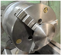
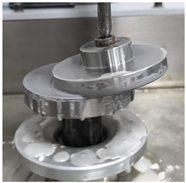
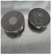
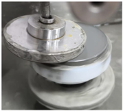
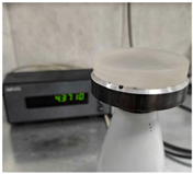
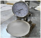
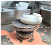
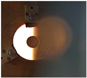
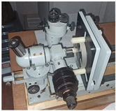
After polishing, the elements were subjected to dimensional inspection, including verification of the main geometric parameters, aperture dimensions, element thickness, and conformity with the optical drawings. Detailed interferometric surface-quality measurements, coating verification, and optical performance testing will be performed at the next stage after completion of the full optical assembly.
The manufacturing work confirmed the practical feasibility of producing the required three-element optical set for the compact SWIR payload using conventional grinding and polishing operations. Manufactured optical elements will be used for further assembly, alignment, and optical verification of the SWIR payload.
4. Discussion
The obtained results showed that the developed optical system provides a calculated GSD ≤ 15 m at an orbital altitude of up to 550 km. This value was achieved through the use of a modified Maksutov layout with an aperture of 84 mm and a focal length of approximately 550 mm. At the same time, the proposed configuration maintained compatibility within an allocated 3U volume allocated for the payload on the CubeSat platform.
The proposed payload occupies an intermediate engineering niche between compact spectral instruments with lower spatial resolution and larger optical payloads requiring greater platform resources. Its main advantage is the combination of a long effective focal length of approximately 550 mm, an aperture of 84 mm, and a filter-wheel-based band-selection mechanism within a compact CubeSat-compatible volume. Compared with hyperspectral or more complex multispectral architectures, the revolver filter wheel reduces optical complexity while still enabling sequential acquisition in selected SWIR bands. Compared with compact low-resolution spectral instruments, the proposed layout is aimed at improved spatial detail, with a calculated GSD of ≤15 m at an orbital altitude of 500–550 km. From a mission-level perspective, this configuration may be useful for CubeSat missions requiring targeted SWIR observations in several bands without the mass, volume, and power penalties of more complex optical payloads. A preliminary thermo-optical sensitivity assessment over the range from −20 °C to +40 °C indicated that the calculated influence of temperature-induced changes on image quality remains limited for the considered uniform temperature states. According to the MTF analysis presented in Figure 11, the MTF values remain above the selected threshold of 0.1 at the detector Nyquist frequency of 33 lp/mm. In addition, the spot diagrams in Figure 12 show that the ray distributions remain within the control circle over the analyzed temperature range. Unlike solutions in which phase-change materials are used primarily to stabilize the sensor temperature [17], this work focuses on preserving the optical geometry of the entire long-focal-length system. Compared with existing SWIR instruments for nanosatellites, the proposed payload is oriented toward higher spatial resolution while maintaining a compact configuration. For example, the FINCH EYE hyperspectral system, also adapted for a 3U CubeSat, is oriented toward a GSD of about 100 m [24]. In comparison, the proposed system has a calculated GSD approximately 6–7 times smaller, although it is inferior to FINCH EYE in spectral coverage. A similar design trade-off is observed when compared with the cameras of the DRAGO project: DRAGO-2 provides a resolution of about 50 m with similar compactness requirements [2].
Thus, the proposed four-band scheme occupies an intermediate niche between compact spectral instruments such as Argus 2000 and larger optical systems based on the Ritchey–Chrétien telescope, providing a balance between spatial detail (GSD ≤ 15 m), multiband capability, and the mass and dimensional constraints of the 3U platform [11,25,26]. Comparison with the TIRSAT system, which uses linear variable band-pass filters (LVBPFs), shows the difference in design approaches. Thus, the LVBPF architecture maximizes the compactness of the spectral unit, whereas the scheme with a filter wheel makes it possible to implement fixed spectral bands in combination with long-focal-length optics (f = 550 mm) to achieve high image detail [27].
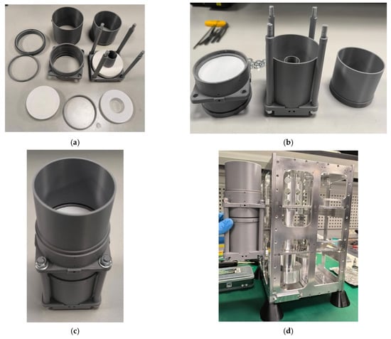
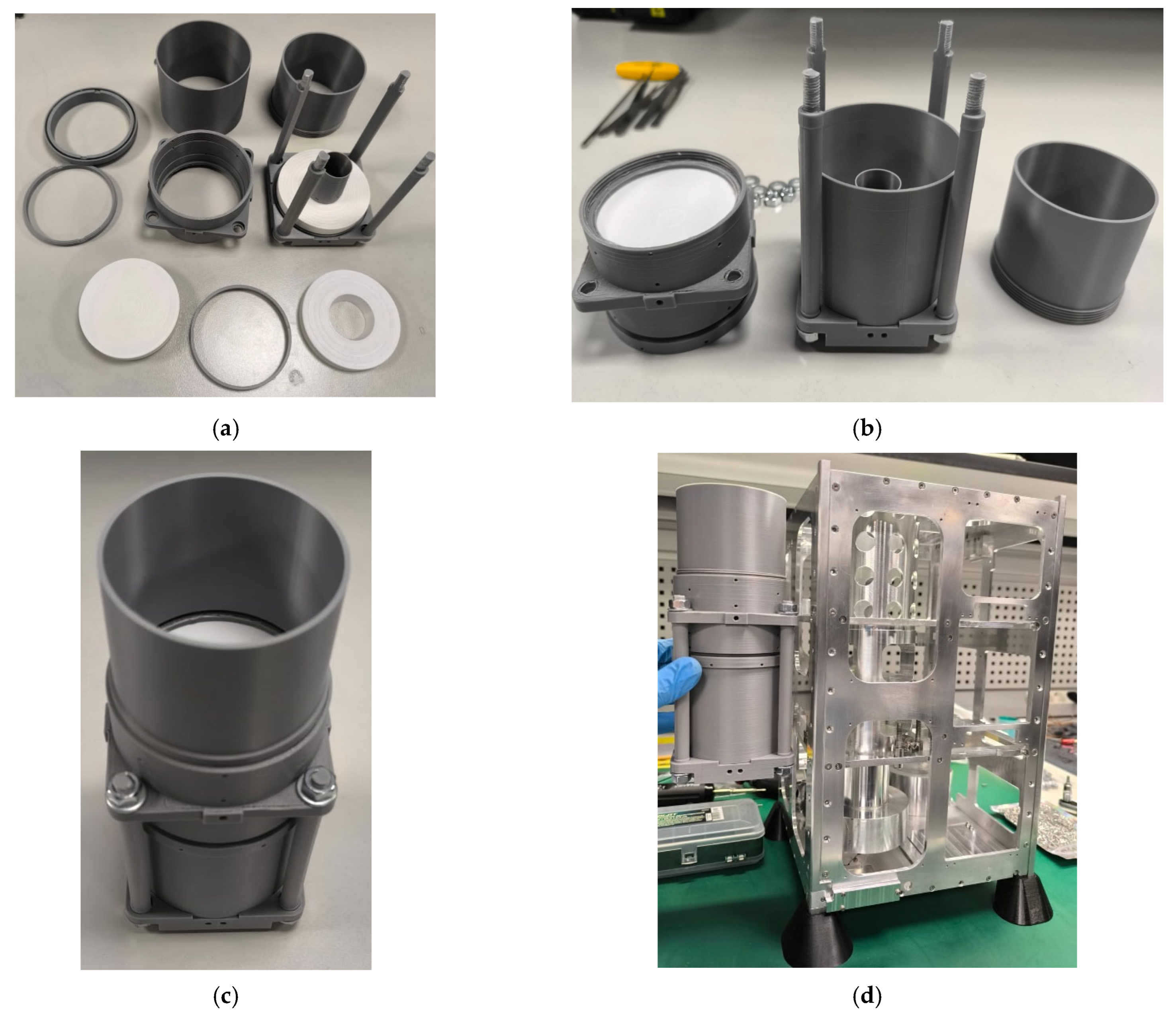
The hypothesis regarding the feasibility of placing long-focal-length SWIR optics within a 3U volume has been preliminarily confirmed at this stage by CAD modeling results. The authors assembled the first mock-up of this payload, on which the assembly sequence and access to fastening elements during assembly and alignment were verified. The elements for the first mock-up were printed on a 3D printer. Photographs of the structural and dimensional mock-up are shown in Figure 13. The 3D-printed mock-up was used only as a structural and dimensional model to verify assembly sequence, access to fastening elements, and compatibility with the spacecraft envelope. It was not used to validate optical performance, thermal stability, or mechanical stiffness. These characteristics will be verified using machined, flight-representative components made of the selected structural and optical materials. Therefore, the influence of 3D-printing material properties on the final performance assessment is excluded from the qualification logic.
Figure 13.
Structural and dimensional mock-up of the SWIR optical payload. (a) Set of elements; (b) Assembled primary and secondary mirror units before final assembly; (c) Optical part of the payload assembly; (d) Dimensional compatibility check with the structural model of a nano-class spacecraft.
To verify the calculated parameters, test procedures have been developed and are planned to be performed after completion of telescope assembly and alignment. The experience of the KITSUNE mission shows that real temperature gradients in orbit may differ from the calculated model by ±5 °C, which requires in situ verification of the thermal budget [16]. In addition, the payload performance evaluation methodology indicates the need for further verification of the signal-to-noise ratio, InGaAs detector stability, and radiometric characteristics of the instrument under conditions close to orbital operation [2,28].
The obtained spectral configuration also determines the applied orientation of the developed payload. The presence of four narrow bands at 1.24, 1.6, 1.9, and 2.1 µm makes it possible to consider the system for tasks of analyzing the mineral composition of the surface and assessing soil moisture [1]. At the same time, the 1.6 µm and 1.9 µm bands can be used to account for water vapor absorption and atmospheric effects, which increases the informativeness of subsequent thematic processing of Earth observation data [4,5]. Thus, the value of the proposed scheme lies not only in achieving the calculated GSD ≤ 15 m, but also in combining spatial detail with the targeted selection of SWIR bands.
Further work will focus on implementing the qualification program, including vibration testing according to the Falcon 9 profile and thermal-vacuum cycling [29]. Preliminary modal analysis of the selected Invar supporting elements showed the first bending mode at about 202 Hz, which indicates a sufficient stiffness margin relative to the system requirement above 100 Hz. During further experimental verification, it is necessary to control the vibration response of critical units of the optical system, including mirror mounts, the supporting structure, and the electronics unit. This approach is consistent with the results of vibration tests of optical payloads, where locally installed accelerometers made it possible to identify resonance modes and evaluate the dynamic stability of the structure [22].
The present study should be regarded as a design-stage numerical verification of the proposed payload architecture. The validity of the model was supported by several consistency checks. First, the main optical parameters, including focal length, aperture, FoV, and GSD, were verified analytically. Second, a Monte Carlo tolerance analysis with 1000 iterations was performed to evaluate the sensitivity of the optical performance to manufacturing and alignment errors. Third, the thermo-optical model was assessed by comparing MTF and PSF behavior at different temperature states. Final validation of the numerical model will be performed after assembly and alignment by optical testing, vibration testing, and thermal-vacuum testing.
5. Conclusions
In this work, a compact SWIR optical payload for a CubeSat nanosatellite platform was developed and numerically assessed. The proposed solution combines a long-focal-length optical layout, a compact optomechanical configuration, a structure designed to reduce thermoelastic sensitivity, and the capability to switch the spectral band using a revolver filter wheel.
The calculated results showed that the modified Maksutov layout with a focal length of approximately 550 mm and an aperture of 84 mm makes it possible to provide GSD ≤ 15 m at an orbital altitude of 550 km. The MTF analysis confirmed the preservation of image quality at the Nyquist frequency of 33 lp/mm for the four selected SWIR bands of 1.24, 1.6, 1.9, and 2.1 μm. A preliminary thermo-optical sensitivity assessment over the range from −20 °C to +40 °C indicated that the MTF remains above the selected threshold of 0.1 at the detector Nyquist frequency for the considered uniform temperature states.
The possibility of sequential imaging in several spectral bands increases the functional and scientific significance of the payload, allowing images of the same scene at different wavelengths to be compared. At the same time, the use of a filter wheel makes it possible to switch bands without complicating the system into a full multispectral or hyperspectral architecture.
At this stage, the calculated feasibility of placing long-focal-length SWIR optics within the limited volume of a CubeSat has been confirmed. Further work will be directed toward completing assembly, developing software for controlling the filter switching mechanism, optical alignment, and experimental verification of the system’s resistance to mechanical and thermal-vacuum effects.
6. Patents
The utility model patent "Service Platform of the Nano-Class Spacecraft" (Republic of Kazakhstan, No. 9516, 29 August 2024) resulted from the work reported in this manuscript.
Author Contributions
Conceptualization, D.A., B.Z. (Berik Zhumazhanov) and B.Z. (Beksultan Zhumazhanov); methodology, B.Z. (Beksultan Zhumazhanov) and A.K.; software, B.Z. (Beksultan Zhumazhanov) and D.A.; validation, B.Z. (Berik Zhumazhanov) and B.Z. (Beksultan Zhumazhanov); formal analysis, A.K. and B.Z. (Berik Zhumazhanov); investigation, A.K. and B.Z. (Beksultan Zhumazhanov); resources, A.K.; data curation, B.Z. (Berik Zhumazhanov); writing—original draft preparation, A.K. and D.A.; writing—review and editing, D.A., B.Z. (Berik Zhumazhanov) and A.K.; visualization, B.Z. (Beksultan Zhumazhanov); supervision, B.Z. (Berik Zhumazhanov) and A.K.; project administration, B.Z. (Berik Zhumazhanov), A.K. and B.Z. (Beksultan Zhumazhanov); funding acquisition, B.Z. (Beksultan Zhumazhanov) and B.Z. (Berik Zhumazhanov). All authors have read and agreed to the published version of the manuscript.
Funding
This research was funded by the Science Committee of the Ministry of Science and Higher Education, Research Identification Registration Number (IRN) BR27198365—Development of a short-wave infrared optoelectronic system in context of development of remote sensing space systems in Kazakhstan.
Data Availability Statement
The data presented in this study are available upon request from the corresponding authors.
Conflicts of Interest
The authors are employees of Ghalam LLP. The authors declare that the research was conducted in the absence of any commercial or financial relationship that could be construed as a potential conflict of interest.
Abbreviations
The following abbreviations are used in this manuscript:
| SWIR | Short-Wave Infrared |
| GSD | Ground Sampling Distance |
| MTF | Modulation Transfer Function |
| CTE | Coefficient of Thermal Expansion |
| FoV | Field of View |
| PM | Primary Mirror |
| SM | Secondary Mirror |
| LVBPF | Linear Variable Band-Pass Filter |
| SNR | Signal-to-Noise Ratio |
| CAD | Computer-Aided Design |
| U | Unit |
| PTFE | Polytetrafluoroethylene |
References
- Jenal, A.; Bareth, G.; Bolten, A.; Kneer, C.; Weber, I.; Bongartz, J. Development of a VNIR/SWIR multispectral imaging system for vegetation monitoring with unmanned aerial vehicles. Sensors 2019, 19, 5507. [Google Scholar] [CrossRef] [Scilit] [PubMed]
- Colodro-Conde, C. Performance Estimation of a Medium-Resolution Earth Observation Sensor Using Nanosatellite Replica. Sensors 2024, 24, 3160. [Google Scholar] [CrossRef] [Scilit] [PubMed]
- Miao, Y.; Lin, H.; Li, B.; Dong, T.; He, C.; Du, J.; Zhao, X.; Zhou, Z.; Su, J.; Wang, H.; et al. Review of Ge (GeSn) and InGaAs avalanche diodes operating in the SWIR spectral region. Nanomater 2023, 13, 606. [Google Scholar] [CrossRef] [Scilit]
- Li, J.; Yin, Z.; Lu, Z.; Ye, Y.; Zhang, F.; Shen, Q.; Zhang, B. Regional vicarious calibration of the SWIR-based atmospheric correction approach for MODIS-aqua measurements of highly turbid inland water. Remote Sens. 2019, 11, 1670. [Google Scholar] [CrossRef] [Scilit]
- Ikpaya, I.; Underwood, C. Towards high-temporal-resolution global monitoring of atmospheric carbon-dioxide using a compact spaceborne spatial heterodyne SWIR spectrometer: SHACS. Infrared Technol. Appl. 2023, 49, 12534. [Google Scholar]
- Pellegrino, A.; Pancalli, M.G.; Gianfermo, A.; Marzioli, P.; Curianò, F.; Angeletti, F.; Piergentili, F.; Santoni, F. HORUS: Multispectral and multiangle CubeSat mission targeting sub-kilometer remote sensing applications. Remote Sens. 2021, 13, 2399. [Google Scholar] [CrossRef] [Scilit]
- Ivliev, N.; Podlipnov, V.; Petrov, M.; Tkachenko, I.; Ivanushkin, M.; Fomchenkov, S.; Markushin, M.; Skidanov, R.; Khanenko, Y.; Nikonorov, A.; et al. 3U CubeSat-based hyperspectral remote sensing by Offner imaging hyperspectrometer with radially-fastened primary elements. Sensors 2024, 24, 2885. [Google Scholar] [CrossRef] [Scilit] [PubMed]
- Cho, D.H.; Choi, W.S.; Kim, M.K.; Kim, J.H.; Sim, E.; Kim, H.D. High-Resolution Image and Video CubeSat (HiREV): Development of Space Technology Test Platform Using a Low-Cost CubeSat Platform. Int. J. Aerosp. Eng. 2019, 2019, 8916416. [Google Scholar] [CrossRef] [Scilit]
- Buitrago-Leiva, J.N.; Terraza-Palanca, I.; Contreras-Benito, L.; Fernandez, L.; Gracia-Sola, G.; del Castillo Sancho, C.; Ha, L.; Camps, A. The 3Cat-4 spacecraft thermal analysis and thermal vacuum test campaign results. Aerospace 2024, 11, 805. [Google Scholar] [CrossRef] [Scilit]
- Smith, R.S.H.; Kraemer, F.; Bader, C.; Smith, M.; Weber, A.; Simone-Finstrom, M.; Wilson-Rich, N.; Oxman, N. A rapid fabrication methodology for payload modules, piloted for the observation of queen honey bees (Apis mellifera) in microgravity. Gravitational Space Res. 2021, 9, 104–114. [Google Scholar] [CrossRef] [Scilit]
- Jallad, A.H.; Marpu, P.; Abdul Aziz, Z.; Al Marar, A.; Awad, M. MeznSat—A 3U CubeSat for monitoring greenhouse gases using short wave infra-red spectrometry: Mission concept and analysis. Aerospace 2019, 6, 118. [Google Scholar] [CrossRef] [Scilit]
- Mayorova, V.; Morozov, A.; Golyak, I.; Golyak, I.; Lazarev, N.; Melnikova, V.; Rachkin, D.; Svirin, V.; Tenenbaum, S.; Vintaykin, I. Determination of greenhouse gas concentrations from the 16U CubeSat spacecraft using fourier transform infrared spectroscopy. Sensors 2023, 23, 6794. [Google Scholar] [CrossRef] [Scilit] [PubMed]
- Aoyanagi, Y. On-orbit demonstration of a linear variable band-pass filter-based miniaturized hyperspectral camera for CubeSats. J. Appl. Remote Sens. 2024, 18, 044512. [Google Scholar] [CrossRef] [Scilit]
- Pelliccia, F.; Minichini, R.; Salvato, M.; Barone, S.; dell’Aquila, S.D.; Esposito, V.; Madonna, M.; Mazzeo, A.; Salerno, I.; Verde, A. Preliminary design of a CubeSat in loose formation with ICEYE-X16 for plastic litter detection. Mater. Res. Proc. 2023, 37, 483–486. [Google Scholar] [CrossRef] [Scilit]
- Şanlı, A.; Erkeç, T.Y. Design and Analysis of Optical Telescope Subsystem. J. Aeronaut. Space Technol. 2024, 17, 92–101. [Google Scholar]
- Azami, M.H.B.; Orger, N.C.; Schulz, V.H.; Oshiro, T.; Alarcon, J.R.C.; Maskey, A.; Nakayama, K.; Fukuda, Y.; Kojima, K.; Takashi, Y. Design and environmental testing of imaging payload for a 6 U CubeSat at low Earth orbit: KITSUNE mission. Front. Space Technol. 2022, 3, 1000219. [Google Scholar] [CrossRef] [Scilit]
- Geismayra, L.; Schummera, F.; Langer, M.; Binder, M.; Schlick, G. Thermo-Mechanical Design and Analysis of a Multispectral imaging Payload using Phase Change Material. In Proceedings of the International Astronautical Congress (IAC)—The CyberSpace Edition, Virtual, 12–14 October 2020; pp. 12–14. [Google Scholar]
- Rast, M.; Painter, T. Earth Observation Imaging Spectroscopy for Terrestrial Systems: An Overview of Its History, Techniques, and Applications of Its Missions. Surv. Geophys. 2019, 40, 303–331. [Google Scholar] [CrossRef] [Scilit]
- SpaceX, [Falcon User’s Guide, Falcon 9 Rideshare Program]. Available online: https://www.spacex.com/rideshare (accessed on 19 July 2026).
- European Space Agency. Ariane 5 Users’ Manual, revision 1; European Space Agency: Paris, France, 2011; pp. 1–271. [Google Scholar]
- Meena, B.R.; Tomar, S.; Sahay, A.; Panwar, H. Opto-Mechanical Design of Short Wave Infrared Camera for Small Satellite, in Advances in Small Satellite Technologies; Springer: Singapore, 2020; pp. 193–200. [Google Scholar]
- Akzhigitov, D.; Zhumazhanov, B.; Kulakayeva, A.; Zhumazhanov, B.; Kapar, A. Evaluation of the Mechanical Stability of Optical Payloads for Remote Sensing Satellites Based on Analysis and Testing Results. Sensors 2025, 25, 6546. [Google Scholar] [CrossRef] [Scilit] [PubMed]
- Yoder, P.R. Mounting Optics in Optical Instruments, 2nd ed.; SPIE Press: Bellingham, WA, USA, 2008. [Google Scholar] [CrossRef] [Scilit]
- Shofman, I.; Neto, M.G.; Ganesh, T.; He, K.; Armstrong, A.; Narkevich, K. FINCH EYE: The Optical and Optomechanical Design of a GRISM-based SWIR Hyperspectral Imaging Payload for a 3U CubeSat. arXiv 2025, arXiv:2506.17480. [Google Scholar]
- Zhumazhanov, B.R.; Zhetpisbayeva, A.; Kulakayeva, A.; Makhanov, K.; Zhumazhanov, B.S. Development and optimization of optical payload for nanosatellites with strict constraints. Eurasian Phys. Tech. J. 2025, 22, 111–119. [Google Scholar] [CrossRef] [Scilit]
- Akzhigitov, D.Z.; Zhumazhanov, B.S. Development of a four-band SWIR optical payload for an Earth remote sensing nanosatellite. In Proceedings of the SPIE 14106, Optical Design and Engineering X, 141060N, Strasbourg, France, 26 May 2026. [Google Scholar] [CrossRef] [Scilit]
- Aoyanagi, Y.; Doi, T.; Arai, H.; Shimada, Y.; Yasuda, M.; Yamazaki, T.; Sawazaki, H. On-Orbit Performance and Hyperspectral Data Processing of the TIRSAT CubeSat Mission. Remote Sens. 2025, 17, 1903. [Google Scholar] [CrossRef] [Scilit]
- Praks, J.; Mughal, M.R.; Vainio, R.; Janhunen, P.; Envall, J.; Oleynik, P.; Näsilä, A.; Leppinen, H.; Niemelä, P.; Slavinskis, A.; et al. Aalto-1, multi-payload CubeSat: Design, integration and launch. Acta Astronaut. 2021, 187, 370–383. [Google Scholar] [CrossRef] [Scilit]
- Falcon User’s Guide, version 8; Space Exploration Technologies Corp, SpaceX: Hawthorne, CA, USA, 2025.

Disclaimer/Publisher’s Note: The statements, opinions and data contained in all publications are solely those of the individual author(s) and contributor(s) and not of MDPI and/or the editor(s). MDPI and/or the editor(s) disclaim responsibility for any injury to people or property resulting from any ideas, methods, instructions or products referred to in the content. |
© 2026 by the authors. Licensee MDPI, Basel, Switzerland. This article is an open access article distributed under the terms and conditions of the Creative Commons Attribution (CC BY) license.