


Abstract
Sustainable aviation is an ever-growing field, with feasibility, safety, and longevity being key areas of concern. Future electric aircraft will rely on multiple energy sources. Batteries can provide a fast response to changes in power demands, and fuel cells offer high energy density for prolonged operation. This work has developed an energy management strategy (EMS) aimed to minimise the overall energy consumption from these sources. The EMS is further designed to respect the operational limits of each component. It investigates three EM approaches to account for the hydrogen consumption restriction, namely the unconstrained method, the fixed-limit method, and a novel depletion-aware method. The unconstrained method assumes there is an unlimited amount of hydrogen, meaning it uses 14.81% more hydrogen than is available, whereas the fixed-limit approach applies the maximum amount of hydrogen available within the fuel tank. However, when there is no hydrogen available, the fuel cell shuts down immediately. This work introduces a novel depletion-aware approach which is conscious of reaching the hydrogen supply minimum limit and, hence, allows for greater use of the battery energy during this period. This allows for better coordination between the battery and fuel cell. The three EMSs are simulated and verified in MATLAB/SIMULINK. The simulation results are then validated using software-in-the-loop in dSPACE. The work demonstrates that the depletion-aware approach has distinct benefits compared to the other two methods as it constrains the fuel consumption and allows a smoother transition between energy storage devices and provides a scalable energy management strategy applicable to a range of all-electric and hybrid-electric aircraft.
1. Introduction
The electrification of aviation is central to achieving the ambitions outlined in the Flightpath report, which calls for a 75% reduction in carbon emissions alongside significant decreases in noise pollution and dependence on fossil fuels [1]. Several electrical power system architectures are currently being explored to determine the optimum solution to achieve minimum weight and maximum performance. The architectures can vary from batteries used alongside traditional internal combustion engines to battery–fuel cell aircraft. The exploration of multiple power sources onboard the aircraft allows for enhanced benefits that include power availability and redundancy. However, rigorous management of the power split between the power sources is required throughout the flight mission to improve the overall system efficiency and reduce the total fuel consumption. This can be achieved by designing the appropriate EMS [2].
The main energy management strategy (EMS) categories are rule-based, instantaneous optimisation, global optimisation, and learning-based [3,4]. Rule-based strategies use predefined logic and “if–then” rules to control the power split. They are commonly implemented due to their simplicity and reliability, but often produce sub-optimal results [5]. The instantaneous optimisation techniques aim to achieve the optimum solution in real-time implementation and therefore lack in not always reaching the global solution. The global optimisation strategies give the global solution, aiming to find the optimum results using predefined mission profiles, although they suffer from not being real-time implementable and having long computation times [6]. Finally, the learning-based methods refer to the system’s capability to learn and improve using a trial-and-error mechanism from experiences and data without being programmed [7,8]. The drawbacks of learning-based methods include safety concerns if unseen events occur, with the methods being unpredictable, and being an online optimisation technique makes it difficult for real-time implementation.
Within this work, an instantaneous method, specifically the equivalent consumption minimisation strategy (ECMS), is employed for its real-time applicability. This enables the model to represent realistic aircraft flight cases, which can be transformed into practical onboard EMSs.
Systems have operating constraints that must be considered during design. Parameters being unconstrained render real-time implementation impractical. These constraints are defined in a variety of studies exploring ECMSs [9,10,11], which include limiting the battery state of charge (SOC), fuel cell (FC) power, and battery power. Some EMSs include additional constraints, such as limiting the FC power slew rate [12]. This prevents fast changes in current and, hence, avoids increased stresses on the FC. However, these studies do not explore limiting the fuel available onboard. The all-electric aircraft model within this paper explores the use of fuel cells and batteries as energy sources. In many studies [13,14], fuel cells are modelled as infinite energy sources when exploring EMSs, whereas batteries are sized for limited capacity and carefully considered for SOC. In contrast, this work constrains the FC according to the hydrogen available onboard. This provides a more realistic representation of aircraft operations and ensures that the EMS respects both FC and battery limitations throughout the entire mission duration. This paper considers the aforementioned operating constraints, including fuel availability, to develop the EMS.
EMSs that are designed for automotive applications, such as [15,16], do not have to consider the constraint of limited fuel usage; instead, fuel consumption is displayed, indicating the driver when to refuel. However, in aircraft, the hydrogen tank is predefined, and hydrogen onboard must last for the entire mission. This includes any additional amount of hydrogen required for fly by and diversions. Incorporating any additional hydrogen leads to heavier systems. Therefore, with limited battery energy, the fuel consumption must be optimised to reduce the overall aircraft weight while enabling the completion of a full mission by applying an EMS.
As mentioned above, most applications apply an unconstrained approach to fuel consumption within the EMS. The incorporation of limited fuel capacity along with battery energy constraints within the EMS is a novelty in this work as it reflects real-world scenarios. A fixed-limit approach was first implemented to constrain the fuel available. However, when there is no hydrogen available, the FC shuts down immediately. To avoid this occurrence, this work introduces a novel depletion-aware approach, which is conscious of reaching the hydrogen supply minimum limit. When this happens, it allows for greater use of the battery energy, allowing for a smoother transition between power sources. Of note is that the hydrogen tank sizing is outside the scope of this work.
This paper develops an ECMS which minimises hydrogen consumption of the FC and the equivalent consumption of the battery energy. Furthermore, this work introduces a feedback loop between the FC and the EMS to monitor the fuel consumption throughout the mission. This ensures that the FC is treated as a power source with limited energy available during a mission.
The proposed depletion-aware method differs from existing approaches because it considers the hydrogen consumption within the EMS. This creates an integrated feedback loop, reducing the chance of an aircraft running out of fuel mid-flight, whereas existing approaches such as adaptive ECMS, predictive ECMS, and model predictive control do not explore this additional constraint within the control strategy. The adaptive ECMS in [17] allows for the equivalence factor to vary depending on operating conditions and constraints of the system, such as limited battery SOC. Ref. [18] explores the adaptive ECMS for safety. However, neither of the adaptive approaches constrain the amount of hydrogen and rather focus on the equivalence factor to vary battery equivalent consumption, respecting battery usage constraints without considering fuel usage constraints. A predictive ECMS, like [19], can be used to forecast future flight phases and help achieve an increased reduction in hydrogen by considering a larger time domain than the instantaneous optimisation in conventional ECMS. Finally, model predictive control in [20,21] establishes an estimate for the expected power split for the following time step, with exploration on the effect of fuel consumption and component degradation. It is often more accurate than ECMSs at reducing fuel consumption of the fuel cell and the battery energy; however, it does not monitor or react to low fuel availability and would have to be adapted for this purpose. Hence, the use of model predictive control does not solve the problem of fuel availability constraints.
This work is limited to the studies shown within this paper and does not compare to work from other authors, as there is no strategy available for limiting the hydrogen available within the EMS. Also, it is limited to the hydrogen consumption data obtained and does not explore a variety of aircraft sizing. The method has been tested on a small aircraft of half the size, but this reduces the amount of fuel cells and batteries, rather than changing the size of components.
This paper is arranged into five main sections, starting with the introduction. Section 2 introduces the aircraft architecture under study. Section 3 covers the methodology applied for FC sizing and the EMSs implemented. Section 4 displays the validation of the EMS, ensuring that the control strategy behaves as expected. Section 5 shows the results from testing the proposed modelling approach on an aircraft design with applied mission profiles. Finally, Section 6 concludes the work and states the direction of future work.
2. Aircraft Architecture
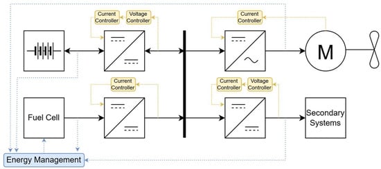
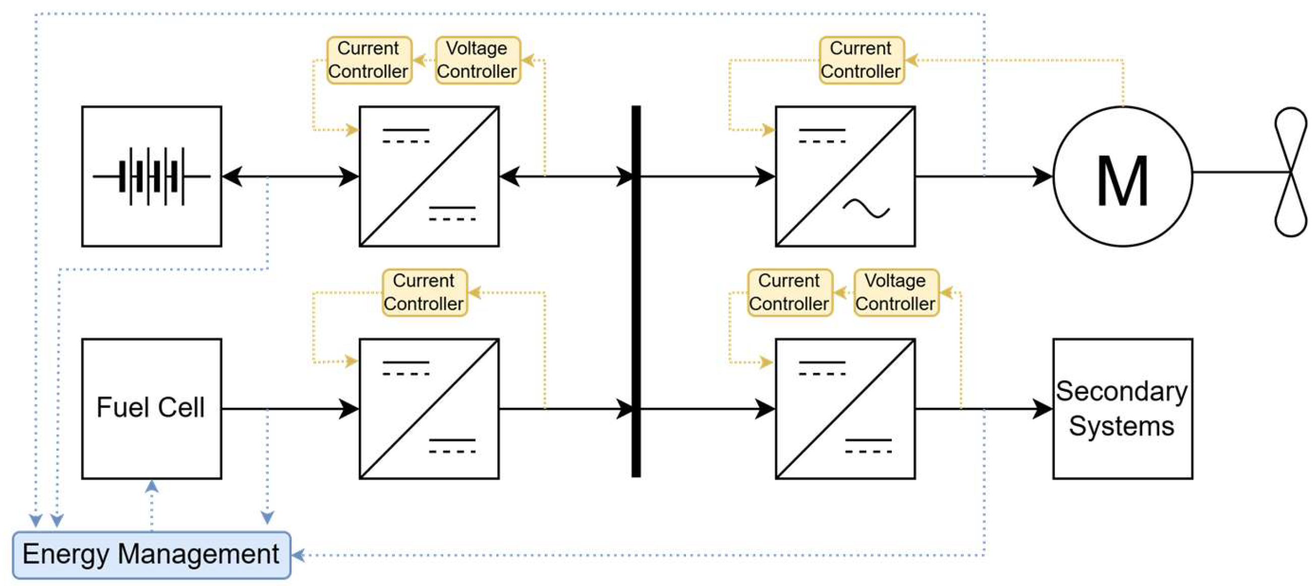
This paper explores a fully electric aircraft design, as shown in Figure 1, for a light aircraft with up to two passengers. The electrical power system (EPS) consists of one FC and one battery to power both the propulsion system and secondary systems. It operates at a bus voltage of 650 V. The simple architecture allows for the system to be tested on a small scale, with the potential to scale up for larger aircraft.
Figure 1.
Representative EPS architecture under study.
As shown in Figure 1, the battery is connected to the DC bus through a bidirectional power electronic converter (PEC) that allows for charging and discharging of the battery. The FC, in parallel to the battery, is connected to the DC bus through a unidirectional boost PEC. The DC bus powers the propulsion system, which consists of an AC motor driving a propeller, through a DC/AC inverter. The DC bus also feeds secondary power systems through a buck PEC, for the low-voltage loads, such as avionics and lighting. Figure 1 also depicts the connection of local controllers and the global energy management controller to the EPS.
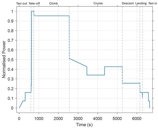
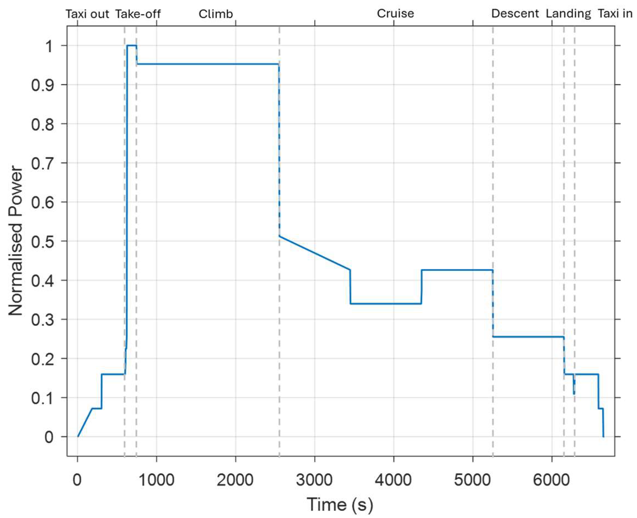
For this study, a typical mission profile has been assumed as depicted in Figure 2. This shows the normalised power against time for different flight stages including taxi out, take off, climb, cruise, descent, landing, and taxi in. This allows for the EPS and EMS model to be tested across the entire mission profile, ensuring sufficient energy is designed and made available for the whole mission of 6650 s.
Figure 2.
Mission profile, with dashed vertical lines showing the different flight stages.
3. Methodology
This work develops a methodology to design an EMS for aerospace applications that incorporates FC constraints and limited hydrogen availability within a mission.
Detailed modelling of the battery, power electronic converters, electric machine, and local controller architecture is beyond the scope of this paper and has been previously reported in [22]. However, this work has several limitations. There has been no sensitivity analysis for the parameters in this paper, with values preset, such as the equivalence factor for splitting battery and fuel cell powers. Thermal constraints are considered only during the system sizing process, and a comprehensive thermal model has not been developed to evaluate performance throughout the mission profile. In addition, the study investigates only one category of EMSs for integrating fuel availability constraints. The primary focus of this work is on the development and integration of the overall system, rather than on achieving further optimisation or refinement of system performance.
3.1. Energy Management Strategy Overview
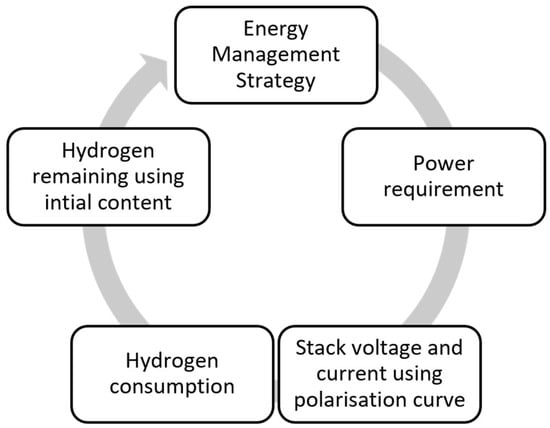
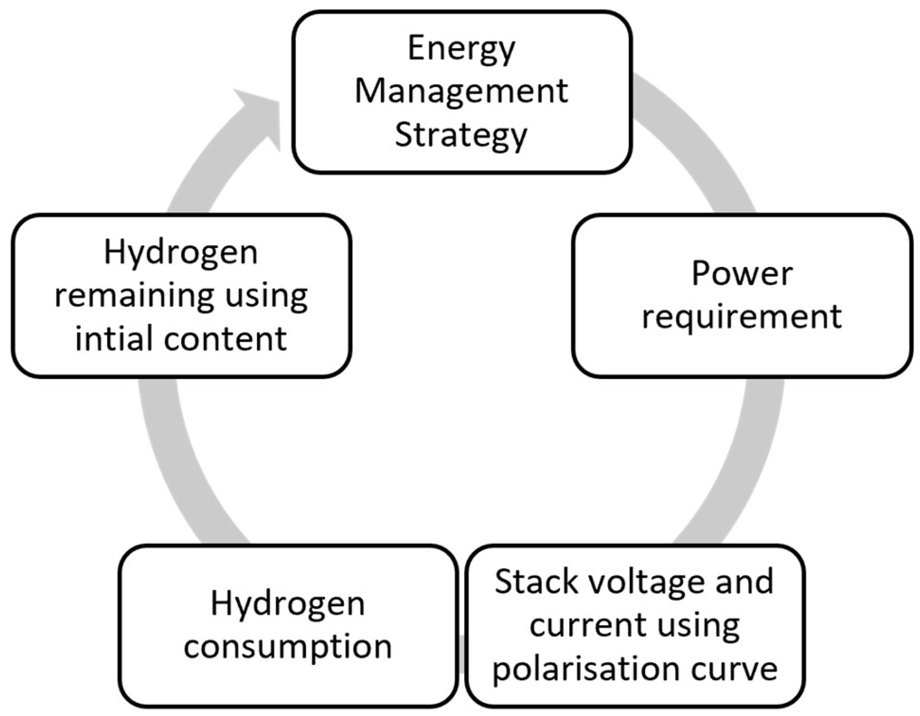
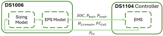
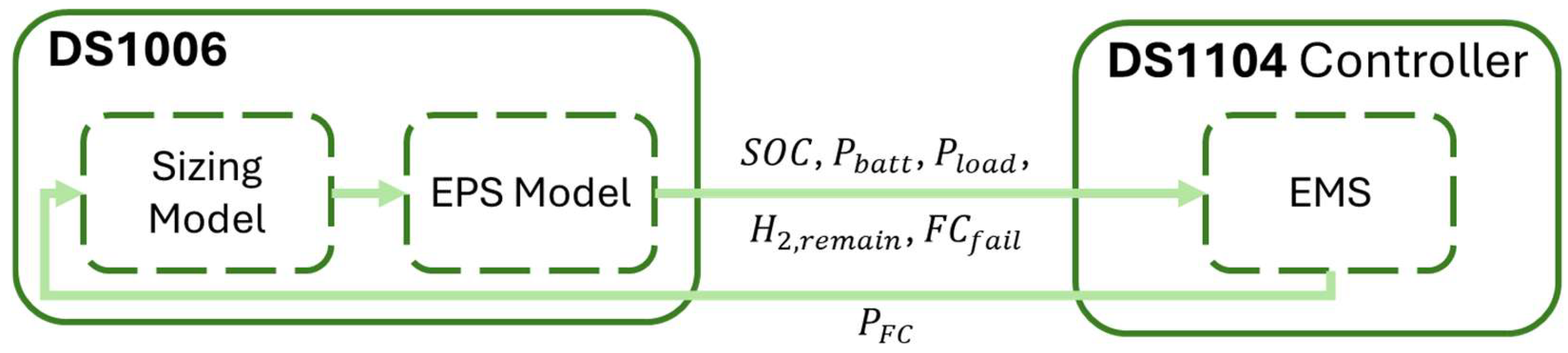
Introducing a limit to the hydrogen onboard the aircraft increases complexity within the EMS. The implementation of hydrogen consumption into the FC model causes a feedback loop between the FC model, including the hydrogen tank, and the designed EMS, as shown in Figure 3. This feedback loop is initialised assuming no power requirement for the FC. Then, as the EMS generates the power requirement, the FC stack voltage and current are determined. Based on the voltage value, the corresponding hydrogen consumption is computed based on an efficiency curve. With the initial hydrogen content within the tank and the computed hydrogen consumption, the hydrogen remaining is determined and fed back into the EMS. This feedback loop ensures that sufficient hydrogen remains to continue using the FC.
Figure 3.
Overview of energy management strategy.
From the feedback loop, two key parts of the methodology can be highlighted. The sizing model must be established to determine the amount of hydrogen onboard the aircraft at the start of a mission profile and continuous usage of hydrogen during the mission. The second part is the EMS, which determines the optimum FC power over a given mission profile to reduce hydrogen consumption.
The hydrogen remaining implemented within the EMS allows for restricted energy capacity onboard the aircraft. This is implemented into the model in three approaches: unconstrained hydrogen consumption, fixed-limit, and depletion-aware. These approaches will be explained in detail in the following sections.
3.2. Fuel Cell Stack Sizing/Modelling
The sizing of the FC and battery is essential for representing the fuel constraints onboard an aircraft. The battery is sized following an on-design and off-design method [23] to determine the battery energy capacity, control the state of charge, and respect the battery power limits within the EMS.
The FC sizing follows the approach in [24,25]. This determines the polarisation curve of a single cell, which plots the cell’s voltage against its current density. The cell polarisation curve can be scaled to the stack level. The polarisation curve of the fuel stack gives both the maximum power of the FC and current as a function of the voltage.
Using the FC output voltage as in Equation (1), the polarisation curve for one cell can be constructed. This equation comprises the Nerst voltage, ohmic voltage, activation voltage, and concentration voltage. The Nerst voltage equation (), as given in (2), is a thermodynamic equation that calculates the potential of an electrochemical cell, based on standard electrode potential, temperature, and concentrations of the reactants and products [26]. It is based on the Gibbs function , which is the thermodynamic potential of the water produced in liquid form; is the ideal gas constant with a value of 8.314 J/K·mol; is Faraday’s constant with a value of 96,485 C/mol; is the cell operating temperature; is the partial pressure of water; is the partial pressure of oxygen; and is the partial pressure of hydrogen [24]. The ohmic voltage () is the ohmic voltage drop from the resistances of proton flow in the electrolyte, with representing the current density (A/cm2) and the cell resistance, as shown in (3). The activation voltage () is the voltage loss due to the rate of reactions on the surface of the electrodes [27]. This voltage is given in (4), assuming is the exchange current density and is the transfer coefficient. Finally, the concentration voltage () is the voltage loss from the reduction in concentration gases or the transport mass of oxygen and hydrogen, as shown in (4), where is the amplification constant, is the mass transport constant, and is the limiting current density.
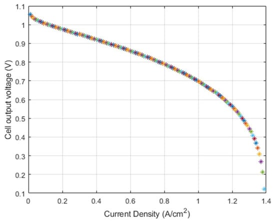
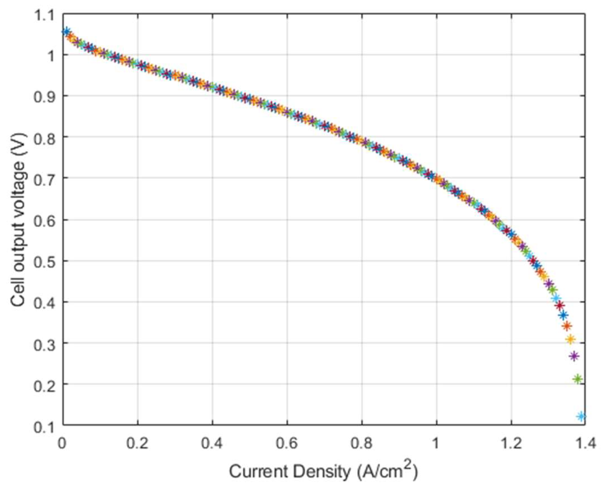
Using Equations (1)–(5), the polarisation curve for cell voltage against current density can be established in Figure 4. This polarisation curve is for one cell that is generated based on the parameters given in [23,24], and is used to determine the number of cells required. It shows the relationship between voltage and current density per cell by combining the ohmic, activation, and concentration loss regions into a single figure.
Figure 4.
Polarisation curve of a single cell within the fuel cell.
For the validation of the polarisation curve, it can be compared to the literature, such as in [28,29]. Figure 4 follows the same shape for the FC polarisation curve as that presented in the literature, with the exact values on the curve determined by the selected input parameters. The polarisation curves from experimental data in [30,31] cannot be reproduced due to the lack of data available. However, the same trends can be seen between the polarisation curves, justifying the use of Figure 4 within this work, with the modelling of the FC required as a feedforward loop for the EMS.
From this polarisation curve, the stack-level parameters can be assumed. This involves scaling up from cell level to stack level based on (6)–(8):
where is the number of cells in a stack, is the area of one cell, cm2, is the voltage at stack level, V, and is the current at stack level, A.
Considering a fixed cell area, the current at stack level can be found based on the known current density, as shown in (7). From this, the stack sizing can scale the polarisation plot into an entire FC stack polarisation plot, considering the output voltage in (6), current in (7), and stack power in (8).
The stack efficiency can be approximated using the cell voltage and the theoretical maximum voltage per cell:
From previous Equations (1)–(9), the FC stack polarisation curve can be produced. This can then be used for an approximation of the hydrogen fuel consumption, determined by
where is the mole of electrons per mole of fuel.
Next, the initial hydrogen requirement within the FC tank for sizing and filling the tank before a mission is determined using (11):
where is the low enthalpy value of hydrogen, is the FC power, and is the FC efficiency. The FC energy is calculated by integrating the power required over the mission profile shown in Figure 2 divided by the FC efficiency.
Hydrogen remaining at each instant of the mission is the initial hydrogen content minus the hydrogen consumed at that point.
The EMS takes in as input the hydrogen remaining and determines the power output of the FC by the equivalent consumption minimisation strategy as detailed in the Section 3.3.
3.3. Equivalent Consumption Minimisation Strategy
The EMS implemented follows the equivalent consumption minimisation strategy (ECMS) approach explained in [32]. This aims instantaneously to minimise the hydrogen consumption of the FC and the equivalent consumption of the battery energy. The selection of the equivalence factor was predetermined, and the exploration of alternative values was not outside the scope of this work. The minimisation function is given by
where
with being the hydrogen consumption of the FC, g/s, the equivalent consumption of the battery energy, g/s, the equivalence factor, and a constant that correlates to how strongly the SOC affects the equivalence factor. The battery is limited by the energy capacity available, which can be used to determine the SOC during a mission profile. This is incorporated within the EMS.
Typically, in most published works, the operational constraints do not consider the fuel remaining onboard. In this work, however, the EMS constraints incorporate the remaining fuel:
where is the battery power, kW, is the remaining hydrogen in the fuel tank, kg, is the FC power, kW, and is the rate of change for FC power, kW/s.
These updated constraints allow for more control over the EMS throughout the mission, considering a variety of unusual scenarios. Therefore, the design should be adaptable to any mission profile expected to be encountered throughout the aircraft’s service life.
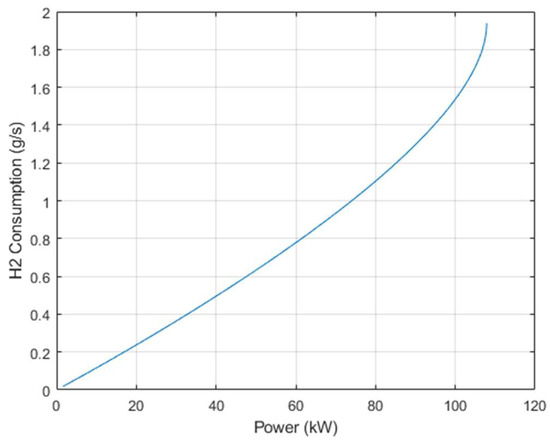
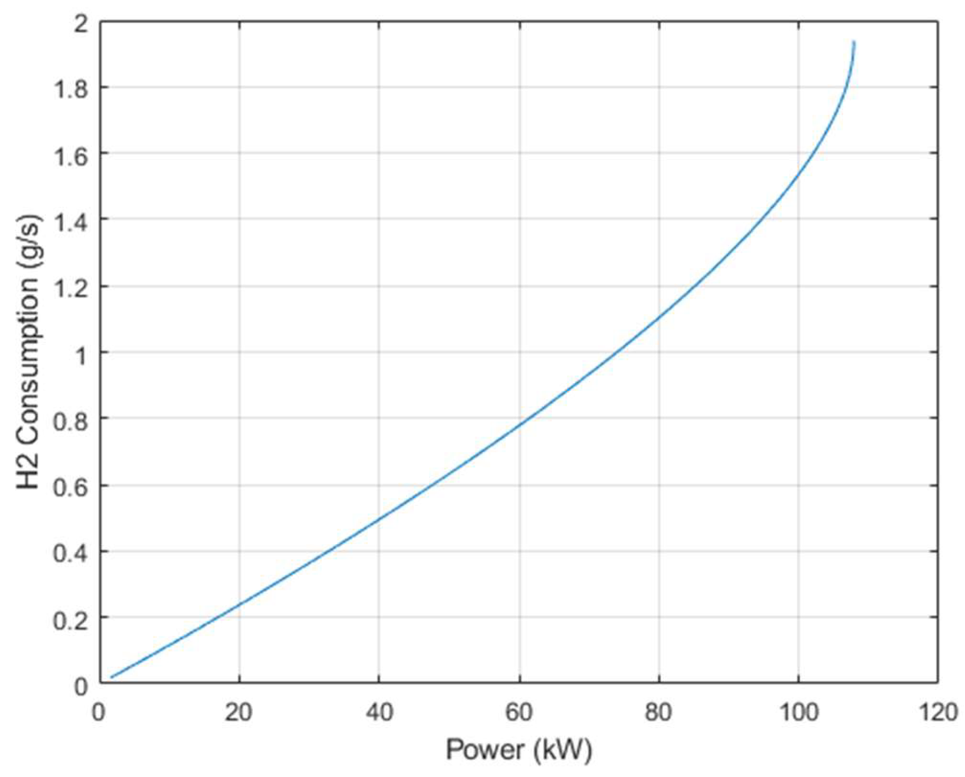
As a summary of the hydrogen equations, the hydrogen fuel tank sizing and hydrogen requirement for a mission are calculated using Equation (11). Equation (10) gives an approximation for hydrogen expected to be consumed during the mission. Figure 5 and Equation (15) below are also used for the hydrogen consumption but are usually given in the FC datasheet; therefore, they should be the most accurate, if known.
Figure 5.
Fuel cell hydrogen consumption with respect to power level.
The FC hydrogen consumption curve, shown in Figure 5, relates the FC power to the hydrogen consumption, and is required to determine the optimal battery power. As the power approaches its maximum rated power, the consumption rate increases due to the concentration losses. The fuel cell draws hydrogen and air faster than it can reach the reactant sites inside the cell, causing a bottleneck, which leads to a voltage drop while current continues to rise [33]. Therefore, consumption increases faster than power increases at this point. This curve in Figure 5 is usually given within the FC datasheet and can be used to determine the parameters for the FC consumption equation:
where , , and are the coefficients from the fuel consumption curve in Figure 5.
For the battery, charging and discharging efficiencies can differ, meaning that these should be taken into consideration when determining the battery equivalent consumption. These efficiencies for the battery charging and discharging are calculated by [10],
where is the battery open-circuit voltage.
Next, according to [32], the battery power consumption (), g/s, can be approximated by
where is the efficiency of the battery, is the average consumption of the FC, g/s, and is the corresponding average power of the FC, kW.
The FC and battery powers must fall within the constraints set in (13), and can be calculated using
where is the load power requested from the electrochemical energy units, kW, is the average consumption of the FC, g/s, and is the average FC power, kW [32].
The ECMS for determining the optimum FC power is represented by Equations (12)–(20).
The hydrogen remaining at different points in the mission profile is determined by
where is the initial hydrogen onboard the aircraft, kg. The hydrogen remaining is fed into the EMS to determine the power required for the next cycle.
Of note is that the constraint for the FC slew rate is a safety consideration which should be applied to the output power from the EMS. The power change between the time steps must be limited. Therefore, the battery must provide more power than the FC when the slew rate restricts the change in power levels, meaning that the FC consumption is restricted during this part of a mission profile.
Furthermore, the degradation of the battery can be monitored for comparison uses only, using experimental data and Equations (22) and (23), which can be found in [12,34]. The battery degradation is given by
where is the battery capacity, Ah, and is the cycle life of the battery.
The results of these battery degradation equations are displayed within Section 5.
3.4. Hydrogen Consumption Restriction
To implement the limited hydrogen fuel available within the EMS for an aircraft model, two different approaches are considered for the modelling. The first approach considers the fixed limit to fuel consumption, whereas the second approach, the depletion-aware strategy, suggests changing the equivalence factor and battery constraints as the FC is depleted. The unconstrained fuel consumption method is also presented.
3.4.1. Unconstrained Fuel Consumption
The unconstrained approach assumes that unlimited hydrogen is available within the fuel tank, assuming it is an infinite energy source. This approach is how EMSs are designed for the automotive industry. The EMS aims to reduce hydrogen consumption, with no fixed limit, as electric vehicles are typically refuelled before reaching full depletion. However, aircraft must manage the limited energy source available, which is predefined. Therefore, the unconstrained approach is not a true representation. Aircraft aim to limit excessive weight and hence reduce unnecessary fuel available on the aircraft.
Within this case, the feedback loop is broken, with the fuel consumption not necessary for calculations, and Equation (21) being for observational purposes only. This means that there is no feedback between the fuel consumed and the EMS. Therefore, only power requirements need to be determined in the FC sizing, without the need for hydrogen availability to be considered. This follows the approach in case studies [32].
3.4.2. Fixed Fuel Limit
Limiting the hydrogen consumption within the EMS works by applying a fixed limit to the amount of fuel available. This means that once it has reached the minimum allowable fuel remaining within the hydrogen tank, the FC will shut down. This is because no more hydrogen can be supplied, and the FC cannot provide additional power. This abrupt FC shutdown approach is often unfavourable as it causes stress on the FC stacks. However, without sufficient fuel, it may be required to ensure that the battery takes over and power is maintained throughout the flight.
For this fixed-fuel-limit approach, the FC is switched off once the remaining hydrogen reaches 10%, as shown by
where is the optimum FC power as determined by the EMS, such as the ECMS method using (20).
3.4.3. Depletion-Aware
The depletion-aware approach aims to reduce hydrogen consumption as the hydrogen fuel is depleted and increases battery usage. This can be enabled by allowing the equivalence factor to decrease, along with the SOC limits. Therefore, a greater reliance on the battery prolongs the remaining fuel for the given mission. For example, if an aircraft has an unexpected diversion, both the FC and battery can be used alongside each other to cover for longer and reduce single-source dependency. This prevents the FC hydrogen supply from being depleted immediately, avoiding an abrupt FC shutdown, which can induce stress on the FC stacks, degrade lifetime and reliability, and cause voltage spikes. Gradual reduction in FC output allows for increased control of operating conditions, such as thermal management, which may further mitigate internal hardware damage [35].
The SOC must be reduced gradually, in controlled increments, to avoid abrupt constraint changes while the battery regulates the DC bus voltage. However, the equivalence factor may be changed in larger increments according to the desired power split. The hydrogen thresholds were selected at three equally spaced intervals for demonstration of the method. Introducing more intervals would control the usage of hydrogen more accurately but also add complexity to the system and reduce the real-time calculation during validation of the method. The equivalence factors were selected to optimise the battery SOC increments. These decreases in stages for the SOC and equivalence factor according to the hydrogen remaining are shown in the equations:
where is the incremental decrease in SOC per time step, is the intermediate SOC, is the lowest SOC available for the battery, which is usually reserved for failure operational conditions, and represents the equivalence factor with 1, 2, and 3 denoting the decrease in equivalence factor values depending on hydrogen consumed.
In this strategy, Equation (24) is also applied so that the FC switches off once the fuel is depleted but allows for a smoother transition as the reliance on the fuel consumption is decreased and the battery provides more energy.
A sensitivity analysis of the hydrogen threshold values and equivalence factor could be conducted to further refine and optimise the results. However, this was beyond the scope of the present study and was therefore not undertaken.
4. Validation Platform
The methodology in the previous section was simulated within MATLAB/Simulink R2023b and then validated in the dSPACE ControlDesk 2022-B environment. Given the strong correspondence between the two sets of results, this paper focuses and reports only the dSPACE results, as they confirm the control system is performing as expected in real-time.
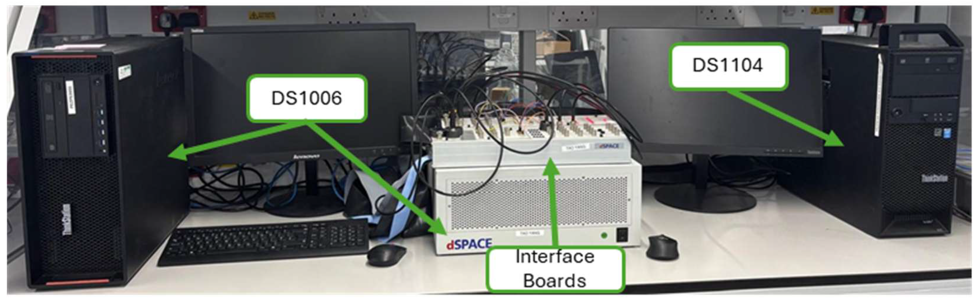
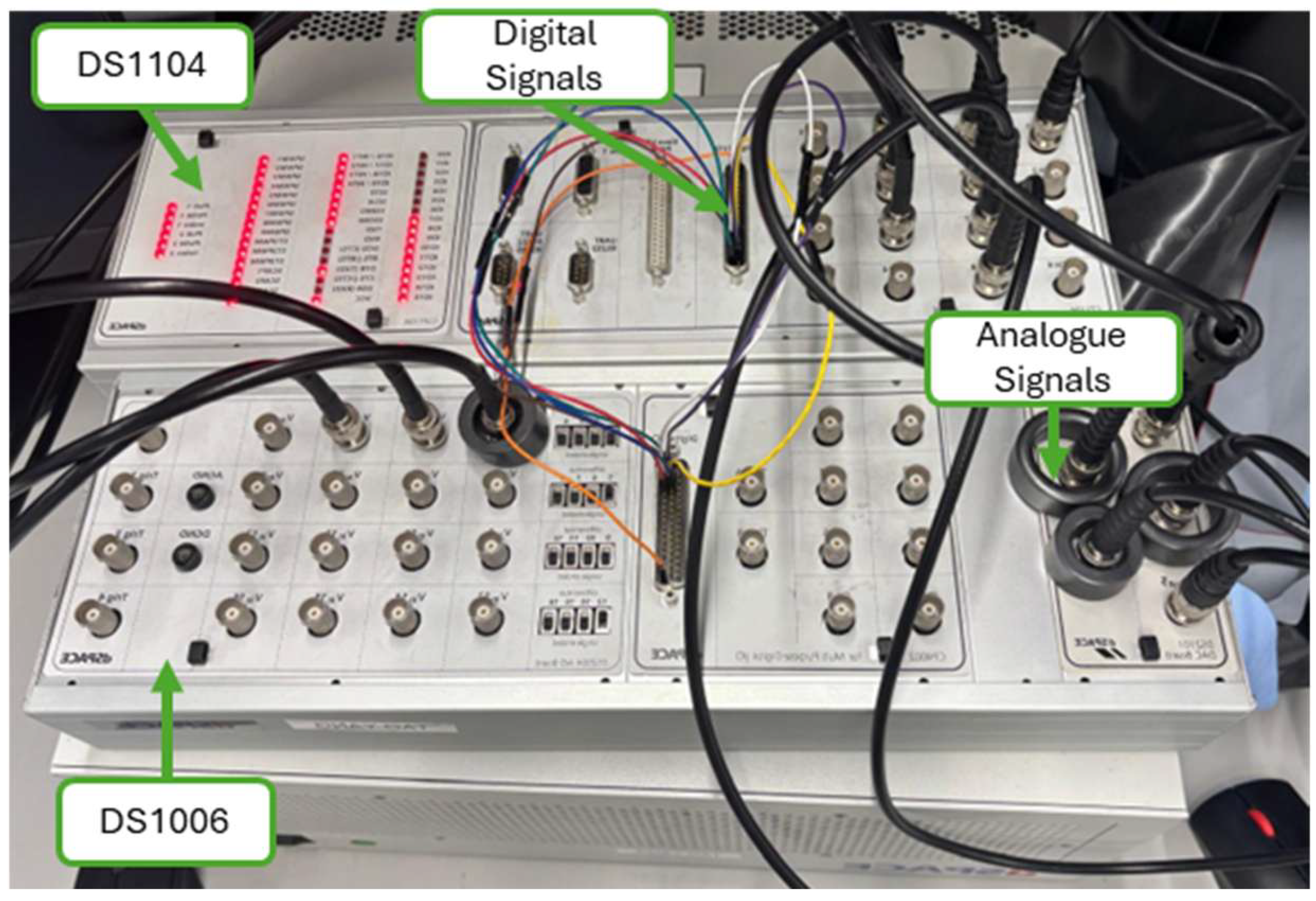
The validation of the EMS with integrated fuel consumption restrictions was implemented as a software-in-the-loop set-up in dSPACE, following the same approach as [34]. This set-up ensures real-time applicability of the enhanced EMS. This enables for the EMS controller to be separated from the EPS, consisting of the electrical power system and sizing models. The EPS and sizing models were implemented into dSPACE DS1006 (dSPACE SE & Co. KG, Paderborn, Germany) and the EMS, the controller into the smaller dSPACE DS1104 (dSPACE SE & Co. KG, Paderborn, Germany), with the two dSPACE’s connected through analogue and digital signals on the control boards, as shown in Figure 6.
Figure 6.
dSPACE validation set-up.
The use of software-in-the-loop for validation ensures that the EMS controller performs as expected. The control code is compiled into C for testing, and the change in software ensures that it behaves as expected across different solvers. The simulation step size is determined for accuracy and simulation speed to ensure that real-time simulation is feasible.
The dSPACE set-up is seen in Figure 7 and Figure 8. In Figure 7, on the left-hand side, the DS1006 is connected to a computer that runs the electrical power system modelling. On the right-hand side, the DS1104 is set up to run the control algorithm, which consists of the EMS. The connections between the two controller boards are seen in Figure 8, with both digital and analogue connections set up, with more wires connected than necessary for this model as it has been set up for larger-scale model testing as well.
Figure 7.
Lab bench validation set-up for SIL using dSPACE with interfacing control boards [34].
Figure 8.
Interfaces between DS1006 and DS1104 control boards [34].
The dSPACE set-up was used to obtain the results in the following section, which matched the results obtained through Simulink, and therefore, the EMS results are validated using software-in-the-loop.
5. Results
The EMS combined with FC sizing constraints has been tested for an aircraft EPS model, shown in Figure 1. A normalised mission profile, displayed in Figure 2, has been used to test the interaction between the EMS and sizing model for the FC. The main modelling parameters for this study are listed in Table 1, some of which were stated as the constraints for the model in Equation (14). The hydrogen slew rate limits how fast the system can react to changes, meaning that the battery is always required to react faster than the fuel cell. The hydrogen tank capacity and battery size were determined simultaneously to ensure that all mission requirements can be completed while maintaining a minimum battery SOC of 75%. Consequently, 75% of the battery capacity remains available as an energy reserve, which can be utilised to satisfy reserve and diversion requirements in the event that the hydrogen supply is depleted.
Table 1.
Key modelling parameters.
Typically, in electric vehicles, a fuel warning indicator will illuminate when 20% of fuel is remaining, depending on temperature and pressure [36]. Therefore, in this study, it is assumed that approximately 10% of the hydrogen must remain in the tank once it is considered depleted to ensure safety through pressurisation and temperature control in the fuel tank.
This aircraft and mission profile have been tested for an unconstrained EMS for hydrogen, and both the hydrogen limiting approaches are used to show the differences between the methods. Within both the constrained approaches, it is considered that there is no hydrogen remaining for the FC to operate when consumed hydrogen reaches 4.05 kg. This assumes that the original tank size is 4.50 kg, with 10% remaining in the tank after the completed depletion of hydrogen.
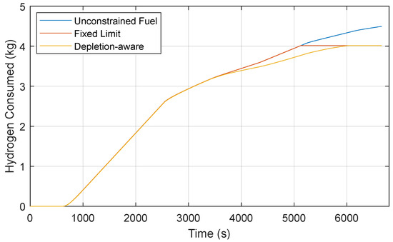
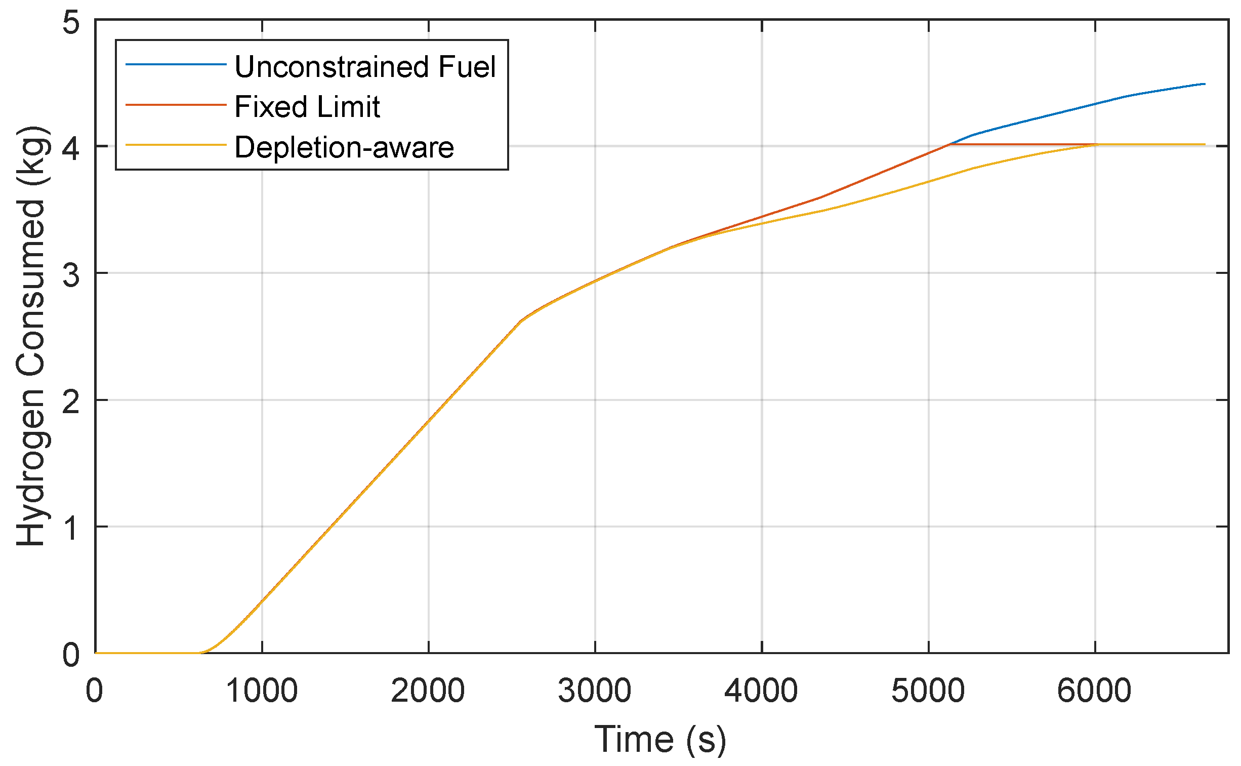
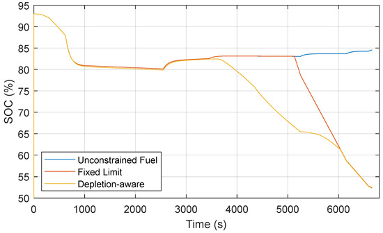
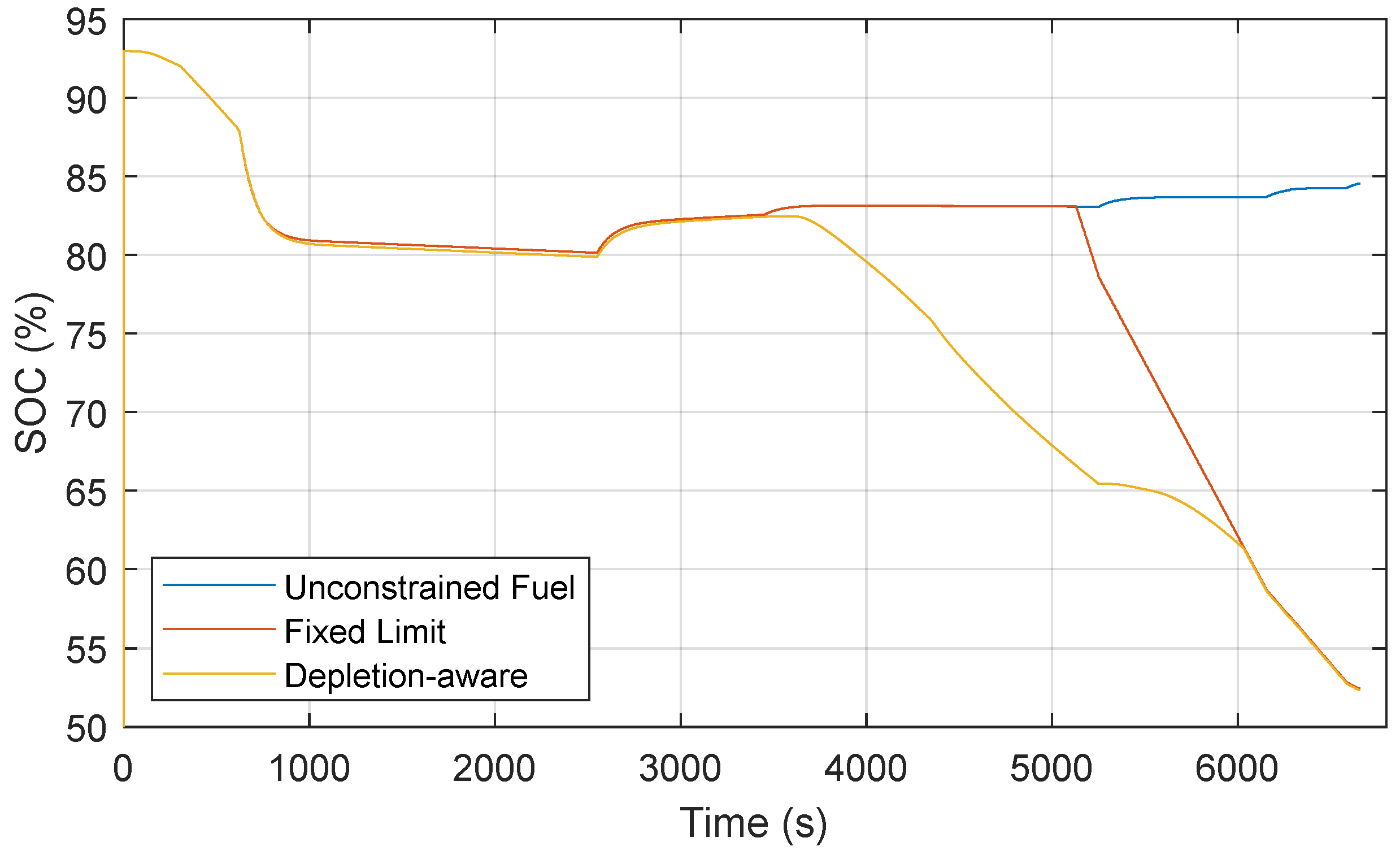
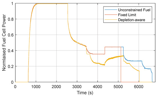
The approaches to limiting the hydrogen available are compared against the unconstrained hydrogen usage case, as shown in Figure 9 and Figure 10, for hydrogen consumption and battery SOC, respectively. This is followed by Figure 11, which shows the normalised FC power, which is a direct result of the energy management strategy power selection.
Figure 9.
Comparison of fuel cell hydrogen consumption.
Figure 10.
Comparison of battery SOC.
Figure 11.
Comparison of normalised fuel cell power output.
The noise in the FC power for the depletion-aware approach, as shown in Figure 11 around 4500 s, may cause slightly more energy usage than the smooth equivalent. This is due to changes in power demand from the EMS within the dSPACE set-up. These noises are not present in simulation results in Simulink, and refining of parameters and time steps may be able to minimise the noise in further studies. Reducing the step size can reduce some of this noise, but for the system to operate in real time, there is a minimum feasible step size that can be used for the model.
The unlimited fuel for the unconstrained method allows the aircraft to use more than the 4.50 kg designed to be on board the aircraft, and the 4.05 kg that is actually available to be used, as shown in Figure 9. Instead, this unconstrained approach requires an additional 0.60 kg, which equates to 14.81% above the available fuel to complete the mission. Therefore, it is an unrealistic scenario, as aircraft cannot refuel during a mission.
Within the fixed-limit approach, the FC operates normally, allowing the EMS to determine the power output. Although once this fixed hydrogen limit is reached, the FC cannot provide any more power, and the battery must immediately provide the remaining power to the system. This is shown in Figure 9, with the hydrogen consumed remaining at 4.05 kg, which is the total hydrogen available, and the battery SOC can be seen to decline at 5157 s.
The depletion-aware approach monitors the remaining hydrogen and adjusts the SOC and equivalence factor, if required. This enables greater use of the battery earlier, ensuring a smoother transition from FC and battery power to battery-only power. For example, within this study, it is implemented so that at 30% of the hydrogen remaining, the equivalence factor and battery SOC are lowered to an intermediate step. After the hydrogen remaining reaches below 20%, the equivalence factor and SOC are further reduced. Then, once it reaches 10% remaining, the hydrogen supply cannot be delivered as in the previous approach that applies a fixed limit to the hydrogen. This gradual decrease in SOC constraints, along with the equivalence factor, offers a smoother transition, as shown in Figure 9. However, for improved results, additional transition steps for equivalence factor and battery SOC decline at more than three hydrogen availability indicators should be explored in future studies. This aims to provide a constant gradual decline in hydrogen consumption and remove noticeable steps, allowing for improved battery lifespan, though a study exploring the impacts of these parameters was outside the scope of this paper.
Comparing the three approaches mentioned, the unconstrained fuel usage case uses approximately 14.81% more fuel than the available fuel within the fuel tank. Both the fixed-limit and depletion-aware cases respect this limit and turn the FC off once it reaches the limit of fuel availability. Furthermore, the unconstrained approach completes the mission with a battery SOC of 84.67%, whereas the constrained approaches have approximately the same battery SOC once the mission completes, with the fixed-limit and depletion-aware approaches reaching 52.45% and 52.35%, respectively. This means that for the additional 0.60 kg used by the unconstrained approach, the constrained approaches use an additional 32.3% battery SOC over the 6650 s mission profile.
Figure 11 provides a comparison between the output power from the FC for the three case studies. The constrained approach increases FC power as the power demand in the mission profile increases, the same as the unlimited fuel approach at approximately 4350 s. This shows that even though the fuel usage is being restricted, the EMS tries to optimise the system.
Table 2 highlights the final states of different parameters as a comparison of the three strategies. It explores the battery degradation costs for one mission, the estimated battery lifetime impact compared to the unconstrained approach, and the battery SOC throughput. The battery degradation cost is calculated using Equations (22) and (23) presented in [12,34], as mentioned in Section 3.3. The estimated lifetime impact of the battery shows that the fixed limit uses the battery 160% faster than the unconstrained approach for this mission, whereas the depletion-aware approach degrades the battery lifetime slightly less at 147%. The battery SOC throughput measures the continuous discharging and charging of the battery, with the higher value of the fixed-limit method highlighting more battery energy usage. A value of zero indicates no battery usage, and a value of two is equivalent to fully discharging and recharging the battery. Overall, this table shows that the unconstrained approach is best for battery degradation but lacks for over-usage of the hydrogen consumed. Therefore, the depletion-aware approach respects this constraint while using less battery energy than the fixed-limit approach.
Table 2.
Results summary of key performance indicators comparing the three approaches to hydrogen-constrained EMS.
With the constrained approaches, the limit to the hydrogen fuel means that an aircraft design can be created and tested within a simulation, ensuring that the desired mission profile can be achieved with the energy requirement on board. This limit to fuel respects the design of an aircraft and the inability to refuel during flight, similarly to the battery, which has fixed operation limits designed within the EMS. Further, the benefit of the depletion-aware approach over the fixed = limit one is that the FC can be ramped down over time, meaning there is no abrupt change between power sources when no fuel is remaining, and ensuring a smoother transition between systems during the FC switch off. As mentioned in Section 3.4.3, the depletion-aware approach reduces the stress on the FC, allowing the system to be both safer and more reliable as unforeseen circumstances arise from the lack of fuel available onboard the aircraft during a mission.
The purpose of this work was to establish a practical solution to limited fuel onboard aircraft, particularly when sizing hydrogen tanks for all-electric aircraft. This study demonstrated a methodology capable of being scaled up. This proposed strategy may be implemented onboard varying sizes of aircraft with multiple power sources, one of which contains fuel, to ensure that a sufficient amount remains throughout a mission duration. However, this was not included within the scope of this work. Instead, this paper compared three EMSs for constraining fuel, with the depletion-aware method being the proposed solution for sustainable aviation.
6. Conclusions
This paper presented an analytical model for sizing a complete FC system by extending a well-established stack sizing method and included hydrogen requirements. Building on this model, an energy management strategy was developed to actively constrain hydrogen use rather than treating the FC as an unlimited source. Three EMS approaches were examined to reflect different ways of handling hydrogen availability: an unconstrained approach, a fixed-limit method that enforces a hard shutdown when the tank is depleted, and a depletion-aware method that anticipates low-fuel conditions and increases battery usage to maintain a smoother transition between power sources.
The EMS approaches were implemented and evaluated through detailed MATLAB/Simulink simulations, with further verification carried out using software-in-the-loop testing on the dSPACE platform. The results show that incorporating a depletion-aware approach avoids abrupt FC shutdown, supporting a more controlled reduction in FC output with smoother battery–FC interaction. This means that hydrogen consumption is monitored and controlled throughout, and battery usage increases as the hydrogen stored is depleted. The unconstrained FC showed that the hydrogen consumed was 14.81% over the 4.05 kg of hydrogen available, whereas the fixed-limit and depletion-aware approaches respected the constraint. The depletion-aware approach also showed 13% less battery depletion when comparing against the fixed-limit approach, with the unconstrained approach as a reference for the best battery lifespan.
Overall, the work demonstrates practical EMS approaches for limiting onboard hydrogen while maintaining reliable power delivery, offering a scalable EMS framework suitable for future all-electric and hybrid-electric aircraft architectures.
Author Contributions
Conceptualization, A.R.E.W. and S.B.; methodology, A.R.E.W.; software, A.R.E.W. and S.Y.; validation, A.R.E.W. and S.Y.; formal analysis, A.R.E.W.; investigation, A.R.E.W.; resources, S.B.; data curation, A.R.E.W.; writing—original draft preparation, A.R.E.W.; writing—review and editing, S.S., S.B. and S.Y.; visualisation, A.R.E.W.; supervision, S.S., S.B. and S.Y.; project administration, S.B.; funding acquisition, S.B. All authors have read and agreed to the published version of the manuscript.
Funding
This research received no external funding.
Data Availability Statement
The data presented in this study are available on request from the corresponding author due to privacy.
Conflicts of Interest
The authors declare no conflicts of interest.
Abbreviations
The following abbreviations are used in this manuscript:
| EMS | Energy management strategy |
| ECMS | Equivalent consumption minimisation strategy |
| FC | Fuel Cell |
| SOC | State-of-charge |
References
- European Commission: Directorate-General for Research and Innovation and Directorate-General for Mobility and Transport. Flightpath 2050—Europe’s Vision for Aviation—Maintaining Global Leadership and Serving Society’s Needs; Publications Office of the European Union: Luxembourg, 2011. [Google Scholar] [CrossRef]
- Schlabe, D.; Lienig, J. Energy Management of Aircraft Electrical Systems—State of the Art and Further Directions. In Proceedings of the 2012 Electrical Systems for Aircraft, Railway and Ship Propulsion, Bologna, Italy, 16–18 October 2012. [Google Scholar] [CrossRef] [Scilit]
- Motapon, S.N.; Dessaint, L.A.; Al-Haddad, K. A Comparative Study of Energy Management Schemes for a Fuel-Cell Hybrid Emergency Power System of More-Electric Aircraft. IEEE Trans. Ind. Electron. 2014, 61, 1320–1334. [Google Scholar] [CrossRef] [Scilit]
- Silvas, E.; Hofman, T.; Murgovski, N.; Etman, L.F.P.; Steinbuch, M. Review of Optimization Strategies for System-Level Design in Hybrid Electric Vehicles. IEEE Trans. Veh. Technol. 2017, 66, 57–70. [Google Scholar] [CrossRef] [Scilit]
- Xu, W.; Huang, H.; Wang, C.; Xia, S.; Gao, X. A Comparative Study of Energy Management Strategies for Battery-Ultracapacitor Electric Vehicles Based on Different Deep Reinforcement Learning Methods. Energies 2025, 18, 1280. [Google Scholar] [CrossRef] [Scilit]
- Tella, V.C.; Alzayed, M.; Chaoui, H. A Comprehensive Review of Energy Management Strategies in Hybrid Electric Vehicles: Comparative Analysis and Challenges. IEEE Access 2024, 12, 181858–181878. [Google Scholar] [CrossRef] [Scilit]
- Sunny, M.R.; Kabir, M.A.; Naheen, I.T.; Ahad, M.T. Residential Energy Management: A Machine Learning Perspective. In Proceedings of the 2020 IEEE Green Technologies Conference (GreenTech), Oklahoma City, OK, USA, 1–3 April 2020; pp. 229–234. [Google Scholar]
- Xi, Z.; Wu, D.; Ni, W.; Ma, X. Energy-Optimized Trajectory Planning for Solar-Powered Aircraft in a Wind Field Using Reinforcement Learning. IEEE Access 2022, 10, 87715–87732. [Google Scholar] [CrossRef] [Scilit]
- Li, Y.; Guo, Y.; Zhang, Y. Equivalent Consumption Minimization Energy Management Strategy Based on Frequency Decoupling for Unmanned Surface Vehicle. In Proceedings of the 2023 3rd International Conference on Energy, Power and Electrical Engineering (EPEE), Wuhan, China, 15–17 September 2023; pp. 1261–1267. [Google Scholar]
- Torreglosa, J.P.; Jurado, F.; García, P.; Fernández, L.M. Hybrid fuel cell and battery tramway control based on an equivalent consumption minimization strategy. Control Eng. Pract. 2011, 19, 1182–1194. [Google Scholar] [CrossRef] [Scilit]
- Yuan, H.-B.; Zou, W.-J.; Jung, S.; Kim, Y.-B. Optimized rule-based energy management for a polymer electrolyte membrane fuel cell/battery hybrid power system using a genetic algorithm. Int. J. Hydrogen Energy 2022, 47, 7932–7948. [Google Scholar] [CrossRef] [Scilit]
- Li, S.; Zhao, P.; Gu, C.; Bu, S.; Pei, X.; Zeng, X.; Li, J.; Cheng, S. Hybrid Power System Topology and Energy Management Scheme Design for Hydrogen-Powered Aircraft. IEEE Trans. Smart Grid 2024, 15, 1201–1212. [Google Scholar] [CrossRef] [Scilit]
- Salem, M.; Elnaggar, M.; Saad, M.S.; Fattah, H.A.A. Energy Management System for Fuel Cell-Battery Vehicles Using Multi objective Online Optimization. IEEE Access 2022, 10, 40629–40641. [Google Scholar] [CrossRef] [Scilit]
- Kaya, K.; Dömez, O.; Özece, B. Towards Efficient and Sustainable Transportation: A Novel Energy Management Strategy for Multi-Stack Fuel Cell Electric Vehicles. In Proceedings of the 2024 IEEE 100th Vehicular Technology Conference (VTC2024-Fall), Washington, DC, USA, 7–10 October 2024; pp. 1–5. [Google Scholar]
- Zhang, Y.; Li, Q.; Wen, C.; Liu, M.; Yang, X.; Xu, H.; Li, J. Predictive equivalent consumption minimization strategy based on driving pattern personalized reconstruction. Appl. Energy 2024, 367, 123424. [Google Scholar] [CrossRef] [Scilit]
- Paganelli, G.; Delprat, S.; Guerra, T.M.; Rimaux, J.; Santin, J.J. Equivalent consumption minimization strategy for parallel hybrid powertrains. In Proceedings of the Vehicular Technology Conference. IEEE 55th Vehicular Technology Conference. VTC Spring 2002 (Cat. No.02CH37367), Birmingham, AL, USA, 6–9 May 2002; Volume 2074, pp. 2076–2081. [Google Scholar]
- Chai, H.; Zhao, X.; Yu, Q.; Wang, S.; Han, Q.; Zheng, Z. Adaptive equivalent consumption minimization strategy based on road grade estimation for a plug-in hybrid electric truck. J. Energy Storage 2023, 70, 108035. [Google Scholar] [CrossRef] [Scilit]
- Wise, A.; Sumsurooah, S.; Hebala, O.; Bozhko, S.; Yeoh, S. Adaptive-ECMS for electric aviation: Ensuring safety through failure-responsive energy management. IET Conf. Proc. 2025, 2025, 127–132. [Google Scholar] [CrossRef] [Scilit]
- Delprat, S.; Boukhari, M.R. Reducing the Computation Effort of a Hybrid Vehicle Predictive Energy Management Strategy. IEEE Trans. Veh. Technol. 2021, 70, 6500–6513. [Google Scholar] [CrossRef] [Scilit]
- Song, K.; Huang, X.; Xu, H.; Sun, H.; Chen, Y.; Huang, D. Model predictive control energy management strategy integrating long short-term memory and dynamic programming for fuel cell vehicles. Int. J. Hydrogen Energy 2024, 56, 1235–1248. [Google Scholar] [CrossRef] [Scilit]
- Doff-Sotta, M.; Cannon, M.; Bacic, M. Predictive Energy Management for Hybrid Electric Aircraft Propulsion Systems. IEEE Trans. Control Syst. Technol. 2023, 31, 602–614. [Google Scholar] [CrossRef] [Scilit]
- Wise, A.R.E.; Sumsurooah, S.; Hebala, O.M.; Bozhko, S.; Yeoh, S.; Manrique, C. Modelling of Aircraft Electric Propulsion System with Failure-Response Energy Management. In Proceedings of the 2025 IEEE International Conference on Environment and Electrical Engineering and 2025 IEEE Industrial and Commercial Power Systems Europe (EEEIC/I&CPS Europe), Lisbon, Portugal, 15–18 July 2025; pp. 1–6. [Google Scholar]
- Wise, A.; Bozhko, S.; Yeoh, S.; Sumsurooah, S.; Manrique, C. Dual stage battery sizing and performance assessment on-board hybrid electric aircraft. In Proceedings of the 34th Congress of the International Council of the Aeronautical Sciences, Florence, Italy, 9–13 September 2024; p. 10. [Google Scholar]
- Spiegel, C. PEM Fuel Cell Modeling and Simulation Using MATLAB, 1st ed.; Elsevier Science & Technology: Amsterdam, The Netherlands, 2008. [Google Scholar] [CrossRef] [Scilit]
- Karami, N.; Outbib, R.; Moubayed, N. Fuel flow control of a PEM Fuel cell with MPPT. In Proceedings of the 2012 IEEE International Symposium on Intelligent Control, Dubrovnik, Croatia, 3–5 October 2012; pp. 289–294. [Google Scholar] [CrossRef] [Scilit]
- Dicks, A.L.; Rand, D.A.J. Fuel Cell Systems Explained, 3rd ed.; Wiley: Hoboken, NJ, USA, 2018. [Google Scholar]
- Gou, B.; Na, W.K.; Diong, B. Fuel Cells: Dynamic Modeling and Control with Power Electronics Applications, 2nd ed.; Power Electronics and Applications Series; CRC Press: Boca Raton, FL, USA, 2017. [Google Scholar]
- Baudy, M.; Jaafar, A.; Turpin, C.; Abbou, S.; Rigal, S. Experimental study of the potential degradation due to the polarization curve of a high temperature proton exchange membrane fuel cell. Int. J. Hydrogen Energy 2023, 48, 20945–20956. [Google Scholar] [CrossRef] [Scilit]
- Huang, X.; Zhang, Z.; Jiang, J. Fuel Cell Technology for Distributed Generation: An Overview. In Proceedings of the 2006 IEEE International Symposium on Industrial Electronics, Montreal, QC, Canada, 9–13 July 2006; Volum 2, pp. 1613–1618. [Google Scholar]
- Zhao, Y.; Wang, Q.; Xu, L.; Hu, Z.; Jia, X.; Qin, Z.; Li, J.; Ouyang, M. Characteristic Analysis of Fuel Cell Decay Based on Actual Vehicle Operating Conditions. In Proceedings of the 2021 IEEE 4th International Electrical and Energy Conference (CIEEC), Wuhan, China, 28–30 May 2021; pp. 1–5. [Google Scholar]
- Arif, M.; Cheung, S.C.P.; Andrews, J. A systematic approach for matching simulated and experimental polarization curves for a PEM fuel cell. Int. J. Hydrogen Energy 2020, 45, 2206–2223. [Google Scholar] [CrossRef] [Scilit]
- García, P.; Torreglosa, J.P.; Fernández, L.M.; Jurado, F. Viability study of a FC-battery-SC tramway controlled by equivalent consumption minimization strategy. Int. J. Hydrogen Energy 2012, 37, 9368–9382. [Google Scholar] [CrossRef] [Scilit]
- Jiao, K.; Wang, B.; Du, Q.; Wang, Y.; Zhang, G.; Yang, Z.; Deng, H.; Xie, X. Chapter 3—Experimental characterization and diagnostics. In Water and Thermal Management of Proton Exchange Membrane Fuel Cells; Elsevier: Amsterdam, The Netherlands, 2021; pp. 67–120. [Google Scholar] [CrossRef] [Scilit]
- Wise, A.R.E.; Sumsurooah, S.; Yeoh, S.; Bozhko, S.; Hebala, O. Extended Comparative Analysis of Aircraft Energy Management Strategies for Improvements in Energy Expenditure, Hydrogen Savings, and Battery Lifecycle Assessment. Aerospace 2026, 13, 251. [Google Scholar] [CrossRef] [Scilit]
- Li, R.; Zhou, J.; Yao, N.; Zhou, Y.; Lin, W.; Xu, Z.; Su, J.; Shi, L.; Ma, T. Impact of shutdown operations on the recovery of reversible degradation in proton exchange membrane fuel cells. eTransportation 2025, 26, 100468. [Google Scholar] [CrossRef] [Scilit]
- de Miguel, N.; Acosta, B.; Moretto, P.; Cebolla, R.O. The effect of defueling rate on the temperature evolution of on-board hydrogen tanks. Int. J. Hydrogen Energy 2015, 40, 14768–14774. [Google Scholar] [CrossRef] [Scilit]

Disclaimer/Publisher’s Note: The statements, opinions and data contained in all publications are solely those of the individual author(s) and contributor(s) and not of MDPI and/or the editor(s). MDPI and/or the editor(s) disclaim responsibility for any injury to people or property resulting from any ideas, methods, instructions or products referred to in the content. |
© 2026 by the authors. Licensee MDPI, Basel, Switzerland. This article is an open access article distributed under the terms and conditions of the Creative Commons Attribution (CC BY) license.