


Abstract
Space robots must be designed with a large operating radius and lightweight components (flexible joints and flexible links). The integration of flexible components inevitably affects the control accuracy of the robot. When modeling the link deformation of the space robot, the idealized description method has the problem of incomplete accuracy in link deformation due to the coupling effects of the non-fixed base, flexible joints, and changes in control parameters. To address this challenge and improve the accuracy of robot modeling, this study proposes a dynamic coupling analysis method for the link deformation of space robots based on time-domain response. The double finite difference method is adopted to calculate the time-domain response of link deformation. On this basis, using the local linear operator method, the modal information of the deformed links is extracted. This method systematically quantifies the individual and interactive effects of the robot’s base motion, joint flexibility, and control parameters on link deformation. This work not only lays a theoretical foundation for the accurate dynamic modeling of space robots but also provides practical insights for optimizing their structural design. Ultimately, it contributes to the development of more reliable and high-performance space robot systems.
1. Introduction
Space robots can assist astronauts in accomplishing tasks such as spacecraft docking, maintenance, and capture [1,2]. As spacecraft develop toward the trends of large size, light weight, and high precision, space robots are required to feature low stiffness, large working radius, and integrated actuation. These requirements lead to the deformation of the robot links. The joint structure incorporates harmonic reducers, elastic dampers, and flexible sensors, which endow the joints with flexibility. Consequently, space robots are classified as a type of multi-flexible special-purpose robot [3]. The flexible components significantly complicate the modeling and control of space robots [4,5]. The description of the flexibility of these components will greatly affect the modeling accuracy. Therefore, to achieve better control of flexible space robots, a more accurate modeling and analysis model is essential.
To establish an accurate dynamic model for a flexible-link robot, it is first essential to describe and analyze the deformation of its links in a discrete manner. For links with regular geometric shapes, the Euler–Bernoulli beam is commonly employed as a standard beam model. The Assumed Modes Method (AMM) is typically used to describe such deformations; however, it neglects the shear effect [6]. In contrast, the finite element method (FEM) is highly effective in characterizing the deformation of irregularly shaped links—and additionally, it can account for the shear effect [7]. Beyond the two aforementioned methods for describing the deformation of flexible links, there exist other approaches, including the Modal Synthesis Method (MSM), Lumped Parameter Method (LPM), Finite Segment Method (FSM), and B-spline Interpolation (BSI) [8,9]. When these methods are applied to flexible robot modeling, their boundary conditions still need to be evaluated; nevertheless, over-idealization of boundary conditions may lead to deviations between the model and the actual system [10]. Therefore, the modal parameters of the system must be determined based on the deformation response of the flexible links under actual operating conditions. Hao et al. [11] presented an assumed mode analysis-based manipulator modeling method adopting fixed-load boundary conditions for links. The ideal constraints differ greatly from practical conditions, causing low modal extraction accuracy. Zhou et al. [12] detected manipulator link deformation through experiments, yet the method demands massive repeated tests and ignores effects of joints and base platform, leading to obvious deviations. Kumar et al. [13] established a mobile manipulator dynamic model via the extended Hamilton principle with joint–rotor inertia coupling, but neglected the mobile platform’s impact on arm deformation. Summarizing the literature [10,11,12,13], it is evident that under idealized assumptions, the deformation of flexible robotic arms during multi-modal information acquisition deviates significantly from actual descriptions. This paper treats space robots as mobile flexible robotic arms, comprehensively considering the effects of the base, flexible joints, and geometric shape on the deformation of flexible linkages. This approach ensures boundary conditions better align with real-world operational scenarios, enabling more accurate extraction of modal information from the time-domain response of link deformation. This approach not only provides a theoretical foundation for dynamic modeling of flexible space robots but also enables analysis of link deformation patterns under various influencing factors.
As summarized above, the process of constructing a dynamic model for flexible robots involves two key steps: First, identifying, evaluating, and extracting modal information related to the deformation of flexible links is fundamental to ensuring the model accurately reflects flexible characteristics. Second, combining the physical parameters and structural features of the manipulator is necessary to further extract additional data required for predicting the robot’s dynamic behavior. Based on this process, various modeling techniques have been developed and applied to the dynamics of flexible link robots. Examples include the Newton–Euler method using the Modal Superposition Method (MSM), the Lagrangian method employing the Absolute Node Coordinate Method (AMM), and the Lagrangian method utilizing the finite element method (FEM) [14,15]. Kraïem et al. [16] used the AMM and Newton–Euler methods to construct a single-joint flexible robot dynamics model. While this model can rapidly capture changes in the robot’s motion state, it exhibits significant shortcomings: the end-effector positioning error of the flexible manipulator remains relatively high, primarily due to insufficient description accuracy of the flexible link. Masoumi et al. [17] established a dynamic model for flexible robots based on the Automatic Market Maker (AMM) and Lagrange methods. While this model incorporates load effects as an advantage, it fails to account for joint structural damping and load interactions within the deformation boundary conditions of its flexible linkages. Consequently, the model’s description of flexible components deviates from actual operating conditions. Shang et al. [18] proposed a robotic dynamics model applicable to complex-shaped link structures and employed finite element dynamics analysis to describe link deformation. This approach suffers from two limitations: first, an irreconcilable trade-off exists between computational efficiency and analytical accuracy; second, its applicability is restricted, rendering it unsuitable for modeling scenarios involving multi-link flexible robots. Ouyang et al. [19] established a 2DOF flexible robot for modeling research, incorporating matching boundary conditions for link bending deformation into the model. However, this model does not account for interactions between multiple links in the consideration of link deformation, presenting certain limitations. Liu et al. [20] employed the Absolute Node Coordinate Method to construct a nonlinear model of the flexible mechanical system (SLFM). However, their study did not fully account for the coupling effects between flexible deformation and rigid motion, a factor that may impact the accuracy of the dynamic analysis. Summarizing and analyzing the references [16,17,18,19,20], based on current research focuses, existing studies on dynamic modeling of flexible robotic arms predominantly concentrate on deformation description and modeling method optimization for single flexible links (e.g., References [16,17]). However, research on modeling multi-flexible-link systems, particularly in boundary condition design and coordinated deformation description under multi-link coupling scenarios, remains significantly underdeveloped (e.g., References [18,19]). This paper comprehensively considers multiple factors—mobile platforms, joint flexibility, and adjacent joint characteristics—to modify the deformation boundaries of flexible linkages. This approach enables more accurate descriptions of the deformation in multi-flexible robotic arms, thereby enhancing the precision of dynamic modeling for flexible robotic systems.
Based on the above research, dynamic modeling of flexible robots requires the incorporation of flexible link deformation with high-fidelity characterization, which is a crucial prerequisite for guaranteeing modeling accuracy. Deformation acquisition for flexible manipulators mainly relies on theoretical modeling and experimental testing, yet both techniques suffer from inherent limitations. The analytical modal method (AMM) adopts idealized hypotheses and continuous deformation functions to characterize structural deformation, which inevitably produces deviations from the practical deformation of flexible links under real working scenarios. Alternatively, the finite element method (EFM) demands linearization and fine discretization of flexible structures, leading to intensive computational costs. Moreover, conventional simulation tools fail to fully capture the complex dynamic behaviors of spatial flexible robots, further compromising the modeling reliability of simulation-based approaches. In terms of experimental investigation, the extreme complexity of space environments hinders the replication of in-orbit operating conditions, restricting the direct applicability of ground-based experimental conclusions to space flexible robot systems. In addition, high-precision dynamic measurement instruments can only acquire one-dimensional deformation information, which substantially limits the comprehensiveness and effectiveness of experimental testing. To address the aforementioned deficiencies, this work considers the multi-factor coupling effects on flexible link deformation and develops a novel deformation description method for spatial flexible robot components using the time-domain response data of flexible manipulators.
In this paper, a dynamic coupling analysis model of robot link deformation is constructed with a flexible space robot as the research object. The paper is organized as follows: Part one, introduction, Part two, problem description; Part three, complex dynamics of link deformation of flexible space robot; and analysis of link deformation based on control characteristics; Part four, identification of link modes based on dynamic time-domain response; Part five, numerical simulation validation of the model; and Part six, analytical summary of this paper.
2. Problem Description
Recapitulating earlier studies on flexible robotics, it is evident that, in addition to its extensive range of rigid body motions, the modeling of a general flexible robot needs account for the deformation of the flexible pieces attached to it [21]. Regarding the issue of describing the deformation of flexible links, the majority of research that has been done thus far has used cantilever beams as standard beams, whose boundaries consider the fixed–freedom combination boundary as the ideal boundary condition [22,23]. The AMM is used to describe the deformation of these links. This is not at all like the description of link deformation found in actual space robots that operate [24].
- The space robot base and the manipulator are coupled to each other, and their motion affects the deformation of the manipulator link.
- A flexible drive mechanism is designed into the joint structure of the manipulator, which causes significant torsional deformation of the joint and a coupling effect between it and the manipulator [25].
- When a space robot performs trajectory tracking control, the drive torque will cause its actual tracking trajectory to be continuously adjusted in a closed loop around the predetermined trajectory, which will lead to the inevitable influence of the control parameters on the deformation of the manipulator link [26].
Therefore, to establish a more accurate dynamic model of the flexible space robot, this paper comprehensively considers factors such as robot base, joint flexibility damping and control parameters, and analyzes its link boundaries and deformation characteristics.
3. Complex Dynamic Analysis of Link Deformation
3.1. Dynamic Coupled Analytical Model of Link Deformation
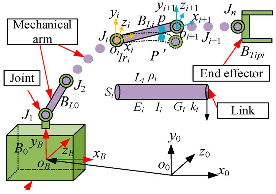
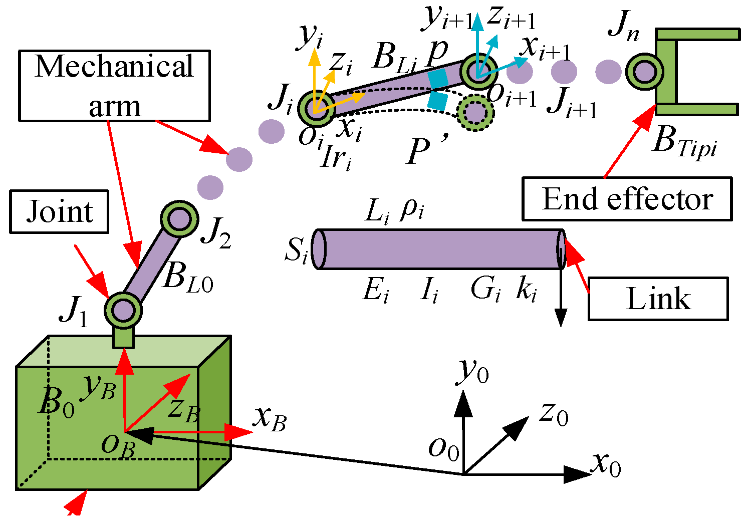
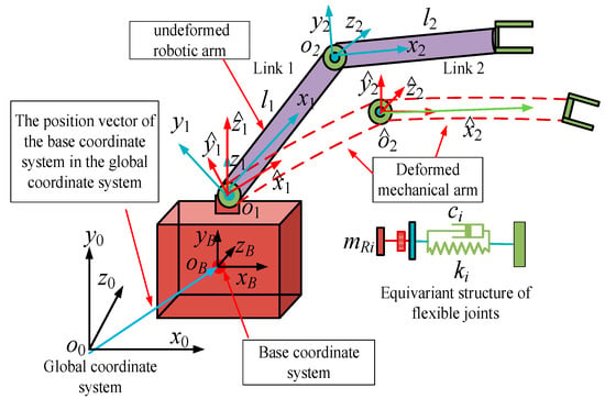
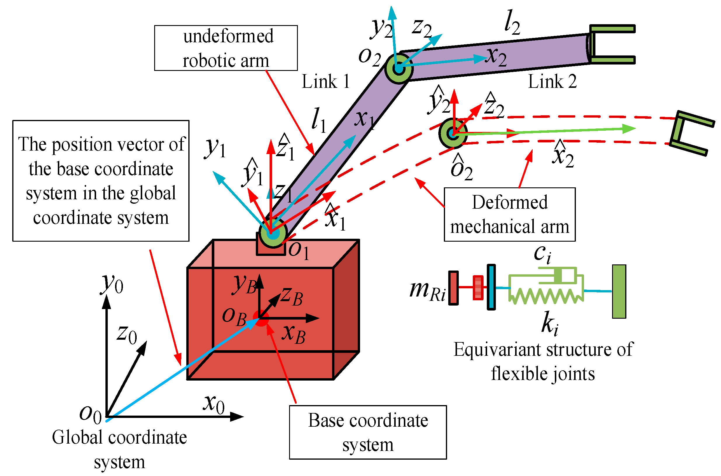
In this paper, flexible space robots are regarded as robotic arm systems mounted on mobile platforms featuring FJFL coupled structures, as shown in Figure 1. The equilibrium equation for the deformation of flexible linkages is established based on the principle of force and moment equilibrium [27]. Considering the influence of the base, joint flexibility, damping, and tip load on the link deformation, the link boundaries and the adjacent boundaries in its multi-link manipulator are adjusted to more accurately calculate the time-domain response of the link deformation.
Figure 1.
The simplified structure model of the space robot.
In Figure 1, o0-x0y0z0 is the global coordinate system, and oB-xByBzB is the center-of-mass coordinate system of the robot base. The link structure is an isotropic structure with uniform mass. li is the length and ρi is the density, where i = 1,… n, and n is the number of links. Each link end has an equivalent rigid load of equivalent mass Mi and equivalent inertia Ji; Iri is the motor moment of inertia. When i = 1,… n − 1 indicates that the oi drive motor exists at the joint. oi-xiyizi is the coordinate system fixed to the end of the i-1 link, the coordinate system zi axis is coaxial with the motor’s rotational axis, xi is the axial direction of the link, and according to the criterion of the right-handed coordinate system, yi is determined. If the motor rotor, reducer and hub are used as a coaxial mounting device, the part is a flexible joint device, which is connected to the beginning of the link by a hub joint device. oi+1-xi+1yi+1zi+1 is the coordinate system of the connection between the joint and the link, the zi+1 axis is coincident with the center axis of the joint, and xi+1 points to the direction of the link axis. By the same token, the direction of yi+1 is determined. p is the position point on the central axis of the link before deformation from oi point x, and p′ is the position point after deformation relative to point p on the rigid link. When analyzing the flexible link deformation, the following assumptions need to be made:
- (1)
- The manipulator link is differentiated into a number of finite segments for study: lE = l/Nl, lE is the length of the finite segment, and Nl is the number of segments. The link deformation of the finite segment can be expressed by the elastic deformation of the end, and a flexible connection exists between two adjacent finite segments.
- (2)
- Although the ratio of link length to cross-sectional dimension is large, which is in line with Euler–Bernoulli Beam Theory (EBBT), the model generally does not consider the effects of torsional deformation and shear deformation, and the deformation of the manipulator link in actual operation and control needs to be investigated in terms of its three-dimensional variables. Therefore, this subsection analyzes the three-dimensional flexible deformation of the manipulator link based on Timoshenko Beam Theory (TBT).
- (3)
- Under the small-deformation assumption of the flexible link, the deformation displacement of any point pi on the i-th link in the reference system oi-xiyizi can be expressed as [ui, vi, wi]T, and ui(xi, t), vi(xi, t) and wi(xi, t) denote the axial, longitudinal, and transverse displacements experienced by the point pi, respectively.
- (4)
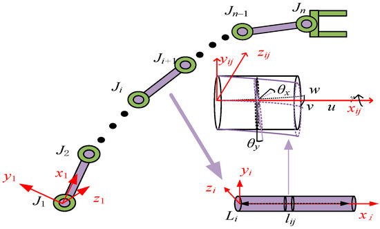
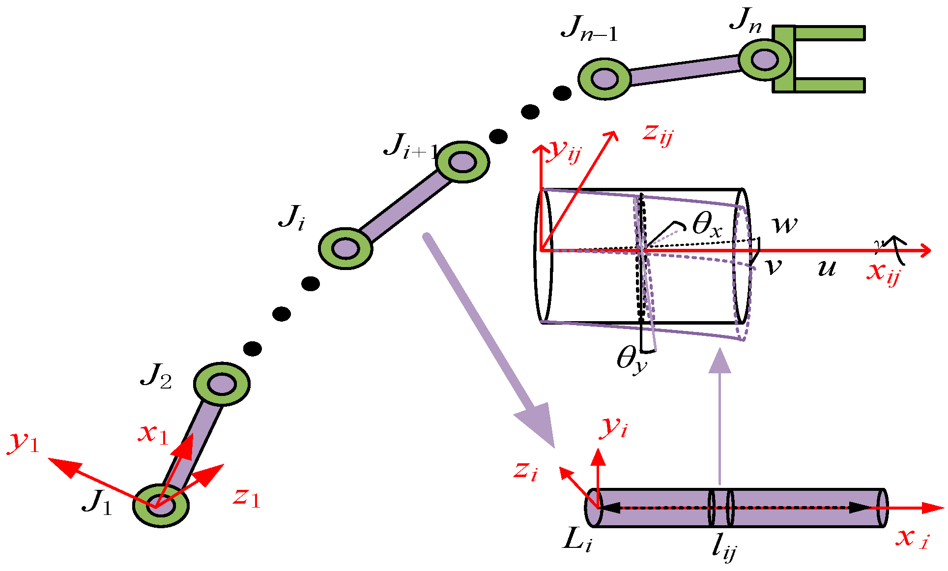
- To expedite the analysis of link deformation, the link is divided into finite segments, denoted as L/N, as shown in Figure 2. However, the number of finite segments is significantly smaller than the number of finite elements to ensure computational efficiency. The connecting boundaries between finite segments can be regarded as passive rigid joints without driving forces.Figure 2. Force analysis of flexible link.
In Figure 2, i is the i-th link, j is the j-th finite segment on the link, u is the axial displacement in the x-direction, v is the lateral displacement in the y-direction, w is the lateral displacement in the y-direction, γ is the torsion angle of the cross-section about the x-axis, and θx and θy are the angles of rotation of the cross-section about the x-axis and y-axis, respectively.
Based on the description of the manipulator modeling in step (1) above, the manipulator link is discretized. Based on D’Alembert’s principle, the dynamic equilibrium equations of the link can be obtained as follows.
where (a) is the displacement equation of the link in the x-direction, (b) is the displacement equation of the link in the y-direction and z-direction, (c) is the rotation equation of the link about the y- and z-pairs, and (d) is the torsion equation of the link about the x-pair. Eij is the elastic modulus, Sij is the link’s cross-sectional area, ρij is material density, Iz and Iy are the moment of inertia, kz and kz are shear correction coefficients., Gij is the shear modulus, Ip is the polar moment of inertia of the cross-section, Ip = Iy + Iz, ax,I, ay,I and az,i are the components of the link element’s absolute acceleration vector, respectively.
By combining (1b) and (1c), the sectional rotation is eliminated. The deflection equations for v and w are obtained. The deformation equations for any segment of the link are further derived.
Every differential finite element in the manipulator’s link is in a state of compound motion. ai(xi) [8] is as follows:
where , and are the vectors of translational acceleration, Coriolis acceleration and relative acceleration of the link’s differential element, respectively.
The following is the analysis and solution of the three accelerations respectively:
where ai(oi) is the absolute acceleration vector of point oi, ωi(oi) + [γ, θy, θz], and and are the angular velocity vectors and angular acceleration vectors of the movable coordinate oi-xiyizi with respect to the reference coordinate o-x0y0z, respectively. includes the cross-sectional angles θy, θz and the torsion angle γ, .
By the angular acceleration description [21], and in any link differential element are obtained.
Using Equations (3)–(5), Equation (2) can be further derived as follows:
where Nyij is and Nyij is .
When setting the boundary conditions of the system in Equation (6), their total order must be considered. In addition, the equations contain, besides the unknown variables ui(xi, t), vi(xi, t), wi(xi, t) and γi(xi, t), six unknown functions aj,i(oj) and describing the acceleration of the origin oi in the movable coordinate system oi-xiyizi with (j = x, y, z) and its angular acceleration. Therefore, to solve the system in Equation (6), it is necessary to establish 18 connection equations of the i-1st link and the i-th link.
3.2. Boundary Conditions and Initial Conditions
To affect the universal setting of two adjacent links in a multi-link, the i-1st link and the i-th link of the adjacent links are connected by a rotating hinge with the center axis of the rotating hinge coinciding with the joint coordinate axis oizi. Since the system oi-xiyizi is rigidly connected to the xi = 0 end of the i-th link, the deformation of the link at xi = 0 with its deformation velocity initial condition is:
When the i-th link is a hub joint with the initial end of the i+1st link, the modulus of the reaction equation at the link joint is equal to the modulus of the equation in the opposite direction of its vector. The reaction vector component R of the end xi = li of the i-th link is as follows:
All elements of Equation (9) are projected onto the axes of the oi-xiyizi reference system, and they are simplified as:
where is the transfer matrix between the coordinate system oi-xixizi and the two unit vectors in the coordinate system oi+1-xi+1yi+1zi+1, Jii+1 = tr(JTiJi+1), Ji= tr([cos(X, xi), cos(Y, yi), cos(Z, zi)], tr(*) is the trace of the matrix.
The force vector relationship at the i-th joint:
According to the decomposition of Equation (9), Equation (11) is similarly transformed into the following form:
If the matrix is designed in the joint axis direction, which in turn leads to Equation (14) from the system (12).
where ki is the joint equivalent stiffness, ci is the joint equivalent damping, and Jri is the joint moment of inertia.
Absolute acceleration vector relationship between two adjacent links at the i-th joint structure is obtained. By the similar decomposition principle of Equation (9), the corresponding decomposition projection of Equation (13) is obtained:
Using relations (3) to (5), Equation (13) is simplified to the following equation:
According to the relationship between the angular acceleration of the coordinate system oi+1-xi+1yi+1zi+1 and oi-xiyizi, the acceleration of the manipulator joints can be obtained:
where H(θ) is the joint rotation matrix between two adjacent links.
Using the form of explicit equality, Equation (14) can be expressed as Equation (16):
where is the angle of rotation of the z-axis in the joint coordinate system.
If the angular velocity projection vectors of joints Oi at , , are known, ωi(xi)|xi=li is the angular velocity vector at the end of the i-th link; based on the superposition theorem of robots’ angular velocities in compound motion [16], Equation (20) is further derived. Based on the projection vectors in Equation (9) at , , , Equation (21) is obtained:
Taking the derivative of Equation (21) with respect to time t, Equation (22) can be derived
The base platform motion and the end loads are the boundary conditions for the first link’s initial end and the last link’s tip, respectively. When the hinge at the end of the i-th link xi = li is a rigid connection, its end load can be written in the form of a differential equation for the motion of a free rigid body [21].
where mL is the mass of the finite unit, and ax,i+1, ay,i+1 and az,i+1 are the projections of the object’s center of mass oi+1 acceleration on the axes of the local coordinate oi+1-xi+1yi+1zi+1, which is rigidly connected to the body. Rx,i+1, Ry,i+1 and Rz,i+1 are the reaction vector components of the end xi = li of the i-th link on the coordinate oi+1-xi+1yi+1zi+1.
where IxL, IyL and IxL are the spindle moments of inertia, respectively, ωx,i+1, ωy,i+1 and ωz,i+1 are the angular velocities of the object in the main axis of the system coordinate system oi+1xi+1yi+1zi+1 respectively, and Mx,i+1, My,i+1 and Mx,i+1 are the reaction moments at the end of the i-th link in the coordinate system oi+1xi+1yi+1zi+1.
The initial state variable of mechanical system pose and pose velocity at t = 0:
where Equation (21) is the initial condition for the system (6) (Equations (11), (13) and (17)).
3.3. Double Finite Difference Method of the Manipulator Link Coupling Deformation
In this paper, Equation (6) is a system of high-order nonlinear equations. To efficiently solve this system, this paper proposes a dual finite difference method based on variable parallel computation. This method employs spatial and temporal discretization, utilizing high-order central differences and high-order temporal differences to solve the higher-order differential equations presented herein. The solution procedure remains identical for all variables u, v, w, and γ. Taking the second equation in Equation (6) as an example, we proceed with its solution. First, the equation is analyzed as follows:
- According to Equation (6), this expression involves second-order spatial derivatives and fourth-order spatial derivatives (∂2u/∂x2, ∂2v/∂x2, ∂2w/∂x2, ∂2γ/∂x2) as well as coupling terms (∂4v/∂x4, ∂4w/∂x4), and coupling terms ∂4v/∂x2∂t2 and ∂4w/∂x2∂t2. Therefore, using a fourth-order finite difference scheme, Equation (6b) is discretized.
- This equation is discretized spatially in one dimension, specifically along the x-direction. The length of the limited section is le = Δx, and the discrete point is xj = j·Δx, (j = 1,2, …N).
- In terms of time, the time interval t is divided into M time steps, each with a step size of Δt. Time point is tk = k·Δt, (k = 1,2, …N).
- In summary, (2) and (3) are discrete, and the variables u, v, w and γ can be discretized as f(xj, tk). Taking v as an example, , .
In Equation (6), ∂2v/∂x2 and ∂4v/∂x4 are approximated using finite differences. By applying the Taylor series method, vj−1, vj+1, vj−2 and vj+2 are expanded at vj as follows:
By combining term , the 1st–3rd-order terms can be eliminated to obtain the difference form of ∂4v/∂x4, from which the following equation can be derived:
where O((Δxj))4 is the error term.
Similarly, the difference forms of ∂2v/∂x2 and ∂4v/∂x2∂t2 are obtained.
Substituting Equations (23) and (24) into the second term of Equation (6) yields the following expression.
To apply the fourth-order Runge–Kutta method, the higher-order derivatives with respect to time in the partial differential equation (PDE) must be converted into a system of first-order ordinary differential equations (ODEs).
Substituting Equation (26) into Equation (25), the following expression can be obtained.
At this point, the original PDE has been transformed into a system of first-order ODEs concerning the state variable . For each spatial node xj, define the state vector , and its derivative . According to Equation (28), is a functional combination term of and , and the following equation is obtained.
The iterative steps of the fourth-order Runge–Kutta method are as follows:
- The current state vector of tk is directly substituted, and the derivative vector is calculated.
- The derivative vector is calculated using the estimated state vector at the intermediate time .
- Similar to , we perform a calculation based on another set of estimated state vectors.
- The derivative vector is calculated using the estimated state vector of the next moment .
- The state vector is updated with changes in the time step.
- The boundary conditions are discretized as follows:
- Terminal condition
This paper adopts a combination of physical termination conditions and time termination conditions. Firstly, the physical termination condition is the deformation displacement in the y-direction as given by Equation (35a). Based on the total operation time Ttotal of the robotic arm and the time step Δt, the maximum number of iterations Nmax can be determined. The specific time termination condition is as follows (Equation (35b)).
where εv is the relative transverse deflection ratio. The 0.01 mm absolute deflection limit was only customized for the 1.5 m CFRP robotic arm in this study. It served as a tight convergence cutoff for the double finite difference iterative solver to capture tiny high-frequency flexible vibrations required for orbital high-precision servicing, and simplified fixed-value parallel computation for uniform arm sizes in the simulation. Termination condition I is superior to termination condition II.
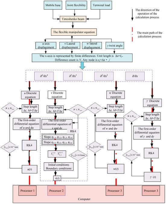
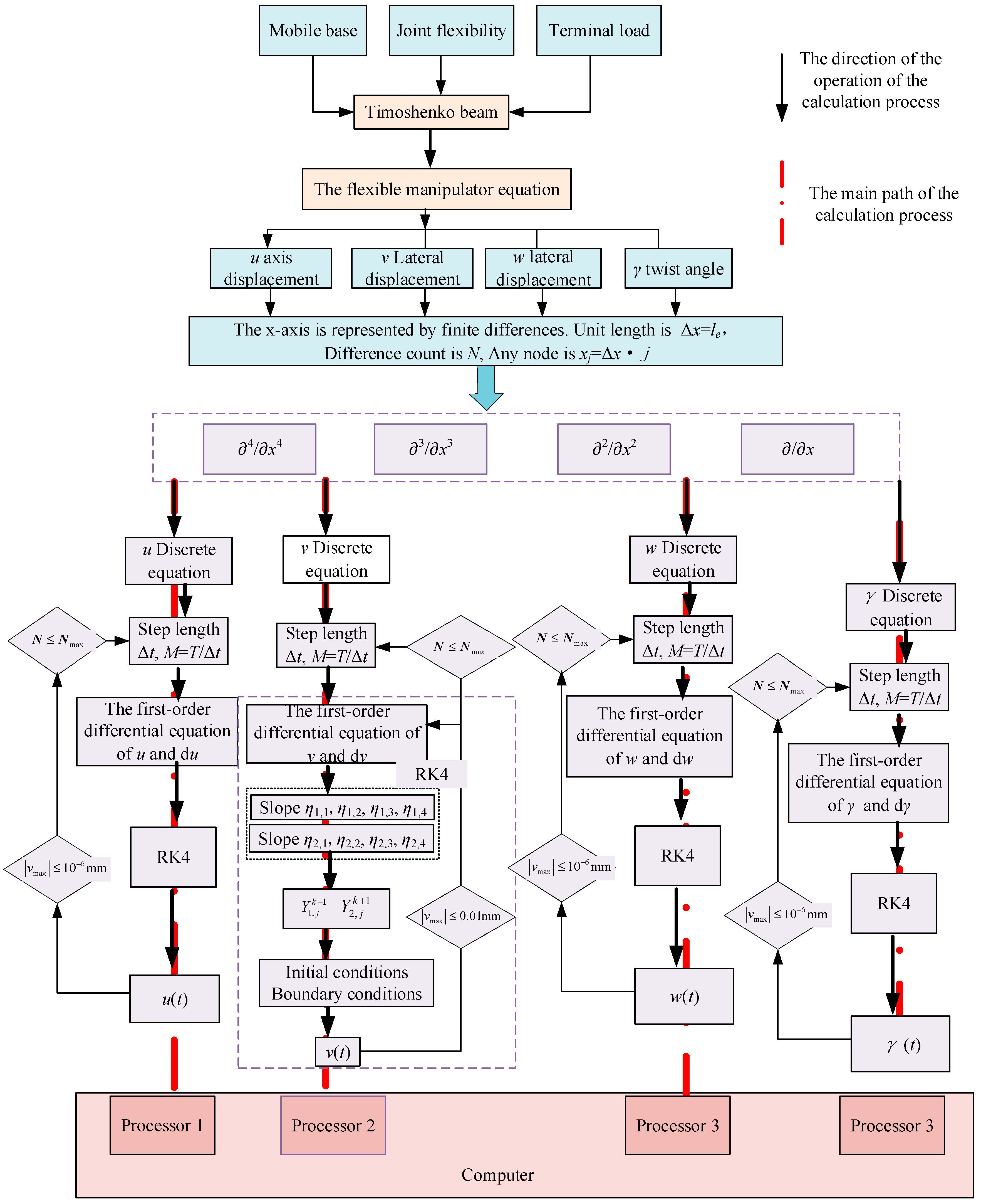
To further accelerate the solution rate, different variables are modularized and a multi-core parallel processing method is adopted to perform solution calculations for each module. The specific process is shown in Figure 3.
Figure 3.
Parallel computing process with double difference and limited resources.
In Figure 3, the terminal load is the target load that the claw at the end of the entire manipulator’s link lN is capable of grasping. By using the method of centralized equivalence, the end load is equivalent to a small ball with a centralized mass of mTip. When the robotic arm grasps the target object and takes on the load, the terminal load is rigidly connected to the final link, and thus they are regarded as a single entity. The terminal load mass is included in the end mass of the final link lN boundary. As shown in Equation (19), mL includes the terminal load mTip, which will affect the force R and torque M in the final link boundary. According to the above calculation process, the time-domain solution of the flexible deformation in this paper can be quickly calculated.
3.4. Link Deformation Modeling Based on Control Characteristics
While Section 3.1 analyzes the deformation of link coupling during space robot motion, the majority of these research works rely on open-loop motion control. They are unable to properly utilize the driving torque to modify the manipulator to meet its real motion and thus cannot effectively suppress manipulator link deformation [27]. In actual motion control, closed-loop control is usually utilized to adjust the motor output torque in real time to meet the needs of the link drive. The feedback control parameters will inevitably affect the link deformation. Therefore, when examining the study of robot link deformation in real-world motion control, its control features must be taken into account. By using the dynamic coupling analysis of manipulator link deformation, it is discovered that the robotic composite motion will significantly impact the deformation to the flexible manipulator under different constraint boundary conditions. To give a theoretical foundation for the subsequent stage of flexible robot dynamics modeling and controller design, this part concentrates on the manipulator link deformation based on dynamic constraint control.
The flexible robot link is a cantilever beam in inertial frame. The expected angle at the simply supported end xi = 0 is θd, the actual angle of the link is θJ, the rotation angle caused by the joint flexible structure is δ, the bending angle caused by the link deformation is w and the torsion angle is γj(j = x, y, z). Therefore, the system error vector is e = [ex, ey, ez]T, where ez is calculated using Equation (36):
In order for the robot to trace the desired trajectory accurately, it must be ensured that the links spin at angles θx→0 and θy→0 in the x and y axes, in addition to the robot joints’ ability to reciprocate at the desired trajectory’s equilibrium position, θd = θJ.
That is, under the control constraint, the manipulator makes ex and ey approach a minimal deviation value, even 0; ez can be expressed as follows:
Based on the principle of moment balance, Equation (38) can be obtained.
where θri is the motor angle of the i-th joint, Nri is the reduction ratio of the i-th joint, θLi is the actual angle of rotation of the fixed end of the i-th link, and Jri is the rotational inertia of the motor.
To meet the demand of the robot control torque, according to the system tracking error and the change rate, the system feedback coefficients Kp and Kd are adjusted to ensure that θJ→θd. However, it is necessary to take into account both the deformation of the link and the control parameters, and to adjust the driving torque in order to seek to satisfy its minimum tracking error. The control driving torque is Equation (39):
In the transient case, by the moment equilibrium principle, both the forces and moments are conserved. Combining the control moments and correcting the link boundaries, the displacement and bending moment at the fixed end of the link xi = 0 are as follows:
where JLi is the moment of inertia of the wheel hub.
The bending moment and the shear at the link end xi = li are obtained.
where is the equivalent rotational moment of inertia of the i+1-st joint acting inversely on the end of the i-th link, and is the equivalent concentrated mass at the end of the i-th link.
Substituting Equations (37)–(39) into Equation (40), the force balance equation is expressed as Equation (42) in the error space:
In the actual motion control of the robot, when compared with the rotational inertia of the manipulator link, the rotational inertia of the motor rotor and the hub (Jr and JL) are small and can be neglected. From the perspective of parameter magnitude comparison, the bending and torsion inertia of the carbon fiber long link is 2 to 3 orders of magnitude higher than that of the motor and hub. The additional torque generated by the inertia of the motor and hub is relatively small compared to the total joint torque. The simulation conditions of this article are as follows: the link length is 1.5 m, the end load is greater than 10 k, and the working frequency is 20 Hz. Under these working conditions, the additional torque generated by the inertia of the motor and the hub will not have a significant impact on the total joint torque. Therefore, it is fully applicable to the model in this article. Therefore, by combining the vertical (38) and (41), the complex constraint boundary of the manipulator under the control law is Equation (43):
where , .
Based on the above analysis, Equations (39)–(43) are the complex constraints of the flexible manipulator joints under the closed-loop control law. The boundary condition (40) is the same as the third term in the second equation of the displacement boundary condition (8) in Section 3.2. The bending moment condition is the same as Qz,i in Equation (15). The initial end boundary conditions of the manipulator are the same as those for xi = 0. The bending moment (41) at the manipulator end is included in Equation (17), and the boundary condition xi = li at the manipulator end is included in the dynamic complex condition. Combining the initial and the end boundary, the boundary conditions of the adjacent links in the spatial manipulator multi-link are corrected, and the specific correction equation is Equation (44):
Substituting Equation (44) into the system Equation (29), using the solution method in Section 3.3, the deformation design parameters of the flexible manipulator under the closed-loop control law are obtained.
4. Modal Identification of Link by Dynamic Time-Domain Response
According to the link deformation analysis in the above Section 3.1 and Section 3.2, the dynamic response of the flexible manipulator based on energy conservation, complex constraint boundaries, and control constraints is more in line with the real working conditions than the ideal cantilever beam vibration response. However, this method is not conducive to modeling the dynamics of flexible manipulators, which still need to be analytically simplified before modeling. Therefore, based on the dynamic coupling response of link deformation, the vibration frequency and mode of link under AMM are identified and modified to obtain a more accurate description model with fewer generalized variables. This is of practical significance to the modeling of flexible space robots.
The research purpose of modal analysis is to obtain modal parameters such as vibration frequency, mode shape and damping ratio of the flexible manipulator [16]. Based on the research of these parameters, the dynamic behavior of flexible robots can be further analyzed and studied. However, due to the complexity of the environment and the limitations of the existing testing technology, the current experimental testing methods can only obtain the deformation and vibration response of the mechanical components of the system under certain working conditions. It cannot solve the modal parameters of the system through artificial excitation and experimental modal analysis. In particular, it is difficult to obtain modal parameters of complex system structures or large-size structures. Therefore, mode recognition based on time-domain response signals is very meaningful.
To solve the problem of link deformation mode identification in large size and complex structure body, many scholars have proposed the learning method based on flow shape for identification. Using the system time-domain response as a dataset, this method extracts the modal information of the link deformation in a nonlinear way, such as Local Linear Embedding Algorithm (LLEA), Laplace Algorithm (LA), and Isometric Mapping Algorithm (ISA) [6]. When the modal parameters of large-size structures are proposed using the LLAE method, their time-domain response data are regarded as a high-dimensional dataset. The system modal parameters are intrinsic properties (dimension, sparsity, resolution) of this dataset [6]. In this subsection, the link deformation time-domain response data in Section 3.1 is used as a dataset to extract the intrinsic frequency and vibration mode by LLAE.
According to the link coupling deformation analysis in Section 3.1, the link deformation in different directions can be extracted as the output response. The link deformation response at time t and position x in each direction of the manipulator is selected as the dataset. They can be written as Dmn= [d1, d2,…,dn]∈ℜm×n. Based on dataset Dmn, the modal information of link deformation is extracted by the LLAE method. The specific steps are as follows [6].
First, the number of neighborhood points dk is determined. Using Equation (45), the Euclidean distance between data point di and other data points dj is computed and the i closest adjacent point to dk is obtained.
The least squares method can be used to solve the minimum cost function, and the weight under the neighborhood point dk is wij. If di is not a neighborhood point of dk, then wij = 0.
To reduce the data dimensionality, the low-dimensional matrix M = (I−W)T(I−W) is embedded in the dataset, which is composed of the 2-nd to the i1-1st smallest eigenvectors, and i1 is the reduced dimension. The low-dimensional embedding vector di can be calculated by using the minimizing embedding cost function Equation (47) to minimize the low-dimensional reconstruction error e(D).
where di is a vector satisfying and .
Based on the Rayleigh–Ritz method, the time-domain response of the manipulator can be expressed as a linear combination of modal modes and modal coordinates. In the process of finite element analysis and experimental data acquisition, the system of the manipulator will be discretized into m monitoring points and the time t is discretized into n sampling points, and then the manipulator system response is obtained.
where Nr is the modal truncation number, dmn is the link deformation response, Dmk is the vibration mode vector, and qkn is the main generalized coordinate vector.
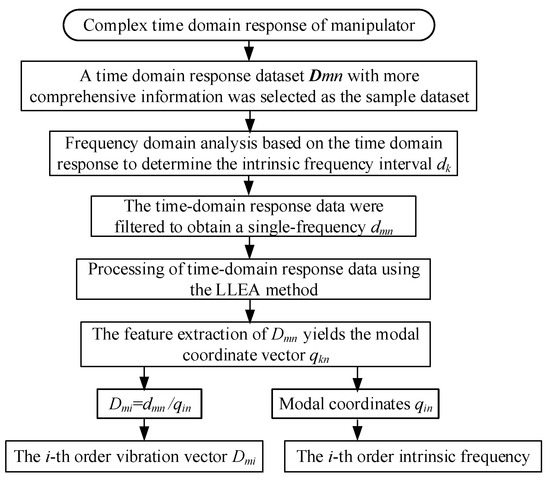
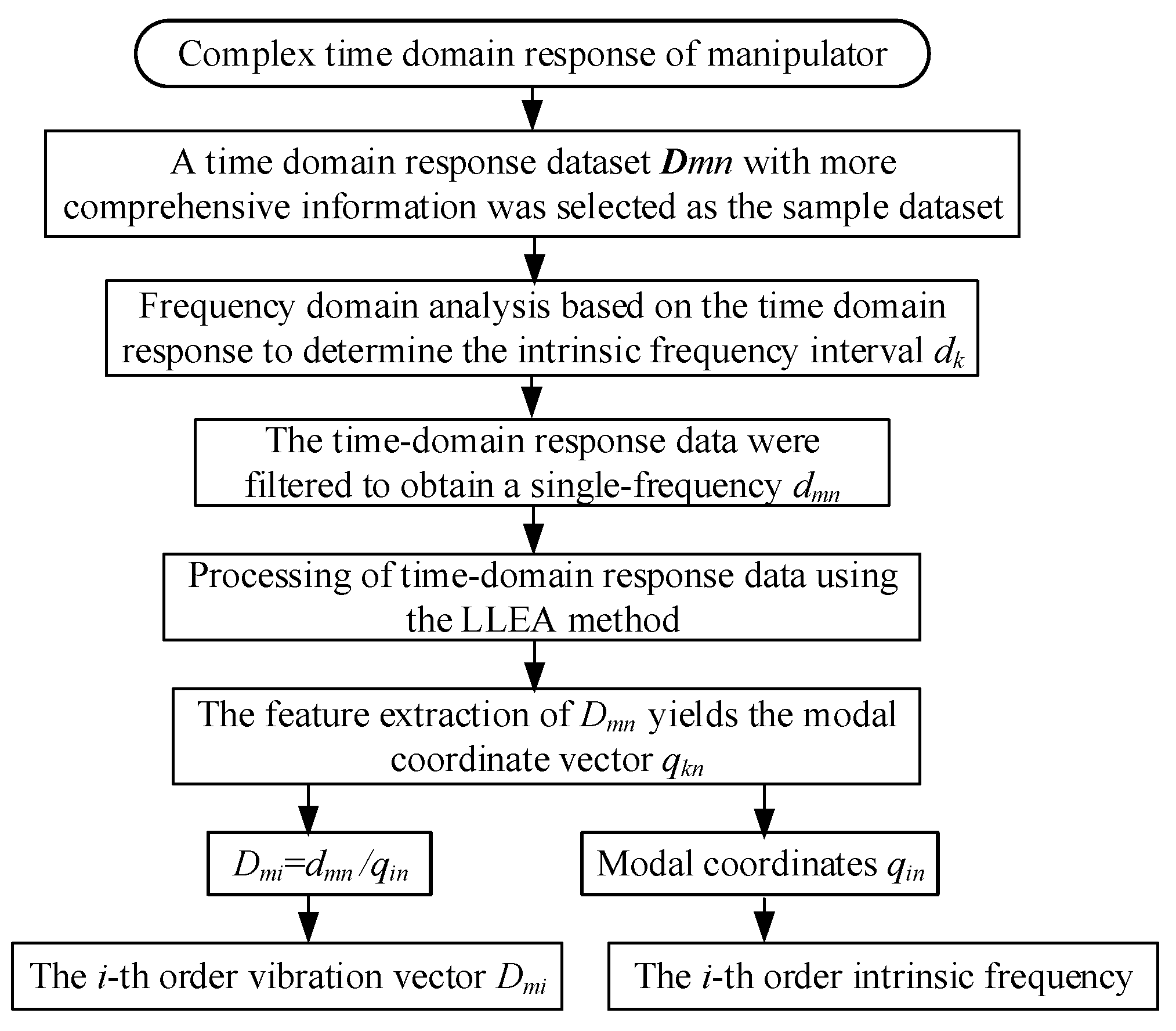
The basic steps of modal recognition based on the LLAE method are shown in Figure 4.
Figure 4.
Modal recognition process by time-domain response of flexible link.
To obtain the approximate actual mode of the dynamics modeling of the multi-degree-of-freedom manipulator, the vibration dynamics system of manipulator is analyzed to obtain its frequency response.
where M, C and K are the matrices of mass, coupling and stiffness, respectively, and f(t) is the external input force.
For a manipulator system with real modes, the output displacement response is . Di is the i-th mode shape and qi is the i-th mode coordinate. Substituting Equation (51) into Equation (50), based on the theory of vibrational orthogonality [7], the motion Equation (49) can be decoupled as follows:
where mi is the modal mass, ξi is the damping ratio, and ωi is the natural frequency of the i-th order.
Equation (50) is solved by considering the application of a pulse load on the k-th degree of freedom. The pulse load is: if i = k, fi(t) = f0δ(t), else if fi(t) = 0, the modal coordinate is used to represent the i-th order acceleration response as:
where ϕki is the k-th element of the i-th mode, φi is the i-th mode phase, and ωi is the i-th vibration frequency
The system impulse acceleration response of the manipulator on k-degree degrees of freedom is as follows:
where is the phase difference between the kth and p-th elements of the i-th-order vibrational vector.
According to the actual mode of the system, the link vibration mode is a real number, and the real-number vibration mode is obtained.
Using the Hilbert transform method, the system modal impulse response of the manipulator is solved, and the instantaneous amplitude and instantaneous phase equations are shown in Equation (54).
By means of the empirical modal method, the time-domain response data are decomposed into a number of intrinsic modes, from which the physically significant intrinsic modes are selected. Then Hilbert transform is used to obtain the amplitude spectrum and phase spectrum of each inherent mode. Using the phase spectrum of Equation (54), the intrinsic frequency and damping ratio of the manipulator are derived.
where is .
In the above-mentioned linkage solution and modal identification process, there are four key parameters: Nl, Δt, εv and dk.
- Link segmentation number Nl: Insufficient segments cause under-sampled elastic deformations and distorted vibration/modal outputs; moderate segmentation fully captures 3D flexural, axial and torsional responses without redundant computation, while excessive discretization merely raises computational overhead without altering core dynamic characteristics. The simulation in the entire text uniformly adopts Nl = 12, which takes into account both the calculation accuracy and the computational efficiency.
- RK4 time step Δt: Overlarge steps filter transient high-frequency coupling vibrations and distort temporal profiles; moderate or small steps fully retain complete vibration signatures, with marginal step adjustments exerting negligible influence on primary dynamic behaviors. This paper adopts a step size of Δt = 2.5 × 10⁻² s. It can fully capture the steady-state periodic vibration and instantaneous sudden deformation, and is stable enough to meet the deflection convergence criterion .
- Convergence threshold εv: Loose thresholds truncate subtle high-frequency micro-vibrations critical for orbital servicing, moderate thresholds balance computational accuracy and efficiency, and stricter criteria only induce redundant iterations with unchanged deformation curves. This paper employs a tight constraint threshold εv = 6.67(10−6), which can accurately analyze the flexible vibration of a 1.5 m boom while avoiding unnecessary iterations.
- LLE neighborhood size dk: Too few neighbors fail to reconstruct manifold features and bias modal extraction; a moderate neighborhood clearly separates physical vibration modes and suppresses noise, whereas an oversized neighborhood only introduces spurious high-order modes without corrupting dominant modal information. This article uniformly selects dk = 10 for modal identification, aiming to balance the integrity of feature extraction and the anti-noise capability.
All parameters are set within a wide and moderate stable working range. Within this range, minor adjustments to the parameters only affect the computational efficiency and do not alter the core deformation and modal results. Severe performance degradation of the output occurs only under extreme parameter values, indicating that the proposed modeling and identification framework has good parameter tolerance and reliable robustness.
5. Simulation and Experiment
5.1. Model Verification and Analysis
To verify the validity of the article mode, a 2DOF flexible space robot in Figure 3 on a mobile platform is taken as the research object [13]; it is a three-dimensional space model. Firstly, o0-x0y0z0 is the inertial coordinate, and oB-xByBzB is the center of the base coordinate. The first joint of the manipulator is installed at the oByB axis of the base and is offset by 0.75 m. The coordinate is oi-xiyizi (i = 1,2), and the joint central axis coincides with oizi. The joint structure is equipped with an elastic damping structure whose equivalent stiffness is ki and the equivalent damping is ci. The manipulator link is fixed on the wheel hub, and the axis oixi coincides with the axis of the link when the link without deformation. An actuator with a two-finger structure at the end of the manipulator arm has a concentrated mass of 10 kg. The gravity coefficient in this paper is 9.8 × 10⁻⁴ N/kg. The overall structure of the space robot is shown in Figure 5, and the specific parameters are shown in Table 1.
Figure 5.
The overall structure of 2DOF flexible space robot.
Table 1.
Physical parameters of flexible space robot.
In Table 1, the mechanical arms B1 and B2 are aerospace-grade carbon fiber material. The shear modulus within the core plane of this material is typically 3.8–5.6 GPa. In this article the shear modulus is 7.5 GPa [28].
In MATAB R2023b, the joint initial values are θ1 = θ2 = 0. The initial deformation value of the link is ui = vi = wi = γji = 0, (j = x, y, z). The torque is r N·m and N·m, respectively. By the actual convergence results of the simulation, the simulation step size is adjusted, and it is Δt = 2.5 × 10⁻² s. The simulation process is calculated by odel5s, and the simulation time is 10 s.
To verify the effectiveness of the link deformation analysis method, the dynamic Coupled Analysis Model (DCAM), the flexible joint–flexible link analysis model under ideal hypothesis mode (FJ-FL-AMM) [29] and the analysis model of flexible joint–rigid manipulator (FJ-RM) are simulated and compared [30]. The correctness and calculation accuracy of the classical modeling method (FJ-RM) are verified, and can be used as a reference model for the verification of the modeling method in this paper. Firstly, in the FJ-FL-AMM system, the link deformation is described by AMM [31]. The link boundary condition at one end is fixed and the other end is free, while the initial conditions are 0. Then, the characteristics of the flexible joint are described by the lumped parameters. The dynamics model of the 2DOF flexible space robot is constructed based on the Lagrange method. Secondly, in the FJ-RM system, the manipulator link is regarded as a rigid link, and the dynamics model of the flexible joint–rigid link robot is established by using the Newton–Euler method. Finally, three system models are simulated by MATAB R2023b.
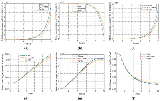
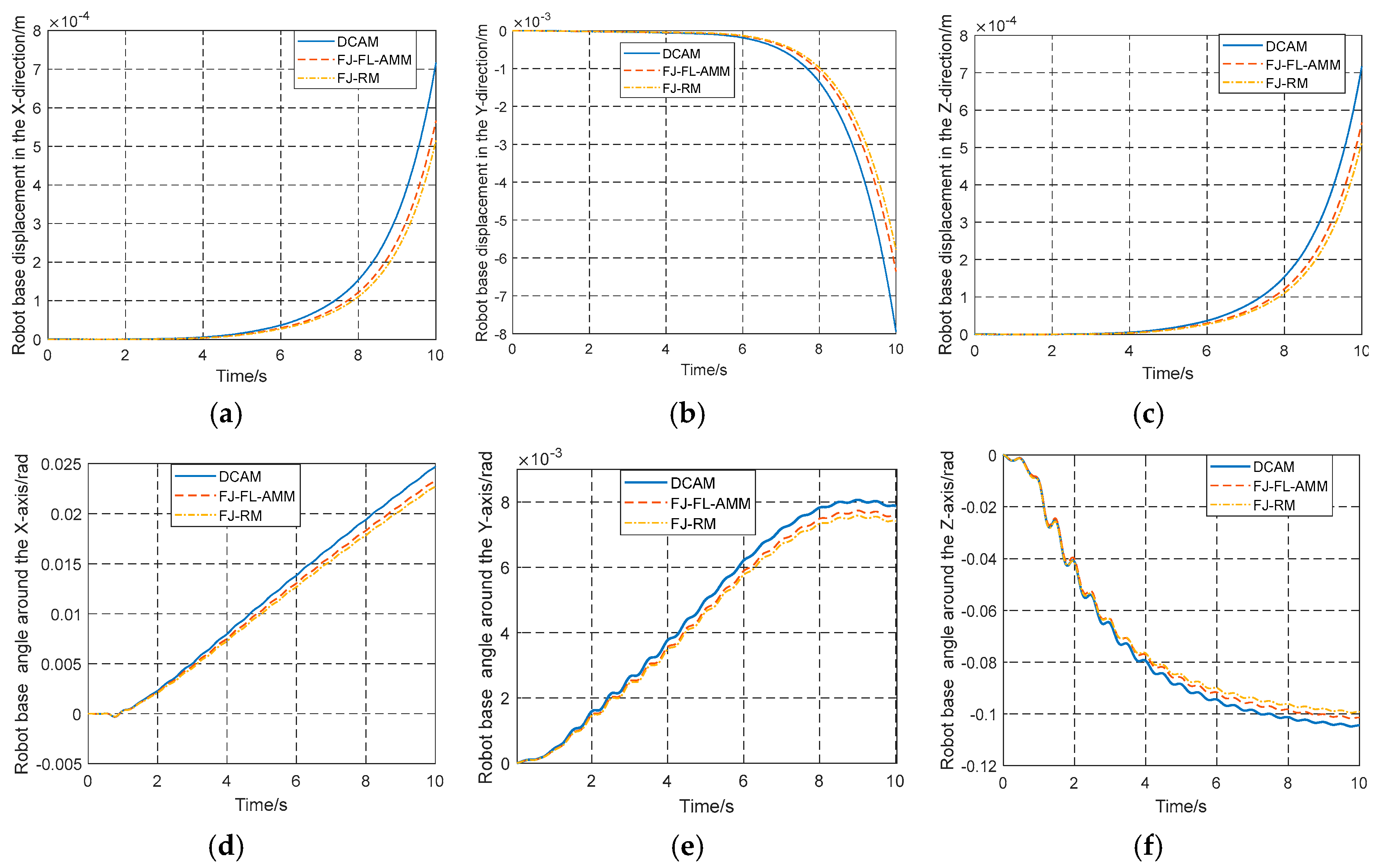
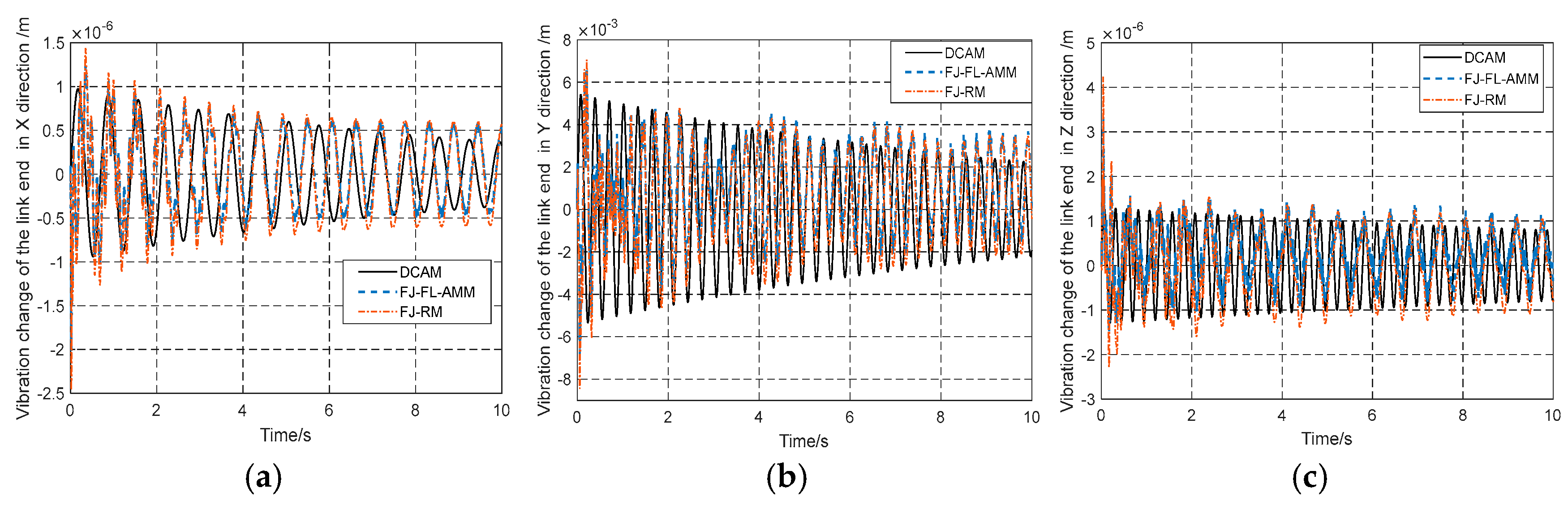
By the curve changes in Figure 6, there is no significant change in the posture of the pedestal calculated by the three models within 0 ≤ t ≤ 3 s. After 3 s, compared with the FJ-RM modeling method, the posture of the robot base in DCAM changes greatly. The maximum relative error is 8.55%. The error is lower than the 10% allowable threshold commonly used in the aerospace field [12]. But their general trends are basically the same. This verifies the correctness of the model presented in this paper. Meanwhile, compared with the FJ-FL-AM, the pose of the base in DCAM changes greatly, which proves that the flexible joint also has a certain influence on the base’s stable operation. Especially after 5 s, the curve deviation under the two models gradually becomes larger, which proves that there is an interaction between the base movement and the flexible manipulator, which is also consistent with the previous research conclusions [29] (coupling analysis of the flexible base and the manipulator). This further proves the correctness of DCAM.
Figure 6.
Pose changes of space robot base under different analysis models: Position: (a) X-direction, (b) Y-direction, (c) Z-direction; attitude: (d) X-axis, (e) Y-axis, (f) Z-axis.
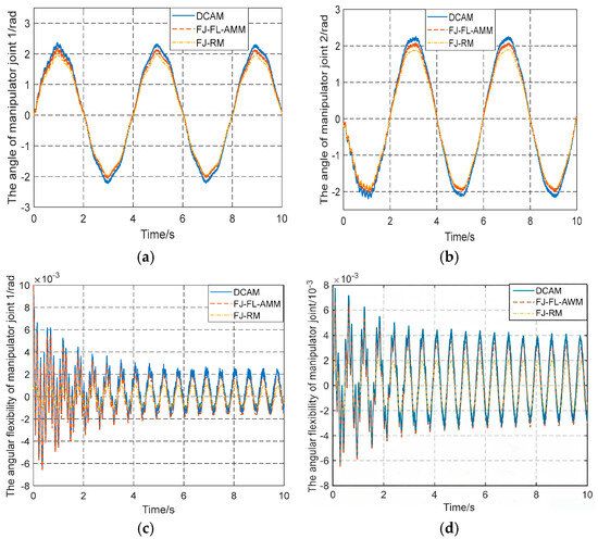
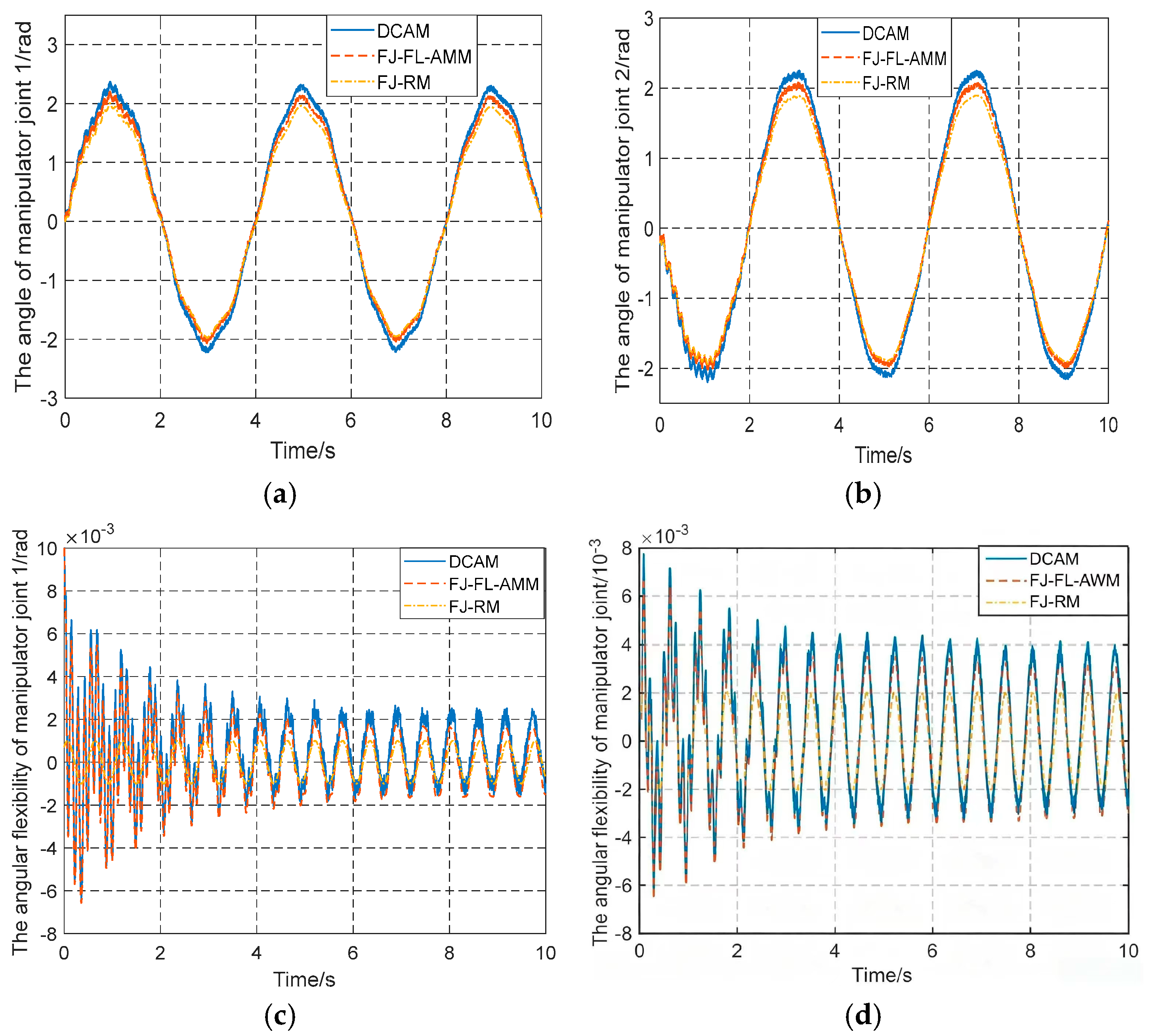
By the analysis of the manipulator joints in Figure 7, the angle change trend of the manipulator joint under the three different analysis models is consistent. Under the action of sinusoidal driving torque, the link deformation counteracts the manipulator operation, which makes the peak value of the joint angle fluctuate. Compared with the joint response of FJ-FL-AMM, the joint response in DCAM is more obvious. The curve changes in Figure 6 show the changes in robot joint flexibility under different FJ-FL coupling structures. When the FJ-RM model comprehensively considers joint flexibility and damping, and the ratio between equivalent stiffness and equivalent damping is constant, the joint flexibility changes periodically. When the deformable elastic force of the link reacts on the joint structure, the joint flexibility changes will be intensified, especially under DCAM. Theoretically, the link deformation in DCAM will increase the joint angle change, which conforms to its energy conservation law. And it will also act on the flexible joint change, which also conforms to its energy conservation.
Figure 7.
Joint change for space robots under different analysis models: (a) joint angle 1, (b) joint angle 2, (c) joint flexibility 1, (d) joint flexibility 2.
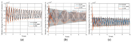
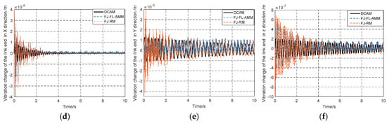
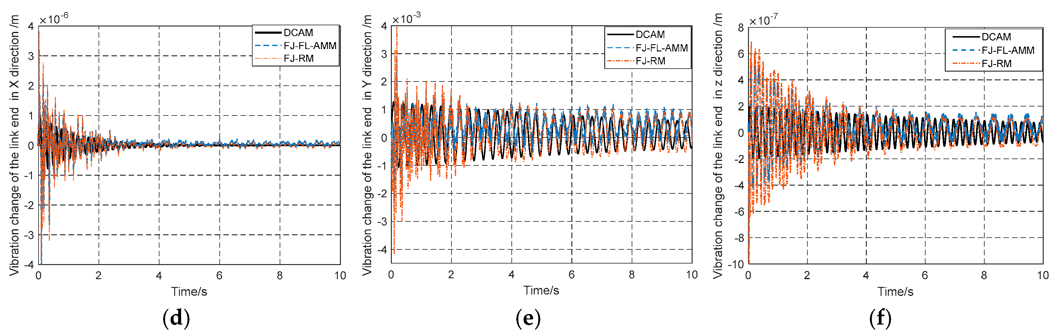
By the flexible variation curves of link 1 and link 2 in Figure 8, it can be seen that the study analyzed the manipulator link deformation from a three-dimensional perspective. By the setting of the floating coordinate and the joint coordinate, compared with the axial tensile deformation in the X-direction in Figure 8a,d and the shear deformation in the Z-direction in Figure 8c,f, the transverse bending deformation in the Y-direction in Figure 8b,e is larger, with an order-of-magnitude difference of 103, which is in accordance with the bending deformation of links with Euler–Bernoulli beams as the standard beams. The above analysis proves the correctness of the dynamic coupling analysis model of link deformation for flexible space robots established in this paper.
Figure 8.
Flexible vibration of space robot link under different analysis models: Link 1: (a) X direction, (b) Y direction, (c) Z direction; Link 2: (d) X direction, (e) Y direction, (f) Z direction.
During the operation of the actual space robot, the coupling link deformation is larger when considering the robot base motion, joint flexibility, damping and other factors, which is consistent with the principle of the system energy conservation. Although the system control input and the system action are relatively smooth, with the change in time t, the coupling link bending deformation will appear suddenly (3.5 s, 5.5 s and 7.5 s in Figure 8b,e). This is due to the rapid change in the coupling link mass geometry leading to the system’s instability. As the changes in the quadratic terms of the joints trajectories for the robot system are large, they can obtain large accelerations (2 s, 4 s, 6 s, and 8 s in Figure 6a,b). And as the curvature of the robot base trajectories changes drastically (6 s and 8 s in Figure 4), the link deformations of the flexible space robots produce large changes. This further proves the necessity of the dynamic coupling analysis of link deformation, and indirectly proves the correctness of its analytical model.
This study is not only applicable to the flexible deformation analysis of large components such as space robots and solar sail panels, but also to the flexible deformation analysis of operators on mobile platforms such as interplanetary exploration vehicles, large boom cranes and large marine manipulators. It integrates the non-fixed carrier base motion, complex joint structure and large-size body deformation for analysis and research, and is significantly superior to the single body deformation analysis.
5.2. Numerical Simulation and Characteristic Analysis
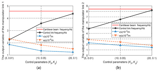
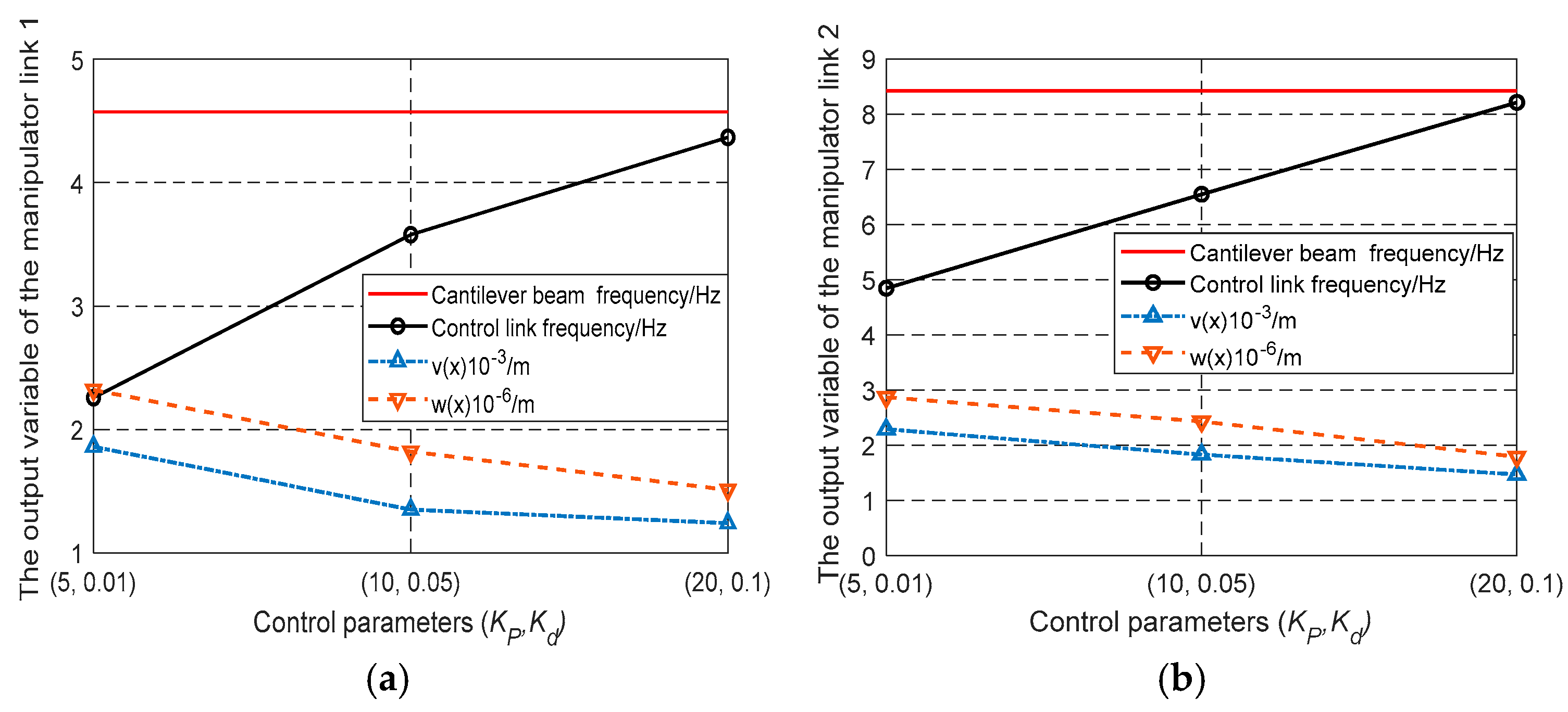
To analyze the link deformation characteristics of flexible manipulator under the control law, this section takes the robot shown in Figure 3 as the object for calculation and analysis. The joint’s starting value is θ1 = θ2 = 0. The initial value of the link deformation is , (j = x, y, z). The displacement and torsion angle of the robot link deformation can be obtained either directly or indirectly during the robot’s actual operation. The feedback control algorithm is used to control the stable operation of the robot base, and the control parameters are kept unchanged in the subsequent simulation. Finally, different control parameters are set by Equation (42). Using the solution method in Section 3.3, the link deformation is compared. The pose control parameters of the base are KBP= diag([KBp,KBv]), KBp= diag([25,25,25]) and KBv= diag([2,2,2]). When the link deformation of the manipulator is not suppressed, three different combination parameters are used to design the joint control parameters in Table 2. To further analyze the change law of the influence of control parameters on the link deformation, the control parameter pair is taken as the horizontal coordinate variable, while the system frequency and deformation response under the control law are taken as the longitudinal variable, and their values are further simulated, as shown in Figure 9.
Table 2.
Changes in link deformation in frequency domain and time domain under different control parameters.
Figure 9.
The output variables of the mechanical system under different control parameters: (a) Link 1, (b) Link 2.
When determining the tip load mass of the link, the data in column 3 is the base frequency of the cantilever beam under fixed-end load boundary conditions. Based on this, the vibration frequency of the first link and the second link in column 3 can be quantified. And the vibration foundation frequency of the link decreases with the increase in the link tip mass. As the tip mass of the link is 4 times higher in two different cases, its base frequency is reduced by 50%. This is consistent with the research results in the literature [27] (the study gives the research values and results of the flexible robot arm at 0 kg and 3 kg), and the results of the above research are consistent with the classical vibration theory. The data in column 5 are the vibration frequencies of the EBTT coupled system under the elastic damped end-load boundary. This system increases with the increase in joint stiffness, but its end transverse bending v(li) decreases [32]. The joint damping of the robot is 0.05, and the joint stiffness is the value in column 4 in Table 2. Based on the above analysis, compared with the research results in reference [33] (which provides stiffness parameter design and robust adjustment parameters of flexible manipulator), the research and analysis results in this paper are more comprehensive and specific.
Combining the constrained boundary conditions and joint stiffness coefficients in Equation (43), the vibration frequency and the link tip bending displacement in the control system can be calculated by using the solution methods in Section 3.3 and Section 3. The calculated results are the values in columns 8 to 10 in Table 2, and are compared and analyzed with the values of the cantilever beam and coupling system in Table 2. When the system control parameters (Kp and Kd) are small, the link vibration frequency in the control system is smaller compared to the link vibration frequency in the cantilever beam or coupled system. And link vibration frequency is reduced by about 40%. According to the analysis of the curve change trend in Figure 8, the flexible link deformation decreases with the increase in the control parameters. And the link vibration frequency will gradually approach the foundation frequency of the cantilever beam in the control system. This is because within the range of allowable control parameters, KP increase accelerates the instantaneous response speed of the system, and Kd decrease reduces the overshoot parameters, and this overcomes the system oscillation of the manipulator. By the above analysis, the link vibration frequency in the control system is lower than that of the cantilever beam and the coupling system, although the joint structure has a damping constraint effect with the increase in control parameters. The manipulator link vibration tends to be similar to that of the cantilever beam with lower frequency because the control parameters cannot be increased infinitely, thus improving the stability of the whole robot system.
5.3. Numerical Simulation and Modal Analysis
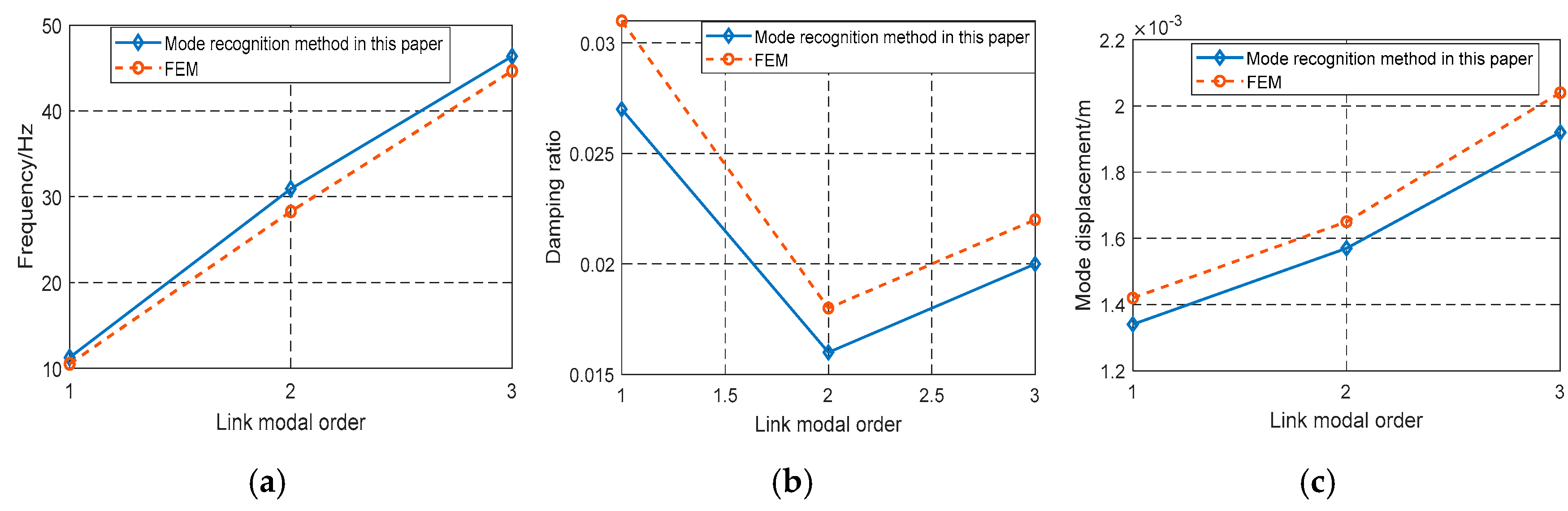
To verify the validity of the modal identification model, the second link of the manipulator in Figure 3 is used as the object. And the time-domain response of the manipulator link deformation is calculated by using the solution method in Section 2. Twelve test points are selected in the axial direction of the link, and the deformation response acceleration of each monitoring point is obtained. Then, under the pulse excitation signal with a sampling frequency of 100 Hz and sampling time of 10 s, the numerical simulation is carried out on the selected monitoring points. The natural frequency, modal shape and damping ratio of the flexible link are calculated by using the time-domain response mode identification method in Section 4. Meanwhile, ANSYS Workbench 2024 R2 is used to simulate the modal analysis of the link deformation. Firstly, the three-dimensional model of the space robot is constructed by Solidworks and it is imported into Ansys. In the modal analysis module, different boundary conditions are set at the two ends of the robot link. The boundary condition at one end is a rotatable spring damping structure, and the other end boundary condition is a concentrated mass load. Secondly, in the axial direction of the manipulator, the deformation and displacement of the manipulator at 12 monitoring points are selected for monitoring. The response data of the link deformation can be obtained by the monitoring data. On this basis, the modal analysis module can be used to extract the vibration frequency, modal damping ratio and modal mode of the link deformation. Finally, the modal identification results of finite element analysis are compared with those of this paper, and the specific results are shown in Table 3. Modal parameters under different recognition methods are compared in Figure 10. On this basis, using the modal confidence function method in Ref [6], the correlation of the modal information identified by the above two methods is analyzed. The validity of the modal information identified in this paper is evaluated.
Table 3.
Comparison of modal parameters based on different methods.
Figure 10.
Modal parameters of link deformation under different identification methods: (a) Frequency, (b) Damping ratio, (c) Mode displacement.
Comparative analysis of the frequencies under this paper’s modal identification method and the finite element method through Table 3 and Figure 10a reveals that the maximum relative error between the two is not more than 8.55%, which verifies that the modal identification of the frequencies in this paper is feasible. By comparing the damping ratios of the two recognition methods in Figure 10b, it can be seen that the maximum relative difference of the damping ratios of the two modes is 4%, which verifies the correctness of the damping ratios of the mode recognition. Figure 10c is used to compare the modal displacement of the flexible manipulator end with the two identification methods, and it is found that the maximum displacement difference between the two methods is 5%, which further verifies the correctness of the mode identification method proposed in this paper. Based on the confidence criterion of modal recognition, it can be seen that the correlation confidence between the modal recognition method in this paper and the finite element method exceeds 0.93 and approaches 1. Therefore, we can consider that the modal frequencies and modal modes obtained by the two methods are basically the same, which proves the validity of the modal information recognition method in this paper. Based on the modal information recognition method presented in this paper, the modal parameters of the link deformation response for flexible space robots in complex systems can be identified. By using the identified modal information, the link deformation of flexible space robots is described, which is very beneficial to accurate robot dynamics modeling.
Based on the above Section 5.1, Section 5.2 and Section 5.3, the advantages of the model established in this paper are further clarified.
Compared with the traditional FJ-FL-AMM and FJ-RM modeling methods, the proposed DCAM rigid–flexible coupling analysis method has multiple verified advantages reflected by all groups of simulation curves and tabular data: as shown in Figure 6 base pose curves, this method revises link boundary conditions to fully incorporate floating base inertia, joint stiffness and damping, accurately capturing the mutual rigid–flexible excitation between the spacecraft platform and manipulator that traditional ideal cantilever-based models fail to reproduce.
Figure 8 link vibration results prove it adopts complete 3D Timoshenko beam theory and double finite difference parallel solving to comprehensively calculate axial stretch, bidirectional bending and torsional deformation of links, overcoming the 2D deformation limitation of the Assumed Modes Method; Table 2 and Figure 9 control parameter simulations reveal it innovatively embeds PD closed-loop feedback torque into dynamic constraint equations, enabling quantitative analysis of how proportional and differential gains affect system natural frequency and terminal vibration amplitude, a capability absent from open-loop traditional models.
Figure 7 joint flexibility curves show it can fully reflect the coupling amplification effect of link elastic counter-torque on joint torsional oscillation in line with energy conservation rules, unlike rigid-link FJ-RM which ignores all arm vibration; Table 3 modal comparison data verifies its LLE time-domain modal identification algorithm generates frequency, damping and mode shape results with a maximum relative error of only 8.55% against high-precision Ansys FEM and MAC coefficients above 0.93, delivering more real structural modal information than artificially preset ideal modes; meanwhile, the multi-core parallel double finite difference calculation flow in Figure 3 balances computational accuracy and efficiency better than fine-mesh finite element methods, so overall this method realizes more authentic physical characterization, higher modal identification precision and quantifiable multi-factor coupling analysis unavailable to traditional simplified models, perfectly matching the actual on-orbit operating conditions of space robots.
6. Conclusions
In this paper, the deformation description of a space flexible manipulator under dynamic coupling is studied.
Firstly, the flexible space robot is equivalent to a flexible manipulator model of a movable platform. On this basis, joint flexibility, damping and load effects are introduced into the boundary conditions of the link, and the complex boundary conditions are modified. Based on the principle of energy conservation and moment balance, a dynamic coupling analysis model of the link deformation for space robot with coupling structure FJ-FL is proposed. By the double finite difference method, the solution flow of the link deformation is given and the time-domain response is calculated. Secondly, in the complex boundary conditions of link deformation, the closed-loop control parameters are introduced, and the dynamic constraint equation of link deformation is established and solved. Then, the time-domain response of link deformation is used as a dataset, and the modal recognition method of LLAE is used to identify the modal information of link deformation of a space manipulator. Finally, numerical simulation is used to verify the correctness of the analytical model. Compared with the classical link analysis models FJ-FL-AMM and FJ-RM, the dynamic coupling analysis model proposed in this chapter comprehensively considers the influences of robot base, joint flexibility, joint damping and other factors on link deformation, so as to obtain a response closer to the actual working condition. With an increase in control parameters, the flexible deformation of the link decreases. In the control system, the vibration frequency of the link will gradually approach the base frequency of the cantilever beam. Based on the confidence criterion of modal recognition, it can be seen that the correlation confidence between the modal recognition method in this paper and the finite element method exceeds 0.93 and approaches 1. On this basis, the modal information recognition method based on time-domain response in this paper has a strong practical significance for establishing the dynamic model of flexible space robots. And this lays a theoretical foundation for the accurate dynamic modeling of subsequent space robots.
Author Contributions
F.Z.: Conceptualization, Supervision, Data curation, Investigation, Formal analysis, Writing—original draft, Funding acquisition, Resources. N.L.: Writing—review and editing. All authors have read and agreed to the published version of the manuscript.
Funding
Shaanxi University of Technology talent launched a special project (Funder: Shaanxi University of Technology; Funding Number: SLGRC202417), Project of the University Engineering Research Center of the Shaanxi Provincial Department of Education (Funder: Shaanxi Provincial Department of Education; Funding Number: 24JR044), Key Laboratory Project of Advanced Manufacturing and Health Management for Aviation Components in Shaanxi Province (Funder: Advanced Manufacturing and Health Management Laboratory for Aviation Components in Shaanxi Province; Funding Number: SLGKFKT03).
Data Availability Statement
All data generated or analyzed during this study are included in this published article and they can be both public and effective.
Conflicts of Interest
The authors declare that they have no known competing financial interests or personal relationships that could have appeared to influence the work reported in this paper.
References
- Xi, H.; Chen, B.; Tian, J. Dual-observer-based composite robust vibration control for a rigid-flexible hybrid space robot-target combination. Nonlinear Dyn. 2025, 113, 16545–16569. [Google Scholar] [CrossRef] [Scilit]
- Dong, Z.; Wang, L.; Zhu, Y. Motion planning of free-flying space robots for tracking relative motion tumbling targets by sequential optimization via reinforcement learning. Acta Astronaut. 2025, 235, 463–474. [Google Scholar] [CrossRef] [Scilit]
- Yang, Y.; Su, Q.; Hui, W. Adaptive model-free finite-time tracking control for flexible-link manipulator with parametric and non-parametric uncertainties. Nonlinear Dyn. 2025, 113, 13339–13355. [Google Scholar] [CrossRef] [Scilit]
- Yang, Y.; Zhang, Z.X.; Liu, M.; Han, H.H.; Wei, J.; Cao, D.Q. Dynamic modeling and analysis for a large flexible spacecraft with antenna trusses and solar wings. Appl. Math. Model. 2026, 150, 116405. [Google Scholar] [CrossRef] [Scilit]
- Shang, D.; Fan, X.; Yin, M. Dynamic modeling and speed control for flexible manipulator with elastic joint based on fractional-order disturbance observer. J. Braz. Soc. Mech. Sci. Eng. 2025, 47, 513. [Google Scholar] [CrossRef] [Scilit]
- Ji, N.; Huang, Z.Y.; Liu, J.K. Bilateral consistency and vibration control for nonlinear flexible Timoshenko robotic arms in signed directed communication graph with quantized control inputs. Commun. Nonlinear Sci. Numer. Simul. 2026, 152, 109334. [Google Scholar] [CrossRef] [Scilit]
- Yu, J.W.; Wu, M.Y.; Ji, J.C.; Yang, W.H. Neural Network-Based Region Tracking Control for a Flexible-Joint Robot Manipulator. J. Comput. Nonlinear Dyn. 2024, 19, 021003. [Google Scholar]
- Zhang, Y.; He, L.; Chen, J. Neural Network Adaptive Hierarchical Sliding Mode Control for the Trajectory Tracking of a Tendon-Driven Manipulator. Chin. J. Mech. Eng. 2025, 38, 18. [Google Scholar] [CrossRef] [Scilit]
- Gupta, N.; Pratiher, B. Hydrodynamic modeling with cascade PID control and experimental realization of a two-link flexible underwater robotic manipulator. Ocean Eng. 2025, 335, 121545. [Google Scholar] [CrossRef] [Scilit]
- Yan, X.; Shi, L.; Shan, M. Vibration-suppressed trajectory planning for flexible space manipulators during on-orbit operations. Nonlinear Dyn. 2025, 113, 20977–21000. [Google Scholar] [CrossRef] [Scilit]
- Hao, C.F.; Dong, L.L.; Yan, J. Modal recognition method combining LLE and HHT based on test response. Proc. Chin. Mech. Soc. 2017, 12, 12–36. [Google Scholar]
- Zhou, Y.P.; Lou, J.Q.; Chen, T.H. Identification and experiment of coupling dynamics model of flexible arm system driven by servo joint. J. Vib. Shock. 2019, 38, 278–284. [Google Scholar]
- Pravesh, K.; Barun, P. Modal characterization with nonlinear behaviors of a two-link flexible manipulator. Arch. App. Mech. 2019, 89, 1201–1220. [Google Scholar] [CrossRef] [Scilit]
- Do, T.T.; Vu, V.H. Linearization of dynamic equations for vibration and modal analysis of flexible joint manipulators. Mech. Mach. Theory 2022, 167, 104516. [Google Scholar] [CrossRef] [Scilit]
- Li, C.Y.; Wang, X.; Cheng, Y.; O’Regan, D. Boundary stabilization for a nonlinear flexible beam under an adaptive fractional-order proportional-integral control. Commun. Nonlinear Sci. Numer. Simul. 2026, 152, 109352. [Google Scholar] [CrossRef] [Scilit]
- Kraïem, S.; Rognant, M.; Waitman, S.; Chelikh, I.; Biannic, J.M. Dynamics and robust control of a space manipulator system servicing a satellite with flexible appendages. IFAC J. Syst. Control 2025, 33, 100328. [Google Scholar] [CrossRef] [Scilit]
- Masoumi, M.; Kohansal, N.; Eftekhari, M. Nonlinear vibration of flexible two links manipulator with variable cross sections. Commun. Nonlinear Sci. Numer. Simul. 2026, 152, 109250. [Google Scholar] [CrossRef] [Scilit]
- Shang, D.Y.; Liu, J.Q.; Yin, M.; Li, X.P. Speed fluctuation suppression strategy for flexible joint-flexible link robotic manipulators via servo motor measurement feedback signal. Measurement 2026, 257, 118871. [Google Scholar] [CrossRef] [Scilit]
- Ouyang, Q.H.; Chen, B.; Xia, H.Y.; Liu, H.X.; Tian, J.; Zhang, Y.Z. Optimal trajectory planning for coupled vibration suppression of a flexible base and space flexible manipulator. Aerosp. Sci. Technol. 2025, 165, 110511. [Google Scholar] [CrossRef] [Scilit]
- Liu, Y.; Yao, X.Q.; Zhao, W. Distributed neural-based fault-tolerant control of multiple flexible manipulators with input saturations. Automatica 2023, 156, 111202. [Google Scholar] [CrossRef] [Scilit]
- Su, J.; Liu, L.X. Simulation research on active control of low frequency modal vibration of double-joint flexible manipulator. Int. J. Ind. Syst. Eng. 2021, 39, 287–298. [Google Scholar] [CrossRef] [Scilit]
- Yang, X.; Shen, L.; Jia, P.H. A Flexible FEM-BEM-DDM for EM Scattering by Multiscale Anisotropic Objects. IEEE Trans. Antennas Propag. 2021, 69, 8562–8573. [Google Scholar] [CrossRef] [Scilit]
- Wang, J.C.; Liu, J.K.; Jia, B.; He, Y.D.; Xia, S.G.; Zhou, Y.P. Vibration suppression and boundary control for nonlinear flexible rotating manipulator in three-dimensional space subject to output restrictions. Commun. Nonlinear Sci. Numer. Simul. 2023, 120, 107151. [Google Scholar] [CrossRef] [Scilit]
- Ma, X.Y.; Liu, J.K. Event-triggered boundary consensus force control for PDE modeling multi-flexible manipulators with both actuator delay and communication delay. ISA Trans. 2025, 160, 72–86. [Google Scholar] [CrossRef] [Scilit] [PubMed]
- Zhang, X.Y.; Tang, L.; Liu, Y.J. Adaptive constraint control for flexible manipulator systems modeled by partial differential equations with dead-zone input. Int. J. Adapt. Control Signal Process. 2021, 35, 1404–1416. [Google Scholar] [CrossRef] [Scilit]
- Yao, W.; Guo, Y.; Wu, Y.F.; Guo, J. Robust Adaptive Dynamic Surface Control of Multi-link Flexible Joint Manipulator with Input Saturation. Int. J. Control Autom. Syst. 2022, 20, 577–588. [Google Scholar] [CrossRef] [Scilit]
- Ji, N.; Liu, J.K. Consensus of flexible Timoshenko manipulators with both disturbance observers and event-triggered distributed estimators. ISA Trans. 2025, 167, 65–77. [Google Scholar] [CrossRef] [Scilit] [PubMed]
- Xu, X.Y.; Peng, G.Q. Material performance, manufacturing methods, and engineering applications in aviation of carbon fiber reinforced polymers: A comprehensive review. Thin-Walled Struct. 2025, 209, 112899. [Google Scholar] [CrossRef] [Scilit]
- Tavakkol, S.; Son, S.Y.; Lynett, P. Adaptive third order Adams-Bashforth time integration for extended Boussinesq equations. Comput. Phys. Commun. 2021, 265, 108006. [Google Scholar] [CrossRef] [Scilit]
- Mamo, M.B. Control of flexible link manipulators using nonlinear feedback. Results Eng. 2025, 27, 106186. [Google Scholar] [CrossRef] [Scilit]
- Du, Y.F. Research on Dynamic Modeling and Vibration Control of Flexible Space Robot. Harbin Inst. Technol. 2020, 2, 23–60. [Google Scholar]
- Gupta, N.; Pratiher, B. Dynamic modeling and effective vibration reduction of dual-link flexible manipulators with two-stage cascade PID and active torque actuation. Mech. Mach. Theory 2025, 205, 105867. [Google Scholar] [CrossRef] [Scilit]
- Ni, S.; Chen, W.; Wei, Z. Optimal trajectory planning of space flexible-link manipulator based on singular perturbation theory. J. Sound Vib. 2025, 617, 119242. [Google Scholar] [CrossRef] [Scilit]

Disclaimer/Publisher’s Note: The statements, opinions and data contained in all publications are solely those of the individual author(s) and contributor(s) and not of MDPI and/or the editor(s). MDPI and/or the editor(s) disclaim responsibility for any injury to people or property resulting from any ideas, methods, instructions or products referred to in the content. |
© 2026 by the authors. Licensee MDPI, Basel, Switzerland. This article is an open access article distributed under the terms and conditions of the Creative Commons Attribution (CC BY) license.