


Abstract
As a hundred-kilowatt-class advanced electric propulsion technology, the Variable Specific Impulse Magnetoplasma Rocket (VASIMR) holds immense potential for deep space exploration. During the ion cyclotron resonance heating (ICRH) process of VASIMR, the resonance of high-mass, low-charge-state ions demands exceptionally strong background magnetic fields; its reliance on strong magnetic fields imposes stringent thermal control requirements on superconducting magnets, significantly driving up the volume and mass penalties of the system. To address this challenge, this study explores a low-magnetic-field VASIMR architecture utilizing a light gas, Neon (Ne), as the propellant. We systematically investigate the thrust performance and the evolution of ion energy under the multivariable coupling of pre-ionization power, ICRH power, and the magnetic field topology within the resonance zone. The results demonstrate the technical and engineering feasibility of the low-magnetic-field and light-propellant propulsion scheme. Specifically, the thrust gains corresponding to the pre-ionization and ICRH power are approximately 2.2 mN/100 W and 10.3 mN/500 W, respectively. Furthermore, optimizing the magnetic field topology significantly enhances the ion energy absorption efficiency in the resonance zone, yielding a thrust improvement of 25.3 mN. This study achieves a significant reduction in the background magnetic field strength compared to conventional VASIMR, elucidating the multi-regime control mechanisms of the low-field VASIMR. These findings lay a robust theoretical and experimental basis for future lightweight designs and performance leaps.
1. Introduction
With the implementation of space missions such as deep space exploration, space cargo transportation, and interplanetary flights [1], the application demand for advanced space propulsion technologies has become increasingly urgent [2]. Although traditional chemical propulsion can provide enormous thrust, its specific impulse is intrinsically limited by the chemical energy of the propellants, making it difficult to meet the requirements of missions involving long durations and high velocity increments [3,4]. Space electric propulsion, owing to its advantages of high specific impulse, long lifespan, and high efficiency, has become a core supporting technology for advanced spacecraft [5,6]. Specifically, for future lunar base construction, long-duration Mars exploration, and even further deep space exploration missions, high-power electric propulsion has emerged as an indispensable core technology [7,8,9,10].
The Variable Specific Impulse Magnetoplasma Rocket (VASIMR), proposed and spearheaded by Chang-Díaz [11,12], is one of the most representative high-power electric propulsion technologies. Its core principles lie in its staged energy injection and electrodeless acceleration mechanisms. The operational process primarily consists of three stages [13,14]. First, a helicon radio frequency (RF) antenna is utilized to efficiently ionize the propellant gas, generating high-density plasma [15]. Subsequently, a second-stage RF antenna emits left-hand polarized electromagnetic waves that strictly match the local ion cyclotron frequency. Through the collisionless wave–particle resonance absorption effect, the RF energy is directly converted into the perpendicular cyclotron kinetic energy of the ions relative to the magnetic field lines [16]. Finally, within a spatially diverging magnetic field gradient, the intense perpendicular cyclotron kinetic energy of the ions is converted into axial kinetic energy, thereby producing an ultra-high-speed exhaust jet and macroscopic thrust [17].
Within the current VASIMR framework, the Ad Astra Rocket Company represents the global forefront with the highest technology readiness level. Public data reveals that their VX-200 prototype achieves an ion exhaust velocity of 50 km/s; it delivers a maximum thrust of 5.7 N at 200 kW, and approximately 3.2 N at 100 kW [18,19]. Utilizing argon as the propellant, the system achieves a total efficiency of 60–72% within a specific impulse range of 3000–5000 s [20].
Their latest steady-state demonstrator, the VX-200SS, operates at a total power of 108 ± 5 kW. It stably delivers a thrust of 3.0 ± 0.2 N with a specific impulse of 4500 ± 200 s and an efficiency of 62 ± 6%. Crucially, this device has successfully demonstrated 10,000 reliable ignitions and nearly 100 h of steady-state operational testing [21].
In the VASIMR thruster, the primary energy source for thrust generation is the second-stage ion cyclotron resonance heating (ICRH) process. Given a fixed frequency of the electromagnetic waves emitted by the ICRH antenna, the smaller the absolute ion mass and the higher the charge state, the lower the background magnetic field required for efficient ICRH. Current VASIMR prototypes predominantly operate with argon () propellant and target for ICRH. This scheme necessitates a background magnetic field of 1–2 T, and the background magnetic field is typically generated by superconducting magnets [22].
The strong magnetic fields required by conventional VASIMR prototypes impose severe demands on both the spacecraft’s power system and operational time. First, this high-field requirement significantly increases the power consumption and volume of the superconducting cryogenic system. Second, it leads to a prolonged superconducting excitation time during thruster cold starts. Typically, charging a background magnetic field of 1–2 T takes approximately 30 min. Consequently, the massive power requirements of such conventional VASIMR systems remain beyond the capabilities of current standard spacecraft.
This reliance demands complex spaceborne superconducting magnets and cryogenic systems, severely limiting spacecraft integration. To reduce the reliance of VASIMR on strong magnetic fields, this study utilizes neon (Ne) as a lighter propellant alternative to Ar. Innovatively, we target the high-charge-state Ne ions for ICRH. This approach successfully lowers the peak background magnetic field to 0.3 T, significantly reducing the background magnetic field requirements.
This paper systematically investigates three key parameters: pre-ionization power, ICRH power, and the magnetic field topology beneath the antenna. We analyze their comprehensive impacts on thrust performance and energy coupling. The remainder of this paper is structured as follows: Section 2 presents the simulation model and mechanism analysis. Section 3 shows the thruster configuration, experimental setup. Section 4 details the results. Finally, Section 5 summarizes the conclusions.
2. Simulation Modeling and Analysis of ICRH
VASIMR’s high thrust gain stems primarily from RF power coupling during the ICRH stage. Mechanistically, when the antenna operating frequency matches the local ion cyclotron frequency, the ion cyclotron motion couples efficiently with the electromagnetic waves. This resonant interaction drastically increases the perpendicular kinetic energy of the ions. Subsequently, the plasma flows into the downstream magnetic nozzle. As the magnetic field strength decreases, this perpendicular energy converts into directed axial kinetic energy. Governed by the conservation of magnetic moment and total energy, this conversion generates macroscopic thrust [23]. The fundamental nonlinear fluid equations describing the interaction between the circularly polarized fields and the ion flow are given by [24]:
where is the complex perpendicular magnetic field component, is the vacuum permeability, is the plasma density, and is the charge. and represent the complex perpendicular components of the ion velocity and electric field, respectively, while is the ion charge number and is the cyclotron wave frequency. Additionally, is the axial ion velocity, is the speed of light, is the vacuum permittivity, and is the ion mass. is the background axial magnetic field strength, is the background magnetic field strength at the resonance point, and is the ion cyclotron frequency. Finally, is the ion current, is the ion acoustic speed [25], is the Boltzmann constant, and is the electron temperature.
To effectively decouple the particle dynamics from the macroscopic geometric expansion effects of the magnetic nozzle, a set of generalized variables normalized by the magnetic flux is introduced as follows:
Assuming that the resonance zone corresponds to the region covered by the ICRH antenna, the axial magnetic field distribution is provided by the magnetic coils, with its expression given as follows [26]:
where represents the computational length, and is defined as the starting point of the resonance zone. By simultaneously solving Equations (1)–(6), the equation for the axial ion velocity can ultimately be derived as follows:
By solving Equations (1)–(9), the distributions of the axial ion velocity and the perpendicular ion velocity can be obtained. This calculation is based on the following simplifications and assumptions:
- The electron temperature remains constant.
- The ion magnetic moment is conserved during motion.
- Interparticle collisions are neglected.
- The electric field induced by the ICRH antenna within the resonance zone exhibits a Gaussian profile, expressed as follows:
In the helicon mode of a helicon discharge, the electron temperature in the core of the plasma column is typically around 5 eV [28]; therefore, is set to 5 eV. In this model, the ion axial velocity must satisfy the supersonic condition to meet the problem’s requirements. The ion sound speeds for Ne in its three ionization states can be obtained from Equation (6), among which the triply charged neon ion yields the largest value, 8506 m/s. Therefore, the input variable should exceed this value and is set to 9000 m/s in this work. And to more clearly reflect the change in after ion cyclotron resonance heating, the initial value of is set to 0 rad/s.
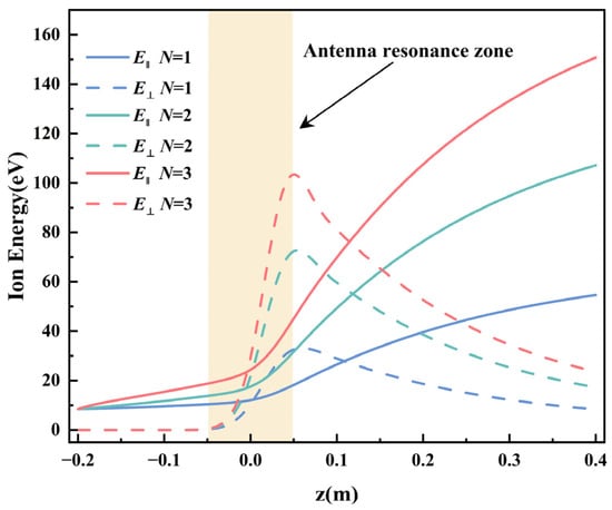
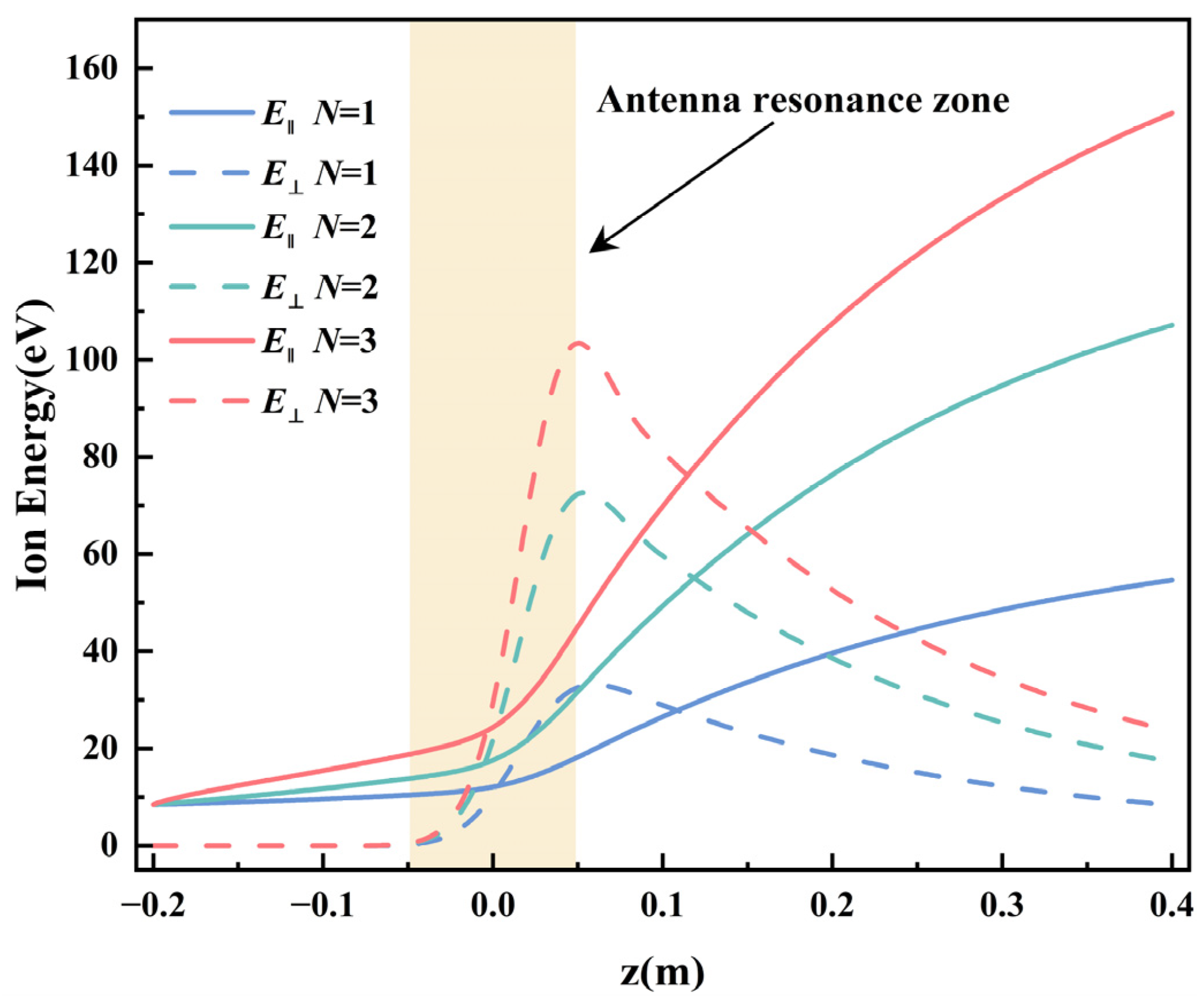
Figure 1 shows the result by solving Equations (1)–(9), and Table 1 provides the initial values of the simulation parameters. It qualitatively illustrates the evolutionary trajectories of the perpendicular kinetic energy and axial kinetic energy for , , and ions. The entire transport process can be distinctly divided into two physical stages.
Figure 1.
Variations in axial (solid lines) and perpendicular (dashed lines) kinetic energies of ions with different charge states (N = 1, 2, 3) after the ion cyclotron resonance heating (ICRH) phase, obtained by solving Equations (1)–(9).
Table 1.
Simulation Parameters.
The first is the wave-induced ICRH stage within the antenna resonance zone. In this region, the ions satisfy the local ICRH condition, and their perpendicular kinetic energy experiences a dramatic nonlinear surge. Because the wave–particle energy coupling rate is highly dependent on the ion charge number, the high-charge-state ions (N = 3) exhibit a profound nonlinear energy absorption advantage, resulting in a peak perpendicular kinetic energy that far exceeds that of the low-charge-state ions (N = 1).
The subsequent stage is the adiabatic expansion in the downstream magnetic nozzle. After the plasma exits the RF wave field, governed by the conservation of the adiabatic magnetic moment within the divergent background magnetic field, the perpendicular kinetic energy of the ions begins to attenuate and is converted into axial kinetic energy .
Figure 1 demonstrates that for a given propellant, high-charge-state ions achieve greater velocity gains during ICRH by solving. Mechanistically, at a given cyclotron wave frequency, a lighter propellant paired with a higher charge state lowers the background magnetic field threshold required for cyclotron resonance. Consequently, this work proposes a novel propulsion scheme using a light propellant, targeting high-charge-state ions as the primary vehicle for energy coupling during the ICRH stage.
3. Experimental Setup
3.1. Design of the Low-Magnetic-Field VASIMR Thruster
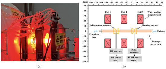
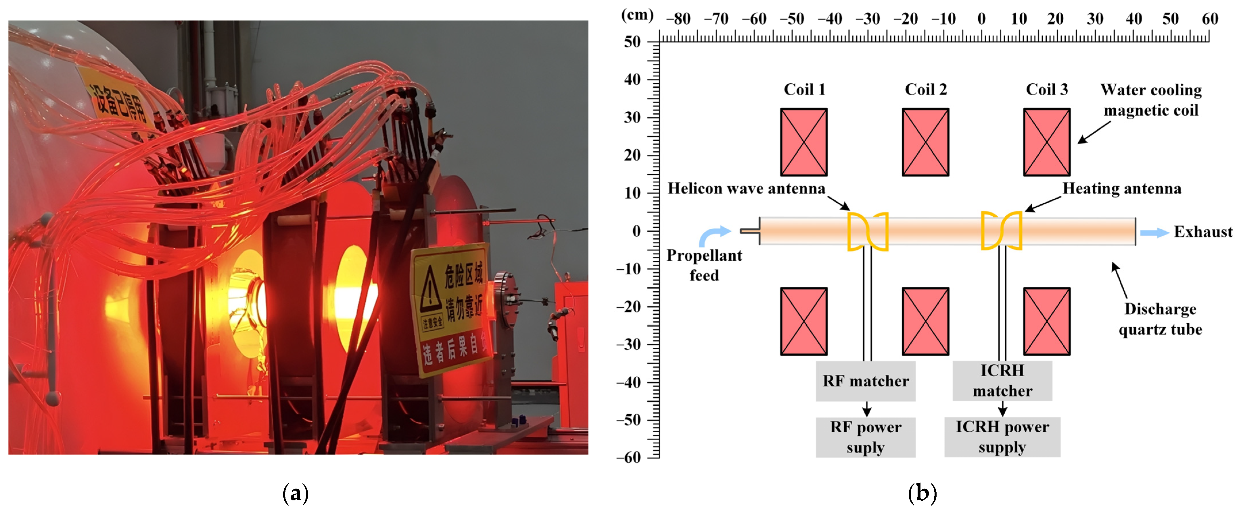
Figure 2 presents the photograph and schematic diagram of the thruster. The discharge chamber is a transparent quartz glass tube measuring 100 cm in length and 7 cm in diameter, with a wall thickness of 0.5 cm. The background pressure within the vacuum chamber is maintained at 1 × 10⁻² Pa.
Figure 2.
(a) shows the photograph of the thruster hardware used for testing; (b) shows the internal cutaway view of the thruster. In (b), axial origin is defined at the propellant inlet-side edge of the ICRH antenna, with the upstream as negative and downstream as positive.
The background magnetic field is generated by three identical water-cooled electromagnetic coils. Each coil consists of 264 turns of wire, featuring a casing with an inner diameter of 30 cm, an outer diameter of 65 cm, and an axial thickness of 12 cm. The spacing between adjacent coils is maintained at 20 cm. Each coil is independently driven by an adjustable DC power supply with an output range of 0–80 V and 0–300 A. Furthermore, integrated water-cooling channels are utilized to effectively mitigate the temperature rise caused by Joule heating. The peak magnetic field strength produced by this coil assembly is approximately 0.3 T, falling within the low-magnetic-field regime compared to conventional VASIMR thrusters.
The pre-ionization antenna adopts a Shoji right-hand helical configuration [29] and is powered by a 13.56 MHz RF power supply. This supply features an output power range of 0–5 kW with a tuning resolution of 1 W, and is equipped with an automatic impedance matching network. The ICRH antenna employs a Shoji left-hand helical configuration, connected to a 392 kHz intermediate-frequency ICRH power supply. This unit provides an output power range of 2.5–5 kW with a tuning resolution of 100 W, and utilizes a fixed matching network.
The mass flow controller operates within a range of 0–2000 sccm with a control resolution of 1 sccm. Given the relatively low background magnetic field, the light gas Ne is selected as the propellant for the experiments. Based on the analysis in Section 2, higher ion charge states yield greater velocity gains during ICRH while lowering the required resonance magnetic field. However, limited by the available ionization power, the abundance of higher charge states is extremely low, rendering them insufficient for generating effective thrust. To balance velocity gain and ion abundance, this study sets the magnetic field to match the resonance threshold of Ne2+, thereby optimizing performance within a low magnetic field architecture.
3.2. Measurement Instruments
The axial magnetic field strength was measured using a Lake Shore Model 425 Gaussmeter. This instrument features a measurement range from 350 mG to 350 kG, a DC resolution of 43/4 digits, a frequency range from DC to 10 kHz, and a basic DC accuracy of ±0.20%.
The ion energy distribution function (IEDF) and relative density were measured using a Retarding Potential Analyzer (RPA) manufactured by Impedans Ltd. The instrument features a maximum measurable energy of 2500 eV with an ion energy resolution of 1 eV, and was positioned 15 cm downstream from the discharge chamber nozzle.
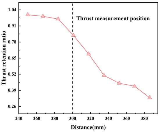
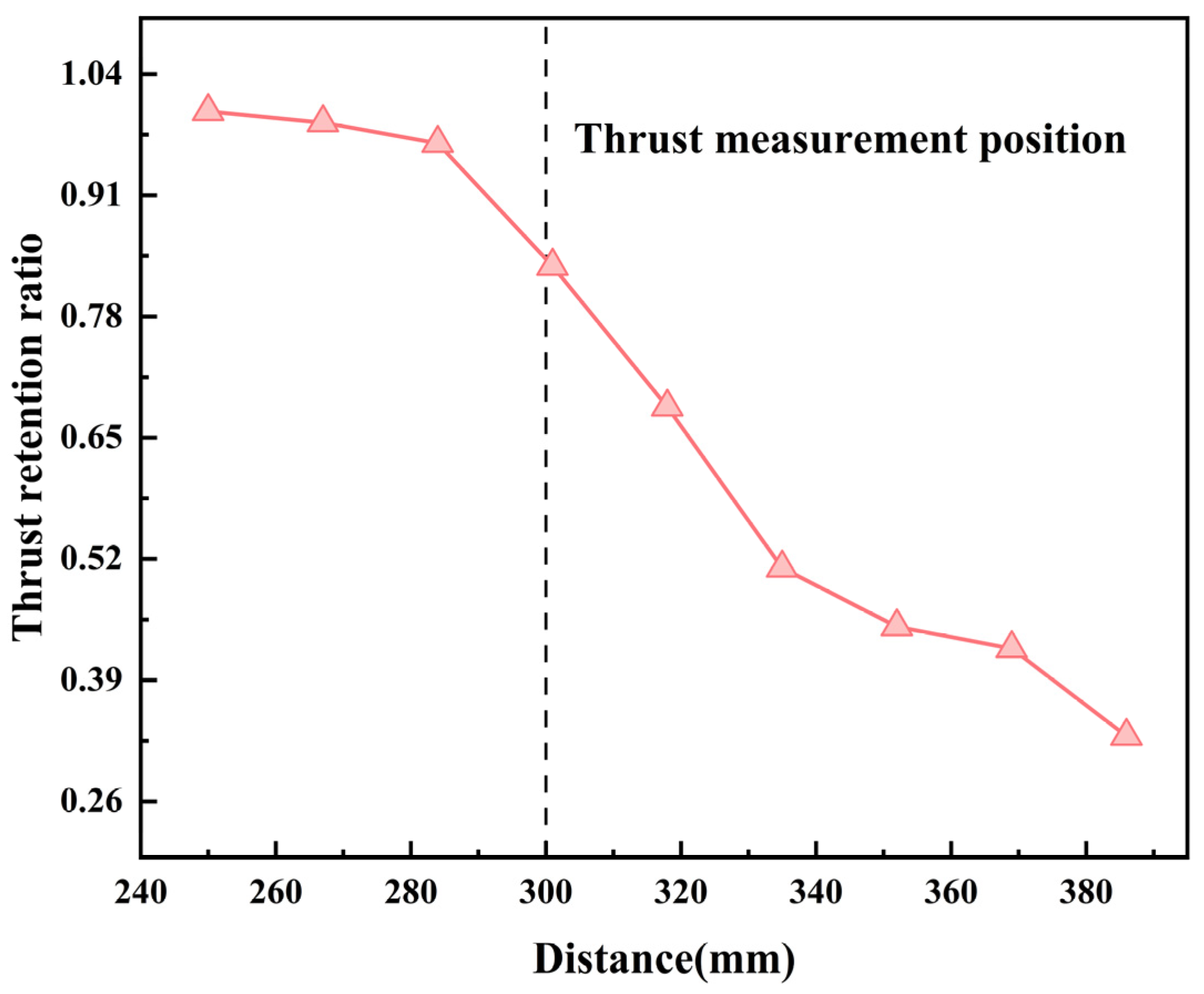
The thrust measurement system primarily consists of four symmetrically arranged rigid pendulum arms, a target platform, and a fixed base. The relative measurement uncertainty of this setup is 1.132%, and the position-dependent thrust attenuation factors are illustrated in Figure 3; the dashed line denotes the measurement location. In this study, to prevent damage to the target surface from prolonged plasma bombardment, the device was positioned approximately 30 cm downstream of the thruster nozzle. At this specific location, the corresponding thrust attenuation factor is approximately 0.834, meaning the measured value represents 83.4% of the actual thrust at the nozzle exit. Although the measured thrust is systematically underestimated due to this spatial attenuation, the factor applies uniformly to all measurements at this location; consequently, the normalized ratios and relative trends among different data sets remain completely unaffected.
Figure 3.
Variation in the thrust retention ratio with the distance. The dashed line denotes the measurement location.
4. Results and Discussion
4.1. The Phenomena of ICRH
The occurrence of ion resonance can be identified by two key indicators: the variation in ion energy and the change in plasma brightness. For ion cyclotron resonance to occur, the background magnetic field strength , the wave frequency emitted by the heating antenna, and the ion cyclotron frequency must satisfy the following condition:
In this study, the wave frequency emitted by the heating antenna is fixed. Therefore, to induce ion cyclotron resonance, the background magnetic field beneath the antenna must be controlled so that the ion cyclotron frequency approaches as closely as possible. Given the fixed heating frequency, the required resonant magnetic field for Ne2+ corresponds to 0.258 T.
This study experimentally investigates the ion energy distributions and plasma luminosity changes in the plume, specifically contrasting the Neon ion resonant and non-resonant states. During these tests, the operating conditions were maintained at a 1000 sccm mass flow rate, 1900 W of pre-ionization power, and 2.5 kW of ICRH power.
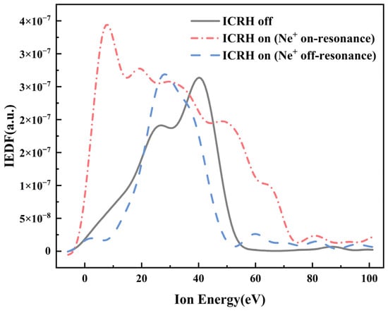
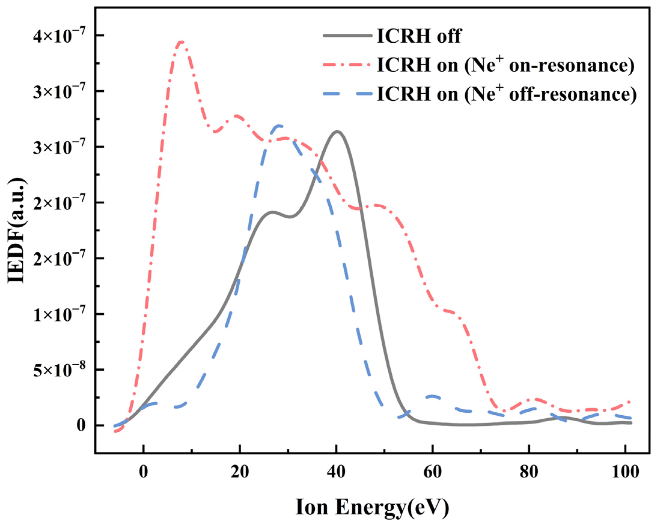
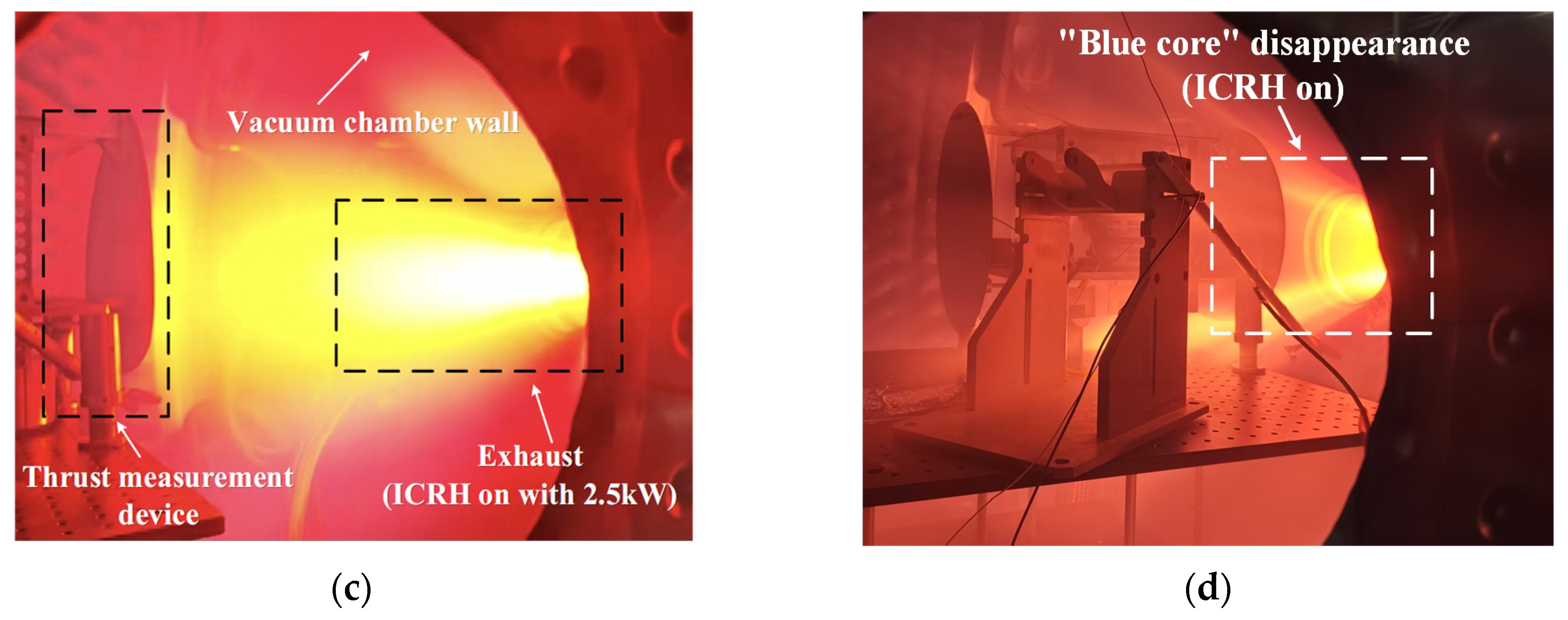
Figure 4 shows that when the Neon ion (Ne2+) resonance condition is not satisfied, the application of heating causes the IEDF to shift toward lower energies, with a noticeable reduction in the integrated area under the curve compared to the state prior to ICRH startup. Consequently, as shown in Figure 5d, rather than increasing, both the total ion energy and density experience a decline. Visually, the “blue core” dissipates noticeably, with no significant increase observed in the overall plume luminosity.
Figure 4.
The ion energy distribution function (IEDF) measured by the Retarding Potential Analyzer (RPA). When the Neon ion (Ne2+) resonance condition is not satisfied, the IEDF shifts toward the low-energy regime, with its envelope area decreasing relative to the baseline of ICRH off. Conversely, when the condition is satisfied, the IEDF broadens toward both the low- and high-energy regime, with its envelope area increasing relative to the baseline of ICRH off.
Figure 5.
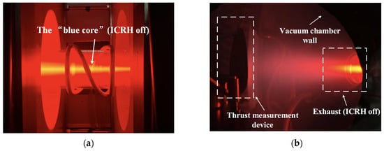
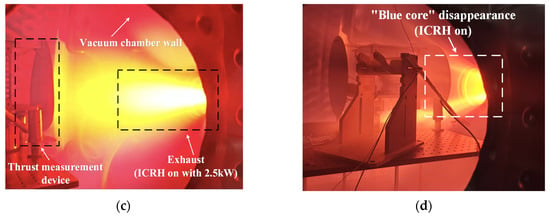
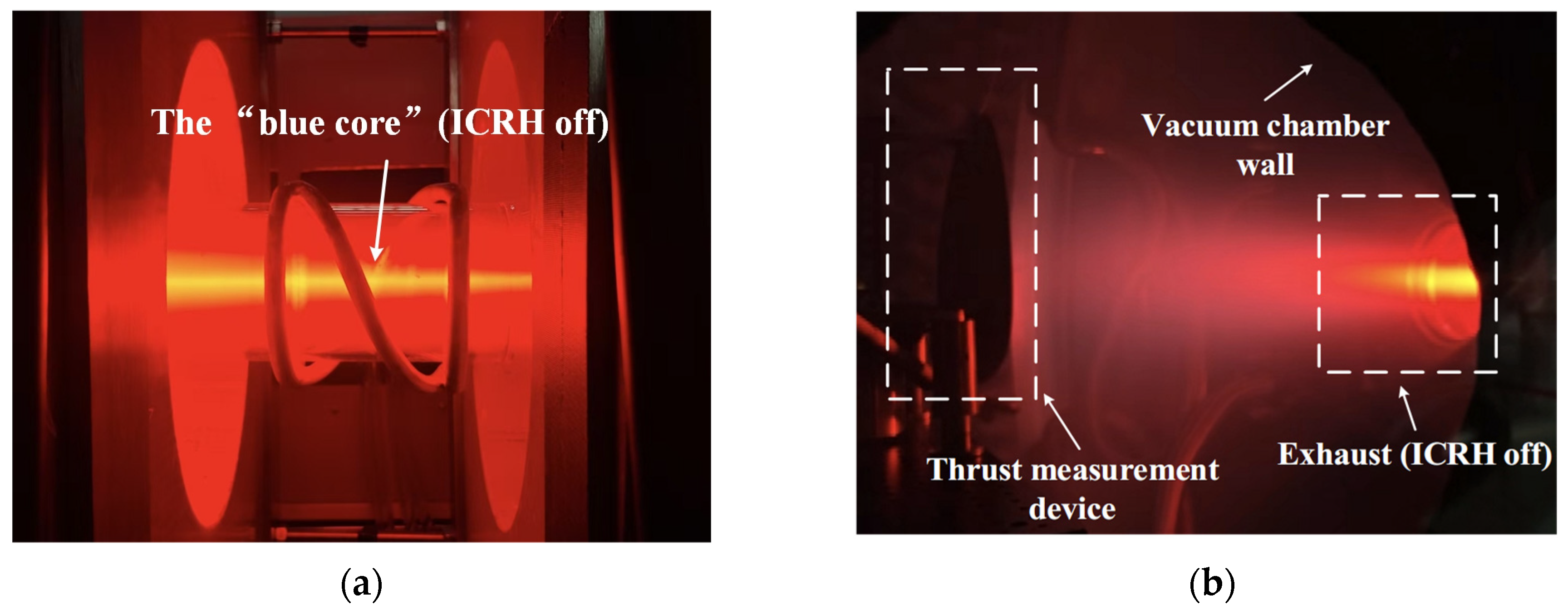
(a) The phenomena of the “blue core” prior to ICRH startup; (b) photograph of the plume region prior to ICRH startup; (c) photograph of the plume region after ICRH startup when the magnetic field strength in the resonance zone matches the required field for Neon ion (Ne2+) cyclotron resonance, showing a significant increase in luminosity; (d) when the magnetic field is insufficient to satisfy the Neon ion (Ne2+) resonance condition, the plume brightness exhibits no significant enhancement, and the “blue core” disappear.
As shown in Figure 4, when the Neon ion (Ne2+) resonance condition is satisfied, the corresponding IEDF envelope enlarges significantly, broadening into both the low-energy and high-energy regimes. Phenomenologically, as shown in Figure 5c, the “blue core” evolves into a more intense plume, accompanied by a marked increase in the brightness of the plume region.
4.2. Effect of Pre-Ionization Power on Thrust Performance
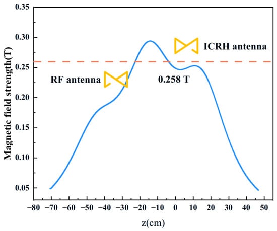
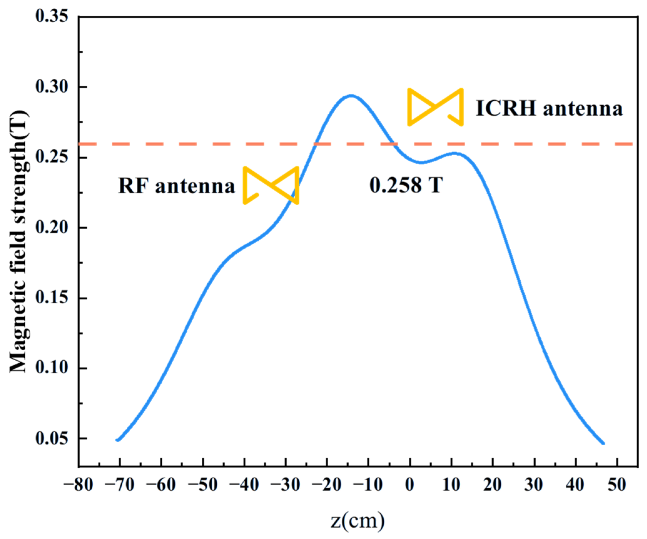
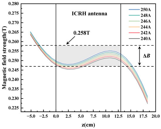
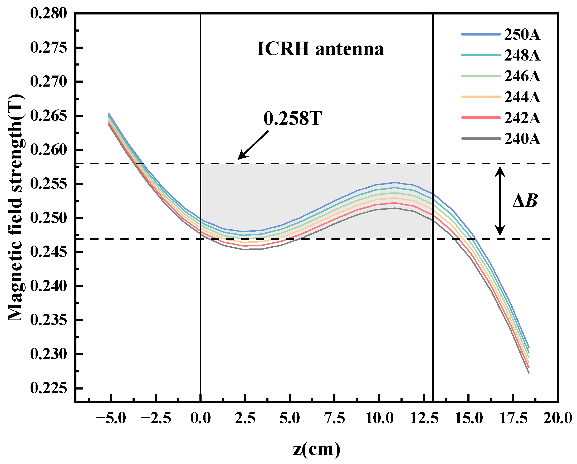
Experiments were conducted to investigate the effect of pre-ionization power on the thrust performance of the thruster. During the experiments, plume ion energy distributions and thrust were measured across a power range of 1400–2000 W with a 100 W step, while the propellant flow rate and ICRH power were fixed at 1000 sccm and 2.5 kW, respectively. The axial magnetic field configuration is illustrated in Figure 6. At a fixed ICRH frequency of 392 kHz, Equation (11) dictates a resonance field of 0.258 T for Neon ion (Ne2+). The magnetic field beneath the antenna was set slightly below this value; the rationale for this sub-theoretical configuration is detailed in Section 4.4.
Figure 6.
Axial magnetic field distribution of low-magnetic-field Variable Specific Impulse Magnetoplasma Rocket (VASIMR) (solid line), the dashed line denotes the resonant field strength for Neon ion (Ne2+) at an ICRH frequency of 392 kHz.
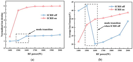
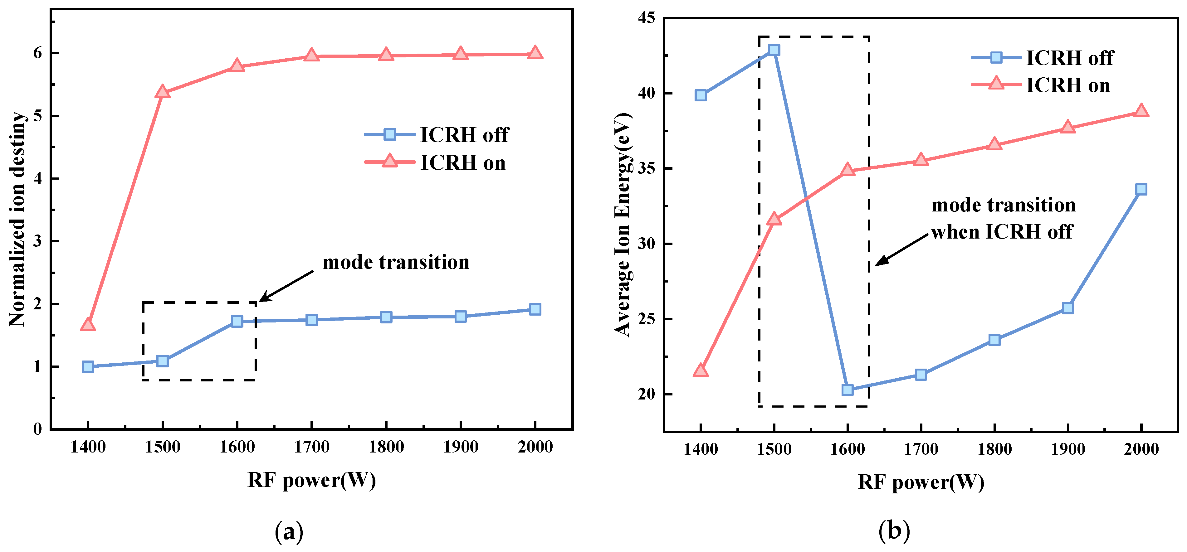
Figure 7a illustrates the evolutionary trend of the ion density as a function of pre-ionization power. The results indicate that, regardless of whether the ICRH mechanism is applied, the ion density continuously increases with the elevation in pre-ionization power and ultimately reaches saturation. Notably, at a constant pre-ionization power, the introduction of the ICRH mechanism substantially elevates the ion density level. Compared to the baseline, the maximum increase in ion density is approximately 1.9-fold prior to ICRH activation, whereas the density is boosted by up to roughly 6-fold following ICRH activation.
Figure 7.
Variations in (a) normalized ion density and (b) average ion energy as a function of radio frequency (RF) power ranging from 1400 to 2000 W. In (a), the density is normalized to the baseline value obtained at a 1400 W pre-ionization power, and 1000 sccm flow rate before ICRH ignition.
Furthermore, Figure 7a reveals a pronounced density jump phenomenon prior to ICRH activation as the pre-ionization power is increased from 1500 W to 1600 W. Within this specific interval, the plasma density leaps by a factor of approximately 1.6. This observation is consistent with findings reported in Reference [30] and can be attributed to the transition of discharge modes during the helicon wave stage.
Figure 7b displays the evolution of average ion energy versus pre-ionization power. Prior to ICRH startup, a prominent drop in the average ion energy is observed within the 1500–1600 W range, after which it resumes an upward trend. This sharp energy reduction corresponds directly to the density jump before ICRH activated. Physically, the higher pre-ionization power induces a helicon sub-mode transition, reallocating the absorbed RF energy. The coupling focus of the pre-ionization energy shifts from ion acceleration to gas ionization. The resulting surge in the ionization rate causes a spike in ion density, which dilutes the energy allocated per particle and manifests as a decrease in the mean ion energy.
After ICRH startup, the average ion energy grows continuously with increasing pre-ionization power. Notably, at lower powers, the mean energy is lower than that before ICRH activation. Specifically, at 1400 W and 1500 W, ICRH ignition triggers a 1.6-fold and 5.4-fold increase in ion density, respectively. This massive density growth leads to a strong energy dilution effect, keeping the mean energy at a low level. As the post-ICRH ion density approaches saturation at higher pre-ionization powers, the energy allocation shifts from ionization back to ion acceleration, thereby enhancing the average ion energy.
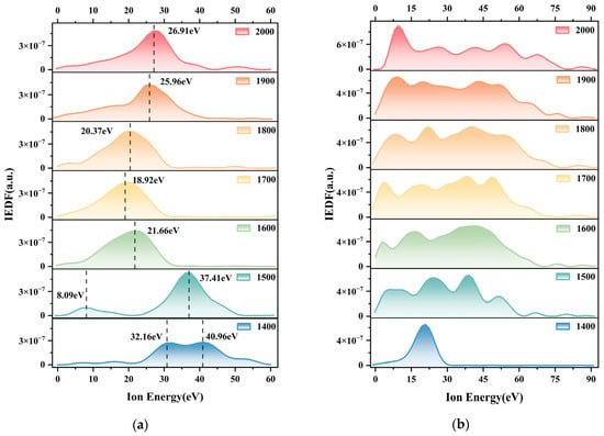
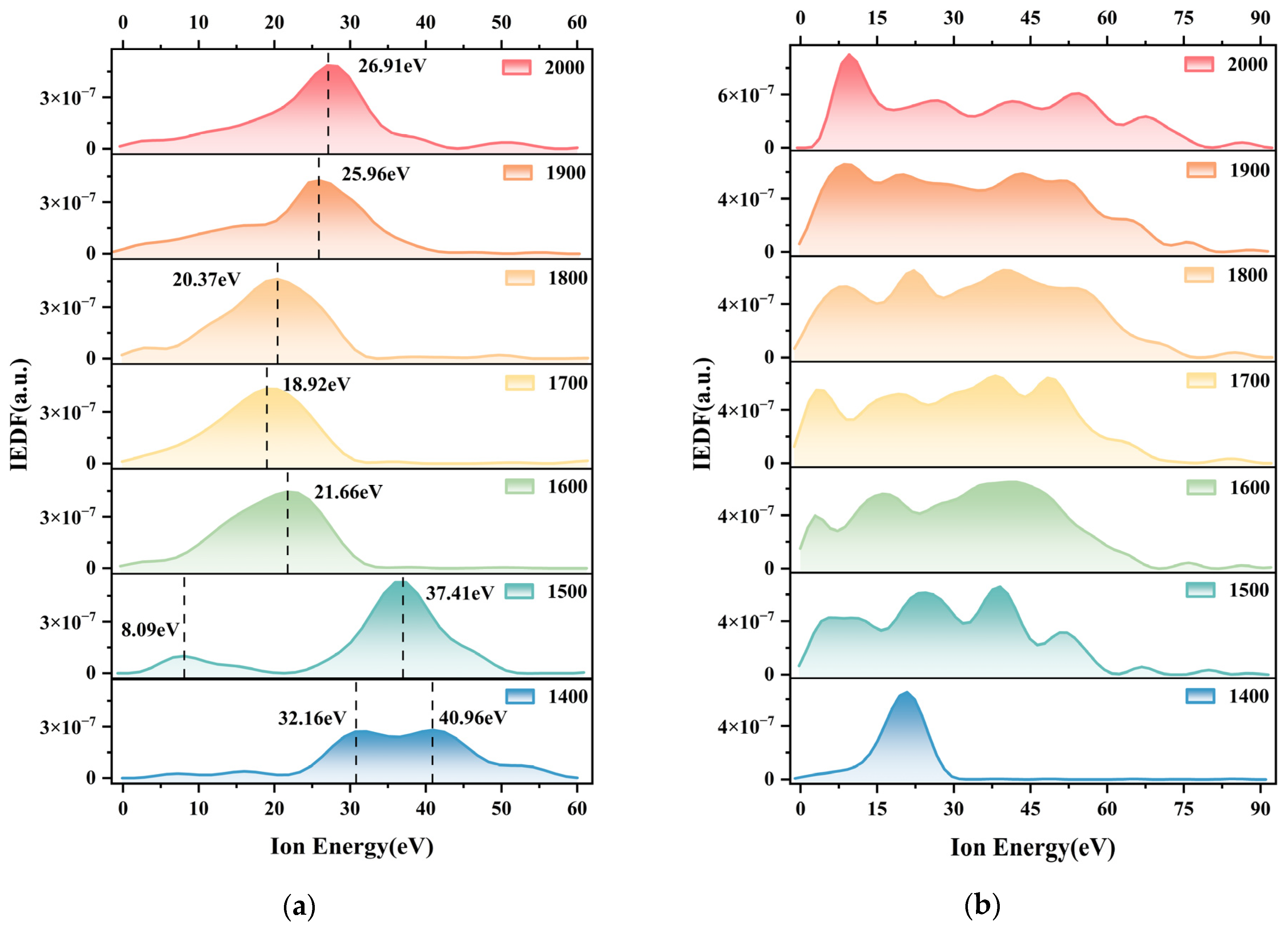
Figure 8 illustrates the evolution of the IEDF under different pre-ionization powers. As shown in Figure 8a, prior to ICRH startup, the distribution at 1400 W exhibits a distinct bimodal structure with a peak separation of 8.8 eV. At 1500 W, this bimodal feature intensifies; the peak separation widens to 29.32 eV, and the low-energy ion fraction increases. With a further power increase, the distribution first transitions into a unimodal profile heavily concentrated in the low-energy zone, and eventually shifts globally toward the high-energy region. This behavior directly reflects that higher pre-ionization powers channel more energy into gas ionization rather than ion acceleration.
Figure 8.
Variation in IEDF with RF Power measured by RPA, (a) shows the plume IEDF prior to ICRH startup, with the ion energy corresponding to the peak of the distribution labeled; (b) shows the plume IEDF after ICRH startup.
Figure 8b shows the variations in the IEDF after ICRH startup. Compared to the state without ICRH, the distribution at 1400 W shifts globally toward the lower-energy end. As the pre-ionization power increases, the distribution broadens simultaneously toward both low- and high-energy sides, with the high-energy extension being particularly prominent. This phenomenon is ascribed to the surge in Neon ion density at higher pre-ionization powers. The abundant Neon ions absorb most of the ICRH power, elevating the high-energy population and driving the evolution of the distribution curve.
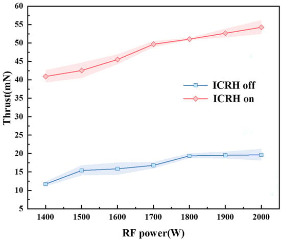
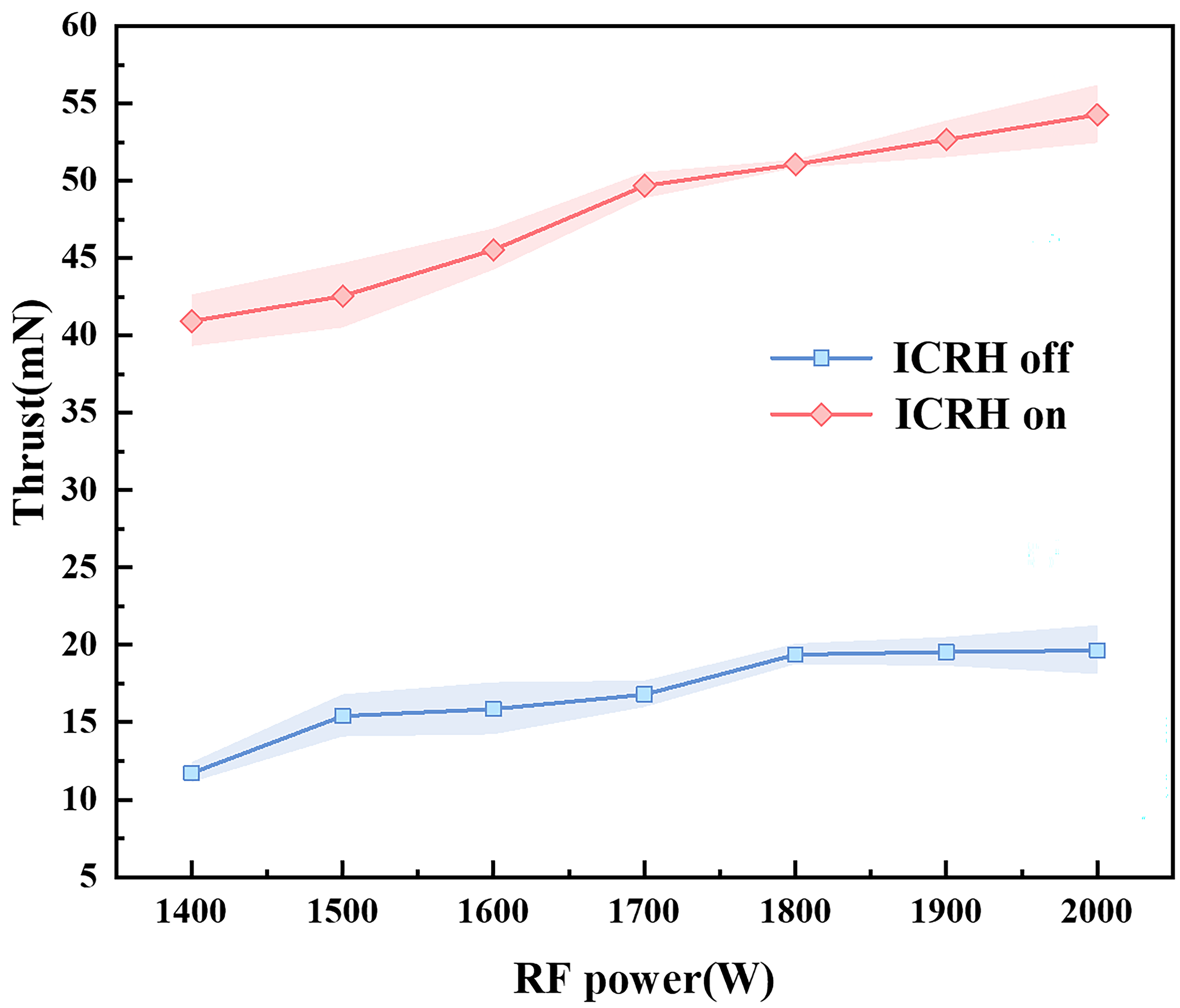
Figure 9 presents the measured thrust as a function of pre-ionization power. Notably, due to the structural constraints of the vacuum chamber and the thruster, the thrust stand was positioned 30 cm downstream of the thruster exit plane. Consequently, the measured values are significantly lower than the actual thrust, serving primarily as a qualitative reference. The results indicate that the thrust increases with pre-ionization power both before and after ICRH startup. Prior to ICRH activation, the thrust rises almost linearly from 11.73 mN to 19.65 mN. After ICRH startup, the thrust increases progressively from 40.94 mN to 54.28 mN across the same power range, maintaining a strong linear trend. Compared to the pre-ICRH stage, the average thrust increment is 31.19 mN for each 100 W increase in pre-ionization power.
Figure 9.
Variation in thrust with RF power from 1400 to 2000 W. Blue line: prior to ICRH startup; red line: after ICRH startup.
4.3. Impact of ICRH Power on Thrust Improvement
Experiments were further extended to investigate the effect of ICRH power on the thrust enhancement of the thruster, with the pre-ionization power and flow rate fixed at 1900 W and 1000 sccm, respectively, ion energies and thrust profiles were characterized at discrete ICRH powers of 2.5, 3.0, 3.5, and 4.0 kW.
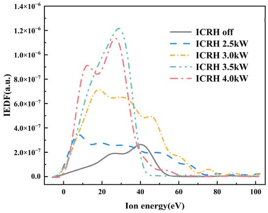
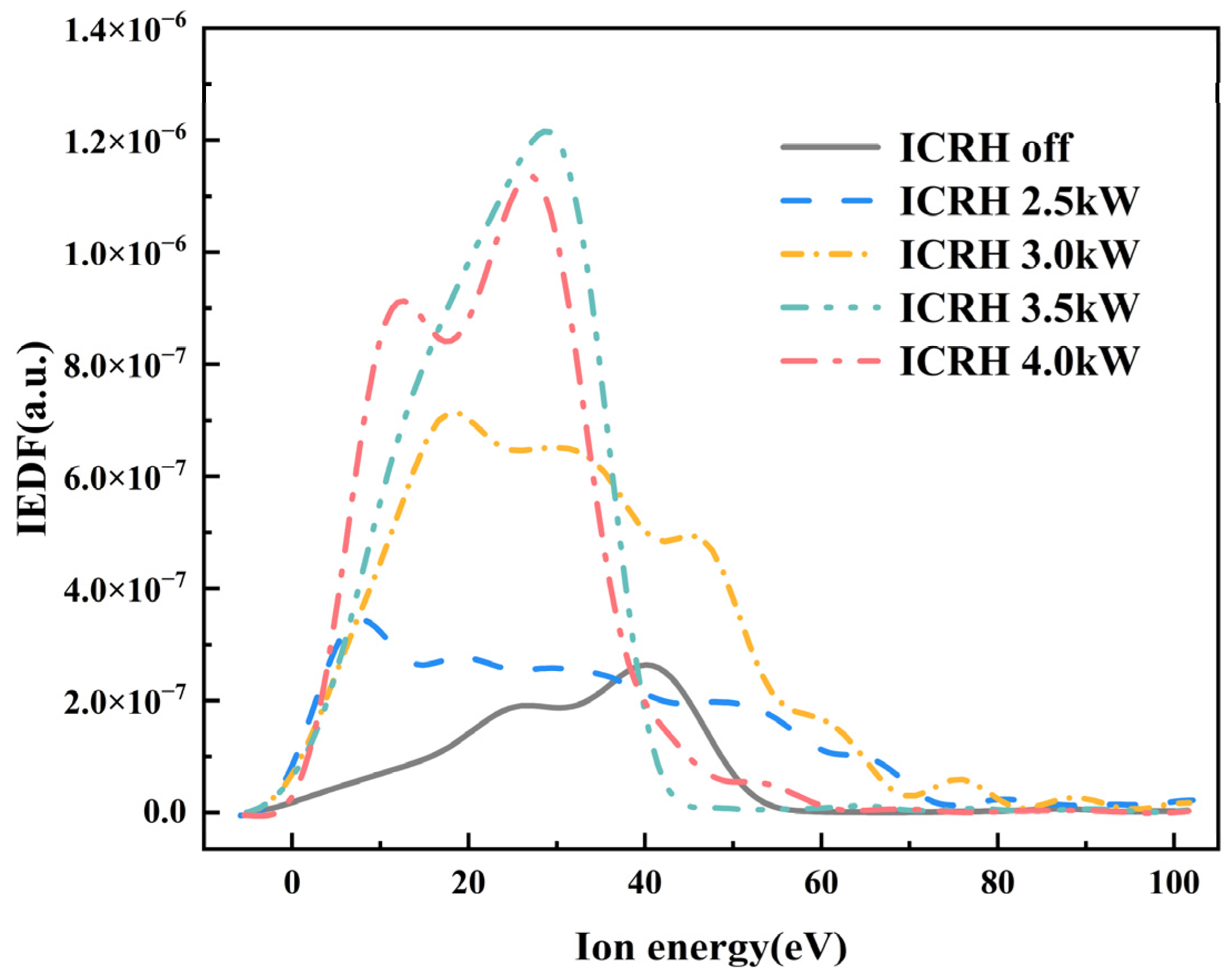
The ion energy distribution curves in the thruster plume region are shown in Figure 10. The results indicate that at an ICRH power of 2.5 kW, compared to the ICRH off state, the ion energy distribution curve of the plume broadens simultaneously in both the low- and high-energy regimes. As the ICRH power is subsequently increased to 3 kW, the envelope area of the distribution curve becomes larger, demonstrating that the total kinetic energy of the ions continuously expands during the ramp-up of ICRH power from 0 kW to 3 kW. As the ICRH power further escalates to 3.5 kW and 4 kW, the energy distribution undergoes another transition. Distinct from the behaviors observed at 2.5 kW and 3 kW, when the ICRH power is elevated to 3.5 kW and 4 kW, the proportion of ions in the high-energy regime decreases, whereas a corresponding increase is observed in the low-energy regime.
Figure 10.
Variation in IEDF with ICRH power measured by RPA.
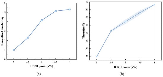
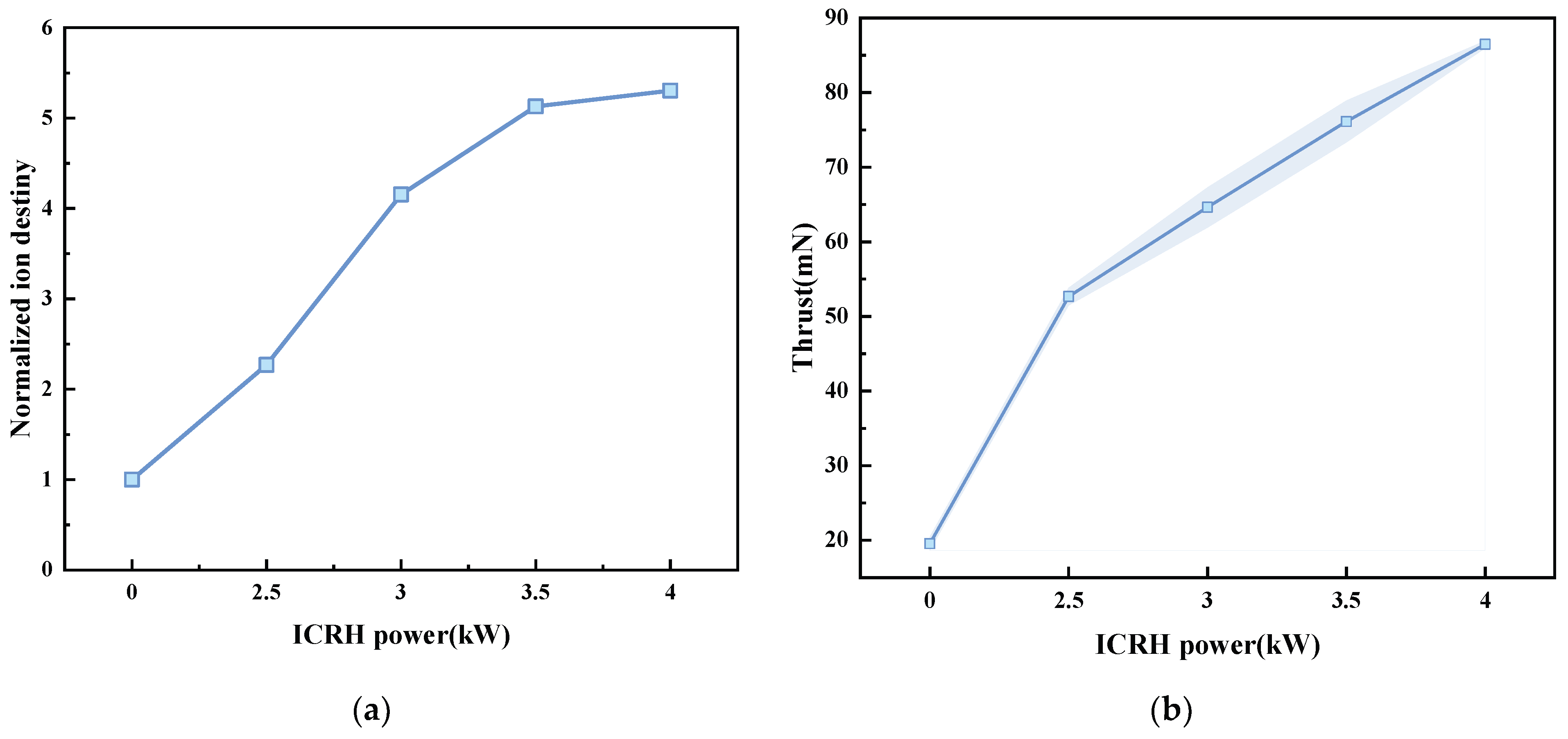
Figure 11a illustrates the relative ion density corresponding to each ICRH power level. The results demonstrate that the relative ion density exhibits an upward trend with increasing ICRH power. Specifically, at an ICRH power of 2.5 kW, the ion density directly reaches 2.3 times the baseline level recorded before ICRH activation, when the ICRH power is elevated to 4 kW, the ion density increases to 5.3 times the baseline level.
Figure 11.
Variations in (a) normalized ion density and (b) thrust as a function of ICRH power ranging from 1400 to 2000 W. In (a), the density is normalized to the baseline value obtained at a 1900 W pre-ionization power, and 1000 sccm flow rate before ICRH ignition.
These findings indicate that, on the one hand, the injection of ICRH power increases the ion density, which is visually reflected in Figure 8 as the substantial broadening of the population of low-energy ions with increasing power. On the other hand, the injection of ICRH power directly drives a kinetic energy leap in Neon ion, corresponding to the high-energy component in Figure 8 that continuously extends outward as the power scales up.
The variation in the thruster’s thrust as a function of ICRH power is presented in Figure 11b. The results show that the injection of ICRH power yields a remarkable enhancement in thrust performance. Compared to the operation prior to ICRH activation, the initiation of a 2.5 kW ICRH provides an immediate thrust gain of 33.12 mN. During the ramp-up of ICRH power from 2.5 kW to 4 kW, the thrust increases almost linearly from 55 mN to 86 mN, exhibiting a nearly linear variation trend throughout the process. The injection of ICRH power substantially elevates both the overall ion energy level and the macro-thrust, serving as a direct manifestation that Neon ion acts as the primary absorption species for ICRH energy. This further validates the technical feasibility of the VASIMR light-propellant propulsion scheme under weak background magnetic fields.
4.4. Effect of Magnetic Field Topology Within the Resonance Zone on ICRH Efficiency
Under realistic conditions, ions enter the region beneath the ICRH antenna with a parallel velocity . Given that the parallel wavenumber of the incident wave is , the frequency of the incident ICRH wave will experience a Doppler shift relative to the ions in the ion rest frame [31], expressed as follows:
Correspondingly, for a fixed incident wave frequency, the magnetic field strength required to induce ion cyclotron resonance is no longer a strictly single discrete value, which yields:
Consequently, when a Doppler shift occurs, the discrete resonance zone broadens into a finite resonance band:
Due to the Doppler shift effect, the actual cyclotron resonance magnetic field required for ions at a given cyclotron wave frequency falls below the theoretically calculated value. Furthermore, the three-coil configuration complicates the magnetic field regulation within the resonance region. Consequently, the effective spatial volume satisfying the resonance band varies significantly under different excitation current setups, which ultimately impacts the ICRH performance.
The experiment adjusts the current in coil 3 to modulate the magnetic field topology within the resonance zone. Figure 12 illustrates the axial magnetic field topologies within the resonance zone as the current in coil 3 varies from 240 A to 250 A, the diagram qualitatively delineates the variations in the resonant magnetic field strength induced by the Doppler shift. When the current in coil 3 is set to 240 A, the spatial coverage of the Doppler-shifted resonance band beneath the ICRH antenna is relatively small. As the current in coil 3 continuously increases, the region beneath the ICRH antenna capable of overlapping with the resonance band gradually expands. Furthermore, the constructive superposition of the magnetic fields generated by coil 2 and coil 3 correspondingly elevates the peak value of the magnetic field topology in this region.
Figure 12.
Variation in the axial magnetic field topology beneath the ICRH antenna with coil 3 current from 240 to 250 A measured by Gauss meter.
Experimental investigations were subsequently conducted to evaluate the effect of the resonance-zone magnetic field topology on the thrust performance of the thruster. The operational parameters were configured with a propellant flow rate of 1000 sccm, a pre-ionization power of 1900 W, and an ICRH power of 2.5 kW. Under these identical conditions, the magnetic field topologies at various currents of coil 3, along with their corresponding macroscopic thrust and relative ion density, were systematically measured.
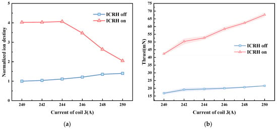
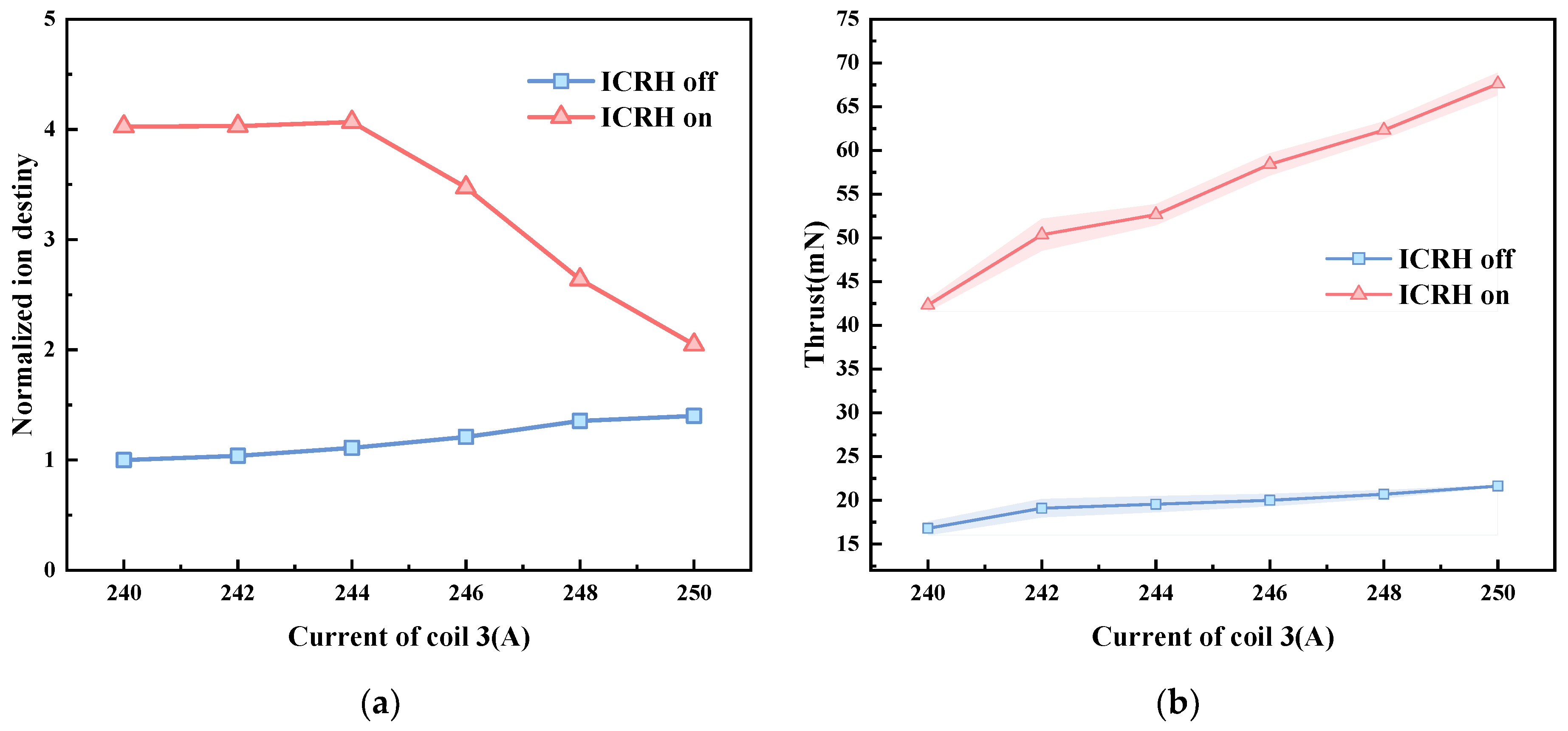
Figure 13a illustrates the variation trend of the relative ion density as a function of the increasing current in coil 3. The results indicate that prior to ICRH activation, the ion density exhibits an upward trend with the increment in the current in coil 3. Following ICRH activation, however, the ion density presents a trend of initially increasing and subsequently decreasing as the current in coil 3 increases.
Figure 13.
Variations in (a) normalized ion density and (b) average ion energy as a function of Current of coil 3 ranging from 240 to 250 A. In (a), the density is normalized to the baseline value obtained at a 1900 W pre-ionization power, 240 A current in coil 3, and 1000 sccm flow rate before ICRH ignition.
The evolution of ion density after ICRH activation is likewise closely related to the extent of the resonance band. As derived from Equation (5), the relation between the ion density and the ion velocity in the plume region satisfies the following expression:
In the experiment, when the current in coil 3 is below 244 A, the resonance band remains narrow, allowing ions to rapidly traverse the resonance zone, which leads to insufficient absorption of the ICRH power. As the current in coil 3 continues to increase, the resonance band gradually broadens, thereby extending the transit time of ions through the resonance band. This enables a more sufficient absorption of the ICRH power and yields a larger increment in kinetic energy. According to Equation (1), the ion density will consequently undergo attenuation.
The variation trend of the thruster’s thrust as a function of the current in coil 3 is illustrated in Figure 13b. Prior to ICRH activation, the system thrust exhibits a monotonically increasing trend with the increment in the current in coil 3, as the current rises from 240 A to 250 A, the thrust increases slowly from 16.79 mN to 21.62 mN. This phenomenon has been previously documented in literature [32,33]. It is attributed to the fact that a stronger magnetic field downstream of the pre-ionization antenna leads to more controllable divergence of the magnetic field lines. The reduction in the Larmor radius allows ions to be better confined along the magnetic field lines, thereby decreasing radial wall losses and subsequently enhancing both the ion density and the thrust.
After ICRH activation, the thrust increases as the Coil 3 current rises, growing from 42.32 mN at 240 A to 67.62 mN at 250 A. Meanwhile, the thrust increment relative to the unheated state exhibits a monotonic growth. When the current increases from 240 to 250 A, the net thrust gain jumps from 25.53 mN to 46 mN.
Mechanistically, this thrust evolution stems from resonance zone modifications. Increasing the Coil 3 current strengthens the magnetic field beneath the antenna, broadening the coverage and expanding the resonance band. Consequently, ions experience a longer transit time across the resonance zone. They absorb more RF energy, which significantly boosts their angular kinetic energy. This explains the pronounced thrust variations post-ICRH startup. Furthermore, it indicates that given constant pre-ionization and ICRH powers, maximizing the resonance band directly improves the thruster’s thrust-to-power ratio.
5. Conclusions
This study evaluates the performance of a weak-magnetic-field VASIMR thruster. We measured the ion energy and thrust under various operating conditions. The results show that at a fixed flow rate and ICRH power, increasing the pre-ionization power boosts the ion density by up to six times before it saturates. More Neon ions, which absorb the ICRH power, effectively increase the thrust. Specifically, every 100 W increase in pre-ionization power adds an average of 2.2 mN to the thrust.
ICRH power injection significantly increases the total thrust. This confirms the feasibility of using Neon ion as a light propellant. The ICRH power plays a dual role. First, it increases the ionization rate and plasma density, which indirectly boosts the thrust. Second, Neon ions directly absorb the ICRH power and convert it into thrust. On average, every 500 W of ICRH power generates a 10.3 mN thrust gain.
Optimizing the magnetic field in the resonance zone is key to improving performance. Because of the Doppler shift, a broader resonance band provides a larger space for wave–particle interaction. This allows Neon ions to absorb energy more efficiently, which directly increases the thrust. By optimizing the magnetic field, we achieved a maximum thrust gain of 25.3 mN.
Due to experimental limitations, although the experiments were conducted under conditions satisfying the Ne2+ resonance and the resonance phenomenon was observed, it remains unclear at the microscopic level whether the observed resonance is indeed caused by the absorption of ICRH power by Ne2+. Therefore, future work will focus on identifying the ion species responsible for the resonance in order to further elucidate the physical mechanism of the resonance phenomenon under low magnetic fields.
In conclusion, this study verifies the feasibility of using high-charge-state light ions for VASIMR under a weak magnetic field. This provides a foundation for future lightweight VASIMR designs. Generating competitive thrust in conventional VASIMR architectures requires prohibitively high RF power and strong magnetic fields, bottlenecking their deep-space application due to reliance on oversized solar arrays or unproven space nuclear reactors. This study directly tackles this limitation by drastically lowering the background magnetic field required for resonance. This approach effectively slashes parasitic power losses and alleviates the mass burden of the magnetic and thermal systems, establishing a rigorous basis for VASIMR’s technological readiness under current space power constraints. Future studies can focus on architectural optimization and system-level power management strategies to pave the way for its practical spaceborne applications.
Author Contributions
Conceptualization, Y.W., X.S. and H.G.; methodology, Y.W., X.S. and H.G.; software, Y.W.; validation, Y.W.; formal analysis Y.W.; investigation, Y.W., H.C. and Y.C.; resources, H.C.; data curation, Y.W.; writing—original draft preparation, Y.W.; writing—review and editing, Y.W., W.L. and H.G.; visualization, Y.W.; supervision, X.S. and H.G.; project administration, Y.W., X.S. and H.G.; funding acquisition, X.S., H.G. and J.L. All authors have read and agreed to the published version of the manuscript.
Funding
This research received no external funding.
Data Availability Statement
The data involved in this study are subject to confidentiality agreements and therefore cannot be made publicly available. Inquiries regarding the data may be directed to the corresponding author; however, any data release remains subject to the applicable confidentiality restrictions.
Conflicts of Interest
The authors declare no conflict of interest.
References
- Paissoni, C.A.; Viola, N.; Mammarella, M.; Andreussi, T.; Rossodivita, A.; Saccoccia, G. Deep Space Transportation Enhanced by 20 kW-Class Hall Thrusters. Acta Astronaut. 2020, 171, 83–96. [Google Scholar] [CrossRef] [Scilit]
- Levchenko, I.; Goebel, D.; Pedrini, D.; Albertoni, R.; Baranov, O.; Kronhaus, I.; Lev, D.; Walker, M.L.R.; Xu, S.; Bazaka, K. Recent Innovations to Advance Space Electric Propulsion Technologies. Prog. Aerosp. Sci. 2025, 152, 100900. [Google Scholar] [CrossRef] [Scilit]
- Magarotto, M.; Manente, M.; Trezzolani, F.; Pavarin, D. Numerical Model of a Helicon Plasma Thruster. IEEE Trans. Plasma Sci. 2020, 48, 835–844. [Google Scholar] [CrossRef] [Scilit]
- O’Reilly, D.; Herdrich, G.; Kavanagh, D.F. Electric Propulsion Methods for Small Satellites: A Review. Aerospace 2021, 8, 22. [Google Scholar] [CrossRef] [Scilit]
- Bering, E.; Chang-Diaz, F.; Squire, J.; Jacobson, V.; Brukardt, M.; Longmier, B. The VASIMR(TM) VX-100 Engine: Next Step to High Power Electric Propulsion. In Proceedings of the 46th AIAA Aerospace Sciences Meeting and Exhibit; American Institute of Aeronautics and Astronautics: Reno, NV, USA, 2008. [Google Scholar]
- Mazouffre, S. Electric Propulsion for Satellites and Spacecraft: Established Technologies and Novel Approaches. Plasma Sources Sci. Technol. 2016, 25, 033002. [Google Scholar] [CrossRef] [Scilit]
- Mercer, C.R.; McGuire, M.; Oleson, S.R. Solar Electric Propulsion Concepts for Human Space Exploration. In Proceedings of the AIAA SPACE 2015 Conference and Exposition; American Institute of Aeronautics and Astronautics: Pasadena, CA, USA, 2015. [Google Scholar]
- Carpenter, C.; Myers, R.; Hoskins, W.; Kimbrel, S. A Space Logistics System Based on Efficient In-Space Transportation. In Proceedings of the AIAA SPACE 2012 Conference & Exposition; American Institute of Aeronautics and Astronautics: Pasadena, CA, USA, 2012. [Google Scholar]
- Spores, R.; Monheiser, J.; Dempsey, B.P.; Wade, D.; Creel, K.; Jacobson, D.; Drummond, G. A Solar Electric Propulsion Cargo Vehicle to Support NASA Lunar Exploration Program. In Proceedings of the IEPC Paper No. IEPC-2005-320, 25th International Electric Propulsion Conference, Princeton, NJ, USA, 31 October–4 November 2005; Volume 31. [Google Scholar]
- Palac, D.; Horvat, G.; Jankovsky, R.; Shaltens, R.; Oleson, S. Shrinking the Solar System Nuclear Electric Propulsion Systems for Robotic and Human Exploration. In Proceedings of the 1st Space Exploration Conference: Continuing the Voyage of Discovery, Orlando, FL, USA, 30 January 2005; American Institute of Aeronautics and Astronautics: Reston, VA, USA, 2005. [Google Scholar]
- Díaz, F.R.C. The Vasimr Rocket. Sci. Am. 2000, 283, 90–97. [Google Scholar] [CrossRef] [Scilit]
- Glover, T.W. Principal VASIMR Results and Present Objectives. In Proceedings of the AIP Conference Proceedings; AIP: Albuquerque, NM, USA, 2005; Volume 746, pp. 976–982. [Google Scholar]
- Arefiev, A.V.; Breizman, B.N. Theoretical Components of the VASIMR Plasma Propulsion Concept. Phys. Plasmas 2004, 11, 2942–2949. [Google Scholar] [CrossRef] [Scilit]
- Nieto, J.C.; Del Valle, J.; Martınez, C.; Rivera, A.; Oguilve, J.; Olsen, C.S.; Giambusso, M.; Carter, M.D.; Squire, J.P.; Dıaz10, F.R.C. Vasimr® Vx-Cr Experiment: Status, Diagnostics and Plasma Plume Characterization. In Proceedings of the 33rd International Electric Propulsion Conference, Washington, DC, USA, 6–10 October 2013; pp. 6–10. [Google Scholar]
- Boswell, R.W.; Chen, F.F. Helicons-the Early Years. IEEE Trans. Plasma Sci. 1997, 25, 1229–1244. [Google Scholar] [CrossRef] [Scilit]
- Zhao, W.; Yang, X.; Cheng, M.; Li, X.; Lin, X.; Lei, Q. Effect of Ion Cyclotron Resonance on Single Superparticle Movement Using PIC–MCC Simulation. Plasma Sci. Technol. 2025, 27, 115504. [Google Scholar] [CrossRef] [Scilit]
- Wu, K.; Chen, Z.; Ren, J.; Wang, Y.; Zhang, G.; Wang, W.; Tang, H. A Review of Plasma Acceleration and Detachment Mechanisms in Propulsive Magnetic Nozzles. Phys. Plasmas 2025, 32, 040501. [Google Scholar] [CrossRef] [Scilit]
- Bering, E.; Longmier, B.; Ballenger, M.; Olsen, C.; Squire, J.; Chang Diaz, F. Performance Studies of the VASIMR® VX-200. In Proceedings of the 49th AIAA Aerospace Sciences Meeting Including the New Horizons Forum and Aerospace Exposition, Orlando, FL, USA, 4 January 2011; American Institute of Aeronautics and Astronautics: Reston, VA, USA, 2011. [Google Scholar]
- Longmier, B.W.; Squire, J.P.; Cassady, L.D.; Ballenger, M.G.; Carter, M.D.; Olsen, C.; Ilin, A.V.; Glover, T.W.; McCaskill, G.E.; Dıaz, F.C.; et al. VASIMR VX-200 Performance Measurements and Helicon Throttle Tables Using Argon and Krypton. In Proceedings of the 32nd International Electric Propulsion Conference, Wiesbaden, Germany, 11–15 September 2011. [Google Scholar]
- Squire, J.P.; Carter, M.D.; Chang Diaz, F.R.; Dean, L.; Giambusso, M.; Castro, J.; Del Valle, J. Advances in Duration Testing of the VASIMR® VX-200SSTM System. In Proceedings of the 52nd AIAA/SAE/ASEE Joint Propulsion Conference, Salt Lake City, UT, USA, 25 July 2016; American Institute of Aeronautics and Astronautics: Reston, VA, USA, 2016. [Google Scholar]
- Squire, J.P.; Carter, M.; Chang Diaz, F.R.; Corrigan, A.; Dean, L.; Farrias, J.; Giambusso, M.; McCaskill, G.; Yao, T. Steady-State Testing at 100 kW in the VASIMR® VX-200SS Project. In Proceedings of the AIAA Propulsion and Energy 2019 Forum, Indianapolis, IN, USA, 19 August 2019; American Institute of Aeronautics and Astronautics: Reston, VA, USA, 2019. [Google Scholar]
- Squire, J.P.; Díaz, F.R.C.; Glover, T.W.; Jacobson, V.T.; Chavers, D.G.; Bengtson, R.D.; Bering, E.A.; Boswell, R.W.; Goulding, R.H.; Light, M. Progress in Experimental Research of the Vasimr Engine. Fusion Sci. Technol. 2003, 43, 111–117. [Google Scholar] [CrossRef] [Scilit]
- Longmier, B.; Squire, J.; Olsen, C.; Cassady, L.; Ballenger, M.; Carter, M.; Ilin, A.; Glover, T.; McCaskill, G.; Chang Diaz, F.; et al. VASIMR® VX-200 Improved Throttling Range. In Proceedings of the 48th AIAA/ASME/SAE/ASEE Joint Propulsion Conference & Exhibit, Atlanta, GA, USA, 30 July 2012; American Institute of Aeronautics and Astronautics: Reston, VA, USA, 2012. [Google Scholar]
- Breizman, B.N.; Arefiev, A.V. Single-Pass Ion Cyclotron Resonance Absorption. Phys. Plasmas 2001, 8, 907–915. [Google Scholar] [CrossRef] [Scilit]
- Chen, F.F. Introduction to Plasma Physics and Controlled Fusion; Springer International Publishing: Cham, Switzerland, 2016. [Google Scholar]
- Griffiths, D.J. Introduction to Electrodynamics, 4th ed.; International ed.; Always Learning; Pearson: Boston, MA, USA, 2013. [Google Scholar]
- Davis, C.; Gilchrist, B.; Squire, J.; Chang Diaz, F. Density Measurements During Ion Cyclotron Heating in VASIMR. In Proceedings of the 40th AIAA/ASME/SAE/ASEE Joint Propulsion Conference and Exhibit, Fort Lauderdale, FL, USA, 11 July 2004; American Institute of Aeronautics and Astronautics: Reston, VA, USA, 2004. [Google Scholar]
- Zhang, T.; Xia, Z.; Zheng, B.; Zhang, H.; Ouyang, J.; Rattenbury, N. Effect of Mode Transition on Discharge Features and Power Coupling in the Source of a Helicon Plasma Thruster. Acta Astronaut. 2025, 236, 228–238. [Google Scholar] [CrossRef] [Scilit]
- Shinohara, S. Helicon High-Density Plasma Sources: Physics and Applications. Adv. Phys. X 2018, 3, 1420424. [Google Scholar] [CrossRef] [Scilit]
- Sun, B.; Zhang, Y.; Zhou, C.; Xia, G.; Lu, C.; Han, D. Influence Mechanism of Magnetic Field and Wave Modes on Helicon Plasma Thruster. AIAA J. 2023, 61, 5264–5276. [Google Scholar] [CrossRef] [Scilit]
- Ilin, A.; Chang Diaz, F.; Squire, J.; Carter, M. Plasma Heating Simulation in the VASIMR System. In Proceedings of the 43rd AIAA Aerospace Sciences Meeting and Exhibit, Reno, NV, USA, 10 January 2005; American Institute of Aeronautics and Astronautics: Reston, VA, USA, 2005. [Google Scholar]
- Takahashi, K.; Charles, C.; Boswell, R.; Ando, A. Effect of Magnetic and Physical Nozzles on Plasma Thruster Performance. Plasma Sources Sci. Technol. 2014, 23, 044004. [Google Scholar] [CrossRef] [Scilit]
- Takahashi, K.; Komuro, A.; Ando, A. Operating a Magnetic Nozzle Helicon Thruster with Strong Magnetic Field. Phys. Plasmas 2016, 23, 033505. [Google Scholar] [CrossRef] [Scilit]

Disclaimer/Publisher’s Note: The statements, opinions and data contained in all publications are solely those of the individual author(s) and contributor(s) and not of MDPI and/or the editor(s). MDPI and/or the editor(s) disclaim responsibility for any injury to people or property resulting from any ideas, methods, instructions or products referred to in the content. |
© 2026 by the authors. Licensee MDPI, Basel, Switzerland. This article is an open access article distributed under the terms and conditions of the Creative Commons Attribution (CC BY) license.