


Abstract
The desire to use space in the most rational and efficient way to address contemporary challenges leads to the necessity of creating multi-purpose space missions capable of solving a wide range of diverse tasks. This creates a demand for propulsion systems that can provide high maneuverability for modern and future spacecraft. One potential solution to increase the maneuverability of satellites is the use of electrodeless plasma thrusters with magnetic thrust-vectoring (MTVEPT). Their simple design and acceptable thrust-to-power characteristics can improve the cost-effectiveness of a space mission, increase its reliability and operational lifetime, and enable the required orbital maneuvers. This paper presents an experimental study on the ignition thresholds of a radiofrequency discharge in an electrodeless plasma thruster utilizing argon. The study is conducted over a gas flow rate range of 20 to 210 sccm, with solenoid currents from 0 to 5 A, for two magnetic field directions and two diameters of the exhaust orifice, which is varied using a diaphragm. It is found that a 93% relative reduction in the channel diameter leads to an average twofold decrease in the discharge ignition threshold, reaching a minimum value of 2.5 × 10³ V/m at a flow rate of 100 sccm. This can be used to reduce the thruster’s power consumption for the repetitive discharge ignitions when the propellant reserves are limited. Furthermore, four distinct discharge ignition regions are identified, depending on the solenoid current. The existence of a minimum threshold electric field for the discharge ignition of 4.0 × 10³ V/m is demonstrated for a multidirectional electrodeless plasma thruster without changing the discharge channel geometry within the studied parameter range, occurring at a solenoid current of I = 2 A.
1. Introduction
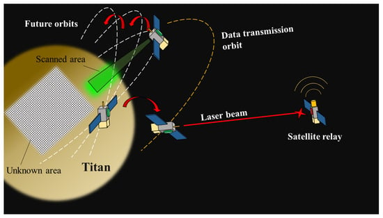
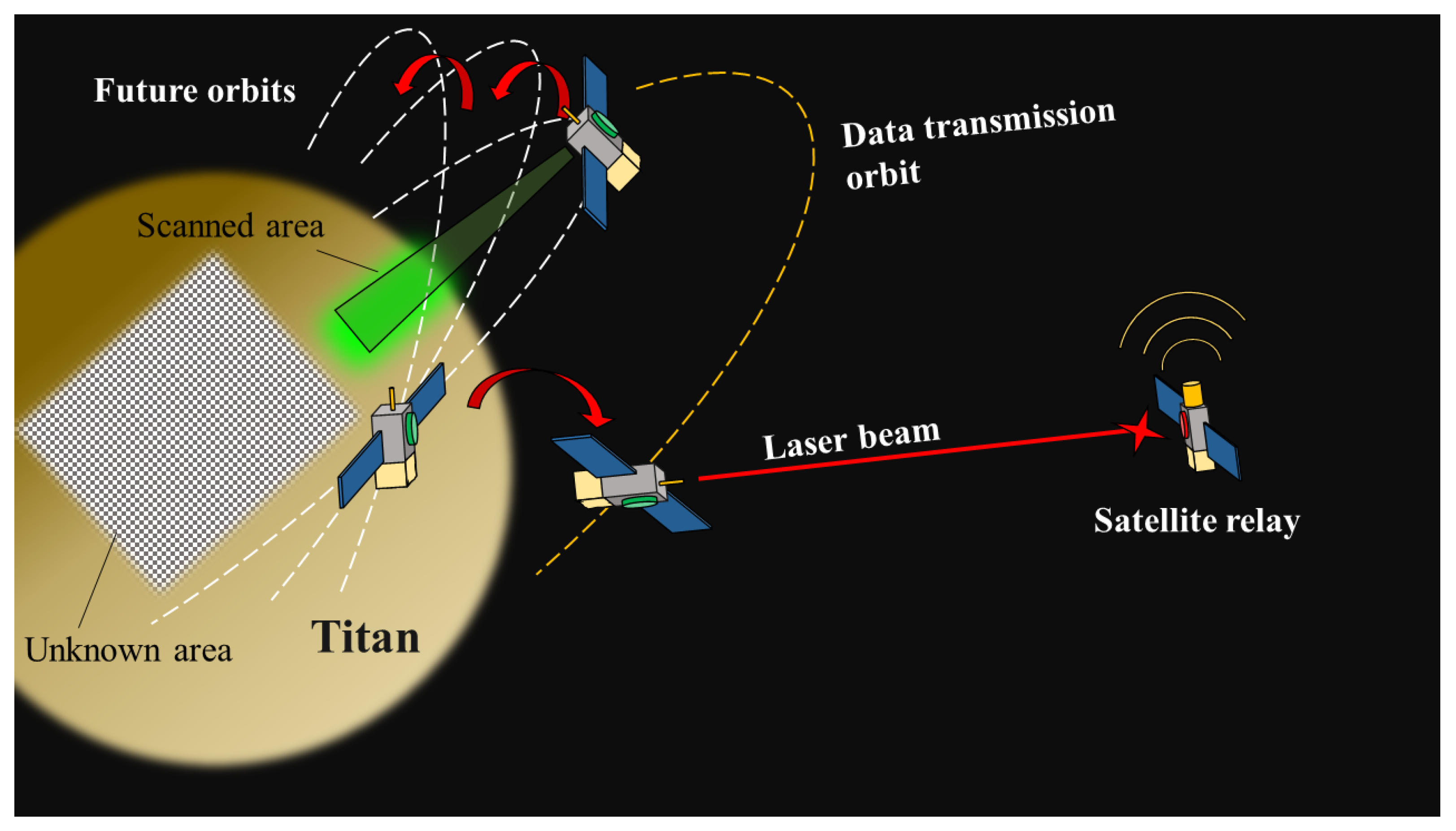
The current approach to the practical use of space is characterized by a trend of increasing demands on the dynamic mobility and operational lifetime of satellites, especially those used in proliferated space systems. This stems both from the growing number of target functions of a single space vehicle and from the involvement of private capital in the space industry [1,2,3], which necessitates the search for unique engineering solutions. The expansion of a spacecraft’s target functions implies a trend towards the creation of multi-role vehicles capable of performing various tasks that require different satellite orientations alongside orbit maneuvering [4,5,6] (see Figure 1). Examples include imaging deep space celestial objects, conducting laser communication sessions, and pointing highly directional antennas for testing data transmission rates and communication quality [7,8,9]. The interest of private companies is associated, for example, with the deployment of proliferated space systems to provide communication services on solar system natural space objects [10,11]. The process of deploying and operating such satellite constellations implies the need for spacecraft separation after a group of satellites is delivered to a reference orbit, its positioning associated with orbit phasing, orbit maintenance, and interorbital maneuvers. These operations involve the distribution of satellites which then keep their target positions in different orbital planes to create a uniform coverage zone. These operations are required because there are limited opportunities to launch batches of satellites in different rockets to remote natural space objects. Thus, these operations require propulsion systems (PSs) that are capable of generating thrust in multiple directions, in accordance with the orbital maneuver sequence schedule.
Figure 1.
Propulsion-intensive dynamic mission in orbit of natural space object. Red arrows represent trajectories of satellites presented. Dashed white and orange lines represent orbits of satellites presented.
Traditionally, small satellites employ unidirectional chemical or electric propulsion systems (EPSs), with thrust vector alteration being handled by the spacecraft’s attitude determination and control system (ADCS) [12,13]. This means that before activating the main propulsion system, the spacecraft must first re-orient itself. This approach requires additional propellant reserves and proves to be rather inefficient, as in such scenarios, the capabilities for spacecraft re-orientation are ultimately limited by the power allocated for the ADCS and its capabilities. While using several unidirectional thrusters with non-collinear axes to alter the EPS thrust vector without the use of the ADCS is a possibility, this method is critically flawed as it leads to excessive complexity and an increase in the mass and volume of the EPS.
The most promising solution appears to be the development of propulsion systems with thrust-vectoring control (TVC) realized within a single thruster. Implementing TVC in plasma thrusters is a known approach for EPSs based on ion and other types of plasma accelerators, for instance, through electrode segmentation [14,15,16] or other methods [17,18,19,20,21,22]. However, such solutions impose certain limitations on the EPS service life and their potential onboard applications. Furthermore, TVC can be implemented in an EPS mechanically by gimbaling a unidirectional thruster, analogous to liquid rocket engine nozzles. Yet, this method introduces additional risks associated with increased complexity and mass of the PS structure, making it unsuitable for use on small spacecraft.
To achieve TVC within a single device, the use of electrodeless plasma thrusters (EPTs) is an approach proven in-orbitally [20,23]. Their principle of operation is based on gas ionization using an alternating electromagnetic field generated by an inductor and on plasma acceleration caused by several mechanisms arising from the interaction between the electromagnetic and static magnetic fields. EPTs offer a number of advantages, such as the ability to vary thrust characteristics over a wide range [24] and a low number of components, which reduces production risks and costs [24]. TVC in EPTs can be implemented by employing several cylindrical discharge chambers, open at both ends, which enables thrust generation in six directions and allows for the formation of a spatially oriented resultant thrust vector [23,24]. Another possibility is the use of bidirectional electrodeless plasma thrusters (BDEPTs), whose operations have been successfully demonstrated in space [24], or EPTs with close ring-shaped gas discharge chambers capable of generating thrust in three mutually perpendicular directions [25,26]. These examples demonstrate the feasibility of achieving TVC by modifying the geometry and the number of discharge chambers. Furthermore, controlling the direction of the plasma flow in an EPT by altering the configuration of the applied external magnetic field is another method [21,27,28,29,30,31,32,33,34]. In 2017, Merino M. et al. presented simulation studies demonstrating the capability of the magnetic nozzle to control the direction of the charged particle flows [21,27]. Then, these works resulted in the proposition of the U-shaped thruster with magnetic thrust vector control [28]. Later, Takahashi K. et al. proposed several studies on the experimental investigation of the thruster with the magnetic nozzle capable to change the direction of the charged particle flows and experimentally demonstrate the mechanisms behind the processes governing the alterations. Up to 2025, despite the solid scientific background in the field of steering magnetic nozzles, fully integrated electrodeless plasma propulsion systems with magnetic thrust vector control implemented as complete space-operated units have been reported only in limited form. Moreover, these simulations and experiments have been focused on the study of the flows in the magnetic nozzles and have not focused on the initial processes occurring in such devices, including the gas discharge ignition. In 2024, the MTVEPT developed by the research group led by Shumeiko A. was launched into space and successfully demonstrated its propulsion capabilities onboard a satellite of the small form-factor [34]. However, the results on the experimental studies of the background processes that support the operations of such thrusters are still required to be reported in more detail.
The operation of any plasma sources, including those in the thrusters, begins with the gas breakdown of the propellant. In electrode-free plasma sources, discharges are initiated by alternating electric fields. The radiofrequency (RF) breakdown of low-pressure gas is quite well studied in the frequency range of 1–100 MHz [35,36,37,38,39,40,41]. Three main plasma source schemes are used for working with RF discharges: capacitively coupled plasma (CCP) sources, inductively coupled plasma (ICP) sources, and ICP sources with an external magnetic field. It is worth mentioning the contribution to the study of RF breakdown in low-pressure gases in the frequency range of 1–100 MHz by such scientists as: Kihara T. [35], Lisovsky V. [36], Boswell R. [37], Radmilovic-Radjenovic M. [38,39], Wiebold M. [40] and others. In particular, Radmilovic-Radjenovic M. [38,39], Wiebold M. [40] and Kumar S. [41] theoretically and experimentally studied the ignition processes of discharge in unidirectional EPT. Theoretical and experimental work on the study of discharge ignition in EPT capable of generating thrust vector in several directions has been carried out only for some schemes including BDEPT [42] and thrusters with a closed ring-shaped gas discharge chamber [25]. However, an investigation on the discharge ignition modes in the EPT with magnetic thrust vector direction control, that can be considered as one of the most promising schemes, has not yet been conducted. It is necessary to conduct experiments and develop theoretical foundations that describe the ignition of a discharge in such a device to advance its development for the proliferated practical applications. This paper presents an experimental study of the ignition thresholds of the discharge in the electrodeless plasma thruster with magnetic thrust-vectoring (MTVEPT) utilizing argon as the propellant. The scope of the present work is limited to discharge ignition phenomena and does not include quantitative thrust-vectoring performance characterization.
In Section 2, the MTVEPT scheme and the operational principles and parameters are discussed. Section 3 presents the description of the experimental setup. Section 4 provides an overview of the methodology used to conduct experiments and process the experimental data. Section 5 presents the results. In Section 6, the discussion on the experimental results provides the theoretical justification of the obtained trends of the determined threshold electric field dependencies from thruster parameters. Section 7 contains the conclusion.
2. Electrodeless Plasma Thruster with Magnetic Thrust-Vectoring
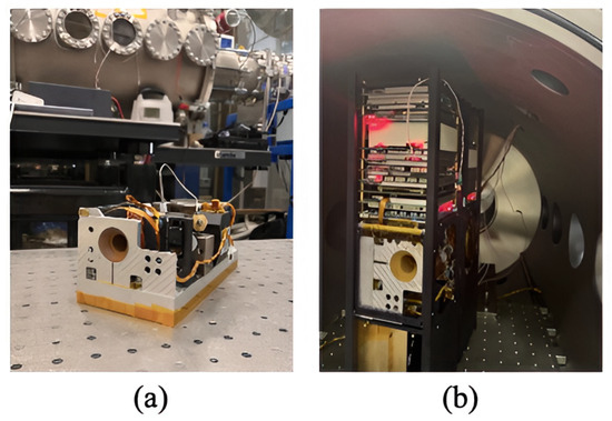
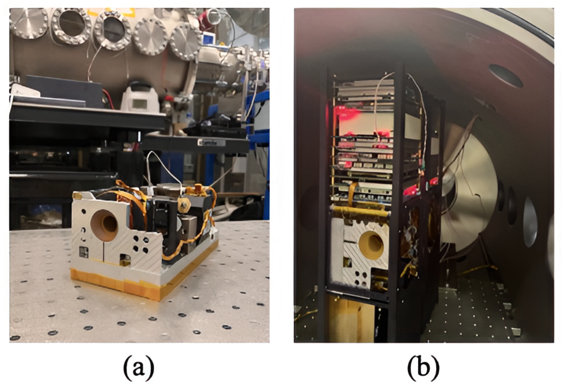
The MTVEPT investigated in this work is designed for small spacecraft of the CubeSat type [43,44]. However, due to its simple design and unified interface for connection to the onboard power supply system, it can also be integrated into spacecraft of other types. The main characteristics of the MTVEPT and the results from its in-orbit demonstration are discussed in detail in the work by Shumeiko et al. [34,37,38]. The overall dimensions of the device correspond to a 2U size, which measures 200 × 100 × 95 mm in three dimensions according to the common classification. The mass of the unit, including the fueled propellant storage and feeding system, is 2.78 kg. Within the achievable set of input parameters, the maximum thrust of the MTVEPT, as for the BDEPT, can be up to 10 mN, but the maximum specific impulse reaches 900 s, and the peak power consumption is up to 75 W [34]. Figure 2a shows the external view of the flight-ready propulsion system based on the electrodeless plasma thruster with magnetic thrust-vectoring. Figure 2b presents a photograph of the thruster integrated into a 6U CubeSat platform during functional testing of the spacecraft systems in a space environment simulation chamber.
Figure 2.
Electrodeless plasma thrusters with magnetic thrust-vectoring: (a) external view of MTVEPT; (b) MTVEPT integrated into satellite of small form-factor.
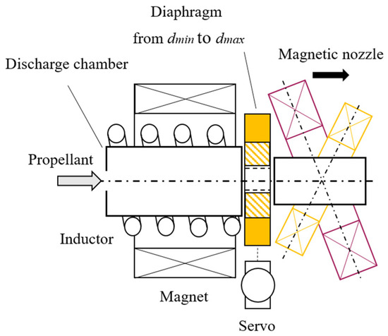
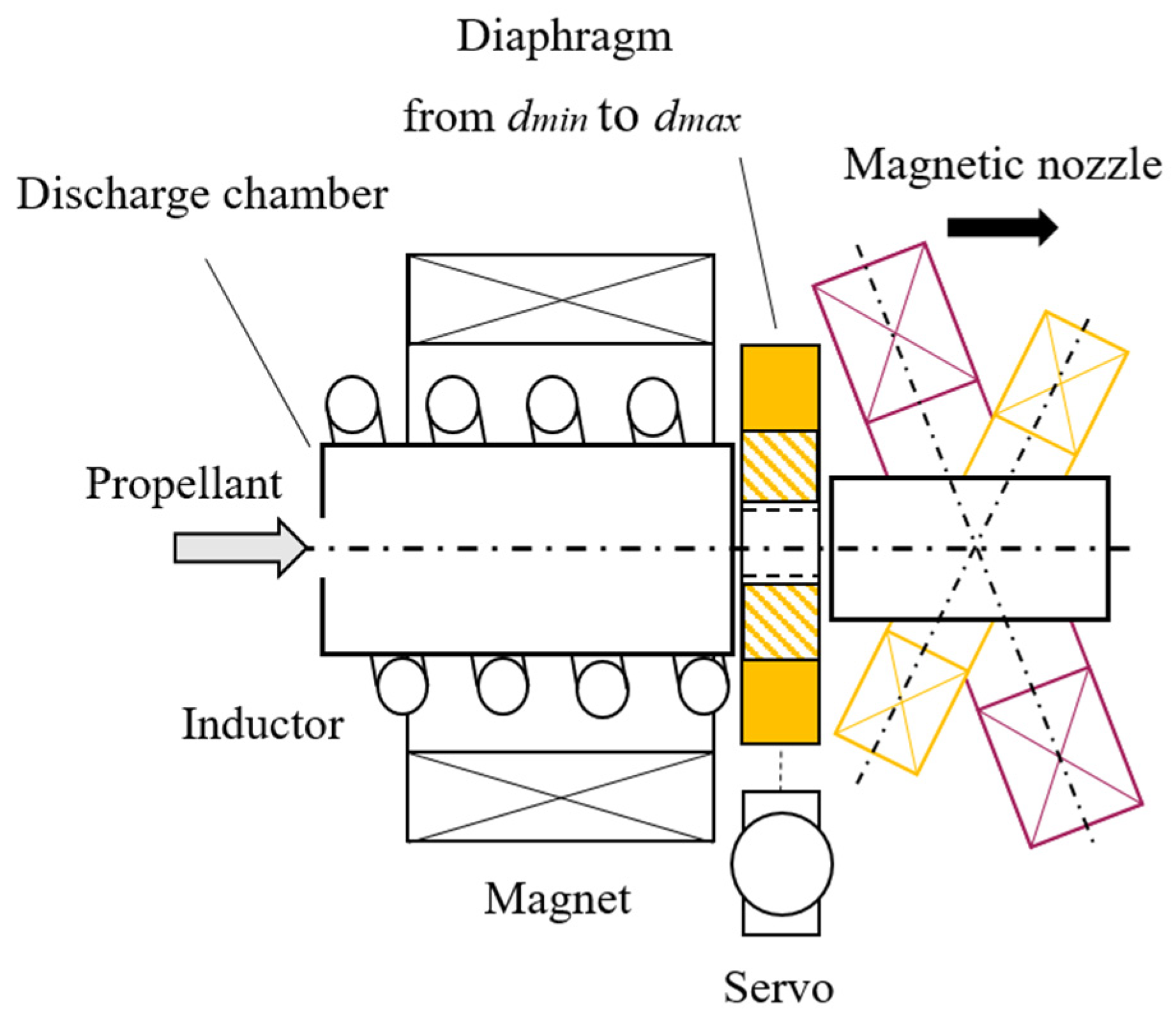
The design of the MTVEPT used in this study is largely similar to existing EPT solutions [18,20,24,26,27,28]. It contains a chamber and an inductor that creates an alternating electromagnetic field but incorporates a number of distinctive features. Unlike conventional unidirectional EPTs, the proposed MTVEPT combines: a magnetic nozzle capable of steering plasma flow direction and a variable diaphragm for discharge channel cross-section control and operation under both forward and reverse magnetic field configurations within a single propulsion architecture (highlighted in Figure 3).
Figure 3.
Scheme of MTVEPT. Black arrow represents normal (not-inclined) direction of thrust. Grey arrow represents point at which propellant is supplied to gas discharge chamber.
An inductor and an electromagnet are mounted around the gas discharge chamber, which is fabricated from a heat-resistant polymer using 3D printing. The electromagnet confines electron drift in the radial direction, thereby reducing the rate of charged particle dissipation and facilitating the ionization of the propellant. The diaphragm is positioned between the inductor and the magnetic nozzle and serves to vary the cross-sectional area of the discharge chamber. This design can increase the local pressure (and, consequently, the discharge ignition threshold) in the discharge region under fixed fuel flow conditions by reducing the outlet cross-sectional area, which qualitatively corresponds to the behavior of a Paschen-type discharge. The use of a diaphragm is particularly advantageous for plasma thrusters on small spacecraft, which typically have limited available power and modest propellant reserves.
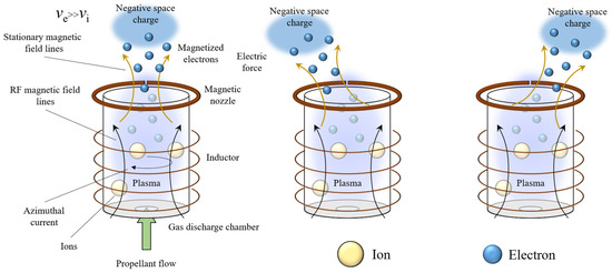
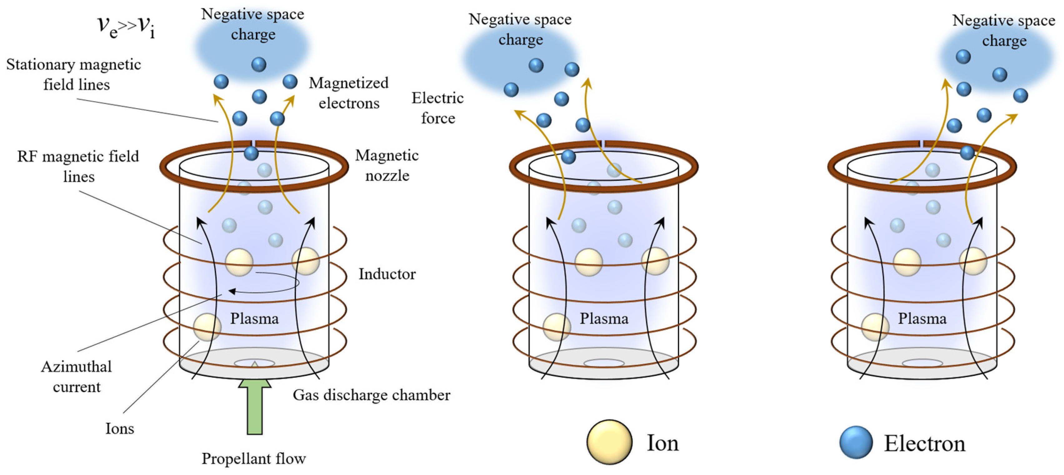
The operating principle of such devices is based on the inductive ionization of the propellant. An alternating electric current flows through the inductor coil, inducing an alternating magnetic field within the volume of the discharge chamber. According to Faraday’s law of electromagnetic induction, this field gives rise to azimuthal electric fields that accelerate free electrons. These electrons collide with neutral atoms of the propellant and thereby trigger an avalanche ionization process, increasing the ionization degree of the propellant.
This process leads to the formation of quasi-neutral plasma within the gas discharge channel (Figure 4). Due to their low mass, electrons exhibit higher velocities compared to ions and are more strongly influenced by the magnetic field of the magnetic nozzle. As a result, electrons become magnetized and move along the magnetic field lines of the static magnetic field, leaving the discharge channel faster than ions. This leads to the formation of an extended ion acceleration region due to the presence of an axial electric potential gradient along the thruster channel. The ions are accelerated in the resulting electric field and, upon exiting the thruster, generate thrust. Since the electrons are magnetized by the magnetic nozzle field, their displacement relative to the axis of the gas discharge chamber can be controlled. This makes it possible to alter the direction of the electric potential in space, thereby changing the direction of the electric force vector acting on the ions. Since the ions generate thrust, changing the direction of the force acting on them in this way allows us to alter the thrust vector of the electrodeless plasma thruster. We have implemented this principle in the design of a specially configured magnetic nozzle, the operating principle of which is discussed in detail below.
Figure 4.
Schematic diagram of the operating principle of an electrodeless plasma thruster. Black arrows represent induced eddy electric and axial magnetic fields. Orange arrows represent externally-applied stationary magnetic field lines. Green arrow represents point at which propellant is supplied to gas discharge chamber.
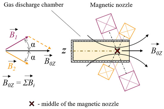
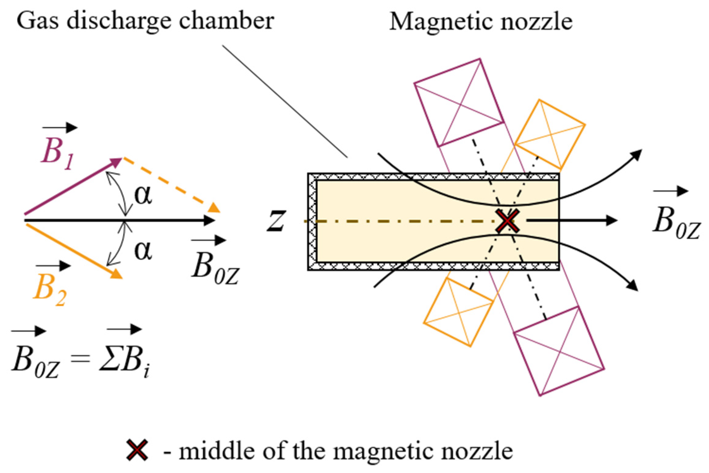
The key feature of the magnetic nozzle operation is the generation of a magnetic field strength sufficient to satisfy the electron magnetization condition of the plasma. Thus, by modifying the geometry of the external magnetic field, it is possible to control the direction of displacement of magnetized electrons at the exit of the acceleration channel. In turn, this leads to a modification of the direction of the electric potential gradient, which results in a change in the ion motion direction and, consequently, enables thrust-vectoring of the thruster. This principle forms the basis of the magnetic nozzle with a special configuration implemented in the MTVEPT design shown in Figure 3. The specially designed magnetic nozzle assembly consists of two electromagnets—a smaller one and a larger one—whose axes are oriented at identical angles to the axis of the discharge chamber (see Figure 5).
Figure 5.
Operating principle of magnetic nozzle of special configuration.
The geometric and electrical characteristics of the electromagnets are designed so that at specific coil current values, the magnitudes of the magnetic field generated by them can be identical. In this case, given the equality of the inclination angles of the electromagnet planes relative to the discharge chamber axis, the vector sum of the fields they produce results in the formation of an axial resultant field, coaxial with the axis of the MTVEPT discharge chamber at the point of intersection of the electromagnet axes. When only one of the electromagnets is operational, the resultant magnetic field is directed towards the discharge chamber axis at an angle equal to the inclination angle of that electromagnet’s plane. Thus, in the investigated device, magnetic vectoring of the plasma flow is achieved within a plane, covering a total divergence angle of 15° [21,27,28].
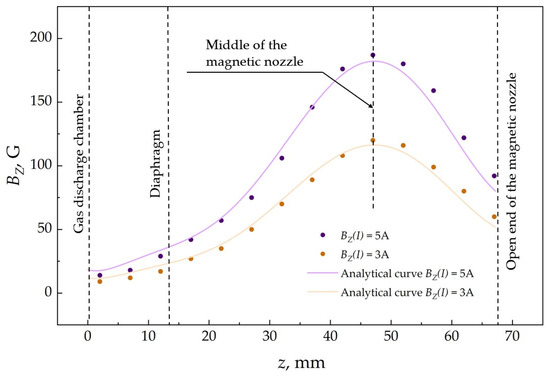
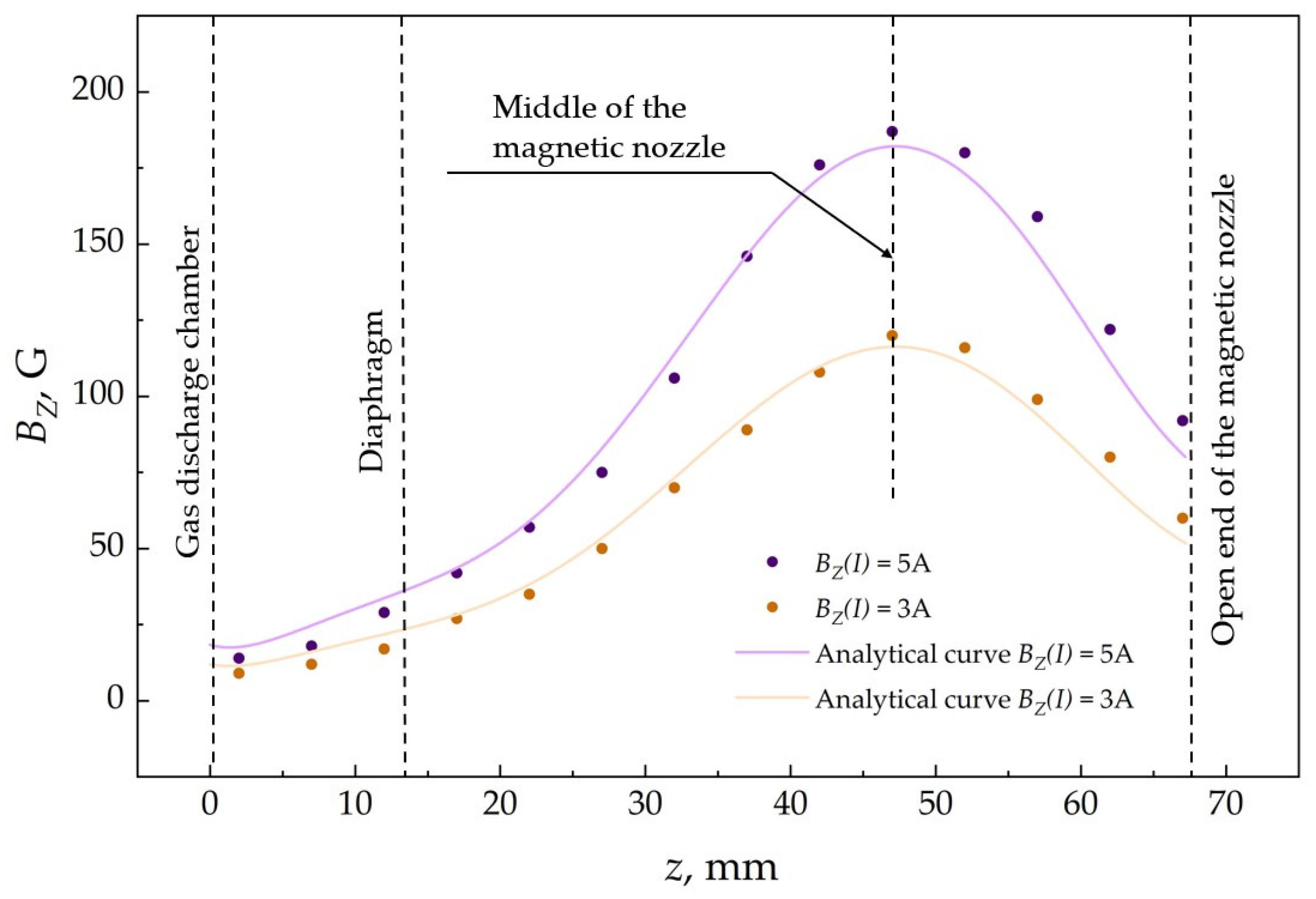
Important characteristics of the EPT are the distribution of the magnetic nozzle’s magnetic field along the length of the discharge channel and the peak value of the magnetic field magnitude on the channel axis. The peak magnetic field at the center of the magnetic nozzle determines the magnetization condition of the plasma’s electron component, which is described by the value of the Hall parameter, β, and, consequently, the thruster’s thrust generated by electromagnetic effects [38]. In this manuscript, the magnetic field affects the cyclotron frequency of an electron and has a numerical effect on the ignition of the discharge. This study examines the dependence of the magnetic field intensity on the magnetic nozzle electromagnets when the current changes within 0–5 A. Using an AlphaLab Inc. GM-2 gaussmeter with a cylindrical Hall probe, experimental data on the distribution of the magnetic field magnitude of the magnetic nozzle along the thruster channel length Bz(I) are obtained for the simultaneous operation of both electromagnets at two coil current values—3.0 A and 5.0 A. The results are presented in Figure 6. Furthermore, for the purpose of verifying the obtained data, Figure 6 also shows the results of numerical modeling for similar operational modes of the magnetic nozzle. It is evident that the experimental data are in close agreement with the simulation results with a high degree of accuracy, which confirms the consistency between the experimentally measured and numerically estimated magnetic field distributions [45]. The peak magnetic field magnitudes are 120 G and 187 G, respectively, which satisfies the conditions for magnetization of the plasma’s electron component given the known geometric parameters of the system [45]. The magnetic field strength distribution within the magnetic nozzle was simulated in COMSOL Multiphysics 6.1 to verify the consistency between engineering estimates and the actual achievable results. The numerically obtained data show good agreement with the experimental results, which confirms the validity of the applied simplified engineering approaches. This, in turn, supports their applicability at the preliminary design stage for estimating thrust characteristics and evaluating plasma parameters of the device.
Figure 6.
Distribution of externally applied static magnetic field within length of gas discharge chamber. Experimental uncertainty in determining of externally applied static magnetic field, Bz(I), is 2%, and uncertainty in measuring axial coordinate is 0.5 mm.
3. Experimental Setup
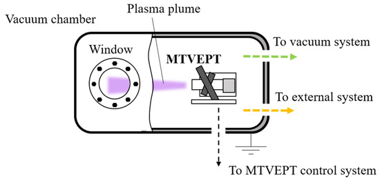
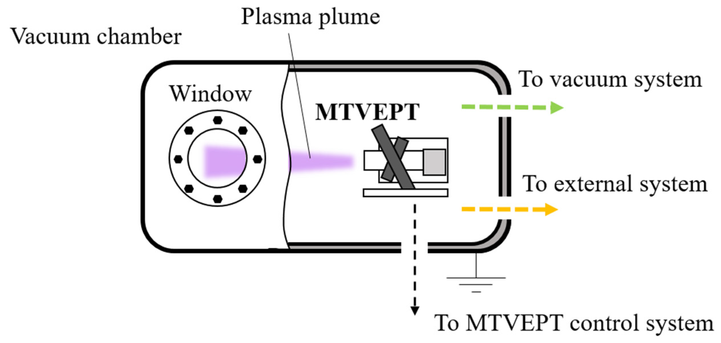
The equipment required for the experimental study to determine the threshold power electric field necessary for initiating a RF-discharge in the MTVEPT consists of four main groups: MTVEPT, the vacuum system, the control system and the external auxiliary system (see Figure 7). During the experiment, the MTVEPT is installed inside a vacuum chamber at a dynamic pressure of about 4.0 10−3 torr. The design and configuration of the MTVEPT are described in detail in Section 2. The MTVEPT control system is connected through multichannel hermetic flange feedthroughs mounted on the outer surface of the vacuum chamber. The control system itself represents specialized software, which is described in detail in [46]. It helps to control the power supplied to the inductor and the current flowing through the magnetic nozzle, thereby adjusting the thrust vector and its direction. The vacuum and auxiliary systems are briefly outlined below.
Figure 7.
Principle scheme of experimental setup.
3.1. External Systems
The external system consists of two subsystems: the propellant storage and supply system (PSSS) and the power supply board (PSB). The PSSS includes a propellant tank (argon), a pressure-reducing valve that lowers the gas pressure to the operating parameters of the flow controller, an electromagnetic propellant flow controller RRG-12 by Eltochpribor, Moscow, Russia, a controller unit BUIP-1M by Eltochpribor, Moscow, Russia and a piping network that delivers the propellant to the consumer. The PSSS is connected to the propellant supply system inside the vacuum chamber via Swagelok fittings located on the vacuum chamber surface. Inside the vacuum chamber, the propellant supply system consists of a silicone tube connected to the gas inlet channel of the plasma thruster, ensuring direct delivery of the propellant into the discharge chamber of the MTVEPT.
The PSB consists of several independent direct current power supplies that provide power to the MTVEPT control system, the generator, the servo drive and the magnetic plasma confinement system. The power supplies are connected through multichannel hermetic flange feedthroughs and a cable system.
3.2. Vacuum Systems
The vacuum system is designed to approximately simulate the conditions of outer space. It consists of a vacuum chamber, an environment monitoring system and a pumping system. The pumping system includes two lines: a medium-vacuum line and a high-vacuum line. Forevacuum is achieved using the oil-free scroll pump ISP-500C by Anesta Iwata, Yokohama, Japan, while high vacuum is maintained by the turbomolecular pump TMP-1003M by Shimadzu, Kyoto, Japan. Pressure inside the vacuum chamber is monitored with vacuum gauges CC-10 by The Fredericks Company, Huntingdon Valley, PA, USA and ACM-300 by ATOVAC, Yongin, Korea.
The ultimate base pressure in the vacuum chamber is 10−6 torr. The pumping speed of the turbomolecular pump for nitrogen is 1050 L/s, while the forevacuum pump provides a pumping speed of 500 L/min. Given these pump performance parameters, the minimum pressure achieved during operation is approximately 4.0 10−3 torr. In the pressure range from 10−9 to 10−3 torr, the vacuum gauges used provide an uncertainty not exceeding 0.2 decades, and in the range from 2.0 10−3 to 10−1 torr, the uncertainty does not exceed 15%. The uncertainty in the volumetric propellant flow rate measurement using the employed electromagnetic mass flow controller does not exceed 0.9%.
It should be noted that such relatively high-pressure levels in the vacuum chamber are reached only at the highest propellant flow rates—120 sccm and above—which do not correspond to the nominal operating regimes of the thruster intended for small spacecraft with limited propellant reserves. At typical operating conditions up to 20 sccm, the chamber pressure is lower than 8.0 10−4 torr and more representative of the space environment in low Earth orbit. Under these conditions, the influence of background pressure on discharge ignition is significantly reduced, which allows, with certain limitations, the applicability of the obtained results to practical applications to be assessed. It is important to note that the influence of pressure as a factor facilitating discharge ignition is not the defining difference between ground-based experiments and in-orbit operating conditions. In space conditions, an equally important factor is the presence of pronounced radiation, which increases the concentration of free charge carriers that initiate discharge; this effect can be considered functionally—equivalent to an effective increase in pressure during ground testing. The extension of the investigated range of propellant volumetric flow rates in this study is motivated by the scientific interest in examining the discharge ignition regions.
4. Methodology
4.1. Experimental Modes and Data Curation
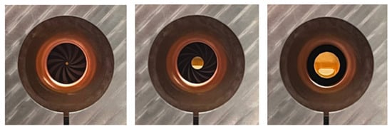
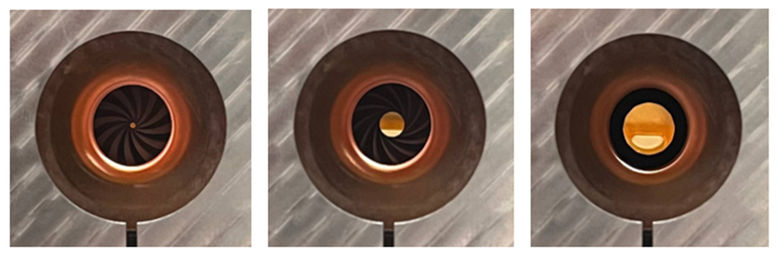
As mentioned in Section 2, the existing design and software of the MTVEPT make it possible to vary the discharge channel cross-sectional diameter. The adjustment is carried out by transmission of mechanical torque from the servo drive to the iris diaphragm, which ensures highly accurate regulation of its opening within a wide range from 1.0 to 14 mm (see Figure 8). In this study, the influence of the diaphragm aperture on the threshold electric field required for discharge ignition is evaluated. For the experiments, the extreme positions of the diaphragm are selected: fully closed (Figure 8, left) and fully open (Figure 8, right), with aperture diameters of 1.0 and 14 mm, respectively.
Figure 8.
Demonstration of minimum closed position of diaphragm (left), intermediate (center) and maximum opened position of diaphragm (right).
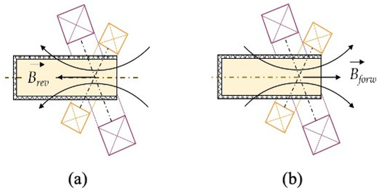
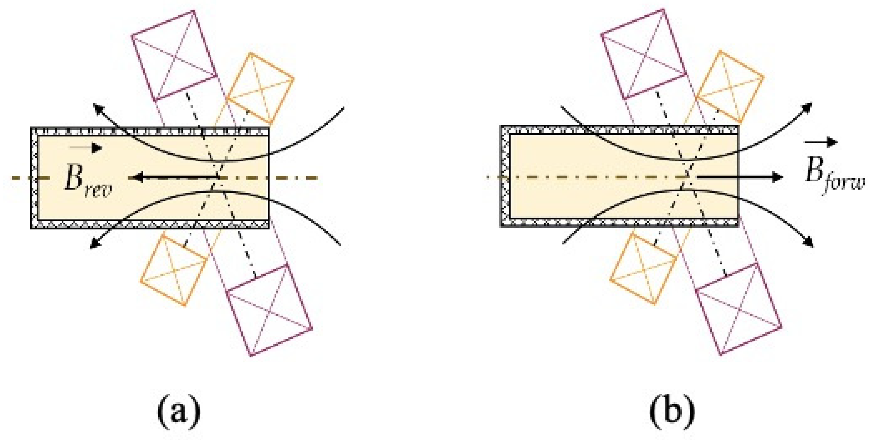
In addition, the existing software allows changing the polarity of the magnetic nozzle electromagnet terminals, that is reversing the current direction in the coils and, consequently, the orientation of the magnetic field lines. Thus, within the framework of this experimental study, the influence of two magnetic field orientations, direct and reverse, on the threshold electric field is also evaluated. The reverse orientation corresponds to the field lines directed inward into the discharge chamber, while the direct orientation corresponds to the field lines directed outward (see Figure 9). The magnetic field orientation modifies electron trajectories and electron confinement conditions inside the discharge chamber. This affects charged particle diffusion losses and ionization efficiency, thereby influencing the discharge ignition threshold.
Figure 9.
Schematic diagram of magnetic nozzle operation for (a) reverse and (b) forward magnetic field directions.
The position of the diaphragm affects the pressure inside the gas discharge chamber by changing the area of the outlet. The flow rate affects the concentration of the substance and the final pressure inside the chamber. The propagation of the magnetic field has a locking effect on the electrons, which changes their concentration inside the gas discharge chamber.
The purpose of this study is to determine the main ignition modes. And to determine the less energy-consuming one. During the experiment, the threshold electric field required for discharge ignition in the MTVEPT is investigated as a function of the volumetric flow rate of the propellant (argon), the orientation of the electromagnet field lines (direct and reverse), the current supplied to the electromagnets, and the diaphragm position (open and closed). The selected experimental modes were designed to study separately the effects of pressure variations caused by the diaphragm position, the magnetic field topology associated with forward and reverse field orientations, as well as the intensity of magnetic confinement, determined by the current in the electromagnets, on the discharge ignition process in the plasma accelerator under study. Such combinations allow for the independent investigation of the dominant physical mechanisms governing discharge ignition. A summary of the experimental series is presented in Table 1.
Table 1.
Parameters of recorded cases.
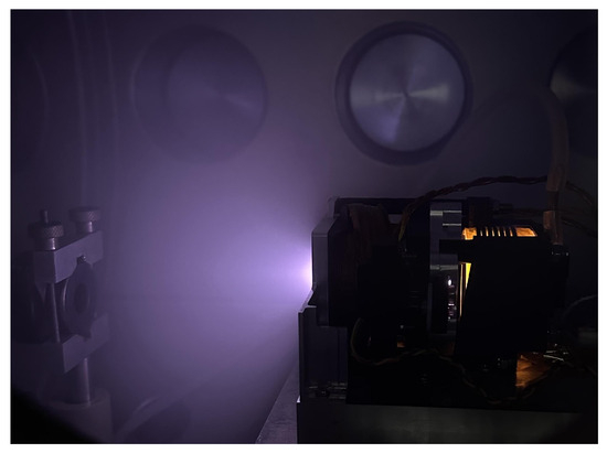
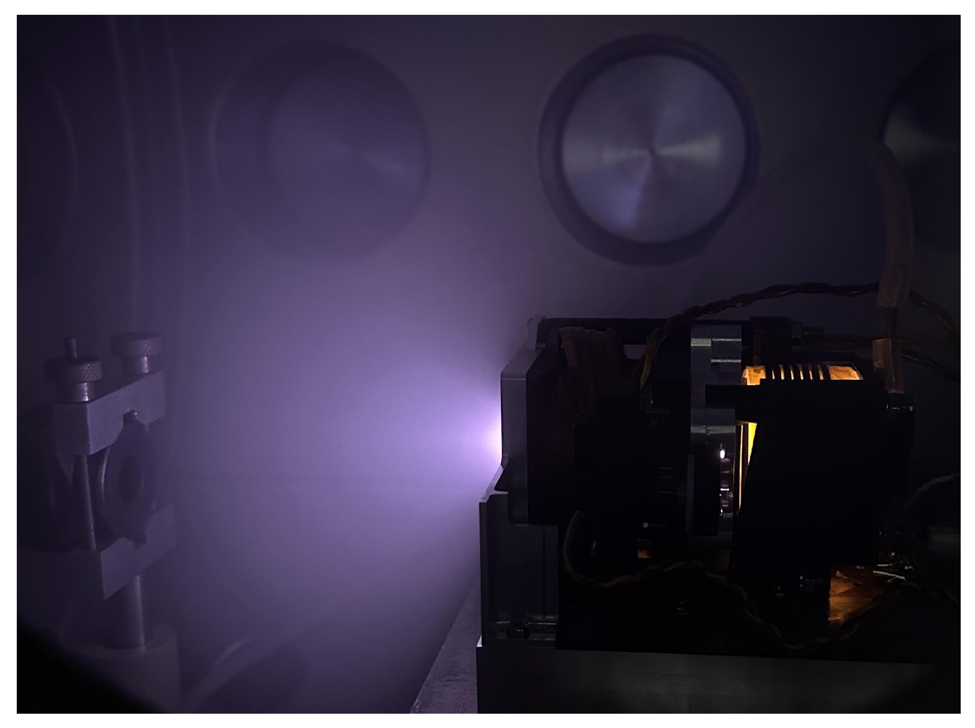
The determination of the threshold electric field necessary for RF discharge ignition in each experimental series was carried out by gradually increasing the power supplied to the inductor, expressed in the control software by “Power Mode”, until the discharge ignition occurred. The power mode can be recalculated to the values in the units of watt by multiplying the power mode by the coefficient 0.4. The ignition event is confirmed both visually, through the observation window of the vacuum chamber (see Figure 10), and analytically, by monitoring the changes in the electrical characteristics of the generator–inductor-load circuit caused by plasma formation and the corresponding increase in medium conductivity. The details of the power control supplied to the inductor are described in [46]. The power control system software allows setting the output power of the RF generator for the discharge ignition and the thrust generation modes, the magnetic field magnitude, the propellant flow rate, and the diaphragm position. The power control software allows checking the current in the inductor, the voltage on the inductor, the current and voltage related to the solenoids of the magnetic system, the temperature on the RF generator plate, and some other operational characteristics.
Figure 10.
MTVEPT in operation.
4.2. Threshold Electric Field Determination
The received electric field is converted to an alternative current amplitude flowing through the inductor by interpolation. According to Ampere’s law, such a current creates an alternating axial magnetic field Bz [42]:
where = 1.26 10−6 H/m is the vacuum permeability, is the number of inductor turns, is the axial length of the inductor, is the current amplitude, and denotes angular frequency of the radiofrequency current supplied to the antenna.
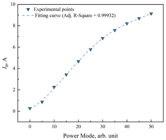
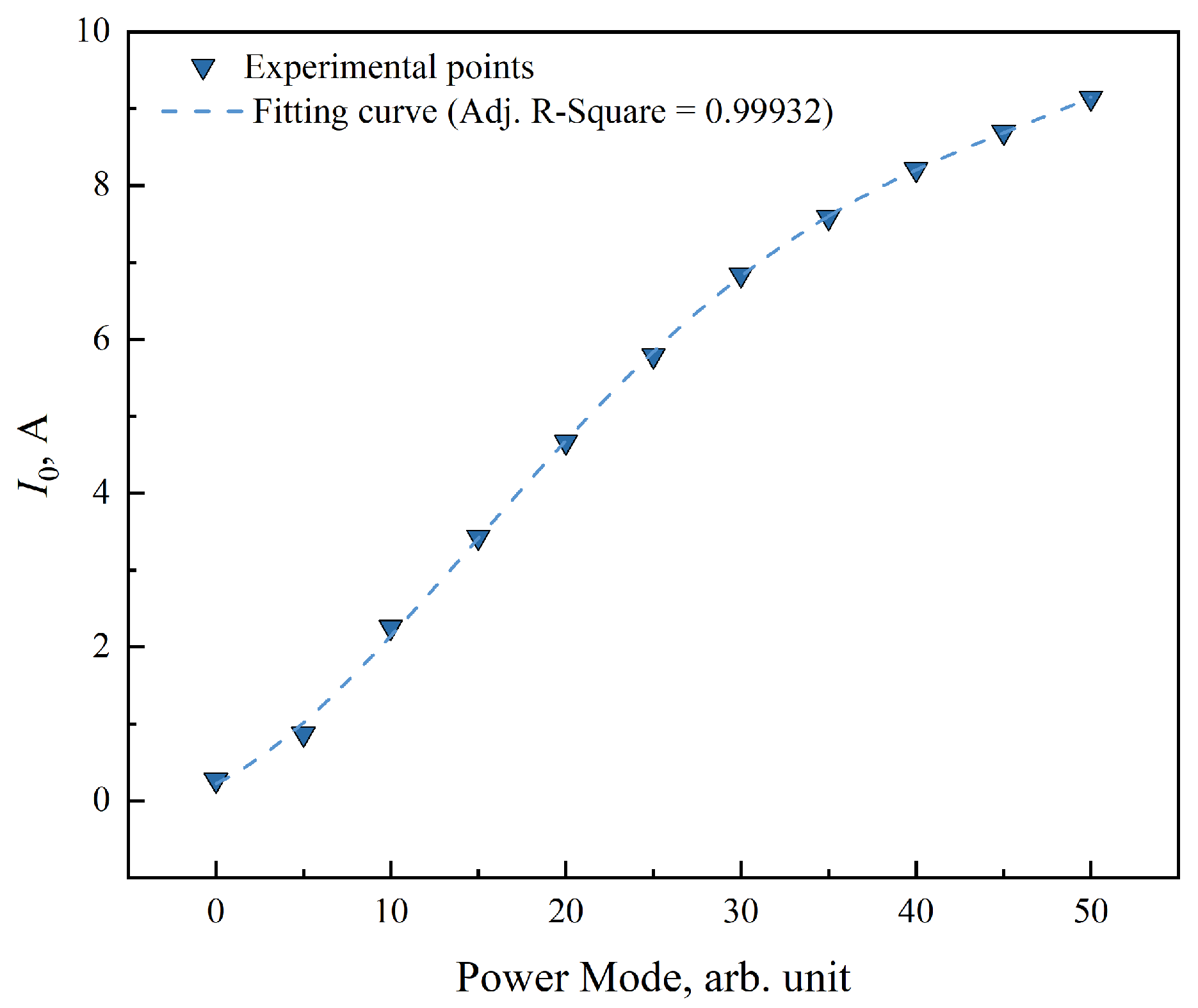
To calculate IRF0, the experimental dependence of the inductor current on the power supplied to the inductor in PM units is built (see Figure 11).
Figure 11.
Dependence of current in inductor on PM of RF generator. Power mode-to-watt by multiplying PM by coefficient 0.4. Estimated uncertainty for I0 is 5%.
The inductance equation for the solenoidal inductor used to calculate the equivalent number of turns [42]:
where is antenna inductance, is the cross-sectional area of the inductor.
Some parameters can be defined. The measured inductance is 17 μH, and antenna axial length is 40 mm. The distance between the antenna and the axis of the gas discharge chamber is 21 mm. The axial magnetic field produces an eddy azimuthal electric field E, according to the Faraday’s low and Maxwell’s equations [42]:
where r is the distance between axis of chamber and inductor.
The final equation to find out an eddy electric field is applied [42]:
5. Results
Based on the experimental data obtained for the selected series, graphical dependencies of the threshold electric field, E, are constructed in the coordinates of the magnetic field in current units B(I) and the propellant flow rate ṁ, in accordance with Expressions (1)–(4). Two cases of magnetic field orientation are considered: direct and reverse.
5.1. Reverse Direction Results
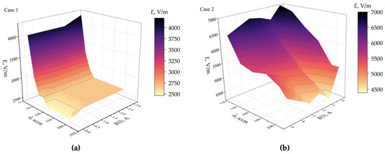
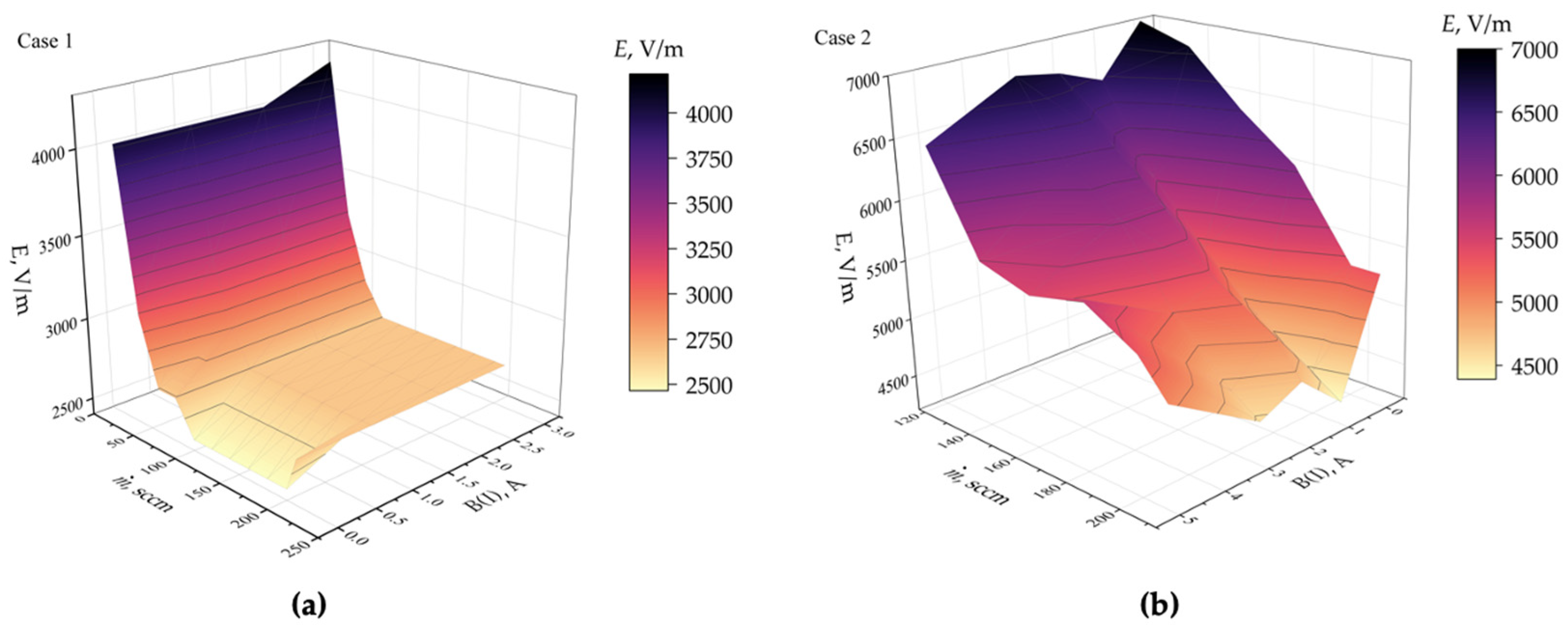
The obtained threshold electric field diagrams for the reverse magnetic field direction, as a function of B(I) and the propellant flow rate, for both open and closed diaphragm positions are shown in Figure 12.
Figure 12.
Case 1, closed diaphragm (a); Case 2, opened diaphragm (b). Measurement uncertainty for propellant flow rate, ṁ, is 2%, for magnetic field, B(I), is 2%, and uncertainty of calculated value, E, is 5%.
The ignition field strength ranges from 2.5 103 V/m to 7.0 103 V/m, depending on the propellant flow rate (20–210 sccm), the magnetic field strength (expressed in terms of solenoid current, 0–5.0 A), and the diaphragm aperture (1.0–14 mm). With the diaphragm closed, the average ignition field strength is approximately half that observed with the diaphragm open.
For the closed diaphragm configuration, as the propellant flow rate increases to 100 sccm, the threshold electric field strength exhibits a sharp decrease, settling at a steady value of approximately 2.6 103 V/m. As seen in Figure 12a, this steady-state ignition voltage is characteristic of almost the entire range of solenoid currents, except for experiments conducted in the absence of a magnetic field, which show a minimum threshold of about 2.5 103 V/m. This suggests that the magnetic field has an insignificant influence on the discharge ignition process when the diaphragm is closed.
In contrast, with the diaphragm open, a more gradual decrease in the threshold electric field is observed, from 7.0 103 V/m to 4.5 103 V/m at flow rates of 20 and 210 sccm, respectively. Under these conditions, the influence of the magnetic field on the ignition threshold becomes more pronounced. The graph clearly shows two local minima in the ignition field strength as the solenoid current increases. The entire ignition regime map can be divided into four alternating regions: two regions of decreasing and two regions of increasing ignition field strength with increasing solenoid current.
Region I is characterized by a decrease in the ignition field strength and is observed for B(I) values ranging from 0 to 1.0 A. region II marks the first increase in the field strength, occurring in the magnetic field range (expressed in current units) from 1.0 to 2.0 A. However, by the end of this increasing interval, the field strength does not reach its initial value observed at B(I) = 0 A. This is followed by region III, which shows a decrease in the ignition field strength for B(I) values from 2.0 to 3.0 A. Region IV is similar to Region II but exhibits a steeper rate of increase.
5.2. Forward Direction Results
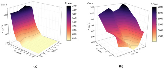
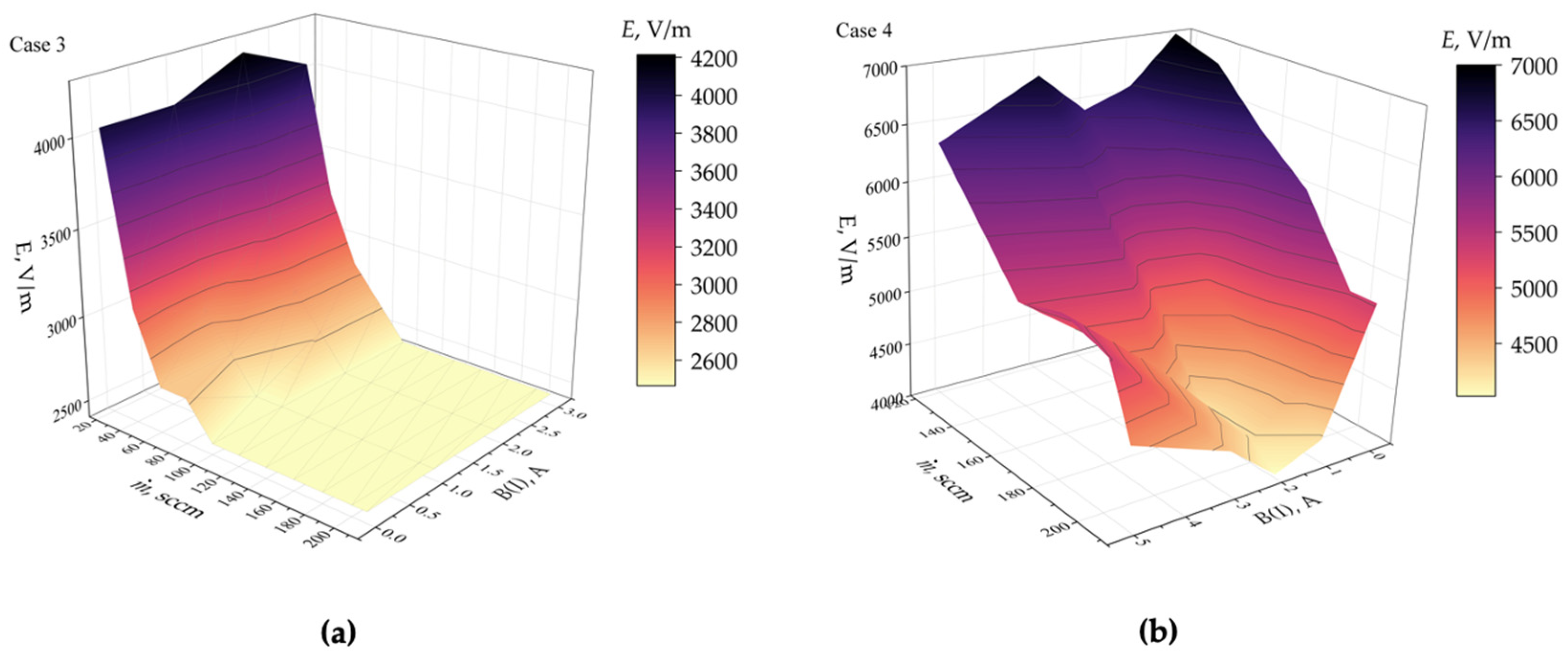
For the direct magnetic field orientation, the overall trends remain similar (see Figure 13).
Figure 13.
Case 3, closed diaphragm (a); Case 4, opened diaphragm (b). Measurement uncertainty for propellant flow rate ṁ, is 2%, for magnetic field, B(I), is 2%, and uncertainty of calculated value, E, is 5%.
With the diaphragm closed, the behavior of the ignition field with respect to the propellant flow rate is identical to that observed with the reverse field orientation, with the steady-state minimum reduced to 2.5 103 V/m. However, unlike in the reverse case, no further decrease in the minimum ignition field is observed in the absence of a magnetic field.
For the open diaphragm, only the first three regions of threshold electric field variation are evident at fixed flow rates, resulting in a single pronounced minimum located near B(I) = 2.0 A.
6. Discussions
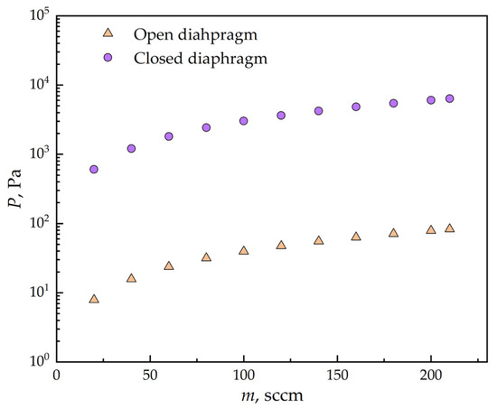
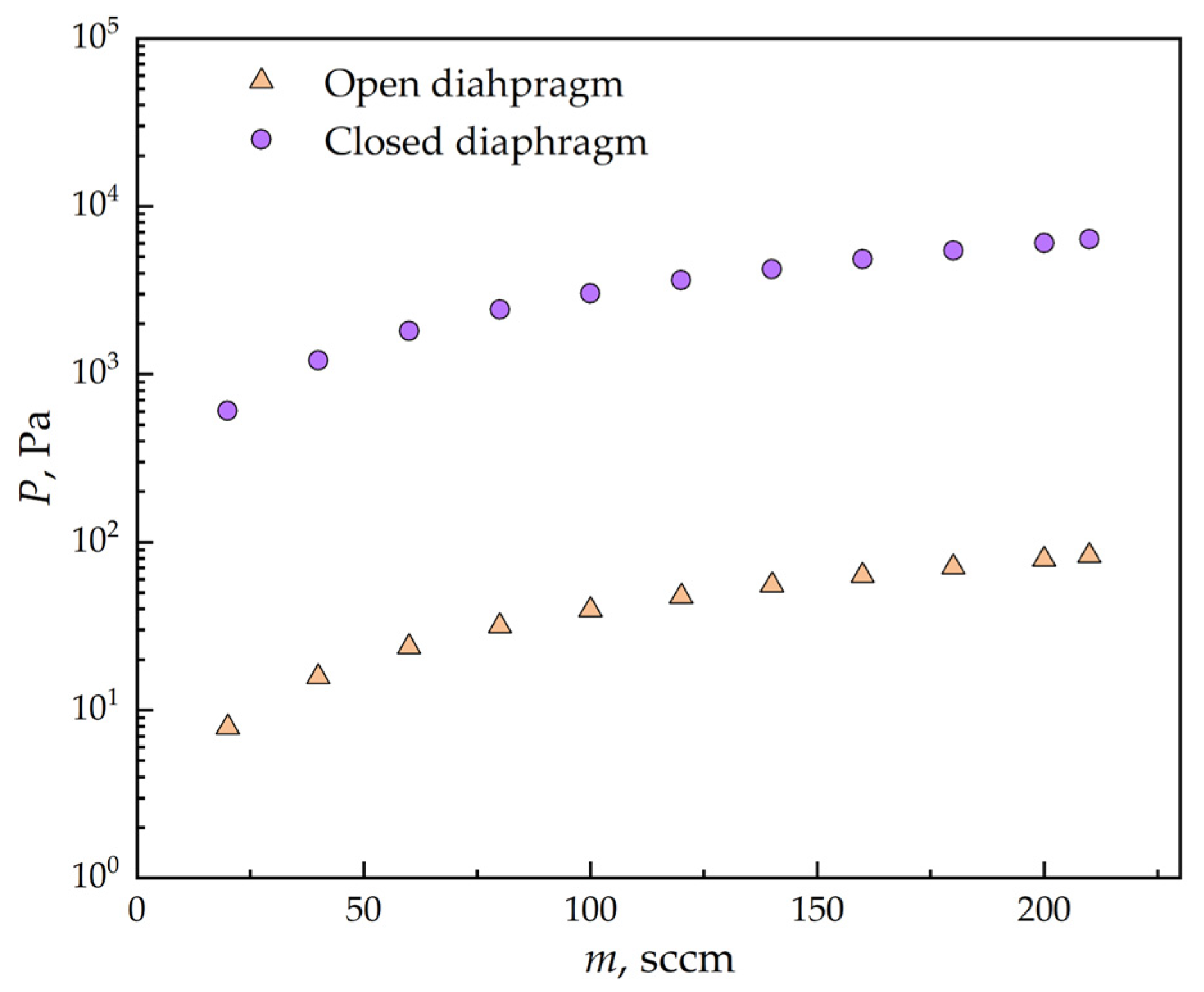
Let us examine the obtained results in more detail. For both magnetic field orientations, a decrease in the threshold electric field is observed with the increasing propellant flow rate. This effect is attributed to the rise in pressure inside the discharge chamber, which leads to a higher concentration of free charge carriers and, consequently, to an increased number of ionization processes per unit time. As a result, the ignition of the discharge is facilitated. To support this observation, Figure 14 presents the result of numerical simulations of the pressure distribution at the geometric center of the inductor for both open and closed diaphragm positions utilizing argon. Numerical simulations were performed in COMSOL Multiphysics 6.1 using the Free Molecular Flow interface for steady-state argon flow. The calculations were used to evaluate the pressure distribution inside the gas discharge chamber for various propellant flow rates. As part of the computational model, the 3D geometry of the gas discharge channel of the electrodeless plasma thruster and the working cavity of the vacuum chamber was recreated, including the arrangement of the gas pumping and pressure control systems. Using the known pumping speed of the turbomolecular pump and boundary conditions corresponding to the experimental procedure (temperature and an approximate value of the pressure on the walls of the vacuum chamber as part of a first-order approximation of the steady-state solution), the corresponding numerical results were obtained. The computational model was validated by comparing the numerical pressure values at points in the chamber corresponding to the locations of the vacuum gauges with the readings of the vacuum gauges during the experiment.
Figure 14.
Results of numerical simulation of pressure dependance on propellant flow rate inside gas discharge chamber in geometric center of inductor.
Closing the diaphragm, regardless of the magnetic field orientation, results in a sharper decrease in the threshold electric field, down to a steady minimum value of about 2.5 103 V/m at 100 sccm. This effect is caused by a significant increase in the pressure inside the discharge chamber, as compared to the experiments with the open diaphragm, due to the reduction in the exhaust cross-section. As a consequence, the number of ionization processes increases, followed by a reduction in the threshold electric field in accordance with Pashen’s law.
6.1. Reverse Direction
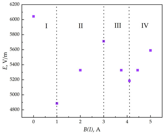
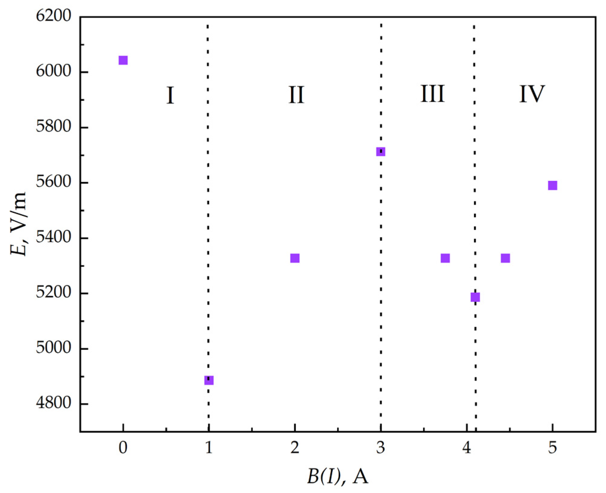
The most significant interest in the present work lies in the identified regions of the threshold electric field, corresponding to different values of the current in the electromagnets. Let us now examine in more detail some of the most representative ignition threshold regimes for the open-diaphragm configuration under different magnetic field configurations. As already noted, in the case of the open diaphragm with the reverse magnetic field orientation, sequentially alternating regions can be distinguished. Figure 15 shows the most illustrative experimental data for the series at a propellant flow rate of 180 sccm.
Figure 15.
Case 2: dependence of discharge ignition threshold electric field on B(I) with open diaphragm for propellant flow rate of 180 sccm under reverse magnetic field direction. Experimental uncertainties are 2% for magnetic field, B(I), and 5% for calculated threshold electric field, E.
The graph reveals four distinct regions: two characterized by a decrease (I and III) and two by an increase (II and IV) in ignition electric field as a function of the magnetic field in current units B(I). The ignition regions are identified according to the sign of the derivative dE/dB(I), corresponding to alternating intervals of increasing and decreasing ignition threshold electric field with increasing magnetic field strength. To explain in more detail the observed influence of magnetic field, it is necessary to consider the electron balance equation for a unidirectional electrodeless plasma thruster [42]:
where νi is the ionization collision frequency, ne is the electron density, B is the magnetic field induction, DTB is the transverse electron diffusion coefficient across the magnetic field lines, r denotes radial coordinates, DLB is the longitudinal electron diffusion coefficient along the magnetic field line, z is the axial coordinate, e is the electron charge, E is the electric field strength, ω is the angular frequency of the electric field, me is the electron mass, νen is the elastic electron–neutral collision frequency, and φ is the azimuthal coordinate.
The first term on the right side of Equation (5) represents electron generation, the second and the third terms describe electron losses due to longitudinal and transverse diffusion in the presence of the magnetic field and the fourth term accounts for electron drift under the influence of the external electric field. As is well known, the effect of the magnetic field on particle interactions within the plasma volume, particularly ionization processes, is determined by the ratio of the electron cyclotron frequency ωce to the collision frequency νe. The ratio is called Hall parameter β. In weakly ionized plasma, where the electron density is much lower than the neutral concentration (ne << nn), which is typical for small electrodeless plasma thrusters, the dominant form of interaction between electrons and other particles can be approximated as elastic scattering on neutral atoms. Within this approximation, the Hall parameter can be evaluated using νe ≈ νen.
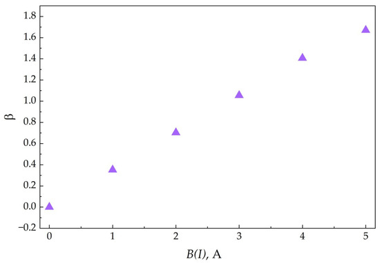
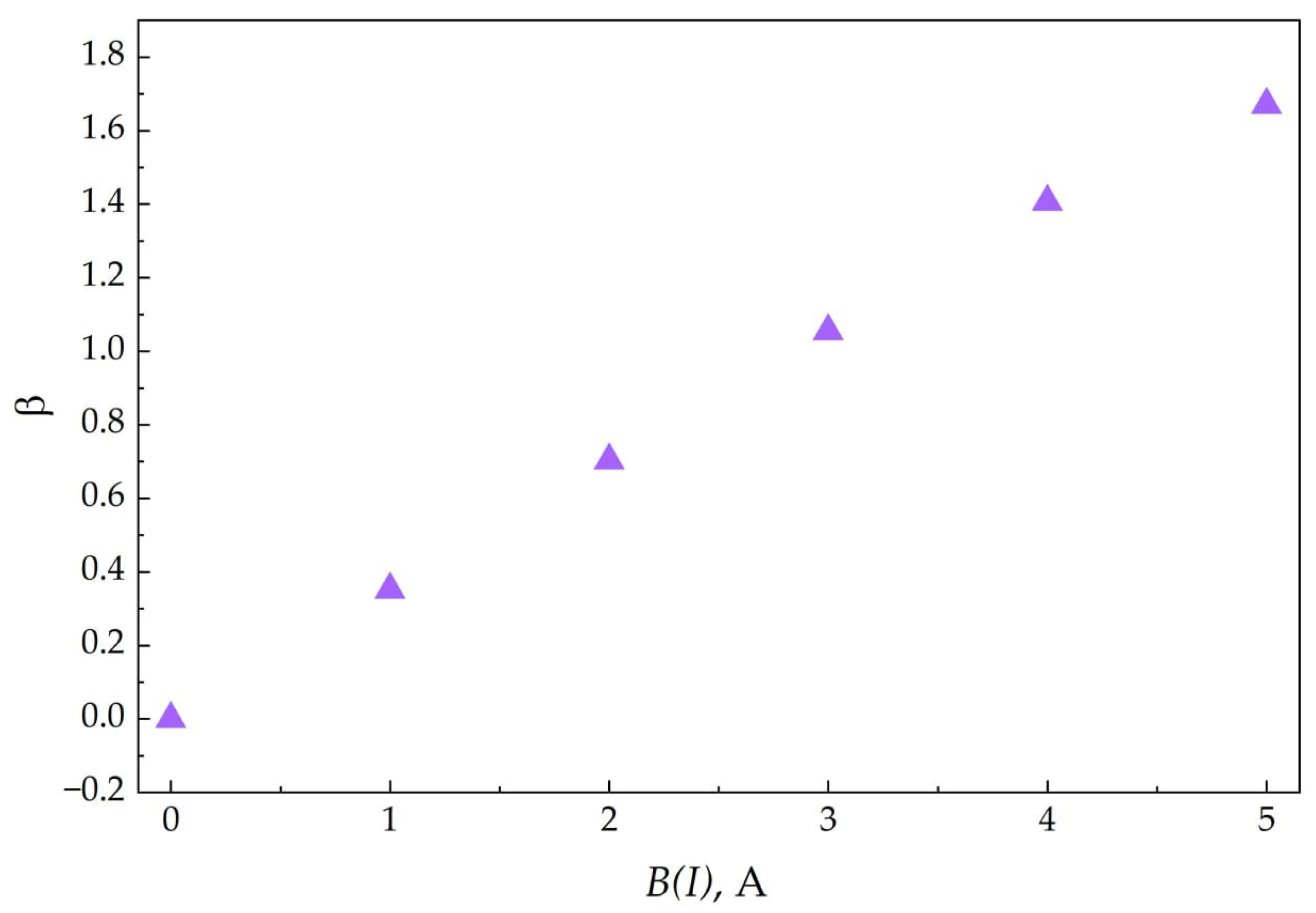
Based on the LXCat database, for the characteristic electron temperature of the plasma in this thruster Te ≈ 5.0 eV, the elastic scattering cross-section of electrons on argon atoms is determined to be σen ≈ 2.0 · 10−11 m2. Thus, using the available data on the pressure inside the discharge chamber at ṁ = 180 sccm (see Figure 15), along with the results of numerical modeling of the magnetic field as a function of the current in the electromagnets, an evaluation of the Hall parameter β is carried out over the entering range of B(I) for the integral plasma temperature of T = 300 K (see Figure 16).
Figure 16.
Dependence of the Hall parameter, , on the magnetic field induction expressed in current units B(I).
From Figure 16 it can be seen that the Hall parameter increases, as expected, with the growth of the magnetic field within the plasma volume. This affects the transverse electron diffusion coefficient, which is determined according to the following expression [42]:
where kB is the Boltzmann constant and ν is the particle collision frequency.
From Expression (6) it follows that as magnetic induction and hence the Hall parameter increases (under otherwise equal conductions), the transverse diffusion coefficient DTB decreases. In addition, the longitudinal diffusion coefficient in the presence of a magnetic field DLB is inversely proportional to the square of the magnetic induction and has the form DLB~1/B2. Thus, with an increasing magnetic field, a reduction in electron flux in both radial and axial directions should be observed, that is a decrease in the total number of charge particle losses on the chamber walls. Under these conditions, the ionization progresses and is consistent with the observed reduction in the ignition field in region I.
Based on the above considerations, the decrease in the threshold electric field with increasing magnetic field strength should continue until the Hall parameter becomes so large that the probability of particle collisions approaches zero [47]. Beyond this point, an unlimited growth of the ignition field is expected. Thus, the dependence of the threshold field on B should resemble a parabola. However, as can be seen from Figure 15, the behavior of the ignition electric field changes after reaching the first local minimum at the boundary of region I, at a certain value of the external magnetic field, thereby forming region II. In this region an increase in the threshold electric field is observed within the range of B(I) from 1.0 to 3.0 A. The increase can be explained by the fact that the ions generated in region I do not interact with the magnetic field and are deposited on the walls of the discharge chamber, imparting a positive charge to them. The electrons, localized near the chamber axis, form a volume negative charge. Under the influence of electrostatic forces, electrons, despite the reduced diffusion coefficients, begin to drift toward the chamber walls, thereby decreasing the concentration of free charge carriers near the chamber axis (ne)r≈0. This, in turn, leads to an increase in the threshold electric field.
Therefore, this phenomenon implies the need for a modification of the right side of Expression (5) by introducing a correction term that governs the variation in the transverse diffusion coefficient DTB. This term should be defined within a certain range of the Hall parameter β in order to account for electron losses in the radial direction, caused by the volumetric positive ion charge near the inner surface of the discharge chamber, despite the limitation of radial diffusion imposed by the magnetic field:
where (ne)r≈0 denotes the concentration of free electrons near axis of the discharge chamber, and a((ne)−1r≈0) denotes the coefficient characterizing the influence of the electric field, which arises due to charge separation, on the radial distribution of the electron concentration.
The value of the coefficient a((ne)−1r≈0) varies in the range from 1 to a certain value a0 >> 1. Its dependence on the Hall parameter can be expressed as follows: at β → 0 ⇒ a((ne)−1r≈0) = 1, at β >> 1 ⇒ a((ne)−1r≈0) = 1 and at β ≈ 1 ⇒ a((ne)−1r≈0) = a0. Let us attempt to clarify its physical meaning based on the obtained experimental data.
As mentioned earlier, the increase in the threshold electric field in region II is explained by the enhanced electron losses caused by the formation of a volumetric uncompensated positive ion charge near the discharge chamber wall. This effect is reflected in the behavior of the coefficient a((ne)−1r≈0), which, in the left limit β → 1−, typical for region II, sharply increases up to the value a0. This leads to an “artificial” increase in the transverse diffusion coefficient DTB and, consequently, to a rise in the ignition field. By “artificial” increase in DTB we mean the fact that, with the increasing B(I), the actual value of the transverse diffusion coefficient DTB continuously decreases, while the expression a((ne)−1r≈0)DTB increases.
The growth of radial electron losses under the influence of the ion electric field and the corresponding rise in the threshold field continues until the flux of electrons moving toward the discharge chamber walls compensates the excess charge and becomes equal to the flux of ions freely moving toward the chamber boundaries. At this point of equilibrium, the coefficient a((ne)−1r≈0) reaches its maximum value a0 at the right boundary of region II.
After reaching the described equilibrium, further increases in the current of the electromagnets lead to the formation of region II, characterized by a decrease in the threshold electric field. This can be explained by the fact that as B(I) increases, the electron cyclotron radius decreases and under conditions of reduced electron concentration due to the presence of uncompensated positive ion charge, the Hall parameter rises. As a result, the average energy of free electrons increases, facilitating the ionization process and thus lowering the threshold electric field for discharge ignition. In this regime, the coefficient a((ne)−1r≈0) in the right limit β → 1+, characteristics of region III, sharply decreases from a0 to 1 at the right boundary of region III, causing the product a((ne)−1r≈0)DTB to diminish, which is reflected in the reduction in the ignition electric field.
Further increases in the magnetic field strength—region IV—cause the cyclotron radius to shrink so much that electron trajectories become localized near the central axis, reducing the probability of impact ionization. With continued growth of the magnetic field, particle trajectories approach a geometry point, resulting in an unbounded increase in the threshold field. Consequently, the right side of Equation (7) must account for the increase in the ignition field caused by the absence of collisional processes. For this purpose, an additional coefficient b, associated with the increasing magnetic field, should be introduced into the equation.
where b is the coefficient accounting for the influence of the magnetic field on the frequency of electron interactions with neutral atoms. Thus, as B → ∞, νen → 0, which leads to .
Such behavior has already been reported in [47] in studies of charge particle dynamics in helium and xenon. It is shown that at Hall parameter values , the fraction of energy spent on ionization tends to zero.
6.2. Forward Direction
In this series of measurements with the diaphragm closed, the minimum steady-state ignition electric field strength is found to be lower than in the case of the reverse magnetic field orientation under otherwise similar conditions. Since charged particles move along the magnetic field lines, in the reverse configuration a fraction of electrons becomes “trapped” within the plasma volume. As a result, the particle concentration increases compared to experiments with the direct field orientation. This, in turn, reduces the electron mean free path and their average energy, making the discharge ignition more difficult.
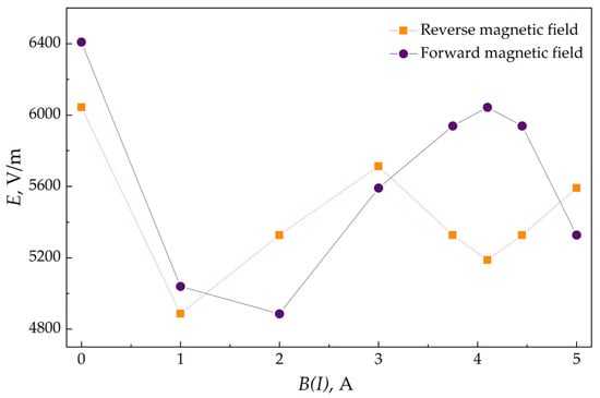
For a more explicit comparison Figure 15 and Figure 17 present the experimental ignition electric field dependencies as a function of B(I) for gas flow rates of 160 and 180 sccm with an open diaphragm, for direct and reverse magnetic field orientations, respectively.
Figure 17.
Dependence of discharge ignition threshold electric field on B(I) with open diaphragm, for flow rates of 160 and 180 sccm under forward and reverse magnetic field directions, respectively. Experimental uncertainties are 2% for magnetic field, B(I), and 5% for threshold electric field parameter, E. Data points are connected for clarity.
From Figure 17 it is clearly seen that the above-described dependences, characteristic of the reverse magnetic field orientation, develop at higher values of B(I) than in the direct orientation. As a result, within the selected range of B(I) from 0 to 5.0 A, only the first three of the four regions of ignition threshold behavior can be observed in the experiments with the direct magnetic field: a decreasing region of E (from 0 to 2.0 A), a growth region (from 2.0 to 4.0) and a subsequent decrease (from 4.0 to 5.0). This “stretching” along the abscissa indicates an inequality in the rates of the above-described processes occurring in the plasma volume under direct and reverse magnetic field orientations. The reduced rates in the case of the direct orientation can be attributed to a lower frequency of exchange processes between particles, arising due to relative differences in the concentration of charged species. These differences in charge carrier concentrations result not only from the lower propellant flow rate of the argon in the direct orientation, but also from the “trapping” effect, adhering electrons moving along the magnetic field lines to remain confined within the discharge chamber, thereby reducing longitudinal losses in the reverse configuration.
7. Conclusions
This paper presents the experimental study of the radiofrequency discharge ignition thresholds in the electrodeless plasma thruster with magnetic thrust-vectoring utilizing argon. The scope of this work is limited to discharge ignition phenomena and does not include a quantitative assessment of the characteristics of vector thrust control. The investigation focuses on the effects of the propellant flow rate (20–210 sccm), the magnetic field magnitude (expressed as solenoid current, 0–5 A), the different magnetic field directions, and the position of a diaphragm restricting the exhaust cross-sectional area of the gas discharge chamber on the threshold electric field for the discharge initiation.
It is experimentally established that with the diaphragm being closed, at propellant flow rates of 100 sccm and above, the discharge ignition threshold field reaches steady-state values for both forward and reverse magnetic field directions. These values are found to be 2.5 103 V/m and 2.6 103 V/m, respectively, and showed almost no dependence on the solenoid current. The slight increase in the minimum threshold electric field for the reverse magnetic field direction is attributed to the “confinement” of electrons within the plasma volume. This confinement reduces the electrons’ mean free path and average energy, thereby decreasing the probability of ionization events. Furthermore, it is shown that reducing the gas discharge chamber exhaust cross-section by closing the diaphragm leads to an increase in the pressure and, consequently, an approximately two-fold decrease in the average discharge ignition threshold compared to the open-diaphragm configuration. This indicates the potential for reducing discharge ignition losses when the propellant supply is limited by modifying the gas discharge chamber geometry.
The study also experimentally reveals the existence of four distinct zones characterizing the variation in the ignition threshold as the function of the magnetic field, B(I). For the open diaphragm with the reverse magnetic field, four alternating regions are observed with increasing B(I): the zone of decrease from ~6.0 103 V/m to ~4.9 103 V/m (B(I) ∈ [0, ~1] A), the zone of increase to ~5.7 103 V/m (B(I) ∈ (~1, 3] A), followed by another decrease to ~5.2 103 V/m (B(I) ∈ (3, ~4] A), and the final zone of increase (B(I) ∈ (~4, 5] A). To account for these observations, the introduction of additional correction factors modifying the particle concentration distribution function within the cylindrical gas discharge chamber of the electrodeless plasma thruster is proposed, and the qualitative description consistent with similar studies is provided. The minimum ignition threshold achieved with the open diaphragm and reverse magnetic field is ~4.5 103 V/m at B(I) = 1 A. This finding suggests that for electrodeless plasma thrusters with the fixed gas discharge chamber geometry operating under limited power, applying even a weak external magnetic field is advantageous for saving the energy required for the discharge ignition.
It is also important to note that for the open diaphragm with a forward magnetic field, only the first three zones described above are observed, and they are shifted towards higher B(I) values. This “stretching” is caused by a decrease in the electron concentration and the consequent reduction in the frequency of energy exchange processes between particles, which slows down the establishment of steady-state conditions within the plasma volume. The reduction in the free charge carrier concentration, in turn, results from the electrons drifting along the magnetic field lines, which in the forward direction are oriented toward the open end of the gas discharge chamber. The minimum threshold electric field for the discharge ignition in this series of experiments is ~4 103 V/m at B(I) = 2 A. This reduction in the threshold electric field is explained by the lower electron density, which leads to an increased electron mean free path and higher average electron energy.
The experimental results on the RF magnetized discharge ignition in the channel with the configurable exhaust diameter like in the MTVEPT allow proceeding with the optimization of the electrodeless plasma thrusters with thrust-vectoring control to continue increasing the maneuverability of satellites with the enhanced operational parameters.
Author Contributions
Conceptualization, A.S. and A.A.; methodology, A.S. and A.A.; software, A.A.; validation, A.S. and A.A.; formal analysis, D.R., E.K. and A.A.; investigation, D.R., E.K. and A.A.; resources, A.S.; data curation, D.R., E.K. and A.A.; writing—original draft preparation, D.R., E.K. and A.A.; writing—review and editing, A.S.; visualization, D.R., E.K. and A.A.; supervision, A.S. and A.A.; project administration, A.S.; funding acquisition, A.S. All authors have read and agreed to the published version of the manuscript.
Funding
This work was performed using research facilities cluster “Beam-M” of Bauman Moscow State Technical University following the government task by the Ministry of Science and Higher Education of the Russian Federation (FSFN-2024-0007).
Data Availability Statement
The data used in this research can be made available upon reasonable request to the corresponding author.
Conflicts of Interest
The authors declare no conflicts of interest.
References
- Boley, A.C.; Byers, M. Satellite mega-constellations create risks in Low Earth Orbit, the atmosphere and on Earth. Sci. Rep. 2021, 11, 10642. [Google Scholar] [CrossRef] [Scilit] [PubMed]
- Weinzierl, M. Space, the final economic frontier. J. Econ. Perspect. 2018, 32, 173–192. [Google Scholar] [CrossRef] [Scilit]
- Denis, G.; Alary, D.; Pasco, X.; Pisot, N.; Texier, D.; Toulza, S. From new space to big space: How commercial space dream is becoming a reality. Acta Astronaut. 2020, 166, 431–443. [Google Scholar] [CrossRef] [Scilit]
- Scharf, D.P.; Keim, J.A.; Hadaegh, F.Y. Flight-like ground demonstrations of precision maneuvers for spacecraft formations—Part I. IEEE Syst. J. 2010, 4, 84–95. [Google Scholar] [CrossRef] [Scilit]
- Yang, X.; Liao, Y.; Li, L.; Li, Z. Agile attitude maneuver control of micro-satellites for multi-target observation based on piecewise power reaching law and variable-structure sliding mode control. Appl. Sci. 2024, 14, 797. [Google Scholar] [CrossRef] [Scilit]
- Dremann, K.; Hassan, M.; Davis, I.; Orosa, A.V.; Ninan, N.; Mahajan, A.; Gao, X.; Farhad, S. A Review of Advancements in Inspection, Manufacturing and Repair, and Robots for On-Orbit Servicing, Assembly, and Manufacturing (OSAM) of Spacecraft. Aerospace 2025, 12, 819. [Google Scholar] [CrossRef] [Scilit]
- Wang, G.; Yang, F.; Song, J.; Han, Z. Free Space Optical Communication for Inter-Satellite Link: Architecture, Potentials and Trends. IEEE Commun. Mag. 2024, 62, 110–116. [Google Scholar] [CrossRef] [Scilit]
- Younus, O.I.; Riaz, A.; Binns, R.; Scullion, E.; Wicks, R.; Vernon, J.; Graham, C.; Bramall, D.; Schmoll, J.; Bourgenot, C. Overview of Space-Based Laser Communication Missions and Payloads: Insights from the Autonomous Laser Inter-Satellite Gigabit Network (ALIGN). Aerospace 2024, 11, 907. [Google Scholar] [CrossRef] [Scilit]
- Tu, C.; Shen, J.; Dai, J.; Zhang, L.; Wang, J. A Lower Size, Weight Acquisition and Tracking System for Airborne Quantum Communication. IEEE Photonics J. 2022, 14, 1–8. [Google Scholar] [CrossRef] [Scilit]
- Sánchez-Ortiz, N.; Belló-Mora, M.; Klinkrad, H. Collision Avoidance Manoeuvres during Spacecraft Mission Lifetime: Risk Reduction and Required δv. Adv. Space Res. 2006, 38, 2107–2116. [Google Scholar] [CrossRef] [Scilit]
- McDowell, J.C. The low earth orbit satellite population and impacts of the SpaceX Starlink constellation. Astrophys. J. Lett. 2020, 892, L36. [Google Scholar] [CrossRef] [Scilit]
- Lev, D.; Myers, R.M.; Lemmer, K.M.; Kolbeck, J.; Koizumi, H.; Polzin, K. The technological and commercial expansion of electric propulsion in the past decade. Acta Astronaut. 2019, 159, 213–227. [Google Scholar] [CrossRef] [Scilit]
- Trisolini, M.; Lewis, H.G.; Colombo, C. Spacecraft Design Optimisation for Demise and Survivability. Aerosp. Sci. Technol. 2018, 77, 638–657. [Google Scholar] [CrossRef] [Scilit]
- Shumeiko, A.; Telekh, V.; Ryzhkov, S. Thrust-vectoring schemes for electric propulsion systems: A review. Chin. J. Aeronaut. 2025, 38, 103401. [Google Scholar] [CrossRef] [Scilit]
- Ding, M.; Li, H.; Ding, Y.; Wei, L.; Mao, W.; Yu, D.; Cao, Y. Performance and plume characteristics of a Hall-effect thruster with asymmetrical gas supply. Vacuum 2021, 190, 110285. [Google Scholar] [CrossRef] [Scilit]
- Gozhaya, E.; Kudriavtzev, S.; Nikulin, N. SPT thrust vector control. In Proceedings of the 34th AIAA/ASME/SAE/ASEE Joint Propulsion Conference and Exhibit, AIAA-1998-3643, Cleveland, OH, USA, 13–15 July 1998. [Google Scholar] [CrossRef] [Scilit]
- Chen, Z.; Wang, Y.; Li, M.; Wu, P.; Wang, Y.; Lu, S.; Zhang, G.; Ren, J.; Tang, H. Plume deflection using an asymmetrical magnetic nozzle for an applied-field magnetoplasmadynamic thruster—An experimental demonstration and numerical analysis. Acta Astronaut. 2023, 209, 82–94. [Google Scholar] [CrossRef] [Scilit]
- Takahashi, K.; Imai, R. Two-dimensional deflection of a plasma plume exhausted from a magnetically steered radiofrequency plasma thruster. Phys. Plasmas 2022, 29, 054501. [Google Scholar] [CrossRef] [Scilit]
- Caldarelli, A.; Filleul, F.; Charles, C.; Boswell, R.; Rattenbury, N.; Cater, J. Radial characterization of an ion beam in a deflected magnetic nozzle. J. Electr. Propuls. 2022, 1, 10. [Google Scholar] [CrossRef] [Scilit]
- Shumeiko, A.I.; Telekh, V.D.; Mayorova, V.I. Development of a six-directional plasma propulsion module for small satellites. In Proceedings of the International Astronautical Congress, Online, 12–14 October 2020. [Google Scholar]
- Merino, M.; Ahedo, E. Contactless steering of a plasma jet with a 3D magnetic nozzle. Plasma Sources Sci. Technol. 2017, 26, 095001. [Google Scholar] [CrossRef] [Scilit]
- Merino, M.; García-Lahuerta, D.; Ahedo, E. Plasma acceleration in a magnetic arch. Plasma Sources Sci. Technol. 2023, 32, 065005. [Google Scholar] [CrossRef] [Scilit]
- Shumeiko, A.I.; Telekh, V.D.; Mayorova, V.I. Development of a novel wave plasma propulsion module with six-directional thrust vectoring capability. Acta Astronaut. 2022, 191, 431–437. [Google Scholar] [CrossRef] [Scilit]
- Shumeiko, A.I.; Pashaev, A.D.; Savelev, P.O.; Telekh, V.D. In-orbit demonstration of bi-directional electrodeless plasma thruster. In International Astronautical Congress; International Astronautical Federation: Paris, France, 2024; pp. 358–366. [Google Scholar] [CrossRef] [Scilit]
- Shumeiko, A.I.M.; Andronov, A.A.; Pashaev, A.D.; Savelev, P.O.; Telekh, V.D. Starting modes of multidirectional electrodeless plasma thruster with closed ring-shaped gas discharge chamber. Sci. Rep. 2025, 15, 41032. [Google Scholar] [CrossRef] [Scilit]
- Shumeiko, A.I.; Jarrar, F.S.; Swei, S.S.M. Development of Novel Electrodeless Plasma Thruster with Multiple Thrust Vectoring Capability. In Proceedings of the International Astronautical Congress, Dubai, United Arab Emirates, 25–29 October 2021; p. C4. [Google Scholar]
- Ramos, J.J.; Merino, M.; Ahedo, E. Three dimensional fluid-kinetic model of a magnetically guided plasma jet. Phys. Plasmas 2018, 25, 061206. [Google Scholar] [CrossRef] [Scilit]
- Merino, M. U-Geometry Electrodeless Plasma Space Engine and Use of U Geometry. Patent ES2733773B2, 1 October 2021. [Google Scholar]
- Imai, R.; Takahashi, K. Demonstrating a magnetic steering of the thrust imparted by the magnetic nozzle radiofrequency plasma thruster. Appl. Phys. Lett. 2021, 118, 264102. [Google Scholar] [CrossRef] [Scilit]
- Caldarelli, A.; Filleul, F.; Charles, C.; Rattenbury, N.; Cater, J. Preliminary measurements of a magnetic steering system for RF plasma thruster applications. In Proceedings of the AIAA Propulsion and Energy 2021 Forum, Online, 9–11 August 2021; p. 3401. [Google Scholar]
- Takahashi, K. Cusp-type bi-directional radiofrequency plasma thruster toward contactless active space debris removal. Sci. Rep. 2025, 15, 30589. [Google Scholar] [CrossRef] [Scilit]
- Caldarelli, A.; Filleul, F.; Charles, C.; Boswell, R.W.; Cater, J.E.; Rattenbury, N. Effects of Magnetic Nozzle Strength and Orientation on Radio-Frequency Plasma Expansion. Plasma Sources Sci. Technol. 2023, 32, 075002. [Google Scholar] [CrossRef] [Scilit]
- Imai, R.; Takahashi, K. Deflections of dynamic momentum flux and electron diamagnetic thrust in a magnetically steered rf plasma thruster. J. Phys. D Appl. Phys. 2022, 55, 135201. [Google Scholar] [CrossRef] [Scilit]
- Shumeiko, A.I.; Savelev, P.O.; Andronov, A.A. In-Orbit Demonstration of Electrodeless Plasma Thruster with Magnetic Thrust-Vectoring (MTVEPT). In Proceedings of the 76th International Astronautical Congress, Sydney, Australia, 29 September–3 October 2025. [Google Scholar] [CrossRef] [Scilit]
- Kihara, T. The mathematical theory of electrical discharges in gases. Rev. Mod. Phys. 1952, 24, 45. [Google Scholar] [CrossRef] [Scilit]
- Lisovsky, V.A.; Yegorenkov, V.D. Low-pressure gas breakdown in combined fields. J. Phys. D Appl. Phys. 1994, 27, 2340. [Google Scholar] [CrossRef] [Scilit]
- Smith, H.B.; Charles, C.; Boswell, R.W. Breakdown behavior in radio-frequency argon discharges. Phys. Plasm. 2003, 10, 875–881. [Google Scholar] [CrossRef] [Scilit]
- Radmilovic-Radjenovic, M.; Radjenović, B. The effect of magnetic field on the electrical breakdown characteristics. J. Phys. D Appl. Phys. 2006, 39, 3002. [Google Scholar] [CrossRef] [Scilit]
- Radmilovic-Radjenovic, M.; Radjnovic, B. The influence of the magnetic field on the electrical breakdown phenomena. Plasma Sci. Technol. 2007, 9, 45. [Google Scholar] [CrossRef] [Scilit]
- Wiebold, M.; Ren, H.; Denning, C.M.; Scharer, J.E. Low-pressure helicon-plasma discharge initiation via magnetic field ramping. IEEE Trans. Plasma Sci. 2009, 37, 2110–2115. [Google Scholar] [CrossRef] [Scilit]
- Kumar, S.; Chandra, A.; John, P.I.; Sarkar, D.C. Study of rf breakdown characteristics in the presence of parallel electric and magnetic fields. J. Phys. D Appl. Phys. 1971, 4, 959. [Google Scholar] [CrossRef] [Scilit]
- Shumeiko, A.I.; Telekh, V.D.; Ryzhkov, S.V. Starting modes of Bi-directional plasma thruster utilizing krypton. Symmetry 2023, 15, 1705. [Google Scholar] [CrossRef] [Scilit]
- Poghosyan, A.; Golkar, A. CubeSat evolution: Analyzing CubeSat capabilities for conducting science missions. Prog. Aerosp. Sci. 2017, 88, 59–83. [Google Scholar] [CrossRef] [Scilit]
- Bandyopadhyay, S.; Foust, R.; Subramanian, G.P.; Chung, S.-J.; Hadaegh, F.Y. Review of formation flying and constellation missions using nanosatellites. J. Spacecr. Rocket. 2016, 53, 567–578. [Google Scholar] [CrossRef] [Scilit]
- Andronov, A.A.; Shumeiko, A.I.; Pashaev, A.D.; Tsygankov, P.A.; Kovalev, S.V.; Telekh, V.D. Plume Characterization of Electrodeless Plasma Thruster with Configurable Exhaust. Symmetry 2023, 17, 661. [Google Scholar] [CrossRef] [Scilit]
- Shumeiko, A.I.; Telekh, V.D. Direct thrust measurements of 2U-sized bi-directional wave plasma thruster. AIP Adv. 2023, 13, 8. [Google Scholar] [CrossRef] [Scilit]
- Maiorov, S.A.; Kodanova, S.K.; Bastykova, N.K.; Golyatina, R.I.; Ramazanov, T.S.; Omiraliyeva, G.K. The effect of magnetic field on diffusion and drift of electrons in helium and xenon. Phys. Plasmas 2022, 29, 043502. [Google Scholar] [CrossRef] [Scilit]

Disclaimer/Publisher’s Note: The statements, opinions and data contained in all publications are solely those of the individual author(s) and contributor(s) and not of MDPI and/or the editor(s). MDPI and/or the editor(s) disclaim responsibility for any injury to people or property resulting from any ideas, methods, instructions or products referred to in the content. |
© 2026 by the authors. Licensee MDPI, Basel, Switzerland. This article is an open access article distributed under the terms and conditions of the Creative Commons Attribution (CC BY) license.