


Abstract
Distributed electric propulsion (DEP) systems offer a wide range of options for arranging the propulsion units on an aircraft. In most cases, the position of the propulsion systems is optimized for one specific flight phase, e.g., takeoff or cruise. Taking advantage of the high lift potential of the DEP also during descent and approach phases represents a challenge due to increased thrust. Energy harvesting propellers (EHPs) can be used to adapt the resulting thrust, by generation an additional drag force while regenerating a certain amount of energy back into the system. Therefore, the scaled flight demonstrator (SFD) e-Genius-Mod was modified to implement an energy harvesting powertrain in a DEP system. The energy harvesting wingtip propellers are integrated in a pusher configuration. It is possible to investigate different operation modes for recuperation, such as Windmilling and Opposite Pitch, by adjusting different propeller pitch angles. The electronics used for the wingtip propellers (WTPs) enable the control and measurement of the recuperation performance and furthermore to charge recuperated energy back into the battery. The energy harvesting system was tested in a wind tunnel to verify its functionality. In Windmilling mode, the maximum mean electrical power output is −25.7 W. In Opposite Pitch mode, the values were significantly higher, with a maximum mean electrical power of −184 W. This corresponds to up to seven times as much regenerated power in Opposite Pitch mode.
1. Introduction
In the aircraft design process, especially in the development of new configurations and unconventional concepts, scaled flight testing (SFD) can provide a valuable contribution. The tests can usually be conducted with significantly reduced risk and cost, thereby bridging the gap between computational analysis and flight testing with full-scale aircraft [1,2,3,4]. With technologies such as distributed electric propulsion (DEP), it is possible to position the propulsors at different locations on the airframe and thus utilize synergy effects [5].
Both the potential and possible applications of such aero-propulsive effects have been investigated in several studies, both analytically and experimentally. Keller [6], for example, used CFD simulations, while wind tunnel tests were conducted within the DISPROP project, where various high-lift configurations with DEP were studied [7]. Also sizing methods for the aircraft design process, taking into account these aero-propulsive effects, have already been proposed [8].
In addition, several demonstrators were developed in order to test different kinds of DEP configurations in free flight. NASA’s SCEPTOR project planned to implement two DEP types into an airframe of a light aircraft: Multiple small propellers spread along the leading edge for improved high-lift capabilities during low speeds and two large WTPs for cruise flight [9]. While maintaining the same low-speed flight performance, the wing area could be reduced by a factor of 2.5 compared to the baseline aircraft.
An SFD for investigating the implementation of DEP into a passenger aircraft was developed by the Royal Netherlands Aerospace Center (NLR), called the DEP-SFD [10]. The SFD is based on an Airbus A320 and scaled by a factor of 1:8.5 with a take-off mass of . Flight tests were conducted on both the baseline with two turbo-jets and the modified DEP-SFD with a DEP system consisting of six propellers.
Despite the mentioned improvements of DEP, a challenge arises during the approach and landing phase, which is generally carried out under low-thrust conditions. As the propeller slipstream of a DEP configuration has a significant impact on the lift generation, any thrust reduction has a direct impact on the aircraft’s low-speed performance, especially when considering a reduction of the wing area. Possible solutions are discussed in Patterson et al. [11], one being the implementation of wingtip-mounted turbines (WTTs) to the DEP system in order to increase the overall drag of the aircraft without diminishing the lift generation by the DEP. This option was investigated in detail by Firnhaber-Beckers et al. [12], numerically comparing seven different DEP and WTT configuration and orientations. The highest gains in generated lift were observed for configuration featuring a WTT installed in a pusher configuration. An alternative option was proposed in the form of propellers [11,13,14,15], despite having a reduced efficiency compared to WTTs [12]. Within the context of this study, these propellers will be designated as energy harvesting propellers (EHPs). The main advantages of using EHPs lay in its applicability in different flight phases and energy harvesting potential. During the early flight phases, the EHPs can be adjusted to provide thrust and enhance take-off and climb performance, before switching to drag inducing pitch positions for the decent and landing phases. By harvesting energy during the latter phases of flight, the overall efficiency could also be improved.
Investigations into tractor EHPs were conducted, among others, by Sinnige et al. [14], both isolated and wing mounted. Furthermore, the effects of positive and negative propeller thrust settings on the wing performance were examined [15]. Yokota et al. [13] also investigated the use of energy harvesting propellers during the descent phase of an aircraft using wind tunnel experiments. Two pitch settings were examined: windmilling and opposite pitch. It was found that that the thrust provided by the opposite pitch was about 2.2 times larger compared to the windmilling setting [13].
1.1. Scaled Flight Demonstrator e-Genius-Mod
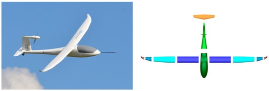
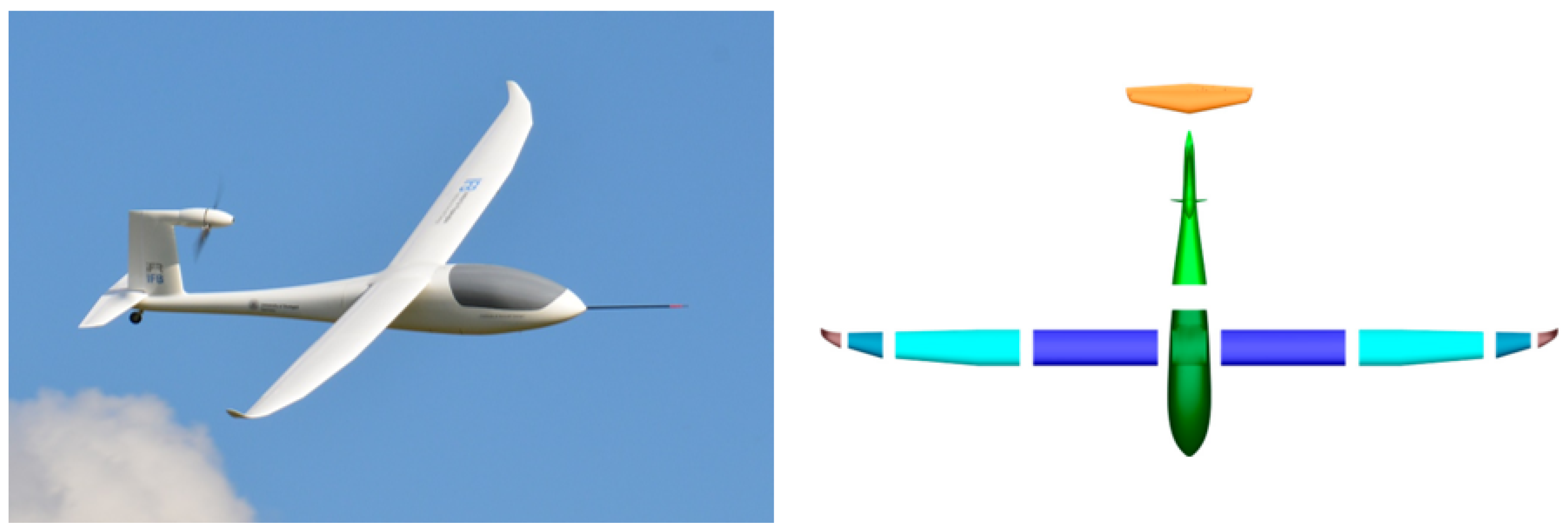
The e-Genius-Mod is a 33.3% scaled model of the full-electric motor glider e-Genius, both developed at the Institute of Aircraft Design (IFB) at the University of Stuttgart. Its modular design enables the e-Genius-Mod to serve as a SFD for investigating novel aircraft design concepts and technologies. The development of the baseline configuration is described in Bergmann et al. [2], scaling the full-scale e-Genius in accordance with the Froude number. Through its modular structure, individual segments of the fuselage or wings can be easily replaced or adapted. An on-board autopilot system with a variety of measurement equipment enables the test platform to be used as a “flying wind tunnel” collecting a wide range of parameters needed for scientific analysis. Examples include a multi-hole-probe (MHP) for atmospheric measurements and a custom-made load cell used for thrust measurements as described in Bergmann et al. [2,16]. The baseline configuration of the e-Genius-Mod and the structure of its modular design is shown in Figure 1.
Figure 1.
e-Genius-Mod in flight (left) and modular design [2] (right) (Source: IFB).
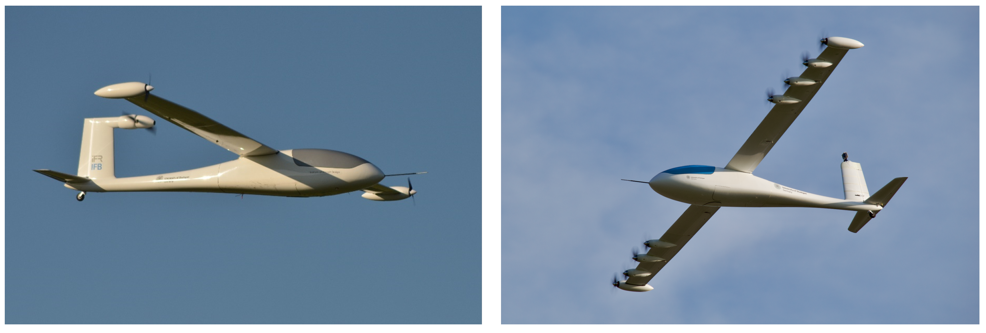
The e-Genius-Mod has been modified multiple times as part of various research projects, testing a variety of novel aircraft configurations in a real-world environment. Starting in 2018, the ELFLEAN project investigated the effects of WTP by replacing the outer wingtip sections of the e-Genius-Mod with wingtip pods. By installing an additional thrust measurement system inside the pods, the influence of the WTP on the wingtip vortex and subsequently the drag polar was quantified [17].
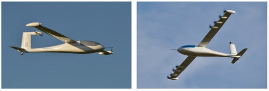
In the follow-up project VELAN, the e-Genius-Mod was equipped with eight propellers along the leading edge for a multidisciplinary investigation of DEP. In addition, the main propeller mounted on the vertical stabilizer was removed, and the vertical tail plane (VTP) sectioned into five pieces. The latter was done to demonstrate the ability of DEP to maintain yaw stability and control while sequentially reducing the size of the VTP for drag reduction. The configuration of the research projects ELFLEAN and VELAN can be seen in Figure 2.
Figure 2.
e-Genius-Mod ELFLEAN configuration (left) and VELAN configuration (right) (Source: IFB).
1.2. Research Objective
The objective of this study is the implementation and experimental investigation of an energy harvesting system into the SFD e-Genius-Mod as part of the LuFo VI-3 research project eMission at the University of Stuttgart. Wind tunnel experiments are conducted to investigate the performance of the EHP for two pitch settings reported in the literature: “Windmilling” and “Opposite Pitch” (see Section 1). The wind tunnel experiments are conducted using the EHP wingtip pod hardware for integration on the SFD e-Genius-Mod, enabling a validated performance assessment under representative integration conditions. The investigation aims to determine the power output as reference EHP performance data for subsequent free flight tests.
2. Methods
In order to evaluate the performance of the EHP and the energy harvesting system both in-flight and on a wind tunnel test rig, the composition of the overall system and subsequent integration are described within the following subsections. In Section 2.1, the implementation into the SFD e-Genius-Mod is presented, succeeded by the wind-tunnel test rig in Section 2.2.
2.1. EHP Integration into the e-Genius-Mod
To better understand the overall context of the EHP integration into the SFD e-Genius-Mod, the overall modifications performed on the SFD are briefly explained. On this basis, the structural integration into the SFD as well as implementation into the on-board measurement system are presented.
2.1.1. Overall Modification of the SFD e-Genius-Mod
The SFD e-Genius-Mod was modified in order to investigate various technologies, including the EHP. Based on the DEP configuration used for the VELAN project (see Figure 2), a new wing and propulsion system was designed and integrated. The wing design is based on a single trapezoidal shape with a sweep angle of 0°, keeping the same airfoil from previous versions. To ensure a sufficient safety margin of ground clearance for the wingtip-mounted EHP during take-off and landing, the dihedral was increased by 2° to 3.5°. By taking advantage of the positive effects of DEP on the wing lift distribution, as described in the previous section, the wing area was reduced by approximately 15% compared to the e-Genius-Mod baseline. The increase in the effective maximum lift coefficient due to DEP allows a reduction of the wing area while maintaining the same stall speed requirement in the sizing process. The wing is made of a carbon-fiber-reinforced composite structure consisting of the wing shell, main spar, auxiliary spar, and ribs. Ailerons and flaps are attached as elastic flaps, requiring no additional rudder hinge mechanisms, saving additional weight and complexity. The technical data for the configuration can be found in Table 1.
Table 1.
Technical data of the e-Genius-Mod in eMission configuration.
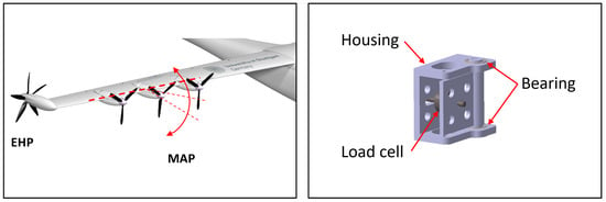
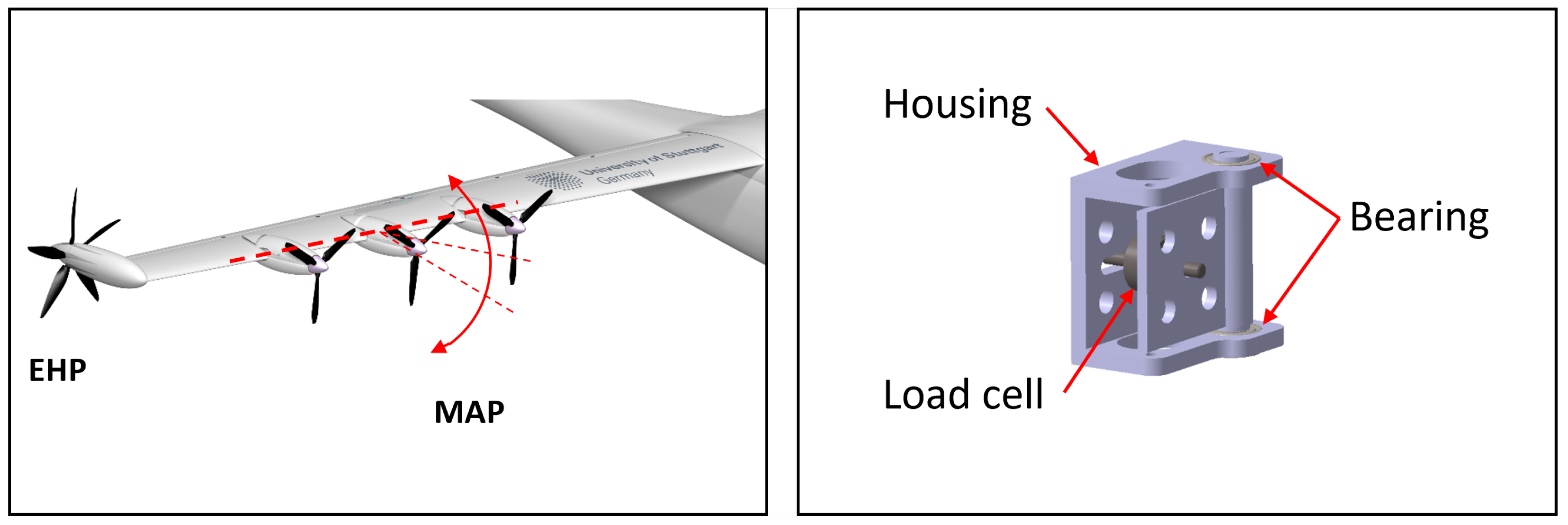
In contrast to the previous VELAN configuration, the DEP system consists of two different types: The inner propellers along the leading edge are designed as so-called mission-adaptive propellers (MAPs). The main difference between the MAP and the DEP used in the VELAN configuration is that the inclination angle of the MAP can be adjusted in relation to the wing chord line. This allows for adjusting the propeller disk plane in accordance with a flight phase, e.g., take-off, climb, and cruise. An in-flight investigation into the influence of the inclination angle to the aircraft characteristics and required energy will be conducted within further flight tests.
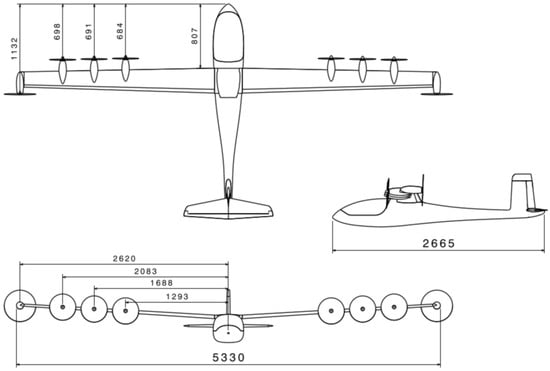
At the wingtips, EHPs are installed, intended for the in-flight investigation of its practicality as laid down in Section 1. The use of WTTs was dismissed, despite a higher expected efficiency [12], in order to enable the investigation into energy harvesting during the approach and landing phase. As recommended by Firnhaber-Beckers et al. [12], a pusher configuration was selected for the EHP, which consists of 5-bladed Ramoser SG16D propeller with a diameter of . For reasons of weight and complexity, the pitch settings will be adjusted manually before each flight. A three-sided view of the e-Genius-Mod in the eMission configuration is displayed in Figure 3.
Figure 3.
Three-sided view of the eMission configuration.
2.1.2. Structural Integration of the EHPs
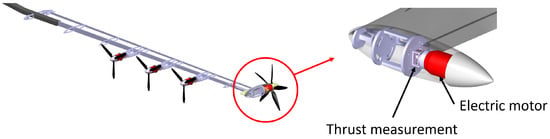
The EHP unit, consisting of the propellers, hub, and electric motor, is mounted directly to a spar housed inside a pod at the wingtip. In addition, a thrust measurement is installed between the motor and spar. A compact thrust measurement system is implemented, based on a concept developed by Kolb [18]. The system consists of a housing and a folding mechanism in which a load cell is located. A load cell with a nominal force of 100 N is mounted, which is above the maximum thrust of the propulsion system. The hinge axis is installed vertically so that no high loads are transferred to the load cell, for example, during landing. The structural design of the wing and the wingtip pod of the EHP are shown in Figure 4. The integration of the MAP and the composition of the thrust measurement system are shown in Figure 5.
Figure 4.
Structure of the wing and implementation of the EHP.
Figure 5.
Adjustment of the MAP (left) and structure of the thrust measuring system (right).
2.1.3. System Architecture and Measurement System
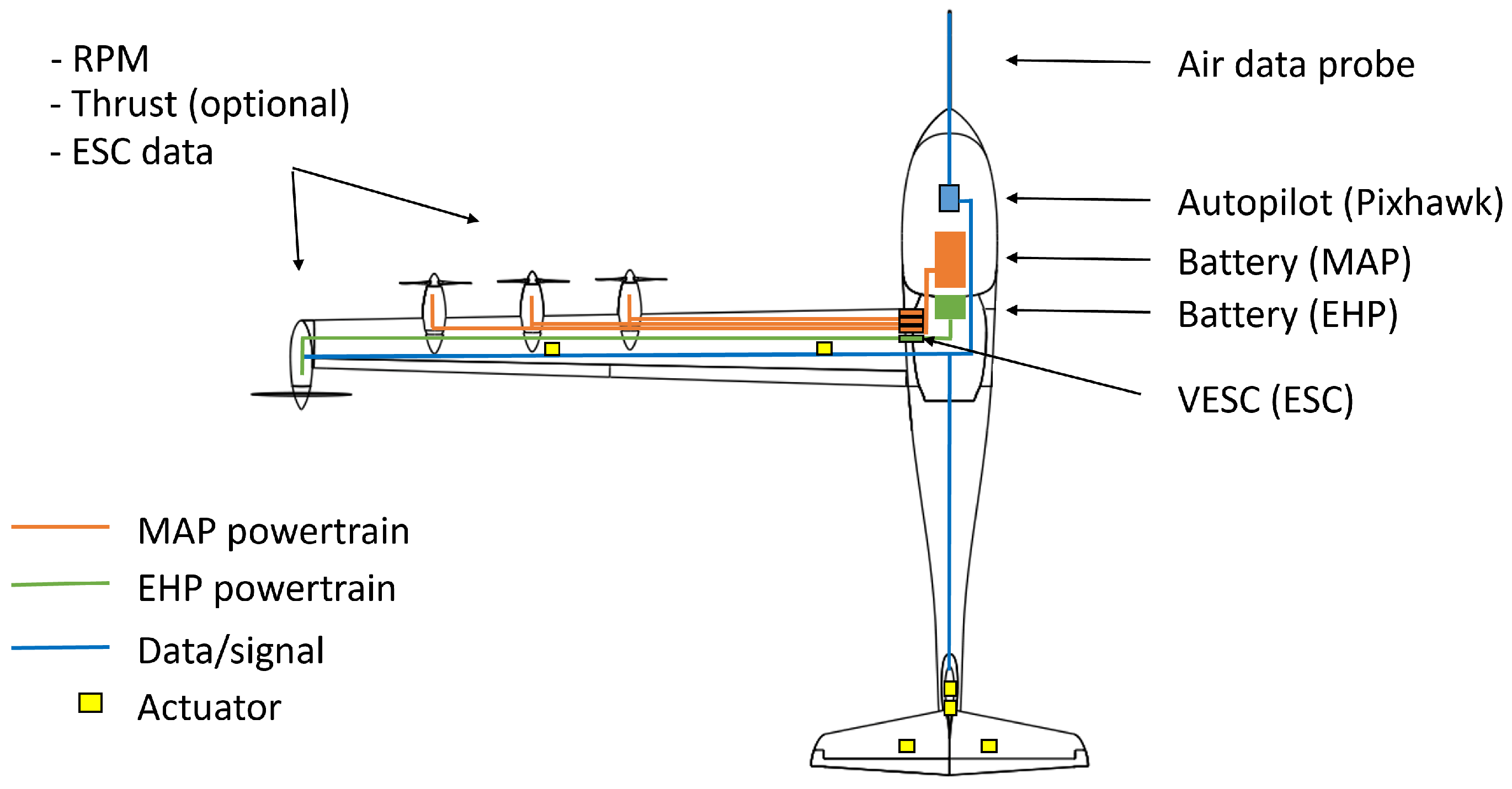
The system consists of two separate powertrains, one for the MAP and EHP each, enabling one to control both separately. This divide is crucial for two reasons: first, the EHPs take on a different role during approach and landing by creating additional drag to enable the MAP to maintain a higher power setting. Second, the EHPs are designed as part of a energy harvesting system, recharging the connected batteries while breaking. A crucial part for implementing this energy harvesting powertrain into the SFD is the ability of the electronic speed controller (ESC) to recuperate energy from the motor into the battery. Most ESCs used in radio controlled model aircraft do not posses this function, merely the possibility to stop the motor completely. As part of a bachelor’s thesis at the IFB, Mentzer [19] tested a suitable ESC, namely the VESC MK6VI [20], for recuperation during breaking. Since only the EHPs require an ESC with the possibility of recuperation, the VESC are solely connected to the EHP. The MAP, on the other side, are operated using conventional ESCs.
Besides controlling the state of the motor, the VESC is also capable of logging various parameters, most importantly the electric voltage and current. To simplify the subsequent analysis after flight tests, the data are transferred to a centralized unit, in this case a Pixhawk flight control unit. Other sensors needed for an in-flight evaluation are either integrated into the Pixhawk itself, or also connected via a data bus. A list of the most prominent measurement systems can be found in Table 2. Besides functioning as a data logger, the Pixhawk mainly serves as a flight controller for an automated flight along a predetermined path.
Table 2.
Measurement equipment on-board the e-Genius-Mod in eMission configuration.
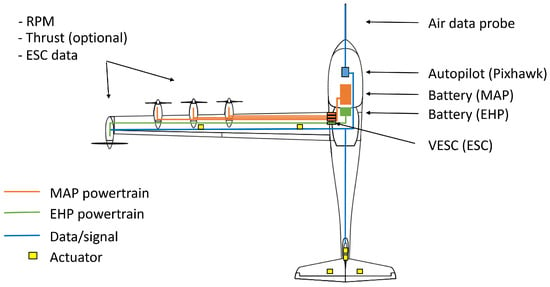
An overview of the system architecture is shown in Figure 6. Both the ESCs for the MAP and the VESC for the EHP are located within the fuselage of the e-Genius-Mod. The batteries are also located slightly more to the front, utilizing the mass to control the center of gravity. The Pixhawk flight control unit is located between all measurement systems.
Figure 6.
Schematic overview of the components and systems within the SFD.
2.2. Wind Tunnel Tesing of the Energy Harvesting System
Before conducting in-flight tests of the energy harvesting system, wind tunnel tests of the energy harvesting systems were conducted in collaboration with the Institute of Aerodynamics and Gas Dynamics (IAG) at the University of Stuttgart. The medium-sized wind tunnel at the IAG was used to test the functionality of the system, evaluate the performance under controlled conditions, which is both the scope of this section, and beyond that to validate aerodynamic simulations.
2.2.1. Wind Tunnel Model
The wind tunnel model consists of the outer section of the eMission wing on the right hand side, including the wingtip propeller in pusher configuration. MAP were not implemented in this setup because the primary focus was on investigating the EHP and the energy harvesting system. The model is at the same scale as the scaled flight demonstrator, which allows the results to be transferred directly to the flight test application.
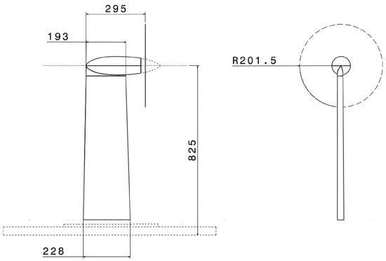
The wing segment has a length of and is geometrically identical to the wing of the SFD. No ailerons have been implemented, as the wind tunnel test is not supposed to cover any control surface inputs. Aileron deflections can influence the lift distribution as well as the wing–propeller interaction, so the present investigation is representative for steady flight phases in which no significant roll corrections with the ailerons are performed. The wingtip nacelle of the modified scaled flight demonstrator is installed directly on the wingtip of the segment. The arrangement of the components inside the wingtip nacelle is identical to the arrangement in the upcoming flight tests. These consist of an electric motor, the propeller, the RPM sensor, and the thrust measurement system. The wing segment is fastened to the wind tunnel floor using a mounting frame. The dimensions of the wind tunnel model are shown in Figure 7.
Figure 7.
Dimensions of the wind tunnel model. All values are displayed in mm.
2.2.2. Experimental Setup
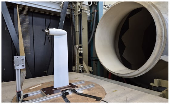
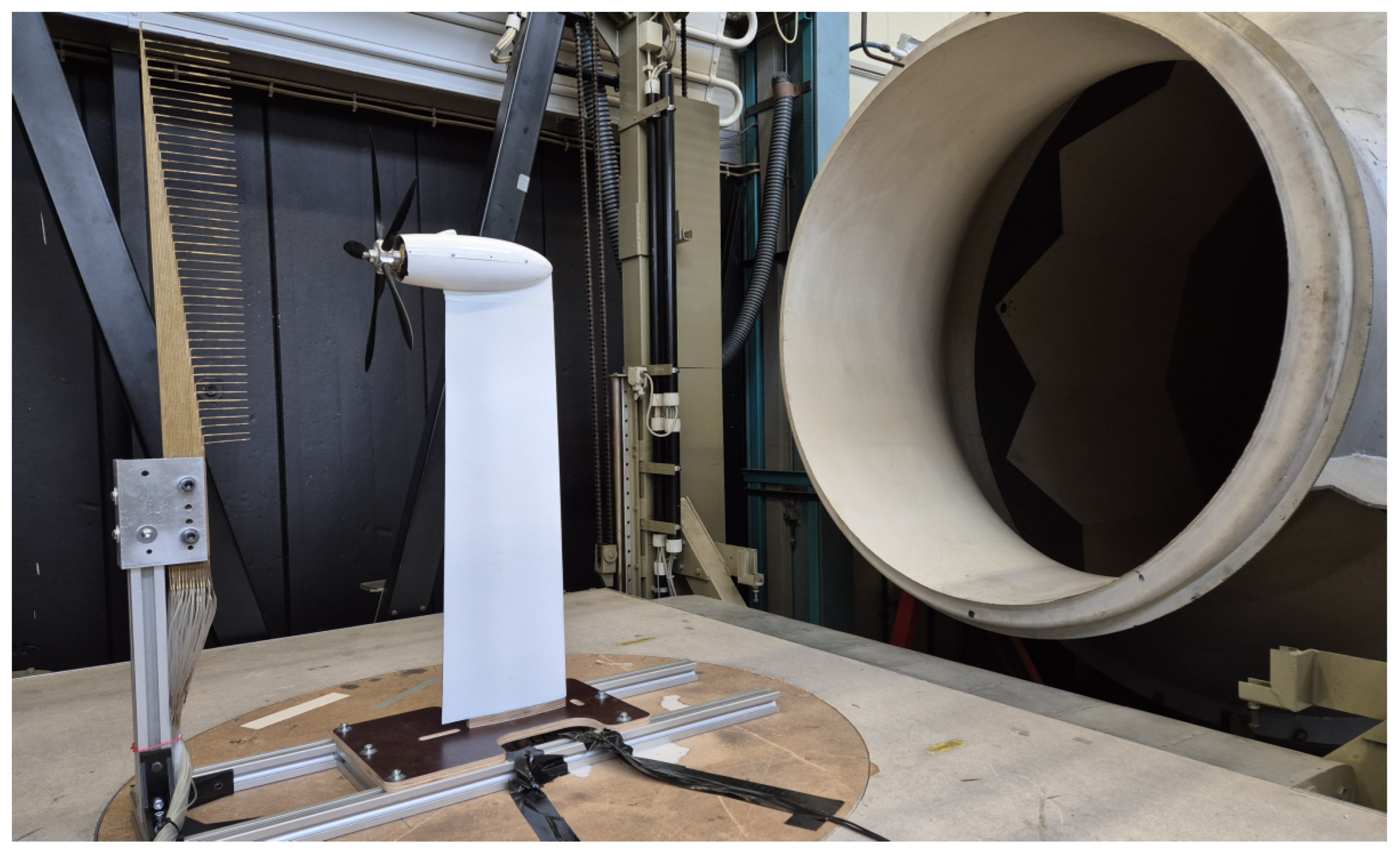
The wind tunnel is a circulating Göttinger type with a free jet measuring section. The diameter of the nozzle during the tests was . The nacelle was positioned in the center of the circular jet cross section, mounted on a rotating plate so that the angle of attack could be adjusted.
Inside the wingtip pod, the thrust measurement system was installed with a rotation angle of 90° in contrast to the installation position in flight. Since the thrust measurement system is based on a hinged mechanism, the orientation of the system has an effect on the thrust measurements (see Figure 5). Cables with a cross section of and a length of were used to connect the electric motor with the VESC, which corresponds to the configuration in the original wing. The electric motor was controlled through the VESC via a PWM signal. Power was supplied by a 4S LiPo battery. The propeller wake was additionally measured for further the aerodynamic investigations by placing a wake rake behind the model. The positioning of the model, the wake rake, and the overall setup in the wind tunnel are shown in Figure 8.
Figure 8.
Experimental setup in the wind tunnel.
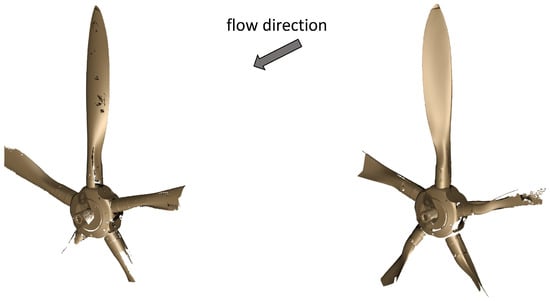
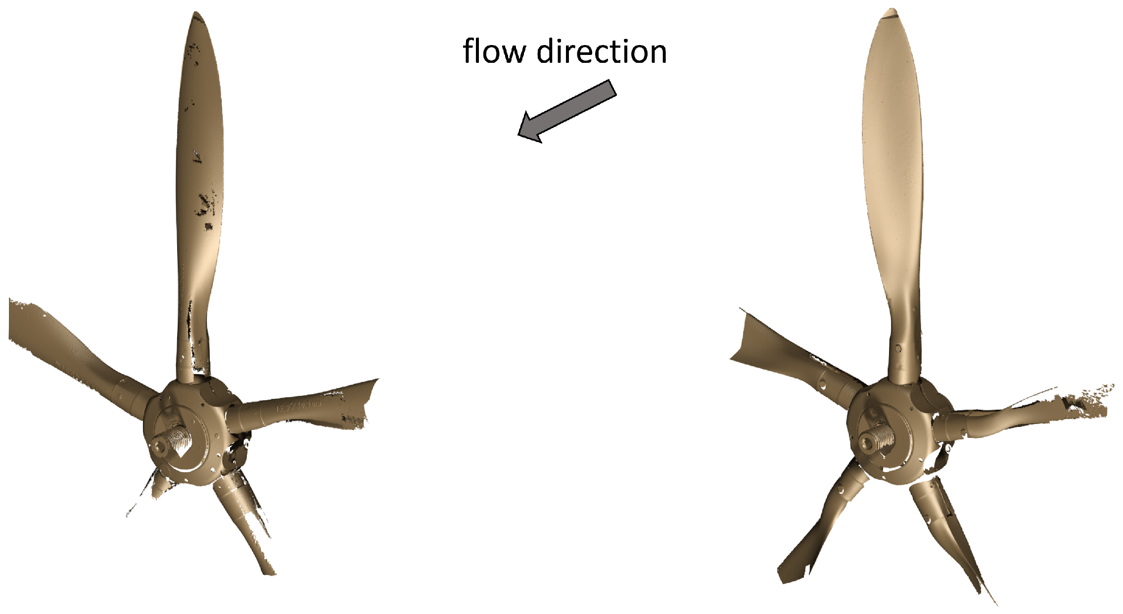
For the experiment, the 5-blade propeller of the EHP was adjusted for the two operation modes: Windmilling and Opposite Pitch. To determine the exact pitch setting, the rotor blade geometry, including the hub, was previously determined using an optical 3D scanner. As the propeller geometry is twisted along its length, the pitch values at 70% of the propeller radius are used as a reference. In the operation mode Windmilling, the propeller pitch is ; for Opposite Pitch, . With regard to the direction of flight, clockwise rotating propeller blades were used. The propeller geometries of the pitch settings Opposite Pitch and Windmilling are shown in Figure 9.
Figure 9.
Results of the 3D-scan: Propeller geometry with the pitch settings Opposite Pitch (left) and Windmilling (right).
For the test, freestream velocities of and , which represent the expected flight speeds, were set inside the wind tunnel. Two sets of tests were then conducted, starting with individual functionality tests, during which the wind tunnel was turned on, causing the propeller to reach a certain rotational speed due to the incoming airflow. Following thereafter the recuperation tests of the EHP were executed, reducing the rotational speed in steps to set specific advance ratios. This was achieved by setting the rotational manually to RPM values displayed by both the VESC and the additional RPM sensor in the wingtip pod.
3. Results
Wind Tunnel Test Results
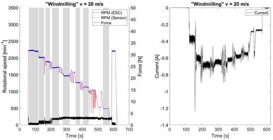
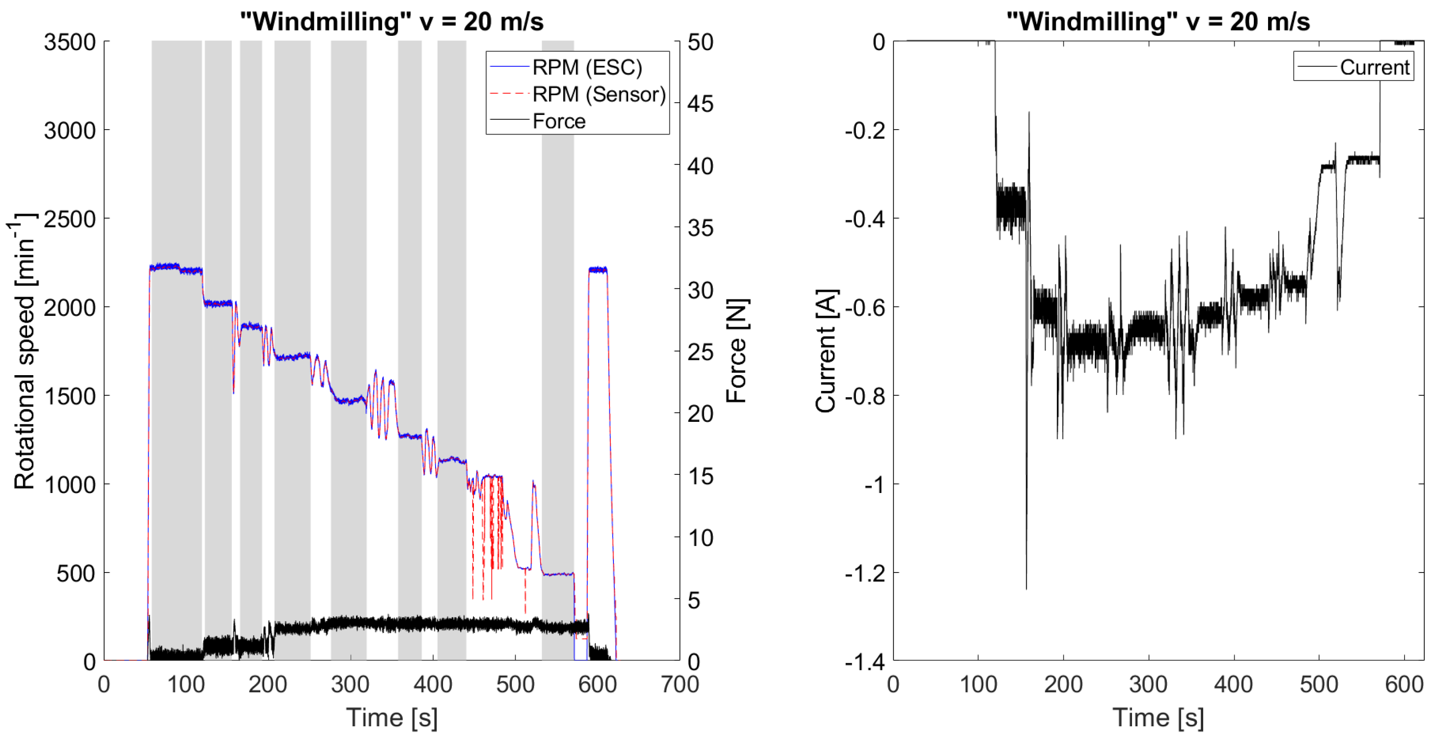
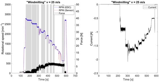
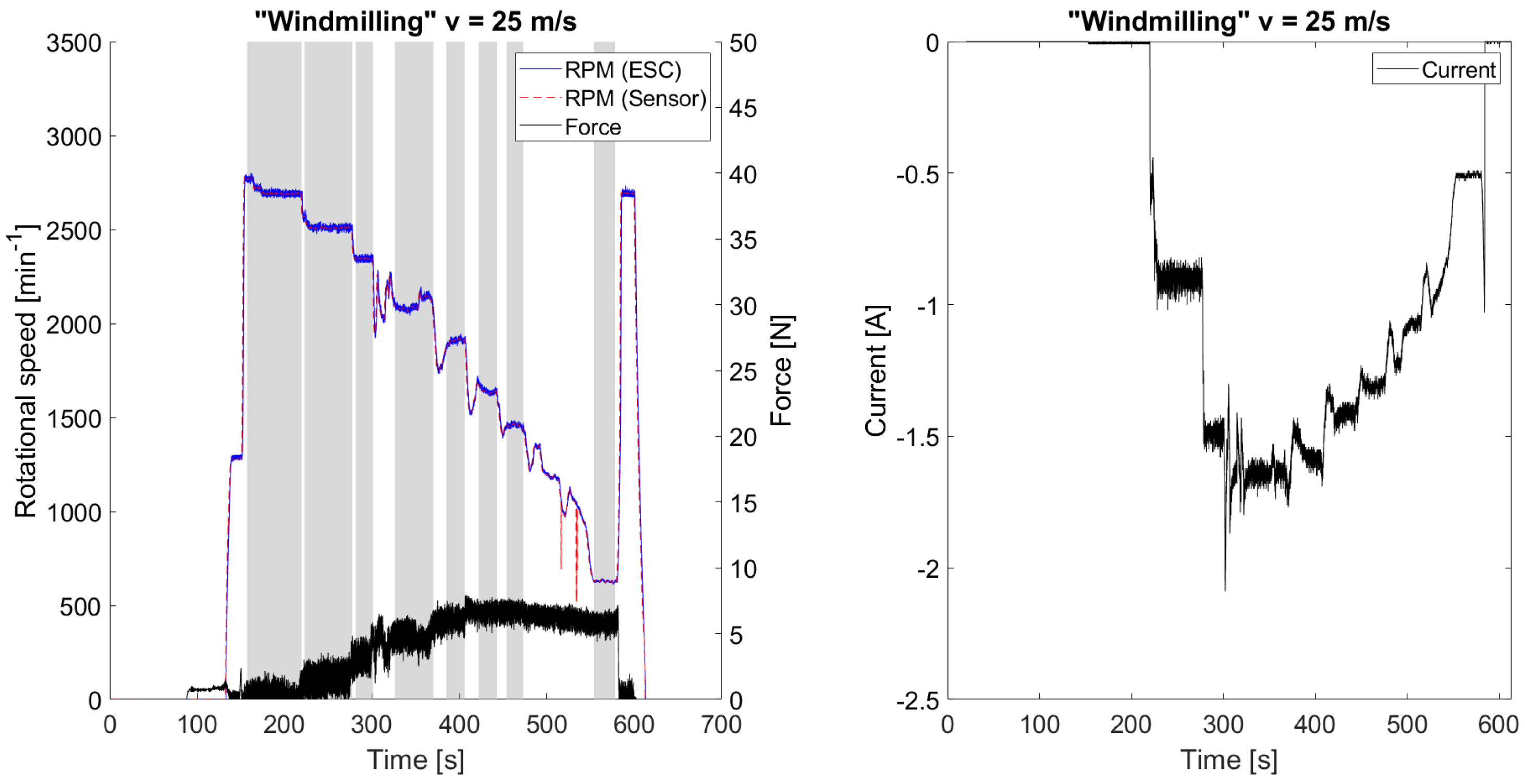
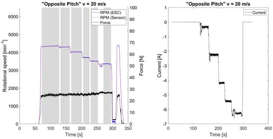
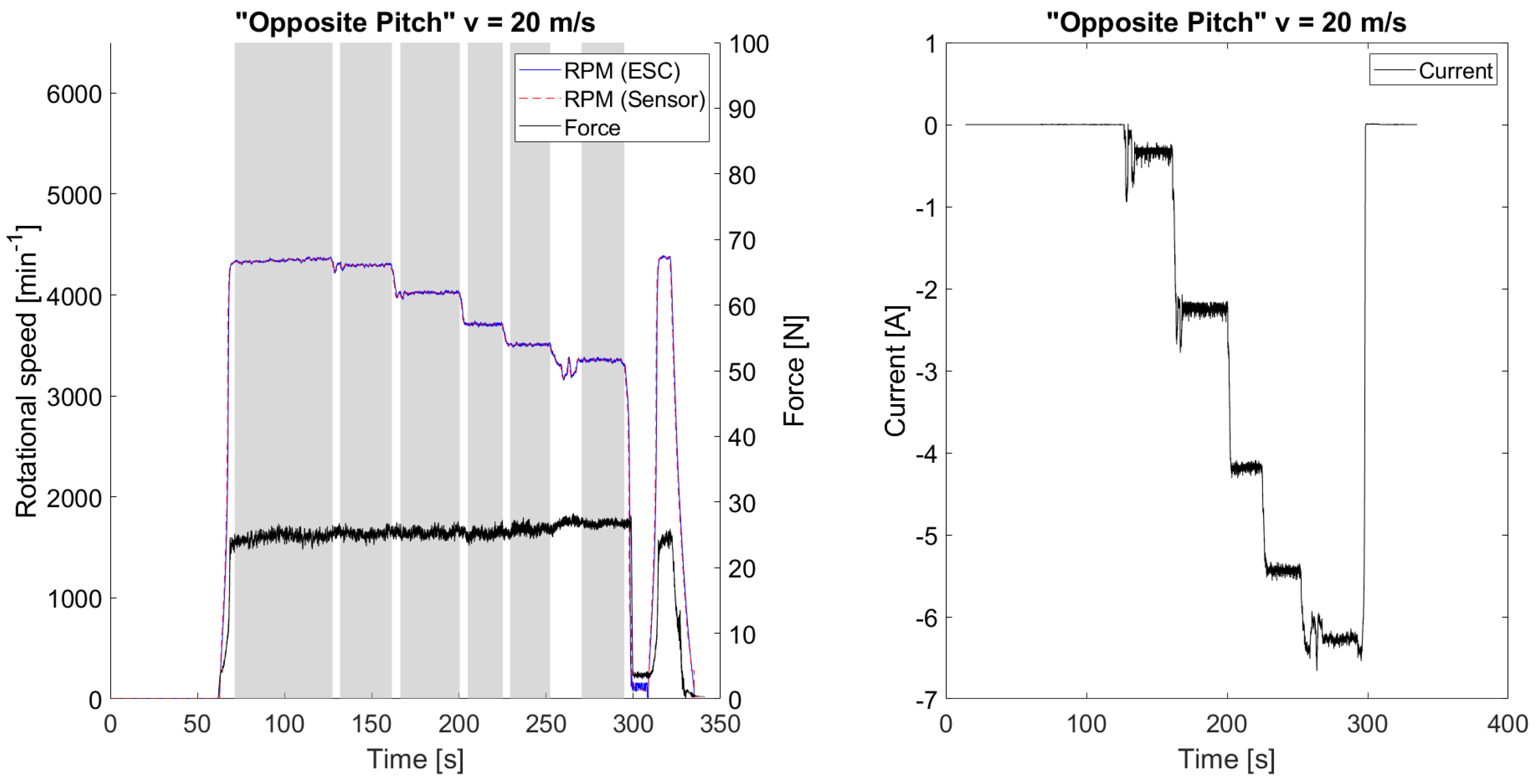
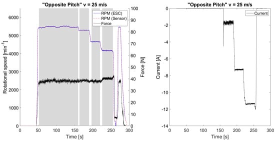
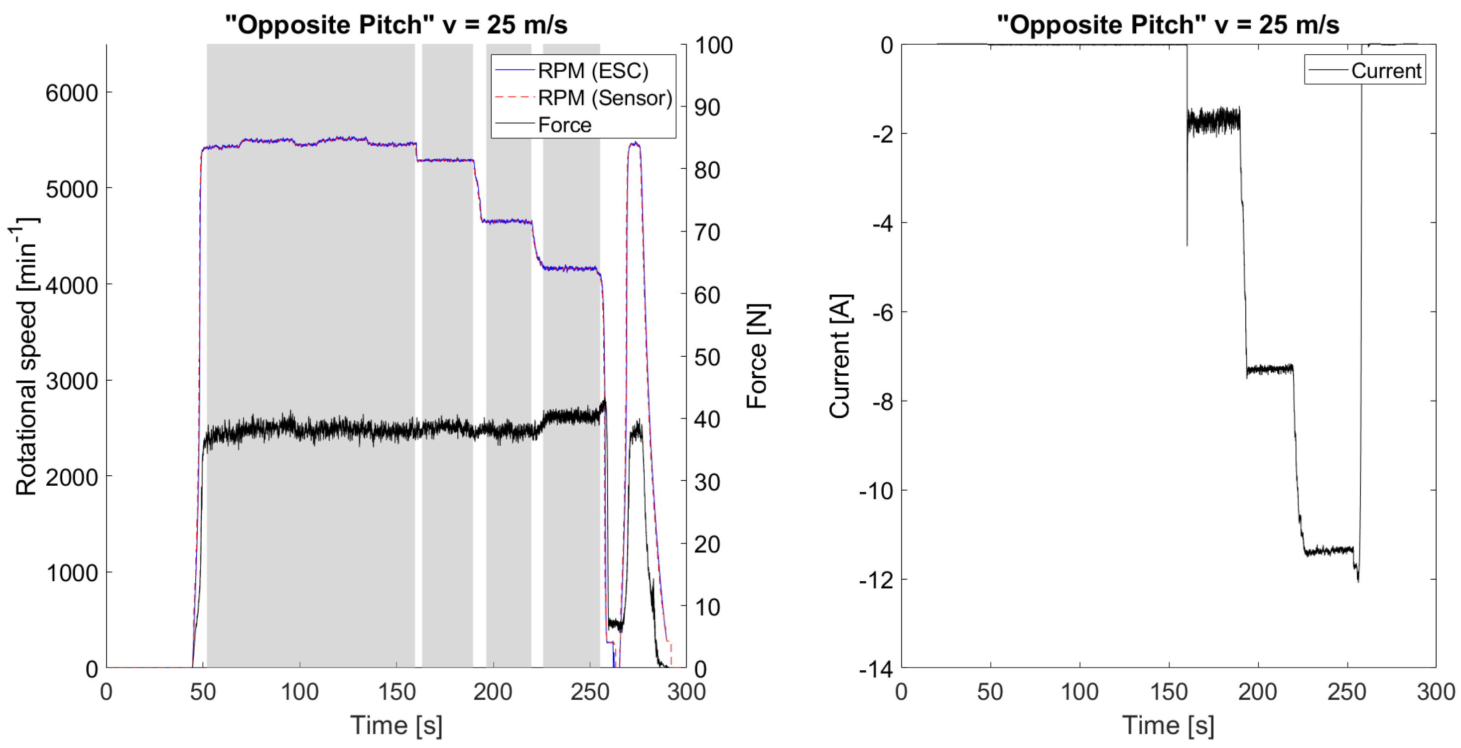
The results in the Windmilling and Opposite Pitch modes at freestream velocities of and are shown below. The data from the ESC, thrust measurement, and rotational speed measurement were synchronized via the increase during propeller ramp-up. Voltage, current, and electrical revolutions per minute (eRPM) were measured by the VESC. The eRPM was corrected to RPM based on the number of pole pairs of the electric motor. The thrust measurement data were recorded at 200 Hz and plotted using a moving average over the last 50 data points. Due to the orientation of the load cell in the thrust measurement system, positive thrust values represent forces acting opposite to the direction of flight. The angle of attack of the wing model was zero degrees. The various operating points were set by adjusting the rotational speed. Each operating point was maintained under steady-state conditions. Mean values were computed for each rotational speed stage, using the time-resolved measurements of voltage, current, rotational speed and force. These stages are highlighted in gray in the figures. For each stage, the combined uncertainty was evaluated from statistical uncertainties and additional contributions from the measurement equipment. The measurement uncertainty is reported at a 95% confidence level (). Since no manufacturer specifications for the measurement uncertainty of the VESC are available, a conservative assumption of a relative error of 5% for voltage and current measurements was used. For the thrust measurement system, a conservative assumption of a relative error of 10% was used, based on static load tests in which the maximum deviation reached this level. For derived quantities, such as electrical power, uncertainty propagation was performed using Gaussian error propagation.
Figure 10 and Figure 11 show the results of the Windmilling mode. The mean rotational speeds at which the propeller is not actively braked or driven are 2213 RPM at and 2705 RPM at . The speed was reduced in stages to approximately 500 RPM. A mean current of up to −0.68 A at and −1.6 A at were measured. A minimum rotational speed limit is observed, below which the motor is unable to maintain continuous operation. Reducing the rotational speed below this threshold leads to a motor stop. This can be seen in Figure 10, Figure 11, Figure 12 and Figure 13 at the drop in RPM, followed by a return to the initial speed without recuperation.
Figure 10.
Results of Windmilling mode at .
Figure 11.
Results of Windmilling mode at .
Figure 12.
Results of Opposite Pitch mode at .
Figure 13.
Results of Opposite Pitch mode at .
Figure 12 and Figure 13 show the results of the Opposite Pitch mode. In this mode, the maximum currents were measured at the lowest RPM levels. In the last stage, the mean current was −6.3 A at and −11.4 A at . The cut-in wind speed was determined experimentally for both pitch settings by slowly increasing the freestream velocity. For Opposite Pitch, this was approximately 19.5 m/s; for Windmilling, approximately 11 m/s.
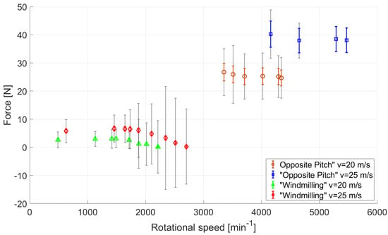
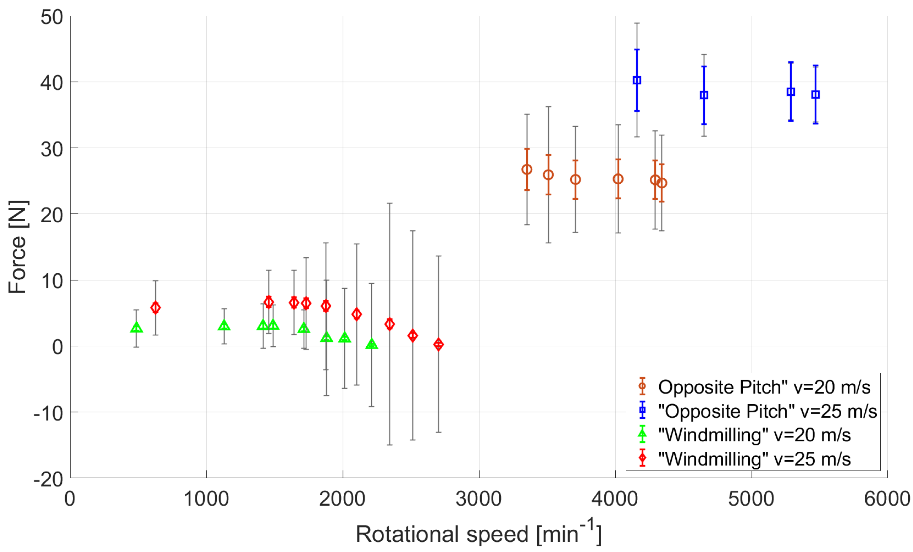
The mean force for the various rotational speed settings and operating modes is shown in Figure 14. The force measurements show significant fluctuations during each stage, resulting in a large standard deviation of the raw signal. This behavior might be influenced by a combination of structural vibrations, ESC induced oscillations and aerodynamic effects. The time-averaged values remain stable and show consistent trends at all stages, indicating that the thrust measurement is suitable for qualitative analysis of the trend and performance behavior.
Figure 14.
Mean Force with standard deviation (gray) and measurement uncertainty (colored bars).
The largest standard deviation of 8% in rotational speed was observed in Windmilling mode at 1415 RPM at and 1731 RPM at . For all other stages, the standard deviation of the rotational speed is less than 2%. The maximum mean forces are achieved in Opposite Pitch mode. In this mode, the maximum mean force is 40.3 N at and 26.7 N at . In the Windmilling mode, the maximum mean force is 6.7 N at and 3.1 N at .
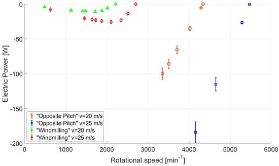
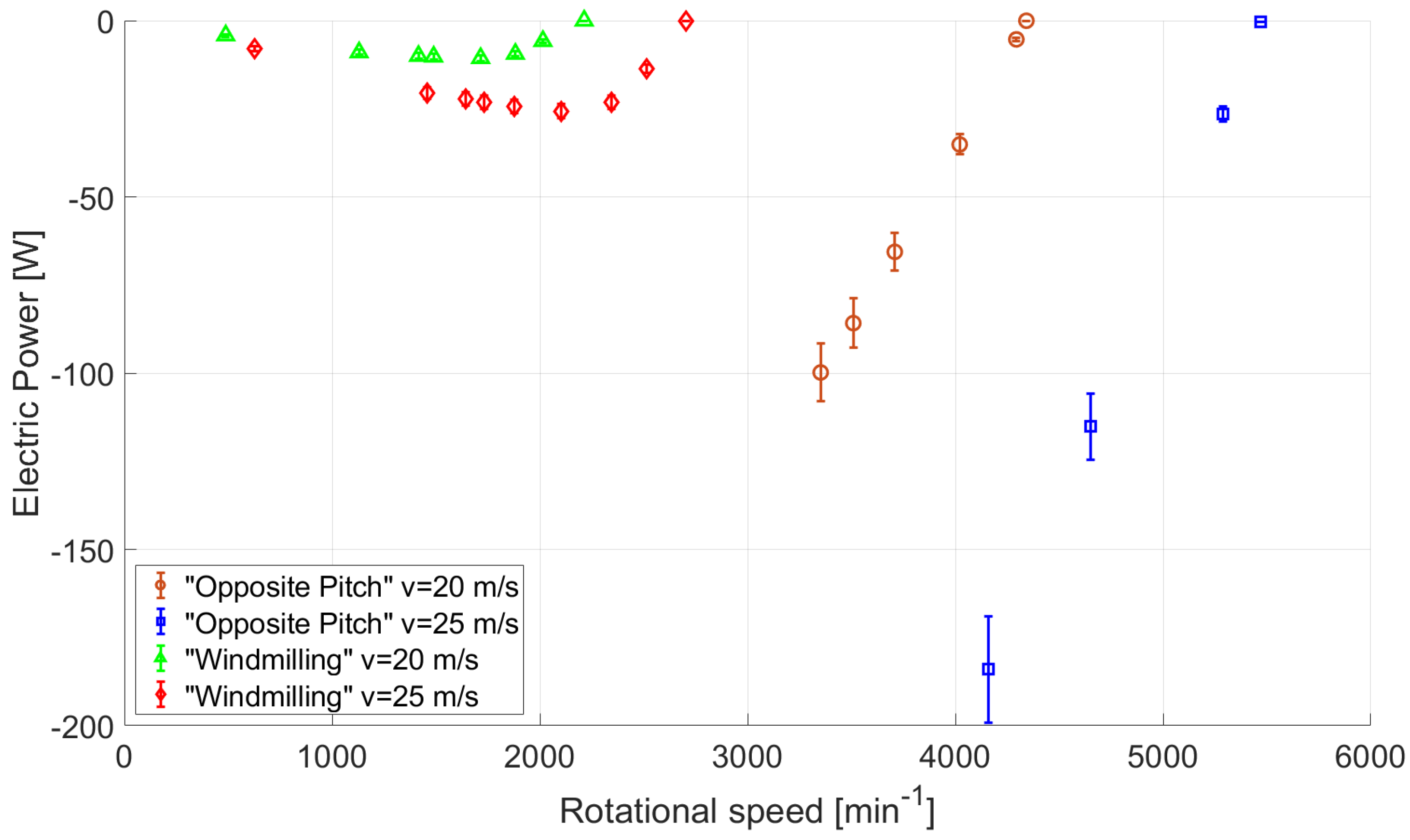
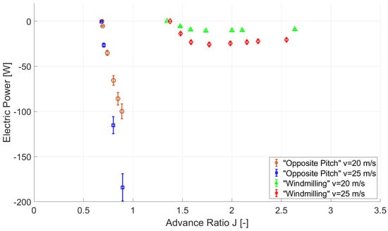
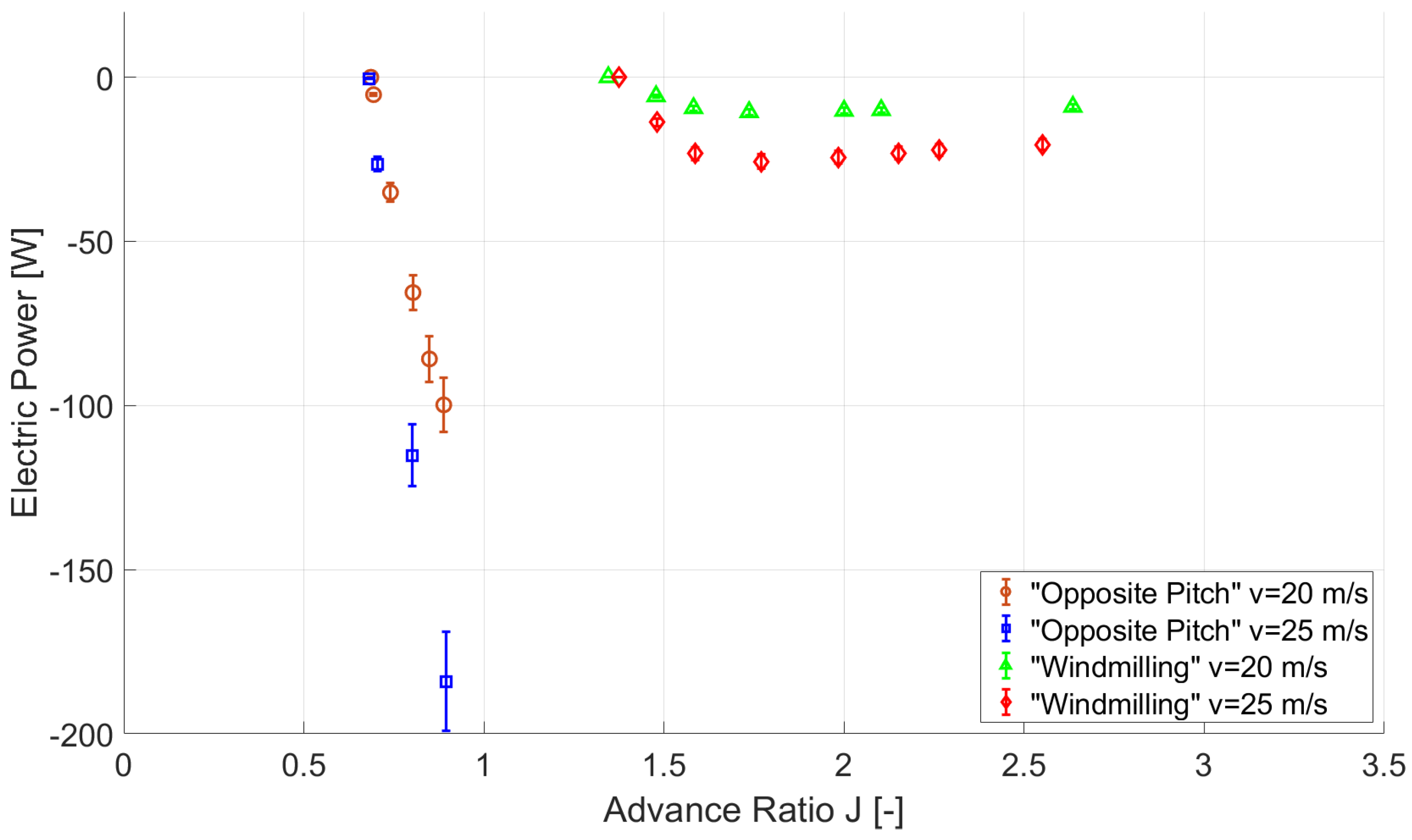
The electrical power is calculated based on the voltage and current measurements at the VESC. For the evaluation of the performance, the values were averaged in the stages at which the rotational speed was set to a constant value. Figure 15 shows the electrical power output of the examined rotational speed stages, with uncertainty bounds indicated. In Windmilling mode, the electrical power output increases to a maximum and subsequently decreases with further reduction in rotational speed. The maximum is −10.6 W for and −25.7 W for . In Opposite Pitch mode, the electrical power output increases as the rotational speed decreases. It was not possible to reduce the rotational speed any further while maintaining a constant RPM level. The maximum electrical power is −184 W at at 4170 RPM. At the maximum electrical power is −100 W at 3350 RPM. Figure 16 shows the electrical power output in relation to the advance ratio, including uncertainty bounds. The advance ratio is calculated as the ratio of the freestream velocity to the product of rotational speed and propeller diameter.
Figure 15.
Electric power output in relation to the rotational speed.
Figure 16.
Electric power output in relation to the advance ratio.
4. Discussion
Compared to other scaled flight demonstrators, e.g., the e-Genius-Mod in VELAN configuration, the modification presented in this work shows the implementation of an energy harvesting powertrain. This enables the investigation of energy regeneration in free flight tests. The propeller pitch of the EHP can be manually adjusted to the required pitch before operation. This allows for both Windmilling and Opposite Pitch modes. With regard to flight testing, this means that only one pitch setting can be set and examined per flight. In Windmilling mode, the wingtip propeller can additionally be used to generate positive thrust. In Opposite Pitch mode, the wingtip propeller can only be used as EHP for energy regeneration (negative thrust), while positive thrust can only be provided by the MAP.
The function of the energy harvesting system was investigated and demonstrated in the wind tunnel. Various propeller rotational speeds and advance ratios, respectively, were tested for recuperation at various flow velocities representative for flight conditions. The general function of an energy harvesting propeller or propellers with negative thrust has already been investigated in previous studies such as [15]. In the investigation, the focus is on verifying a system that is installed in an SFD for the use in free flight tests.
In Opposite Pitch mode, the mean force and current were higher for the installed propeller pitch settings corresponding to the numerical investigations by Firnhaber-Beckers et al. [21]. Looking at the electrical power, it can be seen that, in the Opposite Pitch mode, the power output is higher. Within the tested operation points, the regenerated power increases as the rotational speed decreases. For Opposite Pitch mode, −184 W and −100 W also represent the maximum power that can be regenerated at the corresponding freestream velocity, as a lower rotational speed could not be set with the ESC. For Windmilling mode, −10.6 W and −25.7 W were achieved as maximum. Here, a further reduction in the rotational speed was possible, which in turn led to lower power output.
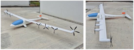
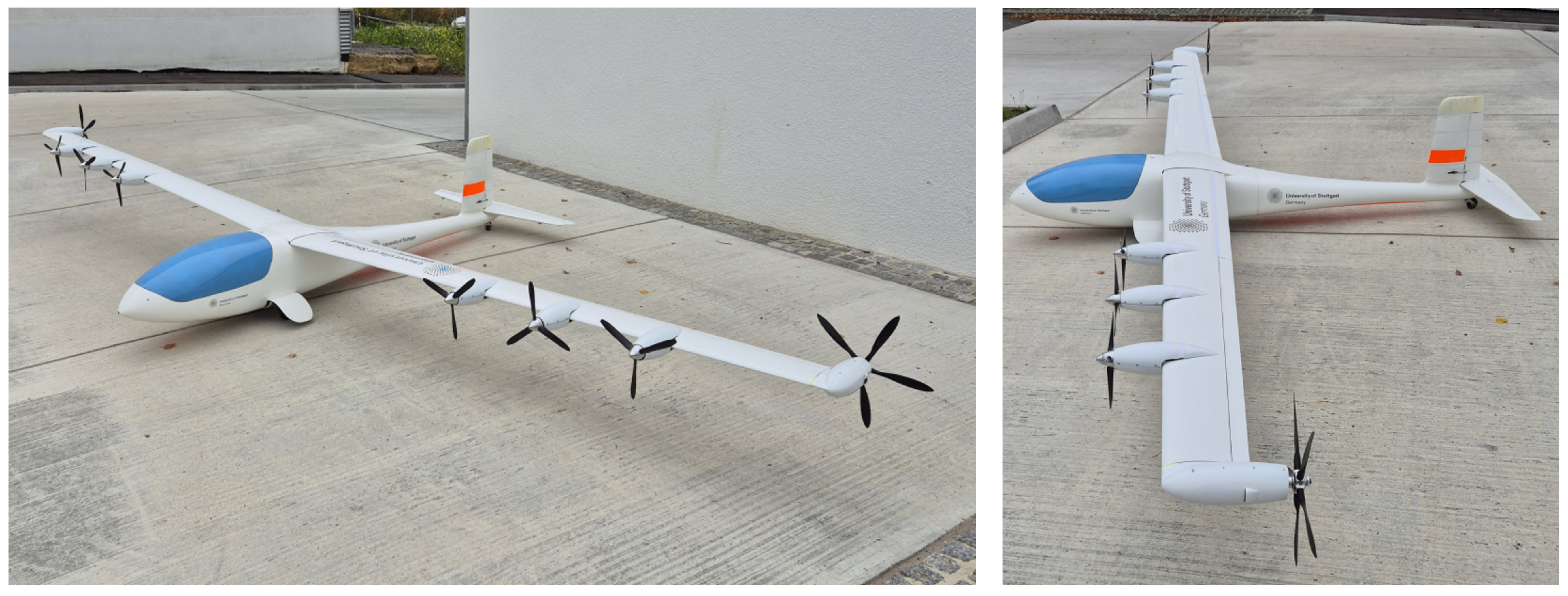
To apply the findings to a broader context, several aspects should be considered. The study is focused on the experimental characterization of the energy harvesting system in the wind tunnel to investigate the link between power output and propeller pitch settings. Furthermore, no scaling effects were investigated within the scope of this work. When transferring the results to a full-scale aircraft, scaling effects must be taken into account. The transfer to larger aircraft and the evaluation of the benefits are the subject of future research. A comprehensive evaluation of energy recovery efficiency relative to total aircraft power consumption will be addressed in future flight tests, enabling performance assessment under real flight conditions. Future research will focus on conducting free-flight tests with the modified SFD. For this purpose, the energy harvesting system has already been integrated into the SFD, which is shown in Figure 17. During the flight tests, various descent angles will be tested in Windmilling and Opposite Pitch mode. In addition, different thrust settings of the MAP will be examined.
Figure 17.
Scaled flight demonstrator e-Genius-Mod in the eMission configuration.
5. Conclusions
The scaled flight demonstrator e-Genius-Mod was modified for energy harvesting propellers mounted on the wingtips and mission-adaptive propellers along the wing. While previous studies have focused on investigating DEP with SFDs, the concept described here offers a way of implementing a novel energy harvesting powertrain to investigate and demonstrate energy harvesting in-flight. The function was tested experimentally, and at the same time, the regenerated energy and thrust that can be expected under representative flight and integration conditions were quantified. In Windmilling mode, the maximum electrical power output is −25.7 W at a negative thrust of approximately 6 N. In Opposite Pitch mode, the values were significantly higher, with a maximum electrical power of −184 W and a negative thrust of 40 N. This corresponds to up to seven times higher regenerated power in Opposite Pitch mode. The regenerated power can be adjusted via the rotational speed in both operation modes. In combination with the mission-adaptive propellers, this enables the investigation of mission specific propulsion settings with the SFD, e.g., during the approach or descent phase.
The required functionalities of EHP are implemented in the scaled flight demonstrator e-Genius-Mod. It was experimentally verified that the new energy harvesting system operates as intended and can be used in future flight tests. As a further outlook, flight tests are planned to investigate and evaluate the performance of energy harvesting propellers and mission-adaptive propellers under real conditions in free flight tests.
Author Contributions
Conceptualization, A.K., E.J.N., and J.D.; methodology, A.K., E.J.N., and J.D.; formal analysis, A.K.; investigation, A.K.; data curation, A.K.; writing—original draft preparation, A.K. and E.J.N.; writing—review and editing, D.P.B. and A.S.; visualization, A.K.; software, A.K.; supervision, D.P.B. and A.S.; funding acquisition, D.P.B. and A.S. All authors have read and agreed to the published version of the manuscript.
Funding
The authors gratefully acknowledge the Federal Ministry for Economic Affairs and Energy (BMWE) for funding this work in the framework of the research project eMission (FKZ: 20M2248).
Data Availability Statement
The raw data supporting the conclusions of this article will be made available by the authors on request.
Acknowledgments
The wind tunnel tests were conducted in collaboration with the Institute of Aerodynamics and Gas Dynamics (IAG) at the University of Stuttgart as additional tests within the scope of the research project.
Conflicts of Interest
The authors declare no conflicts of interest.
Abbreviations
The following abbreviations are used in this manuscript:
| CAN | Controller Area Network |
| DEP | Distributed Electric Propulsion |
| EHP | Energy Harvesting Propeller |
| eRPM | Electrical Revolutions per Minute |
| ESC | Electronic Speed Control |
| GPS | Global Positioning System |
| IAG | Institut für Aerodynamik und Gasdynamik/Institute of Aerodynamics and Gas Dynamics |
| IFB | Institut für Flugzeugbau/Institute of Aircraft Design |
| IMU | Inertial Measurement Unit |
| MAP | Mission-Adaptive Propeller |
| NASA | National Aeronautics and Space Administration |
| OP | Opposite Pitch mode |
| PWM | Pulse Width Modulation |
| RPM | Revolutions per Minute |
| SFD | Scaled Flight Demonstrator |
| UART | Universal Asynchronous Receiver Transmitter |
| USB | Universal Serial Bus |
| VTP | Vertical Tail Plane |
| WM | Windmilling mode |
References
- Sobron, A.; Lundström, D.; Krus, P. A Review of Current Research in Subscale Flight Testing and Analysis of Its Main Practical Challenges. Aerospace 2021, 8, 74. [Google Scholar] [CrossRef] [Scilit]
- Bergmann, D.P.; Denzel, J.; Baden, A.; Kugler, L.; Strohmayer, A. Innovative Scaled Test Platform e-Genius-Mod—Scaling Methods and Systems Design. Aerospace 2019, 6, 20. [Google Scholar] [CrossRef] [Scilit]
- Chambers, J.R. Modeling Flight: The Role of Dynamically Scaled Free-Flight Models in Support of NASA’s Aerospace Programs; NASA: Washington, DC, USA, 2010. [Google Scholar]
- Goraj, Z.; Kitmann, K.; Voit-Nitschmann, R.; Szender, M. Design and integration of flexi-bird-a low cost sub-scale research aircraft for safety and environmental issues. In Proceedings of the 27th International Congress of the Aeronautrical Science, Nice, France, 19–24 September 2010. [Google Scholar]
- Kim, H.D.; Perry, A.T.; Ansell, P.J. Progress in Distributed Electric Propulsion Vehicles and Technologies; NASA: Washington, DC, USA, 2020. [Google Scholar]
- Keller, D. Towards higher aerodynamic efficiency of propeller-driven aircraft with distributed propulsion. CEAS Aeronaut. J. 2021, 12, 777–791. [Google Scholar] [CrossRef] [Scilit]
- European Commission. Aerodynamic and Aeroacoustic Modeling of Closely Operating Propellers for DIStributed PROPulsion, Horizon 2020 Project; European Commission: Brussels, Belgium, 2024. [Google Scholar] [CrossRef] [Scilit]
- de Vries, R.; Brown, M.T.; Vos, R. A Preliminary Sizing Method for Hybrid-Electric Aircraft Including Aero-Propulsive Interaction Effects. In Proceedings of the 2018 Aviation Technology, Integration, and Operations Conference, Atlanta, Georgia, 25–29 June 2018. [Google Scholar] [CrossRef] [Scilit]
- Borer, N.K.; Patterson, M.D.; Viken, J.K.; Moore, M.D.; Clarke, S.; Redifer, M.E.; Christie, R.J.; Stoll, A.M.; Dubois, A.; Bevirt, J.; et al. Design and Performance of the NASA SCEPTOR Distributed Electric Propulsion Flight Demonstrator. In 16th AIAA Aviation Technology, Integration, and Operations Conference; American Institute of Aeronautics and Astronautics: Reston, VA, USA, 2016. [Google Scholar] [CrossRef] [Scilit]
- Jentink, H.; Döll, C.; Iannelli, P.; Hoogreef, M.; Kierbel, D. Scaled flight testing for evaluating distributed electric propulsion. In 34th Congress of the International Council of the Aeronautical Sciences, ICAS 2024; Delft University of Technology: Delft, The Netherlands, 2024. [Google Scholar]
- Patterson, M.D. Conceptual Design of High-Lift Propeller Systems for Small Electric Aircraft. Ph.D. Thesis, Georgia Institute of Technology, Atlanta, GA, USA, 2016. [Google Scholar]
- Firnhaber Beckers, M.; Schollenberger, M.; Lutz, T.; Krämer, E. Numerical Investigation of Distributed Propulsion Systems with Wingtip-Mounted Turbines. In 11th European Conference for Aeronautics and Space Sciences (EUCASS); EUCASS Association: Brussels, Belgium, 2025. [Google Scholar] [CrossRef]
- Yokota, K.; Fujimoto, H.; Hori, Y. Descent Angle Control by Regenerative Air Brake Using Observer-based Thrust Control for Electric Aircraft. In 2020 AIAA/IEEE Electric Aircraft Technologies Symposium (EATS); IEEE: New York, NY, USA, 2020. [Google Scholar]
- Sinnige, T.; Stokkermans, T.; van Arnhem, N.; Veldhuis, L.L. Aerodynamic Performance of a Wingtip-Mounted Tractor Propeller Configuration in Windmilling and Energy-Harvesting Conditions. In Proceedings of the AIAA Aviation 2019 Forum, Dallas, TX, USA, 17–21 June 2019. [Google Scholar] [CrossRef] [Scilit]
- Sinnige, T.; Della Corte, B. Aerodynamic Performance of a Tip-Mounted Propeller-Wing System at Positive and Negative Thrust. In Proceedings of the AIAA Aviation Forum and Ascend 2024, Las Vegas, NV, USA, 29 July–2 August 2024. [Google Scholar] [CrossRef] [Scilit]
- Bergmann, D.; Denzel, J.; Pfeifle, O.; Notter, S.; Fichter, W.; Strohmayer, A. In-flight Lift and Drag Estimation of an Unmanned Propeller-Driven Aircraft. Aerospace 2021, 8, 43. [Google Scholar] [CrossRef] [Scilit]
- Pfeifle, O.; Notter, S.; Fichter, W.; Bergmann, D.P.; Denzel, J.; Strohmayer, A. Verifying the Effect of Wingtip Propellers on Drag Through In-Flight Measurements. J. Aircr. 2021, 59, 474–483. [Google Scholar] [CrossRef] [Scilit]
- Kolb, F. Überarbeitung und Charakterisierung des In-Flight Schubmesssystems für den Scaled Flight Demonstrator e-Genius-Mod. Bachelor’s Thesis, University of Stuttgart, Stuttgart, Germany, 2023. [Google Scholar]
- Mentzer, C. Konzeptionierung und Entwurf von Rekuperationsfähigen Flächenendantrieben für die Skalierte Testplattform e-Genius-Mod. Bachelor’s Thesis, University of Stuttgart, Stuttgart, Germany, 2025. [Google Scholar]
- TrampaBoards. VESC6. Trampa Boards. VESC 6 MkVI. Available online: https://trampaboards.com/vesc-6-mkvi-the-amazing-trampa-vesc-6-mkvi-gives-maximum-power-p-27536.html (accessed on 23 February 2026).
- Firnhaber Beckers, M.; Schollenberger, M.; Lutz, T.; Krämer, E. Numerical investigation of energy harvesting wingtip-mounted propellers. J. Aircr. 2025, 63, 91–106. [Google Scholar] [CrossRef] [Scilit]

Disclaimer/Publisher’s Note: The statements, opinions and data contained in all publications are solely those of the individual author(s) and contributor(s) and not of MDPI and/or the editor(s). MDPI and/or the editor(s) disclaim responsibility for any injury to people or property resulting from any ideas, methods, instructions or products referred to in the content. |
© 2026 by the authors. Licensee MDPI, Basel, Switzerland. This article is an open access article distributed under the terms and conditions of the Creative Commons Attribution (CC BY) license.