


Abstract
This article presents an experimental demonstration of an attitude-constrained adaptive guidance and control framework for safe autonomous docking, evaluated using a planar floating satellite platform testbed. The proposed approach combines a jerk-minimizing explicit guidance law, which enforces terminal constraints on position, velocity, and acceleration, with an adaptive tracking controller designed to handle modeling uncertainties, actuator limitations, and external disturbances. The guidance strategy generates a smooth, real-time trajectory for the chaser satellite, ensuring compatibility with limited onboard computation and maintaining high terminal accuracy. To ensure safe operation throughout the docking maneuver, a barrier-Lyapunov-based adaptive controller is augmented that imposes state constraints to enforce strict adherence to the desired trajectory with predefined nominal bounds. By virtue of the constraint, the tracking error is bounded within a pre-defined bound. The bound is not time-varying because the reference trajectory is designed to begin from the current state of the robot with minimum jerk. The complete framework is demonstrated through hardware-in-the-loop experiments using a planar floating satellite platform and a prototype docking station. Experimental results corroborate the efficacy of autonomously achieving docking while satisfying stringent terminal constraints on position, velocity, and orientation, demonstrating the framework’s robustness and practical applicability to on-orbit servicing missions.
1. Introduction
Space operations are entering a new era, where reliable autonomy is no longer optional but essential. Autonomous rendezvous and docking is among the most critical operations in orbital maneuvering, requiring precisely controlled motion that accounts for both translational and rotational dynamics under stringent safety and performance constraints [1]. Autonomous docking maneuvers are critical for a wide range of applications, including on-orbit servicing [2], space debris removal [3], in-orbit refueling [4], assembly of large-scale orbital structures [5], and resupply missions to crewed platforms. The ability to autonomously execute docking maneuvers repeatedly and reliably while ensuring safety is fundamental to the sustainability and scalability of future space operations. Scaling up such operations demands onboard guidance and control frameworks that are robust, safe, accurate, and computationally efficient [6]. With the growing ambition of modern space programs—including mega-constellations, orbital servicing, and deep-space exploration—the demand for autonomous docking technologies has intensified [7].
From the perspective of autonomy, docking requires the chaser spacecraft to achieve precise terminal constraints in terms of position, velocity, and orientation while maintaining safe separation from obstacles and adhering to strict actuation limits [8]. In practical docking scenarios, these terminal constraints typically correspond to millimeter-level relative position accuracy, millimeter-per-second-level relative velocity, and sub-degree-level relative orientation accuracy. Classical feedback control techniques [9,10,11] have offered computationally feasible solutions but are fundamentally limited in robustness against modeling uncertainties and in handling hard terminal and safety constraints [12,13]. Optimization-based control approaches, particularly Model Predictive Control (MPC) [14,15], have emerged as powerful alternatives due to their ability to explicitly enforce system constraints while optimizing trajectories with minimal control effort [16,17]. However, nonlinear MPC is often limited by computational requirements [18,19], short prediction horizons, and reliance on accurate dynamic models, which restrict its utility for real-time onboard implementation in resource-constrained spacecraft [20].
Recent advancements have attempted to address these challenges by incorporating adaptive control and safety-critical designs that account for uncertainties due to unmodeled nonlinearities in dynamics, actuator limitations, and unmodeled disturbances [21,22]. In particular, methods based on control barrier functions (CBFs) [23,24], barrier Lyapunov functions (BLFs) [25], and potential-function-based approaches [26] have gained attention for their ability to enforce safety constraints at the state level [27,28]. While these approaches provide formal guarantees of constraint satisfaction, many existing works either assume precise system knowledge or rely on overly restrictive assumptions that the bounds on modeling uncertainties, disturbances, and sensor noise are known a priori and remain small [29]. Such assumptions are often violated in realistic docking scenarios, where uncertainties are state-dependent and time-varying. In addition, variations in system parameters over time and unmodeled external disturbances can significantly affect system behavior if not properly accounted for in the controller design.
Alongside theoretical development, experimental demonstration of autonomous docking strategies is indispensable. Due to the cost and risk of in-orbit demonstrations, planar floating satellite platforms have become a widely adopted approach for hardware-in-the-loop (HIL) testing of guidance, navigation, and control (GNC) algorithms [30]. Such platforms emulate frictionless microgravity motion in a controlled laboratory environment, enabling the verification of safety-critical algorithms under disturbances induced by non-idealities such as tethering effects, surface imperfections, and actuator limitations [31]. They provide a cost-effective and scalable means of incrementally advancing technology readiness levels (TRLs) before deployment in actual orbital scenarios. Additionally, autonomous docking algorithms must be capable of computing guidance and control commands online in real time to enable fully autonomous operation. Trajectories with discontinuous or high-order control demands are incompatible with practical actuation systems, and unmodeled actuator dynamics can degrade tracking performance [24]. Therefore, guidance laws that minimize jerk, enforce terminal accuracy, and operate within real-time computational limits are crucial for ensuring reliable docking maneuvers [32]. Integrating such guidance with adaptive control strategies that compensate for uncertainties enables accurate trajectory tracking and robustness under realistic operational conditions [33].
Inspired by the similarity between soft-landing and autonomous docking in terms of terminal guidance requirements, the proposed framework extends the attitude-constrained terminal-phase guidance, originally developed for lunar soft-landing, as presented in [34], to the autonomous docking problem, where precise trajectory shaping under attitude constraints is critical. This extension is further tailored to meet the unique challenges of spacecraft docking, including the need for smooth transitions between the multiphase rendezvous and docking stages, while ensuring strict adherence to terminal conditions and robustness against dynamic uncertainties.
In this work, the adaptive attitude-constrained guidance framework is demonstrated experimentally on a planar floating satellite platform for safe and autonomous docking. While on-orbit servicing operations are inherently three-dimensional, the planar floating platform provides a controlled hardware-in-the-loop environment for experimentally evaluating the proposed guidance and adaptive tracking framework under coupled translational–attitude dynamics and actuator limitations. Such planar testbeds are commonly employed as intermediate verification and validation platforms to advance technology readiness prior to orbital demonstration. Extension to full 6-DoF proximity operations, including tumbling targets, remains beyond the scope of the present experimental study. The proposed approach integrates a jerk-minimizing explicit guidance law that generates smooth real-time trajectories while enforcing terminal constraints on position, velocity, and orientation. An adaptive tracking controller is employed to compensate for modeling uncertainties, actuator limitations, and external disturbances, ensuring accurate trajectory tracking without requiring a priori knowledge of the system dynamics or uncertainty bounds. The proposed framework achieves terminal docking accuracies of approximately cm in relative position, cm/s in relative velocity, and in relative orientation. The proposed computationally efficient adaptive guidance framework is experimentally verified and demonstrated through hardware-in-the-loop experiments using a prototype docking station, demonstrating successful autonomous docking under stringent terminal accuracy and attitude alignment requirements.
2. Problem Formulation
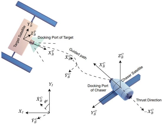
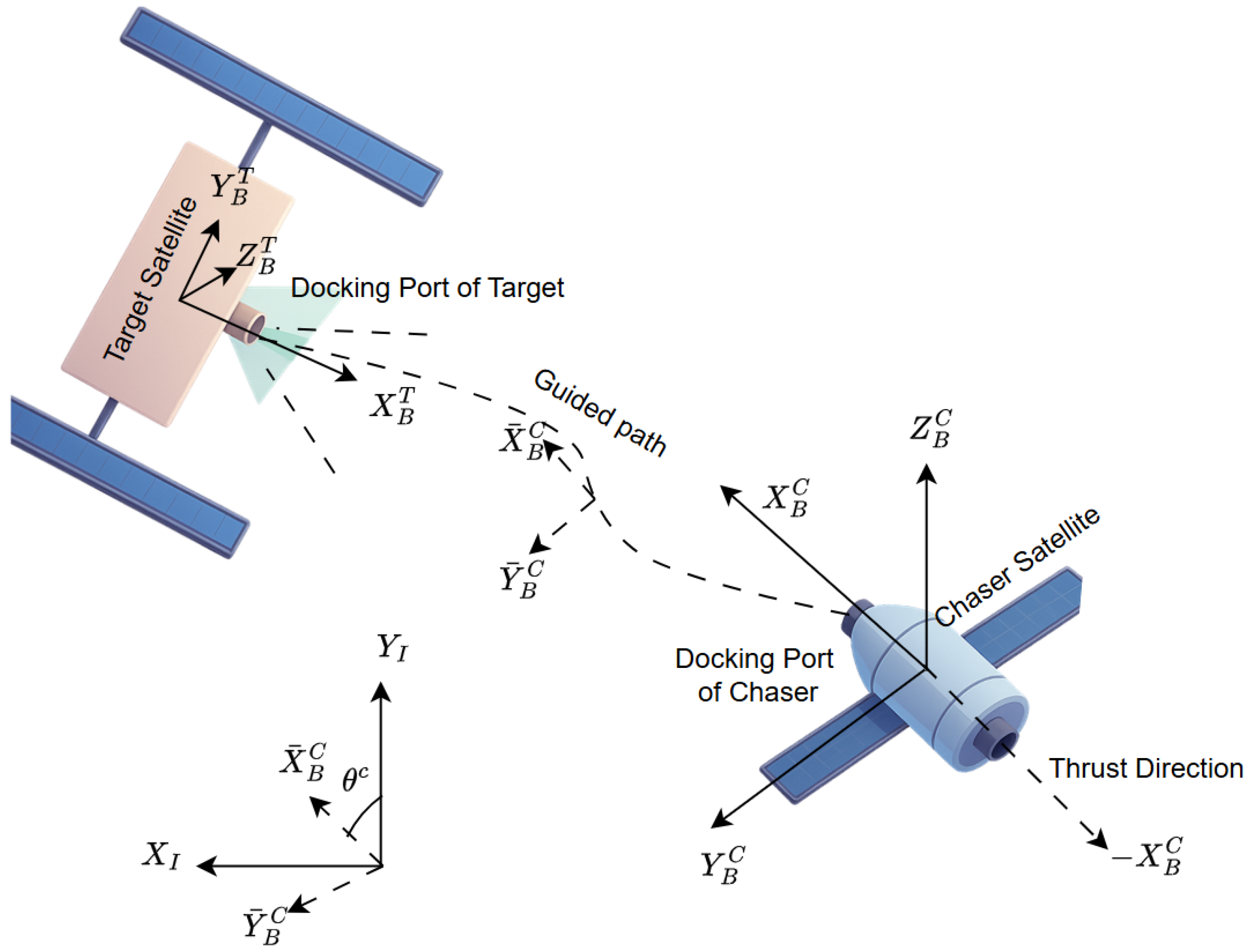
Safe and precise docking not only imposes the requirement for high terminal accuracy in terms of the relative position and velocity of the spacecraft, but also its terminal orientation relative to the docking port, making attitude regulation essential for accurate alignment of the docking interfaces. Typically, the actuation system of a spacecraft consists of dedicated thrusters for translational and rotational motion. Translational maneuvers are achieved using multiple small thrusters arranged to allow independent control of forces along the body-fixed axes. The direction of translational acceleration is therefore coupled with spacecraft orientation, but this configuration enables precise and smooth terminal maneuvers. This setup is consistent with the experimental floating platform used in this work and with typical on-orbit servicing vehicles employing cold-gas or low-thrust reaction control systems. A representative schematic is shown in Figure 1, where the thrust-based propulsion system for translational motion is attached to the chaser spacecraft , which is supposed to perform the docking operation to get attached to the target satellite . The body frame of reference for the chaser satellite is denoted by , where the thrust direction is indicated along the negative axis and the docking port of the chaser satellite is attached along the positive direction. Similarly, the body frame of reference for the target satellite is indicated by , where the docking port for the target satellite is placed along .
Figure 1.
Schematic representation of the space docking scenario, highlighting the importance of spacecraft orientation and its coupling with translational thruster directions.
Precise docking requires not only terminal constraints on relative position and velocity, but also strict regulation of relative orientation to ensure geometric alignment of the docking interfaces. Angular misalignment at contact can generate undesired lateral forces, contact torques, and residual rotational kinetic energy, potentially compromising capturability. Therefore, explicit attitude-constrained guidance is essential to guarantee smooth mechanical coupling during the terminal phase.
Additionally, from the control perspective, constraining acceleration at contact ensures reduced residual dynamics, minimizing the risk of undesired relative motion or instability due to nonzero residual kinetic energy associated with the relative translational dynamics. Residual rotational kinetic energy may also induce contact torques at the docking interface, further motivating the need for coordinated terminal motion constraints. Moreover, the terminal acceleration governs the force transmitted at contact; hence, leaving it as an open parameter might cause relatively high terminal acceleration, which can result in excessive impact forces that exceed the structural tolerances of the docking mechanisms. During the terminal phase, the transition from two-body to rigid-body dynamics necessitates acceleration continuity to prevent excitation of structural modes and ensure smooth mechanical coupling. Moreover, by coordinating the terminal orientation with a directed and bounded terminal body acceleration, the guidance law can ensure that the contact force is predominantly aligned along the docking axis, thereby minimizing undesired transverse loads and improving mechanical coupling during capture. These considerations collectively motivate the inclusion of terminal acceleration constraints as a necessary condition for the safe, precise, and dynamically consistent execution of autonomous docking operations, which have not been given due importance in the literature.
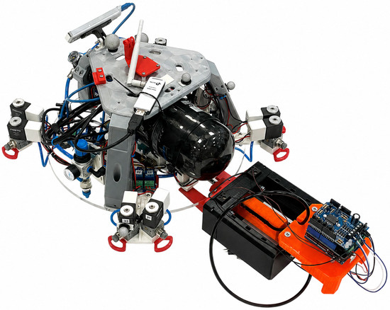
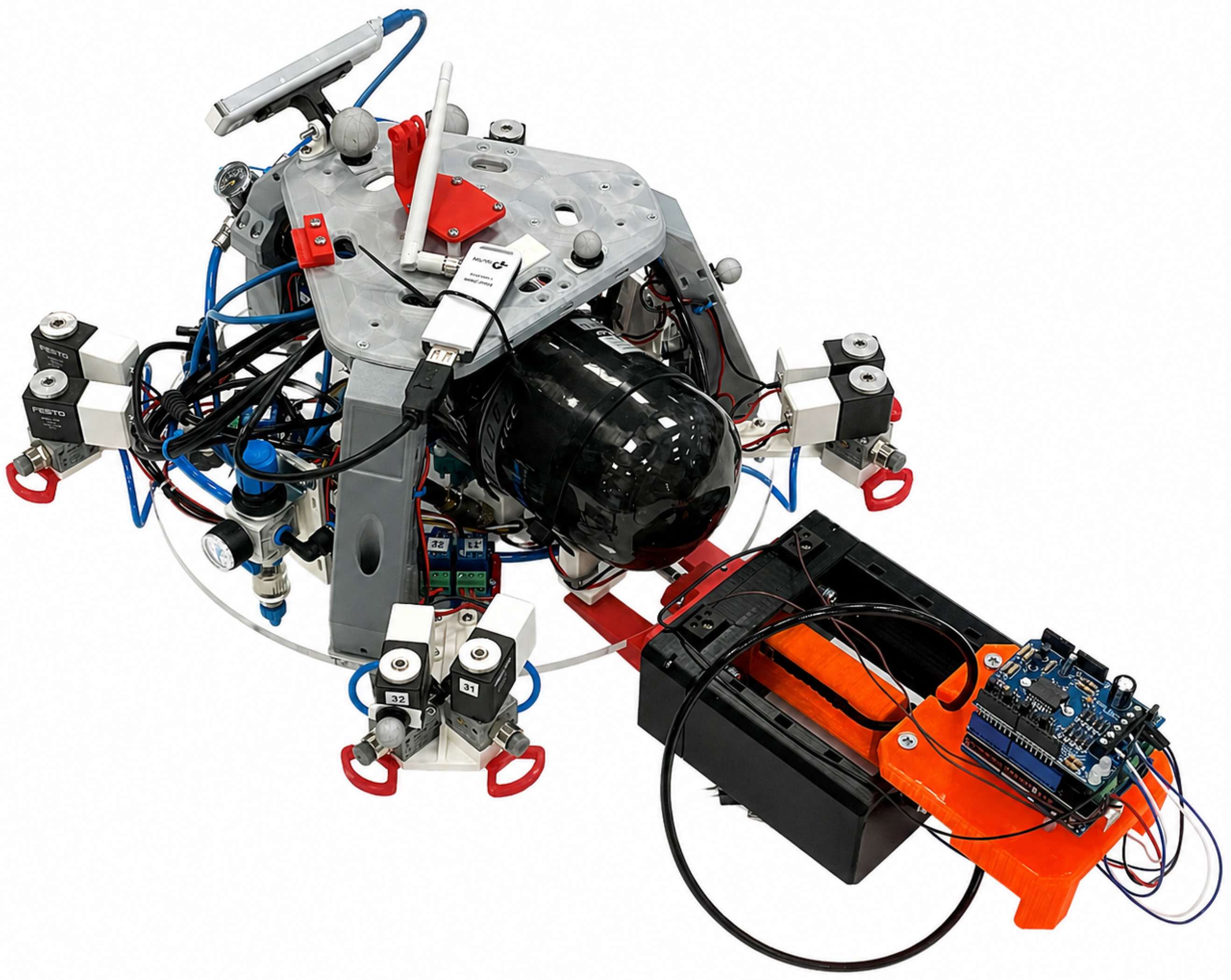
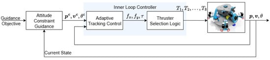
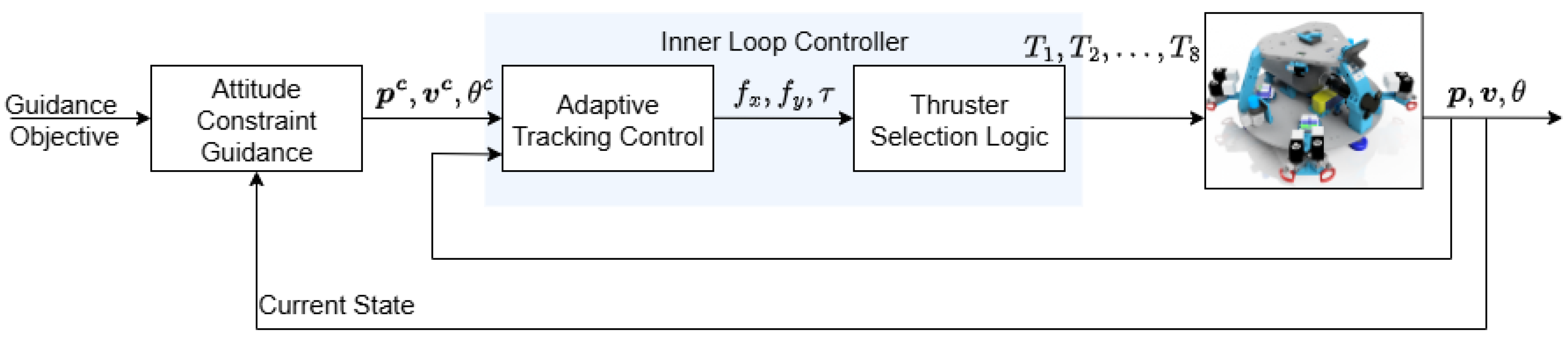
Figure 2 shows the experimental floating satellite platform integrated with an electromagnetically actuated docking port. The setup emulates a planar chaser–target docking scenario in a microgravity-like environment using an air-bearing platform. The floating body, representing the chaser satellite, is capable of translation and rotation on a frictionless surface, allowing for realistic motion dynamics. The electromagnetically actuated docking port enables controlled capture and release operations. Its magnetic attraction force is small compared to the nominal thrust and inertial forces during the terminal phase and, therefore, does not significantly affect the guidance or tracking performance prior to contact. This mechanism facilitates experimental demonstration of the proposed minimum-jerk guidance and adaptive tracking control algorithms on a floating satellite platform. The block diagram for the proposed minimum-jerk guidance (attitude-constrained guidance) and adaptive tracking control algorithm is shown in Figure 3.
Figure 2.
Experimental floating satellite platform connected with the electromagnetically actuated docking port.
Figure 3.
Schematic representation of the GNC architecture for the floating satellite platform.
3. Explicit Attitude Constrained Guidance
In autonomous docking missions, precise and stable control near the terminal phase requires more than just guiding the spacecraft to desired position and velocity targets. Guidance strategies traditionally focus on controlling acceleration directly as the system input [35]. However, such approaches are often limited to guaranteeing smooth transitions in acceleration profiles, a critical requirement for achieving safe and accurate docking maneuvers. To address this limitation, the minimum jerk guidance formulation redefines the problem by modeling the acceleration vector as a dynamic state variable and introducing jerk as the control input. This higher-order formulation allows both the initial and terminal accelerations to be imposed as hard boundary constraints, which is difficult if acceleration is treated purely as a control variable. Such constraints are essential for ensuring smooth transitions between sequential phases of the docking operation and maintaining continuity in thrust commands.
By minimizing jerk through a quadratic cost function, the formulation enables a closed-form optimal control solution. This yields not only an optimal jerk trajectory but also a smooth, time-varying acceleration profile that can serve as a real-time guidance command. This smoothness is particularly important for handling actuator limitations, reducing terminal control effort. The overview of the mathematical details underlying this formulation is presented in the following sections.
3.1. Closed-Form Optimal Guidance
The explicit guidance formulation is presented as the following optimal control problem. The objective of the minimum jerk guidance [36] is to minimize the integral of the norm squared jerk over the remaining time-to-go, defined as , thereby reducing abrupt changes in acceleration. Mathematically, this can be expressed as follows:
where is the initial remaining time-to-go at the start of the maneuver, and that decreases with the real-time. The system dynamics, in the domain, are represented as follows:
where, denote the commanded position, velocity, acceleration, and jerk vectors of the satellite, respectively, expressed in the inertial reference frame. Boundary conditions are imposed on position, velocity, and acceleration at both the initial and terminal times
Following the indirect approach for solving the optimal control problem, the Hamiltonian is defined as follows:
where, denote the intermediate costate variables. Following the derivation presented in [36], Pontryagin’s minimum principle yields the closed-form optimal jerk expression presented as follows:
where
From the above expressions one can easily verify that, at the final time the following holds
Following the derivation presented in [34], the explicit integration of the system dynamics while substituting the closed from jerk expression leads to
The associated coefficients are given by
Hence, as , , and ensuring the terminal position, velocity and acceleration requirements are satisfied as imposed by the guidance design. This guarantees a smooth stop at the docking point.
Even though the term appears in the denominators in the representation of the optimal jerk command in (9), the resulting expression for commanded states obtained from the closed-form solution in Equations (13)–(18), does not contain any denominator in . The only denominators that remain in the closed-form guidance solution appear in the coefficient expressions (Equations (16)–(18)) in terms of . Note that represents the initially computed remaining time-to-go at the start of the maneuver and is, therefore, a strictly positive quantity. In the closed-loop implementation, when is updated at each time step, to avoid singularities in numerical implementation near , a small threshold is used in practice, replacing with in the denominators.
The closed-form expressions in Equations (13)–(18) constitute the explicit guidance trajectories for position, velocity, and acceleration. By construction, these solutions satisfy the imposed boundary conditions in Equations (5)–(7), ensuring that and as . These trajectories serve as the reference inputs for the adaptive tracking controller described in Section 4.
3.2. Commanded Angular Displacement
A similar procedure is applied to compute the commanded angular displacement , with identical boundary conditions on initial and final angular position, velocity, and acceleration. The methodology yields a fifth-order polynomial for analogous to the translational states, ensuring smooth terminal attitude alignment. The commanded angular displacement of the floating platform is determined using a minimum-jerk trajectory approach analogous to the translational formulation. Let denote the desired orientation vector of the platform in roll, pitch, and yaw. The boundary conditions are given by the initial orientation , the final orientation , and zero initial and final angular velocities and accelerations
The minimum-jerk trajectory is then expressed as follows:
Angular velocities and accelerations are obtained by time differentiation
Although the methodology mirrors that of the translational minimum-jerk trajectory, the main difference lies in the kinematic mapping between angular displacement and body-frame angular velocity, which accounts for the rotational dynamics of the platform. This ensures smooth rotational maneuvers and precise alignment of the chaser platform with the docking port.
4. Adaptive Tracking Control
The guidance formulation presented in Section 3 is derived under the assumption that the spacecraft operates under nominal conditions, without accounting for the influence of external disturbances. However, in practice, the chaser spacecraft is subjected to various uncertainties, including time-varying mass properties, unmodeled actuator-induced effects arising from shifts in the center of gravity, and bounded on–off thruster actuation (i.e., thrusters operate with a fixed impulse per firing and cannot modulate force continuously).
This section presents the control design methodology based on an error-dependent transformation that explicitly incorporates performance constraints. To begin, consider the planar floating spacecraft model described by the Euler–Lagrange (EL) equation
where denotes the generalized coordinate vector, is the positive definite mass–inertia matrix, represents the lumped external disturbance, and the control input vector is defined as , where and denote the control forces along the body-fixed x- and y-axes, respectively, and represents the control torque about the body z-axis. These control efforts are then mapped to the corresponding thruster commands using the thruster selection logic described in detail in [37].
Following [38], to formulate a control law that ensures constraint-aware performance, we define an auxiliary tracking error variable as follows:
where is the tracking error, is the desired (commanded) state, is a diagonal, positive definite gain matrix, and is the reciprocal scaling matrix defined as follows:
where denotes the allowable state error bounds.
Multiplying both sides of the time derivative of (24) by yields
where . Substituting and using the system dynamics (23), we obtain
where
represents the combined system uncertainty. Its upper bound can be expressed as follows:
or more compactly, using EL system properties
where
Remark 1
(State-Dependent Uncertainties). The overall uncertainty depends explicitly on the system states through and , and cannot be assumed to be bounded by a constant a priori. This justifies the need for adaptive estimation of the coefficients.
The adaptive control law is then formulated as follows:
where is a positive definite gain matrix, and , , are adaptive estimates of the unknown coefficients, for .
The adaptation laws are defined as follows:
where are user-defined gains that saturate the values of the adaptive gains and . By virtue of the adaptive law, defined in (33), the adaptive gains compensate for the overall uncertainties defined in (30).
The proposed controller in (32), together with the adaptive laws in (33), ensures the stability of the closed-loop system. This adaptive barrier-Lyapunov-based controller ensures that the closed-loop system is Uniformly Ultimately Bounded (UUB), while guaranteeing that the tracking error remains strictly within the prescribed bound . The use of adaptive estimates allows the controller to compensate for the state-dependent uncertainties in real-time, including the effect of bounded on–off thrusters.
5. Experimental Results
5.1. Experimental Setup
The proposed guidance and control framework is experimentally demonstrated using a planar floating satellite platform, referred to as the Slider [39]. The platform hovers over a smooth, air-bearing surface, effectively emulating a near-zero-gravity environment in the horizontal plane by minimizing frictional effects. The Slider utilizes an array of air bearings that continuously supply pressurized air through precision nozzles, forming a thin air cushion beneath the base plate that allows unconstrained motion in both translation and rotation.
The platform is actuated by eight miniature cold-gas thrusters strategically positioned to generate control forces along the body-fixed X and Y axes, and control torques about the Z axis [39]. These thrusters are operated in an on–off mode through relay circuits, which are commanded by a microcontroller (Arduino Uno (Manufacturer: Arduino S.r.l., Sourced: RS-Components, Gothenburg, Västra Götaland County, Sweden)) interfaced with an onboard computer (LattePanda 3 Delta (Manufacturer: DFRobot, Sourced: Mouser Electronics Nordic AB, Malmö, Sweden)). Due to the on–off mode, each thruster can only provide discrete impulses, which limits the minimum control effort and may introduce small oscillations in velocity and acceleration profiles. The onboard computer executes the proposed guidance and control algorithms in real time and communicates the corresponding thruster commands via a serial interface.
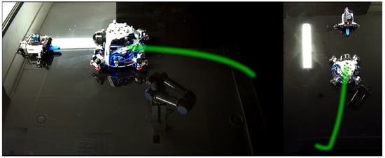
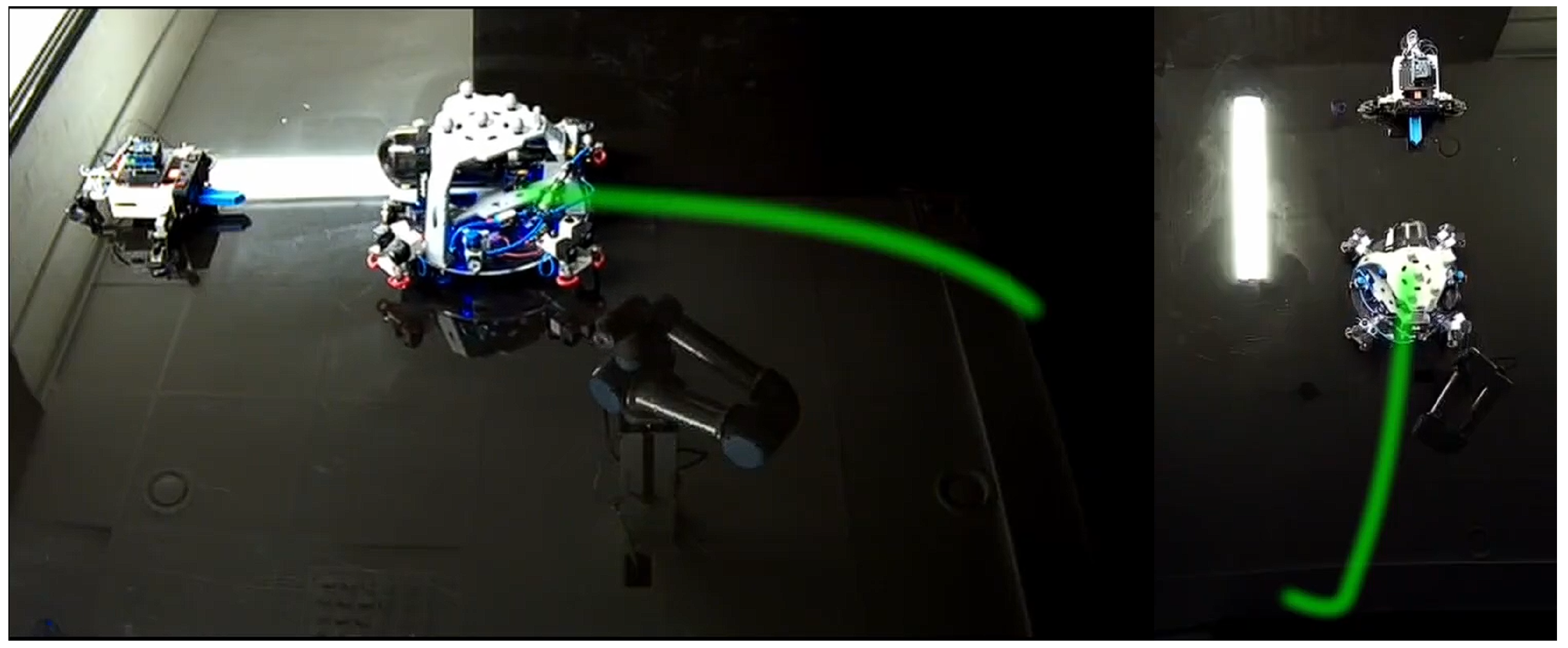
For precise state estimation, the experimental setup employs a Vicon motion-capture system that tracks the position and orientation of the Slider at a high sampling rate. The use of the motion capture system in the present experiments is dictated by the limitations of the current experimental platform, which does not include onboard relative navigation sensors. The Vicon motion capture system provides millimeter-level position accuracy and tenths-of-degree-level attitude accuracy within the calibrated workspace. Such performance relies on proper multi-camera geometric calibration and appropriate marker placement to ensure consistent visibility and tracking fidelity. The Vicon data are transmitted to the onboard processor through a wireless network, enabling closed-loop feedback control. The scope of this work is focused on the development and experimental demonstration of the proposed guidance and control framework, and, therefore, the controller is designed under the standard assumption that accurate state feedback is available. The motion capture system is thus used to provide high-fidelity state measurements for controller evaluation. The overall experimental testbed, consisting of the floating spacecraft platform and an electromagnetically actuated docking station, is shown in Figure 4. This setup provides a realistic and controlled environment to evaluate the proposed guidance and control algorithms for autonomous docking operations under planar microgravity-like conditions.
Figure 4.
A snapshot from the experiment demonstrating the floating platform moving toward the docking port, captured from two different camera viewing angles. The green line indicates its trajectory.
5.2. Results and Analysis
The initial and final desired states are defined as follows, with the final time-to-go specified as s.
The initial states are measured directly from the experimental platform at the start of the maneuver, while the final desired states are defined according to the docking port configuration.
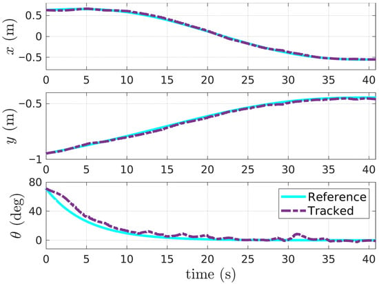
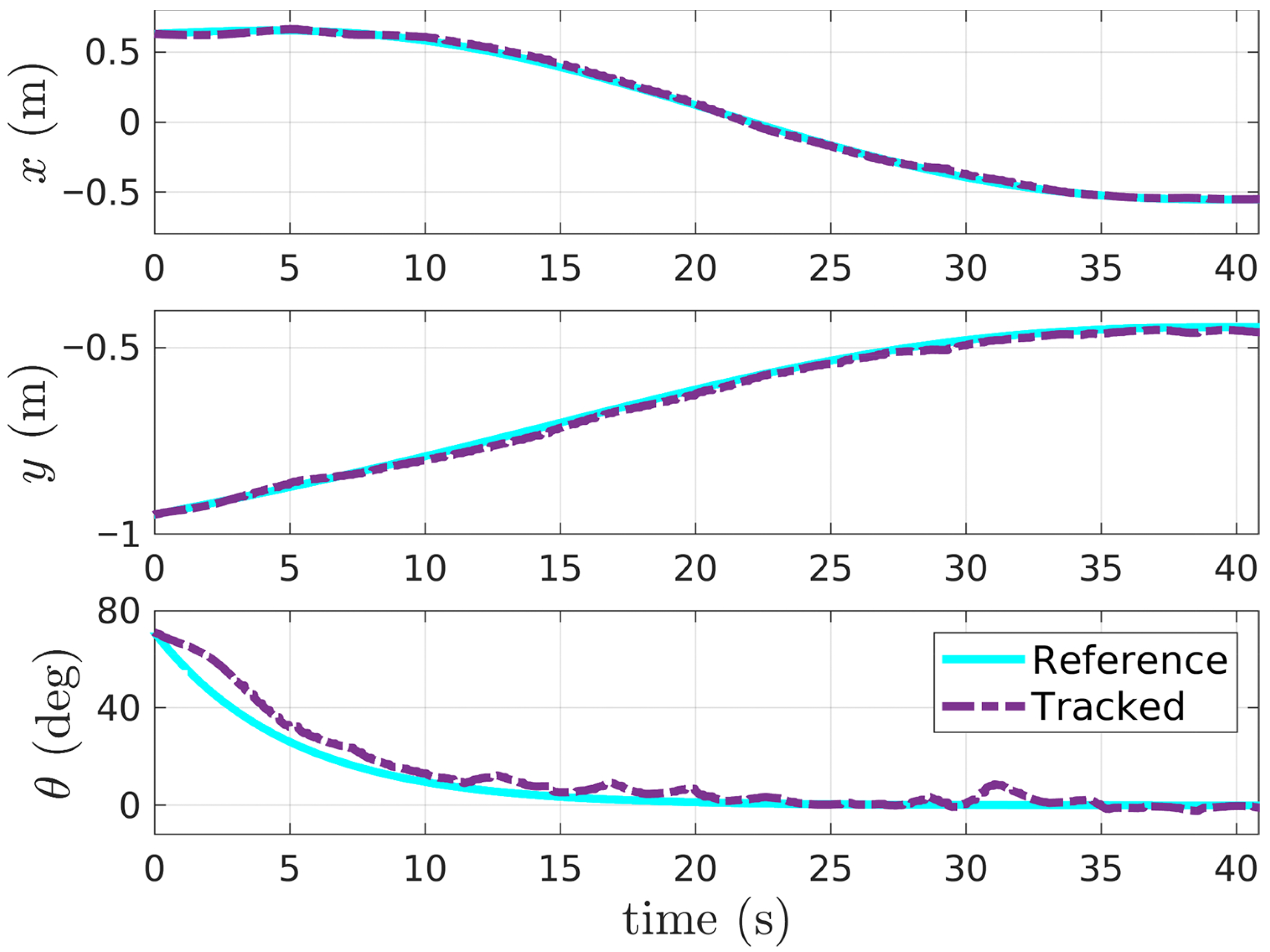
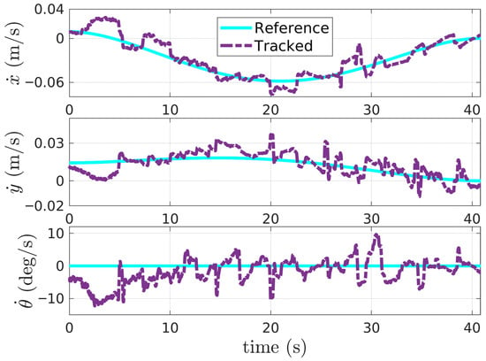
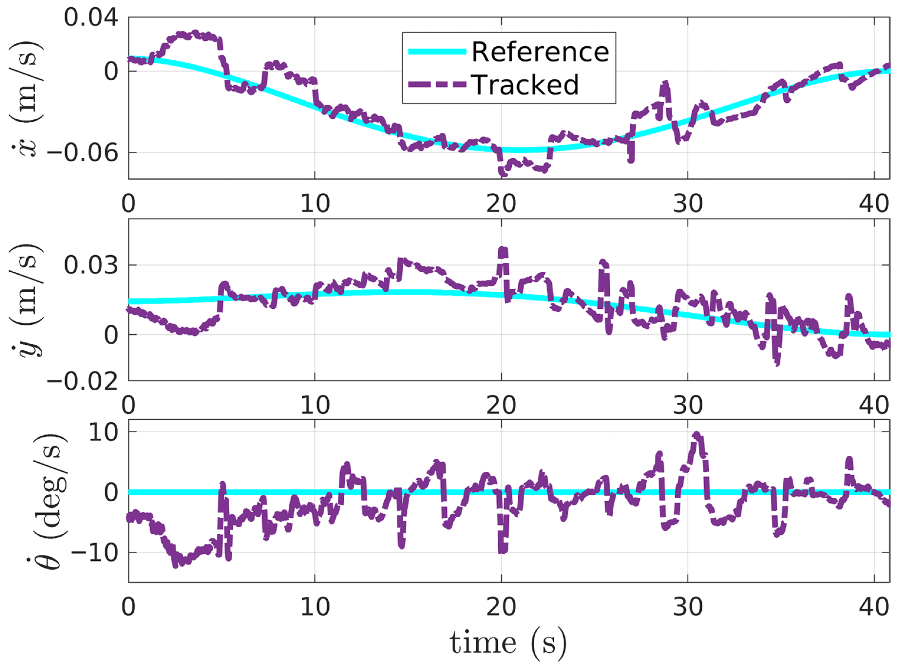
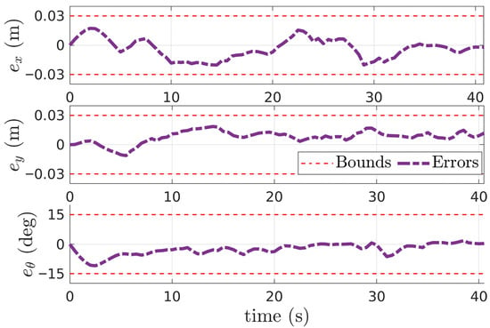
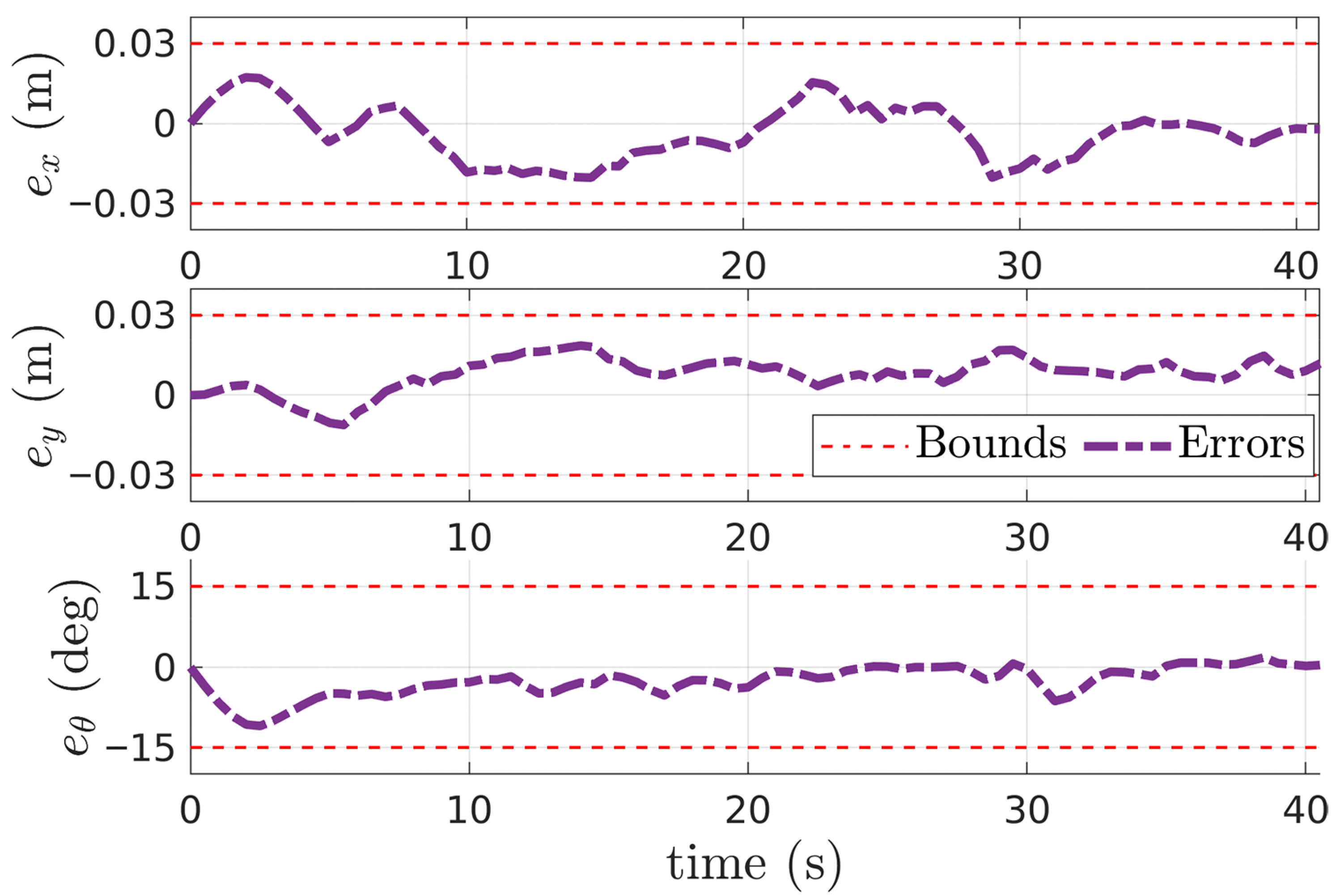
Figure 5, Figure 6, Figure 7, Figure 8 and Figure 9 illustrate the performance of the proposed controller in tracking the commanded trajectory. The experiment begins with the floating platform initialized at m, m, and an initial orientation of . The guidance module is then activated to generate smooth reference trajectories for position and velocity, as shown in Figure 5 and Figure 6. These reference trajectories are discretized and provided to the controller at each control step. The control parameters used in the experiment are: m and degrees, , and .
Figure 5.
Position with time.
Figure 6.
Velocity with time.
Figure 7.
Position error with time.
Figure 8.
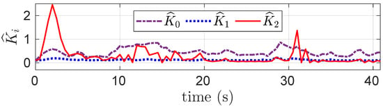
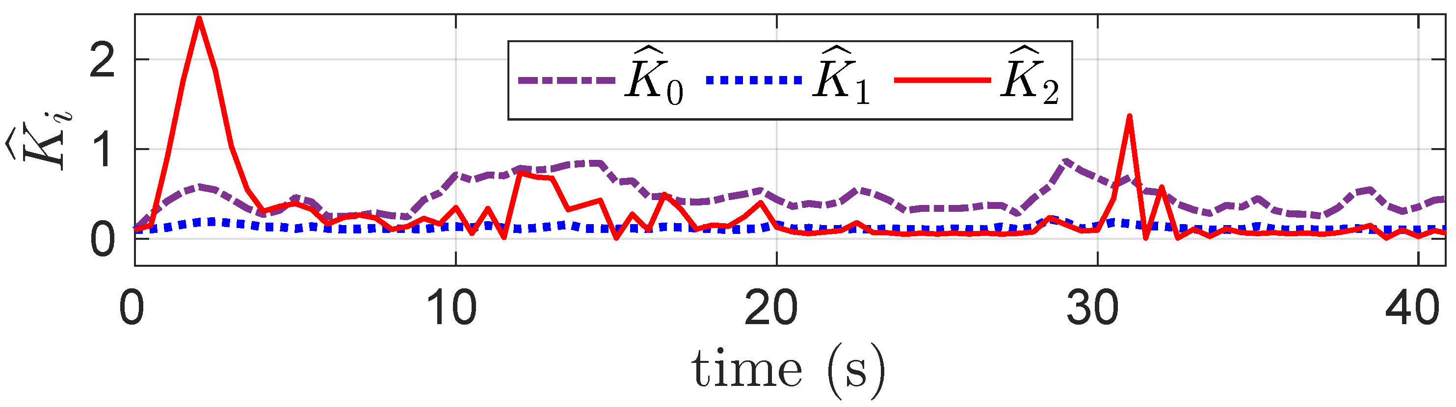
Adaptive gains with time.
Figure 9.
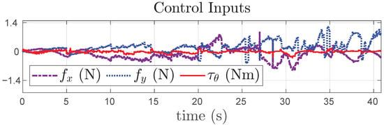
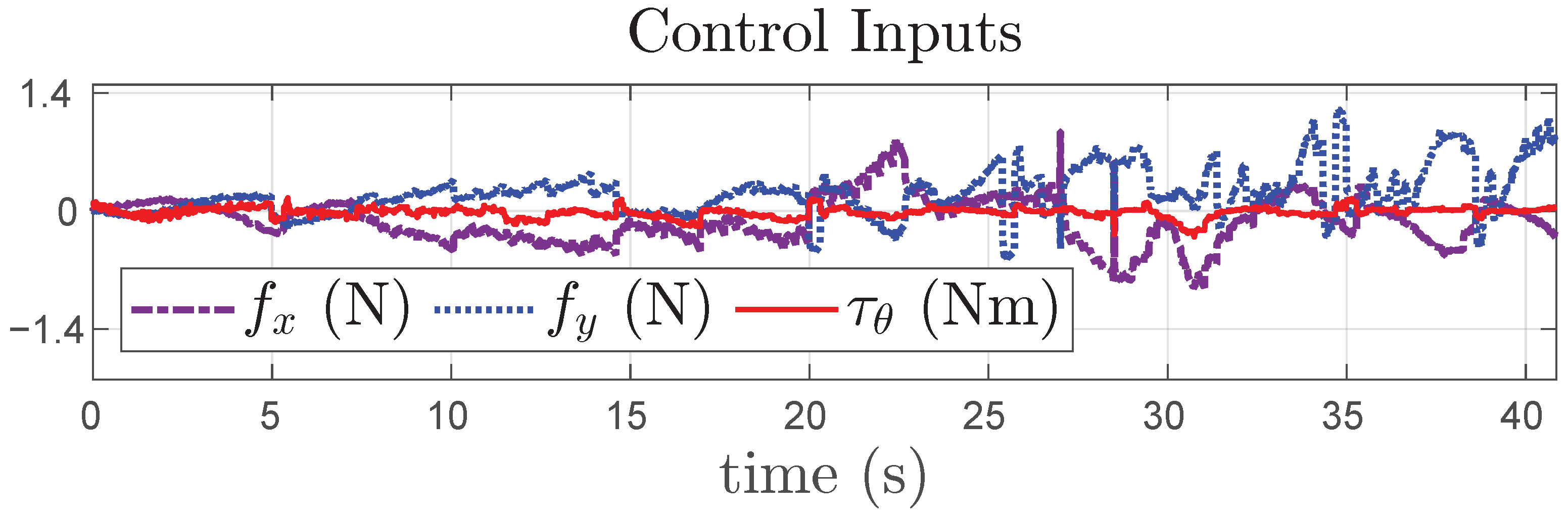
Variation of force and torque control with time.
Despite the presence of external disturbances, modeling uncertainties, and discrete thruster actuation, the controller effectively enforces the imposed state constraints, ensuring that the platform remains within a closely bounded trajectory with minimal error in all DoF, as noted in Figure 7. As observed in Figure 6, the velocity profile exhibits mild oscillations with magnitudes of m s−1 and deg s−1 (approx. rad s−1) in linear and angular velocities, respectively; these are attributed to a combination of the minimum impulse bit of the on–off thrusters and the transient adaptation of the estimated coefficients in the adaptive control law (Figure 8). The coefficients converge online to compensate for state-dependent uncertainties.
While the magnitudes of errors shown in Figure 7 are well within the bounds at all times, at around 30 s, minor deviations occur in all dimensions due to external disturbances, which cause the adaptive gains to increase a little to produce a higher magnitude of control input, as shown in Figure 9. Note that such external disturbances may appear due to the minor non-smooth regions on the glass surface, where the platform moves. Similarly, after 35 s, the platform comes in contact with the docking socket, which causes minor oscillations in the velocity. While these oscillations do not impact the adaptive gains much, they produce a larger magnitude of control to compensate for the additional disturbances caused by the docking station. Under ideal conditions, the residual control input is expected to reduce to zero. However, in real experiments, in the presence of unknown external disturbances, a nonzero control action is observed to compensate for these effects and maintain alignment after docking.
Additionally, we would like to highlight here that, although the motion capture system inherently introduces some measurement noise, systematic artificial noise injection was not considered in this study, as the primary objective is to experimentally assess the guidance and adaptive tracking performance. A comprehensive evaluation of robustness to degraded navigation accuracy remains within the scope of future work. The corresponding experimental demonstration video further highlights the smooth and reliable performance of the proposed approach (https://youtu.be/hp72GZWPXw0 (accessed on 19 April 2026)).
It should be noted that while the free-floating platform provides a valuable laboratory-scale environment for testing rendezvous and docking strategies, its dynamics differ fundamentally from those in orbital conditions. As such, the experimental results cannot be considered a one-to-one validation of in-orbit performance. Nevertheless, the platform allows controlled evaluation of controller behavior, interaction dynamics, and system response under near-realistic conditions, making it an essential intermediate step for hardware-in-the-loop emulation before in-orbit implementation.
6. Conclusions
This article presented an adaptive, attitude-constrained guidance and control framework for safe and autonomous spacecraft docking, experimentally demonstrated using a planar floating satellite platform. The proposed approach integrates a minimum-jerk explicit guidance law that guarantees smooth trajectories satisfying terminal constraints on position, velocity, and acceleration, while maintaining computational tractability for real-time implementation. To ensure robustness against modeling uncertainties, actuator nonlinearities, and external disturbances, a barrier-Lyapunov-based adaptive controller was developed, enabling state constraint enforcement and guaranteeing bounded tracking errors within predefined limits. The experimental evaluation demonstrated that the proposed scheme achieves precise docking with a high terminal accuracy of approximately cm in relative position, and in relative orientation. The tracking errors remained within the prescribed bounds ( m, ) throughout the maneuver. The results confirm the practical applicability and robustness of the proposed framework, highlighting its potential for future on-orbit servicing and autonomous proximity operations.
Author Contributions
V.N.S.: Writing—review & editing, Writing—original draft, Visualization, Experimental demonstration, Methodology, Investigation, Formal analysis, Data curation, Conceptualization. S.S.: Writing—review & editing, Methodology. A.B.: Writing—review & editing, Supervision, Investigation, and Conceptualization. J.H.: Writing—review & editing, Experimental evaluation. G.N.: Review & editing, Supervision, Investigation, and Conceptualization. All authors have read and agreed to the published version of the manuscript.
Funding
This work was partially supported by Kempestiftelserna (The Kempe Foundations), and partially by the Wallenberg AI, Autonomous Systems and Software Program (WASP) funded by the Knut and Alice Wallenberg Foundation.
Data Availability Statement
The original contributions presented in the study are included in the article, further inquiries can be directed to the corresponding author.
Acknowledgments
The authors gratefully acknowledge the financial support of Kempestiftelserna for partially funding the establishment of the Space Robotics Laboratory at Luleå University of Technology, which enabled this research.
Conflicts of Interest
The authors declare no conflicts of interest. The funders had no role in the design of the study; in the collection, analyses, or interpretation of data; in the writing of the manuscript; or in the decision to publish the results.
References
- Petersen, C.D.; Phillips, S.; Hobbs, K.L.; Lang, K. Challenge problem: Assured satellite proximity operations. In Proceedings of the 31st AAS/AIAA Space Flight Mechanics Meeting; Univelt, Inc.: Escondido, CA, USA, 2021; Volume 176. [Google Scholar]
- Li, W.J.; Cheng, D.Y.; Liu, X.G.; Wang, Y.B.; Shi, W.H.; Tang, Z.X.; Gao, F.; Zeng, F.M.; Chai, H.Y.; Luo, W.B.; et al. On-orbit service (OOS) of spacecraft: A review of engineering developments. Prog. Aerosp. Sci. 2019, 108, 32–120. [Google Scholar] [CrossRef] [Scilit]
- Svotina, V. Space debris removal–review of technologies and techniques. Rigid coupling between space debris and service spacecraft. J. Space Saf. Eng. 2024, 11, 252–267. [Google Scholar] [CrossRef] [Scilit]
- Malyh, D.; Vaulin, S.; Fedorov, V.; Peshkov, R.; Shalashov, M. A brief review on in-orbit refueling projects and critical techniques. Aerosp. Syst. 2022, 5, 185–196. [Google Scholar] [CrossRef] [Scilit]
- Wang, Z.; Wang, P.; Duan, J.; Tian, W. Review of On-Orbit Assembly Technology with Space Robots. Aerospace 2025, 12, 375. [Google Scholar] [CrossRef] [Scilit]
- Newman, C.J.; Williamson, M. Space sustainability: Reframing the debate. Space Policy 2018, 46, 30–37. [Google Scholar] [CrossRef] [Scilit]
- Wertz, J.R.; Bell, R. Autonomous rendezvous and docking technologies: Status and prospects. Space Syst. Technol. Oper. 2003, 5088, 20–30. [Google Scholar]
- Machula, M.; Sandhoo, G. Rendezvous and docking for space exploration. In Proceedings of the 1st Space Exploration Conference: Continuing the Voyage of Discovery, Orlando, FL, USA, 30 January–1 February 2005; p. 2716. [Google Scholar]
- Kluever, C.A. Feedback control for spacecraft rendezvous and docking. J. Guid. Control. Dyn. 1999, 22, 609–611. [Google Scholar] [CrossRef] [Scilit]
- Balakrishnan, S.; Gurfil, P. Feedback control for directional rendezvous using constant-magnitude low thrust. J. Guid. Control. Dyn. 2024, 47, 2497–2511. [Google Scholar] [CrossRef] [Scilit]
- Capello, E.; Punta, E.; Dabbene, F.; Guglieri, G.; Tempo, R. Sliding-mode control strategies for rendezvous and docking maneuvers. J. Guid. Control. Dyn. 2017, 40, 1481–1487. [Google Scholar] [CrossRef] [Scilit]
- Guglieri, G.; Maroglio, F.; Pellegrino, P.; Torre, L. Design and development of guidance navigation and control algorithms for spacecraft rendezvous and docking experimentation. Acta Astronaut. 2014, 94, 395–408. [Google Scholar] [CrossRef] [Scilit]
- Andrade, C.; Ramirez-Mendoza, R.; Giacoman-Zarzar, M.; Morales, R.; Fejzic, A.; Saenz-Otero, A.; Miller, D.W. Robust control applied towards rendezvous and docking. In Proceedings of the 2009 European Control Conference (ECC); IEEE: Piscataway, NJ, USA, 2009; pp. 1854–1859. [Google Scholar]
- Weiss, A.; Baldwin, M.; Erwin, R.S.; Kolmanovsky, I. Model predictive control for spacecraft rendezvous and docking: Strategies for handling constraints and case studies. IEEE Trans. Control Syst. Technol. 2015, 23, 1638–1647. [Google Scholar] [CrossRef] [Scilit]
- Yang, Y. Coupled orbital and attitude control in spacecraft rendezvous and soft docking. Proc. Inst. Mech. Eng. Part G J. Aerosp. Eng. 2019, 233, 3109–3119. [Google Scholar] [CrossRef] [Scilit]
- Lee, D.; Pernicka, H. Optimal control for proximity operations and docking. Int. J. Aeronaut. Space Sci. 2010, 11, 206–220. [Google Scholar] [CrossRef] [Scilit]
- Di Cairano, S.; Park, H.; Kolmanovsky, I. Model predictive control approach for guidance of spacecraft rendezvous and proximity maneuvering. Int. J. Robust Nonlinear Control 2012, 22, 1398–1427. [Google Scholar] [CrossRef] [Scilit]
- Bashnick, C.; Ulrich, S. Fast model predictive control for spacecraft rendezvous and docking with obstacle avoidance. J. Guid. Control. Dyn. 2023, 46, 998–1007. [Google Scholar] [CrossRef] [Scilit]
- Leomanni, M.; Rogers, E.; Gabriel, S.B. Explicit model predictive control approach for low-thrust spacecraft proximity operations. J. Guid. Control. Dyn. 2014, 37, 1780–1790. [Google Scholar] [CrossRef] [Scilit]
- Fear, A.; Lightsey, E.G. Autonomous rendezvous and docking implementation for small satellites using model predictive control. J. Guid. Control. Dyn. 2024, 47, 539–547. [Google Scholar] [CrossRef] [Scilit]
- Singla, P.; Subbarao, K.; Junkins, J.L. Adaptive output feedback control for spacecraft rendezvous and docking under measurement uncertainty. J. Guid. Control. Dyn. 2006, 29, 892–902. [Google Scholar] [CrossRef] [Scilit]
- Jewison, C.M. Guidance and Control for Multi-Stage Rendezvous and Docking Operations in the Presence of Uncertainty. Ph.D. Thesis, Massachusetts Institute of Technology, Cambridge, MA, USA, 2017. [Google Scholar]
- Breeden, J.; Panagou, D. Guaranteed safe spacecraft docking with control barrier functions. IEEE Control Syst. Lett. 2021, 6, 2000–2005. [Google Scholar] [CrossRef] [Scilit]
- Saradagi, A.; Sankaranarayanan, V.N.; Banerjee, A.; Satpute, S.; Nikolakopoulos, G. Switched control barrier functions-based safe docking control strategy for a planar floating platform. Control Eng. Pract. 2025, 158, 106274. [Google Scholar]
- Dong, H.; Hu, Q.; Akella, M.R. Safety control for spacecraft autonomous rendezvous and docking under motion constraints. J. Guid. Control. Dyn. 2017, 40, 1680–1692. [Google Scholar] [CrossRef] [Scilit]
- Li, Q.; Zhang, B.; Yuan, J.; Wang, H. Potential function based robust safety control for spacecraft rendezvous and proximity operations under path constraint. Adv. Space Res. 2018, 62, 2586–2598. [Google Scholar] [CrossRef] [Scilit]
- Salehi, I.; Rotithor, G.; Trombetta, D.; Dani, A.P. Safe tracking control of an uncertain euler-lagrange system with full-state constraints using barrier functions. In Proceedings of the 2020 59th IEEE Conference on Decision and Control (CDC); IEEE: Piscataway, NJ, USA, 2020; pp. 3310–3315. [Google Scholar]
- Guo, Y.; Zhang, D.; Li, A.J.; Song, S.; Wang, C.Q.; Liu, Z. Finite-time control for autonomous rendezvous and docking under safe constraint. Aerosp. Sci. Technol. 2021, 109, 106380. [Google Scholar] [CrossRef] [Scilit]
- Wang, S.; Wen, S. Safe control against uncertainty: A comprehensive review of control barrier function strategies. IEEE Syst. Man Cybern. Mag. 2025, 11, 34–47. [Google Scholar] [CrossRef] [Scilit]
- Governale, G.; Pastore, A.; Clavolini, M.; Li Vigni, M.; Bellinazzi, C.; Matonti, C.L.; Aliberti, S.; Apa, R.; Romano, M. Hardware-in-the-Loop Testing of Spacecraft Relative Dynamics and Tethered Satellite System on a Tip-Tilt Flat-Table Facility. Aerospace 2025, 12, 884. [Google Scholar] [CrossRef] [Scilit]
- Banerjee, A.; Tevetzidis, I.; Satpute, S.G.; Nikolakopoulos, G. Nonlinear Dynamic Inversion-Based Motion Planning of a Floating Satellite Platform. In Proceedings of the AIAA SCITECH 2025 Forum, Orlando, FL, USA, 6–10 January 2025; p. 1190. [Google Scholar]
- Saradagi, A.; Banerjee, A.; Satpute, S.; Nikolakopoulos, G. Safe Autonomous Docking Maneuvers for a Floating Platform based on Input Sharing Control Barrier Functions. In Proceedings of the 2022 IEEE 61st Conference on Decision and Control (CDC); IEEE: Piscataway, NJ, USA, 2022; pp. 3746–3753. [Google Scholar]
- Wang, Y.; Wang, X.; Liu, C.; Zhang, H.; Zhou, H.; Zhang, X.; Wang, H. State-constrained control strategy for safe navigation trajectory tracking of hovercraft based on improved barrier Lyapunov function. Ocean Eng. 2024, 303, 117791. [Google Scholar] [CrossRef] [Scilit]
- Padhi, R.; Banerjee, A.; Sai Kumar, P.; Parvathi, S. Attitude constrained robust explicit guidance for terminal phase of autonomous lunar soft-landing. J. Astronaut. Sci. 2024, 71, 20. [Google Scholar] [CrossRef] [Scilit]
- Zhang, W.; Chen, W.; Li, J.; Yu, W. Guidance algorithm for impact time, angle, and acceleration control under varying velocity condition. Aerosp. Sci. Technol. 2022, 123, 107462. [Google Scholar] [CrossRef] [Scilit]
- Banerjee, A.; Padhi, R. An optimal explicit guidance algorithm for terminal descent phase of lunar soft landing. In Proceedings of the AIAA Guidance, Navigation, and Control Conference, Grapevine, TX, USA, 9–13 January 2017; p. 1266. [Google Scholar]
- Banerjee, A.; Haluska, J.; Satpute, S.G.; Kominiak, D.; Nikolakopoulos, G. Slider: On the Design and Modeling of a 2D Floating Satellite Platform. arXiv 2021. [Google Scholar] [CrossRef] [Scilit]
- Sankaranarayanan, V.N.; Satpute, S.; Roy, S.; Nikolakopoulos, G. Adaptive Control of Euler-Lagrange Systems under Time-varying State Constraints without a Priori Bounded Uncertainty. IFAC-PapersOnLine 2023, 56, 3360–3365. [Google Scholar] [CrossRef] [Scilit]
- Banerjee, A.; Satpute, S.G.; Kanellakis, C.; Tevetzidis, I.; Haluska, J.; Bodin, P.; Nikolakopoulos, G. On the design, modeling and experimental verification of a floating satellite platform. IEEE Robot. Autom. Lett. 2022, 7, 1364–1371. [Google Scholar] [CrossRef] [Scilit]
Disclaimer/Publisher’s Note: The statements, opinions and data contained in all publications are solely those of the individual author(s) and contributor(s) and not of MDPI and/or the editor(s). MDPI and/or the editor(s) disclaim responsibility for any injury to people or property resulting from any ideas, methods, instructions or products referred to in the content. |
© 2026 by the authors. Licensee MDPI, Basel, Switzerland. This article is an open access article distributed under the terms and conditions of the Creative Commons Attribution (CC BY) license.