


Abstract
Unconventional aircraft configurations show significant potential to reduce aviation’s environmental footprint. Computerized conceptual design environments enable the design of unconventional aircraft concepts and the comparison of their performance and environmental impact against conventional Tube-And-Wing aircraft and other competing unconventional layouts. However, no environment has yet been specifically developed to support the Twin-Fuselage configuration. This paper addresses this gap by analyzing the advantages of the Twin-Fuselage configuration, identifying a potentially relevant design space, and compiling the existing conceptual-level design methods applicable to this layout. Building on these results, a roadmap for the conception of computerized conceptual design environments supporting Twin-Fuselage aircraft is presented. A structured environment architecture is proposed considering current trends and limitations of state-of-the-art environments supporting other unconventional configurations. The proposed modules for each discipline are also outlined. Finally, the main research gaps in Twin-Fuselage aircraft conceptual design are identified, highlighting and prioritizing the developments needed to enable a fully operational Twin-Fuselage-supporting computerized conceptual design environment.
1. Introduction
Aviation’s measurable contribution to human-caused global warming is currently estimated at around 4% [1], with this share expected to increase as air traffic continues to grow. Projections indicate that maintaining the present average annual traffic growth rate of approximately 4.4% would lead to a tripling of global aviation emissions by 2050 [2]. Such a scenario is incompatible with international climate objectives targeting net-zero global CO2 emissions by mid-century [3], and which are aligned with the sustainability goals established by international aviation organizations [4,5].
The introduction of Sustainable Aviation Fuels (SAF) offers significant mitigation potential, with gradual deployment supported by public policy measures. For example, the European Union has agreed to increase SAF uptake at its airports from 2% in 2025 to 20% by 2035 and 70% by 2050 [6]. Improvements in air traffic management and operational efficiency are also expected to contribute approximately 8% of the required emissions reductions [4]. Regarding aircraft technologies, revolutionary concepts, such as electric and hydrogen-powered aircraft, are promising. Even so, their Technology Readiness Levels (TRLs) remain low, and they would require major infrastructure changes. As a result, their expected entry into service is projected too close to 2050 [7] to achieve sufficient market penetration to deliver a major emissions benefit [4]. State-of-the-art technologies, such as advanced materials, boundary layer ingestion, hybrid laminar flow control, and open rotors, are also driven by sustainability concerns [2]. However, their application to conventional Tube-And-Wing (TAW) aircraft only yields incremental reductions in fuel consumption. Consequently, unconventional aircraft configurations are attracting increasing attention, as they show potential fuel efficiency benefits of up to 30% when compared to TAW aircraft [2].
Unconventional configurations pursue different strategies that aim to reduce fuel consumption and Direct Operating Costs (DOC). As an example, flying wings and Blended Wing Bodies (BWBs) aim to increase aerodynamic efficiency by locating the payload in a lifting body, while multi-bodies and Strut-Braced Wings (SBWs) aim to reduce induced drag by increasing the wing aspect ratio [8]. The main challenge with these solutions is that they entail substantial modifications with respect to the TAW configuration. This results in high research and development costs and industrial risk. Thus, it is paramount to justify their advantages from early on in the design process. The conceptual design phase is estimated to influence over 70% of an aircraft’s Life-Cycle Costs (LCC) [9]. Therefore, the development of conceptual design methodologies able to assess unconventional aircraft benefits reliably is crucial to justify the selection of these concepts for the preliminary design phase.
The growth in computational power has shifted conceptual design methodologies from low-fidelity analytical sizing procedures and statistical methods [8,10] to modular computerized design environments [11,12], which offer low- and medium-fidelity methods and combine different disciplines. The scarcity of historical data for unconventional configurations makes these environments even more suited to their conceptual design. However, computerized design environments conceived for TAW aircraft are incapable of producing unconventional concepts, as particular methods and whole modules have to be adapted depending on the target configuration.
In previous work, the authors conducted a review of existing environments supporting unconventional aircraft design [13]. It was observed that up to fourteen environments supported the design of tailless configurations, including, among others, flying wings and BWBs. Among these environments, CADLab [14], GENUS [15], RAMP [16], SUAVE [17] and the environment developed by Mavris et al. [18] focused solely on the conceptual design phase, while the remaining ones either focused on preliminary design or combined methodologies and objectives from both phases. On the contrary, other types of unconventional configurations were observed to be supported by significantly fewer alternatives, even though their potential improvements in terms of consumption and costs are comparable [2]. Externally braced wings, such as SBW and Truss-Braced Wings (TBWs), were supported by five environments: ADS [19], AGILE [20], FAST [21], LAMBDA [22] and SUAVE [23]; and closed-wing configurations, including box wings and joined wings, by three: AGILE [20], CEASIOM [24], and SUAVE [25].
Notably, multi-body configurations were not supported by any of the reviewed environments natively, despite some operational examples existing outside the transport category [26,27]. Ma et al. [28] have adapted SUAVE for the design of Twin-Fuselage (TF) aircraft, the best-suited design in the multi-body category for transport aircraft [8]. To do so, they added a wing weight estimation method, adapted from Udin and Anderson [29], and a parasite drag estimation method. Nevertheless, developing a conceptual design environment specifically conceived to support TF aircraft and to compare the results with the TAW configuration would allow developing each module considering the specific requirements of the TF configuration. This would lead to increased result reliability and confidence in the advantages of TF aircraft. Therefore, the present work aims to lay the groundwork for developing a computerized environment capable of supporting the conceptual design of TF aircraft.
The rest of this paper is structured as follows: Section 2 presents the methodological aspects that concern the most affected modules by each unconventional configuration, Section 3 outlines a potential design space of interest for TF aircraft and presents the existing conceptual level methods for TF aircraft design, Section 4 describes a roadmap for the creation of TF computerized conceptual design environments, and Section 5 provides concluding remarks.
2. Methodological Considerations for Each Unconventional Configuration
The present section introduces the required modifications to conventional methods applied to TAW aircraft conceptual design, depending on the target unconventional configuration. Unconventional configurations based on substantial changes to the body and/or lifting surfaces are considered. These configurations require modifications across different disciplinary modules. In contrast, aircraft that incorporate other types of innovation, such as new propulsion technologies, aerodynamic enhancements or structural improvements, generally keep the general arrangement unchanged and only affect individual modules.
The unconventional aircraft classification presented in Figure 1 is adopted to structure this discussion. This taxonomy, introduced by the authors in [13] and adapted from [8], categorizes unconventional aircraft into seven groups according to the degree to which each configuration alters the underlying disciplinary modules.
Figure 1.
Unconventional aircraft classification. (A) unconventional tails; (B) single body, planar lifting surfaces; (C) tailless configurations; (D) externally-braced wings; (E) closed wing configurations; (F) multi-body; (G) radical configurations.
The first step in establishing the degree of impact of each module for a given configuration is to identify which disciplinary modules are most affected by changes in the aircraft’s general arrangement. Most computerized design environments include the following modules, listed in decreasing order of frequency: aerodynamics, weight estimation, mission and performance, propulsion, geometric representation, optimization, structures, and stability and control [13].
Among these, the mission and performance module is not directly influenced by configuration changes, as it relies on the same input parameters regardless of the aircraft layout. Similarly, the propulsion module is primarily affected by innovations in the propulsion system, which are not taken into account in the aforementioned classification. In contrast, the geometric representation module must accommodate the addition of alternative bodies and lifting surfaces. However, this module is often handled by external software, and widely used tools, such as OpenVSP [18,30,31,32], CATIA [18,22,33] and Siemens NX [34,35], already support such capabilities. Finally, the optimization module may be indirectly influenced by changes in geometric parameterization. Nevertheless, it is considered beyond the scope of this discussion, as it mostly belongs to the preliminary and detailed design phases.
Consequently, the modules most relevant to this study are aerodynamics, weight estimation, structures, and stability and control. In the present study, the structures and weight estimation modules are assessed together, as the primary modifications to the weight estimation module arise from changes in structural weight. Other innovations which could affect the aircraft’s weight, such as the use of alternative power sources to kerosene, are not considered within the chosen definition for unconventional configuration.
To formalize the assessment of module impacts across configurations, a set of criteria-based matrices was developed. Each matrix defined explicit layout-based criteria capturing the main sources of deviation from the TAW configuration within each discipline. Thresholds were established to classify the level of modification as minor (zero or one criterion), moderate (two criteria) or major (three or more criteria). Group G was directly considered to require major modifications across all modules, as it comprises all configurations which deviate substantially from the conventional TAW layout and cannot be categorized within the previous groups. For example, the Z-wing aircraft employs an asymmetric forward–aft wing arrangement, featuring a low starboard wing and a high port wing. This design is intended to enable direct lift control while eliminating the horizontal stabilizer. This complex and inherently unstable configuration is currently supported by the CEASIOM environment [36].
The criteria matrices corresponding to the aerodynamics, structures and weight estimation, and stability and control modules are presented in Table 1, Table 2 and Table 3, respectively. A discussion on the extent of the required modifications and the current level of support offered by existing computerized design environments for each configuration group is presented below.
Table 1.
Criteria matrix to assess the extent of required modifications to the aerodynamics module for each configuration group. The following color code has been used: green for minor modifications, yellow for moderate modifications, and orange for major modifications.
Table 2.
Criteria matrix to assess the extent of required modifications to the structures and weight estimation modules for each configuration group. The following color code has been used: green for minor modifications, yellow for moderate modifications, and orange for major modifications.
Table 3.
Criteria matrix to assess the extent of required modifications to the stability and control module for each configuration group. The following color code has been used: green for minor modifications, yellow for moderate modifications, and orange for major modifications.
TAW aircraft with unconventional tails (group A), including V-tails or H-tails, require only minor adjustments to the three considered modules, as modifications are limited to the empennage. A conceptual design process for airliners with unconventional tails, including the necessary adjustments, has been developed by Sánchez-Carmona et al. [37]. Owing to the high degree of commonality with conventional aircraft design methods, more than half of the existing computerized design environments for unconventional configurations are capable of supporting these layouts [13].
Single-body aircraft with planar lifting surfaces (group B), such as tandem wings or three-surface aircraft, require only minor or no adjustments to the considered modules, as their layouts differ only slightly from conventional TAW configurations. Existing methods for computing aerodynamic forces and moments, initial sizing and weight estimation for conventional fuselages and wings are directly applicable to group B aircraft [38]. Furthermore, their stability and control characteristics are also similar to those of TAW aircraft. Consequently, only relative positioning and interference effects arising from the modified layout need to be accounted for. Similar to group A, the small degree of modification required for group B results in a high number of existing design environments capable of supporting this configuration [13].
In contrast to the previous groups, tailless configurations (group C), including BWBs and flying wings, require substantial modifications to the methods used for their conceptual design. Since the fuselage is replaced with a lifting body, the aerodynamics module must be adapted accordingly. Additionally, the aircraft structure and weight distribution differ significantly from those of TAW aircraft, introducing challenges such as non-cylindrical body pressurization and fuel tank placement [39,40]. The stability and control module must also account for the consequences of eliminating the vertical and horizontal stabilizers [41]. Despite this added complexity, these configurations are widely supported in existing design environments, likely reflecting a high level of research interest in tailless aircraft [2,42,43].
Externally braced wing configurations (group D), including SBWs and TBWs, incorporate a structural element that alleviates bending loads at the wing root, enabling higher aspect ratios and consequently reducing induced drag [8]. The resulting layout remains similar to conventional TAW aircraft in terms of stability and control. In contrast, the structures and weight estimation modules require significant modification to account for the additional bracing elements [44]. The impact on the aerodynamics module is moderate, as it primarily involves modeling the drag of the structural element and its interference effects [44]. As mentioned previously, only a reduced number of existing environments support this configuration.
Closed wing configurations (group E), such as joined-wing and box-wing aircraft, require moderate adjustments to the stability and control module. Longitudinal and lateral control can be achieved through wing-mounted control surfaces, while directional control is typically provided by a rudder located on a vertical stabilizer. However, the positioning of these surfaces and the open-loop stability characteristics can differ substantially from those of conventional aircraft. Adjustments to the aerodynamics module are more significant, as wing interference effects are non-negligible and empirical drag polar estimation methods are generally not applicable [8]. Likewise, the structures and weight estimation modules require major modification, since load distribution in closed-wing configurations differs markedly from that of TAW aircraft [8]. Only three existing environments have been adapted to this configuration, although conceptual design methods addressing these aspects have already been developed [45].
Multi-body configurations (group F), among which the TF is the most promising solution, only require moderate modifications in the aerodynamics modules. This is because the general layout is composed of conventional bodies and lifting surfaces. In contrast, the structures and weight estimation modules require major adjustments to account for changes in spanwise load distribution [46]. The stability and control module must also be substantially adapted to evaluate the effects of separating the cabin from the aircraft symmetry plane on flying qualities and passenger comfort [47]. Only one environment has been extended to support TF aircraft [28], highlighting a significant gap in the state of the art of computerized conceptual design environments for unconventional configurations.
A summary of the required modifications extent associated with each unconventional configuration is provided in Table 4.
Table 4.
Degree of adjustment required to adapt each core disciplinary module to each unconventional configuration. Minor adjustments are marked green, moderate adjustments are marked yellow and major adjustments are marked orange.
To verify whether the limited availability of environments supporting the TF configuration represents the most significant gap in unconventional transport aircraft conceptual design, the TRL of large commercial transport aircraft in each group was estimated. This estimation was based on projects, experimental activities and analytical developments conducted by both research institutions and industry [28]. The resulting TRL estimates were then compared with the number of existing environments capable of supporting each configuration. This comparison enabled identification of the group exhibiting the greatest mismatch between technological maturity and available design support. The TRLs were estimated for large commercial transport aircraft because most environments target this aircraft type [13]. Additionally, these aircraft account for a disproportionately large share of global aviation emissions, making investment in disruptive configurations for these aircraft particularly relevant. Thus, the criterion for inclusion in this study was taken from the definition of large aircraft by the Federal Aviation Administration (FAA), which considers aircraft whose original design has either a maximum passenger capacity over 60 or a maximum payload capacity of over 18,000 pounds (8165 kg) [48]. A comprehensive literature search was performed to identify the most advanced large commercial transport concept within each group. This concept was then used to assign a TRL estimate to the group, according to the TRLs defined in the European Union Horizon 2020 Program [49]:
- TRL 1: Basic principles observed.
- TRL 2: Technology concept formulated.
- TRL 3: Experimental proof of concept.
- TRL 4: Technology validated in lab.
- TRL 5: Technology validated in relevant environment.
- TRL 6: Technology demonstrated in relevant environment.
- TRL 7: System prototype demonstration in relevant environment.
- TRL 8: System complete and qualified.
- TRL 9: Actual system proven in operational environment.
To ensure transparency and reproducibility in the TRL estimation process, a structured literature search protocol was implemented to identify demonstrators, prototypes, and experimental evidence relevant to each configuration group. Three primary databases were used: Scopus, Web of Science, and the NASA Technical Reports Server (NTRS). The database search was complemented by a backward- and forward-citation scan, in which the reference lists of the selected studies and all works citing them were reviewed. This step ensured the capture of additional relevant evidence. To broaden the search coverage and include technical reports not indexed in the aforementioned databases, the same query structure was reproduced on Google Scholar.
Search queries were constructed from two components, configuration terms and evidence terms, which were combined using Boolean operators. The general structure was (“<configuration name>” OR “<synonym1>” OR “<synonym2>”) AND (“concept” OR “experimental” OR “wind tunnel” OR “flight test” OR “demonstrator” OR “prototype” OR “certification”). For cases in which the configuration term did not explicitly restrict the search to aircraft, additional aviation-related keywords were appended using the following structure: AND (“aircraft” OR “airplane” OR “airliner” OR “jet”). Searches were performed in English and repeated with synonyms commonly used in the literature for each configuration group. For instance, the search query used for group F was (“multi-body” OR “multi-fuselage” OR “twin-body” OR “twin-fuselage” OR “double-body” OR “double-fuselage”) AND (“concept” OR “experimental” OR “wind tunnel” OR “flight test” OR “demonstrator” OR “prototype” OR “certification”) AND (“aircraft” OR “airplane” OR “airliner” OR “jet”).
The records identified through this procedure were subjected to a three-stage screening process. First, a title-and-abstract screening was performed to exclude documents unrelated to aircraft configurations. Subsequently, full-text eligibility assessment was conducted to select records containing evidence such as physical demonstrations, wind-tunnel tests, aero-structural validations, or other forms of empirical support relevant for TRL estimation. Patents, purely conceptual proposals, and speculative studies without experimental activity were excluded. Finally, a relevance filter was applied to remove records not pertaining to large commercial transport aircraft.
For each included aircraft or demonstrator, the following information was extracted: scale (subscale or full-scale), testing environment (laboratory, relevant, or operational), and evidence type (analytical design, simulation, structural test, wind-tunnel test, flight test, certification, or operational service). TRLs were then assigned according to the definitions established in the European Union Horizon 2020 framework [49].
Finally, it must be taken into account that assigning TRLs to unconventional aircraft configurations based on publicly available evidence introduces a degree of uncertainty, as the level of detail reported for demonstrators and experimental activities varies substantially across studies. In addition, determining which tests constitute validation in a “relevant” or “operational” environment for large commercial transport aircraft involves an element of interpretation, particularly for configurations that have not progressed beyond subscale demonstrators. These factors may shift an individual TRL estimate by approximately one level, which is consistent with the typical variability reported in early-stage aerospace TRL assessments. This uncertainty is acknowledged, and a qualitative sensitivity check is provided later in this section to illustrate the robustness of the comparative analysis.
Table 5 presents the data corresponding to the most advanced aircraft concept identified within each configuration group, which were used to estimate the TRL for each configuration. Group G has been excluded from the present analysis, as it comprises fundamentally different configurations for which a single technology development trajectory cannot be established. A brief explanation of each TRL estimate is presented below.
Table 5.
Data corresponding to the most advanced aircraft concept within each configuration group and resulting estimated TRL.
- Group A: The Antonov An-225 Mriya was a heavy-lift cargo aircraft that holds the record for the heaviest aircraft ever built. It employed an H-tail configuration to accommodate bulky external loads that would otherwise generate wake interference with a conventional tail arrangement [50]. Thus, this configuration was successfully demonstrated through operational service. Accordingly, a TRL of 9 was assigned.
- Group B: The Tupolev Tu-144, a supersonic passenger aircraft, featured a retractable canard deployed during subsonic flight phases to enhance stability [51]. The resulting three-surface configuration was not conceived to improve fuel efficiency or environmental performance for subsonic transport missions, but rather to compensate for the reduced longitudinal stability of a layout optimized for supersonic flight. Moreover, most computerized design environments reviewed in [13] focus on subsonic commercial transport aircraft. For these reasons, the configuration was considered demonstrated in a relevant environment, rather than in an operational environment representative of subsonic transport aircraft. This resulted in an estimated TRL of 7.
- Group C: The most advanced research efforts that satisfy the inclusion criteria are the X-48B and the X-48C. For these projects, only sub-scale demonstrators have been developed to validate controllability and aerodynamic feasibility for large commercial transport aircraft [52]. Accordingly, a TRL of 6 was assigned.
- Group D: The most advanced projects corresponding to large commercial transport aircraft in this group are the NASA-Boeing X-66 experimental SBW and the NASA SUGAR TBW, which have undergone scale wind tunnel testing [53]. Based on these laboratory-level validations, a TRL of 4 was assigned.
- Group E: For large commercial transport aircraft, the most advanced research effort is the PARSIFAL project, within which a 1:18 scale demonstrator has been tested to evaluate the aircraft’s flight dynamics [54]. Since the model was limited to flight dynamics assessment, full prototype demonstration in a relevant environment could not be confirmed. This resulted in an estimated TRL of 5.
- Group F: The most advanced TF project for large commercial transport aircraft is being conducted by TsAGI, which has performed wind tunnel tests [55]. Based on this laboratory-level validation, a TRL of 4 was assigned.
It is recalled that aircraft concepts not belonging to the large commercial transport category were excluded from the TRL estimation, as they fall outside the scope of the majority of existing computerized design environments. Accordingly, operational aircraft within other categories were not considered in the assessment. Nevertheless, several examples are mentioned below to illustrate the broader use of unconventional configurations in other aviation domains. Representative military aircraft in group C include the Northrop Grumman B-2 Spirit, the Lockheed Martin RQ-170 Sentinel, and the Sukhoi S-70 Okhotnik [42]. Examples of small transport aircraft in group D include the Short 360 and the de Havilland Canada DHC-6 Twin Otter [56]. Operational aircraft within the general aviation category include the Piaggio P.180 Avanti in group B [57], the Airkraft Sunny and Ligeti Stratos in group E [58], and the Pipistrel Taurus G4 in group F [27]. Finally, two operating aircraft used as space-launcher platforms correspond to group F: the Scaled Composites Model 351 Stratolaunch [26] and the Scaled Composites Model 348 White Knight Two [59].
The number of computerized design environments supporting each configuration group was taken from the structured review previously conducted by the authors in [13]. In that work, environments were identified through a systematic survey of academic literature, including peer-reviewed journal articles and conference proceedings, as well as project deliverables and publicly accessible software documentation. Four inclusion criteria were applied: (i) incorporation of two or more aircraft design and analysis disciplines in the design loop; (ii) influence of each module’s output in the aircraft geometry or sizing via a feedback loop; (iii) explicit coverage of the conceptual design phase; and (iv) explicit indication of capability to design unconventional aircraft configurations, either in academic publications or in the developers’ online documentation. For each environment, support for a configuration group was validated when explicitly stated or demonstrated in the literature. Environments for which a configuration was depicted in figures or promotional material without documented methodological support were not considered capable of designing that configuration. Because the assessment relies exclusively on published and publicly available sources, this classification necessarily involves a degree of interpretation. This is further reinforced by the substantial variability in the transparency and granularity of environment documentation. To ensure consistency, the same inclusion criteria, configuration taxonomy, and tagging rules defined in [13] were applied in the present analysis.
The relationship between the number of computerized design environments supporting each unconventional configuration group and the estimated TRL for large commercial transport aircraft within each group is illustrated in Figure 2. A general trend can be observed whereby configurations with higher technological maturity tend to be supported by a larger number of environments (groups A, B, and C), whereas configurations with low-to-mid TRL exhibit more limited support (groups D, E, and F).
Figure 2.
Number of environments supporting each unconventional configuration group vs. estimated TRL for large commercial transport aircraft. Horizontal bars indicate an approximate uncertainty of ±1 TRL, reflecting the qualitative variability in TRL estimation.
Two deviations from this trend are noteworthy. First, groups B and C show greater support than group A despite their comparatively lower TRL. This can be attributed to the relatively modest effort required to adapt conventional methodologies to group B configurations and to the strong research interest in tailless aircraft (group C). Second, groups E and, particularly, F display substantially fewer supporting environments than could be expected.
This imbalance highlights the limited availability of computerized environments conceived for TF aircraft design, supporting the identification of this area as a significant gap in the current state of the art. Accordingly, the remainder of this paper introduces the TF aircraft concept and its existing conceptual design methods and presents a roadmap for the development of computerized design environments specifically conceived to support TF aircraft conceptual design.
To assess the robustness of this analysis, a sensitivity check was performed on both components of the comparison: the TRL estimates and the environment counts. First, varying each configuration group’s TRL by ±1 level did not modify the overall structure of technological maturity across groups. This variation reflects a reasonable range of uncertainty given the variability in publicly documented evidence. While adjacent groups may exhibit partial overlap in their TRL ranges, the qualitative distribution of maturity levels remains consistent. This uncertainty is represented in Figure 2 through horizontal bars. Second, the number of environments supporting each configuration group, drawn from the structured review in [13], contains an inherent degree of subjectivity due to differences in the transparency, granularity, and completeness of environment documentation. Testing reasonable variations in these counts likewise did not alter the overall pattern observed in Figure 2. In all scenarios considered, the configuration groups exhibiting the largest mismatch between technological maturity and the availability of computerized design environments remained unchanged.
3. Conceptual Design of Twin-Fuselage Aircraft
As a preliminary step toward the roadmap for computerized design environments supporting TF conceptual design, Section 3.1 examines the advantages and potential applications of this configuration. Section 3.2 provides a qualitative characterization of the region of the design space in which the TF configuration appears most promising. Finally, Section 3.3 reviews existing conceptual-level methods for TF aircraft design that address the configuration-specific considerations distinct from those of conventional TAW aircraft.
3.1. Design Advantages of Twin-Fuselage Aircraft
Although renewed interest in TF transport aircraft is primarily motivated by environmental concerns and the relatively limited improvement margin in conventional aircraft technologies, TF aircraft are not a novel concept. As early as 1913, only ten years after the Wright brothers’ first flight and prior to the technological boom encouraged by World War I, James Radley and Gordon England designed a twin-bodied seaplane, the Radley–England Waterplane [60]. The principal advantage of this configuration was improved water stability, avoiding the need for wingtip floats that would increase aircraft weight. TF seaplanes were further developed during World War I, with examples including the British AD Seaplane Type 1000, Blackburn TB, and Wight Twin [61].
During World War II, the production of TF landplanes was motivated by another advantage of this configuration: the ability to produce heavier aircraft by reusing existing designs or components from lighter aircraft. This approach resulted in increased payload and range at reduced development costs. This was exemplified by the Heinkel He 111Z Zwilling, a German bomber created by joining two He 111 H-6 airframes and adding a central wing section with a fifth engine [62]. Similarly, the North American F-82 Twin Mustang was developed by combining two P-51 Mustang fuselages [63].
After World War II, the reduced pressure to rapidly develop more powerful aircraft at minimal cost led to a decline in interest in TF configurations. It was not until the 1980s that research interest in TF aircraft for transport applications began to develop. During this decade, NASA conducted a series of studies on TF aircraft concepts intended for passenger and cargo transport [47,64,65,66]. Throughout these studies, a series of advantages inherent to the TF configuration were outlined.
The main advantage identified by Houbolt [66] is the reduction in the wing structural weight resulting from a reduced bending moment in the wing. Because the maximum bending moment occurs at the wing root, replacing a single, heavily loaded fuselage located on the aircraft plane of symmetry with two lighter fuselages displaced from the centerline reduces the peak bending moment by at least 50% [8]. This reduction can be exploited either to decrease the Operational Empty Mass (OEM) for a given wingspan or to enable the design of wings with higher aspect ratio.
An increase in wing aspect ratio constitutes a second key advantage of the TF configuration [66]. Aerodynamic efficiency, i.e., lift-to-drag ratio, increases with the square root of aspect ratio. For a parabolic drag polar, the maximum aerodynamic efficiency, , is given by:
where CD0 is the zero-lift drag coefficient and K is the induced drag factor. The latter is inversely proportional to the aspect ratio, AR, and the efficiency factor, φ:
Because aircraft range is directly proportional to the lift-to-drag ratio according to the classical Breguet range formulation, an increase in aspect ratio leads to a corresponding increase in range for a given take-off-to-landing mass ratio.
According to Houbolt [66], the historical upper bound of aspect ratio for TAW aircraft, approximately 8, can be extended to values between 14 and 16 using a TF configuration. However, more recent studies by Ma et al., considering state-of-the-art materials and technologies, have placed TF optimum AR around 20 [67]. Although existing airport infrastructure poses a practical limitation to achievable AR by limiting maximum wingspan, designers can work around this limitation by introducing solutions such as folding wingtips [68]. However, a conceptual-level method to estimate the associated weight penalty would be needed to assess the feasibility of this solution.
A third key advantage of the TF configuration over TAW aircraft lies in the smaller wetted area per passenger of a narrow-body aircraft when compared to a wide-body aircraft. Houbolt’s observation in this regard was verified by Torenbeek [69], who provided the following empirical values for fuselage wetted area per passenger (Sw,f/N): 2.6–2.9 m2 for narrow-body aircraft, 3.0–3.5 m2 for wide-body aircraft, and 2.4–2.6 m2 for double-deck aircraft. Consequently, for a number of passengers between 200 and 400, the TF configuration would result in drag reductions. Nonetheless, this advantage is partially offset by the higher zero-lift drag coefficient associated with narrow-body fuselages compared to wide-body fuselages.
To verify Houbolt’s observation and Torenbeek’s empirical ranges [69], Sw,f/N was calculated for representative narrow-body, wide-body, and double-deck aircraft. Fuselage wetted areas were estimated using the formula derived by Sforza [70], while passenger capacities were obtained from the respective Airport Planning Manuals. Typical cabin arrangements were assumed: two-class seating for narrow-body aircraft, three-class for wide-body aircraft and the B747-400, and four-class for the A380-800. The resulting values are represented in Figure 3, where the ranges proposed by Torenbeek are highlighted using colors corresponding to each configuration.
Figure 3.
Fuselage wetted area per passenger (Sw,f/N) versus number of passengers for large commercial transport aircraft. Narrow-body aircraft are represented by circles, wide-body aircraft by squares, and double-deck aircraft by diamonds. Highlighted regions indicate the ranges provided by Torenbeek [69]: blue for narrow-body aircraft, orange for wide-body aircraft, and green for double-deck aircraft. Point color scale indicates first flight year.
The regions corresponding to each cabin arrangement type are clearly distinguishable, highlighting the advantage of narrow-body and double-deck aircraft over wide-body aircraft. However, the analysis of Figure 3 can lead to a series of observations. First, most wide-body aircraft fall within Torenbeek’s proposed range, except for the B767-200 and A310-300, which accommodate fewer than 200 passengers, but show values of Sw,f/N within the expected range for wide-body aircraft. Second, although the A380-800 aligns with the double-deck range, the B747-400 is closer to the wide-body region. This is due to its second deck covering only the forward fuselage, making it a mixed case between wide-body and double-deck aircraft. Next, within each group, a clear trend can be observed in which Sw,f/N decreases as passenger capacity increases. Additionally, the data for narrow-body aircraft show greater scatter than expected based on the region proposed by Torenbeek. More than half of the aircraft in this group have lower Sw,f/N than predicted. In particular, the B737max10 and B757-300 exhibit especially low Sw,f/N. Finally, to assess whether technological advances have a significant effect on these trends, each aircraft model’s first flight year has been represented in Figure 3 by means of a color scale. This analysis confirms the observed trends, as recent aircraft do not show significant deviation from the behavior established by earlier designs. However, a slight tendency towards higher passenger capacities, and thus lower Sw,f/N, can be observed in newer aircraft.
To investigate this scatter among the narrow-body aircraft and the identified temporal trend, Sw,f/N was plotted against fuselage slenderness ratio (length-to-diameter ratio) in Figure 4. This graph shows a clear trend in both the narrow-body and the wide-body aircraft groups: Sw,f/N decreases as fuselage slenderness ratio increases. The two aircraft deviating most from the region proposed by Torenbeek for narrow-body aircraft correspond to the highest slenderness ratios in that group. In particular, the B757-300 has an unusually high slenderness ratio, almost 14. Similarly, the relatively high Sw,f/N of the B737-100, near the top limit of the estimated region, can be explained by its unusually low slenderness ratio of approximately 7. In contrast, higher Sw,f/N values for the A220-100 and Fokker F100 can be attributed to cabin arrangements with only five seats per row instead of the typical six, resulting in relatively more fuselage surface per passenger. Additionally, the trend toward higher passenger capacities and slightly lower Sw,f/N for more recent aircraft is matched by a clear tendency toward higher fuselage slenderness ratios with time. This can be explained by the continuous improvements in structural efficiency, which have enabled the design of longer fuselages for a given cross-section diameter. Furthermore, many of the most recent aircraft correspond to stretched derivatives of existing families, naturally leading to increases in both fuselage length and passenger capacity while remaining consistent with the underlying geometric trends.
Figure 4.
Fuselage wetted area per passenger (Sw,f/N) versus fuselage slenderness ratio for large commercial transport aircraft. Narrow-body aircraft are represented by circles, wide-body aircraft by squares, and double-deck aircraft by diamonds. Trend lines are provided for narrow-body and wide-body aircraft. Point color scale indicates first flight year.
Considering these observations, the following estimated ranges are assigned for Sw,f/N in each configuration group:
- Narrow-body aircraft: 2.5–2.9 m2, for fuselage slenderness ratios up to 11. Lower Sw,f/N values can be attained for higher slenderness ratios.
- Wide-body aircraft: 3.0–3.5 m2.
- Double-deck aircraft: 2.4–2.6 m2, keeping the range proposed by Torenbeek since not enough data are available to verify it.
In conclusion, this analysis confirms that the twin-fuselage configuration can reduce Sw,f/N by means of replacing a single wide fuselage with two narrow fuselages, providing a potential aerodynamic advantage in terms of reduced wetted area per passenger.
The fourth key advantage of the TF configuration is the potential reduction in fuselage structural weight [66]. This stems from the skin thickness, and thus its weight, being proportional to the fuselage volume according to standard sizing procedures [8]. If the twin fuselages are sized to provide the same passenger capacity as a reference TAW aircraft, their length and diameter scale approximately with the TAW dimensions divided by √2. Under this assumption, the volume of each fuselage becomes the original fuselage volume divided by 2√2. This results in an overall reduction of approximately 29% in total fuselage volume and thus, in fuselage skin weight. As expected, this benefit diminishes when the fuselages are sized to preserve the cargo capacity of the TAW aircraft, since the reduced volumetric scaling would otherwise limit the available payload volume in the TF configuration.
Furthermore, Torenbeek identified additional advantages of the TF configuration [8]. For example, the reduced installed thrust requirement may allow certain combinations of Top Level Requirements (TLR) to be satisfied with a three-engine arrangement in cases where a conventional configuration would require four engines. Positioning the third engine beneath the central wing section would also permit centerline thrust application, potentially simplifying asymmetric thrust considerations [71]. Another advantage lies in the TF configuration’s reuse of conventional technologies and existing designs. As discussed previously, this reuse of established solutions was the main drive for TF aircraft during World War II, and it constitutes a competitive advantage with respect to more radical unconventional configurations, such as tailless or closed-wing aircraft. Consistent with this industrial continuity, TF aircraft are well suited to aircraft family development strategies, enabling reduced development time and LCC through component commonality and derivative designs [72].
TF aircraft also offer an important asset for hydrogen-powered concepts. Cylindrical hydrogen storage tanks may be housed in one fuselage while the other accommodates passengers and cargo. This spatial separation enables hazardous cryogenic storage systems to be isolated from the passenger cabin, facilitating compliance with stringent safety and certification requirements. In this context, an asymmetric TF arrangement has been proposed in which a conventional fuselage is paired with a slightly smaller fuselage-like pod dedicated to hydrogen storage [73,74]. However, research on this configuration remains incipient, and several aspects critical to its feasibility have not yet been fully addressed. In particular, the progressive reduction of hydrogen mass in the fuel-bearing fuselage during flight introduces a lateral mass imbalance that may affect trim and handling characteristics. This imbalance is expected to be compensated through trim aileron deflections. Nevertheless, a comprehensive assessment of its impact on stability and control, structural loads, and overall aircraft performance is still required.
Another benefit inherent to the TF configuration is the capability to accommodate bulky payloads beneath the central wing section. This characteristic has been exploited in the development of large carrier aircraft intended for reusable air-launch space systems. Early concepts emerged in the 1970s with the objective of supporting Space Shuttle launch operations. Representative examples include the Conroy Virtus, which reused fuselage elements from the Boeing B-52, and Lockheed’s twin-bodied C-5 proposal. Ultimately, however, a modified single-fuselage Boeing 747 was selected for operational use [75]. Although these twin-fuselage concepts did not reach production, they demonstrated the feasibility and potential of TF aircraft as air-launch platforms. This potential has since materialized in two aircraft developed by Scaled Composites. The first, WhiteKnightTwo, conducted its maiden flight in 2008 and serves as the carrier platform for Virgin Galactic’s SpaceShipTwo [59]. The second, Stratolaunch Roc, first flew in 2019 and, with a wingspan of 117.35 m, is the largest aircraft by span ever constructed [26]. With a Maximum Take-Off Mass (MTOM) of approximately 590 t, slightly exceeding that of an Airbus A380, it is capable of transporting Payloads (PL) approaching 250 t [26]. This aircraft also benefits from the reuse of existing designs, as many systems have been borrowed or modified from the Boeing B-747 [26]. The Stratolaunch Roc is depicted in Figure 5, together with the historical TF aircraft Wight Twin and F-82 Twin Mustang.
Figure 5.
Twin-fuselage historical and recent aircraft: (a) Wight Twin [76]; (b) F-82 Twin Mustang [77]; (c) Stratolaunch Roc [78]. All images adapted from Wikimedia Commons, credited to their respective authors, and public domain (a) or licensed under Creative Commons Attribution–ShareAlike 4.0 International (CC BY-SA 4.0) (b,c).
3.2. Estimated Design Space of Interest for Twin-Fuselage Aircraft
In view of the aforementioned advantages, subsequent research has expanded upon NASA’s work on TF transport aircraft. These efforts have produced both comparative assessments against conventional TAW aircraft and other unconventional configurations, as well as TF-specific conceptual design methodologies. The former allow for the identification of qualitative trends suggesting a region of the design space in which the TF configuration may be particularly advantageous, and are discussed in the following paragraphs. The latter are introduced in the next subsection.
The scarcity of TF conceptual designs and rigorous comparisons between these designs and their equivalent conventional designs, which the roadmap presented in this work is aimed to palliate, makes it difficult to determine the TLR combination for which the TF configuration is most advantageous. Consequently, the present exploration of the TF design space is restricted to identifying trends in parameters for which published data are available, enabling a qualitative characterization of the regions of greatest potential benefit. However, given the methodological heterogeneity of published TF concepts and the impossibility of cleanly isolating the contribution of the TF configuration to the fuel savings, further normalized studies are required to confidently define a rigorous design space of interest for the TF configuration. The aircraft concepts considered in this study are summarized in Table 6.
Table 6.
TLR and fuel savings for published TF conceptual designs.
Ma et al. performed the conceptual design of three TF aircraft corresponding to short- (1), medium- (2), and long-range (3) missions and quantified the associated fuel-weight savings relative to reference TAW aircraft [28]. These TF concepts incorporate additional technological enhancements, notably load-alleviation strategies, hybrid laminar flow control, and advanced structural materials, which are not included in the reference configurations. Therefore, these enhancements lead to an overestimation of configuration-only benefits. Nevertheless, the study provides valuable insight into fuel-saving trends across distinct TLR combinations.
The smallest relative fuel savings are reported for the short-range mission, referenced to an ATR72-600 and characterized by low-subsonic cruise speed and a passenger capacity of 72. Greater savings are obtained for the medium-range mission, representative of an Airbus A320neo operating at high-subsonic speed with roughly 150 passengers in a typical two-class layout. The largest reduction, approaching 45% of the reference aircraft fuel weight, is observed for the long-range mission. This concept is benchmarked against a Boeing 777-300ER and characterized by higher cruise speed and a passenger capacity of 350 in a 2-class layout. Taken together, these results suggest that the potential fuel-saving benefit of TF configurations increases with cruise speed, aircraft capacity, and mission range.
However, because the study does not independently vary these parameters, their individual contributions cannot be isolated. It is nevertheless noteworthy that the greatest savings correspond to a long-range mission in which a wide-body reference aircraft is effectively replaced by two narrow-body fuselages. This scenario is consistent with Torenbeek’s proposed region of interest based on characteristic fuselage wetted-area-per-passenger trends for different cabin arrangements [8].
Ma et al. also developed equivalent SBW concepts for the same three mission profiles and compared their fuel-weight savings with those achieved by the corresponding TF designs. These comparative results offer great insight into the region of interest of TF aircraft when considering alternative unconventional configurations. For the short-range mission, the SBW configuration yields greater fuel savings than the TF concept. In contrast, the TF aircraft outperform their SBW counterparts in both the medium- and long-range missions. Collectively, these findings reinforce the interpretation that the TF configuration is most advantageous in design spaces characterized by higher cruise speeds, longer ranges, and larger passenger capacities.
In a different study, Ma and Elham developed an alternative TF concept for the same medium-range mission profile (4) [79]. A Multidisciplinary Design Optimization (MDO) was applied to the initial configuration, yielding greater fuel savings than those reported in [28]. In this study, the optimized design achieved a 29.33% reduction relative to the reference A320neo aircraft. More importantly, the optimized TF concept was directly compared with an equivalently optimized TAW configuration incorporating the same advanced technologies. This controlled comparison isolates the contribution of the configuration itself, revealing a 9.37% reduction in fuel consumption attributable solely to the TF architecture. These results further suggest the suitability of TF aircraft for standard medium-range missions.
A subsequent study by Ma et al. conducted an aerostructural optimization of the same medium-range TF aircraft, resulting in a 13% reduction in fuel consumption relative to an equivalently optimized TAW configuration (5) [67]. These results highlight the importance of aeroelastic considerations during the preliminary design phase to fully exploit the performance potential of TF aircraft. Furthermore, the fuel savings achieved by an aeroelastically optimized SBW configuration were limited to 10%, providing additional evidence of the superior performance of TF aircraft compared to SBW concepts for medium-range missions.
A TF concept was also designed by Torenbeek for a mission with TLRs intermediate between the medium- and long-range cases studied by Ma et al. (6) [8]. The resulting 250-passenger aircraft, a size falling within the region of interest identified by Torenbeek, demonstrated fuel savings of up to 15.9% relative to a reference TAW configuration. These savings exceed those reported by Ma et al. for the medium-range mission, reinforcing the observed trend that the relative performance benefits of the TF configuration increase with aircraft capacity and range.
Two TF cargo aircraft concepts were investigated by Moore and Maddalon and by Jansen. Both studies targeted ultra-high-capacity cargo aircraft with an MTOM far exceeding that of the Airbus A380. The 900 t MTOM concept proposed by Moore and Maddalon (7) achieved fuel savings of up to 13.5% relative to an equivalent TAW aircraft, with direct operating cost reductions estimated at approximately 11.3% [64]. In contrast, Jansen’s concept, which exceeded 3000 t MTOM, yielded only 1.4% fuel savings, while an equivalent BWB configuration achieved 8.6% savings [80]. Jansen attributed the comparatively modest TF performance to the low cruise Mach number of 0.5. A parametric study around the design point showed that TF benefits increased more rapidly with cruise Mach number than those of the BWB concept. These results reinforce the view that the TF configuration becomes more advantageous at higher subsonic cruise speeds.
Additional studies of ultra-high-capacity TF aircraft have been conducted [81,82], although these studies lack rigorous comparisons with conventional reference aircraft. Therefore, they are excluded from the present assessment. Nevertheless, the work by Onishi [81] proposes an interesting solution to airport compatibility challenges associated with ultra-large TF aircraft: water-based cargo operations. This concept echoes early TF seaplane developments from World War I and has been extended in later studies exploring a 1000 t ekranoplan designed to exploit ground effect for efficient over-water transport [83].
Considering the collective findings of the reviewed studies, it is possible to identify qualitative trends regarding the operating conditions under which the TF configuration appears to offer the greatest relative advantages over both conventional TAW aircraft and alternative unconventional configurations. Although the available data do not permit a strict quantitative comparison across all concepts, the results support a qualitative characterization of a design space in which TF aircraft seem particularly promising. This region of interest is summarized in Table 7.
Table 7.
Indicative design space of interest for TF aircraft.
Regarding range, TF aircraft seem to exhibit increasing fuel savings for longer missions and to outperform SBW aircraft for medium- and long-range operations. However, a more detailed parametric study, including comparisons with other unconventional configurations, is required to more precisely define the region of interest.
Regarding capacity, studies suggest that TF aircraft may be well suited for passenger capacities between 200 and 400. Additional research is needed for higher-capacity aircraft to determine whether other advantages of the TF configuration can offset the drag penalty associated with two wide-body fuselages compared to a single double-deck fuselage.
Finally, with respect to flight regime, TF concepts seem to perform favourably in high subsonic regimes but are outperformed by other configurations, such as SBW and BWB aircraft, at cruise Mach numbers up to 0.5.
The interest in developing a framework for computerized design environments supporting TF aircraft conceptual design is further reinforced by the relevance of missions corresponding to the TLRs presented in Table 7. These missions are significant in current air transport market projections and account for a substantial share of aviation’s environmental impact. According to EUROCONTROL, flights over 4000 km represented only 6% of the total number of flights in 2019, yet they were responsible for 46% of total CO2 emissions. These flights are expected to increase to 8% of total flights by 2050, while their share of CO2 emissions may rise to 53% [4]. These observations indicate that research and development investments in TF aircraft for these missions may be worthwhile, given their potential to reduce CO2 emissions through the fuel savings they enable.
Regarding passenger capacity, projections for the 2025–2050 period indicate the greatest growth and share for aircraft carrying 200–400 passengers, which coincides with the indicative region of interest for TF aircraft [84]. The market for aircraft with capacities over 400 passengers remains uncertain, as exemplified by the discontinuation of Airbus A380 production and the lack of current projects. However, Emirates has recently expressed interest in higher-capacity aircraft, suggesting that a potential market may exist [85]. To address this potential gap in the current aircraft market, further conceptual studies of high-capacity TF passenger aircraft are needed to evaluate the suitability and advantages of this configuration for larger-capacity operations.
Finally, with respect to the flight regime, the focus on high subsonic operations aligns with the cruise speeds of most medium- and long-range commercial flights.
Nevertheless, a dedicated conceptual design environment capable of performing normalized comparisons is required to accurately quantify the contribution of the TF architecture across a representative range of TLRs, and to isolate configuration-driven fuel-saving effects from those arising from additional technologies. The development of such an environment would enable systematic assessments of TF aircraft feasibility and provide a more robust basis for determining the region of interest identified in this preliminary analysis.
3.3. Conceptual-Level Methods for Twin-Fuselage Aircraft
Having expounded the benefits of the TF configuration and the design space region in which it appears more advantageous in the previous paragraphs, the current subsection introduces the existing conceptual-level methods for TF aircraft design. These methods are then taken into account in the roadmap presented in the next section. Methods related to initial sizing are introduced first, followed by approaches for weight estimation. The subsection concludes with a brief discussion of other relevant disciplines for which comprehensive conceptual-level methods remain underdeveloped.
3.3.1. Initial Sizing Conceptual-Level Methods
Regarding initial sizing, Torenbeek proposed a fuselage sizing criterion consisting of matching the total cabin floor area of a reference aircraft by dividing both the fuselage length and its diameter (or characteristic transverse dimension) by √2 [8]. This sizing criterion was already introduced in Section 3.1 to justify the reduction in fuselage structural weight characteristic of the TF configuration. This criterion was selected as the starting point of a TF fuselage sizing method developed by Ma et al. [79]. This method comprises three steps: initial fuselage sizing following Torenbeek’s criterion, cabin arrangement, and cargo capacity verification. The cabin arrangement step begins by selecting a number of seats per row as close as possible to that of the reference aircraft divided by √2. Subsequently, cabin parameters such as seat and width, and aisle height and width are checked for compliance with CS-25 requirements [86]. If any parameter fails to meet these requirements, the fuselage dimensions must be adjusted accordingly. The final step consists of verifying whether the cargo capacity resulting from the previous iteration satisfies the aircraft TLRs.
Wing initial sizing is influenced by the spanwise position of the fuselages, as two distinct wing regions can be identified in a TF aircraft: the central region, located between the two fuselages, and the outer region, comprising the wing sections outboard of each fuselage. Moore and Maddalon conducted a parametric study on fuselage spanwise positioning. They concluded that the optimal location, considering both wing weight and direct operating costs (DOC) for aeroelastically optimized TF aircraft, is approximately 39% of the wingspan [64]. However, the selected spanwise position must also comply with International Civil Aviation Organization (ICAO) Annex 14 regulations, specifically the limits on Outer Main Gear Wheel Span (OMGWS). If the resulting OMGWS exceeds the maximum value permitted for a given aerodrome reference code associated with a conventional TAW aircraft, operation would require transitioning to an airport category allowing a larger OMGWS for the TF configuration. Notwithstanding, for Code 4 airports, this upper bound is 15 m, representing the maximum allowable OMGWS [87]. Consequently, the selected spanwise position of the fuselages may be constrained to values below 39% of the wingspan. Once the initial fuselage position is defined, the outer wing sections can be sized using conventional wing sizing methods. In contrast, additional considerations are required for the central wing section. Ma et al. propose the use of a non-swept central section, as it provides superior structural performance and mitigates adverse aerodynamic interactions between the wing and the fuselages compared to a swept configuration. However, a subsequent assessment of compressibility drag in the central wing section at the target cruise Mach number is necessary to determine whether the initial design should be modified to a swept central wing configuration [28]. Various swept central wing section configurations were analyzed by de Jong and Slingerland [88]. Nevertheless, no conceptual-level method was proposed to identify the optimal solution.
Regarding empennage initial sizing, no analytical or empirical methods have been proposed. However, several authors have discussed different empennage configurations. Chiesa et al. argued that a joined horizontal stabilizer can mitigate the adverse effects of an asymmetric touchdown and reduce torsion in the central wing section caused by opposite-phase pitch oscillations of the two fuselages [89]. However, the implications for fuselage stress distributions require further investigation. Furthermore, Ma et al. highlighted the advantages of a high-mounted horizontal stabilizer over a low-mounted configuration. These include: an increased moment arm, which can partially compensate for the reduced fuselage length to ensure adequate longitudinal stability and controllability; a reduction in the required vertical stabilizer surface due to the endplate effect of the horizontal stabilizer; and the avoidance of wing downwash effects on the horizontal stabilizer and elevator. However, this reasoning is motivated by the high-wing configuration chosen to match a reference SBW aircraft. While the need to anchor the struts to the fuselage justifies such a choice for an SBW, the operational advantages of a low-wing configuration justify reconsidering it for the case of TF aircraft. In addition, they recommend a joined horizontal stabilizer over two independent tails, owing to the higher aspect ratio achievable in the former configuration [79]. In conclusion, a comprehensive assessment of the different configurations is required. This need arises from the wider range of possible empennage configurations compared to TAW aircraft, and from the requirement to revise tail sizing criteria derived from stability and controllability analyses. Such a study should account for aerodynamic, structural, and stability and control considerations. This way, a conceptual-level empennage sizing method capable of avoiding significant design changes when these disciplines are incorporated into the computational design workflow can be established.
3.3.2. Weight Estimation Conceptual-Level Methods
Weight estimation methods at the conceptual design stage are typically based on empirical relations derived from historical aircraft data. For the TF configuration, such methods can be extended to components whose weight distribution does not significantly differ from that of TAW aircraft. In contrast, components that do not satisfy this condition require analytical or semi-analytical sizing approaches, as insufficient data are currently available to derive TF-specific empirical relations. These components primarily include the wing and, in configurations employing a joined horizontal stabilizer, the empennage. While several variants of TF wing weight estimation methods have been proposed, no dedicated methods have yet been developed for the weight estimation of joined horizontal stabilizers.
The first semi-analytical method for estimating TF wing structural weight was proposed by Udin and Anderson [29]. This approach combines statistical data for structural elements common to TAW aircraft wings with spanwise integrations of mass and aerodynamic load distributions to estimate the weight of TF-specific components. An adaptation of this method for H-cabin TF aircraft was later proposed by de Jong and Slingerland [88]. In these configurations, the central wing section is used as an extension of the cabin. Subsequently, Ma et al. improved the original method by increasing the fidelity of aerodynamic load estimation and extending its applicability to advanced composite materials [46]. Building on this enhanced formulation, they also developed a semi-empirical method by applying a design of experiments approach and regression techniques. This semi-empirical formulation is better suited to the conceptual design phase, as it reduces computational cost and input data requirements while maintaining sufficient accuracy [46].
Conversely, Jansen proposed the application of the semi-analytical EMWET method to estimate the structural weight of TF wings [80]. This method determines both the weight and the material distribution required in the wing box to withstand applied loads, while empirical relations are used to estimate the weight of the remaining wing components [90]. However, the assumptions underlying this method are more suited to conventional TAW aircraft configurations.
Delving into compliance with ICAO Annex 14 regulations, previously introduced in the discussion on fuselage initial sizing methods, aircraft wingspan limitations associated with different aerodrome codes may constrain the achievable wing AR [87]. These constraints could limit the aerodynamic advantages of the TF configuration. For instance, the maximum wingspan permitted at current airports is 80 m for aerodromes classified under Code F, a value that is exceeded by several TF concepts reported in the literature [80]. A potential solution to this limitation is the implementation of folding wing tips, which would be deployed during flight and folded during taxiing and parking operations. In this context, Gur et al. proposed a conceptual-level method to estimate the weight penalty associated with folding wing mechanisms [91]. Furthermore, semi-aeroelastic hinge devices have been developed to enable folding wing tips to alleviate aerodynamic loads. This mechanism has the potential to reduce wing weight by up to 25%, thereby more than offsetting the weight penalty associated with the additional structural components [92].
3.3.3. Design Methods for Other Disciplines
Existing conceptual-level methods for TF aircraft design are currently limited to the two disciplines discussed above. However, the development of TF-specific methods for the remaining core disciplines of conceptual design is essential to fully assess the feasibility of this configuration and to reliably quantify its potential benefits in transport aircraft applications.
According to the analysis presented in Section 2, multi-body configurations require moderate adjustments in the aerodynamics module to account for interference effects associated with both fuselages and the central wing section. In this context, Ma et al. introduced an alternative parasite drag estimation method within their SUAVE adaptation for TF aircraft. However, the details of this method are not specified [79].
Continuing with the analysis presented in Section 2, the stability and control module requires significant adjustments to adequately support TF aircraft design. The implications of the TF configuration on aircraft stability and control have not yet been thoroughly investigated. Consequently, design constraints arising from these effects cannot be incorporated into the workflow until further studies are conducted. Nevertheless, Moore and Maddalon identified the primary areas of concern regarding flying qualities and control requirements for TF aircraft [64]. In particular, the horizontal offset of the crew positions with respect to the aircraft plane of symmetry, inherent to the TF configuration, may degrade flying qualities to unacceptable levels. The lateral acceleration experienced by the crew can impose limitations on the allowable roll rate and even on the permissible spanwise location of the fuselages [64]. Simulator studies conducted on a 250-passenger TF aircraft identified the ratio between the maximum incremental normal acceleration at the pilot position and the steady roll rate for a step roll input as a suitable metric to quantify this degradation. Pilot ratings were observed to transition from satisfactory to unsatisfactory as this parameter increased from 0.01 g/°/s to 0.02 g/°/s. For the reference aircraft, a lateral offset of approximately 9 m resulted in negligible degradation of flying qualities, whereas an offset of 15 m led to a marked deterioration [65]. These findings highlight the necessity of incorporating stability and control considerations early in the conceptual design phase to ensure the development of TF configurations with acceptable flying qualities.
Other disciplines that would benefit from TF-specific methods include cost estimation and certification. Existing comparative studies of TF transport aircraft with respect to a reference TAW aircraft primarily focus on fuel weight savings as the main metric to assess the advantages of the TF configuration. However, a comprehensive evaluation of DOC savings would be of greater relevance for airlines when assessing the potential benefits of incorporating such aircraft into their fleets, given that fuel costs typically account for only 30–40% of total DOC [45]. While conceptual-level DOC estimation methods have been proposed for other unconventional configurations, such as joined wings [45] and BWBs [93], no such method has yet been proposed for TF aircraft.
Regarding TF aircraft certification, Acceptable Means of Compliance (AMC) and Advisory Circulars (ACs), which provide acceptable methods to demonstrate compliance with certification regulations under the European Union Aviation Safety Agency (EASA) and the Federal Aviation Administration (FAA), are specifically tailored to TAW aircraft. Consequently, TF-specific methods to verify regulatory compliance must be developed to ensure that conceptual design results in a certification-compliant concept. In this context, a stand-alone conceptual-level certification module applicable to unconventional aircraft has been designed and implemented in the FAST environment [94]. Nevertheless, no specific methods for TF aircraft have yet been proposed.
4. A Roadmap for Twin-Fuselage Conceptual Design Environments
The analyses presented in the preceding sections establish the need for a conceptual design environment capable of supporting TF aircraft. Building on the identified advantages of the TF configuration, the characterization of its design space, and the assessment of currently available conceptual-level methods across disciplines, this section introduces a roadmap to guide the development of next-generation TF-supporting conceptual design environments.
Section 4.1 proposes the general architectural principles of future environments, and Section 4.2 outlines the disciplinary modules that need to be developed to conceive a fully operational TF-supporting environment.
4.1. Proposed Architectural Principles for Twin-Fuselage Conceptual Design Environments
As the present roadmap is intended to guide the development of future conceptual design environments with TF capabilities, it is first necessary to establish a clear definition of a conceptual design environment. This term refers to aircraft design software packages that satisfy three fundamental requirements: (i) the integration of at least two design and analysis disciplines within the design loop; (ii) the presence of feedback mechanisms that allow the output of each disciplinary analysis to influence aircraft sizing and geometry; and (iii) the capability to cover the conceptual design phase in its entirety [95].
Furthermore, the defining characteristics of the conceptual design phase are next presented to ensure consistency. The conceptual design phase is the first of the three established phases in aircraft design (conceptual, preliminary and detailed design), and it encompasses the process from the definition of the TLRs to the generation of a reduced set of feasible general layouts, or concepts, satisfying these TLRs. The subsequent refinement and optimization of these configurations fall within the scope of the preliminary design phase. They are therefore out of the scope of the present framework. Given that the design space must be explored as broadly and efficiently as possible during this stage, fast and computationally inexpensive methods are required. Low-fidelity approaches are employed whenever available, with empirical methods being preferred for conventional configurations. However, semi-analytical methods become necessary when insufficient data exist to derive reliable empirical correlations. This is often the case for aspects specific to the TF configuration when compared to TAW aircraft. In all cases, estimation errors should be maintained within an approximate margin of 10%, which is consistent with the fact that this phase determines roughly 70% of the total LCC [8].
Once the scope of the present roadmap has been clearly defined, the proposed general architecture of future TF conceptual design environments is presented. This architecture is formulated as a structured set of desirable features, derived from the key trends and challenges identified in current computerized design environments for unconventional aircraft, as reported by the authors in [13].
4.1.1. Modularity
This approach consists of decomposing the overall design process into a set of disciplinary modules. Each module would be responsible for a specific analysis and for generating outputs that serve as inputs to other parts of the workflow. Such a structure facilitates the management of complex interactions between disciplines and ensures a clear definition of data flow throughout the design process.
The main advantages of adopting a modular architecture include:
- The possibility of developing each module independently, enabling separate testing and continuous improvement. This simplifies both implementation and maintenance.
- Reduced effort to extend the environment’s capabilities to other configurations, as modifications can be limited to the affected modules.
- The possibility of incorporating alternative models and methods within a given discipline, depending on the design objectives. This enables the implementation of multi-fidelity analyses, which will be discussed later.
- The facilitation of collaborative development, allowing different teams to work on separate modules simultaneously.
4.1.2. Interoperability
Given the multidisciplinary nature of aircraft design, the different modules composing the environment must be able to exchange data efficiently and consistently, regardless of their internal implementation or level of fidelity. Interoperability thus ensures that independently developed modules can operate together within a unified workflow without compromising the coherence of the overall design process.
This capability is particularly relevant in the context of unconventional configurations such as TF aircraft, for which existing tools and methods may need to be adapted or newly developed. In such cases, interoperability enables the integration of heterogeneous tools, including legacy codes, external software, and newly developed modules, into a common framework. For instance, five different implementation strategies were identified for the disciplines addressed in unconventional aircraft computerized design environments analysed in [13]. These strategies were: (i) a dedicated module built in the environment; (ii) an external module coupled to the environment; (iii) both internal and external modules, selectable according to the desired fidelity level; (iv) an external module developed ad hoc within a collaborative environment; and (v) dedicated methods embedded within an internal module primarily intended for a different discipline. The selection of the most suitable strategy for each module in the context of TF aircraft design is discussed in Section 4.2.
To achieve effective interoperability, the adoption of standardized data formats, well-defined interfaces, and robust data management strategies is required. These elements ensure consistency in data exchange and minimize integration issues, thereby contributing to the reliability and scalability of the design environment. Their implementation will be further discussed in the context of Knowledge-Based Engineering (KBE) tools.
4.1.3. Extensibility
Given the rapid evolution of aircraft design methodologies and technologies, conceptual design environments must be capable of accommodating continuous improvements in order to avoid early obsolescence. This requirement is particularly critical for unconventional configurations, for which design methods are still evolving and disciplinary modules tend to exhibit stronger coupling than in conventional aircraft environments [95]. Consequently, ensuring extensibility is a key design objective for TF-supporting environments.
To achieve this, the environment architecture must allow the incorporation of new functionalities, methods, and disciplines without requiring substantial modifications to the underlying structure or data flow [25]. In this context, modular architectures play a central role, as they enable the addition or replacement of individual modules with minimal impact on the rest of the system. Furthermore, the adoption of KBE strategies, such as the use of common data models, facilitates consistent data management and reduces integration complexity. As a result, the overall extensibility of the environment is enhanced.
4.1.4. Multi-Fidelity
Modular aircraft design environments typically provide multiple analysis methodologies with varying levels of fidelity for the same discipline [13]. This multi-fidelity capability enables the extension of the environment across different phases of the design process.
At the conceptual design stage, low-fidelity semi-empirical methods are commonly employed for disciplines such as aerodynamics, as they provide rapid results and enable the exploration of a wide design space within limited computational time. In contrast, mid-fidelity methods, such as the Vortex Lattice Method (VLM), are generally used during the preliminary design phase, while high-fidelity Computational Fluid Dynamics (CFD) tools are reserved for detailed design. However, the continuous increase in computational power has progressively shifted mid-fidelity methods toward earlier stages of the design process, and several conceptual design environments already incorporate them for key disciplines [13].
Although the development of preliminary and detailed design environments is beyond the scope of the present roadmap, it is advantageous to structure conceptual-level environments considering potential future extensions. In particular, maintaining a consistent digital model throughout all design phases, progressively enriched with additional data and higher levels of detail, enhances efficiency by preserving the digital thread of the concept and ensuring smoother transitions in both workflow and data exchange [95].
As discussed in Section 4.1.1, discipline modules may be implemented internally or coupled as external tools. In a multi-fidelity context, low-fidelity methods are typically integrated as internal modules. In contrast, mid- and high-fidelity approaches are more often externalized due to their higher computational cost and complexity. Aerodynamics is the discipline in which this strategy is most commonly observed, with built-in low-fidelity semi-empirical models complemented by external links to higher-fidelity numerical solvers.
For unconventional configurations, the scarcity of historical data restricts the applicability of semi-empirical methods. Consequently, future environments supporting TF configurations must rely more extensively on higher-fidelity approaches, making the integration of external aerodynamics solvers specifically adapted to these configurations preferable. This approach is consistent with existing environments developed for other unconventional configurations, such as FAST [96] and JPAD [97].
Finally, when comparing TF concepts with TAW aircraft or other unconventional configurations, aerodynamic analyses should be conducted using the same methodologies, even if lower-fidelity tools are available for the latter. This ensures consistency in cross-configuration evaluations and will be further discussed in subsequent sections.
4.1.5. Application of Knowledge-Based Engineering and Artificial Intelligence
KBE encompasses a set of Artificial Intelligence (AI) techniques aimed at capturing and structuring multidisciplinary product and process knowledge within integrated software environments. These approaches enable the automation of repetitive design tasks, contributing to significant reductions in both development time and cost [98]. In the context of aircraft computerized design environments, typical KBE resources include common data models [20,21,36], parametric geometry representations [14], and knowledge components implemented through object-oriented programming paradigms [15,99].
Beyond task automation, KBE plays a key role in reinforcing other architectural features of the environment. In particular, the use of shared representations, such as a common aircraft model, facilitates seamless data exchange between modules and external tools, thereby enhancing interoperability. This capability is closely linked to the adoption of common data models, which define standardized data schemas describing elements, attributes, and relationships within the aircraft. These models are typically organized hierarchically, where the aircraft is decomposed into subsystems and components, each associated with its corresponding set of parameters and properties [95]. In addition to facilitating interoperability, common data models offer computational advantages. When multiple modules interact in a design environment, connecting each module directly to every other module would require N(N−1) interfaces for N modules. This quickly becomes unmanageable as the system grows. The adoption of a single, shared data model as a central module reduces the number of connections to 2N. At the same time, it eases the management of data consistency across disciplines, minimizes errors arising from mismatched models, and ensures that critical information remains accessible even if the original module developers are unavailable [100,101].
Among the available implementations, the Common Parametric Aircraft Configuration Schema (CPACS) has emerged as one of the most widely adopted data models in aircraft design environments. Its hierarchical structure, represented in Figure 6, makes it particularly suitable for integrating multidisciplinary analyses and supporting consistent data exchange across the design workflow [102].
Figure 6.
Hierarchical structure of CPACS common data model. Adapted from [100]. Elements pertaining to aircraft design are highlighted light blue.
Some state-of-the-art environments extend their use of AI strategies even further, particularly in the field of Remotely Piloted Aircraft Systems (RPAS). Some examples are the use of a generative algorithm to explore the design space [16] and the use of a genetic algorithm to optimize design decisions based on a RPAS database [103]. Notwithstanding, the applicability of these techniques to TF design environments is limited by the scarcity of historical data for this configuration. AI strategies could be incorporated instead to automate design processes that are common to conventional aircraft. In this context, the feasibility of using AI to generate feasible initial geometries has already been demonstrated for both conventional and unconventional configurations [104,105].
4.1.6. Consistency Across Configurations and Validation
State-of-the-art computerized design environments supporting unconventional configurations are frequently developed by incorporating configuration-specific modules built upon distinct methodologies [13]. As a consequence, the sources and magnitudes of estimation error differ from one configuration to another, even when analyses are performed within the same environment. This lack of methodological consistency complicates cross-configuration comparisons and validation. It thereby undermines one of the primary advantages of conceptual design environments: the ability to comparatively assess multiple configurations at relatively low computational and economic cost in order to identify the most promising concepts for a given set of TLRs.
To address this limitation, consistent methodologies should be employed across all configurations supported by an environment whenever feasible. In the context of TF-supporting environments, this entails the use of semi-analytical or semi-empirical methods where required, as discussed in the previous section. Importantly, these methods should also be applied to TAW aircraft and other supported configurations, even when simpler empirical relations are available for those layouts. Such an approach ensures methodological consistency and enhances the reliability of cross-configuration comparisons. In addition, methodology validation is simplified, as the results for a TAW aircraft could be more easily compared to an existing reference aircraft.
At the same time, consistency should not compromise computational efficiency. For this reason, a multi-fidelity strategy is recommended. This approach would allow the designer to activate higher-fidelity semi-analytical or semi-empirical methods when TF configurations are among the target candidates, while retaining lower-cost empirical formulations when only conventional layouts are considered.
Finally, existing environments supporting unconventional aircraft require the designer to select the desired configuration beforehand [13]. Consequently, comparative assessments demand separate design processes for each layout, after which the resulting concepts must be evaluated externally by the designer. The capabilities of future TF-supporting environments would be significantly strengthened if multiple configurations could be assessed concurrently within a unified workflow, yielding as output the most competitive concepts across all candidate layouts.
4.2. Disciplinary Modules
Building on the general architectural principles discussed in the previous subsection, this subsection delves into the architecture of future TF-supporting conceptual design environments. A modular schema based on the aforementioned principles of interoperability, extensibility and multi-fidelity is proposed. In order to reduce the number of interfaces and to optimize the dataflow, this schema is organized around a central module, acting as both a data hub and coordination layer. This module communicates with each disciplinary module, which can be implemented either internally or through external tools.
The proposed architecture is schematically illustrated in Figure 7. It comprises nine disciplinary modules identified as the most relevant for TF aircraft conceptual design, based on the analysis presented in Section 2. Each of these modules is examined in the following subsections, with particular attention to the conceptual-level methodologies introduced in Section 3.3 and to the most appropriate interoperability strategy in each case.
Figure 7.
Proposed modular architecture for TF conceptual design environments. Modules for which an externalized solution is preferred are marked light blue.
In addition, the gaps that currently prevent the creation of a fully operational TF-supporting conceptual design environment are highlighted. Each module is assigned a readiness level based on the availability of conceptual-level TF methods and the degree to which existing modules for other configurations can be adapted to TF aircraft design. For modules with low or medium readiness, a priority rating is also provided to guide research efforts toward the most critical gaps in future environment implementation. This prioritisation considers both the relevance of each discipline for assessing TF aircraft viability and the feasibility of producing preliminary module versions using existing design methods.
4.2.1. Central Module
The inclusion of a central module, acting as a management layer, enables the coordination of data exchange between disciplinary modules while ensuring a consistent control of the evolution of the aircraft geometry throughout the design process. In this context, CPACS can fulfil a dual role, serving both as a common data model for interface definition and as the core of the central module itself. Its adoption is further supported by the extensive documentation available in the open literature, its widespread use, and the availability of existing wrappers that enable conversion between CPACS and tool-specific formats. This is the case, for instance, of its integration with OpenVSP, among other external tools [106]. Therefore, since existing central-module implementations based on common data models can be directly adopted for TF-supporting environments, the readiness level of this module can be considered high.
4.2.2. Geometric Representation
The analysis of existing computerized design environments for unconventional aircraft indicates that geometric representation is commonly managed through external tools. This is likely due to the substantial development effort required to implement a fully featured geometry visualization module from scratch [13]. Some environments offer limited internal visualization capabilities, but draw on external tools for more detailed geometric modelling and surface meshing. In practice, maintaining parallel internal and external visualization capabilities offers limited advantages beyond branding or interface differentiation.
For TF-supporting environments, externalizing the geometric representation module therefore constitutes the most suitable strategy. Several mature aircraft geometry tools are available for this purpose, including OpenVSP and CATIA. Among these, OpenVSP presents particular advantages in the context of the proposed architecture. Existing CPACS–OpenVSP wrappers enable straightforward integration with the central module, minimizing interface development effort. Moreover, OpenVSP already supports TF geometries. This is illustrated in Figure 8, which presents both the outer geometry and the associated surface mesh of a TF concept generated within the tool. Consequently, the readiness level of this module can be considered high.
Figure 8.
Geometric representation of a TF aircraft in OpenVSP: (a) TF outer geometry; (b) TF surface mesh.
4.2.3. Initial Sizing
As discussed in Section 3.3.1, conceptual-level methods for initial sizing of different TF aircraft components have been proposed. These methods enable the implementation of an internal initial sizing module, providing a consistent first estimate of the aircraft geometry prior to the disciplinary analyses.
For fuselage sizing, Torenbeek’s method [8] can be extended with the improvements proposed by Ma et al. [28], while wing sizing can follow the corresponding considerations presented in the same work. Regarding the empennage, a joined high horizontal stabilizer configuration appears as a suitable baseline solution for high-wing TF aircraft [28,89]. The relative positioning of the fuselages along the wingspan can be initially set to approximately 39%, in agreement with the optimum identified by Moore and Maddalon [64]. However, this value must be constrained by operational requirements, particularly the maximum OMGWS imposed by the target airport code [87]. In such cases, the fuselage separation should be limited to ensure compliance with these constraints. Optimization studies that determine the optimal fuselage separation for each target airport code, while also accounting for accelerations at the pilot positions, would improve the accuracy of the initial sizing methodology.
Additionally, further studies are required to determine the best empennage configuration for each TLR combination and to develop a specific method for TF empennage initial sizing. In particular, these studies should consider low-wing TF aircraft. This is because the benefits of the low-wing configuration in terms of cargo bay placement are especially important for TF aircraft due to the reduction in total fuselage volume resulting from the aforementioned fuselage initial sizing method [107]. Consequently, the proposed module should be designed with sufficient flexibility to accommodate future methodological developments.
The need to develop methods for fuselage-separation optimization and TF-specific empennage sizing justifies assigning a medium readiness level to the initial-sizing module. However, since an initial operational version can already be created by integrating existing methods while fixing the fuselage separation and empennage geometry, the priority rating of these improvements is also considered medium.
4.2.4. Aerodynamics
As discussed in Section 4.1, existing computerized design environments for unconventional aircraft typically adopt a multi-fidelity strategy for aerodynamic analyses, combining low-fidelity internal methods with higher-fidelity external tools. However, for TF conceptual design, the applicability of low-fidelity approaches is significantly limited. In particular, no established semi-empirical methods are currently available to accurately capture the aerodynamic behaviour of TF configurations, especially with respect to multi-body interference effects.
Low-to-mid-fidelity methods based on VLM, such as Athena Vortex Lattice (AVL), may still be employed to obtain first-order estimates of lifting-surface behaviour. Nevertheless, their inability to properly account for fuselage thickness, viscous effects, and complex aerodynamic interactions between multiple bodies restricts their applicability for TF configurations. An externalized VLM solver could be used in TF-supporting environments provided that appropriate corrections for fuselage interference and parasite drag are applied to the results.
To overcome these limitations, mid-fidelity panel methods offer a suitable compromise between modelling capability and computational cost. These approaches enable the representation of multi-body configurations and their inviscid aerodynamic interactions. Among the available options, the panel method solver in VSPAero provides a practical solution, supporting multi-component geometries while maintaining moderate computational requirements [108].
For higher-fidelity analyses, CFD-based tools such as SU2 or commercial solvers like ANSYS Fluent can be integrated as external modules, enabling more accurate evaluation of aerodynamic performance and interference effects [109,110]. However, their computational cost makes them more suitable for the preliminary and detailed design phases.
In line with the consistency requirements discussed in Section 4.1.6, the same aerodynamic modelling approach should be applied across all configurations evaluated within the environment. This implies that, when TF configurations are considered, higher-fidelity methods should also be employed for conventional layouts. This applies even if lower-cost alternatives are available, in order to ensure meaningful and reliable comparisons.
Only VLM corrections for fuselage interference and parasite drag are required to adapt the existing mid-fidelity methods to TF aircraft. Thus, the readiness level of this module can be considered medium. In addition, these modifications are expected to introduce only minor deviations relative to the aerodynamic forces obtained with the unmodified modules. As a result, the priority rating of these developments is considered low compared with the work required in other modules.
4.2.5. Weight Estimation
As discussed in Section 3.3.2, TF-specific corrections for conceptual-level semi-empirical aircraft weight estimation methods are available. These methods enable the implementation of an internal module for weight estimation within TF-supporting environments, which would account for structural weight. Thus, a dedicated structure module using mid- and high-fidelity analytical or numerical methods would not be needed for conceptual-level environments. Provided that the environment is built according to the principle of extensibility, a structure module could be easily added when extending the environment to more advanced design phases.
The proposed weight estimation module would rely on established semi-empirical methods for conventional aircraft to estimate the majority of component weights, such as those developed by Roskam [10] or Raymer [9]. Additionally, two corrections to these methods are required to account for TF aircraft specificities. On one hand, an alternative method to estimate the wing weight, for which the best option at conceptual design level would be the semi-empirical method derived by Ma et al. [46]. On the other hand, a method to estimate the weight penalty of folding-wing mechanisms for the aircraft concepts whose wingspan exceeds the values permitted by airport regulations [87]. The method proposed by Gur et al. [91] provides a suitable conceptual-level estimation of the associated weight penalty.
Finally, the derivation of conceptual-level methods to estimate the weight of empennage components would be required for configurations featuring joined horizontal stabilizers, as their structural behaviour differs significantly from that of conventional tail arrangements. Consequently, the module should be designed to accommodate future refinements as more dedicated methods become available.
The need to develop methods for empennage weight estimation specific to TF aircraft justifies the assignment of a medium readiness level to the present module. However, an initial operational version can already be constructed using existing semi-empirical methods together with TF-specific corrections for wing weight and folding-wing mechanisms, while temporarily assuming a simplified empennage treatment. Therefore, the priority rating of this improvement is also considered medium.
4.2.6. Stability and Control
As mentioned in Section 3.3.3, no conceptual-level methods specific to TF aircraft have been developed for stability and control, despite the increased relevance of this discipline compared to conventional configurations. Moreover, the scarcity of dedicated in-depth studies addressing the specific implications of the TF layout on stability and control currently limits the incorporation of reliable constraints from this discipline into the conceptual design workflow.
An internal stability and control module is therefore proposed, intended to integrate the required analyses as new methods become available. In the interim, simplified approaches can be adopted to capture first-order effects. In particular, the influence of fuselage spanwise location on handling qualities may be assessed by computing the ratio between the maximum incremental normal acceleration at the pilot position and the steady roll rate for a step roll input. This metric can then be compared against the 0.01–0.02 g/°/s threshold established by Weingarten [65]. A method to compute linear accelerations in the cockpit, required to obtain the maximum incremental normal acceleration at the pilot position, is presented in the same work.
Since TF-specific conceptual-level methods for the stability and control module are yet to be developed, the readiness level of this module can be considered low. In addition, the development of dedicated stability and control methods constitutes a high-priority gap for assessing the viability of TF aircraft due to the significant deviations of the TF configuration from conventional TAW aircraft in this discipline, as discussed in Section 2.
4.2.7. Propulsion
Benchmarking existing computerized design environments for unconventional configurations shows that propulsion is typically handled through internal modules at the conceptual design level [13]. Accordingly, an internal propulsion module is proposed for TF-supporting environments. For conventional propulsion systems, this module can be implemented by matching aircraft requirements to existing engines from established databases. This approach enables rapid estimation of propulsion system characteristics with limited computational cost, making it suitable for conceptual design applications. In this context, no TF-specific modifications are required, as propulsion system sizing can be performed using methodologies analogous to those applied to conventional configurations.
However, if innovative propulsion concepts, such as electric, hybrid-electric, or hydrogen-based systems, are to be considered, more advanced modelling capabilities are required. In such cases, the propulsion module must incorporate additional models to account for energy storage, power distribution, and system integration effects, which may significantly impact aircraft layout and performance. This reinforces the importance of extensibility in the environment architecture, allowing the incorporation of more detailed propulsion models as needed.
Because no TF-specific modifications are required when considering conventional propulsion systems, the readiness level of this module can be considered high.
4.2.8. Cost Estimation
Approximately half of the existing unconventional aircraft computerized design environments include a cost estimation module [13]. As discussed in Section 3.3.3, the ability to estimate the DOC of a configuration during the conceptual design phase enables a more comprehensive assessment of its benefits when compared to TAW aircraft or other unconventional configurations. Thus, this information supports the decision to proceed with a concept into the preliminary design phase.
Although conceptual-level DOC estimation methods have been developed for other unconventional configurations, such as BWBs [93] and joined wings [45], no TF-specific methods have yet been published. Once a cost estimation method for TF aircraft is derived, it could be implemented as an internal module within the environment. This module would provide valuable input for the performance and trade studies module, which will be discussed at the end of the present section.
This lack of a TF-specific cost estimation method justifies assigning a low readiness level to the cost estimation module. In addition, the development of this method constitutes a high-priority gap because this module is essential for reliably assessing the benefits of the TF configuration relative to other layouts.
4.2.9. Certification
Certification constraints are often considered only in the later stages of the design process. However, aircraft certification is a long and complex procedure, typically lasting 15–20 months for a civil transport aircraft, and can require costly design modifications [94]. Therefore, incorporating certification constraints earlier in the design loop would be beneficial for future TF conceptual design environments.
The certification module could adopt the structure of the Certification Constraints Module developed by ONERA and incorporated into the FAST environment [94]. This module translates the certification requirements included in EASA CS 25 Subpart B—Flight [86] into numerical reference values, which can be then compared to the analyses performed for each discipline. A similar module has been developed by Xie et al. with the aim to reduce the risk of the certification process for unconventional aircraft configurations [111]. This module transforms flight performance regulations from FAA FAR-25 Subpart B—Flight [112] into quantitative constraint functions, enabling a “virtual certification” process for the aircraft concept.
This approach can be extended to the certification requirements included in EASA CS 25 Subpart C—Structure [86] by developing a load estimation module based on the manoeuver and gust envelopes, among other requirements.
Since TF-specific conceptual-level methods for certification analysis have not yet been developed, the readiness level of this module can be considered low. However, because certification requirements are often introduced only in later design stages, the development of a TF-specific certification module is assigned a medium priority rating.
4.2.10. Performance
A performance module is required to quantitatively assess the designed concepts and enable objective comparisons between configurations. In most unconventional aircraft conceptual design environments, performance evaluation is implemented through an internal module [13], which integrates the outputs of the different disciplinary modules to conduct mission analyses. This module typically computes the fuel required for a prescribed mission, the maximum achievable range for a given fuel load, generates payload-range diagrams, and determines the aircraft flight envelope and the take-off and landing performance. If a cost estimation module is incorporated into the environment, DOC can also be evaluated, further enriching the comparative assessment of alternative concepts. Established performance analysis formulations, such as the Bréguet range equation, can be directly applied to TF configurations without modification.
As introduced in Section 4.1.6, future unconventional aircraft conceptual design environments should enable cross-configuration comparisons in order to reliably identify the most suitable configuration for a given set of missions. Accordingly, the performance module must support comprehensive trade studies encompassing all parameters relevant to manufacturers and operators. To ensure the validity of these comparisons, methodological consistency across configurations is fundamental. The same performance modelling framework must therefore be applied to all competing concepts, even when faster or less computationally demanding methods are available for specific configurations.
Therefore, since existing performance modules can be directly adopted for TF-supporting environments, the readiness level of this module can be considered high.
4.2.11. Module Summary
Table 8 summarizes the recommended methodologies and interoperability strategies for each module. Each module’s readiness level is also presented, along with the priority assigned to the development of dedicated conceptual-level methods for those modules whose readiness level is low or medium. Based on the discussions presented in this roadmap, the development of TF-specific conceptual-level methods for the stability and control and cost-estimation modules emerge as the highest-priority areas to address in order to achieve a fully operational TF conceptual-design environment. These are followed by the modifications required to existing initial-sizing and weight-estimation methods and by the development of a TF-specific certification module. Nevertheless, a preliminary version of the environment can already be implemented by incorporating the modules for which conceptual-level methodologies are available. Provided that the environment is designed according to the principle of extensibility, additional modules can be integrated as these methods are developed.
Table 8.
Summary of the methodologies and interoperability strategies corresponding to each module. High-priority research areas for the TF configuration are marked in yellow.
5. Conclusions
Environmental concerns are driving increasing research interest in unconventional configurations for next-generation transport aircraft. For these configurations to progress beyond early design stages, a reliable assessment of their benefits with respect to the conventional TAW configuration is required from the conceptual design phase. Such an assessment is needed to justify the development costs and industrial risks of investing in these configurations. The best approach to perform this assessment is to employ computerized conceptual design environments. However, analysis of existing environments shows that the TF configuration remains underrepresented, with no tools specifically developed to support its design.
This paper has presented the main advantages of the TF configuration and analysed its design space of interest by studying the historical evolution of TF aircraft and research studies concerning this layout. The estimated design region of interest for TF aircraft coincides with a segment with potential market growth and which contributes the most to aviation impact on global warming. These findings support the relevance of further research on this configuration.
Based on this analysis, a roadmap for the conception of future TF-supporting computerized conceptual design environments has been presented. The general features of the proposed architecture have been defined according to the current trends and limitations of existing environments for unconventional configurations. In particular, the importance of ensuring methodological consistency across configurations has been highlighted, as it directly affects the reliability of comparative trade studies and constitutes a limitation observed in the majority of existing environments.
A modular architecture has been proposed, and each disciplinary module has been discussed according to the existent TF-specific conceptual-level design methods and to the best-suited interoperability strategy for each specific case. Furthermore, the main gaps in TF aircraft conceptual design have been identified, defining the key research directions required to achieve a mature and comprehensive TF-supporting computerized conceptual design environment.
The main research gaps identified are:
- The development of TF-specific conceptual-level methods to account for stability and control design constraints (high priority).
- The development of a DOC estimation method specific to TF aircraft (high priority).
- The incorporation of certification-related constraints into conceptual design methodologies to avoid costly redesigns in later stages (medium priority).
- The development of conceptual-level methods for TF empennage initial sizing (medium priority).
- The derivation of corrections to weight estimation methods to assess the weight of joined horizontal stabilizers (medium priority).
- The derivation of corrections to aerodynamic methods to account for fuselage interference and parasite drag (low priority).
In summary, the results of this work indicate that the TF configuration represents a promising design alternative that justifies further research efforts. The development of the missing conceptual-level methods identified in this study will be essential to enable operational TF-supporting computerized conceptual design environments and to support a reliable assessment of its potential relative to both conventional and other unconventional configurations.
Author Contributions
Conceptualization, C.C.-R. and Á.C.-G.; methodology, C.C.-R. and Á.C.-G.; formal analysis, Á.C.-G.; investigation, C.C.-R. and Á.C.-G.; resources, Á.C.-G.; data curation, Á.C.-G.; writing—original draft preparation, Á.C.-G.; writing—review and editing, C.C.-R. and Á.C.-G.; supervision, C.C.-R. All authors have read and agreed to the published version of the manuscript.
Funding
This research received no external funding.
Data Availability Statement
The original contributions presented in this study are included in the article. Further inquiries can be directed to the corresponding author.
Conflicts of Interest
The authors declare no conflicts of interest.
Abbreviations
The following abbreviations are used in this manuscript:
| AC | Advisory Circular |
| AI | Artificial Intelligence |
| AMC | Acceptable Means of Compliance |
| AVL | Athena Vortex Lattice |
| BWB | Blended Wing Body |
| CFD | Computational Fluid Dynamics |
| DOC | Direct Operating Costs |
| EASA | European Union Aviation Safety Agency |
| FAA | Federal Aviation Administration |
| ICAO | International Civil Aviation Organization |
| KBE | Knowledge-Based Engineering |
| LCC | Life-Cycle Costs |
| MDO | Multidisciplinary Design Optimization |
| MTOM | Maximum Take-Off Mass |
| NTRS | NASA Technical Reports Server |
| OEM | Operational Empty Mass |
| OMGWS | Outer Main Gear Wheel Span |
| PL | Payload |
| RPAS | Remotely Piloted Aircraft Systems |
| SAF | Sustainable Aviation Fuel |
| SBW | Strut-Braced Wing |
| TAW | Tube-And-Wing |
| TBW | Truss-Braced Wing |
| TF | Twin-Fuselage |
| TLR | Top Level Requirement |
| TRL | Technology Readiness Level |
| VLM | Vortex Lattice Method |
References
- Klöwer, M.; Allen, M.R.; Lee, D.S.; Proud, S.R.; Gallagher, L.; Skowron, A. Quantifying aviation’s contribution to global warming. Environ. Res. Lett. 2021, 16, 104027. [Google Scholar] [CrossRef] [Scilit]
- Bravo-Mosquera, P.D.; Catalano, F.M.; Zingg, D.W. Unconventional aircraft for civil aviation: A review of concepts and design methodologies. Prog. Aerosp. Sci. 2022, 131, 100813. [Google Scholar] [CrossRef] [Scilit]
- Bergero, C.; Gosnell, G.; Gielen, D.; Kang, S.; Bazilian, M.; Davis, S.J. Pathways to net-zero emissions from aviation. Nat. Sustain. 2023, 6, 404–414. [Google Scholar] [CrossRef] [Scilit]
- EUROCONTROL. EUROCONTROL Aviation Outlook 2050. 2022. Available online: https://www.eurocontrol.int/publication/eurocontrol-aviation-outlook-2050 (accessed on 5 February 2026).
- IATA. Net-Zero Carbon Emissions by 2050. 2021. Available online: https://www.iata.org/en/pressroom/pressroom-archive/2021-releases/2021-10-04-03/ (accessed on 5 February 2026).
- Shehab, M.; Moshammer, K.; Franke, M.; Zondervan, E. Analysis of the potential of meeting the EU’s sustainable aviation fuel targets in 2030 and 2050. Sustainability 2023, 15, 9266. [Google Scholar] [CrossRef] [Scilit]
- Eissele, J.; Lafer, S.; Mejía Burbano, C.; Schließus, J.; Wiedmann, T.; Mangold, J.; Strohmayer, A. Hydrogen-powered aviation—Design of a hybrid-electric regional aircraft for entry into service in 2040. Aerospace 2023, 10, 277. [Google Scholar] [CrossRef] [Scilit]
- Torenbeek, E. Advanced Aircraft Design; John Wiley & Sons, Ltd.: Chichester, UK, 2013; ISBN 978-1-118-56811-8. [Google Scholar]
- Raymer, D.P. Aircraft Design: A Conceptual Approach, 5th ed.; American Institute of Aeronautics and Astronautics: Washington, DC, USA, 2012; ISBN 978-1-60086-911-2. [Google Scholar]
- Roskam, J. Airplane Design; DARcorporation: Lawrence, KS, USA, 1997; ISBN 978-1-884885-56-3. [Google Scholar]
- Gómez-Rodríguez, A.; Sanchez-Carmona, A.; García-Hernández, L.; Cuerno-Rejado, C. Assessment of aircraft conceptual design tools towards the synthesis of Remotely Piloted Aircraft platforms. In Proceedings of the 8th European Conference for Aeronautics and Space Sciences (EUCASS), Madrid, Spain, 1–4 July 2019. [Google Scholar] [CrossRef]
- Locatelli, D.; Riggins, B.; Schetz, J.A.; Kapania, R.K.; Robic, B.; Leenaert, C.; Poquet, T. Aircraft conceptual design: Tools evaluation. In Proceedings of the 14th AIAA Aviation Technology, Integration, and Operations Conference (AIAA AVIATION 2014), Atlanta, GA, USA, 16–20 June 2014. [Google Scholar] [CrossRef] [Scilit]
- Cobo-González, Á.; Cuerno-Rejado, C. Current trends and challenges in unconventional aircraft conceptual design. Eng. Proc. 2026. in press. [Google Scholar]
- Munjulury, R.C.; Staack, I.; Berry, P.; Krus, P. A knowledge-based integrated aircraft conceptual design framework. CEAS Aeronaut. J. 2016, 7, 95–105. [Google Scholar] [CrossRef] [Scilit]
- Smith, H.; Sziroczák, D.; Abbe, G.; Okonkwo, P. The GENUS aircraft conceptual design environment. Proc. Inst. Mech. Eng. Part G J. Aerosp. Eng. 2019, 233, 2932–2947. [Google Scholar] [CrossRef] [Scilit]
- Aliaga Aguilar, H. RPAS Design: An MDO Approach. Ph.D. Thesis, Universidad Politécnica de Madrid, Madrid, Spain, 2018. [Google Scholar] [CrossRef] [Scilit]
- Karpuk, S.; Liu, Y.; Elham, A. Multi-fidelity design optimization of a long-range blended wing body aircraft with new airframe technologies. Aerospace 2020, 7, 87. [Google Scholar] [CrossRef] [Scilit]
- Dufresne, S.; Johnson, C.; Mavris, D.N. Variable fidelity conceptual design environment for revolutionary unmanned aerial vehicles. J. Aircr. 2008, 45, 1405–1418. [Google Scholar] [CrossRef] [Scilit]
- Anemaat, W.A.J. Conceptual airplane design systems. In Encyclopedia of Aerospace Engineering; John Wiley & Sons, Ltd.: Chichester, UK, 2010. [Google Scholar] [CrossRef] [Scilit]
- Ciampa, P.D.; Prakasha, P.S.; Torrigiani, F.; Walther, J.-N.; Lefebvre, T.; Bartoli, N.; Timmermans, H.; Della Vecchia, P.; Stingo, L.; Rajpal, D.; et al. Streamlining cross-organizational aircraft development: Results from the AGILE project. In Proceedings of the AIAA Aviation 2019 Forum, Dallas, TX, USA, 17–21 June 2019. [Google Scholar] [CrossRef] [Scilit]
- Carrier, G.G.; Arnoult, G.; Fabbiane, N.; Schotte, J.-S.; David, C.; Defoort, S.; Benard, E.; Delavenne, M. Multidisciplinary analysis and design of strut-braced wing concept for medium range aircraft. In Proceedings of the AIAA SciTech 2022 Forum, San Diego, CA, USA, 3–7 January 2022. [Google Scholar] [CrossRef] [Scilit]
- Hosseini, S.; Vaziry-Zanjany, M.A.; Ovesy, H.R. A Framework for Aircraft Conceptual Design and Multidisciplinary Optimization. Aerospace 2024, 11, 273. [Google Scholar] [CrossRef] [Scilit]
- Variyar, A.; Economon, T.D.; Alonso, J.J. Multifidelity conceptual design and optimization of strut-braced wing aircraft using physics-based methods. In Proceedings of the 54th AIAA Aerospace Sciences Meeting, San Diego, CA, USA, 4–8 January 2016. [Google Scholar] [CrossRef] [Scilit]
- Caja Calleja, R.; Scholz, D. Box wing flight dynamics in the stage of conceptual aircraft design. In Proceedings of the DGLR (German Aerospace Society) Conference, Hamburg, Germany, 22 November 2012. [Google Scholar]
- MacDonald, T.; Clarke, M.; Botero, E.M.; Vegh, J.M.; Alonso, J.J. SUAVE: An Open-Source Environment Enabling Multi-Fidelity Vehicle Optimization. In Proceedings of the 18th AIAA/ISSMO Multidisciplinary Analysis and Optimization Conference, Denver, CO, USA, 5–9 June 2017; American Institute of Aeronautics and Astronautics: Reston, VA, USA, 2017. [Google Scholar] [CrossRef] [Scilit]
- Corda, S.; Longo, C.; Krevor, Z. Stratolaunch air-launched hypersonic testbed. In Proceedings of the 22nd AIAA International Space Planes and Hypersonics Systems and Technologies Conference, Orlando, FL, USA, 17–19 September 2018. [Google Scholar] [CrossRef] [Scilit]
- Langelaan, J.W.; Chakrabarty, A.; Deng, A.; Miles, K.; Plevnik, V.; Tomazic, J.; Tomazic, T.; Veble, G. Green Flight Challenge: Aircraft design and flight planning for extreme fuel efficiency. J. Aircr. 2013, 51, 1041–1051. [Google Scholar] [CrossRef] [Scilit]
- Ma, Y.; Karpuk, S.; Elham, A. Conceptual design and comparative study of strut-braced wing and twin-fuselage aircraft configurations with ultra-high aspect ratio wings. Aerosp. Sci. Technol. 2022, 121, 107395. [Google Scholar] [CrossRef] [Scilit]
- Udin, S.V.; Anderson, W.J. Wing mass formula for twin fuselage aircraft. J. Aircr. 1992, 29, 907–914. [Google Scholar] [CrossRef] [Scilit]
- Gorissen, D.; Quaranta, E.; Ferraro, M.; Schumann, B.; van Schaik, J.; Bolinches, I.; Gisbert, M.; Keane, A.; Scanlan, J. Value-based decision environment: Vision and application. J. Aircr. 2014, 51, 1360–1372. [Google Scholar] [CrossRef] [Scilit]
- Becar, J.S.; Gorrell, S.E. A collaborative conceptual aircraft design environment for the design of small-scale UAVs in a multi-university setting. In Proceedings of the 53rd AIAA Aerospace Sciences Meeting, Kissimmee, FL, USA, 5–9 January 2015. [Google Scholar] [CrossRef] [Scilit]
- Field, A.J.; Lickenbrock, M.; McGough, W.; Syfrett, P. An overview of HPCMP CREATE-AV™ ADAPT. In Proceedings of the AIAA SciTech 2022 Forum, San Diego, CA, USA, 3–7 January 2022. [Google Scholar] [CrossRef] [Scilit]
- Ammar, S.; Trépanier, J.-Y. Conceptual design of a 200-passenger blended wing body aircraft. In Proceedings of the ASME 2014 International Mechanical Engineering Congress and Exposition, Volume 1: Advances in Aerospace Technology, Montreal, QC, Canada, 14–20 November 2014. [Google Scholar] [CrossRef] [Scilit]
- Kuznetsov, D.S.; Tikhtey, Y.N.; Kremenchutsky, V.V.; Vilesov, A.G. Investigation of the feasibility of using wing struts and non-retractable landing gear struts on a light multi-purpose aircraft. E3S Web Conf. 2023, 383, 05004. [Google Scholar] [CrossRef] [Scilit]
- Grendysa, W.; Jézégou, J.; Benard, E. Parametric model of aircraft external geometry as a component of FAST-OAD aircraft preliminary design system. J. Phys. Conf. Ser. 2023, 2526, 012030. [Google Scholar] [CrossRef] [Scilit]
- Richardson, T.S.; McFarlane, C.; Isikveren, A.; Badcock, K.; Da Ronch, A. Analysis of conventional and asymmetric aircraft configurations using CEASIOM. Prog. Aerosp. Sci. 2011, 47, 647–659. [Google Scholar] [CrossRef] [Scilit]
- Sanchez-Carmona, A.; Cuerno-Rejado, C. Design process and environmental impact of unconventional tail airliners. Aerospace 2021, 8, 175. [Google Scholar] [CrossRef] [Scilit]
- Sanchez-Carmona, A.; del Río Velilla, D.; Fernández López, A.; Cuerno-Rejado, C. Preliminary design of a tandem-wing unmanned aerial system. Aerospace 2025, 12, 363. [Google Scholar] [CrossRef] [Scilit]
- Fernandes, G.; Gandur, N.; Maldonado, V.; Mallory, A.; Philip, J.; Kendrick, D.; Mills, C.; Esquivel, V.; Moo, H.K.D.; Ruiz, E. Conceptual design of a semi blended wing body for the Air Force next-generation air-refueling system. In Proceedings of the AIAA SciTech 2024 Forum, Orlando, FL, USA, 8–12 January 2024. [Google Scholar] [CrossRef] [Scilit]
- Adler, E.J.; Martins, J.R.R.A. Blended wing body configuration for hydrogen-powered aviation. J. Aircr. 2024, 61, 887–901. [Google Scholar] [CrossRef] [Scilit]
- Bardera, R.; Crespo, J.; Rodríguez-Sevillano, Á.; Muñoz-Campillejo, J.; Barderas, E.B.; Cobo-González, Á. Design of a flight control system for a bioinspired drone. In Proceedings of the AIAA AVIATION 2022 Forum, Chicago, IL, USA, 27 June–1 July 2022. [Google Scholar] [CrossRef] [Scilit]
- Fernandes, G.; Maldonado, V. The U.S. Air Force next-generation air-refueling system: A resurgence of the blended wing body? Aerospace 2024, 11, 494. [Google Scholar] [CrossRef] [Scilit]
- Ahuja, J.; Perron, C.; Rivera, R.D.B.; Tai, J.C.; Mavris, D.N. Comparison of blended wing body and tube-and-wing performance characteristics. Aeronaut. J. 2025, 129, 1764–1790. [Google Scholar] [CrossRef] [Scilit]
- Gundlach, J.F., IV; Tetrault, P.-A.; Gern, F.H.; Nagshineh-Pour, A.H.; Ko, A.; Schetz, J.A.; Mason, W.H.; Kapania, R.K.; Grossman, B.; Haftka, R.T. Conceptual design studies of a strut-braced wing transonic transport. J. Aircr. 2000, 37, 976–983. [Google Scholar] [CrossRef] [Scilit]
- Cuerno-Rejado, C.; Alonso-Albir, L.; Gehse, P. Conceptual design of a medium-sized joined-wing aircraft. Proc. Inst. Mech. Eng. Part G J. Aerosp. Eng. 2009, 224, 681–696. [Google Scholar] [CrossRef] [Scilit]
- Ma, Y.; Yan, J.; Elham, A. Initial weight estimation of twin-fuselage configuration in aircraft conceptual design. Proc. Inst. Mech. Eng. Part G J. Aerosp. Eng. 2022, 237, 130–140. [Google Scholar] [CrossRef] [Scilit]
- Grantham, W.D.; Deal, P.L.; Keyser, G.L.; Smith, P.M. Simulator Study of Flight Characteristics of a Large Twin-Fuselage Cargo Transport Airplane during Approach and Landing; NASA Technical Reports Server (NTRS), NASA-TP-2183; NASA: Washington, DC, USA, 1983. Available online: https://ntrs.nasa.gov/citations/19840004122 (accessed on 9 February 2026).
- U.S. Government. Code of Federal Regulations. 14 CFR 298.2—Definitions. 2026. Available online: https://www.ecfr.gov/current/title-14/part-298/section-298.2 (accessed on 9 February 2026).
- European Commission. Horizon 2020 Work Programme 2016–2017: General Annexes—Annex G: Technology Readiness Levels (TRL). 2016. Available online: https://ec.europa.eu/research/participants/data/ref/h2020/other/wp/2016_2017/annexes/h2020-wp1617-annex-g-trl_en.pdf (accessed on 28 March 2026).
- Sampson, B. The end of a dream. Aerosp. Test. Int. 2022, 2022, 1. [Google Scholar] [CrossRef] [Scilit]
- Curry, T.J.; Batterson, J.G. Estimation of Handling Qualities Parameters of the Tu-144 Supersonic Transport Aircraft from Flight Test Data; NASA Technical Reports Server (NTRS), NASA/CR-2000-210290; NASA: Washington, DC, USA, 2000. Available online: https://ntrs.nasa.gov/citations/20000103558 (accessed on 9 February 2026).
- Ouyang, T.; Chen, J.; Liu, D.; Sun, W. Current development and revelation of blended-wing-body aircraft. In Proceedings of the 7th China Aeronautical Science and Technology Conference; Springer: Singapore, 2025. [Google Scholar] [CrossRef] [Scilit]
- Wells, D.P.; Gatlin, G.M.; June, J.C.; Marien, T.V. NASA transonic truss-braced wing studies. In Proceedings of the 34th International Council of the Aeronautical Sciences (ICAS) Congress 2024, Florence, Italy, 9–13 September 2024. [Google Scholar]
- European Commission. CORDIS—EU research results. PrandtlPlane Architecture for the Sustainable Improvement of Future Airplanes (H2020 Project). 2020. Available online: https://cordis.europa.eu/project/id/723149 (accessed on 9 February 2026).
- Chernousov, V.I.; Krutov, A.A.; Pigusov, E.A. Study on a twin-fuselage transport airplane model in a low speed wind tunnel. IOP Conf. Ser. Mater. Sci. Eng. 2021, 1024, 012035. [Google Scholar] [CrossRef] [Scilit]
- Nanda, R.F.; Nugraha, M.P.; An, C.; Cahyanti, D.E. Comparison of the effectiveness and efficiency on Cessna 208 with DHC 6-300 Twin Otter for flights in inland Papua. J. Phys. Conf. Ser. 2020, 1573, 012029. [Google Scholar] [CrossRef] [Scilit]
- Sollo, A.P. 180 Avanti: An iconic airplane and the achievement of a historical milestone. Aerotec. Missili Spaz. 2021, 100, 69–78. [Google Scholar] [CrossRef] [Scilit]
- Karpovich, E.; Gueraiche, D.; Sergeeva, N.; Kuznetsov, A. Investigation of a light boxplane model using tuft flow visualization and CFD. Fluids 2021, 6, 451. [Google Scholar] [CrossRef] [Scilit]
- Attenborough, S.; Pomerantz, W.; Stephens, K. Research opportunities onboard Virgin Galactic’s SpaceShipTwo. In Proceedings of the European Planetary Science Congress 2013, London, UK, 8–13 September 2013; Available online: https://meetingorganizer.copernicus.org/EPSC2013/EPSC2013-699.pdf (accessed on 11 February 2026).
- Brew, A. Sunbeam Aero Engines; Fonthill Media: Stroud, UK, 2020; ISBN 978-1-781-55794-5. [Google Scholar]
- Hobbs, D. Aircraft of the Royal Navy: Since 1908; Seaforth Publishing: Barnsley, UK; South Yorkshire, UK, 2024; ISBN 978-1-3990-8952-4. [Google Scholar]
- Gohardani, A.S. A synergistic glance at the prospects of distributed propulsion technology and the electric aircraft concept for future unmanned air vehicles and commercial/military aviation. Prog. Aerosp. Sci. 2013, 57, 25–70. [Google Scholar] [CrossRef] [Scilit]
- Bowman, M.W. P-51 Mustang; Pen & Sword Books Limited: Barnsley, UK; South Yorkshire, UK, 2022; ISBN 978-1-5267-4639-9. [Google Scholar]
- Moore, J.W.; Maddalon, D.V. Multibody transport concept. In Proceedings of the 2nd International Very Large Vehicles Conference, Washington, DC, USA, 17–18 May 1982. [Google Scholar] [CrossRef] [Scilit]
- Weingarten, N.C. An In-Flight Investigation of a Twin-Fuselage Configuration in Approach and Landing; NASA Technical Reports Server (NTRS), NASA/CR-172366; NASA: Washington, DC, USA, 1984. Available online: https://ntrs.nasa.gov/citations/19850005492 (accessed on 9 February 2026).
- Houbolt, J.C. Why twin-fuselage aircraft? AIAA J. 1982, 20, 26–35. [Google Scholar]
- Ma, Y.; Abouhamzeh, M.; Elham, A. Aerostructural optimization and comparative study of twin-fuselage and strut-braced-wing aircraft configurations. J. Aircr. 2024, 61, 839–856. [Google Scholar] [CrossRef] [Scilit]
- Ma, Y.; Elham, A. Designing high aspect ratio wings: A review of concepts and approaches. Prog. Aerosp. Sci. 2024, 145, 100983. [Google Scholar] [CrossRef] [Scilit]
- Torenbeek, E. The Case for Twin-Fuselage Configurations and the H-Cabin; National Aerospace Laboratory, NLR-TR-2000-095; Netherlands Aerospace Centre: Amsterdam, The Netherlands, 2000. [Google Scholar]
- Sforza, P.M. Wetted and Projected Area Relationships in Commercial Airplane Design. Aerospace 2025, 12, 462. [Google Scholar] [CrossRef] [Scilit]
- Thompson, W.D. Centerline Thrust for Twin Engine Aircraft; SAE Technical Paper 640438; SAE International: Warrendale, PA, USA, 1964. [Google Scholar] [CrossRef] [Scilit]
- Yongjie, Z.; Yongqi, Z.; Kang, C.; Wenjun, D.; Dayong, D. A review of the development of civil aircraft family. J. Phys. Conf. Ser. 2021, 1877, 012024. [Google Scholar] [CrossRef] [Scilit]
- Ferreira, L.R.S. Weight Estimation of a Twin-Body Liquid Hydrogen Airliner “Gondola”. Master’s Thesis, Universidade da Beira Interior, Covilhã, Portugal, 2025. Available online: http://hdl.handle.net/10400.6/19807 (accessed on 11 February 2026).
- Ferreira, L.; Magalhães, L.B.; Ferreira, A.; Nangia, R.; Silva, A. Twin-Body Liquid Hydrogen Airliner Gondola: Weight Estimation & Comparisons. In Proceedings of the 11th European Conference for Aeronautics and Space Sciences (EUCASS 2025), Rome, Italy, 30 June–4 July 2025. [Google Scholar] [CrossRef]
- Bartolotta, P.; Wilhite, A.; Schaffer, M.; Huebner, L.; Voland, R.; Voracek, D. Near-Term Horizontal Launch for Flexible Operations: Results of the DARPA/NASA Horizontal Launch Study. In Proceedings of the AIAA SPACE 2012 Conference & Exposition, Pasadena, CA, USA, 11–13 September 2012. [Google Scholar] [CrossRef] [Scilit]
- Wikimedia Commons. File:Wight Twin Aircraft.jpg. San Francisco: Wikimedia Foundation. Available online: https://commons.wikimedia.org/wiki/File:Wight_Twin_aircraft.jpg (accessed on 22 February 2026).
- Wikimedia Commons. File:North American XP-82 Twin Mustang 44-83887 EAA AirVenture Oshkosh 2019.jpg. San Francisco: Wikimedia Foundation. Available online: https://commons.wikimedia.org/wiki/File:North_American_XP-82_Twin_Mustang_44-83887_EAA_AirVenture_Oshkosh_2019.jpg (accessed on 22 February 2026).
- Wikimedia Commons. File: 230113-Stratolaunch Talon Photo Chase-091.jpg. San Francisco: Wikimedia Foundation. Available online: https://commons.wikimedia.org/wiki/File:230113-_Stratolaunch_Talon_Photo_Chase-091.jpg (accessed on 22 February 2026).
- Ma, Y.; Elham, A. Twin-fuselage configuration for improving fuel efficiency of passenger aircraft. Aerosp. Sci. Technol. 2021, 118, 107000. [Google Scholar] [CrossRef] [Scilit]
- Jansen, R.A.J. Conceptual Design Study of a Hydrogen-Powered Ultra-Large Cargo Aircraft. Master’s Thesis, Delft University of Technology, Delft, The Netherlands, 2017. Available online: https://resolver.tudelft.nl/uuid:e38233ed-91a3-46cc-8376-37fa7c2d8d21 (accessed on 14 February 2026).
- Onishi, R. Flying Ocean Giant: A Multi-Fuselage Concept for Ultra-Large Flying Boat. In Proceedings of the 42nd AIAA Aerospace Sciences Meeting and Exhibit, Reno, NV, USA, 5–8 January 2004. [Google Scholar] [CrossRef] [Scilit]
- Ban, N.; Yamazaki, W.; Kusunose, K. Low-Boom/Low-Drag Design Optimization of Innovative Supersonic Transport Configuration. J. Aircr. 2018, 55, 1071–1081. [Google Scholar] [CrossRef] [Scilit]
- Rozhdestvensky, K.V. Wing-in-ground effect vehicles. Prog. Aerosp. Sci. 2006, 42, 211–283. [Google Scholar] [CrossRef] [Scilit]
- Grimme, W.; Maertens, S.; Bingemer, S. The role of very large passenger aircraft in global air transport—A review and outlook to the year 2050. Transp. Res. Procedia 2021, 59, 76–84. [Google Scholar] [CrossRef] [Scilit]
- Simple Flying. Emirates Rejects Second-Hand A380s: CEO Explains Why. 2025. Available online: https://simpleflying.com/why-emirates-ceo-rules-out-used-a380s/ (accessed on 18 February 2026).
- EASA. CS-25 Amendment 28. 2025. Available online: https://www.easa.europa.eu/en/document-library/certification-specifications/cs-25-amendment-28 (accessed on 20 February 2026).
- ICAO. Annex 14—Aerodromes, Volume I: Aerodromes Design and Operations; ICAO: Montreal, QC, Canada, 2022; Available online: https://elibrary.icao.int/product/274803 (accessed on 20 February 2026).
- Jong, T.; Slingerland, R. Analysis of the Twin-Fuselage Configuration and Its H-Cabin Derivative. In Proceedings of the AIAA’s 3rd Annual Aviation Technology, Integration, and Operations (ATIO) Forum, Denver, CO, USA, 17–19 November 2003. [Google Scholar] [CrossRef] [Scilit]
- Chiesa, S.; Di Sciuva, M.; Maggiore, P. The double-fuselage layout: A preliminary case study of a possible way of reducing the development costs for new high-capacity aircraft. Proc. Inst. Mech. Eng. Part G J. Aerosp. Eng. 2000, 214, 85–95. [Google Scholar] [CrossRef] [Scilit]
- Elham, A.; La Rocca, G.; van Tooren, M.J.L. Development and implementation of an advanced, design-sensitive method for wing weight estimation. Aerosp. Sci. Technol. 2013, 29, 100–113. [Google Scholar] [CrossRef] [Scilit]
- Gur, O.; Bhatia, M.; Mason, W.H.; Schetz, J.A.; Kapania, R.K.; Nam, T. Development of a framework for truss-braced wing conceptual MDO. Struct. Multidiscip. Optim. 2011, 44, 277–298. [Google Scholar] [CrossRef] [Scilit]
- Gu, H.; Healy, F.; Rezgui, D.; Cooper, J. Sizing of High-Aspect-Ratio Wings with Folding Wingtips. J. Aircr. 2023, 60, 461–475. [Google Scholar] [CrossRef] [Scilit]
- Zijp, S.O.L. Development of a Life Cycle Cost Model for Conventional and Unconventional Aircraft. Master’s Thesis, Delft University of Technology, Delft, The Netherlands, 2014. Available online: https://resolver.tudelft.nl/uuid:de09f6fc-3bc0-4aa8-8d33-dbe3a89ef4b3 (accessed on 20 February 2026).
- Schmollgruber, P.; Bartoli, N.; Bedouet, J.; Defoort, S.; Gourinat, Y.; Benard, E.; Lafage, R.; Sgueglia, A. Use of a Certification Constraints Module for Aircraft Design Activities. In Proceedings of the 17th AIAA Aviation Technology, Integration, and Operations Conference, Denver, CO, USA, 5–9 June 2017. [Google Scholar] [CrossRef] [Scilit]
- Gómez Rodríguez, Á. Initial Sizing Methodologies for Multi-Role Fixed-Wing Remotely Piloted Aircraft. Ph.D. Thesis, Universidad Politécnica de Madrid, Madrid, Spain, 2025. [Google Scholar] [CrossRef] [Scilit]
- David, C.; Delbecq, S.; Defoort, S.; Schmollgruber, P.; Benard, E.; Pommier-Budinger, V. From FAST to FAST-OAD: An open-source framework for rapid overall aircraft design. IOP Conf. Ser. Mater. Sci. Eng. 2021, 1024, 012062. [Google Scholar] [CrossRef] [Scilit]
- De Marco, A.; Di Stasio, M.; Della Vecchia, P.; Trifari, V.; Nicolosi, F. Automatic modeling of aircraft external geometries for preliminary design workflows. Aerosp. Sci. Technol. 2020, 98, 105667. [Google Scholar] [CrossRef] [Scilit]
- La Rocca, G.; van Tooren, M.J.L. Knowledge-Based Engineering Approach to Support Aircraft Multidisciplinary Design and Optimization. J. Aircr. 2009, 46, 1875–1885. [Google Scholar] [CrossRef] [Scilit]
- Riggins, B.; Locatelli, D.; Schetz, J.; Kapania, R.; Poquet, T. Development of a Multi-Disciplinary Optimization Framework for Nonconventional Aircraft Configurations in PACELAB APD; SAE Technical Paper 2015-01-2564; SAE International: Warrendale, PA, USA, 2015. [Google Scholar] [CrossRef] [Scilit]
- Alder, M.; Moerland, E.; Jepsen, J.; Nagel, B. Recent advances in establishing a common language for aircraft design with CPACS. In Proceedings of the Aerospace Europe Conference 2020, Bordeaux, France, 25–28 February 2020; Available online: https://elib.dlr.de/134341/ (accessed on 22 February 2026).
- Burschyk, T.; Alder, M.; Mancini, A.; Bielsky, T.; Kriewall, V.; Thielecke, F.; Nagel, B. Introduction of a system definition in the Common Parametric Aircraft Configuration Schema (CPACS). Aerospace 2025, 12, 373. [Google Scholar] [CrossRef] [Scilit]
- Rizzi, A.; Zhang, M.; Nagel, B.; Boehnke, D.; Saquet, P. Towards a unified framework using CPACS for geometry management in aircraft design. In Proceedings of the 50th AIAA Aerospace Sciences Meeting including the New Horizons Forum and Aerospace Exposition, Nashville, TN, USA, 9–12 January 2012. [Google Scholar] [CrossRef] [Scilit]
- Neufeld, D.; Chung, J. Unmanned aerial vehicle conceptual design using a genetic algorithm and data mining. In Proceedings of the Infotech@Aerospace, Arlington, VA, USA, 26–29 September 2005. [Google Scholar] [CrossRef] [Scilit]
- Tong, Y.; Luo, M.; Ren, S.; Zhang, Z.; Xing, C.; Du, Z. A rapidly structured aircraft concept design method based on generative artificial intelligence. Chin. J. Aeronaut. 2025, 38, 103629. [Google Scholar] [CrossRef] [Scilit]
- Martín, M.A.; Mateo, A.; Wagenaar, T.; Rubio, G.; Lanzan Ferran, S.A. AI-Based Generative Algorithms Applied to the Design of Blended Wing Body Aircraft. In Proceedings of the AIAA Aviation Forum and ASCEND 2025, Las Vegas, NV, USA, 21–25 July 2025. [Google Scholar] [CrossRef] [Scilit]
- Atci, K. Geometry Export from OpenVSP to CPACS. In Proceedings of the 2025 OpenVSP Workshop, Online, 8–10 July 2025; Available online: https://elib.dlr.de/215122/ (accessed on 22 February 2026).
- Torenbeek, E. Synthesis of Subsonic Airplane Design; Delft University Press: Delft, The Netherlands, 1982; ISBN 90-247-2724-3. [Google Scholar]
- Sheridan, C.N.; Pham, D.D.; Whiteside, S. Evaluation of VSPAERO analysis capabilities for conceptual design of aircraft with propeller-blown wings. In Proceedings of the AIAA Aviation 2021 Forum, Online, 2–6 August 2021. [Google Scholar] [CrossRef] [Scilit]
- Palacios, F.; Economon, T.D.; Alonso, J.J. Large-scale aircraft design using SU2. In Proceedings of the 53rd AIAA Aerospace Sciences Meeting, Kissimmee, FL, USA, 5–9 January 2015. [Google Scholar] [CrossRef] [Scilit]
- Liao, Y.; Cheng, K.; Sun, W.; Zhao, Y.; Jia, X.; Qi, W. Computational fluid dynamics analysis of aerodynamic characteristics in long-endurance unmanned aerial vehicles. Heliyon 2024, 10, e38804. [Google Scholar] [CrossRef] [Scilit]
- Xie, J.; Chakraborty, I.; Briceno, S.I.; Mavris, D.N. Development of a certification module for early aircraft design. In Proceedings of the AIAA Aviation 2019 Forum, Dallas, TX, USA, 17–21 June 2019. [Google Scholar] [CrossRef] [Scilit]
- U.S. Government. Code of Federal Regulations. 14 CFR Part 25 Subpart B—Flight. 2026. Available online: https://www.ecfr.gov/current/title-14/part-25/subpart-B (accessed on 24 February 2026).
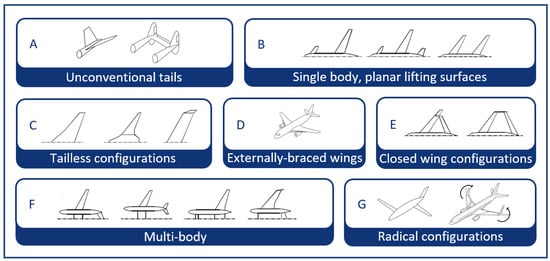
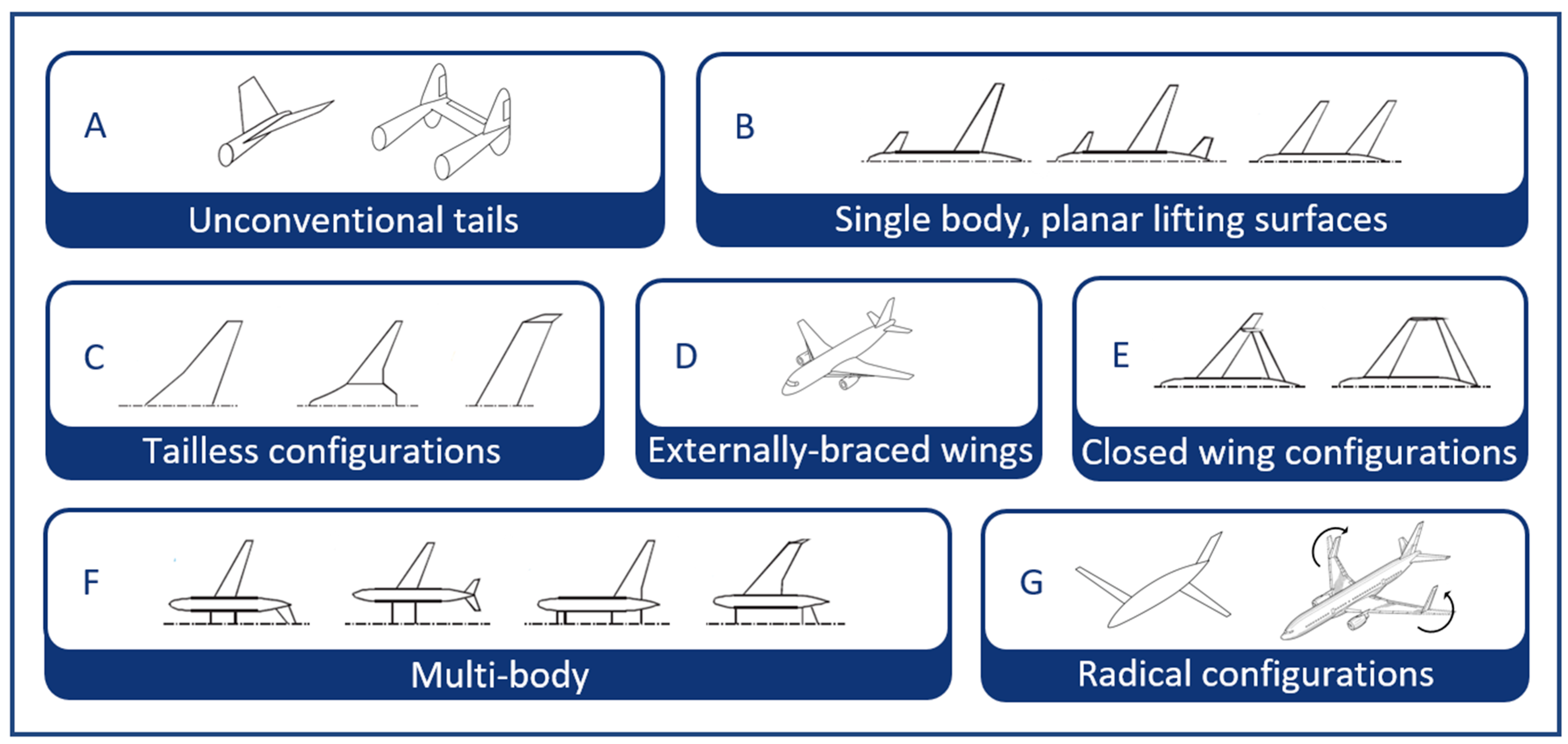
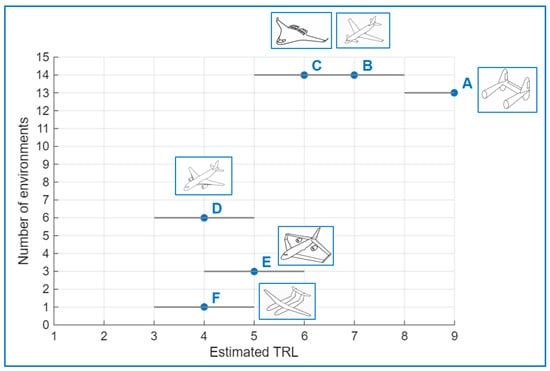
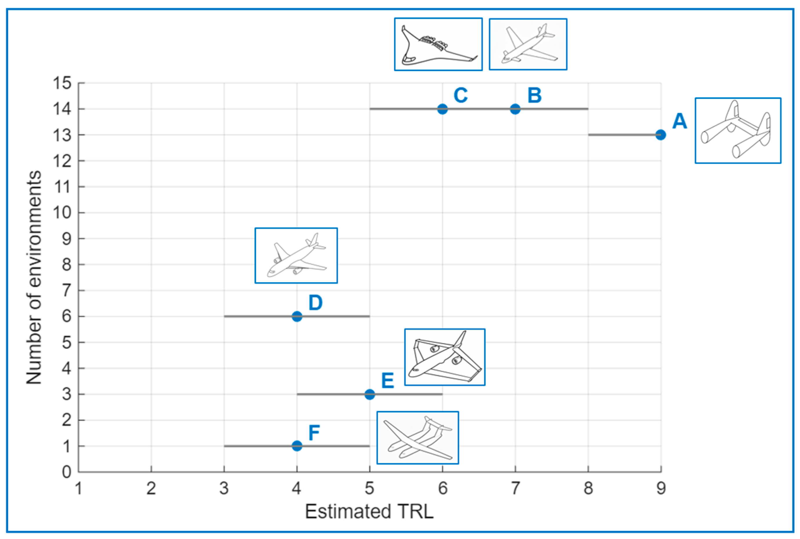
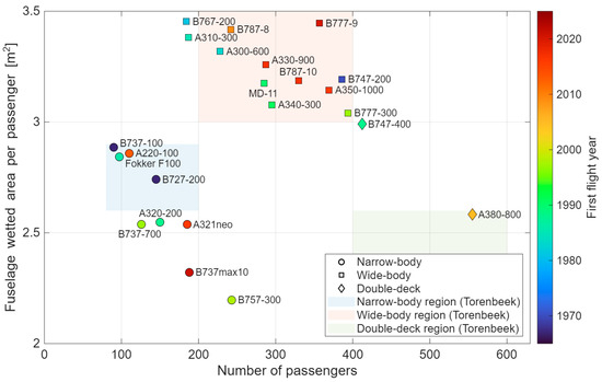
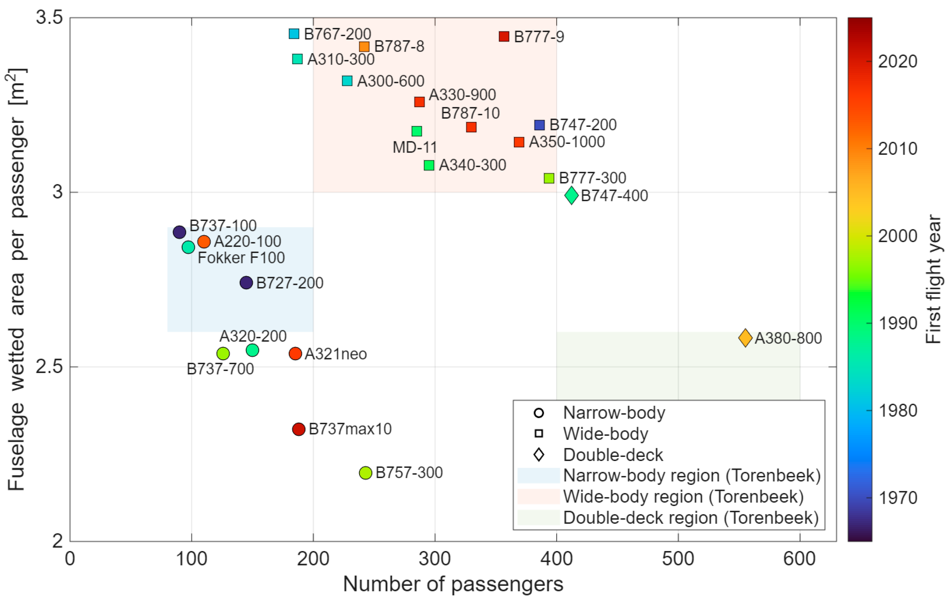
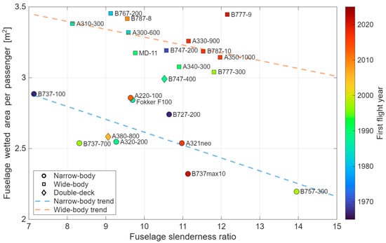
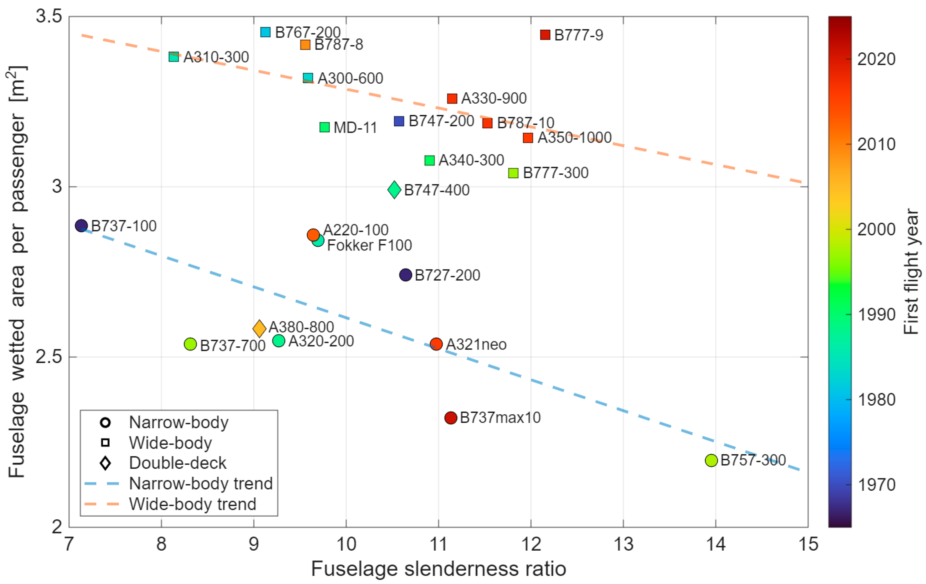


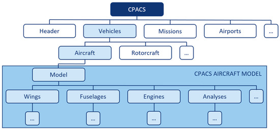
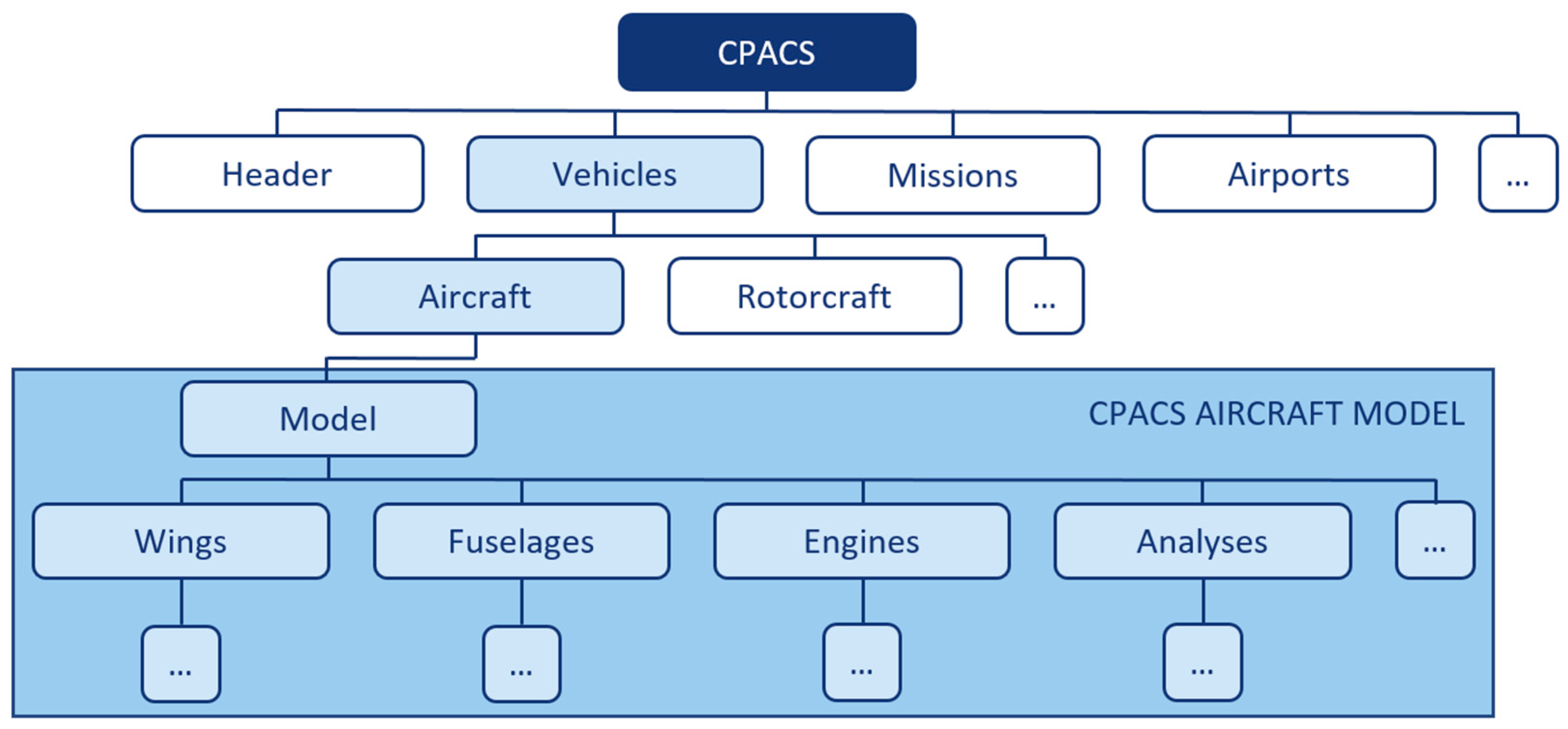
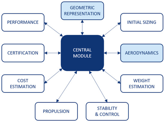
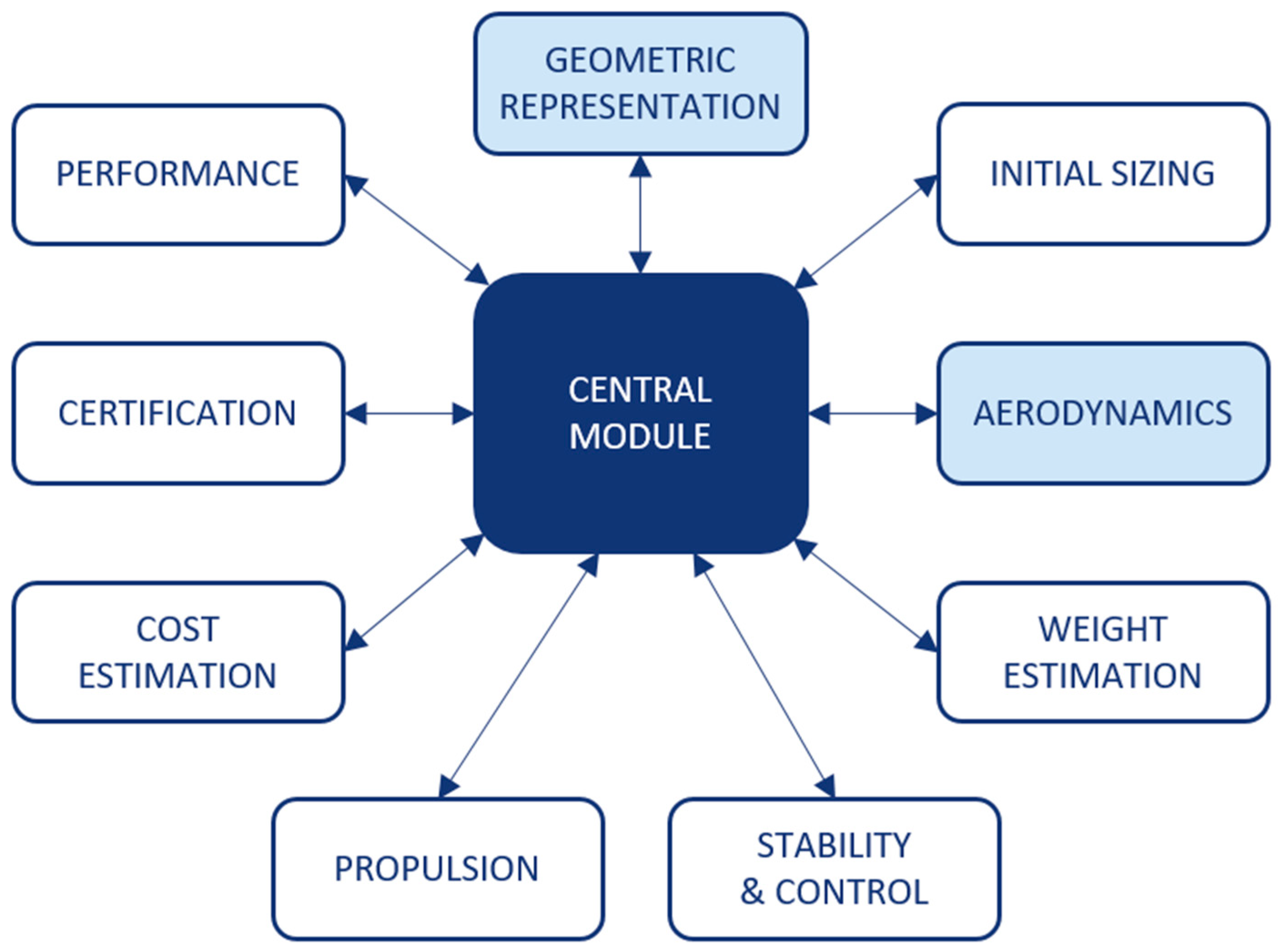
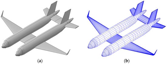
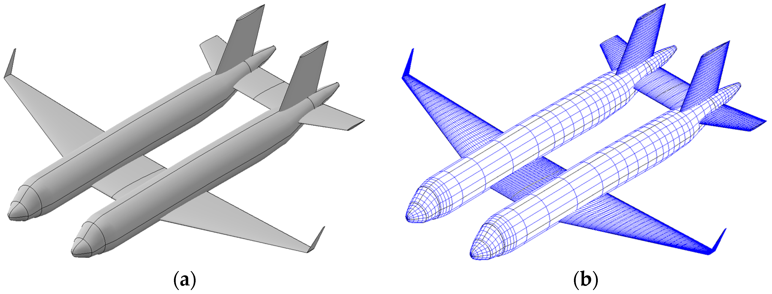

Disclaimer/Publisher’s Note: The statements, opinions and data contained in all publications are solely those of the individual author(s) and contributor(s) and not of MDPI and/or the editor(s). MDPI and/or the editor(s) disclaim responsibility for any injury to people or property resulting from any ideas, methods, instructions or products referred to in the content. |
© 2026 by the authors. Licensee MDPI, Basel, Switzerland. This article is an open access article distributed under the terms and conditions of the Creative Commons Attribution (CC BY) license.