


Abstract
A rapid quasi-one-dimensional (quasi-1D) reacting-flow analysis code was developed for the preliminary assessment of rocket-based combined cycle engines over a broad flight envelope. The internal flow was modeled as steady and quasi-1D in a variable-area duct by solving the coupled conservation equations together with species transport, and finite-rate chemical kinetics were included to represent combustion-induced heat release and composition change. To incorporate configuration-dependent mixing effects that affect RBCC heat release evolution and thermal choking tendencies, a streamwise mixing efficiency distribution was extracted from non-reacting 3D CFD and prescribed as an input to the quasi-1D formulation to represent the progressive availability of reactable fuel along the flowpath. A mode-dependent solution strategy was established by separating the computation into scramjet mode and ramjet mode procedures with a switching criterion based on whether a sonic condition occurs within the combustor, allowing thermal choking and mode transition behavior to be addressed within a single framework. The numerical solver was implemented in Python 3.12.2 and integrated using a stiff ordinary differential equation (ODE) scheme to ensure robust convergence in the presence of reaction-induced stiffness. Verification against previously published hydrogen-fueled scramjet results reproduced the overall streamwise trends of key quantities including Mach number, pressure, temperature, and density. The developed code was then applied to an RBCC configuration under operating conditions representative of ERJ and ESJ regimes, and the quasi-1D predictions were compared with cross-section-averaged 3D RANS CFD results, showing consistent mode identification and comparable axial behavior at a level suitable for preliminary analysis with substantially reduced computational cost.
1. Introduction
Rocket-based combined cycle (RBCC) propulsion integrates a rocket with an airbreathing flowpath to extend operability from static/low-speed conditions to high-speed flight while improving overall specific impulse relative to purely rocket-based propulsion [1,2]. RBCC engines are typically designed to operate across multiple modes (ejector, ramjet, scramjet, and rocket), and past conceptual and demonstration studies have supported their feasibility and highlighted the importance of internal flow optimization across modes [3,4].
One of the primary challenges in RBCC design is that the internal flow is highly coupled and can change abruptly with operating mode. Mode transition, shock–heat release interaction, and heat release-induced thermal choking/unstart can strongly affect combustor flow development and overall performance [5]. While 3D CFD is widely used to analyze these phenomena, preliminary design, trade studies, and sensitivity/optimization loops require rapid evaluation across many geometries and operating points. This motivates reduced-order tools that retain the dominant physics governing choking and mode transition at substantially lower computational cost.
Quasi-one-dimensional (quasi-1D) reacting-flow modeling has been extensively developed for ramjet/scramjet analysis as an efficient alternative for early-stage evaluation. Prior studies can be broadly categorized into three directions. First, quasi-1D frameworks have been formulated for rapid propulsion performance prediction by organizing a consistent governing equation set and numerical procedures suitable for parametric studies over broad operating conditions [6]. Second, finite-rate chemistry has been incorporated to capture non-equilibrium heat release effects and their impact on axial pressure and Mach number evolution, thereby enabling reacting-flow trends to be predicted beyond equilibrium or fixed heat release assumptions [7,8,9]. Third, practical injection/mixing treatments have been introduced and their applicability has been assessed through comparisons with multi-dimensional simulations, indicating that predicted combustor trends can be sensitive to how mixing progress is prescribed and to geometry-dependent flow non-uniformity [10,11]. Collectively, these efforts establish quasi-1D reacting-flow modeling as a computationally efficient approach that can reproduce key axial behaviors relevant to combustor performance, provided that appropriate closure inputs are supplied.
However, directly transferring quasi-1D approaches to RBCC internal flow prediction is not straightforward, and this constitutes a practical gap for preliminary RBCC design. RBCC configurations often feature strong cross-sectional non-uniformity caused by rocket plume–strut/injector interactions; as a result, mixing progress plays an important role in the axial heat release distribution, which in turn controls Mach number evolution and the onset/location of thermal choking and mode transition [5]. In this context, quasi-1D predictions can become overly sensitive if mixing is prescribed in an ad hoc manner rather than reflecting the actual injector/plume-driven 3D mixing behavior. Therefore, an RBCC-oriented quasi-1D framework should (i) incorporate a chemistry/thermochemistry interface that is practical for different fuels and mechanisms, and (ii) employ a physically informed mixing input that reflects geometry- and injection-dependent 3D effects, particularly for thermal choking-based mode identification tasks.
The objective of the present study is to develop a quasi-1D finite-rate reacting-flow modeling framework tailored to RBCC combustor analysis and thermal choking-based mode identification, while leveraging 3D information where it is most critical. Earlier quasi-1D studies have demonstrated the usefulness of reduced-order formulations for rapid propulsion analysis [6] and the practicality of simplified mixing closures for representing fuel–air mixing in a computationally efficient manner [10,11]. However, those approaches were largely developed for simple ramjet/scramjet-type configurations in which the mixing treatment is tied to a particular injection concept or prescribed in an idealized form. In contrast, RBCC internal flows are strongly influenced by rocket plume-driven three-dimensional non-uniformity, so that the streamwise heat release distribution and the onset of thermal choking become sensitive to how mixing is represented. From this standpoint, the innovation of the present work lies in integrating three elements within a single RBCC-oriented quasi-1D framework.
First, an interface is implemented to directly couple CHEMKIN-format reaction mechanisms and thermochemical data, enabling changes in fuel type and kinetic mechanisms through input files without modifying the solver. Second, rather than prescribing an assumed mixing profile, a mixing efficiency distribution is extracted from a non-reacting 3D CFD calculation and supplied to the quasi-1D reacting solver to reflect injector/plume-driven non-uniformity in a computationally efficient manner. Third, the framework is used to predict axial distributions of key flow quantities and, most importantly, to identify operating mode using macroscopic indicators centered on thermal choking—specifically the occurrence and axial location of M = 1 within the combustor and the corresponding cross-sectionally averaged axial trends (e.g., pressure and Mach number). The solver is benchmarked against a previously published quasi-1D scramjet result [6], and the RBCC cases are assessed against cross-section-averaged 3D CFD data with emphasis on mode identification and choking location consistency.
2. Formulation and Numerical Methods
2.1. Governing Equations
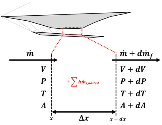
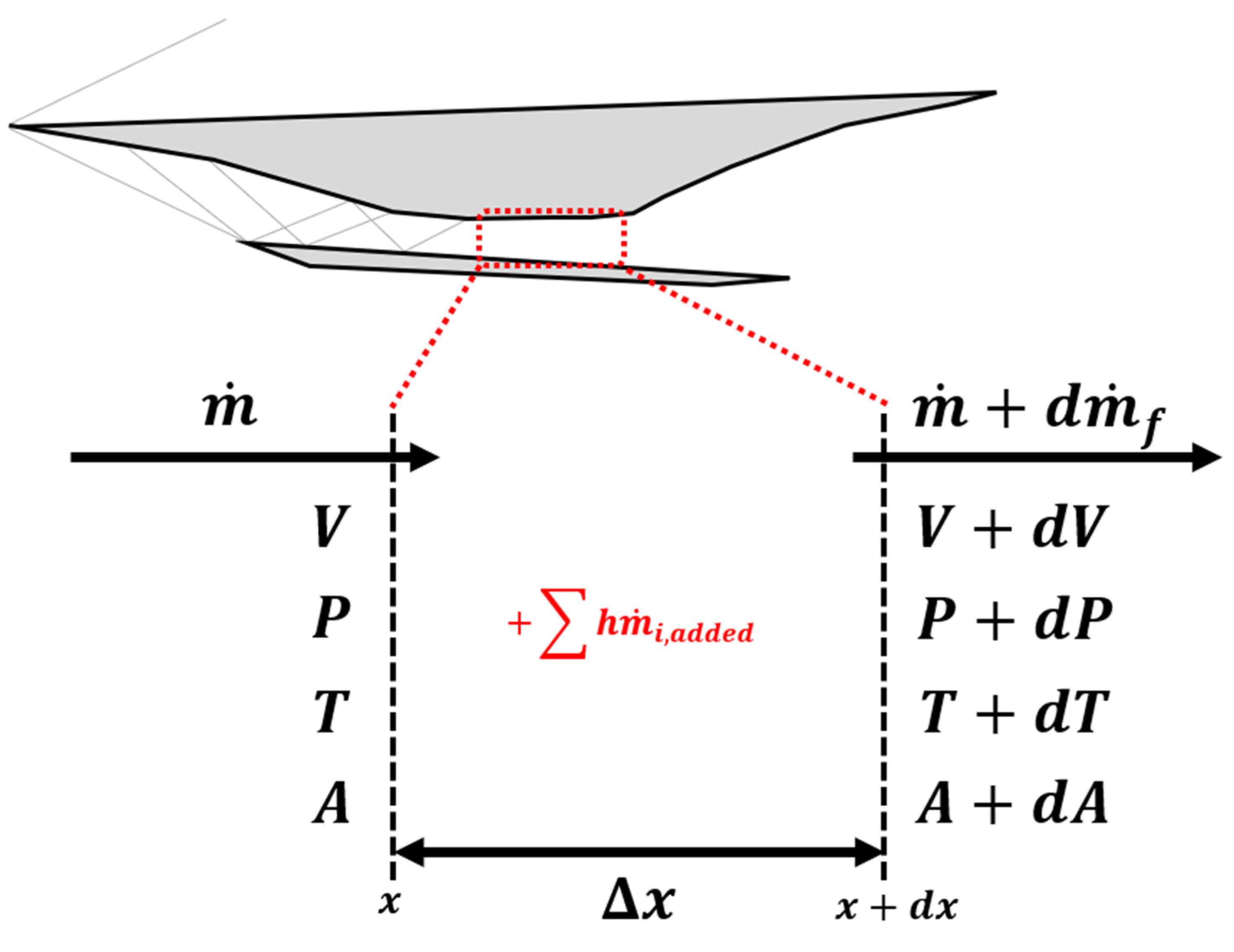
The quasi-1D numerical code developed in this study follows the modeling framework of Torrez et al. [6]. To efficiently describe the coupled flow and reacting processes in the engine flowpath, the flow is assumed to be steady and quasi-1D. The working fluid satisfies the ideal gas equation of state, while the thermodynamic properties are evaluated as functions of temperature. Mixture-averaged thermodynamic properties (e.g., cp, h, and γ) and the mixture molecular weight are updated from the local species mass fractions using the NASA polynomial thermochemistry described in Section 2.4. The flow variables are assumed to vary only in the streamwise direction x. The duct cross-sectional area A(x), is prescribed as a function of x to represent area contraction and expansion along the flowpath. The control volume adopted in the quasi-1D formulation, with fuel added through its boundary, is schematically shown in Figure 1.
Figure 1.
Schematic of the quasi-1D control volume including fuel injection.
The governing equations consist of the continuity equation (Equation (1)), momentum equation (Equation (2)), ideal gas equation of state (Equation (3)), mixture-averaged molecular weight relation (Equation (4)), mass addition relation (Equation (5)), total energy equation (Equation (6)), species transport equations (Equation (7)), and chemical source term expression (Equation (8)).
In these equations, , , and denote the temperature, pressure, and density, respectively, and is the axial velocity. The total mass flow rate is , and denotes the added mass flow rate of -th species. The mixture-averaged molecular weight is , and the stagnation enthalpy is . The specific heat ratio, Mach number, specific heat at constant pressure, and Prandtl number are denoted by , , , and , respectively. The species mass fraction is , and represents the production rate of species . The geometric parameters and denote the cross-sectional area and hydraulic diameter, respectively. The formulation further includes the skin friction coefficient and the fuel jet orientation factor . Wall heat transfer effects are incorporated using the adiabatic wall temperature and the wall temperature .
2.2. Mixing Efficiency Definition and Coupling
In a quasi-1D formulation, all flow variables are assumed to vary only in the streamwise direction x. As a result, the predicted axial heat release distribution, and consequently the Mach number evolution and the onset and location of thermal choking, depends strongly on how fuel–air mixing is modeled. In the present governing equation framework following Torrez et al. [6], mixing enters through the mass addition term , which is intended to represent the streamwise rate at which fuel becomes molecularly mixed and therefore available to participate in combustion, rather than the gross injected mass flow rate.
Torrez et al. [6] developed a fuel–air mixing model primarily under the assumption of transverse sidewall injection into a supersonic core flow. Their model defines mixed fluid using a flammability-based criterion and evaluates the axial rate of mixed fuel formation through an area integral over the region where the local fuel mass fraction lies between lean and rich flammability limits [6].
This approach provides a physically motivated route to construct an axial combustible fuel formation rate and is effective when the dominant mixing mechanism conforms to a jet-in-crossflow picture. Its limitation is that the closure remains strongly coupled to the assumed injection topology and the associated scaling assumptions, so changes in injector arrangement or dominant 3D mixing structures can alter the predicted mixing progress substantially.
Birzer and Doolan introduced a compact mixing efficiency concept in which the fuel available for reaction is expressed as a fraction of the injected fuel mass flow rate, , with η increasing from near zero at injection toward unity over a characteristic mixing length Lmix [8]. In their implementation, the mixing efficiency evolution is constructed from literature-based mixing arguments and empirical constants, and the model is used as an efficient reduced-order representation of mixing-limited behavior.
The principal strength of the η based approach is its simplicity and computational efficiency. Once η(x) or an equivalent Lmix is specified, the streamwise availability of reactable fuel is introduced in a consistent, low-cost manner. The principal limitation is that η(x) depends on injector topology and flowfield non-uniformity. Therefore, adopting a correlation calibrated for one injection concept may lead to large discrepancies when the injection and mixing mechanism differs.
Taken together, these prior approaches highlight a key point for quasi-1D RBCC analysis. When mixing is represented through closures that presuppose a specific injection configuration, changing the injection or plume air interaction mechanism can lead to fundamentally different axial mixing progress and therefore fundamentally different predicted heat release distributions and choking tendencies. This issue is amplified for RBCC configurations with an embedded rocket, where ingested air mixes with a rocket plume containing unburned fuel and the subsequent afterburning process is controlled by strongly three-dimensional, geometry-dependent non-uniformity. Under such conditions, a single canonical mixing closure derived for a particular injection arrangement is unlikely to remain robust across operating points and hardware variations, especially when geometric features such as cavities, backward-facing steps, or flameholding elements strongly influence the streamwise development of mixing.
To address this limitation while retaining the efficiency of quasi-1D analysis, the present study adopts the mixing efficiency concept as the reduced-order representation of streamwise mixing progress but determines ηmix(x) directly from the RBCC configuration using non-reacting 3D CFD. Chemical reactions are disabled while maintaining the same flow and injection conditions, and multiple cross-sectional planes normal to the axial direction are defined. On each plane, the sectional mixing efficiency is defined by Equation (9).
In Equation (9), the equivalence ratio ϕ is evaluated locally from the species mass fractions, and the weighting factor α(ϕ) accounts for reactant limitation by assigning the limiting contribution in fuel rich and fuel lean mixtures. Consequently, the numerator in Equation (9) represents a combustible or reactable portion of the sectional fuel mass flow, and ηmix(x) provides an axial measure of mixing progress suitable for reduced-order coupling. The corresponding added fuel mass flow rate used in Equations (5)–(7) is related to the injected fuel mass flow rate by
Here, denotes the gross fuel mass flow rate supplied to the airstream by the fuel source considered. The resulting mixing efficiency profile can also serve as a practical input over operating ranges in which the dominant mixing region and the overall streamwise development of mixing are expected to remain similar. This treatment is particularly useful for configurations in which internal geometric features strongly influence the mixing process, such as embedded rockets, strut-based injectors, cavities, backward-facing steps, or flameholding elements. In this sense, the present hybrid approach provides a practical means of introducing representative geometry-dependent mixing information into the quasi-1D model while preserving the computational efficiency required for preliminary design and parametric studies.
2.3. Numerical Schemes
To solve the governing equations, the formulation is written as a coupled system of ordinary differential equations in the streamwise coordinate . The solver is developed in an object-oriented Python 3.12.2 environment, and the ODE system is integrated using the solve_ivp routine provided by the SciPy 1.13.0 library [12].
In supersonic combustion, the fluid may undergo rapid changes in temperature and species composition due to strong heat release, and the coupled flow chemistry system can become stiff because the chemical time scales are often much smaller than the characteristic flow time scale. To address stiffness, the implicit Radau integrator available in solve_ivp is employed. This solver belongs to the Runge–Kutta Radau IIA family and is well suited for stiff ODE systems [13]. The integration yielded the streamwise distributions of the relevant flow properties and species mass fractions.
2.4. Chemical Kinetics and Thermochemical Properties
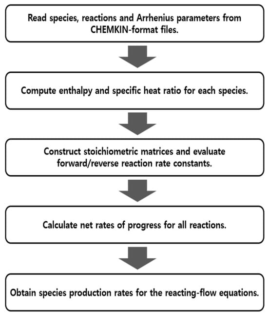
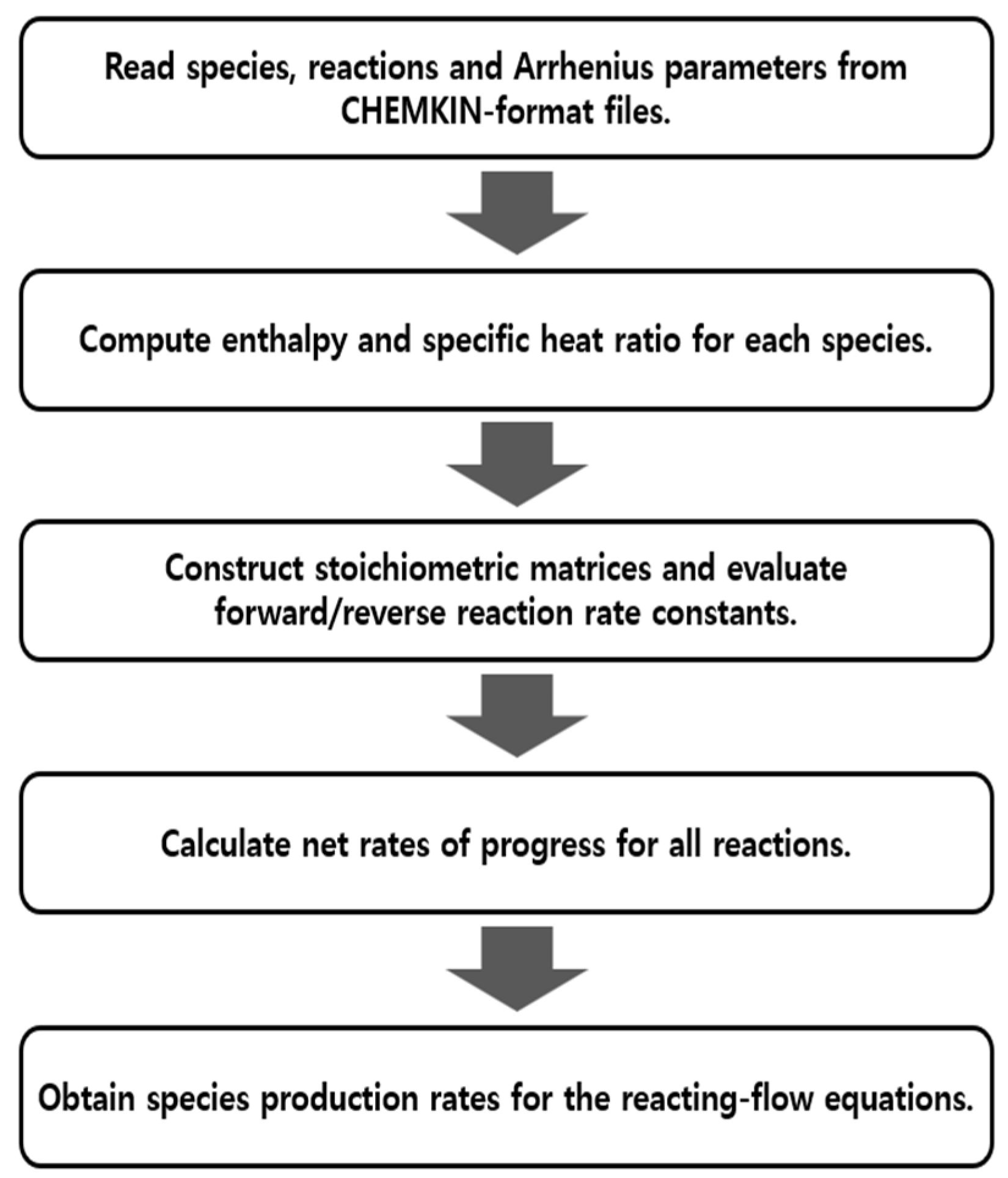
To solve the governing equations introduced in Section 2.1 and to integrate the coupled ODE system described in Section 2.3, chemical kinetics and thermochemical property data are required. In the present study, combustion is modeled using finite-rate chemistry with a multi-step reaction mechanism, and the required inputs are provided in CHEMKIN-format files.
The chemistry procedure implemented in the code is summarized in Figure 2. The solver directly reads a CHEMKIN-format mechanism file and automatically parses the information needed to compute reaction rates. The extracted data include the list of chemical species, elementary reactions, and Arrhenius parameters, which are used to calculate temperature-dependent rate constants.
Figure 2.
Workflow of the CHEMKIN-based thermochemistry and finite-rate kinetics module.
After the species production rates are obtained, the mixture enthalpy and the specific heat at constant pressure are computed to update the energy equation in Section 2.1. Temperature-dependent thermodynamic properties are calculated using the NASA polynomial expressions given in Equations (11) and (12).
The thermochemical coefficients used in Equations (11) and (12) are taken from the NASA Glenn thermochemical database [14]. The solver identifies the species specified in the mechanism file, retrieves the corresponding coefficients, and applies them in the property calculations. This automated procedure reduces input errors, simplifies mechanism replacement, and allows the present framework to be readily extended to different fuels, including kerosene, when the corresponding reaction mechanisms and thermochemical data are provided.
3. Mode Determination and Solution Procedure
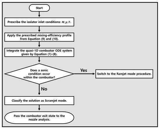
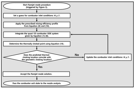
Solving the quasi-1D governing equations described in the previous section yields two distinct combustor regimes. In the scramjet mode, supersonic combustion is maintained throughout the combustor. In the ramjet mode, heat release drives the flow to a sonic condition within the combustor. Because the flow structure and the required boundary treatment differ depending on the presence of a sonic point, the solution procedure is separated into scramjet mode and ramjet mode computations. The corresponding procedures are summarized in Figure 3 and Figure 4, respectively.
Figure 3.
Flowchart of the scramjet mode analysis and switching criterion for ramjet mode computation.
Figure 4.
Ramjet mode solution procedure with inlet condition iteration.
3.1. Scramjet Mode Procedure
Figure 3 outlines the workflow used for the scramjet mode analysis and the switching criterion for the ramjet mode computation. The isolator inlet conditions are prescribed as the initial conditions for the scramjet mode integration of the combustor. At this stage, pre-combustion shock trains in the isolator are not considered, and they are addressed only in the ramjet mode procedure. After the integration, the operating mode is determined by whether a sonic condition occurs within the combustor. If the flow remains supersonic throughout the combustor, then the solution is classified as scramjet mode and the combustor exit state is passed to the nozzle analysis as a downstream boundary condition. Otherwise, if a sonic point appears within the combustor, the procedure switches to the ramjet mode analysis.
3.2. Ramjet Mode Procedure
Figure 4 summarizes the solution procedure for the ramjet mode. In this mode, thermal choking in the combustor generates an upstream-propagating pressure disturbance, which in turn produces a pre-combustion shock train in the isolator. In the present study, the isolator shock train is predicted using the isolator model proposed by Lin et al. [15]. In addition, the combustor inlet condition is iteratively adjusted so that the predicted thermal choking location coincides with the geometric choking location, as indicated in Figure 4.
The isolator model uses different correlations depending on the duct cross-sectional geometry. Equation (13) is used for a rectangular cross-section, whereas Equation (14) is used for a circular cross-section.
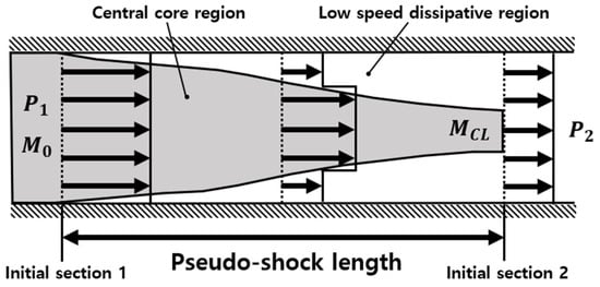
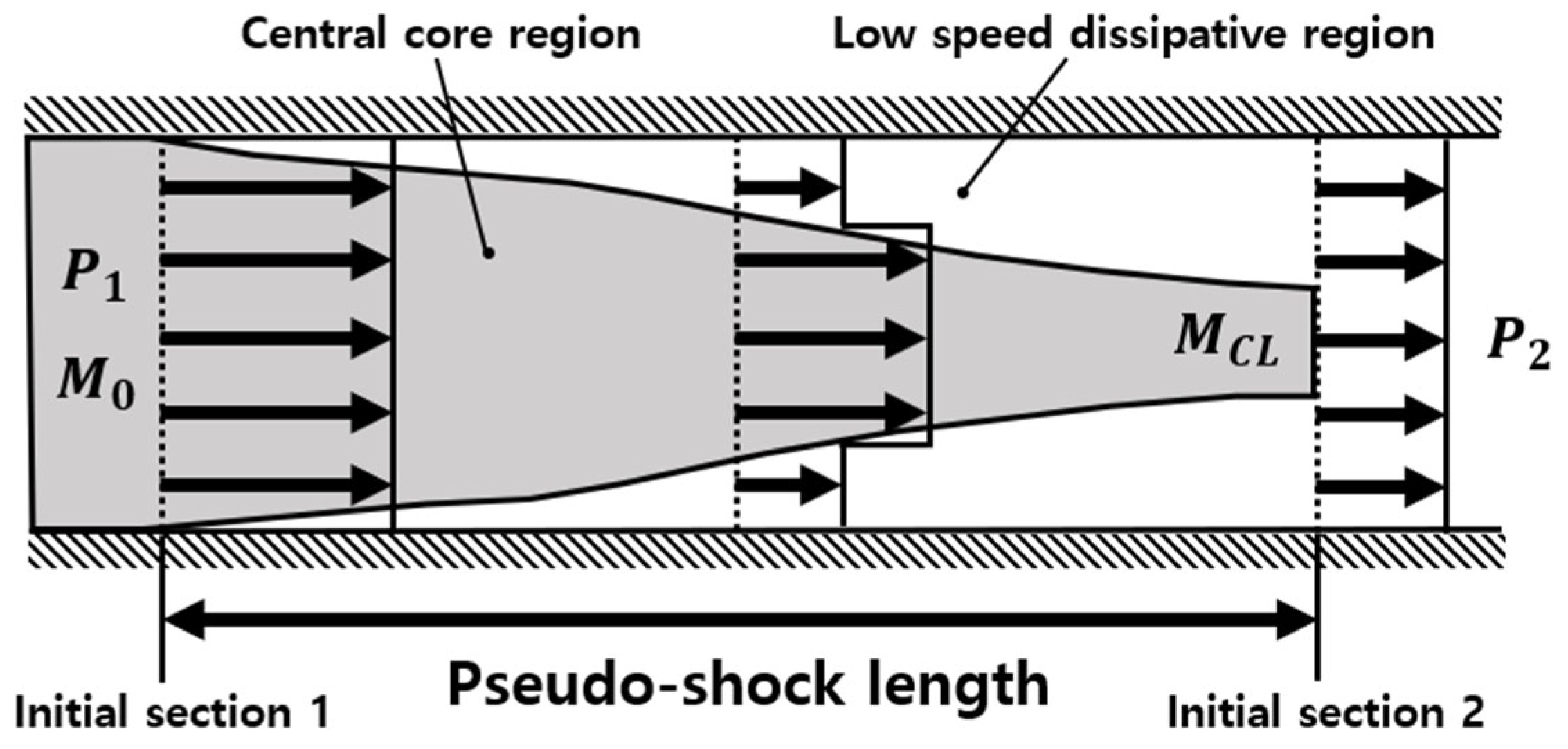
In Equations (13) and (14), denotes the Mach number of the core flow at the isolator exit centerline (see Figure 5), and is the Mach number at the isolator inlet. The pressure ratio is defined as the ratio of the isolator exit static pressure to the isolator inlet static pressure .
Figure 5.
Schematic of the isolator pseudo-shock structure in ramjet mode operation.
Using the isolator model, the isolator exit static pressure and Mach number are obtained, and the corresponding exit temperature is then computed from isentropic relations. The resulting isolator exit Mach number, pressure, and temperature are used as the initial conditions for the ramjet mode combustor calculation. The thermal choking location inside the combustor is determined using the relations proposed by Shapiro in Equations (15)–(17) [16].
As indicated by Equation (17), the sonic point () introduces a singularity because the denominator vanishes. To obtain a physically admissible solution that passes through the sonic condition, the expression must approach an indeterminate form at , which requires the numerator to satisfy at the sonic point. In this study, L’Hôpital’s rule is applied to define the limiting form when both the numerator and denominator approach zero, enabling the solution to be continued through the sonic point.
In the present implementation, is computed using Equation (18). An iterative procedure is then performed to locate the thermally choked point satisfying by adjusting the combustor inlet Mach number. Practical numerical tolerances are introduced to identify the sonic condition in a manner suitable for repeated quasi-1D calculations while maintaining solution accuracy. Accordingly, the sonic condition is regarded as satisfied when the local Mach number falls within and the choking function criterion satisfies .
The geometric choking location is defined as the axial position where the constant-area combustor section ends and the diverging section begins. The iteration is initialized with a user-specified inlet Mach number. If the choking location predicted from the solution does not coincide with the geometric choking location, the inlet Mach number is updated and the same procedure is repeated, with the update step progressively reduced as the predicted choking location approaches the target location. The converged solution is accepted when the difference between the predicted thermal choking location and the geometric choking location is within 1.5%. Under these criteria, the iterative procedure typically converged within 20 iterations.
After the ramjet mode combustor solution is obtained, the combustor exit state is passed to the nozzle analysis as a downstream boundary condition to compute the nozzle expansion and thrust.
4. Model Verification
4.1. Benchmark Configuration and Operating Conditions
To assess the reliability of the developed numerical code, verification was performed by comparing the present results with those reported by Torrez et al. [6]. The reference study considered hydrogen as the fuel, and the same fuel was adopted here. Chemical kinetics were modeled using the hydrogen–air mechanism proposed by Saxena et al. [17], which consists of 11 species and 30 reactions. The mechanism has been reported to reproduce key hydrogen combustion characteristics across a range of experimental datasets, including laminar flame speeds, diffusion flame extinction limits, and ignition delay times.
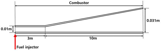
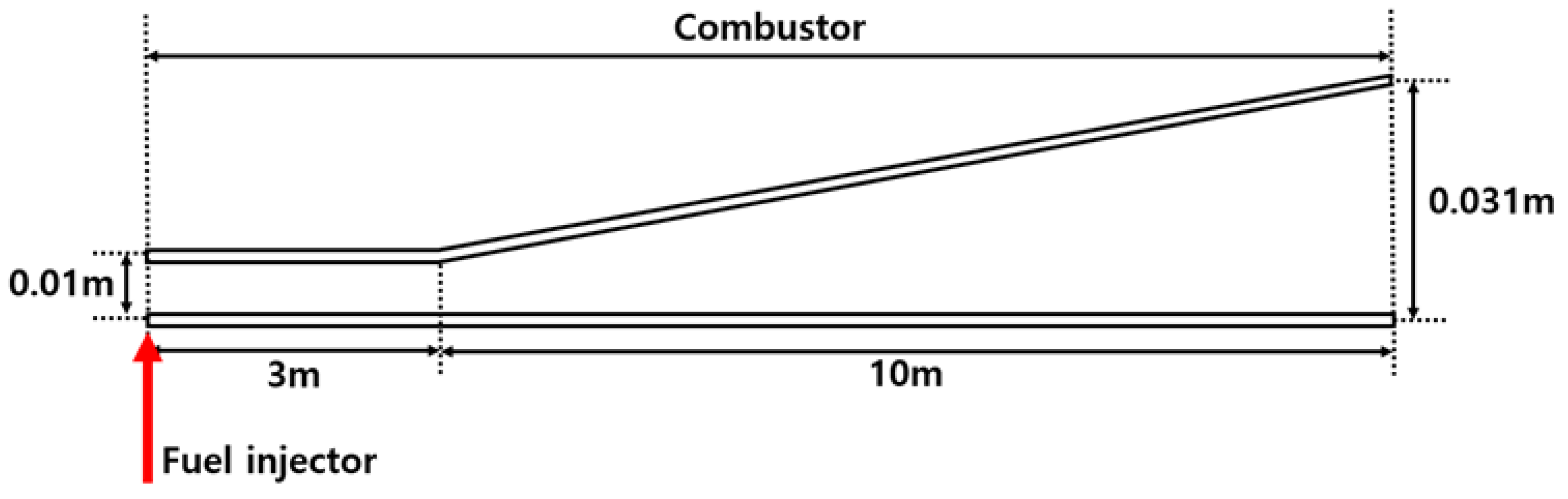
The verification geometry is shown in Figure 6. The total length of the configuration is 13 m, consisting of a 3 m combustor followed by a 10 m nozzle. The fuel injector is located at the combustor inlet, and the inlet-to-exit area ratio is 3.1. Because the inlet throat length and combustor width were not specified in the reference study, they were assumed to be 0.01 m and 0.196 m, respectively, in the present simulations.
Figure 6.
Geometry of the benchmark combustor–nozzle configuration.
The operating conditions are summarized in Table 1. The inflow Mach number at the combustor inlet was set to 3. The inlet air composition was specified on a mass basis as 23.3% oxygen and 76.7% nitrogen. Two equivalence ratio cases were considered for the injected fuel, namely and .
Table 1.
Operating conditions for the benchmark configuration.
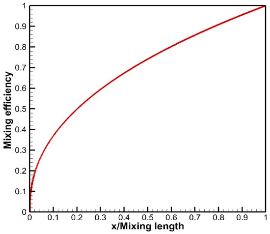
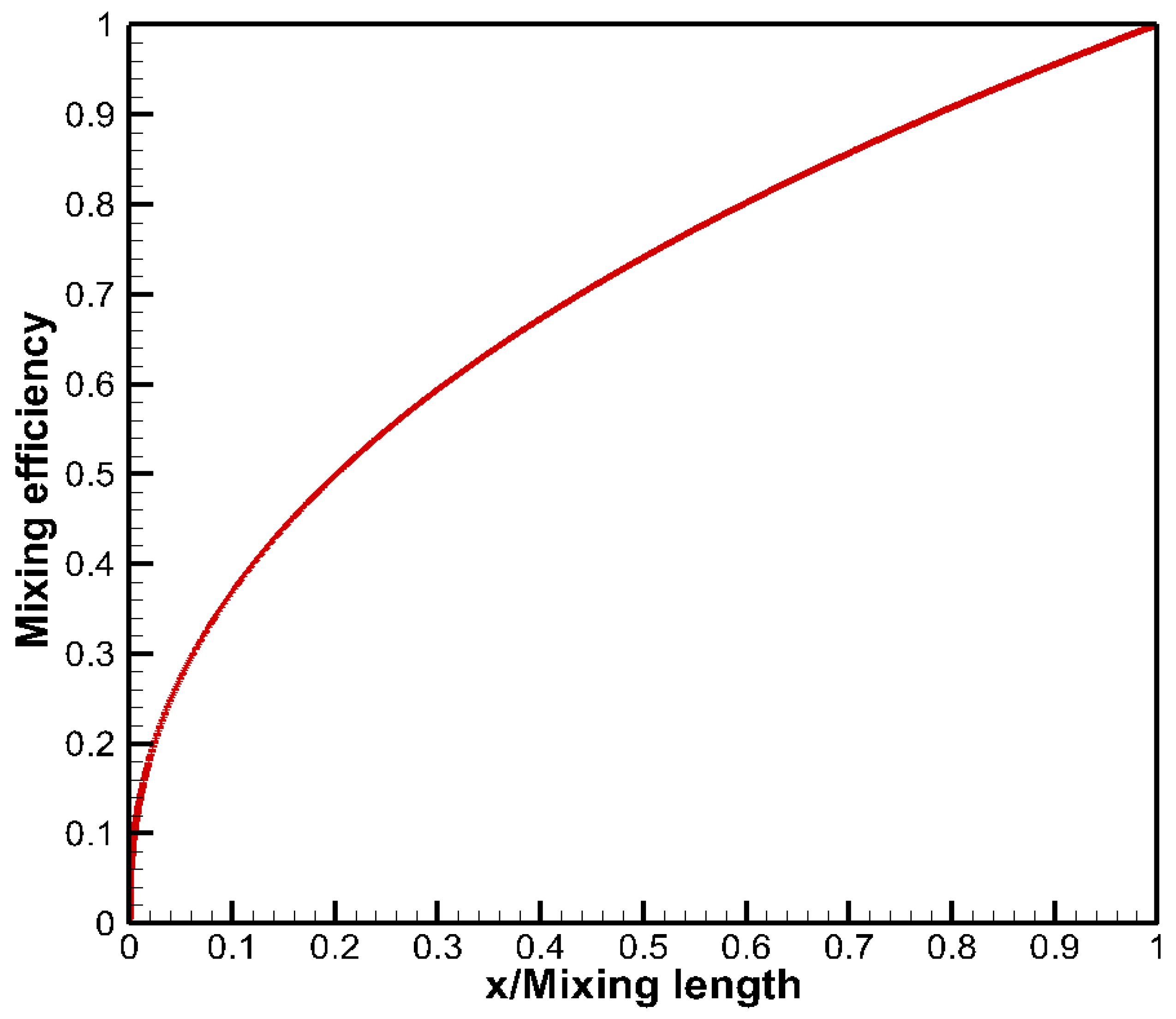
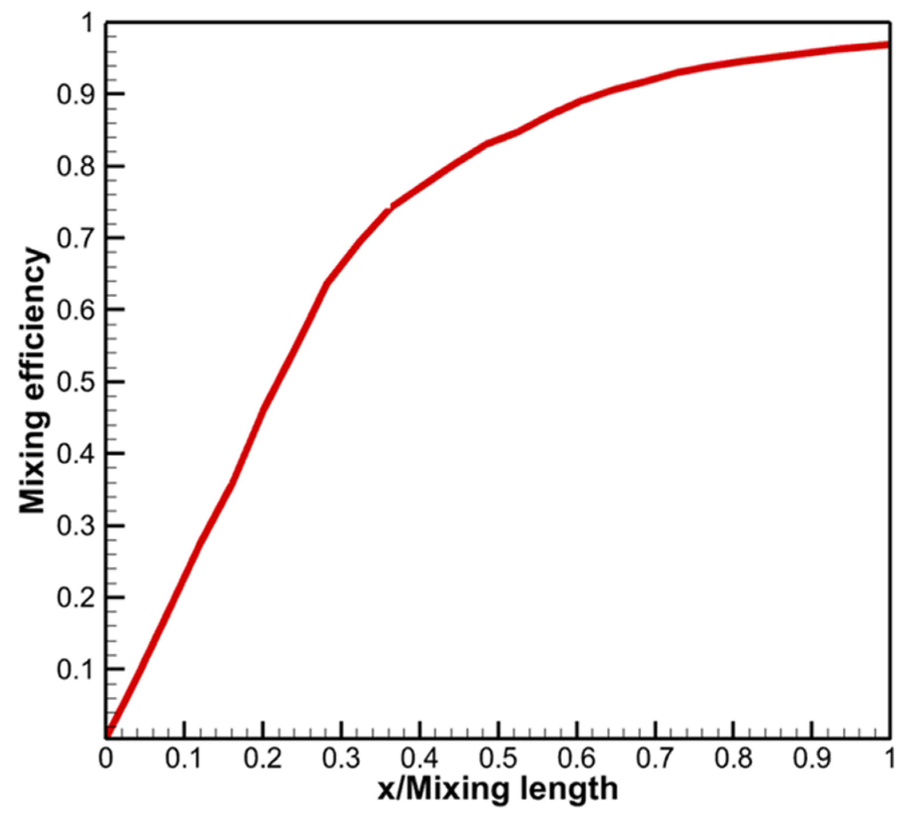
The mixing length was set to 1 m following Torrez et al. [6]. While the reference study also relied on an assumed mixing model, it did not provide a detailed spatial distribution of the mixing efficiency. Accordingly, for the verification calculations in this section, the power law mixing efficiency profile shown in Figure 7 was prescribed. It should be noted that this profile was introduced only as an assumed verification input and was not extracted from non-reacting 3D CFD. To facilitate ignition, a small amount of radical species was included in the initial condition.
Figure 7.
Prescribed mixing efficiency distribution along the normalized mixing length.
4.2. Verification Results and Discussion
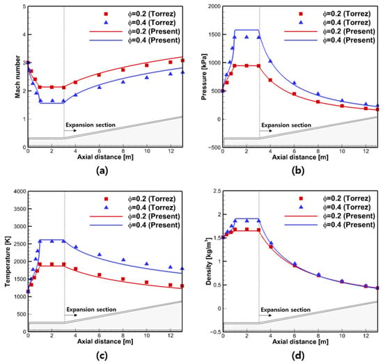
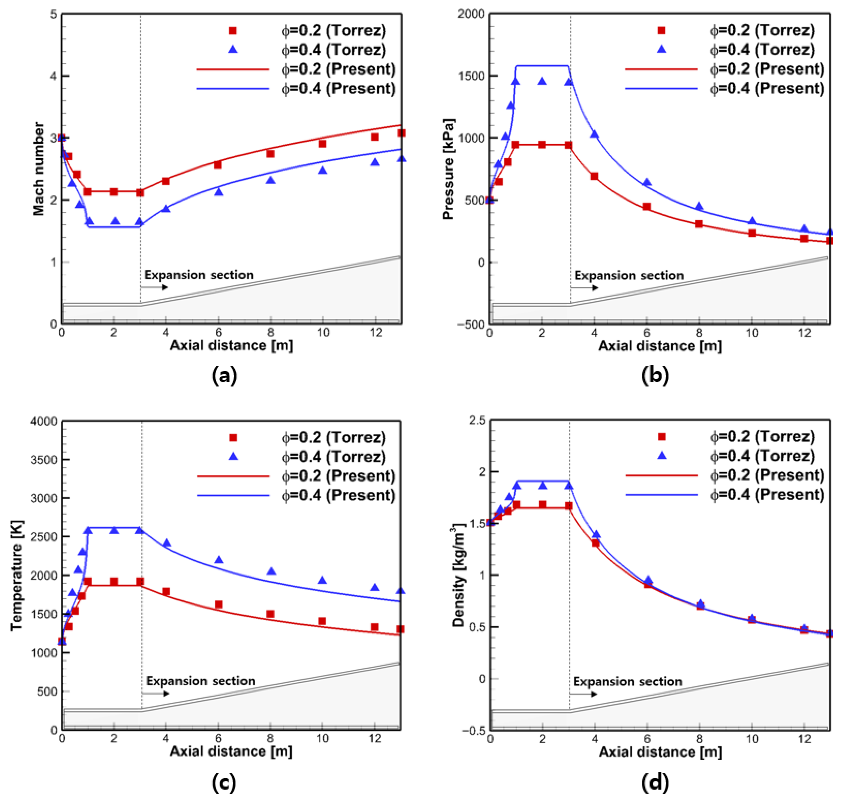
Verification was conducted by comparing the present quasi-1D predictions with the results reported by Torrez et al. [6]. Figure 8, Figure 9 and Figure 10 show the streamwise distributions of Mach number, static pressure, static temperature, and density for the two equivalence ratio cases, and . In both cases, the flow remains supersonic over the entire flowpath, indicating that the combustion-induced pressure rise is insufficient to trigger thermal choking under the present conditions. Accordingly, the solutions correspond to scramjet mode operation.
Figure 8.
Streamwise distributions for the benchmark configuration at and : comparison between Torrez et al. [6] and the present results: (a) Mach number; (b) static pressure; (c) static temperature; (d) density.
Figure 9.
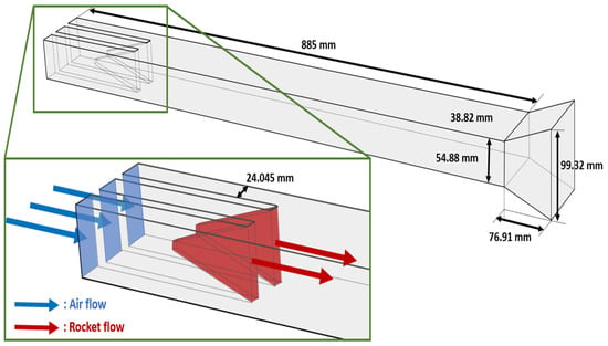
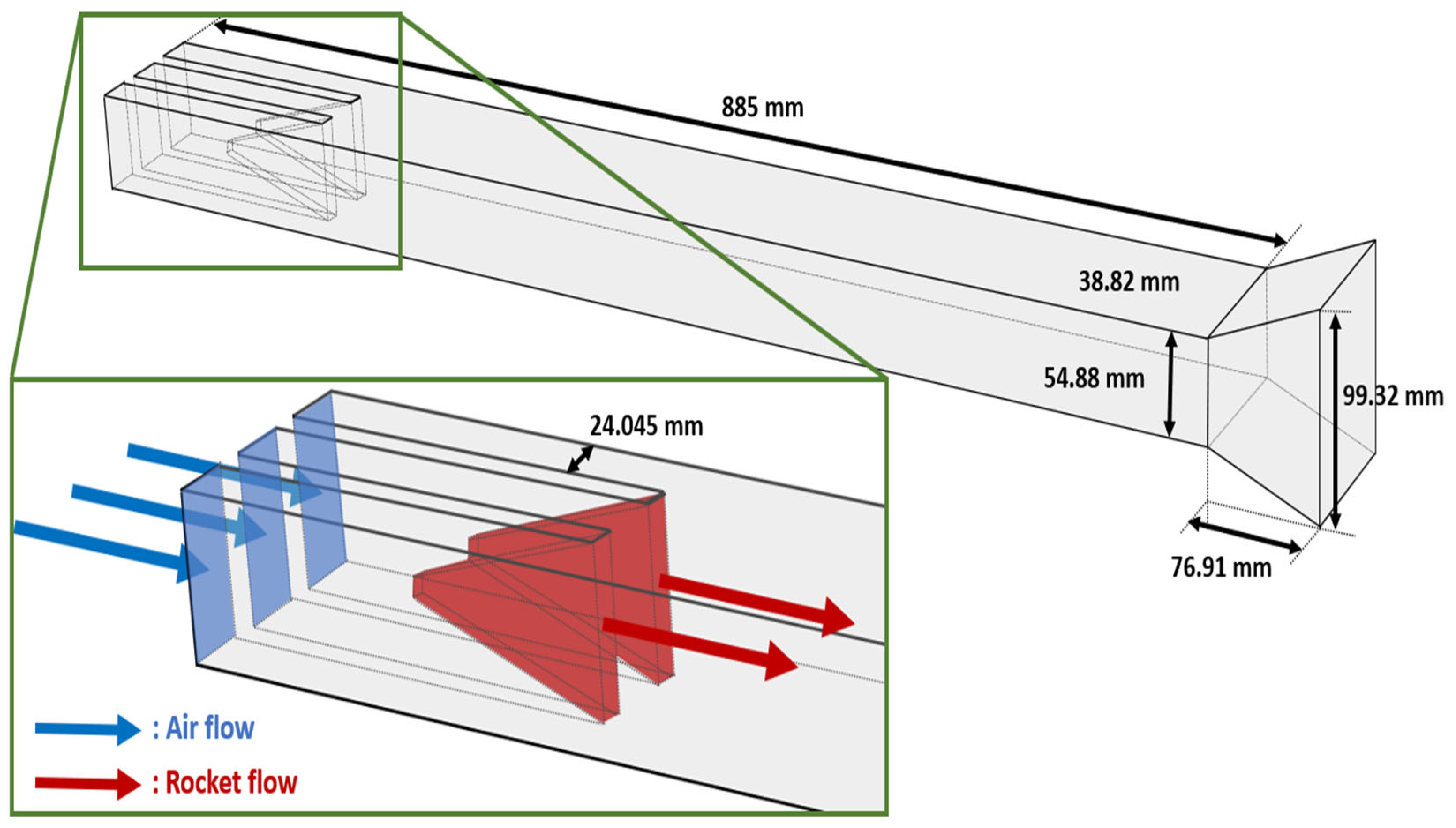
Schematic of the RBCC engine configuration.
Figure 10.
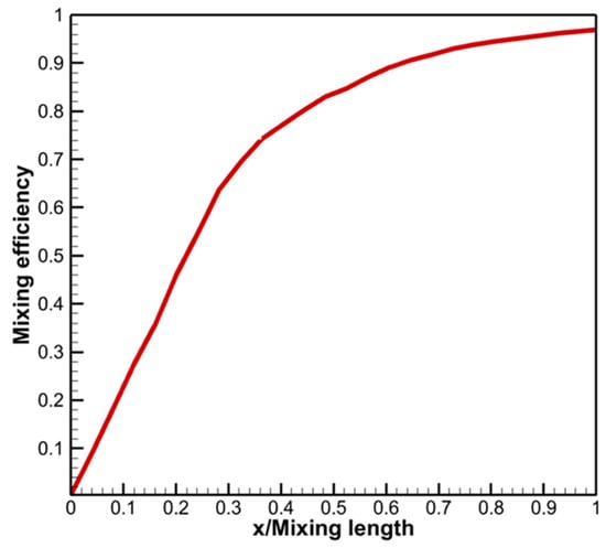
Streamwise distribution of the mixing efficiency .
In the upstream combustor region (), fuel injection initiates rapid combustion and the thermodynamic state changes noticeably. As shown in Figure 8b,c, pressure and temperature increase due to heat addition from combustion. Over the same region, the Mach number decreases gradually, which is consistent with the increase in the local speed of sound with temperature and the decelerating tendency of heat addition in a constant-area supersonic flow. The density distribution in Figure 8d varies in accordance with the concurrent changes in pressure and temperature through the equation of state.
In the constant-area section of the combustor (), the flow variables exhibit relatively weak streamwise variation and approach nearly constant levels. This behavior suggests that mixing and the major combustion reactions have progressed substantially, so additional heat release is limited.
Downstream of the combustor, in the diverging section () the increasing area drives supersonic expansion. In this region, the Mach number increases while pressure, temperature, and density decrease, showing the typical trends of nozzle expansion.
Overall, the present results reproduced the main trends and profiles reported in the reference study [6], although quantitative differences were observed in some regions. These differences were attributed to the limited information provided in the reference regarding wall heat transfer conditions, friction modeling, the prescribed power law mixing efficiency profile, geometric definition, and ignition-assisting initialization. In particular, the early combustion region was sensitive to the prescribed mixing efficiency distribution, which could influence the rate of heat release and the resulting gradients of the flow variables.
5. Application to an RBCC Engine
In this section, the developed quasi-1D code is applied to an RBCC engine configuration to investigate mode-dependent internal flow characteristics. The quasi-1D predictions are also compared with 3D CFD results to examine the applicability of the proposed modeling approach.
5.1. RBCC Geometry and Operating Conditions
The RBCC configuration considered in this study was selected based on a previous investigation on embedded-rocket configurations [18]. In that study, a strut-type injector showed higher combustion efficiency than other injector concepts. Accordingly, the strut-type injector was adopted as the baseline configuration in the present work. The overall geometry and key dimensions are shown in Figure 9.
As illustrated in Figure 9, the embedded rocket is mounted along the combustor centerline in the form of a strut. The inlet cross-sectional area of the embedded rocket is 31.94 mm2. The flow is assumed to be choked at this inlet, and the rocket plume is discharged from the embedded rocket into the combustor.
Two operating modes are defined in this study: ejector ramjet (ERJ) mode and ejector scramjet (ESJ) mode. The flight conditions were chosen to represent typical RBCC operating points: a flight Mach number of 3 at an altitude of 12 km for ERJ operation, and a flight Mach number of 6 at an altitude of 26.54 km for ESJ operation. For each flight condition, two rocket chamber pressures were considered, resulting in four cases in total. The operating conditions are summarized in Table 2.
Table 2.
Operating conditions for the RBCC engine configuration.
To provide the quasi-1D model with a mixing efficiency distribution representative of the RBCC configuration, ηmix(x) is evaluated from the non-reacting 3D CFD solution using the sectional definition given in Equation (9). The resulting axial distribution ηmix(x) is then prescribed as an input to the quasi-1D mixing treatment through Equation (10). The extracted ηmix(x) profiles for the RBCC cases considered in this study are presented in Figure 10.
5.2. 3D CFD Setup
Reacting 3D CFD simulations were performed for the RBCC configuration under the operating conditions described in the previous section to enable comparison with the quasi-1D predictions. The corresponding non-reacting simulations used to evaluate the axial mixing efficiency distribution ηmix(x) were described in Section 5.1. ANSYS Fluent 2023 R1 was used to solve the Reynolds-averaged Navier–Stokes equations with the conservation of mass, momentum, and energy. A density-based solver was employed to treat the compressible flow effects over the present range of subsonic to supersonic regimes, and a second-order upwind scheme was used for spatial discretization.
Turbulence was modeled using the SST model, which is widely used for internal flows where near-wall behavior and adverse pressure gradient effects are important [19]. Turbulence–chemistry interaction was represented using the finite-rate/eddy dissipation model [20]. For chemical kinetics, the built-in single-step global CH4–air mechanism in ANSYS Fluent 2023 R1 was adopted [21]. This modeling choice is consistent with the objective of the present 3D CFD analysis, which is to provide a practical reference for the macroscopic flow behavior relevant to RBCC mode assessment, including mode classification and the cross-section-averaged axial trends of M, p and T. In particular, the reacting 3D CFD is intended to capture the dominant heat release effect governing the overall streamwise flow evolution and the occurrence of thermal choking, which are the key quantities of interest in the present quasi-1D/3D comparison. Accordingly, the comparison is focused on mean axial behavior and mode identification-related trends, rather than on detailed local reacting structures or intermediate species distributions.
A mesh sensitivity study was conducted using three grid levels with approximately 0.3 million, 0.9 million, and 1.5 million cells. The 0.3-million-cell mesh was insufficient to reproduce the location and intensity of localized thermal choking. In contrast, the 0.9-million- and 1.5-million-cell meshes produced differences of less than 2% in wall pressure distributions and thrust. Considering the balance between accuracy and computational efficiency, the 0.9-million-cell mesh was selected for the final simulations.
5.3. 3D CFD Results
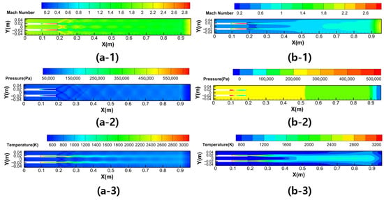
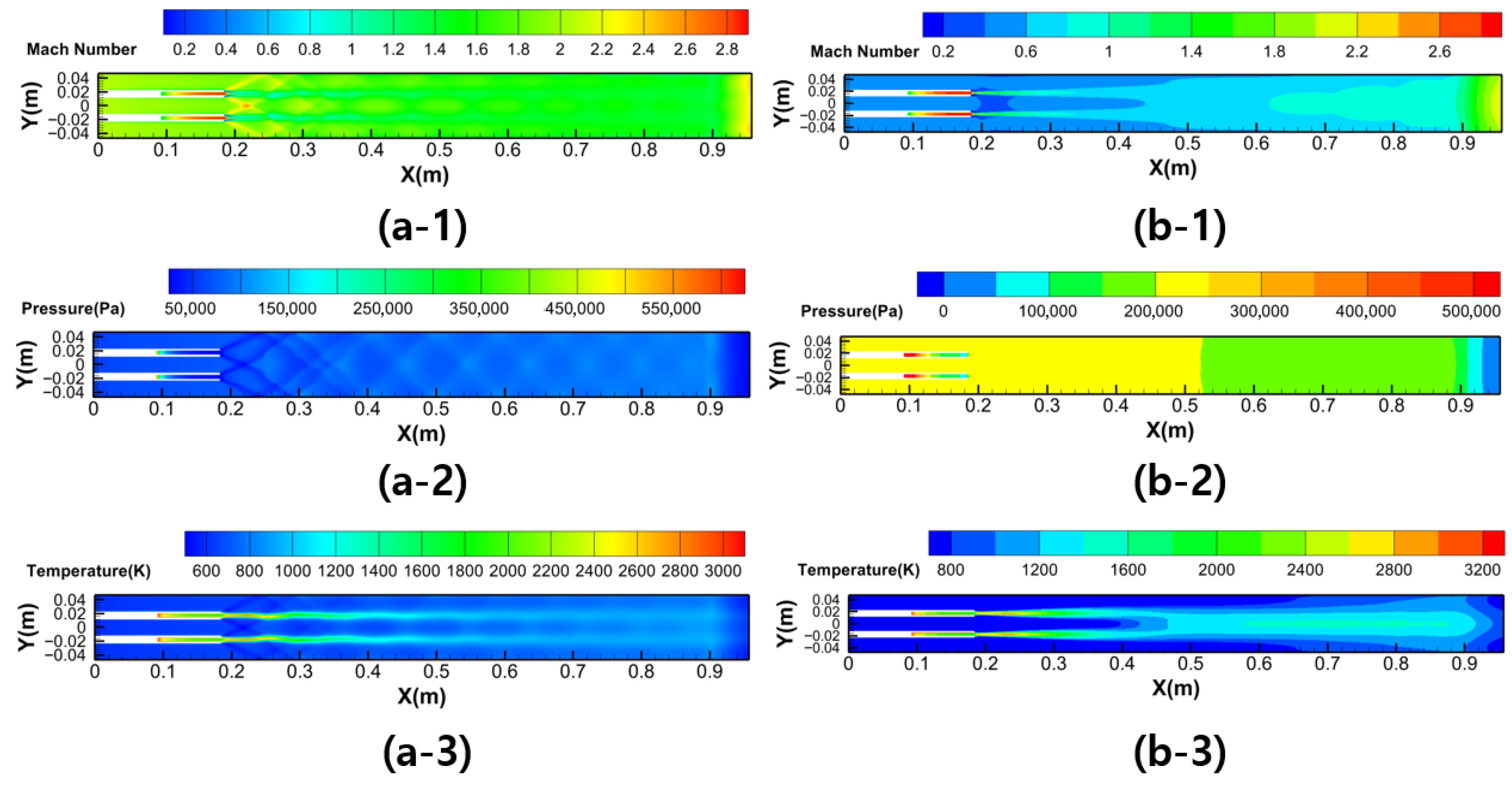
Figure 11 presents the contours of the reacting 3D CFD results for Case 1 (M∞ = 3, h = 12 km) at two rocket chamber pressures, Pc = 11 and 50 bar. To describe the internal flow features, Mach number, static pressure, and static temperature contours are shown on the top-view plane.
Figure 11.
Top-view contours of 3D CFD results for Case 1 ( km) at two rocket chamber pressures. (a-1) Mach number contour at bar; (a-2) static pressure contour at bar; (a-3) static temperature contour at bar; (b-1) Mach number contour at bar; (b-2) static pressure contour at bar; (b-3) static temperature contour at bar.
Figure 11(a-1–a-3) correspond to the lower-chamber-pressure condition (11 bar). In Figure 11(a-1), the Mach number field shows that the flow remains supersonic throughout the engine, with no evident transition to subsonic conditions. The static pressure contours in Figure 11(a-2) highlight shock structures formed around the strut and along the engine walls. In this case, the relatively weaker heat addition is associated with the lower-chamber-pressure condition, and thermal choking is not observed within the flowpath. Accordingly, the shock-related structures persist into the downstream region.
Figure 11(b-1–b-3) correspond to the higher-chamber-pressure condition (50 bar). The static temperature contours in Figure 11(b-3) show an expanded high-temperature region around the rocket plume, indicating stronger heat release compared with the previous case. With this increased heat addition, thermal choking occurs near the nozzle throat region. Consistent with this behavior, Figure 11(b-1) shows a rapid reduction in Mach number and the development of a subsonic region, after which the flow exhibits characteristics of subsonic combustion-dominated operation.
Overall, the Mach number 3 condition―often associated with ERJ mode―can exhibit markedly different internal flow characteristics depending on the rocket chamber pressure, ranging from a supersonic flow regime with maintained shock structures to a thermally choked regime with a distinct subsonic region.
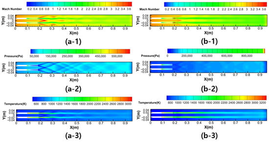
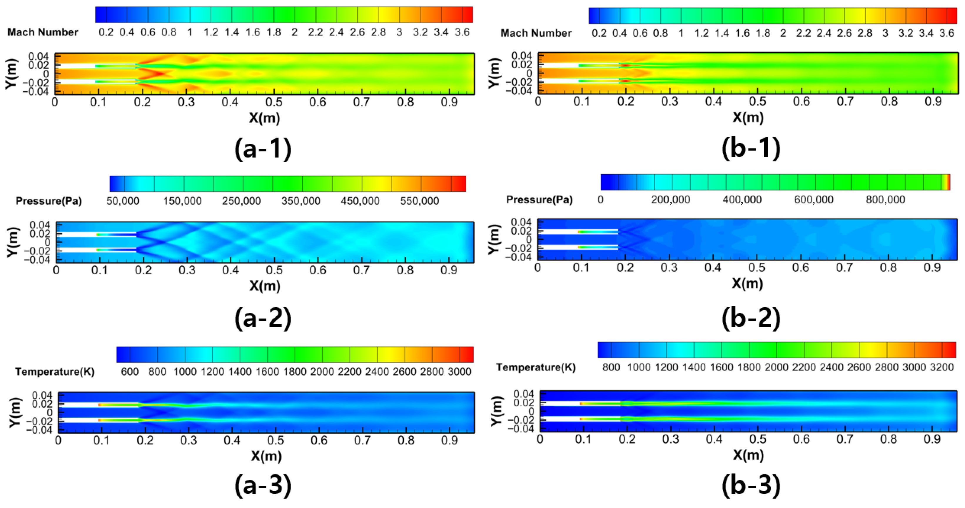
Figure 12 presents the top-view contours of the reacting 3D CFD results for Case 2 (M∞ = 6, h = 26.54 km). The effects of rocket chamber pressure are illustrated using Mach number, static pressure, and static temperature contours.
Figure 12.
Top-view contours of 3D CFD results for Case 2 ( km) at two rocket chamber pressures. (a-1) Mach number contour at bar; (a-2) static pressure contour at bar; (a-3) static temperature contour at bar; (b-1) Mach number contour at bar; (b-2) static pressure contour at bar; (b-3) static temperature contour at bar.
Figure 12(a-1–a-3) correspond to the lower-chamber-pressure condition (11 bar). In Figure 12(a-1), the Mach number field indicates a substantially higher inflow Mach number at the combustor entrance compared with the lower M∞ case in Figure 11(a-1). Consistent with this trend, the static pressure contours in Figure 12(a-2) exhibit stronger shock structures, reflecting the higher incoming flow speed. The static temperature field in Figure 12(a-3) shows that the dominant high-temperature region is associated with the rocket plume, while the additional temperature rise attributable to combustion remains relatively limited.
Figure 12(b-1–b-3) correspond to the higher-chamber-pressure condition (50 bar). In Figure 12(b-1), the Mach number distribution exhibits a moderate reduction relative to Figure 12(a-1), consistent with increased heat addition under the higher fuel flow rate. Nevertheless, no distinct subsonic region is observed within the engine, and the flow remains supersonic over the entire flowpath. Accordingly, the overall flowfield retains characteristics consistent with supersonic combustion-dominated operation under this condition.
5.4. Comparison of Quasi-1D and 3D CFD Results
In the quasi-1D analysis, the methane–air skeletal mechanism proposed by Larsson et al. [22] was adopted to provide a practical level of kinetic fidelity for capturing macroscopic heat release effects relevant to mode assessment, including thermal choking behavior. The base mechanism consists of 17 species and 42 reactions, and its capability has been reported through comparisons with the detailed GRI 3.0 mechanism in terms of ignition delay, flame temperature, flame speed, major species and most minor species, and extinction limits [22]. This choice is well suited for iterative quasi-1D calculations, as it retains computational efficiency while allowing heat release- and composition-driven variations in the flow variables to be represented in a physically meaningful manner.
To enable a quantitative comparison on a common basis, the 3D CFD solutions were reduced to streamwise profiles by cross-sectional averaging. On each plane normal to the streamwise direction, area-weighted averaging was applied to extract the Mach number, static pressure, and static temperature. These reduced quantities provide representative mean values that can be directly compared with the quasi-1D predictions.
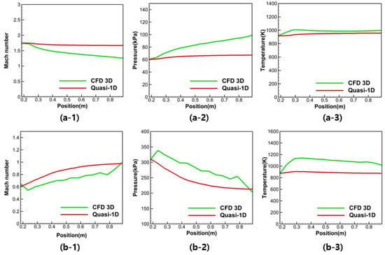
Figure 13 compares the quasi-1D predictions with the cross-section-averaged 3D CFD results for Case 1. Figure 13(a-1–a-3) correspond to the lower rocket chamber pressure (11 bar), whereas Figure 13(b-1–b-3) correspond to the higher rocket chamber pressure (50 bar).
Figure 13.
Comparison of quasi-1D predictions with cross-section-averaged 3D CFD results for Case 1 ( km). (a-1) Mach number at bar; (a-2) static pressure at bar; (a-3) static temperature at bar; (b-1) Mach number at bar; (b-2) static pressure at bar; (b-3) static temperature at bar.
From the standpoint of mode identification, the 3D CFD results show that the lower-pressure case maintains a supersonic combustion regime without thermal choking, whereas the higher-pressure case exhibits thermal choking with the development of a subsonic region. Consistently, the Mach number distributions in Figure 13(a-1,b-1) indicate that the quasi-1D analysis reproduces the same trend, classifying the lower-pressure case as a supersonic combustion state and the higher-pressure case as a subsonic combustion state.
In terms of the streamwise evolution, the quasi-1D results show overall variations comparable to those of the cross-section-averaged 3D CFD profiles for both pressure conditions (Figure 13(a-1–a-3,b-1–b-3). Remaining quantitative differences can be attributed to plume-induced cross-sectional non-uniformity in the 3D flowfield. In the CFD results, localized high-temperature and high-speed regions form around the rocket plume, and the cross-section-averaging procedure reduces these spatially varying features to a single mean value. Because the quasi-1D formulation assumes a uniform cross-sectional state, such non-uniformities are not explicitly represented, which can affect the level of agreement in the reduced profiles.
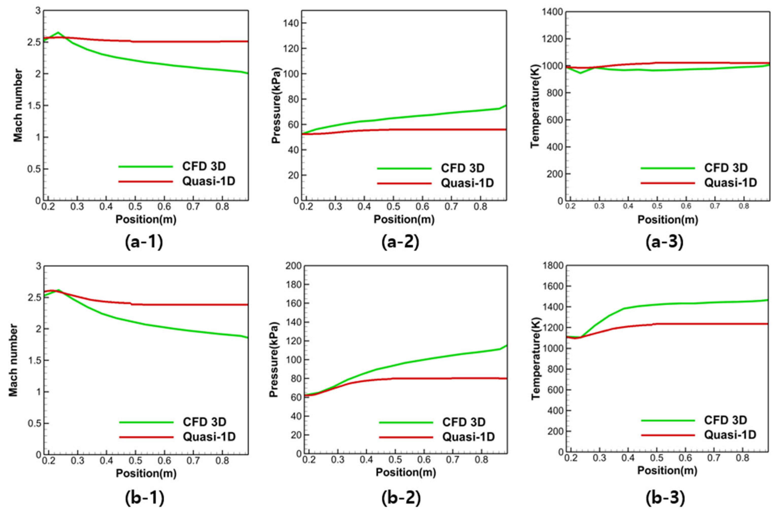
Figure 14 compares the quasi-1D predictions with the cross-section-averaged 3D CFD results for Case 2. Figure 14(a-1–a-3) correspond to the lower rocket chamber pressure (11 bar), whereas Figure 14(b-1–b-3) correspond to the higher rocket chamber pressure (50 bar).
Figure 14.
Comparison of quasi-1D predictions with cross-section-averaged 3D CFD results for Case 2 ( km). (a-1) Mach number at bar; (a-2) static pressure at bar; (a-3) static temperature at bar; (b-1) Mach number at bar; (b-2) static pressure at bar; (b-3) static temperature at bar.
From the standpoint of mode identification, Figure 12 indicates that thermal choking does not occur for either chamber pressure condition in Case 2, and the flow retains supersonic combustion characteristics throughout the engine. Consistently, the Mach number distributions in Figure 14(a-1,b-1) show that the quasi-1D analysis also predicts supersonic flow over the full streamwise extent for both cases, leading to the same ESJ mode classification. This consistency implies that the quasi-1D model captures the reduced tendency for thermal choking under high-Mach number inflow conditions.
To quantify the agreement level between the quasi-1D predictions and the cross-section-averaged 3D CFD results, the maximum deviations were evaluated for Mach number, static pressure, and static temperature. The corresponding maximum deviations were 32.35%, 32.09%, and 20.84%, respectively. This level of agreement is considered acceptable for the intended role of the present framework, namely to capture macroscopic streamwise behavior and thermal choking-based mode identification in a reduced-order manner.
6. Conclusions
This study developed a rapid quasi-1D reacting-flow analysis capability for rocket-based combined cycle engines intended for preliminary assessment across a broad flight envelope. The internal flow was modeled as steady and quasi-1D in a variable area duct by solving the coupled conservation equations together with species transport, and finite-rate chemical kinetics were included to account for combustion driven heat release and composition change.
A central feature of the present framework is that the quasi-1D mixing treatment is informed by an axial mixing efficiency distribution extracted from non-reacting 3D CFD for the same RBCC configuration, rather than being prescribed arbitrarily. In the present approach, the mixing efficiency is evaluated from the non-reacting 3D solution using a sectional definition based on the local equivalence ratio distribution, and the resulting streamwise mixing efficiency profile is then imposed as an input to the quasi-1D model to represent the progressive availability of reactable fuel along the engine. This coupling is directly aligned with the objective of focusing on macroscopic indicators relevant to RBCC mode assessment, including thermal choking behavior and the associated streamwise trends of flow properties.
A mode-dependent solution strategy was established by separating the computation into scramjet mode and ramjet mode procedures with a switching criterion based on whether a sonic condition occurs within the combustor. When a sonic point appears and the computation switches to the ramjet mode procedure, the combustor inlet condition is iteratively adjusted so that the predicted thermal choking location coincides with the geometric choking location, and pre-combustion shock trains in the isolator are treated within the ramjet mode procedure using the isolator model adopted in the present study.
The code was verified against published hydrogen-fueled scramjet quasi-1D results by reproducing the streamwise trends of key quantities including Mach number, pressure, temperature, and density.
The framework was then applied to an RBCC configuration under operating conditions representative of the ERJ and ESJ regimes, and the quasi-1D predictions were compared with cross-section-averaged results from 3D RANS CFD. The comparisons indicated consistent mode identification and comparable axial profiles at a level suitable for preliminary analysis, while retaining the practical advantage of substantially reduced computational cost relative to 3D simulations.
While the quasi-1D assumption necessarily limits representation of local 3D features, the present framework provides a practical reduced-order tool for rapidly examining operating condition effects and mode transition tendencies in RBCC engines, and it can support early-stage screening of design candidates and guide subsequent high-fidelity analyses.
Author Contributions
Conceptualization, S.H.K.; Methodology, S.H.K.; Software, J.J.P. and S.G.L.; Validation, S.G.L.; Investigation, J.J.P., S.G.L. and S.W.L.; Writing—original draft, J.J.P.; Writing—review & editing, S.H.K.; Visualization, J.J.P. and S.W.L.; Supervision, S.H.K.; Project administration, S.H.K. All authors have read and agreed to the published version of the manuscript.
Funding
This work was supported by Korea Research Institute for defense Technology planning and advancement (KRIT) grant funded by the Korea government (DAPA (Defense Acquisition Program Administration)) (No. KRIT-CT-22-030, Reusable Unmanned Space Vehicle Research Center, 2026).
Data Availability Statement
The original contributions presented in this study are included in the article. Further inquiries can be directed to the corresponding author.
Conflicts of Interest
The authors declare no conflict of interest.
References
- Munoz, A. Design of a Rocket-Based Combined Cycle Engine. Master’s Thesis, San Jose State University, San Jose, CA, USA, May 2011. [Google Scholar]
- Thomas, S.R.; Perkins, H.D.; Trefny, C.J. Evaluation of an Ejector Ramjet Based Propulsion System for Air-Breathing Hypersonic Flight; NASA-TM-107422; NASA Lewis Research Center: Cleveland, OH, USA, 1997.
- Trefny, C.J. An Air-Breathing Launch Vehicle Concept for Single-Stage-to-Orbit; NASA/TM-1999-209089; NASA Glenn Research Center: Cleveland, OH, USA, 1999. [CrossRef] [Scilit]
- Faulkner, R.F. Integrated System Test of an Airbreathing Rocket (ISTAR). In Proceedings of the 10th AIAA/NAL-NASDA-ISAS International Space Planes and Hypersonic Systems and Technologies Conference, Kyoto, Japan, 24–27 April 2001; AIAA Paper 2001-1812; AIAA: Reston, VA, USA, 2001. [Google Scholar] [CrossRef] [Scilit]
- Liu, Y.S.; Xue, R.; Liu, J.L.; Xu, C.Q.; Zhu, S.H.; Liu, B. Numerical Study on the Dynamic Process of Ramjet/Scramjet Mode Transition in the Integrated Full Flow Path for RBCC Engine. Appl. Therm. Eng. 2023, 231, 121017. [Google Scholar] [CrossRef] [Scilit]
- Torrez, S.; Scholten, N.; Micka, D.; Driscoll, J.; Bolender, M.; Doman, D.; Oppenheimer, M. A Scramjet Engine Model Including Effects of Precombustion Shocks and Dissociation. In Proceedings of the 44th AIAA/ASME/SAE/ASEE Joint Propulsion Conference and Exhibit, Hartford, CT, USA, 21–23 July 2008; AIAA Paper 2008-4619; AIAA: Reston, VA, USA, 2008. [Google Scholar] [CrossRef] [Scilit]
- O’Brien, T.F.; Starkey, R.P.; Lewis, M.J. Quasi-One-Dimensional High-Speed Engine Model with Finite-Rate Chemistry. J. Propuls. Power 2001, 17, 1366–1374. [Google Scholar] [CrossRef] [Scilit]
- Birzer, C.H.; Doolan, C.J. Quasi-One-Dimensional Model of Hydrogen-Fueled Scramjet Combustors. J. Propuls. Power 2009, 25, 1220–1225. [Google Scholar] [CrossRef] [Scilit]
- Nam, J.; Bae, G.; Kang, S.-H.; Yoh, J.J. Reduced-Order Modeling of the Dual-Mode Scramjet Combustor with Hydrogen and Kerosene Combustion. Int. J. Aeronaut. Space Sci. 2025, 26, 2433–2444. [Google Scholar] [CrossRef] [Scilit]
- Scheuermann, T.; Banica, M.; Chun, J.; von Wolfersdorf, J. Eindimensionale Untersuchungen zur Gestuften Brennstoffeinbringung in Einer Scramjet-Brennkammer. In Proceedings of the Deutscher Luft- und Raumfahrtkongress (DLRK 2008), Darmstadt, Germany, 23–25 September 2008. Paper DLRK2008-81208. [Google Scholar]
- Tourani, C. Computational Simulation of Scramjet Combustors—A Comparison between Quasi One-Dimensional and 2-D Numerical Simulations. In Proceedings of the 17th AIAA International Space Planes and Hypersonic Systems and Technologies Conference, San Francisco, CA, USA, 11–14 April 2011; AIAA Paper 2011-2285; AIAA: Reston, VA, USA, 2011. [Google Scholar] [CrossRef] [Scilit]
- Virtanen, P.; Gommers, R.; Oliphant, T.E.; Haberland, M.; Reddy, T.; Cournapeau, D.; Burovski, E.; Peterson, P.; Weckesser, W.; Bright, J.; et al. SciPy 1.0: Fundamental Algorithms for Scientific Computing in Python. Nat. Methods 2020, 17, 261–272. [Google Scholar] [CrossRef] [Scilit] [PubMed]
- Hairer, E.; Wanner, G. Stiff Differential Equations Solved by Radau Methods. J. Comput. Appl. Math. 1999, 111, 93–111. [Google Scholar] [CrossRef] [Scilit]
- McBride, B.J. NASA Glenn Coefficients for Calculating Thermodynamic Properties of Individual Species; NASA/TP-2002-211556; NASA Glenn Research Center: Cleveland, OH, USA, 2002.
- Lin, K.C.; Tam, C.J.; Jackson, K.R.; Eklund, D.R.; Jackson, T.A. Characterization of Shock Train Structures Inside Constant-Area Isolators of Model Scramjet Combustors. In Proceedings of the 44th AIAA Aerospace Sciences Meeting and Exhibit, Reno, NV, USA, 9–12 January 2006; AIAA Paper 2006-816; AIAA: Reston, VA, USA, 2016. [Google Scholar] [CrossRef] [Scilit]
- Shapiro, A.H. The Dynamics and Thermodynamics of Compressible Fluid Flow; Ronald Press: New York, NY, USA, 1953. [Google Scholar]
- Saxena, P.; Williams, F.A. Testing a Small Detailed Chemical-Kinetic Mechanism for the Combustion of Hydrogen and Carbon Monoxide. Combust. Flame 2006, 145, 316–323. [Google Scholar] [CrossRef] [Scilit]
- Jeong, S.; Kang, S.H. A Numerical Study on the Combustion Characteristics of RBCC Engines Based on Embedded Rocket Configurations. J. Korean Soc. Propuls. Eng. 2024, 28, 16–26. [Google Scholar] [CrossRef] [Scilit]
- Menter, F.R. Two-Equation Eddy-Viscosity Turbulence Models for Engineering Applications. AIAA J. 1994, 32, 1598–1605. [Google Scholar] [CrossRef] [Scilit]
- Huang, S.; Chen, Q.; Cheng, Y.; Xian, J.; Tai, Z. Supersonic Combustion Modeling and Simulation on General Platforms. Aerospace 2022, 9, 366. [Google Scholar] [CrossRef] [Scilit]
- ANSYS Inc. Ansys Fluent Theory Guide, Release 2023 R1; ANSYS Inc.: Canonsburg, PA, USA, 2023. [Google Scholar]
- Larsson, A.; Zettervall, N.; Hurtig, T.; Nilsson, E.J.K.; Ehn, A.; Petersson, P.; Aldén, M.; Larfeldt, J.; Fureby, C. Skeletal Methane–Air Reaction Mechanism for Large Eddy Simulation of Turbulent Microwave-Assisted Combustion. Energy Fuels 2017, 31, 1904–1926. [Google Scholar] [CrossRef] [Scilit]

Disclaimer/Publisher’s Note: The statements, opinions and data contained in all publications are solely those of the individual author(s) and contributor(s) and not of MDPI and/or the editor(s). MDPI and/or the editor(s) disclaim responsibility for any injury to people or property resulting from any ideas, methods, instructions or products referred to in the content. |
© 2026 by the authors. Licensee MDPI, Basel, Switzerland. This article is an open access article distributed under the terms and conditions of the Creative Commons Attribution (CC BY) license.