


Abstract
The engine system requirements for different engine cycles significantly influence the design of the mixing head. A literature review of fuel-injection technology for hydrogen and methane is presented. The literature review aimed to answer proposed questions specific to the liquid rocket engine fuel injector design. The current review methodology accounts for the engine system effect. Thus, a comprehensive literature review of the working principles of startup-staged-combustion-cycle engines based on original patents is provided. At the end of the review, the research gaps and suggestions for further work are summarised. At high mass flow rate and injection pressure in the supercritical regime (>50 MPa), experience is limited to the staged-combustion cycle developed in Russia and the US. It is necessary to consider a fluid-dynamic heat transfer coupling study for the multi-injection element design in the supercritical state. Cryogenic spray atomisation experiments need to be designed with research significance in mind. It is still needed to study how the similarity of the spray flow field to the combustion performance affects a liquid rocket engine problem. Moreover, scaling stoichiometric mixing theory needs to be expanded to different injector types, such as tricoaxial and pintle injectors, to validate the correlation between the non-reactive mixing length and flame length.
1. Introduction
Kang et al. [1] reviewed primary atomisation and secondary atomisation characteristics for pressure swirl injectors. The review focused on the influence of the operating environment, including ambient pressure and temperature. Zhao et al. [2] conducted a literature review study on the spray atomisation characteristics of pintle injectors. Macroscopic spray characteristics and semi-empirical equations related to the spray cone angle correlated to the momentum flux ratio and injector geometry ratio are included. The review was primarily focused on non-reacting spray. Vijay et al. [3] conducted a literature review of the pressure swirl atomiser, followed by an examination of its internal and external flow characteristics. The review study focused on the effect of injection pressure on internal flow, particularly on film-formation and breakup modes influenced by external flow characteristics. Semi-empirical equations on spray morphology, Sauter Mean diameter, and spray breakup length were summarised. Zhao et al. [4] comprehensively reviewed active control approaches to mitigate the occurrence of combustion instabilities in the lean combustion system applied for land gas turbine engines. The review studied feedback, adaptive, model-based, and sliding-control methods.
Gugulothu [5] conducted a systematic literature review of the State-of-the-Art fuel-injection technology for a scramjet engine. Strut injector and mixed strut-and-plyon injection techniques were identified as critically important for fuel-air mixing. The influence of operating conditions, Mach number, stagnation pressure, Reynolds number, and equivalent ratio was suggested to be insufficiently addressed and requires focus. Ren et al. [6] conducted a literature review of fuel spray challenges in supersonic combustion technology for scramjet engines. The review focused on the liquid jet atomisation characteristic in the supersonic crossflow, with emphasis on mixing, stability, and the interaction mechanism between the shock wave and combustion.
Paolo Baiocco [7] provided a literature review of high-energy and low-energy reusable launch systems, summarising the relevant advantages and challenges. Byerk et al. [8] reviewed State-of-the-Art retropropulsion systems based on the influence of external aerodynamic flow characteristics. The review study indicated that generating aerodynamic and aerothermal databases remains a challenge due to the lack of flight tests and aerodynamic experiments. Sergio Roca et al. [9] reviewed PID and other automatic control methods applied to liquid rocket engines. Improving the control technique used for reusable launch vehicles and extending the throttling range below 30% were suggested for consideration. Shraddha C.P. Priyadarshi et al. [10] provided a comprehensive review of the evolution of recovery methods used and in use for launch vehicle systems. The study provided a review of the recovery technique classification as follows. Level of energy dissipation, method of energy dissipation, landing site, extent of recovery, and level of autonomy. Fu et al. [11] reviewed past and current research on pulsating dynamic spray characteristics. The review identified research gaps due to a lack of focus on pulsating spray atomization, and klystron effects have not been well-investigated. Moreover, there is less work on the development of dynamic injector models at supercritical injection conditions. Table 1 summarises the previous review methodology and research limitations.
Table 1.
Summary of the existing literature review closely related to injector technology and aerospace flight vehicle technology relevant to rockets.
Using methane has an advantage in cost compared to hydrogen and kerosene. It is feasible to adopt an intermediate common tank, as methane and liquid oxygen have similar boiling temperatures at standard atmospheric conditions. Enable a self-pressuring tank, heated methane recirculates back to the tank and can be used as pressurised fluid [12]. The methane rocket has a higher density impulse than hydrogen and a higher impulse-to-weight ratio than kerosene. A high threshold wall temperature is compatible with a regenerative cooling engine in a high-pressure system. Compatible with partially reusable launch vehicles and expendable launch vehicles [13]. Referenceable and manageable standards with relevant specifications have been developed for methane [14]. Thus, this review paper primarily focuses on cryogenic propellant.
2. Methodology
Based on the background of the launch vehicle complex system, which is mainly composed of control, measurement, power, and health-monitoring systems. The assumption is made by neglecting power distribution, telemetry, and communication avionics systems, as they are not directly related to the mixing head design at the component level. After simplification, the functional system is directly related to the control system (GNC), which can assist in the conceptual and preliminary design of the launch vehicle and the synthesis of performance analysis. Control systems in the PID and H infinity method were reviewed in [9], which is not directly related to the fuel injector design. Thus, reviewing past and current guidance laws can provide insight into the engine-throttling requirements for fuel injector development, which is the scope of the first question. To address the lack of knowledge on full-scale injector requirements, this review paper will include engine system information as part of its second scope. The review will not focus on empirical correlations in fuel spray atomisation. Moreover, it differs significantly from the previous review paper on liquid-propellant injection elements.
The overall methodology does not require predetermined questions but still necessitates using engine system information to adjust the paper selection criteria until suitable questions are specified, as shown in Figure 1. The specified questions can cover the missing research elements from the past review paper. Thus, a literature review is needed to further the understanding of fuel injector technology for liquid rocket engines.
Figure 1.
The overall literature review of the methodology. Dotted arrow-Scope of questions are not relevant to the research papers selection.
To bridge the missing review gaps from the previous review paper. The current aim of the review is to answer the proposed questions as stated in Table 2. What are the design constraints that influence the conceptual/preliminary fuel injector design related to the propellant mixing and combustion? What are the current State-of-the-Art propellant injection techniques applied to the closed-cycle engines? What are the methods used in the research and development process of propellant injection elements?
Table 2.
Summary of review questions and paper selection criteria.
Derived method from using the guidance law based on the flight dynamic equation to prepare the literature review. The literature review primarily focused on the staged-combustion-cycle engine. There is a design requirement to develop engine components, including propellant injection elements. The current ORSC engines developed by Russia and China mainly use kerosene and liquid oxygen, and there are few journal papers on methane/liquid oxygen. The scope of the paper selection needs to be adjusted. The gas-generator-cycle engine, which uses cryogenic propellant from the European Space Launch Vehicle, will be considered.
The guidance system provides all launch vehicle performance information specific to the first and upper stages. The guidance algorithm relies on solving the nonlinear flight dynamics equation, which is also used for trajectory analysis during the preliminary design stage. The liquid rocket engine needs to fulfil combustion stability requirements for the entire rocket flight phase, including thrust losses due to throttling at maximum dynamic pressure and during the gravity turn phase. Thus, including guidance and engine system content will add knowledge to better understand the design of propellant injection elements, as they are designed and tested to meet flight performance requirements rather than optimised individually. Further explanation of the needs of each system is provided in the introduction paragraph for each section.
3. Launch Vehicle Guidance System
3.1. Introduction of the State of Development of the Guidance System
Space launch vehicles are autonomous flight vehicles and face design constraints different from those of aircraft and autonomous road vehicles. Space launch vehicles face greater environmental uncertainty due to their short residence time at low altitude, non-fixed mission routes, and inadequate database support. Environmental uncertainties are typically generated by significant differences in flight speed, aerothermodynamic challenges, and the non-fixed descent trajectory phase of a partially reusable launch vehicle system [15]. Open-loop derived algorithms and closed-loop algorithms are primarily used in guidance law for a space launch vehicle system. An open-loop algorithm involves pre-mission nominal trajectory planning and real-time correction; it is also called the perturbation guidance law. A closed-loop guidance algorithm does not rely on pre-mission trajectory planning and uses real-time trajectory planning [16]. The second-stage/upper-stage launch vehicle system is often neglected due to its aerodynamic influence and its flight approach to zero angle of attack. A closed-loop guidance law is commonly used for the second-stage launch vehicle, while the first stage uses the perturbation guidance law.
Ping Lu [17] clarified the terms and definition for the guidance and control system after interviewing 10 GNC experts from NASA and academia. Ping suggested that the academic definition of guidance is stated as follows:
“Guidance is about the determination of the maneuvering commands to steer the vehicle to fly a trajectory that satisfies the specified terminal/targeting condition as well as other pertinent constraints, and, if required, optimizes a defined performance.”
Control is the process of determining the applied forces and torques, or the actions of the control effectors, required to maintain stability and achieve the specified body attitude or flight condition of the vehicle. The guidance system provides an input command to the control system, which then sends an execution command to the actuator device. Thus, stability is not a requirement for the guidance system, but it is for the control system [17]. Details on the specific type of guidance system used for past and existing space launch vehicle systems can be found in Table 3.
Terminal-state control at engine shutdown is the fundamental working principle of the perturbation guidance method. Perturbation guidance uses the real velocity state, real flight position, and real flight time as input variables, all acquired from the onboard navigation system. Minimising dispersion caused by stage separation is indispensable for a multistage expendable/partially reusable launch vehicle to meet payload injection accuracy and precision requirements [18]. The perturbation guidance law is simplified to focus on minimising both flight-range and transverse-range deviations, as shown in Equation (1), while also minimising deviations in engine shutdown time [18]. Perturbation guidance uses a control launch vehicle flight state within the acceptable deviation range of the offline trajectory, rather than relying solely on tracking the offline trajectory. An explicit perturbation guidance method is commonly used for the first stage, such as Angara, Soyuz-5, and Amur [19]. Equations (2)–(4) are designed for terminal control of the final state of the first stage. The O/F ratio variation needs to be precisely controlled within specified percentages, as large O/F deviations will increase engine design challenge from change of combustion flame temperature. Alternatively, the control system, along with propellant injection elements, also contributes to how propellant is consumed and distributed, thereby influencing the distribution of the O/F ratio.
The iterative guidance mode does not require a full loading of a pre-determined trajectory onboard. Generating a trajectory onboard during flight is a key characteristic and a type of trajectory adaptation method. IGM uses real-time, instantaneous input parameters, including velocity, position, and longitudinal acceleration relative to the final state, generated by the navigation system. Similar to the perturbation-guidance method, the formulated method uses flight terminal-state variables as terminal constraints. Because the IGM neglected aerodynamic effects, the method was widely adopted by upper-stage launch vehicles. The main engine cutoff condition is selected as a terminal state variable [20]. The Iterative guidance method employs optimal control theory to find the optimum attitude angle for generating control commands. PEG, a guidance algorithm, uses Hamiltonian optimisation to solve the time-orbit injection solution. The existing optimisation problem is to minimise the orbit injection time under the flat-Earth assumption, assuming uniform gravity along the maximum-thrust arc [21]. Unlike a complete numerical trajectory algorithm, powered explicit guidance is a semi-analytical corrector that does not require tracking or preloaded trajectories. PEG requires the use of terminal-state variables, preloaded burn time, and mass flow rate to establish the initial mass time constant in real flight. The engine shutdown condition needs to meet the criteria as = [21]. Powered explicit guidance is a reliable guidance algorithm that has been used by NASA launch vehicles (Upper stages) for more than 30 years since the Space Shuttle programme.
Lu proposed a closed-loop guidance method to overcome the limitations of specific-stage launch vehicles, using PEG and IGM while accounting for aerodynamic and engine throttling. It is also a Hamiltonian optimal control-based guidance algorithm for different objective functions, designed to minimise propellant usage. Developed guidance is an onboard guidance algorithm that does not use offline trajectory data [22]. Formulate guidance is proposed as a function of time, with constraints related to dynamic pressure, as shown in Equation (5) and the constraint equation. The engine throttling parameter of ηmin must be greater than zero during all powered flight phases. When the dynamic pressure is less than and equal to the maximum dynamic pressure, the throttle parameter can be computed from Equation (8), and the corresponding constraint conditions can be found from Equation (9). Equation (7) is applicable only when the thrust is throttled back to its maximum by using Hamiltonian optimisation with the aerodynamic drag force. The proposed closed-loop guidance was compared with the open-loop guidance algorithm and found to be feasible and accurate. Lu later studied the numerical assessment of the closed-loop guidance application on Ares 1 and preliminarily concluded that it is a feasible guidance method [23].
Table 3.
Summary of the guidance algorithm in use/used for existing launch vehicles.
3.2. Dynamic Load Reduction by Using Engine Gimbaling
The powered active ascent phase refers to the time from engine start to engine shutdown. Pitch programmes start, gimbal deflective angle without other control surfaces. The axial engine installation thrust offset from the symmetrical body will cause altitude thrust losses. The engine needs to maintain combustion stability throughout the entire active powered ascent phase under full-thrust and thrust-throttle conditions. The combustion stability question will return to the design of propellant injection elements and will include the effects of mixture ratio control and momentum flux ratio. The powered active ascent phase also determines the fuel injector design requirements based on the propellant flow rate.
When a liquid rocket engine is not designed for throttling capability and deep thrust throttling, passive and active load-relief methods are used and rely on transient manoeuvres. The first option involves designing the mean wind profile and setting flight-environment constraints until the winds are acceptable, similar to the second option. The third option involved a wind-bias trajectory, using a statistical daily wind and wind-load relief method. In terms of practical implementation, the main advantages of the first two options come at the cost of restricting launch vehicle availability and launch frequency under the second option, which employs a robust launch vehicle structure design with aeroelastic coupling. The wind bias trajectory is one of the methods in use, but it requires an actual wind field database and extensive testing for verification. Active load relief employs real-time correction instead of premeasurement for high-altitude steady wind speed and shear wind [31].
Mingchao He et al. [32] developed an active load relief control model by adjusting the rolling channel to align the lateral surface with the direction of the most substantial wind interference. To prevent excessive maximum axial load, a decrease in flight velocity reduces thrust by changing the effective deflective angle of the engine. The maximum limit of the effective deflective angle depends on the engine gimbaling technique. In this subsection, the working mechanism of an engine-gimbaling technology alternative to thrust vectoring for high-thrust, high-pressure liquid rocket engines is outlined.
There are two engine-gimbaling techniques applied for high-pressure staged-combustion-cycle engines. Pump front swing gimbaling and pump rear swing gimbaling. The liquid rocket engines use pump-front swing gimbaling, which means the entire engine swings about a single axis [33]. The current examples of staged-combustion engines with thrust greater than 1100 kN are the early YF-100, YF-90, and the Raptor. Pump rear gimbaling only swings the main thrust chamber units, which are connected to the flexible bellow section about a datum axis. Fuel bellows compensators are positioned after the fuel pump. The other rigid structure units—the turbopump and the rigid part of the gas exhaust line—remain stationary and well-applied on RD-171, 180, 191, and also for YF-130 [33]. Pump rear gimbaling required a flexible metallic fuel line instead of a whole-engine swing, but this will increase structural design challenges in the high-pressure, hot-exhaust-gas operating environment at the bypass section [34].
3.3. Maximum Dynamic Pressure Derived Throttling Requirement
The space launch vehicle operates in coupled structural, acoustic, and shock environments and experiences maximum vehicle load during the endo-atmosphere ascent phase [35]. Lift-off, maximum dynamic pressure, engine power cutoff, and stage separation are considered critical events due to their influence on the accuracy of final payload insertion. Michael introduced a workflow for the inaugural flight-test process for the Delta IV from Boeing’s perspective [35]. During the first MECO, smooth engine throttling from full power to minimum is critical to mitigate vehicle load oscillation. The low-frequency response of the load also needs to fall within the prediction margin to deliver the payload with acceptable accuracy [35].
RD-180 is an ORSC engine used with RP-1/LOX, which has flight experience on Atlas III and Atlas V. Figure 2 shows an example of flight mission throttling requirements for Atlas III and Atlas V, with engine thrust transitioning to the maximum condition in a few seconds at startup [36]. The thrust must be reduced to 65% (Atlas III) just before reaching maximum dynamic pressure during transonic flight, then throttled back to 87% after flight phase of occurance of maximum dynamic pressure [36]. To avoid exceeding the design constraint, thrust is throttled back to 47% to maintain flight acceleration within tolerance. During engine throttling, the main turbopump rotation speed decreases as thrust decreases, thereby reducing the turbine outlet temperature [36].
Figure 2.
Thrust throttling profile for RD-180. Reproduced from Ref. [36].
4. The Working Principle of Staged-Combustion-Cycle Engines with Single-Thrust Chambers
Bulk et al. [37] pioneered an integrated pre-burner combustion for a methane/liquid oxygen staged-combustion-cycle engine, as shown in Figure 3. The integrated combustor structure can be manufactured as a single part using additive manufacturing. The patent research used a fuel-rich gas generator for a full cryogenic propellant combination, with the fuel-rich exhaust gases driving the turbine. Methane is injected into the gas generator and main thrust chamber from the regenerative cooling channel (11). The fuel flow rate after the fuel pump is regulated by using valve (4) [37]. The fuel flow moves upstream, and a portion of the fuel is split. The first portion of fuel is injected into the annular injector head (17), and the rest of the fuel flows into the injector head of the main thrust chamber (22) [37]. The oxidiser flow is divided into the three streams: supply pipeline (12), supply pipeline (14), and supply pipeline (16). Oxidiser is routed from the supply pipeline (12) to the cooling manifold (13), and oxidiser within the cooling cavity is used as coolant for the gas generator (18). Oxidiser within the cooling cavity (13) will be gasified. Oxidiser is directly routed to the injector head of the main thrust chamber via the supply pipeline (16) and remains in a liquid state [37]. The gasified oxidiser flows from the cooling manifold (13) and is injected into the gas generator. Compared with the first two oxidiser streams, a small amount of oxidiser is supplied to the cooling manifold (15) near the nozzle throat [37]. These small portions of oxidiser are used as a coolant for transpiration or film cooling purposes. The engine system configuration uses a multiple-bypass regulator with adjustable fuel and oxidiser. The patent claimed that the turbine inlet temperature can be increased up to 1300 K by using rich methane combustion with oxidiser regenerative cooling [37].
Figure 3.
A staged-combustion-cycle engine with the concept of an integrated pre-burner. Reproduced from US Patent No. 2022.0205411A1 in Ref. [37].
Katorgin et al. [38] outlined the pioneering work of developing the method and installing the thrust throttle device on a single-pre-burner staged-combustion-cycle engine, with a generic application. The engine system used a pneumatic-hydraulic start circuit, also known as the self-start technique. Figure 4 illustrates the working principle of the self-starting and throttling method. The engine is started using a start tank (47). High-pressure fuel from the start tank is discharged, and hydraulic fuel pressure can rupture the ampoule membrane to release igniter fuel; triethylaluminium is used [38]. At the same time as the start, starting/cut-off valves (12, 37, 25) receive an electrical signal and switch to the open position. As the igniter fuel produces hypergolic combustion, the engine system is designed without an ignition system [38]. Both hypergolic fuels enter the gas generator and the main thrust chamber, and the turbine also starts rotating. The igniter fuel is delayed from entering the main thrust chamber after the gas generator starts generating hot gases [38]. Then, the starter tank is cut off when turbopump pressure reaches the nominal design condition. The patent research introduced an onboard heat exchanger (44) to rapidly cool down a small portion of hot gases after the engine started [38]. The cooled working fluid is used to drive the oxidiser boost turbine and is remixed into the pipeline. At the same time, the boost fuel turbine is driven by a small portion of fuel discharged from the first-stage fuel pump [38].
Figure 4.
Systematic diagram of a staged-combustion-cycle engine. (12)-Oxidiser valve; (25)-Fuel valve for main thrust chamber; (37)-Valve; (44)-Heat exchager; (49)-Start tank. Reproduced from US Patent No. 6226980B1 in Ref. [38].
Gubanov David Anatolyevich et al. [39] proposed a closed-cycle engine design with dual pre-burners, without using boost turbopump units. The engine system architecture is designed with two-stage fuel pumps, two-stage oxidiser pumps, and two independent turbine units. Two independent turbines are driven by the exhaust gases generated from fuel-rich and oxidiser-rich gas generators [39]. The engine design uses autogenous pressurisation tanks and heat exchangers to heat a small portion of fuel and oxidiser. About 90% of the fuel is fed into dual pre-burners, and 4% of the fuel flow is discharged into the combustor at the nozzle’s exit critical section (near the throat region) [39]. 90% of the oxidiser is fed to the dual pre-burners at the specified flow rate. About 7–10% of the oxidiser is fed into the main thrust chamber, and the rest enters the heat exchanger. The patent research preliminary assessment found that the main thrust chamber can reach 30 MPa, with a working principle similar to the full-flow staged-combustion cycle and an alternative performance design to the RS-25 [39].
5. Startup Method for a Staged-Combustion-Cycle Engine
To resolve technical startup problems, a staged startup method is needed and developed for high-pressure staged-combustion engines. Staged startup refers to a smooth transition to full thrust from a distinguished, controllable, pre-planned operational condition. Pre-design operating is also called the initial operation condition. The staged startup is already well-established for staged-combustion-cycle engines. The engine startup sequence during initial operating conditions must meet the diagnostic time requirements of the engine health monitoring system. Nominal design points are selected between 60% and 65% of the full thrust level from CASC’s perspective [40]. Modernised staged-combustion-cycle engines use electromechanical actuators to precisely control the mixture ratio, such as the RD-0120, YF-100/115/130, offering improved controllability and reliability. In contrast, the early versions of RD-170, RD-180, RD-191, and RS25 used a hydromechanical control system [40].
Borisovich et al. [41] developed a startup method using external compressed gas for a closed-cycle engine with conjoined combustors. The pre-burner is coaxially integrated with the main thrust chamber, and both combustors are equipped with an electric ignitor, as shown in Figure 5. Electrical signals are sent from the control unit (43) to the thrust regulator (32) when the engine is started. The ground cylinder tank (40) supplies compressed gas; it enters the starting pipeline (35) to start the turbopump (2) [41]. When the turbopump is started, the fuel pump, oxidiser pump, and an auxiliary fuel pump unit (6) also start increasing pressure. Fuel valves (20, 25, 27) receive an opening command from the control unit (43) [41]. The engine system design also adopted all liquid oxygen fed into the gas generator. A portion of the fuel enters the gas generator through a regenerative cooling conduit, while the remainder enters the main thrust chamber through the regenerative cooling channel via fuel valve (20) [41]. The outlet of the fuel valve (20) is designed to connect to the fuel manifold, while its inlet is connected to the pipeline via the fuel pump (4). After a launch vehicle lifts off the ground, the ground connection is disconnected, the check valve (38) closes, and the onboard valve (36) opens upon receiving an electrical signal [41]. Compressed air (37) is used and enters the turbine (5) through the thrust regulator (32). Thus, the main engine thrust is primarily throttled by a thrust regulator (32) to adjust turbine rotational speed. The patent research claimed the engine architecture also has a good compatibility with helium purge to minimise residual fuel after receiving the engine shut-down signal [41].
Figure 5.
A staged-combustion-cycle engine designed with the concept of integrated combustors and external high-pressure gaseous startup. Reproduced from RU Patent No. 2299345C1 in Ref. [41].
Nanni Gong et al. [42] proposed a low-power-consumption, half-self-starting method for high-thrust, full-flow staged-combustion-cycle engines to address poor start quality. The fuel and oxidiser pipelines are primed, and the turbines are started using high-pressure gases from the external gas bottle. When the engine inlet pressure exceeds the critical cavitation pressure, and the turbopump operates at a positive hydraulic head, the oxygen and fuel valves of the gas generator are opened in a specific time sequence [42]. Then, the engine transitions to self-starting. A simplified diagram of the layout of separation turbine units for a full-flow staged-combustion-cycle engine, which can reduce startup power requirements, is shown in [42]. Thus, it further reduces propellant consumption during engine start. The patent research claimed that starting each turbine requires only 5% of the nominal turbine power. The ignition sequence of the gas generators depends on the calculation and the transient characteristic of the turbopump power.
Chvano V.K et al. [43] described the challenges of rapid and delayed startup responses in a high-pressure staged-combustion engine. A sharp pressure peak in the chamber can increase back pressure on the turbine, raising the turbopump speed. Additionally, a temperature surge may occur due to increased fuel flow in the gas generator and burnout, which affects the turbine. The delayed startup response can reduce turbopump speed and lead to unexpected engine ignition [43]. Their patent proposed simplifying the engine’s pneumatic-hydraulic circuit to ensure reliable starting while reducing costs and weight for closed-cycle engines. The patent research introduced a startup method that uses a hydraulic turbine, which a single-pre-burner version of the staged-combustion-cycle engines can effectively adopt [43]. The working principle of a self-startup and thrust throttle plan is depicted in Figure 6. The patent research outlined additional details on the starter tank (4). Fuel within the starter tank will be pressurised by the high-pressure gas supplied by the gas bottle (47). The additional description of the starter tank units corresponding to the control valves is provided. After engine startup, the second stage of the fuel pump (23) outlet pressure increases to the nominal, the hydraulic relay (63) is activated, and the fuel from the starting tank enters the above piston cavity (70) of the hydraulic drive (62) and the cavitating jet (69) through the line (67) [43]. Then, the starting tank stops fuel supply when the oxidiser pump outlet pressure reaches a certain level, and valve (46) automatically closes. The oxidiser boost pump turbine unit then switches to being driven by the oxidiser rich gas divided from the turbine [43].
Figure 6.
Self-startup concept with pneumatic-hydraulic circuit. Reproduced from RU Patent No. 2232915C2 in Ref. [43].
6. Staged-Combustion-Cycle Engines with Multiple-Thrust Chambers
Sergeevich et al. [44] introduced the concept of two independent turbines driven by a common stream of hot gases rather than a single turbine unit. This concept is feasible for the RD-171M. The patent research aimed to reduce the dynamic load in a single turbine unit and increase thrust. The preliminary analysis by Sergeevich indicated the adoption of a two-turbine unit separation that can increase thrust by 25% and reduce turbopump power by 25–40%. The engine cycle configuration is somewhat similar to the full-flow staged-combustion cycle. However, the working principle of all the oxygen fed into the dual-pre-burners remains the same as in the RD-180 and RD-191 [44].
Fuel is throttled into a portion and enters the main thrust chambers through the regenerative cooling channel. It has remained a staged-combustion-cycle engine with four main thrust chambers. The throttling scheme of this conjoined engine is notated in Figure 7. A centrifugal fuel pump (8) and a centrifugal oxidiser pump (9) are coaxially mounted on a single shaft driven by the gas turbine (17) [44]. The main fuel pump is designed with a two-stage configuration that comprises stage 1 (12) and stage 2 (13). The oxidiser pump (11) and the two-stage fuel pumps (12, 13) are coaxially mounted on a single shaft driven by the gas turbine (14). Initially, fuel throttling can be performed by the throttle valve (23) [44]. The divided portion of fuel enters the second-stage fuel pump, and the proposed regulator (29) can throttle the flow rate entering the pre-burner before it reaches the start/shutdown valves (31, 32). Fuel flow entering the thrust chambers is primarily regulated by the startup/shutoff valve (25), which is a conjoined valve for multiple main thrust chambers [44]. The patent research did not introduce any oxidiser flow rate regulation devices, and oxidiser flow rate variation is controlled by the gas turbines (14) and (17). The stability of the mixture ratio mainly depends on the fuel throttle unit (23) [44].
Figure 7.
Staged-combustion cycle system concept for RD-171M. (1, 1’)-Main thrust chamber; (2, 2’)-Cooling tract of the main thrust chambers; (3, 3’)-Mixing head for main thrust chambers; (4, 5)-turbopump units; (6, 7)-Pre burners; (10, 14)-Turbine; (15, 16)-Pipeline; (17, 18)-Manifold of turbines; (19, 20)-Turbine exhaust gases duct; (21)-Gas duct, (24, 26, 27)-Pipelines; (28)-Pipeline; (29)-Regulator; (30)-Branched Pipeline; (34, 35)-Start-up/Cutoff valves; (36)-Booster pre pump; (37)-Pipeline; (38)-Fuel booster pre pump; (39)-Pipeline; (40)-Gas turbine; (41, 43)-Pipeline; (42)-Hydraulic turbine. Reproduced from RU Patent No. 2520771C1 in Ref. [44].
Fedorovich [45] briefly introduced a throttle scheme to address the soft landing problem of a reusable launch vehicle. This scheme can also be adopted for high-pressure, staged-combustion-cycle engines. The patent research introduced two structural circuits that enable a deep throttle range of 20% to 100% [45]. A primary structure circuit and an additional structure circuit are installed in the pipelines. The main structure circuit operates during the ascent flight phase, while additional circuits connect to the combustion chamber to reduce thrust in the landing phase.
7. Throttling Methods
The flow regulator is installed after the outlet of the second-stage fuel pump, and the throttle valve is installed close to the inlet cooling channel of the main thrust chamber in YF-100. The simplified schematic diagram of the flow regulator is shown in Figure 8. It primarily controls the flow rate and stabilises pulsed fuel flow before it enters the pre-burner across a wide range of inlet pressure conditions. Fuel flow rate throttling is achieved by regulating the angle of the rotating shaft [46].
Figure 8.
Diagram of propellant regulator plan from YF-100 Labelled red box-throttle valves. Reproduced from Ref. [46].
Yong Hua et al. [46] introduced several thrust throttling methods and conducted a preliminary evaluation of their application in oxidiser-rich staged-combustion-cycle engines. Three approaches can achieve thrust throttle: throttle the fuel flow branch to the pre-burner, throttle the oxidiser flow branch to the pre-burner, or throttle the fuel flow branch to the main thrust chamber [46]. Moreover, it is still possible to throttle the turbine inlet gases using a flow divider and to reduce thrust to 86.37% on its own. Based on the original working principle of the ORSC engine, the pre-burner has a high oxidiser flow rate and a low fuel flow rate, with a high proportion of the fuel flow fed to the main thrust chamber [46]. The regenerative cooling requirement of the main thrust chamber primarily influences the predominant portion of the fuel flow rate. Throttling by changing the fuel flow rate entering the pre-burner increases the mixture ratio, thereby deviating from its nominal condition. However, the low end of the throttling range will be limited by combustion instability triggered by excess oxygen [46]. Only relying on simple fuel flow rate throttling cannot meet deep or wide-range throttling requirements below 50%. A low turbine inlet temperature limit for the YF-100 was found to be 420 K, and the engine thrust was throttled to 49.78% using the fuel flow throttle [46]. Combustion instability occurred at a low injector pressure drop, with a limit of 0.3 MPa. Vice versa, the oxidiser throttling method increases turbine inlet temperature and the upper temperature limit of the exhaust pipe duct [46]. The oxidiser pump will also be adjusted to its nominal condition and operated under off-design conditions, resulting in a decrease in the overall pressure of the turbopump system and increasing the risk of cavitation. It has been found that the throttle capability was limited to 89%.
In-service closed-cycle engines developed in China have a throttling capability range of 66–100%. It is unable to meet the minimum deep throttling requirement, even at 20% or lower, for a landing mission of a partially reusable launch vehicle. Chun Hong et al. [47] pioneered a deep-thrust-adjusting method for the staged-combustion-cycle engine, which can be implemented without substantial changes to the propulsion system, as shown in Figure 9 [47]. When thrust needs to be reduced from 100% to 20% power level, a gas diverter valve (1) will be opened to divert a portion of the hot exhaust gases, while the remaining exhaust gases drive the main turbine. Propellant pump power decreases as turbine power declines. The propellant mixture ratio needs to be regulated within the margin, and large deviations are prevented by adjusting the fuel throttle valve [47]. As the thrust needs to be further reduced to 10%, the main fuel valve (5) is closed. The flow rate needs to be further reduced by adjusting the gas diverter valve, and the mixture ratio of the main thrust chamber is stabilised via the fuel throttle valve [47]. The patent research claimed that the thrust throttling scheme applies to methane/liquid oxygen and kerosene/liquid oxygen engines [47].
Figure 9.
Deep throttling concept for a staged-combustion-cycle engine. (1)-Gas diverter valve; (2)-Fuel valve of main thrust chamber; (5)-Main fuel valve; (6)-Oxidiser valve; (7)-Fuel valve of pre burner; (8)-Low pressure fuel pump; (9)-High pressure fuel pump; (10)-Nozzle; (11)-Oxidiser pump; (12)-Pre burner; (13)-Turbine. Reproduced from CN Patent No. 108953003 in Ref. [47].
Barashkov Ivan Sergeevich et al. [48] introduced a method that uses a bypass line to regulate the mixture ratio for a staged combustion, as shown in Figure 10. The fuel and oxidiser flow rates are reduced by routing a small portion of the after-pump mass flow rate to the boost pump via a bypass line, while valves (6) and (11) are closed. To increase the oxidiser-to-fuel component ratio, valves (6) and (11) are opened to provide flow to the bypass line. The patent claims that the engine designed with this layout can meet the propellant ratio regulation requirement within ±3% to ±7% [48].
Figure 10.
Mixture ratio throttling by using a bypass line. (1)-Oxidiser pump inlet; (2)-Fuel pump inlet; (3)-Pre pump unit; (4)-Oxidiser pump outlet; (5)-By pass line; (6)-Oxidiser valves; (7)-Pre pump unit; (8)-First stage of fuel pump; (9)-Fuel transport pipe; (10)-Second stage of fuel pump; (11)-Bypass line closed valve. Reproduced from RU Patent No. 2836201C1 in Ref. [48].
8. Injector Design Requirements from the Engine System
The first and second points directly influence the design of the fuel injector. Nominal design-point selection directly influences the total flow rate and the engine system pressure requirements. At engine startup, the health monitor system must properly diagnose the engine components during the final countdown period, then generate a command for engine ignition and lift-off from the launch pad. When an engine system malfunction is detected, the engine diagnostic system will terminate the startup command [49]. The design redundancy from the engine fault analysis can determine the upper limit of the operating condition if the engine’s thrust redundancy is included.
Current staged-combustion-cycle engines are not designed to operate over a wide range of mixture ratios in actual flight conditions, based on engine steady-state test results [50]. A large O/F ratio deviation can cause significant shifts in combustion temperature and influence engine performance. The O/F ratio needs to remain constant during thrust throttling, when propellant flows into the propellant regulator units and flow stabiliser units are also required [51].
The challenges of providing adequate pressure drop across the pre-burner and main thrust chamber at low throttling conditions are significant. Moreover, due to the deep throttling requirement of a reusable launch vehicle, the minimum throttling range is even below 40% and down to 20%, which will lead to significant pressure changes in the turbopump and flow regulator. That further complicates the determination of the combustion stability boundary and injector design. The summary of the relevant research states that the development of staged-combustion-cycle engines is presented in Table 4, and the influence of the engine system on the fuel injector design is summarised as follows:
Table 4.
Summary of the patent and relevant research state.
- Nominal operation condition
- Upper limit operation condition
- Low limit operation condition
- Engine performance limitation requirement (Reliability tests)
9. Mass Flow Rate Characteristics
In the guidance section, terminate the state constraint for a first-stage launch vehicle by using O/F and propellant consumption as constraints to determine whether the engine shutdown criteria are satisfied. To fulfil the requirement, onboard propellant flow rate measurement and feedback become important, as large propellant fluctuations induced by two-phase flow can influence the control system feedback. The working principle of the gas generator cycle differs from that of a staged-combustion-cycle engine, using the high-temperature exhaust gases from the previous section. The main thrust chamber burns a greater portion of the propellant discharged from the pump. However, high-temperature oxidiser-rich exhaust gases are combusted again in the main thrust chamber of a staged-combustion cycle. The different working principles of the engine system lead to different flow rate characteristics for design propellant injectors. The propellant injection element design for a staged-combustion-cycle engine will further lead to high-pressure incompressible flow, high-temperature compressible flow, and two-phase flow problems. There is a similarity between kerosene/liquid oxygen injection and hydrogen/liquid oxygen or methane/liquid oxygen injection systems, as they all use inert gases. For storable propellant cases like kerosene/liquid oxygen injection, this will lead to injection problems directly related to fuel emulsification. However, two-phase flow also presents challenges in flow rate measurement calibration and in modelling the outflow characteristic for propellant injection elements design. In CFD simulations of cryogenic flow rate characteristics, the density effect cannot be neglected; hence, a real-fluid model is used. It is also important to understand the limitations of numerical simulations and experimental studies in the context of fuel injection elements.
In the steady-state incompressible mass flow rate calculation, fluid density is constant, and the mass flow rate depends on the discharge coefficient, flow cross-sectional area, and the square root of the pressure drop across the injector. The pressure drop decreases as the mass flow rate decreases under the throttling condition, and the combustion pressure also decreases. Thus, a decrease in the fuel injector stiffness ratio at constant fuel temperature. In a liquid rocket engine using full cryogenic propellants with extremely low vaporisation temperatures, such as liquid oxygen, hydrogen, and methane, there is a strong tendency to induce two-phase flow.
Rapid variations in the sinusoidal sensor signals in the two-phase flow measurement have been identified as signal-tracking errors in the fluid measurement. It can result in a wide range of measurement errors at high gas void fractions, as reported by Ming Li [53]. Ming Li et al. [53] introduced a complex bandpass algorithm coupled with a flow tube control algorithm to reduce the standard deviation in two-phase flow measurements with a water-air mixture. The experiment initially calibrated the Coriolis mass flow metre for single-phase flow measurement over a mass flow rate range of 0.5 kg/s to 4 kg/s.
Palacz et al. [54] also stated that errors in two-phase flow measurements yield unreliable nitrous oxide flow readings. It was considered that errors induced by two-phase flow cause damping at high void fractions. At the same time, the venturi and mechanical flow metres cannot accurately measure two-phase flow. The study employed an indirect measurement method and found that two-phase quality in the upstream region of a plain orifice injector influences the discharge coefficient. Increase the length-to-diameter ratio of an injector, increase the residence time in the orifice, and increase the pressure drop. Moreover, their study suggested that an increased length-to-diameter ratio and an increased residence time enabled two-phase flow to reach thermal equilibrium.
E. Lubarsky et al. [55] experimentally studied the effect of fuel temperature on combustion stability characteristics by using n-heptane. Piezoelectric pressure transducers were used to measure the combustor dynamic pressure, and three-channel fibre-optic probes were installed between the swirler vanes of the LM6000 premixer module [55]. Each fibre-optic probe provides a cone-shaped field of view and is optically connected to photo multiplier tubes via 430 nm wavelength bandpass filters. The data recorder recorded the photo multiplier signals to synthesise dynamic pressure data [55]. The dynamic pressure data were used to correlate acoustic pressure with heat-release oscillation. The experiment observed the disappearance of the spray at a temperature approaching the supercritical state, as the scattered signal was no longer detected [55]. Hysteresis-type dynamic pressure fluctuations were observed when the fuel temperature was initially increased to the supercritical temperature and then decreased to 308 K. High-frequency combustion instability at 400 Hz was observed in both the subcritical and supercritical states, after which the instability disappeared. However, low-frequency stability at 100 Hz was detected [55]. The study concluded that a supercritical fuel injection system could trigger high-frequency combustion instability.
Christen L. Miser et al. [56] experimentally found a decrease in mass flow rate as the heated JP-8 temperature approached the supercritical state in a concentric heated exchanger, where the fuel was heated by waste heat produced from a Pulse detonation engine. The study quantified the change in fuel temperature from 298 K to 760 K, resulting in a 60% drop in mass flow rate. The method for maintaining a constant mass flow rate was not included, as a drop in mass flow rate would have consequences.
Xuejun Fan et al. [57] developed a one-step cracking model to predict variations in the mass flow rate for RP-3. The tested kerosene temperatures ranged from 750 K to 1000 K. The experiment was carried out using a heating tube, with fuel pressure between 3 MPa and 5 MPa and a fuel temperature range of 700–920 K. Fuel flow rate was controlled at 20–80 g/s, and a sonic nozzle was used to measure the mass flow rate of cracked kerosene. The cracked kerosene mixture was cooled after passing through the sonic nozzle, and the gaseous and liquid products, along with carbon deposits, were collected for analysis [57]. Average density and average molecular weight were analysed using gas chromatography. Then, the mass flow rate was calibrated by dividing the total amount of liquid and gaseous species collected over the time interval [57]. The research found that the breakup bond of large molecules decreased the mass flow rate at elevated temperatures, leading to the formation of smaller molecules and a decrease in fuel density [57]. The study also found that when the kerosene temperature exceeds its cracking temperature, the kerosene mixture can be treated as an ideal gas.
Wei Gao et al. [58] investigated the transition from the critical to the supercritical state in kerosene jet characteristics using a plain orifice injector with an exit diameter of 4 mm. The study compared experimental observations of the supercritical jet’s structure near the nozzle region with empirical correlations and found that the ratio of the Mach disc diameter to its length is correlated with the ratio of the fuel injection pressure to the backpressure. Increasing the injection pressure ratio can increase the jet expansion angle and the diameter of the Mach disc-like jet.
GuiGui Liu et al. [59] studied the internal flow characteristics of RP-3 at subcritical, transcritical, and supercritical injection conditions using a converged injector nozzle. The experiment heated the fuel temperature to 759 K, and a Coriolis Flowmeter measured the fuel mass flow rate. A phase change was observed using a Shadowgraph image. The experiment found a significant density variation within the fuel injector during supercritical injection, corresponding to a decrease in mass flow rate. The study also quantified the pressure effect on mass flow rate in each tested injection condition. Under increased pressure above the critical pressure, the overall fuel flow rate was found to be higher than that in subcritical injection.
OschMald et al. [60] quantitatively described the atomisation and mixing processes by measuring spatial density distributions in the axial and radial directions, thereby replacing droplet size measurements. Raman scattering techniques were employed to investigate the comparison of results between nitrogen spray and coaxial spray under the supercritical pressure. Several critical results from their experiment revealed significant enhancements in mixing and nitrogen jet with a coaxial hydrogen jet. The experiment controlled the velocity ratio between nitrogen and hydrogen between 0.042 and 0.083. The experiment results from the density and temperature distributions indicate that temperature is a critical influence factor on the variation in the density distribution. The density distribution fluctuated with a large amplitude and verified the significance of a developed real-gas model. Non-reacting spray experiment by measuring density distribution at the downstream region from the injector face can also be used to demonstrate variation in the O/F ratio due to uneven density distribution between and . Non-reactive results can be used to simulate and aid in explaining the non-uniform temperature distribution [60].
Zixuan Fang et al. [61] studied the liquid nitrogen spray atomization characteristics at elevated pressure-drop conditions using six centrifugal fuel nozzles. The experiments distinguished the injection condition into subcritical injection in a subcritical environment, subcritical injection in a supercritical environment, and supercritical injection in a supercritical environment. The experiment results revealed that supercritical injection in a supercritical environment increases the spray cone angle and reduces the penetration distance under high-pressure-drop conditions. Subcritical injection in a subcritical environment increases the spray cone angle and breakup length under high-pressure-drop conditions. Increased penetration distance and decreased spray cone were observed for a subcritical injection-supercritical environment. Increasing the fuel injector’s geometric parameter can decrease the spray cone angle and penetration distance as the pressure drop increases.
Xingli Wang et al. [62] experimentally studied the thermophysical properties of Chinese Rocket-graded kerosene across different thermodynamic states. They developed corresponding density and mass flow rate models for the transcritical and supercritical regimes. The experimental measurement errors in the mass flow rate for transcritical and supercritical states were within [62]. The results found a substantial drop in the mass flow rate at the transition from the subcritical to the supercritical regime. The flow rate remained relatively constant over the tested range of critical temperature ratios. Their study made several conclusions as follows. At a given fuel injection pressure, the mass flow rate is strongly influenced by changes in the critical temperature ratio near the critical condition [62]. The drop in mass flow rate at the same critical temperature ratio depends on the variation in pressure. Supercritical-state fuel requires a higher injection pressure to achieve the same flow rate as low-pressure fuel in the subcritical state [62].
Assume the mass flow rate of an engine is not yet determined and has a fixed geometry. The maximum steady-state combustion pressure mainly depends on changes in propellant flow rate. Combustion pressure decreases and increases as the mass flow rate increases. Under constant fuel-injection pressure, supercritical fuel has a higher injector stiffness ratio than subcritical fuel due to the higher pressure drop across the injector. Supercritical fuel shows promise of extending the low-throttling limit. Liquid hydrogen has the lowest critical temperature and critical pressure (1.3 MPa) among the liquid methane and oxygen. The existing high-pressure staged-combustion engines use a high-pump-discharge-pressure system, with propellants injected beyond the critical pressure. The nominal propellant flow rate must be fed into the mixing head inlet to meet the nominal thrust design requirement. Thus, the cryogenic propellant feedline needs to be pre-cooled and should use an adiabatic pipe design to prevent engine performance losses due to a decline in mass flow rate.
Z.B. Harris et al. [63] calibrated CFD outlet mass flux results by comparing them with 1D model predictions. The study modelled ECN injector 210679, using non-slip adiabatic wall boundary conditions for the injector boundary. turbulent model and Helmholtz equations were used to model turbulent fluid and real fluid characteristics. Pressure inlet conditions of 1500 bar and inlet temperatures of 370 K were used for all selected fuels, with chamber pressure varying between 100 bar and 750 bar in each simulation. Heptane, butane, propane, ethane, methane, and hydrogen were selected to test the liquid [63]. Four 1D mass flow models, as given by Equations (11)–(14), were used in the CFD simulation. Equations (11), (12), and (14) have the same injector discharge coefficient. Equation (11) is an incompressible flow model with constant density, while Equation (12) is the compressible flow equation used to represent an ideal gas. Equations (13) and (14) are the isentropic flow model and non-isentropic flow model, respectively. In isentropic flow, the mass flow rate depends on the change in enthalpy. Assumptions with no friction and heat losses are used for the isentropic flow model. The model calibration results suggested CFD mass flux data for methane and hydrogen fit well with the non-isentropic flow model when = 0.91. The study suggested that Cd obtained from the liquid-flow spray experiment also showed adaptation to supercritical injection.
E.N. Belyaev et al. [64] developed a steady and transient 1D two-phase flow model to calibrate the two-phase outflow from a mixing head with multiple injection elements. The emulsified mass flow model has been applied to provide theoretical startup analysis for RD-120, RD-170, RD-180, and RD-191 [64]. Moreover, the flow model is also used for YF-100 as stated in [46]. Equation (15) defines the gas flow rate entering the mixing head. The empirical coefficients are the jet contraction coefficients of an injector. is the gas injection pressure. The liquid-filling process of the injection element cavity has been modelled using Equation (16). The two-phase mixture pressure drop in the pre-injector cavity of a mixing head is calculated by integrating Equation (21) [64]. The empirical Martinelli correlation in Equation (17) can be used to work out the pressure change of the mixing head when are measured in the experiment. The empirical coefficient of m can be estimated by using the log Equation (22).
Ma et al. [65] studied the effect of oil emulsification on the fuel spray characteristics by adding inert gases into the fuel flow. A mixing head with multiple injection elements was used for the experiment, and a schematic diagram of the experimental apparatus and measurement location is shown in Figure 11 and Figure 12. Figure 13a,b show the observation of the change in flow phase prior to the injector cavity and outlet of the mixing head in the condition of increasing helium flow rate from 1.06 g/s to 5.5 g/s. A noticeable distribution effect on the liquid sheet and the bubble formation has been observed [65]. Their experimental results demonstrated that helium injection leads to oil emulsification and significantly alters the spray pattern. A different experimental observation of the outflow spray pattern has been found between emulsion and single-phase fluids [65]. Figure 14 shows the comparative experimental results of inert gas injection on the pressure drop across the mixing head. The experimental data show that increasing the helium/nitrogen gas flow rate while maintaining the same fuel flow rate increases the pressure drop across the mixing head. Increasing the fuel and inert gas flow rates increases the pressure drop across the mixing head. The results also found that helium injections led to a greater injection drop than nitrogen injection at the same fuel and inert gas flow rates [65].
Figure 11.
Experiment setup for multiple injection elements. (a) Photo of injector test facility; (b) Schematic diagram of injector chamber used in the experiment. Reproduced from Ref. [65].
Figure 12.
Schematic diagram of the overall experiment setup. Reproduced from Ref. [65].
Figure 13.
(a) Experimental observation of the phase state at the inlet of the mixing head. (b) Experimental observation of the phase state at the outlet of the mixing head. Reproduced from Ref. [65].
Figure 14.
Pressure drop comparison between nitrogen addition and helium addition. Reproduced from Ref. [65].
10. Mixture Ratio Distribution
Inappropriate fuel injector design can result in an uneven pressure distribution, thereby influencing the overall propellant flow velocity. J.L. Pieper presented two different fuel injector designs (dished-face/flat-face) for a storable liquid hypergolic (N2O4/Aerozine-50) propellant engine. Flat-faced injectors with cross-feed channels have been experimentally found to improve the uniformity of the mixture ratio distribution and to prevent local null-mixture ratio regions. Variation in propellant velocity and momentum particularly influences mixing efficiency in liquid–liquid injection [66].
Greene [67] applied the thermal and stream tube models to help explain the possible causes of a temperature overshoot that occurred accidentally in a high-pressure fuel turbine during a past SSME engine ground test. The model analysis focused on detecting a period of high local combustion temperature in the pre-burner. The thermal model is used to analyse the overshooting temperature, which mainly depends on the material’s melting temperature limit in a turbine. When the local point on a turbine experiences a sudden temperature increase above 1611 K, the leading-edge material begins to melt. The developed thermal model results indicated a sudden increase in local temperature within a second, which could damage the turbine surface [67]. The stream tube model was applied to the fuel injection elements, and each stream tube was modelled with an individual equilibrium temperature, assuming blockage [67]. The model results from the high-temperature region were used to confirm the findings of fuel injector cavity contamination from post-test inspection.
Damage to the hot-end component downstream of the gas generator, resulting from a non-uniform temperature distribution and the turbopump failure at startup, was identified as a design problem related to the LE-7 test’s mixture ratio distribution [68]. The turbopump needs to start and rotate within the design envelope. Failure accelerates to the nominal speed, leading to a high pre-burner mixture ratio that further degrades overall performance. Thus, improving the distribution of the fuel injector and the accurate startup sequence with valving time are methods to overcome challenges in mixture ratio distribution [68].
To analyse and make velocity losses prediction due to non-uniform mixture ratio, L.M. Cohen et al. [69] conducted an experimental test by laser-induced fluorescence techniques to obtain the later-axis hydroxyl radical concentration profile at the exhaust plume region for the engine used on Titan IV (Stage 1). The corrected experimentally measured OH* concentration data were linearised to fit the one-dimensional kinetic model, and the mixture ratio was interpreted as the logarithm of OH. The experiment demonstrated the non-uniformity of the mixture ratio and the need to consider performance losses in the engine design [69].
An uneven mixture ratio combustion process can lead to a control problem with fuel/oxidiser consumption, such as one propellant element running out before another. Affect Onboard propellant reservation and payload injection accuracy, particularly for an upper stage launch vehicle [70]. An iterative guidance law does not require complete information about the nominal trajectory and is commonly used for upper-stage launch vehicles. A significant deviation in the mixture ratio can cause the guidance system to issue an early engine-shutdown command to the control system, potentially leading to an unsuccessful flight mission. Combining nonlinear static modelling with sensitivity parameters and in-flight engine tests is necessary to address the depicted problems. Large pump head deviation and after-pump flow resistance have been identified as the main influencing factors on the mixture ratio deviation and turbopump efficiency. They also influence the mixture ratio, but it is a minor factor [70].
Summary of the Effect of Mixture Ratio and Flow Rate Characteristics
- Propellant residence time: The single-fuel injection element and the full-scale mixing head design influence the propellant residence time within the mixing head cavity. The length of the post-tube also affects the rate at which turbulent flow is fully developed and the time required for propellants to reach their steady state.
- Mass flow rate calibration: The cryogenic propellant in a single-phase state must also be calibrated using a 1D model. Develop a two-phase outflow model, which is also important under startup conditions.
- Inert gas flow requirement: For liquid propellant with spray atomisation, mixing of the fuel and inert gases to form an emulsified mixture can increase disturbance and improve atomisation. Assisting inert gas injection at the low pump outlet pressure during thrust throttling will increase the pressure drop across the injectors, maintaining the combustion stability margin.
- Propellant flow rate distribution: This influences heat release in the local injection plane section and the temperature distribution.
11. Research of Methane/Hydrogen Injection Conditions Associated with the European Space Launch Vehicle System
Vulcain is a gas generator LH2/LOX engine developed for the Ariane V launcher. Its upgraded version, Vulcain 2.1, is in use for the first stage on Ariane 6. In the nominal operating condition, the hydrogen injection temperature is 38 K, and the injection pressure is 10.4 MPa, while the liquid oxygen injection temperature is 97 K and the injection pressure is 9.4 MPa. The Vulcain’s gas generator was developed for a fuel-rich combustion plan to mix hydrogen and liquid oxygen at a 0.9 mixture ratio. It can reach a combustion temperature of 873 K and a pressure of 8.5 MPa, with a high combustion efficiency of 0.98. 8.25 kg/s of total propellant flow is fed into the gas generator combustion. 4.34 kg/s of hydrogen and 3.91 kg/s of liquid oxygen flow rates are expelled after driving the turbopump. The electric spark plug ignition system was used to start the engine at a low starting combustion pressure of 1.2 MPa [71].
Denis et al. [72] investigated combustion performance at off-design injection conditions. The tested range for the / ratio is 8–16, and the hydrogen injection velocity range is 96–192 m/s. The liquid oxygen injection velocity is set to either 8 m/s or 12 m/s. Different types of injectors are accessed, and shear coaxial swirl injectors are finalised for use. The swirl effect on combustion temperature uniformity was also studied. However, no apparent improvement in temperature distribution uniformity was observed when a swirler was inserted into the liquid oxygen injection passage. Without accounting for radiative heat transfer, the temperature increase from the mixing head is significant. Vulcan’s gas generator adopted supercritical hydrogen/liquid oxygen injection technology at the nominal operating condition [72]. Shear coaxial swirl injectors are designed with an annulus feature, known as the liquid-centred swirl injector configuration.
The main thrust chamber of Vulcain 2 includes 566 coaxial injector elements with a central igniter tube. The liquid oxygen dome is made of Inconel 718 to accommodate increased liquid oxygen flow rates. 72 coaxial swirl injection elements are manufactured for the gas generator without baffles, compared to the 60 injection elements required by Vulcain [73]. Vulcain has the same nominal main combustion pressure as Vulcain 2, but a different nominal gas generator combustion pressure: 10.3 MPa for Vulcain 2, compared to 8.7 MPa. Required gas generator mass flow rate increased by 11.2%, 6 kg/s of hydrogen and 3.9 kg/s of liquid oxygen. 38.9 kg/s of hydrogen and 270.1 kg/s of oxygen were fed into the main thrust chamber [74].
Tricoaxial injection elements are developed to meet the cost-reduction and gas-generator performance requirements for Vulcain 2.2. Low propellant flow rates per element have been linked to high cost in the context of the EU’s liquid rocket engine development requirements. Augmented fuel injectors with high propellant flow rates are needed to achieve drastic cost reduction [75]. The summary of the total number of required injectors for the gas generator is reduced from 72 to 6, and the flow rate per element capability increases up to 2000 g/s compared to 140 g/s, as shown in Table 5. Table 5 presents the required mass flow per element for fuel-rich combustion in liquid rocket engines, which can be used for experiments and CFD studies. Overall flame length is proportional to the liquid oxygen post-exit diameter. A minor change in geometry, such as the exit diameter in the tricoaxial configuration, is sensitive to manufacturing tolerances throughout the rest of the flow passage specification [75].
Table 5.
Comparison of mass flow per element requirement between the Vulcain engine and the SSME engine. Adopted from Ref. [75].
Mayer et al. [76] conducted an experimental study to observe atomisation phenomena during steady-state combustion and ignition transients. The experiment used a single-element coaxial injector, with liquid nitrogen and helium serving as simulants for liquid oxygen and gaseous hydrogen, respectively. A mixture ratio of 5 was used for the combustion test, with the injection velocities of liquid oxygen and gaseous hydrogen set at 25 m/s and 301 m/s, respectively. Mass flow rates were 0.06 kg/s and 0.3 kg/s for oxygen and hydrogen, respectively. The experiment demonstrated dense-fluid turbulent mixing at supercritical pressure and identified the critical mixing temperature for the Nitrogen/Helium system as 125.7 K. Based on the thermophysical properties of nitrogen, the effect of surface tension becomes negligible compared to the shear force. In the combustion test, a flame anchored near the exit of the liquid oxygen post, with no ligaments or droplet formation observed at Pc = 6.3 MPa [76]. The reported experimental findings were used to validate the assumptions: spray formation does not occur, and dense gaseous-like mixing exists. Thus, the experiment quantitatively demonstrated the negligible surface-tension effect and the importance of the thermal effect on cryogenic propellant mixing behaviour at near-critical and above-critical conditions [76]. When combustion pressure increases to and beyond the critical pressure, spray atomisation ceases, and the reacting shear layers primarily determine mixing.
Mayer et al. [77] quantified the appearance of the potential core, transition region, and self-similar region and measured the length scale of the cryogenic jet. The combustor chamber was filled with ambient-temperature nitrogen gas, which was used as a simulant for liquid oxygen. The nitrogen injection pressure was above the critical pressure, and the injection temperature was controlled between 120 K and 130 K. Thus, the experiment mainly investigated transcritical/supercritical spray. The shadowgraph techniques are employed to capture the macroscopic structure of nitrogen. Density was measured by implementing the Raman Image technique for image calibration. Density was calculated from the linear relationship between intensity in axial and radial cross-section images. The study indicated that the length scale of a turbulent supercritical cryogenic jet corresponds to the Taylor microscale [77]. A dense nitrogen core was inferred from empirical relationships. The length of the dense core depends on the density field, the injector diameter, and the Reynolds number, as developed by Schetz and Chehroudi [77].
Armbruster et al. [78] investigated longitudinal injector eigenmodes of 42 recessed coaxial injection elements with a representative liquid rocket operating condition. The BKD combustor test rig has a geometric specification with a contraction of 2.56, a characteristic length of 0.66 m, and a throat diameter of 50 mm. The acoustic pressure sensor (Kistler type 6043A) was used, and fibre-optic probes were developed to measure local OH* emissions. Both types of sensors used a common measurement plane and were located 5.5 mm away from the injection plane. The OH* intensity signal was sampled at 100 kHz, and the cavitation number for liquid oxygen was implemented into the experiment as a function of time, corresponding to the propellant mixture ratio ramping test. All steady-state operating conditions of the experiments were conducted with a cavitation number greater than 4, and the cavitation effect did not serve as a source of acoustic excitation for the oxygen injectors [78]. The experimental study aimed to identify the main sources and causes of acoustic excitation of liquid oxygen post. The effect of combustion dynamics on an anchored flame, a lifted flame, and an internal hydrodynamic effect was mainly investigated. The experiment results revealed that the dynamic frequency in the recess volume was not of acoustic origin. Thus, an internal hydrodynamic excitation source of the liquid oxygen post was hypothesised [78]. Combustion noise and two-phase flow did not affect the acoustic excitation of the liquid oxygen post. The study concluded that the combination of conditions will lead to a first tangential mode in the combustor chamber [78]. The 1st tangential mode and the Strouhal number lead to flow-induced excitation [78].
Armbruster et al. [79] comparatively tested combustion stability characteristics for a liquid oxygen injection element modified with a Helmholtz resonator and a non-Helmholtz resonator. The experiment was conducted using a BKD combustor, and the tests demonstrated that flame and pressure oscillations can be successfully suppressed by using damped injector elements. Armbruster et al. [80] conducted a combustion instability experiment using the BKD combustor rig, a test rig with a full-scale 42-injection elements. The maximum operating load points for the BKD combustor are 8 MPa at a mixture ratio of 6.8; the details of the experimental operating conditions are shown in Table 6. The acoustic spectra of the combustion chamber were analysed as an averaged spectral density for all eight measurement sensors [80]. The total propellant flow rate range for hydrogen and oxygen injected into the combustor was 5.6–6.7 kg/s. The average power spectral density technique was used to identify the stability and instability at the different load points. Flame dynamics were characterised using OH* measurements. The experiment results found that the highest 1 T peak occurred at the operating condition LP4, while LP2 exhibited a similar nonlinear 1 T mode [80]. Based on their results, combustion instability occurred and was independent of changes in the initial mixture ratio. The study suggested that intensity and phase relationships can be investigated using 2D flame response.
Table 6.
Experimental operating condition. Reproduced from Ref. [80].
Deeken et al. [81] conducted a hot-fire test to find combustion stability characteristics by using porous API80-168 injectors. The hot-fire test results are based on 168 injector elements operating at combustion pressures of 5 MPa to 9 MPa, with the hydrogen injection temperature at 50 K. Detected combustion instability manifested as a large-amplitude pressure fluctuation, triggering automatic shutdown. Combustion instability was determined as a significant pressure perturbation higher than 80% of the mean combustion pressure and a far greater than either 5% or 8% of the mean combustion pressure. The functions of the modified injectors, featuring a hydrogen-cooled baffle and a modified injector design, were assessed through a fire test. The experimental study did not show a significant improvement in combustion stability after using a hydrogen-cooled baffle [81]. However, high-frequency combustion instability was suppressed by altering the radial distribution of the fuel injector at a combustion pressure of 8 MPa [81]. Deeken et al. [82] further conducted an experimental study to examine the effects of porous injector boundary conditions on combustion efficiency and chemical reaction rates. The centre of gravity of the axial pressure gradient profile was derived from the static pressure measurements and is given by Equation (24). The parameter is used to indicate how efficient a chemical reaction and heat release are, with a high value of . The small value of the chemical reaction indicates a fast chemical reaction and a steep pressure gradient [82].
Their experimental study assessed three combustors with characteristic lengths of 725.4 mm, 697.8 mm, and 664.7 mm. The nozzle contraction ratios are 3.2, 2.5, and 2.0. These values were calculated from a constant nozzle diameter to ensure comparable experimental results. Pressure sensors were placed at the same 100 mm spacing for all combustors. The results showed that the combustor with the shortest characteristic length produced the highest chamber velocity of 517 m/s at a combustion pressure of 8 MPa with a constant mixture ratio of 5. The study indicated that the hot-chamber gas velocity significantly influences combustion efficiency [82]. The rapid axial drop in chamber pressure increased the hot-chamber gas velocity. The combustion efficiency also depends on the nozzle contraction ratio, but this is attributed to an increase in hot gas velocity. The combustion test for API50-126 showed a rapid dimensional pressure drop, with the pressure drop approximately equal to that of API50-36 at the same mixture ratio and combustion pressure of 6 MPa, as shown in Figure 15 [82].
Figure 15.
Comparison of the axial pressure profile for two tested injectors at 60 bar and O/F = 5 [82]. Reproduced with permission from J.C. Deeken et al., Journal of Propulsion and Power; published by AIAA, 2019 [82].
Multiple injection elements tend to have a smaller value of centre of gravity of the axial pressure gradient profile than the reduced injector elements at the same mixture ratio. The study found a decrease in as the mixture ratio increases for a high number of injection elements (API50-126), API50-126 has a faster chemical reaction than API50-36, as depicted in Figure 16 [82]. API50-36 showed a reverse result; an increase in the mixture ratio can lead to a decrease in . Such results can explain why plurality injection elements are preferred for high-mixture-ratio operations and are therefore designed with a small oxygen post diameter. A large oxygen post diameter is considered for low-mixture-ratio operation combustors, such as the pre-burner [82].
Figure 16.
Sensitivity of change in propellant mixture ratio for two different LOX post diameters [82]. Reproduced with permission from J.C. Deeken et al., Journal of Propulsion and Power; published by AIAA, 2019 [82].
Morii et al. [83] investigated the effects of pressure and velocity fluctuations on the liquid oxygen core and conducted experiments using a BKH combustor test rig. The combustion test was conducted with a hydrogen/liquid oxygen mixture ratio of 6 at a combustion pressure of 6 MPa. The measured time average combustion pressure. Five injection elements were used in the LES simulation and experimental study. The results indicated that the first longitudinal mode of pressure fluctuation is weaker than the first tangential mode of velocity fluctuation [83]. The experimental results suggested that transverse velocity fluctuations have a greater influence on flame shortening. The experiment results also showed that pressure fluctuations and non-excited pressure exerted a minor influence on the liquid oxygen core, and unsteady Bernoulli’s theorem explained variations in its length. Their results also indicated that a flattened liquid oxygen core can enhance combustion by improving mixing and increasing flame surface area [83].
Different physical phenomena of / combustion in flame structure have been experimentally observed compared to the / combustion. The methane injection temperature range was 120–400 K, while the 90–130 K oxygen injection temperature range was selected for the experiment setup in the VOLGA programme. The density of cryogenic propellant depends on changes in pressure [84]. A large pressure drop resulting from a significant density change in cryogenic propellant is considered a challenge for testing its injection process. The formation of the flame expansion angle for liquid methane combustion is considered more important than for gaseous methane combustion. Several characteristics of fuel-rich methane combustion have been concluded. Both gaseous and liquid methane injection states showed slight soot during steady-state and shutoff conditions [84]. Low-frequency combustion instability appeared in one of the liquid methane combustion tests. Increasing the injection velocity ratio also improves low-frequency combustion instability. Ignition reliability does not depend on the methane state, but flame blowout occurs at a high velocity ratio. During ignition, reliability depends on the injector inlet condition, and the methane state can affect the ignition sequence [84].
G. Singla et al. [85] conducted an experimental study to investigate the effect of oxygen injection at subcritical, transcritical, and supercritical states on the diffusion flame characteristics. A supercritical-state methane injection condition was maintained across all tests. Light-flame intensity was derived from the average image using Abel inversion. The diffusion flame length was short at supercritical–supercritical injection, and the flame exhibited a low expansion angle of about 10 degrees. At subcritical and near-transcritical oxygen conditions, a long diffusion flame with a large expansion angle of 20 degrees was observed. Local strain rates and surface area determine the rate of transfer from the dense flame region at transcritical and supercritical combustion pressures, followed by the vaporisation and mixing process at subcritical combustion pressures. A high-density liquid-oxygen jet will increase the mass transfer rate across the interface layer between methane and oxygen [85]. However, when the combustion pressure exceeds the critical points of methane and oxygen, a significant drop in oxygen density occurs, slowing the mixing with supercritical methane. The short flame length at supercritical methane-supercritical oxygen injection has been explained by the high methane velocity, which increases the rate of mass transfer from the oxygen flow [85]. The flame shear layers between the oxygen and methane jets became less expanded in the transverse direction [85].
Johannes Lux et al. [86] studied the effect of steady state combustion pressure on CH4/LOX flame stabilisation using a single-element shear coaxial injector in a subscale test rig that represents full-scale engine pressure. The mixture ratio was kept constant at 3.4 for all studied combustion pressures, and the propellant injection temperatures were 120 K and 275 K for oxygen and methane, respectively [86]. The study found that low-frequency combustion instability, occurring at about 40–60 Hz, was present in subcritical combustion pressure when the pressure drop across the oxygen post remained constant [86]. The low pressure drop across the methane annulus injector, which is less than 10% of the combustion pressure, also triggered combustion instability [86]. The mass flow rates of methane and liquid oxygen were regulated according to the mixture ratio at each tested combustion pressure. The effect of the Weber number was neglected at high combustion pressure. The experiment found that the highest OH intensity occurs at 306 nm in supercritical combustion. Their experiment found that reducing the combustion pressure to a subcritical state resulted in a low-flame-intensity spectrum. They studied the effect of momentum flux ratio on the diffusion flame shape in the subcritical condition and the supercritical condition. The results were compared at a 60 mm distance from the injector exit in the axial direction and at a 12.5 mm distance in the radial direction. The momentum flux ratio has been described as a factor in determining the flame shape; a high momentum flux ratio produces a lower expansion angle flame than a low one in subcritical and supercritical combustion conditions [87].
Johanne Lux et al. [88] studied flame structure and combustion response of non-recessed and recessed single coaxial injector elements at three designed experiment phases corresponding to the subcritical and supercritical injection. The liquid oxygen-to-methane ratio was controlled at 3.4, and the subscale combustor operated at a pressure between 4 MPa and 6 MPa. The flame anchor characteristic near the liquid oxygen post tip was characterised using the spontaneous OH and CH chemiluminescence technique [88]. The experimental study found that a recessed liquid-oxygen post tip increases the pressure drop across the injector and improves combustion stability in steady-state operation. The experimental relationship between combustion stability margin and pressure drop across the methane annulus passage has been quantitatively measured, as shown in Figure 17. The results showed that the combustion stability margin improved significantly for the recessed fuel injector compared to the non-recessed coaxial injector. Combustion stability is influenced by pressure drop and fuel injector geometry; combustion instability persists at low-pressure-drop conditions with a recessed injector [88].
Figure 17.
Combustion roughness as a function of pressure drop across the methane nozzle (LF denotes low frequency). Reproduced with permission from J. Lux et al., Journal of Propulsion and Power; published by AIAA, 2009 [88].
A. Degeneve et al. [89] studied the diffusion flame length of Gasous /Gaseous generated by fuel centralised coaxial injectors with annular and non-annular swirlers within the flow passage. Flame length and the combustion flow field were measured using the OH* chemiluminescence technique. Their experimental work studied more than 1000 combinations of momentum flux ratios at different annular swirl levels. A wide range of stoichiometric mixture fractions, from 0.09 to 0.43, was studied. The work suggested that the stoichiometric scaling relationship can also be extended to study the length of the swirled diffusion flame. A diffusion-swirled flame will increase understanding of flame dynamics [89]. A swirled methane/oxygen flame has been described as shorter than a non-swirled flame and wider as the swirl level increases [89]. Their experimental study also aimed to expand the database for numerical model development and validation in the same injector problem.
Usandivaras et al. [90] numerically investigated the effect of variation in recess length of the coaxial fuel injector on the flame operating at a constant mixture ratio condition. Multiple coaxial injectors with different recess lengths were studied using the LES-CFD code AVBP, and a deep-learning algorithm was applied for post-processing data. Experimental data from a coaxial fuel injector obtained at TUM for the selected operating condition were used as a reference for the experimental design [90]. A surrogate model was established using a fully connected neural network and can be used to study a coaxial injector model with variations in predetermined parameters [90].
Boulal et al. [91] conducted an experimental study on characterising diffusion flame (Gaseous /) in subcritical, transcritical combustion conditions. A recessed coaxial fuel injector was employed, and the geometry parameters were kept constant during the experiment, with combustion pressure ranging from 4 MPa to 5.77 MPa. Subcritical liquid oxygen and gaseous methane were injected throughout the experiment [91]. Flame characteristics were quantified using OH* chemiluminescence, and the Spectral Proper Orthogonal Decomposition technique was used to analyse backlit images and flame instability. The experiment revealed the oxygen-jet characteristic in the transition combustion chamber operating condition from transcritical to gaseous [91]. Oxygen droplets detached from the core, transited to the supercritical state via pseudo-boiling, and then transitioned to the gaseous state. Whereas the downstream oxygen jet initially transitioned from transcritical to subcritical, then to the gaseous state via droplet evaporation. The main experimental finding was the presence of low-frequency combustion instability, which coincided with the 1L acoustic mode eigenfrequency of the oxygen feedline [91]. The research indicated that hydrodynamic instability was responsible for amplifying the acoustic resonance in the oxygen feedline. Moreover, hydrodynamic coupling with the surrounding jet also contributed to the induction of low-frequency combustion instability [91].
Yang et al. [92] investigated the interaction between atomisation and flame characteristics for methane/liquid oxygen and hydrogen/liquid oxygen. The experiment was performed using a single-element low-combustion-pressure test rig at the M3 facility. The methane injection temperature is maintained at ambient temperature, and the hydrogen and liquid oxygen injection temperatures are set to 80 K. The experiment used liquid-state oxygen, gaseous-state methane, and gaseous hydrogen. The experiment was designed for a low combustion pressure of 0.15 MPa, with O/F = 3.4 for methane/liquid oxygen combustion and O/F = 5.5 for hydrogen/liquid oxygen combustion. The effects of the Weber number and momentum flux were considered for a low-pressure spray and a low combustion pressure condition. The results found that a gaseous methane/liquid oxygen spray produces a higher global droplet number than a gaseous hydrogen/liquid oxygen spray [92]. Methane/liquid oxygen spray produced a shorter intact core length than hydrogen/liquid oxygen spray at similar Weber number and momentum flux conditions. The experimental observation has been explained by the greater density difference between hydrogen and oxygen than between methane and liquid oxygen in the spray [92]. The flame angle depends on the Weber number, the local Weber number, and the influence on atomization. The study suggested that the Weber number primarily influences secondary atomisation, and the momentum flux ratio significantly influences the liquid jet instability, thereby changing primary breakup characteristics, as reflected in changes in intact core length [92]. Methane/liquid oxygen combustion exhibits a macroscopic flame spreading angle similar to that of hydrogen/liquid oxygen combustion under comparable Weber number conditions. However, there is a difference in the liquid oxygen atomisation characteristics and the flame stability characteristics [92]. The transfer injector designed for hydrogen/liquid oxygen combustion must account for combustion transport effects when scaled to methane/liquid oxygen combustion [92].
N.Fdida et al. [93] introduced the liquid cryogenic spray test vessel developed at the MASCOTTE facility. A cryogenic vessel was developed to investigate the presence of a liquid oxygen spray fibre regime under real operating conditions of a liquid rocket engine [93]. Helium and nitrogen were selected as simulant liquids for oxygen and methane, respectively. The axial velocity of the simulants obtained from Phase Doppler Interferometry was then used as reference experimental data to develop and improve the numerical model [93]. The experimental study primarily investigated macroscopic cryogenic spray characteristics under a wide range of Reynolds numbers (62,000–75,000) and a momentum flux ratio of 8–10. Research has indicated that a high axial velocity region produces a small mean droplet size, and PDI measurements were directly proportional to D10 [93]. The smallest droplets were found in the far spray field, a region about 1.4 times the distance from the central injector diameter, where they were detected [93]. The coaxial cryogenic flow induces aerodynamic effects on the central liquid jet, driving flow entrainment via the momentum flux difference in the spray field. A small droplet size was observed at the spray front, which was used to simulate fuel/oxidiser mixing and vaporisation under reactive conditions [93].
Alexander Bee et al. [94] also conducted gaseous methane/liquid oxygen spray atomisation and combustion tests in the M3 test centre. The experiment studied three swirl-coaxial fuel injectors, each with swirler vanes, to assess spray and combustion stability as part of the test objective. Swirler vanes were arranged in straight, coaxial, and counter-swirling vanes [94]. A combustion experiment was conducted to achieve combustion pressures of 2.5 bar and 3.2 bar. The low-combustion-pressure hot-fire test found that the swirler vanes had a minor or no effect on low-frequency combustion stability, and that all three swirler injectors had similar pressure drop within 10% error [94]. The experimental study found that a fuel injector configured with straight swirler vanes produced a wide spray cone angle. However, a minor influence on the change in the flame expansion angle has also been quantified experimentally [94].
M. Theron et al. [95] investigated low combustion pressure at low methane/liquid oxygen mixture ratios between 0.24 and 0.35. The investigated propellant injection temperatures were followed in liquid–liquid injection and transcritical–transcritical injection conditions. The MASCOTTE high-pressure chamber was used for all hot-fire tests. The experimental setup primarily uses two Kulite sensors and a Kistler sensor to measure injector dynamic pressure and combustor chamber pressure; propellant temperature is measured with a PT100 probe. Intrusive thermocouples are placed downstream of the combustor to measure temperature uniformity. Flame characteristics generated by a recessed and a non-recessed injector were compared using instantaneous OH emission [95]. Their study found that the non-recessed injector produced a longer intact liquid oxygen core than the recessed injector. Visible soot deposits were observed on the optically accessible window in all extreme fuel-rich combustion tests [95].
Jan Martin et al. [96] performed flame topology analysis to study flame opening angle, flame width, and flame length produced from , LOX/CHG and LOX/LNG combustion. A single shear coaxial injection element test rig was used, and the experiment was operated at combustion pressures of 4.1–6.54 MPa and mixture ratios of 2.5–3.5 for gaseous/liquid natural gas combustion and 3.4–5.8 for hydrogen combustion. A threshold-based flame boundary detection algorithm was applied to a time-averaged image of the flame, and a linear fit to the detected flame’s boundaries was performed over the first 6% of the flame’s optically accessible length [96]. Their experiment compared opening angle, flame width, flame length, and the momentum flux ratio and found a significant influence on all macroscopic flame parameters [96]. Liquid natural gas combustion produced a longer flame length than hydrogen at a momentum flux ratio of about 35, but the hydrogen flame length showed less deviation [96].
Jan Martin et al. [97] investigated the causes and influencing factors of short-lived burst combustion instability and conducted an experiment using the BKN and BKD test rigs. The experimental setup and operating conditions are described as follows. The hot-fire tests were conducted at the P8 cryogenic test facility using a single-element thrust chamber (BKN) and a full-scale 42-element thrust chamber (BKD) [97]. In the single-element combustor test, three combustor lengths—359 mm, 539 mm, and 609 mm—were selected, and the nozzle throat diameter was kept constant at 14.5 mm for all tests. Shear coaxial injection element designed with a tapered and recessed feature on the liquid oxygen post [97]. The experiment used 13 thermocouples, sampled at 100 Hz, to measure the axial temperature, which protruded approximately 0.1 mm into the chamber. Thermocouples are distributed every 20 mm between 4.5 and 244.5 mm downstream of the injection plane [97]. Unsteady pressure sensors are positioned at distances of 34.5 mm, 84.5 mm, 94.5 mm, 134.5 mm, 164.5 mm, and 234.5 mm downstream of the faceplate. Pressure and temperature sensors for the BKD test rig have the same sampling rates of 1000 Hz and 100 kHz [97]. A total of 16 hot-fire tests were conducted with BKN, and 8 tests with BKD. Mixture ratios in the range of 1.5–3.6 were selected for the test, with combustion pressure between 40 bar and 70 bar. The experiment focused on the short-lived, sustained instability that occurred in a cycle limit. Figure 18a shows the damping ratios for the 865 during the short-lived instabilities, and the combustor length did not significantly influence the growth rate [97]. Figure 18b shows that the influence of the combustor length has a significant effect on damping. The results indicated that a decrease in combustor length below 539 mm can prevent short-lived burst combustion instability, and a long combustor length can result in poor damping characteristics and lead to transition to limit-cycle instabilities at high momentum flux ratios [97]. Figure 19a,b show the effects of an injector with a recessed feature and a non-recessed feature; the power spectral analysis has demonstrated that the recessed injector tends to exhibit instability characteristics and a non-favourable influence on flame dynamics [97].
Figure 18.
Growth rate and Damping rate during increasing and decreasing amplitudes of the short-lived instabilities in the combustion chamber, independent of the momentum flux ratio and combustor chamber length in BKN. (a) Growth rate. (b) Decline rate [97]. Reproduced with permission from J. Martin et al., Journal of Propulsion and Power; published by AIAA, 2025 [97].
Figure 19.
(a) PSD analysis for injector with recess (BKD) (b) PSD analysis for injector without recess (BKD) [97]. Reproduced with permission from J. Martin et al., Journal of Propulsion and Power; published by AIAA, 2025 [97].
12. Research on Methane/Hydrogen Injection Conditions and Liquid Rocket Engine from China
YF-90 is a high-thrust cryogenic propellant (H2/LOX) staged-combustion engine candidate with great potential for the upper-stage propulsion system on CZ-9. The full-scale adaptation test pre-burner combustion pressure range required 7.7–13.2 MPa, with a tested mixture ratio of 0.61–1.09. Nominal total propellant flow rate requirement is 516 kg/s, and the combustion pressure is 18.3 MPa. Nominal pre-burner combustion pressure is 33 MPa, with throttling capability of 60–100% [98]. Several main engine performance requirements related to the pre-burner and the main thrust chamber are established based on a high total flow rate of 516 kg/s. A uniform temperature distribution needs to be maintained within [98]. Overall pressure distribution in the injectors’ cavity of the pre-burner must be within [98]. Mixture ratio throttling range within in the thrust throttling condition between 60 and 100%. Combustion efficiency should not be below 0.99 within the thrust throttling range. Acoustic analysis of the combustor and the design of the fuel injection element’s acoustic frequency offset are also required. The pre-burner adopted a combined plan using coaxial swirl and coaxial injectors [98].
The test range of pre-burner combustion pressure should be 7.5–15.5 MPa at a fuel-rich condition for a subscale combustor rig [99]. Transient uniformity of the temperature distribution was measured by inserting six temperature sensors at different radial depths in the exhaust-gas outlet. A centre temperature sensor is placed at 0.99 R, a wall temperature sensor at 0.09 R, and the remaining four temperature sensors at 0.39 R and 0.65 R, respectively [99]. Different temperatures have been measured at the same operating condition, at the same sensor depth. A uniform temperature distribution associated with a local hot spot was also observed under different flow rate conditions throughout the test. At a low flow rate, the overall temperature is lower than at a full flow rate. The dynamic injection pressure for hydrogen and liquid oxygen exhibited a relatively large amplitude at low flow rates due to the low velocity ratio. The ignition delay time is longer than in the high-flow-rate condition. The test results suggested that the low throttling range is limited by combustion stability and indicated the existence of a lower limit to the injector pressure drop boundary [100].
The effect of hydrogen injection temperature at the supercritical state on combustion efficiency has been studied between 60 K and 145 K using a single-element test rig and a subscale combustor test rig [101]. These tests were conducted with supercritical / injection. After combustor ignition, pressure rapidly built to the maximum steady-state value [101]. The supercritical injection system fed propellant into a supercritical environment. The hydrogen injection pressure is controlled at 9 MPa, and the liquid oxygen injection pressure is 6.5 MPa. The premixer is part of the test rig system; hydrogen temperature is controlled by regulating a dilute gaseous hydrogen mixture with low-temperature hydrogen supplied from the line connected to the liquid hydrogen tank [101].
The experiment results showed that the hydrogen inlet temperature affects combustion efficiency and demonstrated the significance of the velocity ratio. At the nominal hydrogen injection temperature of 135 K, the combustion efficiency is 0.97; it increases to 0.98 as the hydrogen temperature increases to 178 K [101]. However, the maximum combustion efficiency occurs at an injection temperature of 90 K. It has been explained that hydrogen has a high level of disturbance, producing a high-momentum liquid oxygen jet. The test showed that increasing the temperature beyond the nominal condition improves combustion efficiency, but not to the maximum [101]. They decreased the hydrogen injection temperature substantially from 110 K to 80 K in the subscale-level combustion test and found that combustion efficiency also decreased without the onset of combustion instability [101]. When the hydrogen injection temperature further decreased to 70 K, the onset of large-amplitude combustion pressure was accompanied by a rapid decrease in combustion pressure and an increase in the fuel injector pressure drop. In such a case, increasing injector stiffness does not necessarily increase the stability margin for cryogenic propellant combustion [101]. Test results for the effect of injection temperature on combustion stability obtained by Jue Wang followed the NASA LeRC empirical relation, as shown in Equation (25) [101].
TQ-12 and TQ-12A are the 658.5–720 kN level thrust CH4/LOX engine used for the first stage on ZQ-2 launch vehicle developed from LandSpace. TQ-12 was designed for a throttling range of 80–105% and 50–105% for TQ-12A; the mixture ratio must be within for TQ-12A [102]. However, the mixture ratio variation must be relatively constant at the nominal operating condition due to a narrower throttling range than TQ-12A. A 2200 kN-level full-flow staged-combustion rocket engine has been under development since 2021. LandSpace has preliminarily selected the main thrust chamber combustion pressure at 26 MPa, with wide thrust throttling capability between 40 and 120% and a mixture ratio within [102].
TQ-12A is also designed with a gas generator cycle and a thrust chamber, both operating at 10 MPa; it is believed to use supercritical methane/liquid oxygen injection in both the gas generator and the thrust chamber. The additive is added to the civil standard natural gas, which contains sulphur [102]. Such an additive is prohibited from being added to methane used in liquid rocket engines [102]. The effect of methane concentration on thrust deviation and specific impulse deviation is significant, as changes in methane concentration alter its density. To ensure the rocket engine design meets performance requirements and prevents performance losses at nominal conditions, the methane concentration specified by the standard must be considered. For ZQ-2, a 98.8–99.6% methane concentration is selected and in use now [102].
The main thrust chamber for a full-flow staged combustion uses gas–gas injection technology. Single-pre-burner ORSC/FRSC-staged-combustion-cycle engines also use gas–gas injection for the main thrust chamber; however, FFSC has a higher hot-exhaust-gas flow rate than ORSC/FRSC and presents greater challenges for characterising gas–gas injection than liquid–liquid injection. Guo Piao Cai et al. [103] conducted a subscale-level experiment for cold gas–gas injection characteristics at BUAA’s lab. A mass spectrometer was selected to study the mixing characteristics as an alternative to the Rupe mixing efficiency. Simulated concentration distributions were compared for seven types of coaxial impingement injectors designed with impingement angles ranging from 0 to 60 degrees. Helium and argon were selected to simulate fuel-rich and oxidiser-rich gases, respectively, rather than using air in the experimental setup. The simulant must have a molecular weight of 10, and the uniformity of the mixture ratio distribution was finally determined from the concentration standard deviation [103]. The experiment demonstrated that fuel injector configuration can lead to different concentration profiles. Because the full-flow staged-combustion-cycle engine requires a high propellant flow rate, the fuel injection elements must be designed to accommodate it. Xiao Wei Wang et al. [104] conducted fuel injector design by using CFD for high mass flow rate adaptation. The boundary condition setup was derived from hot-fire testing results. The study also concluded that improved mixing in a coaxial injector can be achieved by decreasing the oxidiser flow velocity and increasing the injection velocity ratio [104].
Ping Jin et al. [105] investigate five types of coaxial injectors under hot-gas–hot-gas injection conditions. Investigated five types of injectors: shear coaxial, recessed coaxial, impinging coaxial, central body coaxial, and shear tricoaxial. An impinging coaxial injector, referred to as the outer fuel annulus passage, is designed for an angle of inclination. Experiment temperature setup for oxygen-rich gas is within the range of 534–540 K and 620–623 K for hydrogen-rich gases [105]. A comparative study of all injectors’ combustion efficiency is conducted, accounting for variations in mass flow and impingement angle. The shear tricoaxial injector has the highest combustion efficiency, approximated at 98%, among the other coaxial fuel injectors at the same flow rate and combustion pressure. The shear tricoaxial injector also results in the maximum wall temperature among the other injectors. The experimental results have the potential to aid in explaining the fuel injector combination scheme for the mixing head design of the main thrust chamber, in accordance with the wall temperature requirement [105].
Peng Jin Cao et al. [106] investigated the effect of variation in annulus width on spray morphology, macroscopic flame structure, and combustion instability. A single non-recessed swirl coaxial injector was used; the investigated methane flow annular areas were 1, 1.45, and 2 mm. The experiment setup had a constant methane flow rate of 59.6 g/s and a constant combustion pressure of 1.14 MPa. Laser background-light imaging was used to capture flame characteristics, and high-frequency pressure oscillations were measured using a Kulite sensor. Increasing the methane annulus flow area at the same inlet mass flow can reduce methane velocity and, hence, the momentum ratio [106]. The flame spread angle and spray cone angle increased rapidly. It will further cause the attached flame of the combustor liner. A decrease in the momentum ratio also results from poor oxygen atomisation, reducing the reaction area at the spray periphery [106]. A large annulus area for methane flow is found to contribute to smooth ignition at startup. However, it also triggers a transition from combustion stability to instability. From the combustion stability perspective, a small annulus area is considered a favourable design [106]. Under low combustion pressure, the study indicated that the liquid oxygen manifold temperature was below its saturation temperature, and the oxygen jet in the combustor chamber was also below its saturation temperature [106]. The density of liquid oxygen was found to be sensitive to changes in the dynamic pressure drop across the liquid oxygen injector over approximately 3.7–5 s. Two-phase oxygen flow would occur, leading to combustion instability due to liquid oxygen vaporising within the injector, initiating large spray oscillations and coupling with the heat-release process [106]. The research concluded that combustion oscillations depend on the outer flame oscillations rather than on the supply system [106].
Peng Jin Cao et al. [107] studied the effect of recess length on flame shape, combustion efficiency, and spatial flame distribution. In the coaxial swirl injector, gaseous methane was injected through the annular area; liquid oxygen was initially fed into the swirl chamber through the tangential holes and flowed along the post into the combustion chamber. The recess ratio is defined as the excess length beyond the oxygen post diameter. A single-element swirl coaxial injector and a recess length between 0 and 10 were selected for the combustion test. The volume flow rate of methane was measured with a turbine flow metre with an accuracy of 0.78 g/s, and the liquid oxygen mass flow rate was measured with a mass flow metre. The sampling rate for pressure and temperature measurements was 1 kHz, and a total of 10 pressure sensors and five temperature sensors were positioned at the loading point of the test rig. Spontaneous radiation imaging was used for combustion diagnosis, a red background-light imaging method that captures the flame; images were processed using the Fourier transform and proper orthogonal decomposition to determine the average light-intensity distribution [107]. A total of seven fuel-rich combustion (O/F = 1.39–1.52) tests were conducted at a constant gaseous methane flow rate, with the momentum flux ratio remaining fairly constant at 0.32. The research indicated a flame anchor at a recess ratio of 0.33, which appeared to be the most stable flame compared to the flame produced by a non-recessed fuel injector. The study also found that the function of recess can promote combustion by reducing the need for a large-volume combustor, leading to a shorter combustor design [107]. At a recess ratio of 0.33, the combustion efficiency was also the highest, and further increases in the recess ratio up to 0.73 can decrease combustion efficiency. A critical value for the recess ratio has been suggested. In the combustion stability results comparison, the research found that a non-recessed injector is prone to axial and transverse-coupled oscillations. However, increasing the recess ratio to 0.67 can suppress transverse instability [107]. The research concluded that increasing the recess ratio can improve combustion stability by suppressing transverse oscillations; however, a critical recess ratio should be avoided due to reduced combustion efficiency. A few mm change in recess length can alter macroscopic flame morphology, affect the flame anchor position, and cause combustion instability [107].
A different experiment investigated the effect of liquid oxygen temperature on combustion stability, also conducted in the same test rig by Peng Jin Cao [108]. The methane flow rate and momentum flux remained constant. The liquid oxygen temperature ranged from 114.7 K to 122.3 K. The study found that an increase in oxygen temperature can induce two-phase flow instability, leading to medium-frequency combustion instability. Low and medium-frequency combustion instabilities can be suppressed by decreasing the liquid oxygen temperature and increasing the combustion pressure [108].
Wang et al. [109] conducted non-reacting and reacting experiments to characterise the diffusion of methane/oxygen flame. The non-reacting experiment was designed to use nitrogen and air as simulant working fluids to represent liquid oxygen and Gaseous , respectively. A high Reynolds number of turbulent airflow (greater than 7000) was selected as the fuel injection condition; the nitrogen flow rate was varied between 10 L/min and 40 L/min to maintain a control velocity ratio within the studied range of 1.1–5.7. The velocity ratio is defined as the ratio of the outer annulus flow passage exit mean velocity to the central annulus flow passage exit mean velocity. Acetone PLIF to study non-reacting mixing in the close nozzle region, time-averaged and instantaneous mixture fraction field represented by normalised intensity, and study quantified approximated stoichiometric contour of methane/oxygen localised at a normalised intensity of 0.33. The study found that the stoichiometric mixing length increased with increasing velocity ratio, as shown in Figure 20. An increase in the stoichiometric mixing length is accompanied by a reduction in mixing at low velocity ratios. The stochiometric mixing length obtained from a non-reacting flow experiment is used to scale the combustion flame length in the chemical reaction experiment. OH* PLIF technique was applied in the combustion study to visualise OH radical intensity for characterisation of the coaxial dual shear jet flame, as shown in Figure 20. The study showed that the velocity ratio significantly influences the flame length: decreasing the velocity ratio increases both the flame length and the stoichiometric mixing length. The heat release zone has been qualitatively described in Figure 21. The dual-shear coaxial fuel injector displayed thermal load reduction at the same axial distance from the near injector exit plane, as shown in Figure 22. It has been considered to use a dual-shear coaxial injector for head-load reduction compared to a coaxial fuel injector.
Figure 20.
Mixture fraction fields for velocity ratios 5.7, 3.8, 2.9, 2.3, 1.9, 1.3, and 1.1 in the non-reacting condition. Reproduced with permission from K. Wang et al., Aeronautics Astronautics; published by AIAA, 2024 [109].
Figure 21.
Experimental measurement of the OH* contour and intensity distribution of the coaxial dual shear jet flames. White curves: normalised integrated OH* intensity distribution along the axis. Reproduced with permission from K. Wang et al., Aeronautics Astronautics; published by AIAA, 2024 [109].
Figure 22.
(a) Abel-transformed OH* contour: coaxial jet flame (b) coaxial dual shear flame (Qf = 35 L/min, Qo = 100 L/min, velocity ratio = 1.9 Right Comparison of the normalised OH* intensity along the axis in the coaxial dual shear jet flame (red curve) and the simple coaxial jet flame (black curve) Reproduced with permission from K. Wang et al., Aeronautics Astronautics; published by AIAA, 2024 [109].
Zhu et al. [110] studied the effect of the momentum flux ratio (0.49–4.75) on the diffusive flame characteristics, using a coaxial gas–gas fuel injector in a numerical simulation. PIV techniques were used to measure flow speed in the combustion chamber, and combustion simulations were performed. The numerical simulation was performed over the combustion pressure range of 0.5–1 MPa without accounting for the high-pressure effect [110]. Increasing the methane-to-oxygen momentum ratio decreases the flame’s lifting distance and its length. As the near-wall gas temperature was influenced, they did not find a significant influence on the gas temperature along the central axis when the momentum flux ratio was less than 2 [110].
13. Research on the Effect of Methane/Hydrogen Injection Conditions on the Liquid Rocket Engine Associated with ISRO
CE-20 is a hydrogen/liquid oxygen-based gas-generator-cycle engine that produces a nominal thrust of 200 kN in 6 MPa combustion pressure and is used as an upper stage engine for GSLV MKIII. The liquid oxygen flow scheme has been divided into three paths: 91.1% of the oxygen flow rate is diverted into the main thrust chamber, and only 1.5% is fed into the gas generator; thus, the gas generator is designed for fuel-rich combustion. The remaining 7.4% of the oxygen is recirculated back to the pump inlet. 88.7% of the hydrogen flow rate is fed into the main thrust chamber via the regenerative cooling channel. 8.8% of the hydrogen flow rate is fed into the gas generator. The ignition system is also designed for fuel-rich combustion using Gaseous /Gaseous . Liquid hydrogen is stored at 21 K and 0.3 MPa, and liquid oxygen is stored at 78 K and 0.21 MPa in the tank. Before lift-off, the propellant pipeline is purged with gaseous helium and cooled to 100 K. The corresponding closed-loop mixture ratio control system is designed to regulate the mixture ratio within . Venturi cavitating valves and regulators are used for thrust throttling over the 81–100% range [111].
Deepak Kumar E et al. [112] quantified a combustion stability regime map suitable for the injection range of methane Reynolds numbers within 178–765 and Oxygen Reynolds numbers within 1000–10,000. The Reynolds number of a coaxial flow passage has been defined by . A coaxial swirl injector was selected for the experiment; methane and oxygen were injected in the gaseous phase rather than liquid oxygen, in a range of 0.6–3.4. OH* chemiluminescence was employed for flame-field characterisation and to detect flame instability. The research indicated that the oxygen Reynolds number is a critical influencing factor on combustion instability; the transition from stable combustion to unstable combustion occurred at an oxygen Reynolds number greater than 4000 across the tested range of Methane Reynolds numbers. Their experimental results can support the selection of a stable operating condition for gas–gas injector design.
14. Research on the Effect of Methane/Hydrogen Injection Conditions on the Liquid Rocket Engine from Japan
NASDA in Japan has proposed developing a pressure-fed liquid /liquid engine for the upper stage of the J-1 launch vehicle. About 16 full-scale engine fire tests have been completed since 1999. In 1998, subscale 3 kN sea-level thrust LOX/LNG was developed to assess performance characteristics. Like, impingement fuel injectors were selected because the system is pressure-fed for liquid methane/liquid oxygen injection. The engine system’s main components include an exciter-igniter system that uses Gaseous /Gaseous and a baffled hub to prevent transverse acoustic instability during nozzle expansion at 71. A liquid methane/liquid oxygen injection scheme was found to achieve low combustion pressure in a tested engine operating over a mixture ratio range of 2.9–4 [113].
NASDA is dedicated to developing a complete bipropellant cryogenic liquid rocket engine, with a strong focus on combustion. LE-7 and LE-7A are a few full-cryogenic propellant staged-combustion-cycle engines (single-pre-burner) worldwide. LE-7A aimed to reduce the number of injector elements, remove baffles, and remove the acoustic resonator for the new pre-burner. LE-7 was designed without a throttling requirement and without restart capability. LE-7A has been designed with upgraded throttling capability between 70% and 100% of the power condition [114]. The pre-burner of the LE-7 has 237 coaxial injection elements and uses a fuel-rich mixture ratio of 0.81. Maximum pre-burner combustion temperature 971 K. The fuel injector inlet pressure is 26.9 MPa, and the inlet temperature is controlled at 166 K. Liquid oxygen inlet pressure is controlled at 31.7 MPa, and the inlet temperature is controlled at 104 K. The main thrust chamber has 452 coaxial injectors with baffled acoustic cavities, and the mixture ratio is controlled at 6.9. The mixing head inlet conditions for exhaust gases are 890 K, the hydrogen inlet pressure is 19.3 MPa, and the injector inlet temperature is 99 K. Hydrogen inlet pressure for the regenerative cooling channel is 31.2 MPa, and the temperature is 52 K [115].
LE-7 has been designed with single-pre-burner hot gases—driving separate turbopumps and increasing hydraulic head for liquid oxygen and liquid hydrogen—rather than a single-shaft configuration [115]. Hydrogen is not directly discharged into the pre-burner; it is diverted to the cooling channel upstream of the nozzle throat, where it absorbs heat after engine startup, and then heated hydrogen is fed into the pre-burner via the cooling channel. Thus, LE-7/7A is also designed for supercritical - injection conditions in the pre-burner at the nominal condition. Supercritical -supercritical rich gas injection for the main thrust chamber design [115].
Empirical correlations of characteristic velocity as a function of non-dimensional equivalent chamber length for / staged combustion are developed based on coaxial injection elements [116]. All injectors are assumed to be in a stream tube and to undergo uncoupled combustion, as the first basis for developing empirical correlations. Use the non-dimensional length ratio of axial distance and injector discharge orifice based on the similarity law of turbulent jet mixing characteristics as the second basis.
Equations (26)–(29) are empirical correlations developed over the tested pressure range of Pc = 3.5 MPa to 10 MPa and the hydrogen injection temperature range of 65 K to 1050 K. N is the number of injector elements, and Dc is the combustion chamber diameter. Pr is the reference combustion pressure. Ur is the ratio of the fuel velocity to the oxidiser velocity. L is the combustor chamber length measured from the injector face to the nozzle throat. The characteristic velocity correlation for / liquid rocket engines—such as the HM-7, RL-10, J2-S, and LE-5—indicates that increasing the equivalent chamber length will improve combustion efficiency [116].
Deduced empirical correlations also applied to the / staged-combustion system, as described in the research by H. Tamura. The / liquid rocket engine system was considered an alternative for the first stage of the H-II [117]. Combustion performance was investigated by comparing swirl-coaxial fuel injectors with different geometries on the fuel sleeve diameter and a few mm of liquid oxygen post-recess. The experiment concluded that different injector designs do not significantly affect the pre-burner’s combustion efficiency. The mixing parameter was used to correlate with pre-burner temperature uniformity. Their test data showed that six-injection elements have produced a high mixing parameter and improved temperature uniformity. The results demonstrated the effects of the distribution of fuel injection elements and the inlet boundary condition of injectors on the temperature distribution [117]. However, the conclusion is limited by the inability to compare combustion efficiency for two types of injectors at the same mixture ratio.
Developed correlations are also applicable to methane/liquid oxygen engine design and were demonstrated by Nobuyuki [118]. The study highlighted the different research scopes of past LOX/Methane low-thrust engine projects conducted by NASA and Korea (CHASE Engine). Methane injection velocity and temperature have a broader range than liquid oxygen, and the liquid oxygen injection temperature ranged from 85 K to 101 K across the subcritical and transcritical states. In contrast, the research scope for methane injection temperature spans 61 K to 315 K across the subcritical and supercritical states.
Hiroya Asakawa compared the effects of different fuel injection element designs on combustion efficiency using a hot-fire test of a pre-burner. The nominal tested combustion pressures were 10 MPa and 12 MPa. The propellant mixture ratio was controlled between 0.15 and 0.2 in a fuel-rich combustion mode. Coaxial fuel injectors, liquid oxygen swirl injectors, central body coaxial injector, and tricoaxial injectors were selected for the test. To study the effect of geometry on combustion efficiency, the same type of injector was used. They used eight coaxial fuel injectors with different specifications for recess length, liquid oxygen post thickness, and recess angle. The test found combustion efficiency ranging from 0.91 to 0.96 for each coaxial injector. The geometric effects of fuel injectors on combustion efficiency have been verified by single-element tests prior to multielement tests. The central body coaxial injector has the highest combustion efficiency of 0.962, higher than that of the other tested fuel injectors, and verifies the effect of fuel injector configuration [119].
15. Research on the Effect of Methane/Hydrogen Injection Condition on the Liquid Rocket Engine Associated with the US
John T. Lindsay et al. [120] investigated the internal flow separation behaviour of liquid oxygen at low back-chamber pressure (0–1 MPa). Mil-C-7024 and Freon-22 were selected as simulants for liquid oxygen. All internal post-flow behaviours were observed using real-time neutron radiography, and the injector stiffness ratio was within ±2.6% of the standard deviation for Mil-7024. Flow separation occurred near the orifice, and flow reattachment appeared within the injector stiffness range of 0.71–0.8. An injector stiffness ratio of 0.75 was selected to adjust the injector inlet pressure. The observed flow separation occurred mainly at subcritical back pressures up to 1 MPa. When back pressure reaches the critical point specified in Mil-C-7024 (3 MPa), flow separation will not occur. Flow separation will not appear at a back pressure greater than the liquid’s vapour pressure when the fluid temperature is below its critical temperature.
Chad J. Eberhart et al. [121] discussed the use of X-ray radiography to examine spray morphology in the close nozzle-exit region. The experiment was designed for Liquid –Gaseous injection; water and nitrogen were selected as simulants for the oxidiser and fuel, respectively. All flow tests were conducted by using a single swirl coaxial injector. Based on X-ray radiography, a reduction in spray angle by up to 50% and an increase in liquid film thickness were observed due to annular gas flow. The study suggested that X-ray radiography is a robust, superior technique and that image processing can be replaced.
Roger Woodward et al. [122] studied the high momentum flux ratio effect on liquid oxygen core breakup length by using a non-recess shear coaxial fuel injector. The gaseous hydrogen mass flow rate is kept constant, and the momentum flux ratio is tuned by varying the liquid oxygen mass flow rate, with the mixture ratio regulated between 1.93 and 4.67. The targeted chamber pressure was 5.17 MPa. The experiment is a high-momentum-flux-ratio (22–126) setup and operates in a different momentum-flux regime (10–11) than Vulcain-Ariane 5. Backlit shadowgraph techniques were selected as an imaging diagnostic technique. The study found an inverse relationship between the liquid oxygen jet breakup length and the momentum flux ratio. When the momentum flux ratio was greater than 50, droplet breakup was nearly complete within 18 times the LOX diameter. No visible droplets are observed in supercritical combustion.
Aerojet assessed methane adaptability for reaction control engines, orbital manoeuvring engines, and planetary lander engines between 1968 and 2006. MSFC has also been conducting a methane combustion project for a lunar lander engine. Results of a comparative assessment of the effect of fuel injector type on combustion efficiency are shown in Figure 23. The test results found that the swirl coaxial injector has good adaptability to cryogenic propellant combinations and produces a high combustion efficiency greater than 98% across the test mixture ratios [123]. XCRO conducted a methane combustion test on a small thruster called XR-3M9, designed for 220-level thrust. The characteristic velocity and chugging transient characteristic were measured using a pressure transducer. Mass flow rate is measured using the micro-motion Coriolis model D and density sensors. The measurement device was calibrated to less than 1%. The test found that methane-oxygen produces a high combustion efficiency without C* loss at the minimum chamber length [124].
Figure 23.
Comparison of characteristic efficiency between the impinging injector and swirl coaxial injector in the combustor test. Reproduced from Robinson Joe W.; published by NTRS, 2010 [123].
Two-phase fluid instability was identified as a design challenge after methane engine startup. To limit the influence of two-phase flow, liquid methane/liquid oxygen injection may not be considered the preferred choice based on past development work by Aerojet [125]. D. Craig Judd et al. [126] compared specific impulse performance and flow entrainment for methane and ethanol; the test was conducted using a small-thrust engine. To obtain an approximate equivalent combustion temperature, tested equivalent ratios of 0.4–0.7 were selected for methane and 0.6–0.8 for ethanol. Both propellants are injected into the same combustor chamber and nozzle geometries. Methane/liquid oxygen combustion provides a higher specific impulse than ethanol/liquid oxygen, with excellent combustion stability [126]. Methane also exhibited higher core gas entrainment rates than ethanol when the film-cooling technique was selected [126]. Methane/liquid oxygen combustion is also found to generate a higher steady-state wall temperature than ethanol/liquid oxygen combustion, which is considered a drawback to using methane as a coolant for film cooling techniques due to its high entrainment rate and short liquid film length, as methane has a low heat of vaporisation.
Bennewitz et al. [127] investigated the effect of momentum flux ratio on the mixing length of Gaseous /gaseous at J = 8 and 10 by implementing the x-ray fluorescence technique to prevent the quenching effect in the combustion flow field. The mixture fraction in the combustor flow field is defined as the ratio of the oxygen mass to the sum of the propellant and noble gas masses. In the specific measurement requirement, oxygen mass is substituted by the constituent species. Their experiment quantified that the stoichiometric mixing length (fs = 0.8) was about 6.73 times the oxygen diameter length at J = 8 and 5.48 times the oxygen diameter length at J = 10. Their results comparison concluded that LES overpredicted the stochiometric mixing length at 7.93 and underpredicted the flame width. In the stoichiometric mixing length scaling study, the mixing length at a momentum flux ratio J = 10 followed the Schumaker scaling relation. However, there was a large discrepancy between the CFD LES simulation and the results at low momentum flux ratios.
Jefrey D. Moore et al. [128] studied the fuel-rich diffusion flame characteristics using a coaxial injector. The study quantitatively determines the near-blowoff flame region, covering a range of oxidiser/fuel momentum ratios from 0.48 to 3.5, and at high oxygen-flow Reynolds numbers (4000–15,000). Anchored flame, detached flame, and blowoff flame have been distinguished, as shown in Figure 24. An empirical relationship correlated with the Reynolds number was developed, as shown in Equations (30) and (33) in [129]. The Reynolds number and oxidiser-to-fuel momentum ratio significantly influenced flame stability. Increasing the oxidiser flow velocity further increases the oxidiser flow speed, which is prone to flame instability. At a momentum ratio close to 0.5 and a mixture ratio between 1.3 and 1.5, it is prone to the blowoff flame region [129].
Figure 24.
Flame stability regime in the relationship of momentum flux ratio and oxygen Reynolds number. Reproduced with permission from J. Moore, Joint Propulsion Conference and Exhibit; published by AIAA, 2004 [128].
Ryan Saffell et al. [130] studied the effect of mixture ratio, combustor length, and recess configuration on combustion efficiency by using a single shear coaxial injector. Combustion efficiency is measured by hot-fire testing using a gaseous propellant (/). Experimental data of combustion efficiency were calculated for L* value in the range of 130–325. Fuel and oxidiser velocity ratio kept constant at each tested mixture ratio (2.5–3). Experiment data were also compared with the nondimensional combustion-chamber correlation reported in [116]. The experimental data confirmed the correlation: increasing the chamber length increases combustion efficiency, but the combustion efficiency measured by Saffell is greater than the empirical correlation due to non-spray combustion for /. Adaptation of high-combustion-efficiency gas–gas injection for a liquid rocket engine was recommended. The combustor chamber needs to be designed with an adequate length to increase the mixing residence time. Combustor length, combustion pressure, and the oxygen post recess length directly contribute to combustion efficiency. Increasing the combustion chamber by increasing the flow velocity and extending the recess length to two diameters can increase combustion efficiency by 4.5% across all tested combustor lengths. When a combustor has a short characteristic length and a short mixing residence time, increasing the propellant flow velocity and the fuel injector recess diameter are feasible methods to improve combustion efficiency [130].
Henry Mulkey et al. [131] conducted a similar Gaseous /Gaseous combustion experiment by using a higher characteristic length chamber between 1000 and 2000 inches, and the mixture ratio is kept constant at 3. In the same shear coaxial injector experiment module as Ryan’s study, the effect of L* on combustion efficiency has been verified. The effect of heat losses from combustion and the measured combustion efficiency have been considered. A combustor made of a silphen phenolic insulator can increase combustion efficiency by preventing heat transfer. Liquid /Liquid spray atomisation has also been studied for a low-thrust lunar ascent engine. Chad J. Eberhart et al. [132] investigated cryogenic spray atomisation using water, as the density of liquid oxygen is comparable to that of water at ambient pressure. The viscosity effect also has not been considered.
Experimentation and testing on Liquid methane and liquid oxygen spray atomisation have been included in the past PCAD project by MSFC. Preliminary results on mixing and combustion efficiency between impingement and coaxial fuel injectors can be compared using the in-house code ROCCID, which supports user-defined droplet sizes and uses the Aerojet model. Unlike the past liquid oxygen–liquid kerosene project, cryogenic propellant atomisation is required to use a user-defined model for result prediction [133].
Ianuzzi et al. [134] have also studied the characteristics of the diffusion flames of gaseous methane and gaseous oxygen. Diffusion-flame stability has been experimentally assessed using three different coaxial fuel-injector geometries. Fuel passage in the outer annulus region, with a 30-degree impinging feature, was kept constant for the tested coaxial fuel injectors. The experiment only tuned the liquid oxygen post diameter to 9.78 mm, 10.54 mm, and 6.55 mm, respectively. Detach flame behaviour was determined from the instantaneous LSD away from the injector exit plane and recorded by video cinematography [134]. In low-oxygen Reynolds number conditions between 5000 and 10,000, changing the oxygen post diameter did not affect flame stability [134]. Further increasing the oxygen Reynolds number and changing the oxygen post diameter have been found to influence flame stability [134]. At the same equivalence ratio of 1.25, for Do = 9.78 mm, the increase in the oxygen Reynolds number above 15,000 led the anchored flame to transition to a detached flame. For Do = 10.54 mm, the anchored flame transitioned to a detached flame at Re > 5000, and for Do = 6.55 mm, the anchored flame transitioned to a detached flame at Re = 35,000 [134]. As all injectors showed an anchored-flame characteristic at low Reynolds numbers, the geometry of the fuel injector significantly influences the upper limit of flame stability. Changing the fuel injector geometry by only a few mm can shift the flame stability range. In [134], a small oxygen post diameter showed a wide range of flame stability.
Joshua M. Hollingshead et al. [135] further studied the effects of the methane Reynolds number and the coaxial injector geometry on the diffusion flame stability behaviour. Experiments were conducted at ambient temperature and pressure with the combustor exit open. The fuel injector geometry is shown in Figure 25a. The impingement angle and oxygen post diameter remained constant; the annulus area is the only tuning design parameter. Figure 25b,c show the flame stability characteristics for each tested injector [135]. The results showed that a large annular methane flow area has a minor influence on the transition to flame stability [135]. The transition in flame stability mainly depends on the methane Reynolds number [135]. Figure 26a–c show experimental observations of the diffusion flame, an unstable detached flame, and flame blowoff, which match the Reynolds number regime from Figure 25. Combustion of gaseous methane and oxygen produced a long, stable diffusion flame; the flame length decreased as the anchored flame transitioned to a detached flame.
Figure 25.
(a) Cross-sectional view of coaxial fuel injector (b). Results from baseline annular methane flow area (c). Results from a large annular methane flow area. Reproduced with permission from Joshua M. Hollingshead et al., Methane; published by MDPI, 2025 [135].
Figure 26.
(a) Stable anchored diffusion flame (b) Detached unstable diffusion flame (c) Near blowoff unstable diffusion flame. Reproduced with permission from Joshua M. Hollingshead et al., Methane; published by MDPI, 2025 [135].
16. Summary of the Fuel Injector Design Constraints and the Type of Fuel Injectors
The design of fuel injectors needs to meet the following performance requirements.
- Fuel/oxidiser inlet temperature: Low-temperature supercritical hydrogen and liquid oxygen are fed into the combustor in the nominal condition for Vulcain 2.2, YF-90, and LE-7 engines. Fuel temperature will influence the combustion stability and combustion efficiency. It directly influences the propellant Reynolds number by substantial changes in density and dynamic viscosity across different phases. The combustion stability regime maps were developed based on an empirical relationship between the momentum flux ratio (equivalence ratio) and the injector outlet Reynolds number. Both research institutions, the Indian Institute of Space Science and Technology and Pennsylvania State University, have shown that the oxygen flow speed and oxygen post diameter influence the combustion stability of gaseous methane/gaseous oxygen. The methane flow outlet annulus area of the coaxial fuel injector has a minor influence, according to the experimental studies in [112,135].
- Velocity ratio of oxidiser/fuel: Decreasing the velocity difference between the oxidiser and the fuel alters the mixing parameter and, in turn, the temperature distribution factor. A low scaling relationship between the stoichiometric mixing length and the flame length has been shown in the experimental study. Flow mixing remains important for the cryogenic propellant combination and can be used to predict the flame length. A high velocity ratio produces a shorter flame length than a low velocity ratio.
- Momentum flux ratio: This is similar to the velocity ratio, but it uses a dimensionless form. A low momentum flux ratio produces a longer stoichiometric length than a high momentum flux ratio.
- Combustor length: A high-pressure combustor and a high propellant velocity ratio result in a short combustor, reducing the pre-burner’s overall size. The full-scale experiment results from the DLR institute showed an influence on damping at short-lived burst pressure amplitudes. Combustor geometry also influences combustion stability. Optimised combustor length to increase residence time for combustion efficiency.
- Injector type: The current research focused on the coaxial-derived design. The methane/oxygen combustion test reported in [123] showed that the coaxial injector produced higher combustion efficiency than the impingement fuel injector at the same combustion pressure. Coaxial fuel injectors are the primary choice for Raptor-3, RS-25, YF-90, YF-130, YF-100, Vulcain 2.2, YF-77, LE-9, RD-171, RD-180, and RD-191, CE-20.
17. Mixing Head Design and Manufacturing Method
Open-end swirl injectors are well-suited for the pre-burner of Oxidiser-rich staged-combustion-cycle engines. The injector has been designed with a long, single, straight tube conduit without a convergence nozzle. The oxidiser enters the open swirl injector enlarged to the exit of the centre injector tube [136]. The vortex chamber of an open swirl injector can generate a liquid film at the outlet region, providing beneficial thermal protection for the injector outlet plane. An open swirl injector has the advantage of low sensitivity of atomiser liquid flow to the pulse of combustion chamber pressure [136]. The injector length influences the acoustic energy from the combustion chamber. Low atomisation efficiency at low pressures is a disadvantage, but it can be overcome with a high-pressure engine system [136]. Bazarov [136] introduced the role of the injector as follows. It has a mean feedback connection to the combustion zone, and the combustion chamber also responds to the excitations. Pressure pulsation influences propellant injectors via a feedback connection and disturbs the pulsation of output parameters such as mass flow rate and velocity [136]. Then, the mass flow pulsation will cause a feedline oscillation via a feedback loop. The pulsation of the pressure can result from pressure drop pulsation in the mass flow rate, O/F pulsation, droplet and spray angle pulsation [136]. Analytical Equations (34)–(40) describe the response function of a liquid swirl injector as the combination of the complex vortex chamber function , the response function of the tangential channels, the complex response function of the nozzle , and the response function of the closed end of the vortex chamber. The geometric effect of an injector on the dynamic characteristic can be studied using this method, assuming incompressible, inviscid flow.
Mosolov et al. [137] provided an overview of design aspects of the mixing head that should be considered for combustion stability. Flow characteristics and combustion performance of a mixing head are directly influenced by the type of injector, the number of injection elements, the injector configuration, and the geometry dimensions [137]. An increasing number of injectors can result in a finer spray. However, without considering the injector layout, this could decrease the combustion stability margin by centralising heat release in a particular area [137]. The injector configuration will affect combustion completeness and stability. The flow rate distribution, pressure drop, and uniformity of propellant distribution can affect combustion stability in different modes. Uniform propellant distribution can reduce sensitivity to random perturbations and increase the stability margin [137]. Large flow rate variations are pronounced and sensitive to the tangential stability mode at the periphery injectors. Changing the number of injectors or omitting injectors in the peripheral region can alter the acoustic interaction between the transverse oscillation and the combustion process. In comparison, the relative flow rate influences the longitudinal high-frequency oscillation. The tangential combustion instability margin can be improved by using a centrifugal injector that rotates in the opposite direction to the pressure wave [137]. The ratio of pressure drop to combustion pressure is suggested to be greater than 0.3 to prevent low-frequency combustion instability.
Alan Huang [138] studied the counter-swirling flow effect on flow mixing under steady-state supercritical pressure injection conditions (20.6 MPa) by varying the inlet fuel swirling direction. The mixing concept is implemented by arranging injection elements in either the clockwise or counterclockwise direction within each circumferential row. The conceptual layout is shown in Figure 27. The study introduced the concept of energy-release efficiency and suggested that an alternative reverse-swirl layout enhances stream-tube mixing and reduces the residence time between mixing events [138]. The preliminary analysis suggested that, alternatively, reverse-swirl injectors will lead to a change in flow shear interaction.
Figure 27.
Counter-swirling fuel injector configuration. (26)-Oxidiser rich gases injector; (30)-Injection element design for swirling in clockwise; (48)-Circumferential row of injection elements. Reproduced from WOPatent No. 2020091738A1 in Ref. [138].
R. Cavitt et al. [139] assessed the usefulness of applying the subscale to a full-scale problem using a single-injection-element model designed for the RD-170. To conduct a subscale experiment, it is also necessary to know the boundary conditions in the full-scale and the scaling effect on the dimensionless number. The full-scale boundary conditions include the pressure drop across the injector, the discharge velocity, the speed of sound, the average mass flow rate, the combustion pressure, and the propellant temperature [139]. The study evaluated the limitations of the subscale experiment due to differences in boundary conditions between the subscale test and the full-scale boundary condition of RD-170. PI criteria in Equation (47) can be well-scaled and have been used to characterise stability, depending on the injector area ratio [139]. The Reynolds number was poorly scaled due to the low mass flow rate, characteristic of a low propellant flow speed. The Mach number can be tuned by changing the propellant injection temperature, and fluid compressibility can be matched to the full scale, but turbulent flow is not well-scaled. The Euler number can be used to indicate the effect of pressure drop across the fuel and oxidiser injectors, but its practical application is limited [139]. The flame temperature has been found not to match the full-scale condition, thereby influencing the hot gases’ Mach number [139]. When the speed of sound of hot gases for the full scale and the average speed of sound at subscale are given, the subscale combustor diameter can be estimated by using Equation (48). The average speed of sound at the subscale level is estimated using a parametric study.
Cha et al. [140] studied the effect of a swirl coaxial injector geometry on the combustion instability by using an analytical model and experiment. Water was used as the test liquid for the acoustic damping experiment. The study modelled a swirl coaxial injector as a quarter-wave resonator using Equation (49). The sum of length is defined as the effective injector length, is the injector length, and delta L is the mass correction to the [140]. Both experimental and analytical results indicated that increasing the injector length will decrease the resonance frequency. The cavity damping rate pressure fluctuation is modelled by Equation (50). The study investigated chamber resonance frequencies in different acoustic modes—first longitudinal, first tangential, and a combination of longitudinal and tangential modes—at a cold-gas condition, in addition to the estimated hot-gas frequency [140]. Then, the frequency response of the chamber at particular tuned injector acoustic modes was further analysed and compared between flow and non-liquid flow conditions. Their experimental results indicated that the variation in injector length significantly influences the damping rate [140].
Daiki Watanabe et al. [141] demonstrated that combustion instability can be mitigated by altering the fuel injector path geometry, and the results were verified during the development of LE-9. Their injector test results indicate that pressure fluctuations are more pronounced with the oxidiser injector than with the hydrogen injector and suggest that the initial LE-9 design is less stable than LE-7’s. Their numerical and test results suggested that combustion instability was attributed to the coupling between the oxygen injection elements’ acoustic mode and the combustor [141]. Their study also suggested that eliminating coupling phenomena remains a challenge, but changing the fuel injector path geometry can decrease the peak acoustic admittance frequency.
Rubinskii et al. [142] studied the coaxial injector by using CFD. The CFD simulation used model, gaseous oxygen, and methane inlet temperatures of 550 K and 250 K, respectively. The combustion chamber pressure is 9 MPa; the numerical simulation setup indicated that changes in the coaxial injector geometry can result in different momentum flux ratios. In their study, the product of density and injection velocity was kept between 1.1 and 0.88. The study also reproduced operating conditions from numerical simulation in the coaxial injector experiment; the experimental results indicated that the characteristic velocity is correlated with and confirmed the influence of momentum flux [142].
QingFei Fu et al. [143] conducted a water spray experiment to study the characteristics of an open swirl injector. The experiment was carried out at a pressure drop across the injector between 0.1 and 0.5 MPa. Fu studied the geometric effect of varying the diameter of tangential holes on spray cone angle, discharge coefficient, liquid film thickness, and liquid sheet breakup length [143]. Variation in the diameter of tangential holes can cause variation in the geometric constant parameter. The experiment results indicated that the spray cone angle increases as the geometric constant parameter and pressure drop increase. The breakup length of the liquid sheet is inversely proportional to the geometric characteristic [143]. Moreover, an increase in the geometric constant parameter will decrease discharge coefficients and, hence, decrease the mass flow rate. The study developed an empirical equation to predict discharge coefficients and validated it against the Bazarov equation. The empirical equation developed by Rizk, Lefebvre, and Hong did not fit the experimental data [143].
Qing Fei Fu et al. [144] investigated the effect of injector geometry on the internal flow dynamic characteristics of an open-end swirl injector by using experimental methods and Bazarov’s analytical model. The study used water as the main working fluid and employed the electrical conductivity method to measure liquid film thickness. The model and experiment used a water-injection pressure range of 0.1 MPa to 1.5 MPa. Geometric parameter A was varied from 20 to 9.6 while Rn and Rs were kept constant [144]. The results indicated that the liquid film thickness increases with increasing geometric parameter A. At a given pulsation frequency, an increase in pressure drop will lead to a decrease in the phase contrast.
Qing Fei Fu et al. [145] developed a linear dynamic model for a gas–liquid shear coaxial injector designed with a recess length. The gaseous injector was assumed to be steady, and the pressure drop across the recessed injector was investigated as a function of fluctuations in the liquid injector mass flow. The developed model followed Bazarov’s derivation of the transfer function. Their analytical model results indicated that increasing the liquid flow pulsation frequency increases the amplitude of the pressure drop pulsation when liquid velocity is not considered. The amplitude of the pressure drop oscillation increases at the boundary of the recessed chamber as the liquid velocity oscillation frequency increases [145]. Chad J. Eberhart et al. [146] applied a modified formulation to model surface waves within a swirl injector, accounting for disturbances originating at a specific location. Modified classical injector dynamic theory was then applied to study the parametric effects of a pressure-swirl injector using water as the working fluid. The study found qualitative agreement between the modified linear dynamic injector response and the experimental results.
Kumar et al. [147] studied a swirl coaxial injector designed with six tangential holes and including a convergent section. The swirl injector was designed with a liquid oxygen core swirl number of 2.1 and a methane swirl number of 12. The main analytical method employed was Bazarov’s analytical model to understand the geometry effect of an injector. Their analytical results indicated that the optimal convergent angle was 45 degrees. Increasing the vortex chamber length reduces the dynamic response and shifts the resonance peak to a lower frequency. The vortex chamber length becomes more important at a low tangential inlet radius.
Wang et al. [148] conducted an experimental study to investigate the effect of curved baffle and planar baffle on the atomization characteristics produced by using a gas-centred swirl injector. The experiment investigated macroscopic characteristics under water flow rates ranging from 106.7 g/s to 126.7 g/s and gas flow rates ranging from 2.63 g/s to 4.63 g/s. The experiment designed several baffles, and the results indicated that changes in the baffle elements alter the flow flux distribution. Fuel injector spray results obtained with the baffle indicate that it causes liquid film formation on its surface and can lead to the worst spray uniformity and atomisation when using a planar curved baffle [148].
Alexander Polidar et al. [149] developed a triplex injector by additive manufacturing and assessed the discharge coefficient and spray cone angle primarily through cold-flow tests. A nickel-based alloy was selected as the injector material due to its compatibility with hot, oxidiser-rich conditions. Several design objectives are as follows: designed tangential orifices to achieve good discharge characteristics; flame anchoring at the post tip; fast mixing and sustained combustion in the recess region; and stable combustion. Fuel injector design parameters, such as geometric constants and orifice diameter, were determined based on the maximum flow theory. The injector design concept was derived from the injection element used for the pre-burner of RD-170. The study also suggested that single elements were arranged in a triplex configuration for RD-170’s pre-burner.
Kalmykov et al. [150] summarised the past CFD combustion simulation based on the combustor model in Mascotte. In addition to the injector length, the oxygen nozzle thickness also influences flow development before entering the combustor. The structure’s thickness also needs to be accounted for in the numerical simulation. Cai et al. [151] conducted a / combustion CFD modelling study for coaxial injector design with different recess lengths in the range of 0–6 mm. The single-element fuel injector concept was derived from the SSME engine. The numerical simulation results indicated that the recess length does not affect combustion completeness, whereas the pressure drop ratio across the injector and the velocity ratio do [151]. Increasing the propellant velocity ratio improves combustion completeness and, hence, reduces the combustor length [151]. Increasing the injector stiffness ratio from 4% to 13% will increase the combustor length, ensuring complete combustion. This study suggested that increased injector stiffness could improve combustion stability but cannot directly reduce combustor length [151]. The study demonstrated how to use combustion modelling to optimise the fuel injector feature over a wide mass flow rate range of 113 g/s to 226 g/s at a combustion pressure of 3 MPa. Cai et al. [152] numerically compared combustion performance generated by the fuel-centred tricoaxial fuel injector and coaxial fuel injector in the propellant mass flow rate within the range of 0.226 kg/s to 1.256 kg/s. model and Eddy dissipation concept model were selected for turbulent flow and combustion modelling. Fuel oxidiser ratios between 3 and 9 were mainly studied through numerical simulation and experiments. The numerical study indicated that a tricoaxial fuel injector provides better combustion completeness than a coaxial injector, but it also increases the wall heat load [152].
Xu et al. [153] studied methane-oxygen combustion performance produced from 12 shear coaxial injection elements with a coupled heat transfer model. The numerical simulation accounts for the variation in the liquid oxygen post thickness, ranging from 0.25 mm to 1 mm. The methane injection temperature range of 148–234 K was chosen as a boundary condition. A liquid oxygen injection temperature of 98 K was used as a boundary condition, and the O/F ratio was kept at 3.6. The study validated the simulation results from case 1 (liquid oxygen post thickness = 0.25 mm) by comparing them with previous experimental results. The pressure results error has been stated within 3% and showed a similar correlation to the experiment data. However, the simulation results showed an overprediction of heat flux. The CFD results also showed that increasing the liquid oxygen post thickness can reduce the heat flux, but further increases improve combustion efficiency [153]. Xu et al. [154] further studied the effects of the methane/liquid oxygen momentum ratio and the Weber number on combustion performance using CFD with the same model as in the previous paper. Momentum ratios between 1.26 and 4.41 and Weber numbers between 278.9 and 544.7 were used as reference values to set up boundary conditions [154]. The numerical simulation results indicated that increasing the momentum flux ratio can increase heat flux and reduce droplet size.
Zhang et al. [155] numerically studied / combustion performance by using a pintle injector. The study selected model and the non-premixed steady diffusion flamelet model in Fluent to model turbulent flow and combustion reaction. The inlet boundary condition for methane gas was set to 300 K and a mass flow rate of 0.15 kg/s. The temperature at 150 K and the flow rate at 0.76 kg/s were used for the oxygen inlet boundary condition [155]. The numerical results indicated that increasing the hole diameter (0.15–0.3 mm) and the needle valve diameter (10–15 mm) can improve combustion performance; however, the study used a methane-centred pintle injector, and the combustion cooling effect may not be directly representative of a liquid rocket engine.
Liu et al. [156] investigated the flash boiling of nitrogen during the filling process of the mixing head. The mixing head is scaled according to the pre-burner specification. The nitrogen supply lines were pre-cooled before opening the valve and entering the mixing head cavity [156]. The two-phase flow transition from gaseous (mist flow) to bubbly flow was observed using a visualisation tube. Their study used the VOF model with the Euler method to model transient two-phase flow transition and validated cavity pressure results from simulation against experimental data [156]. The upstream pressure range was 0.28–0.45 MPa, and the nitrogen temperature was set to 86–87 K. The nitrogen mass flow rate was kept between 5.4 kg/s and 6.9 kg/s. The initial cavity pressure and structure temperature were set to 0.1 MPa and 293.15 K, respectively. Several important findings are reported: pressure variation at the cavity outlet during the transition from mist flow to bubbly flow at an inlet nitrogen temperature of 85 K. For a mixing head design, attenuating the influence of flash boiling by decreasing the nitrogen temperature to attain a steady-state pressure is necessary.
Liu et al. [157] employed a simulation technique combining 1D and 3D CFD simulations to model the gaseous oxygen supply system and the gaseous filling process for 126 injectors, respectively. Amesim was used to carry out 1D simulations, and the VOF and LEE models were used to study fluid-solid heat transfer [157]. Each pressure swirl type injector element is designed with a tangential hole diameter of 1.6 mm, a swirl chamber internal diameter of 6.2 mm, and an outlet inner diameter of 4 mm [157]. The study neglected the hydrogen filling phase and focused only on the transient oxygen filling phase. The wall temperature of the solid injector structure was 293.15 K, and the initial pressure was 0.101 MPa. The inlet oxygen temperature of 100 K and the injection pressure of 0.3953 MPa were used as the inlet boundary conditions [157]. The main simulation investigated the volume fraction of gaseous oxygen at the outlet of the fuel injectors over 3.16 s. Their simulation results showed the presence of gaseous oxygen distribution and indicated a non-uniform distribution. Decreasing the oxygen temperature and shifting the phase transition are effective ways to prevent uneven flow distribution [157].
Mukambetov et al. [158] performed a CFD combustion modelling study for a main thrust chamber configured with a full number of coaxial injection elements. A shear stress transport model was used for turbulence modelling, combining the advantages of the k-epsilon and k-omega models at the wall. The Eddy dissipation model was used for modelling methane oxygen combustion. The total methane flow rate of 244 kg/s and the oxygen flow rate of 625 kg/s were given and represent the full-scale mixing head. The numerical simulation setup accounted for regenerative methane consumption at 18.144 kg/s. The methane inlet temperature, oxygen inlet temperature, and fuel injection pressure were set to 1000 K, 700 K, and 32 MPa, respectively. The CFD results indicated that peripheral fuel injection elements can create a low-temperature boundary layer at 1442 K, which is necessary to consider in the engine’s design during the early design process.
Wang et al. [159] studied the effect of injector spacing, varied from 15 mm to 45 mm, on combustion stability and external flow patterns numerically and experimentally under low injection pressure and low mass flow rate conditions. The methane flow rate was kept constant at 0.04 g/s for oxidiser-rich combustion and 0.11 g/s for fuel-rich combustion. The oxidiser flow rate varied from 0.6 g/s to 1.14 g/s for the experiment setup in both fuel-rich and oxidiser-rich combustion. The detached Eddy simulation model and a steady diffusion flamelet with non-premixed combustion were used to model turbulent and chemical reactions. Combustion instability is evaluated using signal processing and spectral analysis via the Fast Fourier Transform. The study indicated that injector spacing variation caused different stability in the oxidiser-rich operating condition. For ratios less than 0.5, it has been suggested that increasing injector spacing will improve stability margin, and decreasing injector spacing can improve combustion stability for ratios greater than 0.5.
Thomas Fiala et al. [160] numerically verified the assumption of a directly proportional relationship between heat release and OH* in the steady counterflow flame. The turbulent flamelets table was calculated for pressures between 1 bar and 100 bar. Counterflow flame simulation and heat release rate were calculated by using Cantera 2.1a, and chemical excitation of OH* was modelled by the combination of self-derived Arrhenius parameter and kinetic reaction mechanism. The simulation results from flamelet integration suggested that the heat release rate depends on the product of the square root of the strain rate and the square root of the combustion pressure.
Urbano et al. [161] used large Eddy simulation to study the triggering of combustion instability, employing a full-scale BKD combustor model with 42 coaxial injectors. The propellant combination was /, and the simulation was studied for two O/F ratios: 4 and 6. The simulation aimed to determine the combustion pressure at 70 bar and 80 bar. The study used real-gas flow to solve AVBP-RG, a CFD code that uses the finite-volume method, jointly developed by EM2C and CERFACS. The LES-WALE model was used to close the sub-grid stress tensor. A chemical reaction was assumed to be infinitely fast, and tabulated four-species chemical equilibrium conditions were used. Acoustic eigenmodes of the BKD were computed using a Helmholtz solver in AVSP, and the frequency of the pressure fluctuations was analysed using power spectral density analysis [161]. The simulation results indicated that the combination of one transverse and one radial mode in the combustion chamber is the main cause of the acoustic, and it also tends to couple with the oxidiser injectors [161].
Thomas Schmitt et al. [162] studied the effect of hydrogen injection temperature on combustion instability; a LES simulation was used to model a full-scale BKE combustor with 42 coaxial fuel injectors. The liquid oxygen temperature was kept constant at 107.6 K, and the hydrogen inlet temperatures were varied to 57.6 K and 131.7 K. The injector solid boundaries were modelled as adiabatic slip walls, and an isothermal wall temperature of 500 K was used for the combustor chamber walls to account for water cooling. The simulation predicted that increasing hydrogen temperature can shift stable combustion to unstable combustion, but it did not fully agree with experimental measurements [162].
Xiong et al. [163] studied unsteady combustion instability in a combustor with 10 and 19 coaxial injectors, accounting for injector scaling effects. The methane and oxygen injection temperature boundary condition was 400 K, and the mass flow rate was 80 kg/s. The ideal gas equation was used to model the thermodynamics of hot gases. The CFD solver OpenFOAM and the k-omega shear stress transport-based detached Eddy model were chosen as the turbulent model. The Wesbrook Dryer one-step global reaction with laminar reaction was used for the chemical reaction. Two different combustor diameters, 28 cm and 43 cm, were studied with 10 and 19 injection elements, respectively. They found that mass flux pulsing triggered tangential and longitudinal instability modes in a 19-element combustor with a 43 cm diameter, and the streamwise vortex also affected heat release [163].
Liu et al. [164] studied the effect of oxidiser injection temperature on the combustion instability characteristic. They used the CFD solver OpenFOAM with a compressible detached Eddy model and a two-step methane/oxygen chemical reaction kinetic mechanism. A methane inlet boundary condition with a constant temperature of 300 K and a mass flow rate of 0.027 kg/s for each injector was used. The oxidiser mass flow rate was kept constant at 0.32 kg/s and varied with injection temperature over 400 K to 1400 K. An ideal gas model was used to model the gas mixture. A total of five coaxial injection elements were selected for the CFD simulation. The combustor has a diameter of 114 mm and a length of 381 mm, and each oxidiser has a length of 150 mm and a diameter of 20.5 mm [164]. The methane post is 40 mm long and 23 mm in diameter. The annular seam has a diameter of 22–30 mm. A no-slip, adiabatic wall boundary condition was used at the injector interface [164]. Their simulation results showed that a continuous increase in the oxidiser injection temperature shifts the system’s limit cycle state back to the combustion noise state [164]. The study indicated that frequency-spectrum results from radial velocity and temperature near the wake region between the injectors were used to explain the complex coupling mechanism.
Liu et al. [165] used the same CFD solver and boundary condition setup as the previous study, but focused mainly on the effect of the equivalent ratio (0.5–1.7) on the intensity of combustion instability. They studied combustion-acoustic characteristics to gain an initial understanding of the relationships among different frequencies corresponding to their modes. COMSOL 6.2 Multiphysics was employed to investigate the theoretical acoustic modes of a combustor, assuming a filled gas at a uniform temperature of 3000 K [165]. In the main turbulent CFD simulation with multiple injection elements, the combustion chamber was pre-filled with nitrogen gas at 2000 K and an initial ambient pressure of 1.4 MPa [165]. They found that the equivalent ratio significantly influences the combustion instability mode. At an equivalence ratio of 0.4, the 1L and 2T acoustic modes will interact with the non-acoustic mode, leading to a quasi-periodic state with three periods [165]. At a global equivalent ratio of 0.3, the system transited to the amplitude-limited cycle, which was found to be dominated by the 2T acoustic mode. In the global equivalence ratio range of 0.5–1.7, a simple period-1 limit-cycle oscillation dominated by the 1L acoustic mode.
Abhishek Sharma et al. [166] studied the effect of variation in methane injection temperature in the range of 225–210 K on the combustion stability. The oxygen injection pressure and temperature boundary conditions were 70 bar and 83 K at the transcritical injection state. The computational domain was meshed based on a combustor model with seven injection elements. The simulation was carried out using LES and FGM with real-gas thermodynamic models; FFT spectral and dynamic mode decomposition analyses were employed to analyse the onset of acoustic modes [166]. The study suggested that a lower methane injection temperature can trigger combustion instability than a higher injection temperature [166].
Kumar et al. [167] compared combustion dynamics at supercritical propellant injection conditions between an open-end and a closed-end swirl injector. LES and a flamelet-generated manifold model with real-gas thermodynamic properties were used in the CFD simulation. Methane injection pressure was 15.6 MPa, with injection temperature at 250 K. Oxygen injection pressure was 15.6 MPa, with injection temperature at 90 K. The simulation results from spectral analysis revealed a distinct difference in the first longitudinal mode between the open-end swirl injector (6.02 kHz, 64 bar) and the closed-end injector (5.2 kHz, 32 bar). The results indicated that an open-end swirl injector is more unstable [167]. In the context of the high computational cost of accurately modelling combustion instability using LES, Bhattacharya et al. [168] used a small set of LES data from a multi-element combustor to develop data-driven tools to map stable and unstable combustion regimes using fewer CFD simulations. The data-driven method mainly uses recurrence network analysis, LES-reservoir computing, and multi-scale permutation entropy analysis.
Giorgi et al. [169] studied the non-reactive and reactive combustion of / under supercritical ambient conditions, accounting for real-gas effects. With the Soave–Redlich–Kwong and Peng–Robinson equation of state already implemented in ANSYS Fluent v.12.0, the study found that both real-gas models provided better predictions of pressure distribution and density in non-reactive conditions than the ideal gas equation. Different results were also predicted for the potential core when a real-gas model was used [169].
Inaccurate results can result from predicting the instantaneous density gradient within the fuel injector, leading to inaccurate velocity at the injector outlet and, in turn, inaccurate flame length in the chemical reactive condition. The Redlich–Kwong model provided better validation density predictions than the NIST database for oxygen and hydrogen over T = 80–280 K. The Peng–Robinson equation overpredicted oxygen density by 15%, but it produced better results for hydrogen predictions. The Favre-averaged k-e model was modified in CFX, and the simulation results showed good consistency with the validation case [170]. The study showed the significance of the included fuel injector geometry. V.P. Zhukov performed a validation test specific to the extension of the Eddy dissipation model in CFX (2012b) by comparing data obtained from the combustion experiment (ROF = 1.5–6) at the subscale level [171].
The experiment results showed that the highest temperature occurred near the nozzle at 629 K, and the wall temperature near the injector head (0–50 mm) was 357 K. The simulation study results demonstrated improvements in combustion pressure and the heat-flux distribution profile up to 300 mm within the probed region compared with those from the Eddy dissipation model. The results of the comparison of the flame temperature spatial distribution were validated against Conaire’s report. The simulation study identified a problem with ECFM neglecting heat losses, which could lead to an underestimation of gas temperature [172].
Wu Wei conducted a large Eddy simulation study of transient nitrogen-jet injection under transcritical and supercritical conditions, accounting for real-fluid equations of state [173]. The simulation results identified a local maximum in the specific heat at constant pressure and suggested that the background physics of the pseudo-boiling line in the supercritical state explained it [173]. Mixing behaviour was found to be influenced by density gradient fluctuations in the transient study.
H.Riedmann [174] reported past assessments of CFD combustion modelling under subcritical and supercritical conditions conducted by DLR for H2/O2, and results predicting flame temperature with real-fluid effects were validated against the Mascotte A-60 and A-10 tests. In-house CFD codes DLR TAU, CFX, and Rocflam3 were primarily selected to assess the accuracy of the results [174]. The assessment results found an overestimation of the flame temperature at the core region compared to DLR TAU and Rocflam3. DLR TAU overpredicted flame temperature compared to CFX and Rocflam 3, and the results predicted by Rocflam 3 showed overall agreement in results prediction [174]. Won Sub Hwang numerically studied unsteady combustion flow characteristics on OpenFoam for an H2/O2 bipropellant system developed by the DLR-BKD combustor test rig. SLFMFoam_LES was used as a turbulent reacting flow solver and demonstrated the capability for modelling combustion instability [175].
The effect of the injection recess length of a coaxial fuel injector for a methane/LOX injection study was numerically studied using direct numerical simulation with an EBI transient reactive solver. The numerical results showed that the injector recess length influences the development of Kelvin–Helmholtz instability. A coaxial fuel injector designed with a recess can improve mixing and combustion performance [176]. Rahantamialisoa et al. [177] compared the behaviour of the transcritical jet dynamics in a bipropellant system for H2/O2 at High Reynolds numbers (50,000–200,000) using the DNS method and the LES-SGS turbulent model with real-fluid consideration in OpenFOAM. Rahantamialisoa initially accessed the unsteady jet dynamics results obtained in the pressure-based framework [177].
Jafari et al. [178] studied compressible flow injection (N2/GH2) for coaxial fuel injectors by using RFM thermodynamic closure in PR-EoS and SRK-EoS in the CONVERGE solver. The RFM model was tabulated using the IFPEN Carnot thermodynamic library and the robust isothermal-isobaric flash algorithm. The TPn flash algorithm is coupled to the EoS and can perform a vapour–liquid equilibrium calculation [178]. However, simulation results showed that axial and radial density profile deviations still exist for and . Jafari et al. [179] numerically studied n-hexane jet injection at different injection temperatures into a supercritical nitrogen ambient. The same CFD solver was used as in [178], and results were compared between the k−ε model, LES-SGS and the Sigma model, with phase transition jet dynamics investigated.
17.1. Tricoaxial Injector
J. Berque et al. [180] introduced Tricoaxial injector application on the gas generator of Vulcain engine, which is mainly driven by the functional performance, cost, function risk, and reliability. To reduce the cost, it is favourable to decrease the total number of injection elements by increasing the total propellant flow rate. The tricoaxial injection element design was studied at the subscale level in a chamber at pressures up to 24 MPa and provided a higher-scaled mass flow rate per element (700–1445 g/s) than the coaxial and swirl coaxial injection elements (450–1050 g/s). In the context of the technical problem identified in the coaxial injector design work in [181], acoustic vibration can interact strongly with the chamber’s natural vibration mode. When acoustic vibrations resonate and reach high amplitudes, they can cause irreversible damage to the injector and combustor [180]. Although baffles plates are often used as acoustic dampers, they increase weight, reduce combustor space, and add extra complexity to the design. Hence, it can increase the cost of manufacturing the combustor. Jam Philippe et al. [182] developed tricoaxial injector concepts that were claimed to resolve the disadvantages. Propellant E1 flows in a parallel direction around the central sleeve and the outer annular space; propellant E2 is coaxial with propellant E1. Several injector configurations with a central cavity body were developed; the central cavity body acted as an acoustic damping cavity and was designed as a Helmholtz resonator, as shown in Figure 28a–c. Thus, Equation (51) is used to describe the frequency-sound speed relationship of a Helmholtz resonator. As an alternative to the Helmholtz resonator design, Figure 28b shows a concept of use with a predetermined sound frequency f, which is essentially equivalent to one-quarter of the wavelength. The designed cavity forms a quarter-wavelength tube that attenuates the sound wave’s frequency.
Figure 28.
Tricoaxial fuel injector with the Helmholtz resonator cavity. (a) Triple coaxial design with the Helmholtz resonator opening hole in the x direction (b) Triple coaxial design with the Helmholtz resonator opening hole in the radial direction (c) Triple coaxial element design with the opening resonator chamber in the x direction. (202)-Central wall; (203)-Annulus wall; (204)-Outer annulus wall; (205, 206)-Central propellant flow passage; (207)-Annulus propellant flow passage; (208)-Outer annulus propellant flow passage; (209)-Resonator cavity; (210)-Cavity plate; (211)-Opening space; (212)-Wall of cavity. Reproduced from RU Patent No. 2593315C2 in Ref. [182].
The full scale of the tricoaxial injector design is introduced in the patent research conducted by Jean Luc Le Cras [183]. Figure 29 shows a developed configuration with central propellant injection. The working principle of this type of injector is introduced as follows, with a description of its main parts. An annular distribution chamber (48) is defined between the shoulder (37) and the flat annular wall (50) of the second segment that connects to the sections (45) and (46). The first propellant (oxidiser) circulates in the middle coaxial conduit (21), and the second propellant (fuel) circulates in the internal coaxial conduit (23). The distribution chamber (48) connects to the middle conduit (21). The propellant (oxidiser) enters the distribution chamber through the inlet hole (35) [183]. The annular distribution chamber (57) connects with the annular coaxial conduit (24). Radial holes are pierced with a large diameter and emerge from the distribution chamber (57) [183]. Cavity space (65) defined between the plate (12) and (13) is a space used to supply the second propellant (fuel). In comparison, Figure 29b,c show different configurations corresponding to changes in the central region. In Figure 29b, the second propellant (fuel) is injected through conduit (42) and coaxially circulated around the metal pintle (27). The remaining part of the coaxial conduit and distribution chamber applies the same working principle as Figure 29a.
Figure 29.
Tricoaxial fuel injector designed by Ariane Group SAS, Paris, France. (a) Cross sectional view of an swirl injector for mixing two propellants (b) Cross sectional view of an alternative injector design for mixing two propellants (c) Cross sectional view of an non swirled injector for mixing two propellants. Reproduced from US Patent No. 9528479B2 in Ref. [183].
Keller et al. [184] designed a monolithic tricoaxial fuel injector, which differs from the Vulcain concept: a dedicated fuel plenum cavity was used instead of a swirl chamber-like section located at the upstream section of the injection element. The detailed cross-sectional geometry is described in [184]. The fuel injector is additively manufactured via laser powder bed fusion, and the CAD file was also verified via CFD analysis. Comparative combustion experiments were conducted between tricoaxial and bicoaxial injectors with the operating variables held constant [184]. For example, the gaseous oxygen, methane, and O/F ratio flow rates were kept equal. However, the momentum flux ratio was not constant due to differences in the injector geometry. The study reports J = 0.38 and a velocity ratio of 0.86 for the bicoaxial injector, and J = 2.75 and a velocity ratio of 1.19–1.26 for the tricoaxial injector. The flame length scale was characterised using OHCL, as described in the previous section. The research found that a tricoaxial element produces shorter characteristic mixing length scales and better combustion performance than a bicoaxial element [184].
17.2. Profiled Coaxial Injector for Triple Propellants Rocket Engine
Vladimir Viktorovich et al. [185] developed a mixing head for a combustor that mainly uses coaxial injectors, which can be adapted for engine use with triple propellants. The mixing head comprises an oxidiser flow passage (11), a hydrogen flow passage (12), a kerosene flow passage (13), and a firing bottom unit (14), as shown in Figure 30a. Figure 30c,d depict the cross-sectional design of b. Kerosene enters the unit injection element through passage (9). The entrance passage (9) is connected to the kerosene channel (10), as shown in Figure 30 [185]. Hydrogen is fed into the mixing head through cavity (12) and flows through the profiled gap (5), which is between the injector tip and the sleeve (6). The design claimed that kerosene and hydrogen would improve the engine efficiency of the first-stage propulsion system. The mixing head can also operate in hydrogen-oxygen combustion mode when the kerosene supply is stopped. The injector outlet is designed as a profile tip and described as an equidistance beam outlet. The design also claimed that a beam-like injector outlet can increase the propellant component area by about 0.8 times that of a round-shaped outlet [185]. V. Gorokhov et al. [186] studied a profiled coaxial fuel injector in the subscale tests. The study introduced the concept that increasing the number of profiled beams increases the component contact perimeter by about 1.6–1.8 times that of the round-shaped outlet in a three-beam configuration [186]. The primary claim of the profiled outlet design is to resolve the problem of the conventional mixing head’s inability to support engine use of triple propellants and its limited effective contact surface area.
Figure 30.
Triple propellant mixing head. (a) Cross section view of injection elements in the full scale (b) Cross section view of individual injection element (c) Front view of plane A-A from (b). (d) Front view of plane B-B from (b). Reproduced from RU Patent No. 2493408C1 in Ref. [185].
17.3. Partially Mixing Gas Generator
The main aim of this design is to increase the uniformity of the temperature distribution over a wide range of pressures and temperatures. The mixing head of the gas generator includes a mixing chamber (2) and longitudinal grooves (3) located uniformly around the circumference of the oxidiser cavity (4). The main section of the injection holes is designed as a triplet mixing element (5) [187]. The working principle of the mixing head is that the fuel enters the cavity (7) formed by the bottom dome structure (6). The fuel is then evenly distributed through the passage, and the oxidiser flow enters the oxidiser cavity (4), where it divides into two portions. The main portion of the oxidiser enters longitudinal grooves (3) in the housing, as depicted in Figure 31c. The remaining portion of the oxidiser passes through the triplet mixing element (5) into the mixing chambers (2). The mixing chamber is used for partial mixing or premixing to ensure that fuel and oxidiser are well-mixed, as shown in Figure 31a [187].
Figure 31.
(a) Longitudinal section of the mixing head of a gas generator; (b) Front view of mixing head of a gas generator; (c) Perspective view of a gas generator mixing head. Reproduced from RU Patent No. 2680282C1 in Ref. [187].
Yurievich [188] developed a new mixing head with the goal of extending the combustion zone of the fuel components along the longitudinal axis. The collector (5) is designed for the oxidiser entrance in the transverse direction, with the flow then entering the oxidiser cavity (4). The oxidiser is uniformly distributed through injection holes (3), then diverted into grooves (2). Fuel enters through the bottom dome cavity (7) and flows uniformly through the passages (8) [188]. From the passages (8), the fuel is directed through the inclined openings (9), which form a triplet-like impingement unit (10) as depicted in Figure 32b. A unit of triplet impingement consists of inclined holes and radial holes at an angle of inclination. Mixing and combustion occur within the centre cavity region.
Figure 32.
Mixing head design for a gas generator. (a) Longitudinal section of the mixing head of the combustion chamber; (b) Cross section of the mixing head of the combustion chamber; (c) Section B-B.; a longitudinal section of the mixing head of the combustion chamber. (1)-Combustor body; (2)-Longitudinal grooves; (3)-Radial injection holes; (4)-Oxidiser cavity; (5)-Oxidiser manifold; (6)-Fuel cavity; (7)-Bottom; (8)-Flow channel; (9)-Inclined holes; (10)-Triplet mixing element. Reproduced from RU Patent No. 2787433C1 in Ref. [188].
17.4. Counter-Flow Combustion
Vladislav Yurisvich [189] develops a pioneering gas generator; the design is claimed to address the existing challenge of achieving high, stable combustion and good mixing at very high mixture ratios. Herein, a high mixture ratio is used, leading to an oxidiser-rich mixture that could trigger combustion instability. The goal of the pioneering work is to eliminate the disadvantages of being unable to achieve homogeneous mixing and combustion instability in a gas generator [189]. To achieve a wide range of combustion stability and improve mixing quality, the gas generator design must be optimised. A pintle-type injector (3) is installed within the mixing head (2). The fuel enters the pintle injector, while the oxidiser enters the manifold (6). The fuel and oxidiser are mixed and burnt in the main combustor region (1), the resulting hot combustion products are directed through a annular gap (8) formed by bushings (7) of the ballasting grid (4) into the ballasting chamber (5), where they are cooled and mixed with the oxidiser supplied through the inclined openings (10) as showed in Figure 33a,b. Only one pintle fuel injector is needed according to the gas generator design, and a separate oxidiser injection manifold injects oxidiser in the opposite direction to the fuel injection. The high-pressure combustion gas region will rapidly decrease after flowing through the annular gas (8), thereby increasing the hot gas velocity [186].
Figure 33.
Counter-flow combustion concept for pre-burner. (a) Longitudinal section of the gas generator; (b) Section A-A cross section of the gas generator. (1)-Combustion chamber; (2)-Mixing head; (3)-Pin nozzle; (4)-Ballast grid; (5)-Ballasting chamber; (6)-Collector; (7)-Bushing; (8)-Annular gaps; (9)-Interconnected bypass channels; (10)-Inclined holes. Reproduced from RU Patent No. 2781730C1 in Ref. [189].
17.5. Partially Mixing Like Injector Design
An alternative gas generator design is used to improve homogeneous mixing and combustion stability, as reported in [190,191]. The fuel enters the outer dome cavity (5) and the body (3) and is evenly distributed between the two components’ injectors (7). The fuel passes through passage (1) and is discharged out on the tip (9). Then the fuel is directed into the pre-chamber cavity (12) [192]. The excess oxidiser enters the oxidiser manifold (4) and flows into the cavity formed by the fire bottom (6) and the body (3). The oxidiser sprayers (8) are located between two component nozzles. The oxidiser sprayers are tubes plugged at the outlet end on the cylindrical surface with radial openings. The pre-chamber (12) is where the fuel and oxidiser mix and burn; the oxidiser enters the pre-chamber through the tangential holes (13), as shown in Figure 34b [192]. Oxidiser injection through the tangential hole can create a thin film that cools the pre-chamber (12) wall. The design is claimed to reduce the dimensions and weight of the gas generator [192]. Moreover, the current design layout can also increase the homogeneity of the gas generator. The opposite design, with the switch-fuel and oxidiser supply, has been described in [193]. The manifold (4) is called the fuel collector, with fuel entering the injectors and oxidiser entering the chamber from the outer cavity of the dome (5).
Figure 34.
Schematic diagram of the mixing head concept for a pre-burner. (a) Longitudinal section of the gas generator, a bottom view of the gas generator; (b) Element B-a longitudinal section of the mixing head, section B-B-a cross section of the two component nozzle. (1)-Gas generator chamber; (2)-Mixing head; (3)-body; (4)-Oxidiser collector; (5)-Outer bottom; (6)-Fire bottom; (7)-Two component nozzles; (8)-Oxidiser sprayers; (9)-Injector tip; (10)-Profiled axial channel; (11)-Inclined holes; (12)-Pre chamber cavity; (13)-Inlet of tangential holes. Reproduced from RU Patent No. 2829676C1 in Ref. [192].
17.6. Radial Propellant Injection and Mixing
The oxidiser enters the cooling channel (19) of the gas generator (1) and flows into the cavity of the mixing head (2) formed by the body (3). The main proportion of oxidiser flow through longitudinal openings (1) made in transverse ribs (9) and discharged radially [190]. Another oxidiser portion enters the annular channel (11) through inclined openings (16) of mixing elements (17) [190]. The fuel enters the fuel supply pipe (8), is evenly distributed through the radial openings (12) in the transverse ribs (9), and is then directed into the annular grooves (14). Fuel is also injected transversely. The fuel injection method is designed to ensure that fuel oxidiser mixing and burning occur in the region shown in Figure 35. The hot products of combustion are then cooled and mixed with the oxidiser from (18) [190].
Figure 35.
Mixing head design for the pre-burner. (a) A longitudinal section of the gas generator; and section A-A a cross section of the gas generator; (b) Element B-a longitudinal section of the mixer. (1)-Cooling cavity; (2)-Mixing head; (3)-Body; (4)-Outer bottom; (5)-A fire bottom; (6)-Mixer; (7)-Oxidiser feed pipe; (8)-Fuel feed pipe; (9)-Transverse ribs; (10)-Longitudinal openings; (11)-Annular channels; (12)-Radial Openings; (13)-Fuel supply pipe; (14)-Annular grooves; (15)-Radial openings; (16)-Inclined openings; (17)-Mixing elements; (18)-Radial openings; (19)-Cooling tract. Reproduced from RU Patent No. 2827277C1 in Ref. [190].
17.7. Modified Design for Mixing Head Elements
Past design work conducted by Vasin A.A et al. [193], the injector protruding part. The mixing head design is applicable to the main thrust chamber section, as seen in engines like the RD-170/180/191. A new mixing head design that can overcome the drawbacks is essential. Yurevich developed a new mixing head and introduced the main functionality detail in [194]. The developed mixing head comprises a housing structure (1), a fire bottom (2), and gas–liquid nozzles (3) and (4), as depicted in Figure 36. Liquid fuel enters the cavity formed by the dome structure (1), then is evenly distributed between the fuel elements (3) and (4), as shown in Figure 37a by the annotation. Within the highlighted fuel injection elements, fuel enters the nozzle (4) and is directed through the longitudinal grooves (8) and (9) into the annular gap (10) [194]. Finally, it was discharged through inclined holes (11) as shown in Figure 37b. The gaseous oxidiser enters injector (3) and (4) and is directed into sleeve (6) as shown in Figure 37b. The oxidiser flow stream from the inner sleeve (6) is designed to be mixed with the fuel stream from the outer surface sleeve (7) and the fuel stream from the inclined holes (11) [194]. The design claimed that the protruding part of the fuel nozzle can be cooled by diverting fuel through the annular sleeve passage.
Figure 36.
Injector layout of the per burner. (1)-Housing of the gas generator; (2)-Fire bottom; (3)-Gas liquid nozzle; (4)-Gas liquid nozzle; (5)-Radial partitions. Reproduced from RU Patent No. 2806937C1 in Ref. [194].
Figure 37.
(a) Cross-sectional view of the fuel injection module and front view of injection units (A-A); (b) Cross sectional view of a injection units. (1)-Housing of the gas generator; (2)-Fire bottom; (3)-Gas liquid nozzles; (4)-Gas liquid nozzles; (5)-Radial partitions; (6)-Inner sleeve; (7)-Outer sleeve; (8)-Longitudinal grooves; (9)-Longitudinal grooves; (10)-Annular gap; (11)-Inclined holes. Reproduced from RU Patent No. 2806937C1 in Ref. [194].
17.8. Coaxial Pintle Injection Technology
Thomas J. Muller developed a coaxial pintle injector to provide thermal protection for the pintle tip [195]. Unlike the pintle injector used on low-thrust liquid rocket engines, which utilises only primary discharge holes pioneered by TRW, primary, secondary, and impingement holes inclined at an angle were designed with a specific purpose. The pintle injector is designed with a liquid-oxygen-centred configuration, with liquid RP-1 from the regenerative channel flowing through a narrow gap. The combustor used crossflow injection and crossflow combustion, which are not used in air-kerosene combinations found in aero gas turbine engines. Liquid oxygen is divided into a main portion (about 60–80%) and a remaining portion (about 20%) stream [195]. The main portion of the liquid oxygen stream (18) flows directly to the primary rectangular apertures (22) and is discharged as the primary radial stream (32) through the primary path (42) as showed in the Figure 38. The second liquid oxygen stream flows into the secondary aperture chamber (24) [195]. The secondary aperture chamber is designed with a smaller diameter than the primary region. Within the secondary chamber region, a portion of liquid oxygen is discharged from the secondary radial circular holes. Approximately 5–10% of secondary chamber propellants through tertiary impingement holes (28) [195]. The tertiary impingement holes served as additional coolant for the pintle surface. Use an additional path (40) for discharged fluid from the secondary chamber, which is claimed to maximise cooling effectiveness and prevent overheating of the wall temperature at the pintle tip face (30) [195].
Figure 38.
Active cooling concept for pintle injector tip (a) A cross sectional view of a pintle injector tip (b) Partial top view of the pintle injector tip. (10)-Pintle injector tip; (12)-Coaxial pintle injector; (14)-Central passageway; (16)-Dimples; (18)-The main portion of liquid oxygen; (19)-Kerosene; (20)-Primary aperture chamber; (22)-Primary apertures; (23)-Pintle sidewall; (24)-Secondary aperture chamber; (25)-Pintle tip; (26)-Secondary apertures; (28)-Tertiary apertures; (29)-Doublet apertures; (30)-Downstream of pintle tip face; (32)-Primary stream; (34)-Secondary stream; (36)-Tertiary stream; (38)-Concentration zone; (44)-Individual tertiary path; (45)-Pintle; (46)-Length of pintle primary pathway; (48)-Primary aperture; (50)-Thickness of the pintle sidewall; (51)-Pintle sidewall; (54)-Diameter of primary chamber; (58)-Length of sidewall; (60)-Secondary aperture chamber; (62)-Secondary path length; (64)-Secondary aperture; (66)-Diameter of secondary aperture chamber; (68)-Thickness; (70)-Ceramic coating. Reproduced from US Patent No. 7503511B2 in Ref. [195].
17.9. Cross Impingement Fuel Injection Technology
Thomas Edward Markusic et al. [196] pioneered a tap-off-cycle kerolox rocket engine, which has been named Lightning and is planned to be used as the main propulsion system for the first stage of Alpha [196]. Incomplete mixing or burning of propellant and uneven propellant flow through the combustion chamber can result in hot spots forming at the combustion chamber wall, deteriorating heat transfer, and causing catastrophic failure. Fuel injectors need to provide a homogeneous mixture after the propellant has flowed out. Fuel injectors need to maintain combustion stability under throttled conditions; this is also important in the low-pressure injection losses condition [197]. Increase payload capacity and improve thermal transfer protection by using a sinusoidal channel and cross-fuel injector impingement. First fuel and secondary fuel injection holes are introduced, located on the wall close to the injector head. Both injection holes (36) are designed at different angles [197]. Liquid oxygen is injected through the plurality of orifices (70). Unlike conventional like-on-like impingement injectors and pintle injectors, impingement is achieved through cross-multiple-hole injection [197]. The cross impingement created a symmetric recirculation zone, leading to good mixing of fuel and oxidiser. The recirculation flow region (74) must be an oxygen-rich region that cools the injection surface and the combustor headend (72) [197]. The recirculation zone functions as a mixer and flameholder for the mixture, which would otherwise tend to travel towards the axial flow region. The mixed flow then travels towards the axial flow region (82), a fuel-rich mixture zone designed to redistribute oxidiser-rich flow radially. The axial flow velocity profile at region (74) is reversed and directed to the headend (72), whereas the fuel-rich axial flow velocity profile at region (82) is directed to the nozzle [197]. The design claimed to create separate mixing zones within the combustion chamber with different O/F ratios, analogous to staged combustion, to manage thermal stratification [197]. The stoichiometric mixture region has been identified in zone 80, with the design purpose of improving thermal protection at the fuel injector exit plane and the headend of the combustor. Details of the flow, imaginary lines, and geometry specifications of distribution orifices are shown in Figure 39a–c.
Figure 39.
Cross-impingement concept for a fuel injector. (a) Side cross sectional view of combustion chamber; (b) Side cross sectional half view of a combustion chamber; (c) Depicts injection angles of an oxygen injector. (14)-Combustion chamber wall; (20)-Thrust axis; (28)-Combustion chamber; (36)-Upper fuel port; (68)-Liquid oxygen injector; (70)-Upper oxygen injector ports; (72)-Headend of combustion chamber; (74)-Upper portion of toroidal vortex; (76)-Fuel stream lines; (78)-Oxygen stream lines; (80)-Separatrix line; (82)-Axial flow region; (84, 86)-Vortexes; (88)-Impingement location; (90)-Second impingement location; (92)-Third impingement point; (96)-Flue gas vortex. Reproduced from US Patent No. 11333104B1 in Ref. [197].
17.10. Modified Shear Coaxial Swirl Injector
WeiPeng Kong et al. [198] developed an offset triple coaxial injector driven by combustion stability requirements, thereby reducing the number of experimental tests and minimising development costs. Fuel injectors are designed with a variable oxidiser length, which also increases the variable oxidiser flow area (11). Using triple injection holes increases the total fuel flow area, providing uniform outflow and better mixing than a standard coaxial fuel injector. The schematic of the injector concept is shown in Figure 40a,b. The oxidiser flow passage length is arranged from the outer ring to the inner ring. The high frequency of combustion instability can be suppressed by tuning the fuel injector’s acoustic frequency to the combustion acoustic frequency [198]. The arrangement of the fuel injector angle between the central axis and the oxidiser inner dome plane (10) is between 15° and 25°. The fuel cavity (8) inside the dome is designed with a spline feature along its outer wall [198]. The purpose of such a design is to increase the overall contact area of the fuel cavity and decrease the fuel flow speed inside the dome cavity, thereby achieving uniform outflow. The ratio of the outer dome structure radius (2) to the length of the fuel inlet (9) is kept between 1 and 1.2 to ensure a uniform flow rate by decreasing the fuel flow speed [198]. Figure 40d shows a schematic of the fuel entry inlet, and the inlet flow velocity is designed to be greater than 25 m/s but less than 40 m/s. A relevant empirical Equation (52) is developed as a function of fuel flow rate, density, and entry diameter and height. Fuel injectors housed in the dome structure are integrated and designed through additive manufacturing [198].
Figure 40.
Mixing head design with a central igniter tube for the pre-burner. (a) Mixing head embodiment cross sectional view; (b) Side view of a single injection element; (c) Cross sectional view of mixing head of (a); (d) Right view of the mixing head. (1)-Oxidiser injection element; (2)-Mixing head dome structure; (3)-Injection plane; (4)-Combustion chamber; (5)-Fuel injection element; (6)-Injector spacing; (7)-Radial inlet hole; (8)-Fuel cavity; (9)-Fuel inlet; (10)-Oxidiser cavity; (11)-Oxidiser distributor; (12)-Injector house cover; (13)-Oxidiser inlet. Reproduced from CN Patent No. 112746910A in Ref. [198].
17.11. Mounted Injection Element on Mixing Head
Ding et al. [199] developed a mixing head with a baffle injector configuration, which is potentially used for the main thrust chamber. The elimination of high-frequency combustion instability drives the design of the mixing head. High-frequency combustion instability has great potential, caused by natural-frequency acoustic instability and coupled acoustic instability. Natural frequency acoustic instability is a type of instability that occurs when heat released from combustion is coupled with acoustic modes [199]. Coupled acoustic instability is a type of instability in which the injection acoustic instability amplitude during the injection process is coupled with the combustion acoustic amplitude [199]. Their concept design aimed to minimise the acoustic coupling between injector injection and combustion. A V-shaped layout configuration is selected by changing the oxidiser passage length from short to long and the lead injector from high frequency to low frequency [199]. It will also lead to a more dispersed heat release from the injection plane, preventing excessive local heat release. It has been claimed that design produces a different injector acoustic amplitude than the combustion acoustic amplitude. The injector elements are arranged with different mass fluxes: low-mass-flux injectors are used at the outer ring, and high-mass-flux injectors are used for the four rings around the central region [199]. The design claimed that no special oxidiser-centred injection elements were needed; the oxidiser enters the oxidiser cavity (4), is distributed through a divider plate, and then flows into each injection element. Fuel enters the fuel injection element from the regenerative cooling channel outlet, then flows upstream into the fuel cavity (6), as shown in Figure 41.
Figure 41.
Mixing head configured with V-shaped injection elements. (1) Injector dome structure; (2)-Oxidiser head cover; (3)-Fuel cavity; (4)-Oxidiser cavity; (5)-Acoustic annulus space; (6)-Fuel inlet cavity; (11)-Radial distributed injection elements. Reproduced from CN Patent No. 110805506A in Ref. [199].
17.12. Combination of Direct Fuel Injector and Open Swirl Injector
Pan et al. [200] developed a mixing head structure combining an open-swirl injector and a direct fuel injector. This design aims to improve combustion stability and overcome the disadvantages of using a single injector type. The patent introduced examples of the advantages and disadvantages of using only coaxial swirl injectors for a pre-burner. Good mixing, reduced flame length, and uniform temperature are the advantages, but the high wall temperature makes it poor in peripheral compatibility [200]. A direct-flow injector is the simplest configuration with good wall compatibility, but it can result in poor temperature uniformity and a long flame length. Thus, their patent provided an optimised injector layout by using a direct-flow injector at the periphery region (Figure 42b) and distributing an open-swirl injector (Figure 42a) around layers 1 to 5. The overall mixing head adopted an oxidiser centre-flow design; fuel enters through the distributor structure (1), which is designed with a uniform spacing of circular holes. In an open-end swirl injector, the oxidiser enters the centre nozzle through the tangential holes, whereas a swirl injector is designed as a closed-end structure; the oxidiser enters the tangential holes from the cavity [200]. The direct-flow nozzle showed an inverse plain orifice centre nozzle for flowing oxidiser; the main straight conduit is designed to be longer than the feed conduit [200]. The external cap region is also designed as a direct-flow injector with an annular gap, without tangential holes.
Figure 42.
Combined mixing head design for a pre-burner. (a) Cross sectional view of direct current nozzle and open end swirl injection elements; (b) Cross sectional view of a mixing head compromised fuel injection elements; (c) Schematic diagram of the mixing head structure. (1)-Mixing head cover; (2)-Annulus ring structure; (3)-Direct discharge current injector; (4)-Outer annulus injector recess space; (5)-Open end swirl injection element. Reproduced from CN Patent No. 107939551B in Ref. [200].
17.13. Mixing Head Structure Designed for the Fuel-Rich Pre-Burner Combustion
Kong et al. [201] designed a mixing head compatible with the high-pressure pre-burner used in a high-pressure staged-combustion cycle. A fuel-rich pre-burner operates at a much lower mixture ratio range than the high mixture ratio range used for an oxidiser-rich pre-burner, which can easily trigger combustion instability. The patent research aims to resolve combustion instability observed in rich-fuel combustion. The gas generator used a combination of fuel injection elements, as shown in Figure 43 [201]. It mainly uses the concepts of a swirl coaxial injector and an impingement injector. The oxidiser enters the mixing head from the oxidiser inlet and is uniformly distributed by the flow distribution plate (11). The oxidiser enters the injection cavity and is then discharged into the centre conduit through the tangential holes. The coaxial injection element used oxidiser centre-flow and external fuel entering the open swirl structure [201]. However, the patent research introduced a three-independent-cavity concept: the first cavity (12) is the oxidiser flow cavity; the fuel cavity has been divided into separate cavities (7) and (8). An open-end swirl injector delivers fuel that is distributed into cavity (7), and the fuel distributed into cavity (8) is discharged through the impingement discharge orifices [201]. The distribution layout of the injection elements on the injection plane is shown in Figure 43 [201]. The patent research suggested the recess distance between oxidiser outlet and fuel outlet of the open swirl injector is about 1–15 times the diameter of the centre injector’s outlet. Flame stability can be achieved by using a sufficiently long recess distance; a recess distance exceeding the threshold can cause injector hot corrosion. The patent design claimed that the concept is generic and applicable to gas generator regenerative cooling, and that the front cavity used for fuel impingement also served as the cooling cavity for the fuel injection plane [201]. The mixing head can be manufactured as a single part using additive manufacturing.
Figure 43.
Mixing head design for the pre-burner with an integrated impingement hole. (1)-Top cover; (2)-Secondary bottom; (3)-Fuel collector shell; (4)-Cavity wall; (5)-Oxidiser nozzle; (6)-Fuel injection part; (7)-Primary fuel injection cavity; (8)-Secondary fuel injection cavity; (9)-Combustor; (10)-Fuel collector cavity; (11)-Flow distribution plate; (12)-Oxidiser cavity; (13)-Injection panel; (14)-Fuel primary inlet; (15)-Fuel secondary inlet; (16)-Plurality of fuel tertiary inlets; (17)-Fuel secondary spraying holes; (18)-Reproduced from CN Patent No. 119288703A in Ref. [201].
17.14. Mixing Head for Main Thrust Chamber
Liu et al. [202] developed a mixing head structure used for the main thrust chamber of a high-pressure staged-combustion-cycle engine. The mixing head structure is well-suited for full cryogenic propellant combinations, such as hydrogen and liquid oxygen. Figure 44a shows the overall concept, which adopts three flow cavities with four base structures (3), (4), (5), and (6). Hot exhaust gases produced by the gas generator enter the cavity and are uniformly distributed through the distributor plate, as shown in Figure 44c The discharge holes are radially distributed to different sizes and act as the damping cavity. The oxidiser enters a cavity, and the flow initially enters the annular collector, which is configured with fluid-guide vanes, as shown in Figure 44d Oxidiser flow is introduced into the holes via the tangential conduit (14) afterwards. The fuel collector (8) is also configured the same as the oxidiser collector. The diameter of the fluid guidance vanes has been designed as H3 > H2 > H1 and is claimed to reduce flow speed and friction losses [202]. The main thrust chamber mixing head also comprises an ignition tube unit located in the centre; hot exhaust gases are burned again after mixing with fuel and oxidiser, without an external ignition source, for the main injection elements once ignited [202].
Figure 44.
The main thrust chamber mixing head for a high-pressure staged-combustion-cycle engine (YF-90). (a) Fuel injection elements for the main thrust chamber; (b) Inlet of radial injection for liquid oxygen; (c) Porous gases flow distributor; (d) Inlet of propellant collector. (2)-Structure of cavity; (3)-Structure of cavity; (4)-Integral structure of flow distributor; (5)-Integral structure; (6)-Bottom of band; (7)-Oxidiser collector; (8)-Fuel collector; (9)-A bottom; (10)-Nozzle assembly; (11)-Oxidiser inlet section; (12)-Fuel inlet section; (13)-Flow deflector; (14)-Oblique radial hole of oxidant; (15)-Fuel radial hole; Reproduced from CN Patent No. 108915899A in Ref. [202].
17.15. Mixing Head Designed with Crossfire Conduits
Based on the problem found, the chemical igniter agent method could limit the multiple-start capability of a full cryogenic propellant engine, and the problem of solid particles as byproducts from powder ignition. Fang et al. [203] outlined a torch-ignition method to initiate an oxidiser-rich gas generator, which is considered a distinct approach from hypergolic propellant start. The mixing head of a gas generator uses the same type of coaxial injection elements, but the design arranges the injection zones into a centre injection zone, a transition injection zone, and a periphery injection zone. Each injection zone is designed for a different O/F ratio: the centre injection zone (8) aims to achieve a mixture ratio close to stoichiometric, the transition injection zone (6) increases the mixture ratio, and the periphery zone (5) further increases it. The mixing head comprises a crossfire conduit (7) in the front base of the fire bottom, as shown in Figure 45a. Figure 45b can be used to describe the startup method for a methane/oxygen gas generator [203]. Spark plug turned on before methane and oxygen enter the ignition tube. Then, turn on the methane main valve (17) and the oxygen main valve (21), and let the gaseous methane and gaseous oxygen mix and ignite to produce hot, fuel-rich gases [203]. When steady-state ignition is reached, the torch spark plug will be turned off, followed by opening the main valve of liquid oxygen (15) and the main valve of liquid methane (14). The liquid methane enters the mixing head through entry (23), and liquid oxygen enters the mixing head through entry (15). The entire ignition system used an oxygen-rich mixture entering the pre-burner, followed by methane [203]. When liquid oxygen mixes with the liquid methane inside the recess zone and is lit up by the hot gases, the flame propagates from the centre injection zone to the periphery zone via a crossfire conduit. The patent research suggested that the torch spark plug will be turned off when the gas generator pressure reaches about 150% of the ignition pressure, and 0.01–0.03% of propellant is used for ignition. The temperature of the ignited hot gas is in the range of 1000–2000 K [203].
Figure 45.
The mixing head design with a crossfire conduit for a pre-burner in a staged-combustion-cycle engine. (a) Ignition cavity; (b) Crossfire conduit of a pre burner. (1)-Nozzle orifice; (2)-Bottom; (3)-Injector structure; (4)-First bottom; (5)-Side zone injection unit; (6)-Transition region injection unit; (7)-Flame transfer conduit; (8)-Central zone injection unit; (9)-Ignition sleeve; (10)-Torch igniter; (11)-A retraction chamber; (12)-Oxidiser cavity; (13)-Fuel cavity; (14)-Main valve; (15)-Liquid oxygen inlet; (16)-Gas generator from the liquid methane inlet; (17)-The main valve; (18)-Gas methane inlet; (19)-The spark plug; (20)-The oxygen inlet; (21)-The oxygen main valve; (22)-Gasifier body; (23)-Liquid methane inlet; (24)-Liquid oxygen main valve. Reproduced from CN Patent No. 118997952A in Ref. [203].
17.16. Transpiration Cooling Injection Plane for the Main Thrust Chamber of FFSC Engine
Liu et al. [204] developed a mixing head for the main thrust chamber using fuel-rich exhaust gases as the coolant for transpiration cooling in a methane/liquid oxygen full-flow staged-combustion-cycle engine. Figure 46 shows a simplified diagram of the main thrust chamber to aid in explaining the concept. The oxidiser-rich exhaust gases enter the cavity space (1) from the upstream bent pipe, and fuel-rich hot exhaust gases flow into the cavity space (4) by entering the tangential inlet (3) [204]. The oxidiser-rich exhaust gases enter the centre conduit of each injection element. Strut (2) is used to direct and isolate fuel-rich and oxidiser-rich gases at the mixing head of a main thrust chamber. The main front injection plane is designed using a porous medium material. The porous medium allows a proportion of fuel-rich exhaust gases to enter the injection plane; another fraction is directed into the external annular injector. The external injector is not directly shown in Figure 46, and the remaining portion of the fuel-rich exhaust gases is discharged into the combustor through the transpiration cooling conduit (8) [204]. The advantage of this design is that it does not rely on the fuel flow to the upstream section of the combustor for regenerative cooling.
Figure 46.
The porous-medium concept for the main thrust chamber of a full-flow staged-combustion-cycle engine. (1)-Oxygen rich gas cavity; (2)-Second layer bottom; (3)-Fuel inlet holes; (4)-Fuel rich gas cavity; (5)-Injector porous medium plane; (6)-Nozzle; (7)-Combustion chamber; (8)-Porous medium cooling channel. Reproduced from CN Patent No. 119042040 in Ref. [204].
17.17. Pressure Swirl Coaxial Injection Element
Chris Udo Maeding et al. [205] developed two versions of pressure-swirled axial injection elements: with and without an extended oxidiser sleeve. The patent research described the working process of the injection elements. Figure 47 shows injection elements designed with internal and tangential swirl chambers, respectively. The injection element (10) comprises a coaxial sleeve (40) surrounded by the sleeve portion (38) having a smaller inner diameter than the central sleeve body (32) [205]. An annular space (42) is formed between the coaxial sleeve (40) and the sleeve portion (38). Inlet holes (30) are designed in the coaxial sleeve (40). The oxidiser flows into the inlet (28) and into the internal swirl chamber body (48), which includes a plurality of swirling grooves (50) distributed in the peripheral direction. Each swirling groove runs from one axial end face of the swirl body (48) to the opposite axial end face of the swirl body (48). The fuel is also swirled through the tangential holes (30) [205]. A ring-shaped, slotted body (44) comprises radial slots (46) distributed in the peripheral direction. These radial slots are in the annular space (42); the fuel will be discharged into the chamber through them [205]. An injection element with an extended oxidiser sleeve can act as a baffle and can be arranged in a different layout depending on combustion stability. The patent proposed the circumferential layout, the central-radial distributed layout, and the Y layout.
Figure 47.
Fuel injector element developed by Ariane Group GmbH. (a) Sectional views of an injection element having an extended central sleeve; (b) Sectional view of an injection element without an extended central sleeve. Reproduced from EP Patent No. 3252295A1 in Ref. [205].
17.18. Paralleled Coaxial Mixing Head Design
Dominique Jean Etienne Indersie et al. [206] designed an injector head to address the uneven propellant distribution caused by cross-fed injection through the peripheral cavity of the mixing head. Uneven propellant distribution is likely to occur due to the large pressure difference across the mixing head and the large variation in propellant mass flow rate. The mixing head is divided into a separation zone by the plate (10) and (20) [206]. Dome cavity space (3) is defined between the dome (2) and the injection plate (10). The injection plate (10) is used to evenly distribute oxidiser. Cavity (13) is defined between the first injection plate (1) and the second injection plate (2). The cavity space is used to distribute fuel flow through the entry B [206]. Propellants discharged into the combustor cavity (23) are defined by the main injector plate (20) and the open space. Fuel is mainly distributed to the injector through the coaxial injector’s circumferential holes (15) [206]. The mixing head design claims that uniform oxidiser distribution is improved by the annular cavity (4) and by multiple concave-perforated distribution grids, as shown in Figure 48. The concept, developed from patent research, has broad adoption for the engines used on EU launch vehicles, such as the Ariane 6.
Figure 48.
Mixing head design from Araine Group SAS. (1)-The injector head; (2)-Injector dome; (3)-Oxidiser distribution cavity; (4)-Feed duct; (5)-Flow distribution cavity; (6)-Flow distribution cavity; (10)-Injection plate; (13)-Distribution cavity; (15)-Distribution holes; (20)-Distribution cavity; (23)-Combustion chamber; (30)-Structure of exhaust nozzle. Reproduced from US Patent No. 0318943 in Ref. [206].
S. Soller et al. [207] outlined the additive manufacturing coaxial injector development process. Additive manufacturing offers greater shape flexibility than conventional injection moulding. The injector started with a full-scale design, then progressed to a single element, followed by subscale testing and full-scale manufacturing and testing in parallel throughout the manufacturing process [207]. Single-element flow check work is part of the development process; water and gaseous nitrogen are experimental working fluids used to substitute for cryogenic liquid propellant. Pressure drop and mass flow rate requirements are checked during the cold-flow test [207]. The fuel injector is additive-manufactured via selective laser melting. At the subscale level, seven injector elements made of stainless steel (316 L) were selected for hot-fire testing, injector pressure drop, heat release evaluation, combustion evolution, and combustion stability, which can be examined prior to increasing the test scale [207]. CFD and FEA simulations were used to optimise the injector’s flow path and structural weight throughout the development process. Inconel 718 is selected for the full-scale mixing head [207].
Ivanov Andrey Vladimirovich [208] ported that injectors must be assembled within the injector block and fastened to the bottoms of the mixing head using high-temperature solder. For individual elements, welding is a commonly used manufacturing technique. The patent research indicates that high worker intensity, quality assurance, and re-soldering the injector when strength and tightness requirements are not met are the main disadvantages [208]. The objective of the patent is to use an additive manufacturing technique to minimise the drawbacks of welding and soldering. Figure 49 shows the mixing head objective to be manufactured using a direct energy additive manufacturing technique. The equipment needs to have an accurate manufacturing body (1), the fire bottom (2), the intermediate bottom (3), fuel nozzles (4), and the formation of the cavity (5) between the body (1) and the intermediate bottom (3). The cavity (6) was also created during manufacturing. By connecting the outer surface (7) of the fuel nozzle (4) with the surfaces (8) of the fire bottom (2) and intermediate bottom (3), opposite the surface of the fire wall (9), contacting the internal cavity of the combustion chamber along conical (10) and curved surfaces (11) are made radial [208]. The merging of surfaces (10) and (11) can be achieved without the use of special supporting structures. All critical subparts of the mixing head are synthesised into a single final part [208].
Figure 49.
A mixing head developed by additive manufacturing. (1)-Injector body; (2)-Fire bottom; (3)-Intermediate bottom; (4)-Fuel nozzles; (5)-Cavity; (6)-Cavity; (7)-External surfaces cavity; (8)-External surfaces; (9)-Surface of the fire wall; (10)-Conical surfaces; (11)-Curved surfaces; (12)-Conduit section of injector. Reproduced from RU Patent No. 2826040C2 in Ref. [208].
In the context of employing an individual additive manufacturing technique such as Powder bed fusion, wire arc additive manufacturing, directed energy deposition, direct laser melting, direct metal sintering, electron beam melting, etc., these techniques cannot meet a wide range of feature and part-size requirements. For example, the Powder bed fusion technique is used to manufacture products with very small features, but it cannot produce large-scale products. Wire arc additive manufacturing is suitable for large-scale components, but it cannot reproduce small features. Van Earl Bishop Wright JR et al. [209] utilised hybrid additive manufacturing methods for a liquid rocket engine. Hybrid additive manufacturing is the process by which the various process layers of a manufactured object are divided among different additive manufacturing techniques [209]. It has been suggested that hybrid additive technology is the combination of different additive manufacturing technologies to create a single, integral part spanning a wide range of scales and dimensions [209]. Hybrid additive manufacturing can be used to produce thrust chamber assemblies, including fluid manifolds, which can be integrated with the thrust chamber to form a single-piece element. Electrical-discharge machining is used to form cladding layers in the region around inlet/outlet holes in the regeneratively cooled liner-cooled element [209]. The details of hybrid material selection and the combination of additive techniques employed are listed in Figure 50. The main substrate is manufactured using the powder bed fusion technique, and directed energy deposition and wire arc additive manufacturing are used in combination for manifolds, brackets, flanges, ports, etc. A wide range of materials can be used for each specific part, from Inconel 625 to C103 Niobium.
Figure 50.
Material choice for thrust chamber. Reproduced from EP Patent No. 4382245A1 in Ref. [209].
Shah Khadri et al. [210] described and employed additive manufacturing to make a single piece of an engine rather than a specific part. The single-piece integrated engine comprises a combustion chamber, multiple injector elements, and an igniter. The nozzle is integrated into the combustion chamber, eliminating the need for flanges and mechanical interfaces. The patent research described steps for applying additive manufacturing to produce a single-piece component [210]. The first step is to generate a CAD design of an engine. The engine design file needs to be verified by analysing the internal flow channels, which can be performed using 3D CFD modelling. A verified design file is converted into a standard triangle language file to generate a surface file [210]. These files display geometry as triangle meshes and slice the STL file into multiple layers. The manufacturing process started from pre-processing and powder characterisation [210]. It is necessary to align with the printer’s standard. After depositing the powder on a build platform, the laser selective melting technique is used to melt it [210]. The manufactured product is verified by CT scanning and engine heat treating after the printed product is removed from the build platform.
Simon Hyde et al. [211] introduced an impingement injector design for hypergolic propellant (MMH/MOG) by selecting Titanium. Fuel injector design was carried out from concept selection through flow-path and structural-envelope design. In the concept selection and flow path design, CFD was used to select an optimised flow path, and FEA was used for structural optimisation [211]. Numerical optimisation is integrated into the manufacturing logic, typically to finalise and verify the CAD file. To screen the deposit product within the injector cavity, CT scans and water tests are used to assess the product’s activity [211]. Abnormal pressure drop across the injector and mass flow rate can be measured during the water flow test to determine powder blockage [211]. The introduced development logic has been described as inspection followed by a water flow test after complete metal fabrication. In overall, a summary of the review on the existing research corresponding to each patent is listed in the Table 7.
Paul Gradl et al. [212] introduced a Ni-Co-Cr-based alloy developed using integrated computational materials engineering techniques, which has been found practically applicable for hot-end components used in aerospace applications. In particular, liquid rocket engine injectors, pre-burners, and turbines made from the GRX-810 alloy can withstand temperatures up to 1373 K. GRX-810 can be manufactured via laser powder bed fusion and laser powder-directed energy deposition processes [212]. The study found that GRX-810 offers increased tensile strength, vastly superior creep properties, and superior oxidation resistance compared to Nickel-based superalloys [212]. Figure 51 compares the improvement in hot erosion on the injector plane during the hot-fire test using methane and liquid oxygen [212]. Combustion pressures in the range of 3.74 MPa to 5.72 MPa were selected, and injectors were studied for a total accumulated time of 3117 s [212]. The hot-fire tests demonstrated that GRX-810 has superior hot-erosion resistance compared to Inconel 625 [212]. The study concluded that GRX-810 was already in the hot-fire test stage and showed good potential for use in aerospace components [212].
Figure 51.
Comparison through hot-fire test. (a) Inconel 625 injector after 10 starts. (b) GRX-810, LOX/-13 starts. (c) GRX-810, LOX/-84 starts. Reproduced from the corresponding presentation from Paul et al. NTRS, NASA, 2024 [212].
Table 7.
Summary of the review on the existing patents for fuel injectors.
18. Conclusions and Future Work Suggestion
18.1. Conclusions
In this paper, a literature review primarily focused on answering the specified questions is outlined, with consideration of the engine system’s effect. The influence of the engine cycle and systematic design on the fuel injector design and the physics is outlined in points from the literature review. The turbopump power requirement determines the fuel injection pressure, and the current supercritical injection system and combustion research are well-coordinated with the gas-generator-cycle engine development. Thus, there is limited understanding of the physics of the supercritical injection system in a staged-combustion-cycle engine. In the high mass flow rate, high injection pressure regime (>50 MPa), the experience is limited to the staged combustion developed in Russia and Raptor-3 from the US. The current study reviewed the latest developments in fuel injectors through patents and introduced the research limitations of coaxial injectors. The paper also suggested improvements for future research.
18.2. Research Gaps and Future Work Suggestions
- RD-170 injector: These injectors are designed for high-pressure ORSC engines (Pre burner combustion pressure greater than 50 MPa) and feature an adjustable injection range to meet throttling requirements. High-pressure staged-combustion and high-pressure full-flow staged-combustion engines: injectors are not designed specifically for atomisation from an engine system perspective, even when using a kerosene/liquid oxygen combination. Atomisation is not the priority, aside from checking the flow characteristics. Main thrust chamber injectors and gas generator injectors can be designed with different layouts and injector types.
- Experimental studies show different OH radical emission characteristics across thermodynamic states, including subcritical, transcritical, and supercritical. However, there is an incomplete interconnection between CFD combustion modelling and experiment. Gaseous–Gaseous injection is conducted without coupling to the heat transfer effect, and supercritical and liquid state oxygen injection is performed without considering the effect of liquid oxygen atomisation. Inconsistent focus on combustion technology, with the test facility limitations. Not all CFD modelling data can be directly validated against experimental data. Thus, it is recommended that future research establish a high-pressure test rig to improve understanding of supercritical injection and combustion, and to generate experimental data for numerical simulation.
- Two-phase flow effect: Projects focusing on liquid methane/liquid oxygen injection or liquid methane/liquid oxygen combustion are insufficient. For the Raptor 3 engine startup condition with subcooled methane and subcooled oxygen, there is a lack of study on the effect of the two-phase mixture of liquid methane and gaseous helium on pre-burner combustion stability. The oxygen Reynolds number influences transition in the combustion stability region; few studies have examined the main thrust chamber and the high-pressure pre-burner. It is recommended that future work focus on high-pressure heat transfer in a converging tube rather than a straight tube. Increasing the experimental demonstration of high-speed flow of methane–helium or hydrogen–helium mixtures is advised to reflect actual operating conditions.
- Water/nitrogen spray atomisation: Safety considerations for experiments should replace liquid oxygen with working fluids such as nitrogen and water in modelling. Water has a density similar to that of oxygen at a particular pressure. However, in the fuel injection problem, there is a significant pressure drop across the injector, with the real oxygen density effect completely neglected, as water density remains constant in the experiment. Incomplete self-similarity theory in the fuel spray atomisation research between liquid oxygen and water. It is recommended to develop a relevant self-similarity experiment study in future studies.
- Stochiometric mixing length scaling: The current research on the scaling procedure was developed for a coaxial fuel injector. It is recommended that a scaling method be developed and applied to different types of fuel injectors to demonstrate further that the stoichiometric mixing length correlates with flame length. The importance of cryogenic liquid mixing also needs further study.
- Practical significance of spray atomisation: The startup method for staged-combustion-cycle engines utilises hypergolic fuel and does not use an igniter. However, different liquid rocket engines use different startup techniques; spark ignition is also well-suited to H2/O2 engines. Gaseous hydrogen and gaseous oxygen were mixed and ignited in the igniter tube cavity, producing hot exhaust gases; then, hydrogen and oxygen from the main injection elements are burned in the hypergolic mode. The experimental results from spray atomisation lack practical significance. It is recommended that the experiment be carefully designed to demonstrate the problems associated with spray atomisation and their relationship to high-pressure combustion performance.
- Mixing head design methods: The internal cavity structure is influenced by inlet pressure, particularly in pre-burners. There is a pressure-swirl injector. The preliminary design of the mixing head depends on the engine system requirements. The current fuel injector research focuses on modelling, and there is a lack of design and reporting on how CFD simulation results align with the specific design requirements. It is recommended that future work develop or report on the scaling methodology for single-element fuel injector research, with detailed information on the research objectives. The single-element injection is limited by the Reynolds number, the propellant Mach number (different injection temperatures), and the delta P condition. The Pi criteria can be well-scaled. While a preliminary study of the effect of injector geometry on combustor stability characteristics can be conducted, the research is limited to injector outlet area. Thus, numerical simulations and experiments on multi-element fuel injectors should also be considered. The current research used a single-element combustor by changing the fuel injector configuration; therefore, it cannot represent the inter-injection element effect. It is crucial to understand multiple injection elements in the near-wall region to fully understand how the actual injector influences combustion temperature there. A fluid dynamics and heat transfer coupling simulation is recommended for the mixing head design using a thermal coupling boundary condition.
- As the flow diverter and flow distributor are integrated into the mixing head structure, there is also a design requirement to maintain an adequate pressure drop across the flow distributor before it enters the injector section. The suggested overall mixture ratio deviation is within ±5%. The overall pressure distribution must be within ±2.5%, and the temperature uniformity needs to be within ±50 K. To meet these design requirements, the mixing head structure needs to be optimised for high-pressure, hot exhaust gases. Meanwhile, the turbine inlet temperature for ORSC is between 700 and 850 K, raising questions about the hot-end mixing head design. Relevant fluid-dynamic structure optimisation shall be considered unresolved technical challenges, as there is a lack of research on the high-pressure staged-combustion-cycle engine. There is a lack of research on the mechanisms of hypergolic combustion of oxidiser exhaust gases and fuel-rich exhaust gases.
19. Contribution
The research content comprised representative studies related to space transportation. This literature review makes contributions in the following aspects.
- To provide insight into how fuel injectors for liquid rocket engines are preliminarily designed, analysed, and manufactured.
- Investigating a variety of design aspects that must be considered. For example: mission requirements, fuel properties requirements, fuel flow characteristics, engine cycle type, and engine system specifications.
- Investigating a variety of patents for the fuel injection elements and providing conceptual design and details of working processes. These contents are important for guiding the setup of a numerical study and the conduct of focused experimental research.
- Providing insight into the State-of-the-Art development and exploring a variety of working principles for closed-cycle liquid rocket engines. Encourage innovation and the development of new or modified engine cycles to reduce emissions, such as Carbon dioxide.
- Providing specified research questions by identifying the research gaps in the academic field.
Author Contributions
Conceptualization, Z.L.; methodology, Z.L.; data curation, Z.L.; Formal analysis, Z.L.; writing—original draft preparation, Z.L.; writing, Z.L.; supervision, L.G. and T.M. All authors have read and agreed to the published version of the manuscript.
Funding
This research received no external funding.
Data Availability Statement
This is a literature review-based paper. Where no new data was created.
Conflicts of Interest
The authors declare no conflicts of interest.
Nomenclatures
| C(RHW) | Reused portion of the cost to recover and reuse |
| C(RR) | Expended portion of the cost to recover and reuse |
| C(B) | Production cost of the hardware to be reused |
| F | Factor representing the production unit cost |
| n | Factor of the production rate |
| k | Fraction of the production cost of hardware |
| Terminal time (s) | |
| Horizontal velocity component (m/s) | |
| Vertical velocity component (m/s) | |
| Velocity component in z direction (m/s) | |
| Vector of control inputs | |
| Gravity components in E | |
| L | Flight range |
| Deviation of the flight range | |
| Oxidiser fuel ratio | |
| Side slip angle of the wind (°) | |
| Angle of attack (°) | |
| Equivalent pendulum angles (pitch channel) (°) | |
| Equivalent pendulum angles yawing control channel (°) | |
| Equivalent pendulum angles rolling control channel (°) | |
| Individual engine swing angle (°) | |
| η_min | Engine throttling parameter (minimum) |
| Effective area of bellows (m2) | |
| Hydraulic resistance of 1st throttle (1/m4) | |
| Total hydraulic resistance of the lines and valves after the flow regulator (1/m4) | |
| kb | Spring constant of bellows (N/m) |
| ks | Spring constant of spring (N/m) |
| xbo | Pre-compression length of bellows at x = 0 (m) |
| xso | Pre-compression length of spring at x = 0 (m) |
| N | Number of ports in the 2nd throttle |
| h | Height of port in 2nd throttle (m) |
| θ | |
| Discharge coefficient | |
| Q | Flow rate (m3/s) |
| A | |
| Jet contraction coefficient | |
| Contraction coefficient | |
| Gas injection pressure (Pa) | |
| Liquid pressure drop across mixing head (Pa) | |
| Gas pressure drop across mixing head (Pa) | |
| Temperature of the gases (K) | |
| Inlet mass flow rate (kg/s) | |
| Outlet mass flow rate (kg/s) | |
| m | Log coefficient |
| Vh2 | Hydrogen outlet velocity (m/s) |
| Vo2 | Oxygen outlet velocity (m/s) |
| Fuel outlet velocity (m/s) | |
| Oxidiser outlet velocity (m/s) | |
| Pc | Combustion pressure (Pa) |
| Reynolds number | |
| Liquid jet in the axial direction (mm) | |
| Injector diameter (mm) | |
| J | Momentum flux ratio |
| Centre of gravity of the x-axis | |
| Pressure fluctuation (Pa) | |
| Fuel outlet diameter for oxygen passage (mm) | |
| Pressure drop across the mixing head (Pa) | |
| Outlet diameter of coaxial fuel injector (mm) | |
| Inner diameter of coaxial fuel injector (mm) | |
| Fluid dynamic viscosity | |
| Combustion efficiency | |
| Dynamic transfer function part | |
| Part of the swirl injector nozzle that is filled with liquid | |
| Combination of response functions | |
| Complex response function of tangential channels as an inertial element | |
| Complex response function of the vortex chamber | |
| Response function of the closed end of the vortex chamber | |
| Complex response function of the nozzle | |
| Radius of liquid film | |
| Radius of liquid vortex | |
| Strouhal number | |
| Mach number | |
| Eu | Euler number |
| Acoustic pressure amplitude at any time t | |
| Maximum acoustic pressure amplitude | |
| Fuel injector length (mm) | |
| Rn | Geometric parameter |
| 1L | 1st longitudinal acoustic mode |
| 2T | 2nd-order tangential acoustic mode |
| f | Wave frequency (Hz) |
| Entrance height of the full scale of the mixing head (mm) | |
| Entrance weight of the full scale of the mixing head (mm) |
Abbreviations
| AR | Aspect ratio |
| kerolox | Propellant pair of kerosene and liquid oxygen |
| GHG | Greenhouse gas |
| GNC | Guidance Navigation Control |
| MMH | Monomethyl Hydrazine |
| MON-3 | Nitrogen tetroxide |
| PID | Proportional integral derivative |
| SRB | Solid rocket booster |
| CZ | Long March |
| FFT | Fast Fourier Transform |
| FGM | Flame-generated manifold |
| SLS | Space launch system |
| PSLV | Polar satellite launch vehicle |
| GSLV | Geosynchronous satellite launch vehicle |
| GCH4 | Methane in the gaseous state |
| LCH4 | Methane in the liquid state |
| PEG | Powered explicit guidance |
| OPGUID | Optimal guidance |
| IGM | Iterative guidance method |
| PSO | Particle swarm optimisation |
| DoF | Degree of freedom |
| ZQ | Zhu Que |
| MECO | Main engine cut off |
| ORSC | Oxidiser-rich staged combustion |
| CASC | China aerospace science and technology corporation |
| SSME | Space shuttle main engine |
| ECN | Engine combustion network |
| LIF | Laser-induced fluorescence |
| OH | Hydroxyl radical |
| GG | Gas generator |
| MCC | Main combustion chamber |
| FPB | Fuel pre-burner |
| BKD | DLR research combustor model D |
| PSD | Power spectral density analysis |
| LNG | Liquid natural gas |
| BKN | DLR research combustor model N |
| FRSC | Fuel-rich staged combustion |
| FFSC | Full-flow staged combustion |
| PLIF | Planar laser-induced fluorescence |
| LES | Large Eddy simulation |
| PBF | Powder bed fusion |
| GRX-810 | Oxide dispersion-strengthened superalloy |
| VOF | Volume of fluid |
| ROF | Same as the O/F |
References
- Kang, Z.; Wang, Z.-G.; Li, Q.; Cheng, P. Review on pressure swirl injector in liquid rocket engine. Acta Astronaut. 2018, 145, 174–198. [Google Scholar] [CrossRef] [Scilit]
- Zhao, F.; Zhang, H.; Zhang, H.; Bai, B.; Zhao, L. Review of atomization and mixing characteristics of pintle injectors. Acta Astronaut. 2022, 200, 400–419. [Google Scholar] [CrossRef] [Scilit]
- Vijay, G.A.; Moorthi, N.S.V.; Manivannan, A. Internal and external xternal flow characteristics of swirlatomizers: A review. At. Sprays 2015, 25, 153–188. [Google Scholar] [CrossRef] [Scilit]
- Zhao, D.; Lu, Z.; Zhao, H.; Li, X.; Wang, B.; Liu, P. A review of active control approaches in stabilizing combustion systems in aerospace industry. Prog. Aerosp. Sci. 2018, 97, 35–60. [Google Scholar] [CrossRef] [Scilit]
- Gugulothu, S.K. A systematic literature review based on different fuel injection strategies used in scramjet combustors. Heat Transf. Asian Res. 2019, 48, 3657–3681. [Google Scholar] [CrossRef] [Scilit]
- Ren, Z.; Wang, B.; Xiang, G.; Zhao, D.; Zheng, L. Supersonic spray combustion subject to scramjets: Progress and challenges. Prog. Aerosp. Sci. 2019, 105, 40–59. [Google Scholar] [CrossRef] [Scilit]
- Baiocco, P. Overview of reusable space systems with a look to technology aspects. Acta Astronaut. 2021, 189, 10–25. [Google Scholar] [CrossRef] [Scilit]
- Bykerk, T.; Karl, S.; Laureti, M.; Ertl, M.; Ecker, T. Retro-propulsion in rocket systems: Recent advancements and challenges for the prediction of aerodynamic characteristics and thermal loads. Prog. Aerosp. Sci. 2024, 151, 101044. [Google Scholar] [CrossRef] [Scilit]
- Pérez-Roca, S.; Marzat, J.; Piet-Lahanier, H.; Langlois, N.; Farago, F.; Galeotta, M.; Le Gonidec, S. A survey of automatic control methods for liquid-propellant rocket engines. Prog. Aerosp. Sci. 2019, 107, 63–84. [Google Scholar] [CrossRef] [Scilit]
- Shraddha, C.; Priyadarshi, P.; Ghate, D.P. A survey of launch vehicle recovery techniques. Prog. Aerosp. Sci. 2025, 155, 101092. [Google Scholar] [CrossRef] [Scilit]
- Fu, Q.; Qiao, W.; Li, P.; Zhang, B.; Yang, X.; Deng, Z.; Yang, L. Review on the dynamic characteristics of liquid rocket engine injector. Adv. Astronaut. 2025, 8, 129–169. [Google Scholar] [CrossRef] [Scilit]
- Mykhalchyshyn, R.; Brezgin, M.; Lomskoi, D. Methane, kerosene and hydrogen comparative as a rocket fuel for launch vehicle pneumohydraulic supply system development. Kosmìčna Nauka Tehnol. 2018, 24, 12–17. [Google Scholar] [CrossRef] [Scilit]
- Azuma, N.; Ogawa, D.; Iijima, A.; Higashino, K.; Hiraiwa, T.; Oguma, M. Material compatibility of bio-ethanol fuel with rocket engine combustion chamber cooling channels. In Proceedings of the 52nd AIAA/SAE/ASEE Joint Propulsion Conference, Salt Lake City, UT, USA, 25–27 July 2016; American Institute of Aeronautics and Astronautics: Reston, VA, USA, 2016. [Google Scholar] [CrossRef] [Scilit]
- US Departments and Agencies of the Department of Defense. PERFORMANCE SPECIFICATION PROPELLANT, METHANE. 10 October 2006. Available online: https://everyspec.com/MIL-PRF/MIL-PRF-030000-79999/MIL-PRF-32207_6154 (accessed on 26 March 2026).
- Song, Z.; Gong, Q.; Wang, C.; He, Y.; Shi, G. Review and progress of the autonomous guidance method for Long March launch vehicle ascent flight. Sci. Sin. Inf. 2021, 51, 1587. [Google Scholar] [CrossRef] [Scilit]
- Song, Z.; Wang, C.; He, Y. Autonomous Guidance Control for Ascent Flight. In Autonomous Trajectory Planning and Guidance Control for Launch Vehicles; Springer Nature: Berlin/Heidelberg, Germany, 2023; pp. 33–74. [Google Scholar] [CrossRef] [Scilit]
- Lu, P. What Is Guidance? J. Guid. Control Dyn. 2021, 44, 1237–1238. [Google Scholar] [CrossRef] [Scilit]
- Zhang, J.; Jia, S.; Nie, T.; Shi, L.; Bao, J. Launch vehicle guidance technology and its development trend. In Proceedings of the 2021 33rd Chinese Control and Decision Conference (CCDC), Kunming, China, 22–24 May 2021; IEEE: Washington, DC, USA, 2021; pp. 5059–5063. [Google Scholar] [CrossRef] [Scilit]
- Ivanov, V.P.; Zavadskiy, V.K.; Muranov, A.A.; Chadaev, A.I.; Kablova, E.B.; Klenovaya, L.G.; Tropova, I.E. Terminal control of center of mass motion and propellant consumption in liquid-propellant rocket carriers. Autom. Remote Control 2023, 84, 1039–1046. [Google Scholar] [CrossRef] [Scilit]
- Chandler, D.C.; Smith, I.E. Development of the iterative guidance mode with its application to various vehicles and missions. J. Spacecr. Rocket. 1967, 4, 898–903. [Google Scholar] [CrossRef] [Scilit]
- Von der Porten, P.; Ahmad, N.; Hawkins, M.; Fill, T. Powered explicit guidance modifications and en-hancements for space launch system Block-1 and Block-1B vehicles. In Proceedings of the AAS GNC (Guidance, Navigation, and Control), Breckenridge, CO, USA, 2 February 2018; NTRS: Breckenridge, CO, USA, 2018. [Google Scholar]
- Lu, P.; Sun, H.; Tsai, B. Closed-Loop endoatmospheric ascent guidance. J. Guid. Control Dyn. 2003, 26, 283–294. [Google Scholar] [CrossRef] [Scilit]
- Von der Porten, P.; Ahmad, N.; Hawkins, M. Closed loop guidance trade study for space launch system Block-1B vehicle. In Guidance and Control Conference; NTRS: Breckenridge, CO, USA, 2018. [Google Scholar]
- Blackmore, L. Autonomous precision landing of space rockets. Bridge 2016, 4, 15–20. [Google Scholar]
- Boelitz, F.W.; Hilstad, M.O. Predicting and Correcting Trajectories. US8729442B2, 20 May 2014. [Google Scholar]
- Brusch, R.G. Trajectory optimization for the Atlas/Centaur launch vehicle. J. Spacecr. Rocket. 1977, 14, 550–555. [Google Scholar] [CrossRef] [Scilit]
- Schleich, W. The Space Shuttle ascent guidance and control. In Guidance and Control Conference; American Institute of Aeronautics and Astronautics: Reston, VA, USA, 1982. [Google Scholar] [CrossRef] [Scilit]
- Rongier, I.; Droz, J. Robustness of Ariane 5 GNC algorithms. In Proceedings of the 4th ESA International Conference; European Space Agency: Noordwijk, The Netherlands, 2000; p. 407. [Google Scholar]
- Gupta, S.C.; Suresh, B.N. Development of navigation guidance and control technology for Indian launch vehicles. Sadhana 1988, 12, 235–249. [Google Scholar] [CrossRef] [Scilit]
- Ahmad, N.; Anzalone Evan, J.; Scott, C.A.; Dukeman Gregory, A. Evolution and impact of Saturn V on space launch system from a guidance, navigation, and mission analysis perspective. In Proceedings of the International Astronautical Congress; NTRS: Washington, DC, USA, 2019. [Google Scholar]
- Song, Z.; Pan, H.; Zhao, Y.; Yao, W.; He, Y.; Wang, C. Reviews and challenges in reliability design of Long March launcher control systems. AIAA J. 2022, 60, 537–550. [Google Scholar] [CrossRef] [Scilit]
- He, M.; Liu, Y.; Zhang, Z.; Sheng, Y. Rolling active load relief technology for launch vehicle bundled with common booster core in face. J. Phys. Conf. Ser. 2024, 2764, 012061. [Google Scholar] [CrossRef] [Scilit]
- Li, B.; Liu, Z.; Lv, F.; Gao, L.; Zhang, M. Research on key technologies of 130 ton Pump Rear Swing High Pressure Staged Combustion LOX/Kerosene Engine. Manned Spacefl. 2022, 28, 433–443. [Google Scholar]
- Vladimirovich, I.A.; Sergeevich, P.D.; Borisovich, T.O.; Alekseevich, M.A. Liquid Propellant Rocket Propulsion System. RU2826196C1, 7 December 2023. [Google Scholar]
- Berglund, M.; Wilkins, M. Critical events of the inaugural launch of the Boeing Delta IV expendable launch vehicle. In AIAA Space 2003 Conference & Exposition; American Institute of Aeronautics and Astronautics: Reston, VA, USA, 2003. [Google Scholar] [CrossRef] [Scilit]
- Katorgin, B.; Chvanov, V.; Yu, F.; Ford, R.; Tanner, L. Atlas with RD-180 now. In 37th Joint Propulsion Conference and Exhibit; American Institute of Aeronautics and Astronautics: Reston, VA, USA, 2001. [Google Scholar] [CrossRef] [Scilit]
- Bulk, T.; Hayes, C. Staged Combustion Liquid Rocket Engine Cycle with the Turbopump Unit and Pre Burner Integrated into the Structure of the Combustion Chamber. US2022/0205411A1, 30 June 2022. [Google Scholar]
- Katorgin, B.I.; Chvanov, V.K.; Derkach, G.G.; Movchan, J.V.; Chelkis, F.J.; Semenov, V.I.; Tolstikov, L.A. Liquid Propellant Rocket Engine with Turbine Gas Afterburning. US6226980B1, 8 May 2001. [Google Scholar]
- Anatolevich, G.D.; Vladimirovich, V.N. Method of Operation of Closed Cycle Liquid Rocket Engine with Afterburning of Oxidizing and Reducing Generator Gases Without Complete Gasification and Liquid Rocket Engine. RU2801019C1, 1 August 2023. [Google Scholar]
- Zhang, X.; Gao, Y.; Ma, D.; Pu, X.; Chen, H. Staged Startup Technology of High Thrust Staged Combustion LOX/Kerosene Rocket Engine. Missile Space Veh. 2020, 68–72. Available online: https://caod.oriprobe.com/articles/59529154/Staged_Startup_Technology_of_High_Thrust_Staged_Co.htm (accessed on 26 March 2026).
- Borisovich, B.N.; Evgen’evich, V.S. Liquid-Propellant Rocket Engine and the Method of Its Starting. RU2299345C1, 20 May 2007. [Google Scholar]
- Gong, N.N.; Xu, H.H.; Li, C.H.; Wang, H.Y.; Wu, X.X.; Yan, J.F.; Zhang, H. High Thrust Liquid Rocket Engine and Low Power Consumption Semi Self Starting Method Thereof. CN112628018A, 9 April 2021. [Google Scholar]
- Chvanov, V.K.; Arkhangelsk, V.I.; Konovalov, S.G.; Levitsky, I.K.; Prokhorov, V.A.; Gromyko, B.M.; Kirillov, V.V.; Khrenov, I.I. Reheat Liquid Propellant Rocket Engine. RU2232915C2, 20 July 2004. [Google Scholar]
- Sergeevich, L.P.; Konstantinovich, C.V.; Il’ich, S.V.; Sergeevich, P.D.; Anatol’evich, T.A. Liquid Propellant Engine with Generator Gas Staged Combustion Cycle. RU2520771C1, 27 June 2014. [Google Scholar]
- Fedorovich, P.V. Deeply Throttled Liquid Rocket Engine. RU2810868, 28 December 2023. [Google Scholar]
- Tan, Y.H.; Du, F.; Chen, J.; Zhang, M. Study on deep variable thrust system of LOX/kerosene high pressure staged combustion engine. J. Propuls. Technol. 2018, 39, 1201. [Google Scholar]
- Li, C.H.; Chen, H.; Gao, Y.S.; Li, P.; Wang, H.Y.; Ma, D.Y.; Gong, N.N. Engine System for Realizing Afterburning Cycle and Thrust Depth Adjusting Method. CN108953003 A, 28 June 2018. [Google Scholar]
- Sergeevich, B.I.; Yurevich, I.Y.; Yurevich, I.M.; Ivanovich, G.D.; Eduardovna, P.N.-T. Method of Controlling the Ratio of Fuel Components of a Liquid-Propellant Engine. RU2836201C1, 11 March 2025. [Google Scholar]
- Rong, Y.; Wang, J.; Qi, F.; Qin, X.; Li, W. Research on Optimal Design of Thrust Regulation Re-quirements. Missiles Space Veh. 2020, 4, 1–6. [Google Scholar]
- Fedorov, V.; Chvanov, V.; Chelkis, F.; Ivanov, N.; Lozinskay, I.; Buryak, A. The Chamber Cooling System of RD-170 Engine Family: Design, Parameters, and Hardware Investigation Data. In 42nd AIAA/ASME/SAE/ASEE Joint Propulsion Conference & Exhibit; American Institute of Aeronautics and Astronautics: Reston, VA, USA, 2006. [Google Scholar] [CrossRef] [Scilit]
- Jung, T.; Kwon, S. Design and performance evaluation of a bellows-type mixture ratio stabilizer for a liquid bipropellant rocket engine. Proc. Inst. Mech. Eng. Part C J. Mech. Eng. Sci. 2009, 223, 723–731. [Google Scholar] [CrossRef] [Scilit]
- Grebnev, M.J.; Gromyko, B.M.; Kartysh, V.A.; Khrenov, L.L. Flowmeter. RU2159377C1, 20 November 2000. [Google Scholar]
- Li, M.; Henry, M.; Zhou, F.; Tombs, M. Two-phase flow experiments with Coriolis Mass Flow Metering using complex signal processing. Flow Meas. Instrum. 2019, 69, 101613. [Google Scholar] [CrossRef] [Scilit]
- Palacz, T.; Cieślik, J. Experimental Study on the Mass Flow Rate of the Self-Pressurizing Propellants in the Rocket Injector. Aerospace 2021, 8, 317. [Google Scholar] [CrossRef] [Scilit]
- Lubarsky, E.; Bibik, A.; Shcherbik, D.; Zinn, B.; Scarborough, D. Onset of Severe Combustion Instabilities During Transition to Supercritical Liquid Fuel Injection in High Pressure Combustors. In 40th AIAA/ASME/SAE/ASEE Joint Propulsion Conference and Exhibit; American Institute of Aeronautics and Astronautics: Reston, VA, USA, 2004. [Google Scholar] [CrossRef] [Scilit]
- Miser, C.; King, P.; Schauer, F. PDE Flash Vaporization System for Hydrocarbon Fuel Using Thrust Tube Waste Heat. In 41st AIAA/ASME/SAE/ASEE Joint Propulsion Conference & Exhibit; American Institute of Aeronautics and Astronautics: Reston, VA, USA, 2005. [Google Scholar] [CrossRef] [Scilit]
- Fan, X.; Yu, G.; Li, J. Flow Rate Analyses and Calibrations of Kerosene Cracking for Supersonic Combustion. In 41st AIAA/ASME/SAE/ASEE Joint Propulsion Conference & Exhibit; American Institute of Aeronautics and Astronautics: Reston, VA, USA, 2005. [Google Scholar] [CrossRef] [Scilit]
- Gao, W.; Lin, Y.; Hui, X.; Zhang, C.; Xu, Q. Injection characteristics of near critical and supercritical kerosene into quiescent atmospheric environment. Fuel 2019, 235, 775–781. [Google Scholar] [CrossRef] [Scilit]
- Liu, G.; Lin, Y.; Li, J.; Xue, X.; Hui, X.; Sung, C.-J.; Yang, Y. Flow characteristics and phase transition of subcritical to supercritical kerosene injections in a convergent nozzle. Fuel 2023, 334, 126518. [Google Scholar] [CrossRef] [Scilit]
- Oschwald, M.; Schik, A.; Klar, M.; Mayer, W. Investigation of coaxial LN2/GH2-injection at supercritical pressure by spontaneous Raman scattering. In 35th Joint Propulsion Conference and Exhibit; American Institute of Aeronautics and Astronautics: Reston, VA, USA, 1999. [Google Scholar] [CrossRef] [Scilit]
- Fang, Z.; Qiao, W.; Mo, C.; Li, J.; Yang, L.; Fu, Q. Experimental study of Cryogenic jet injection using centrifugal nozzles at supercritical pressure. Acta Astronaut. 2024, 221, 240–254. [Google Scholar] [CrossRef] [Scilit]
- Wang, X.; Sun, W.; Zhang, J.; Zheng, Y. Prediction on mass flow rate of heated high-density hydrocarbon fuel for sub-/trans-/super-critical jets. IET Conf. Proc. 2024, 2023, 58–66. [Google Scholar] [CrossRef] [Scilit]
- Harris, Z.B.; Bittle, J.A.; Agrawal, A.K. Fuel Injector Requirements to Achieve Supercritical Flow at the Exit. J. Propuls. Power 2024, 40, 220–232. [Google Scholar] [CrossRef] [Scilit]
- Belyaev, E.N.; Chvanov, V.K.; Chervakov, V.V. The Outflow of a Two-Phase Gas-Liquid Mixture from the Mixing Head of a Gas Generator when Starting a Liquid-Propellant Rocket Engine. High Temp. 2005, 43, 446–451. [Google Scholar] [CrossRef] [Scilit]
- Ma, Y.; Wang, Y.; Sun, J.; Du, F.; Mao, H. Experimental Investigation on the Pressure Drop Characteristics of a Gas Generator During Gas Injection Process. Processes 2025, 13, 2868. [Google Scholar] [CrossRef] [Scilit]
- Pleper, J.L.; Dean, L.E.; Valentine, R.S. Mixture ratio distribution—Its impact on rocket thrust chamber performance. J. Spacecr. Rocket. 1967, 4, 786–789. [Google Scholar] [CrossRef] [Scilit]
- Greene, W. SSME 0523 incident—Analysis of temperatures in the fuel preburner. In 37th Joint Propulsion Conference and Exhibit; American Institute of Aeronautics and Astronautics: Reston, VA, USA, 2001. [Google Scholar] [CrossRef] [Scilit]
- Fukushima, Y.; Lmoto, T. Lessons Learned in the Development of the LE-5 and LE-7. In 30th Joint Propulsion Conference and Exhibit; American Institute of Aeronautics and Astronautics: Reston, VA, USA, 1994. [Google Scholar] [CrossRef] [Scilit]
- Cohen, L.; Jassowski, D.; Ito, J. Mixture ratio distribution in a Titan IV rocket engine using laser-induced fluorescence of OH. In 35th Joint Propulsion Conference and Exhibit; American Institute of Aeronautics and Astronautics: Reston, VA, USA, 1999. [Google Scholar] [CrossRef] [Scilit]
- Han, H.; Wang, Y. Study on Influencing Factors of Liquid Rocket Engine Mixture Ratio. Missile Space Veh. 2022, 1, 36–40. [Google Scholar]
- Thiard, B. Vulcain gas generator development status. In 26th Joint Propulsion Conference; American Institute of Aeronautics and Astronautics: Reston, VA, USA, 1990. [Google Scholar] [CrossRef] [Scilit]
- Denis, L.; Georges, P. An experimental study of LOX/LH2 coaxial injection elements for the Vulcain gas generator. In 23rd Joint Propulsion Conference; American Institute of Aeronautics and Astronautics: Reston, VA, USA, 1987. [Google Scholar] [CrossRef] [Scilit]
- Caisso, P.; Brossel, P.; Excoffon, T.; Illig, M.; Margat, T. Development status of the Vulcain 2 engine. In 37th Joint Propulsion Conference and Exhibit; American Institute of Aeronautics and Astronautics: Salt Lake City, UT, USA, 2001. [Google Scholar]
- Barton, J.; Goulpeau, C.; Jorant, P. The Vulcain Mk2 engine for Ariane 5 evolution. In 31st Joint Propulsion Conference and Exhibit; American Institute of Aeronautics and Astronautics: Reston, VA, USA, 1995. [Google Scholar] [CrossRef] [Scilit]
- Lonchard, J.-M.; Thomas, J.-L.; Fournet, A. Technology Demonstration for Low Cost Gas Generator. In 40th AIAA/ASME/SAE/ASEE Joint Propulsion Conference and Exhibit; American Institute of Aeronautics and Astronautics: Reston, VA, USA, 2004. [Google Scholar] [CrossRef] [Scilit]
- Mayer, W.O.H.; Ivancic, B.; Schik, A.; Hornung, U. Propellant Atomization and Ignition Phenomena in Liquid Oxygen/Gaseous Hydrogen Rocket Combustors. J. Propuls. Power 2001, 17, 794–799. [Google Scholar] [CrossRef] [Scilit]
- Mayer, W.; Telaar, J.; Branam, R.; Schneider, G.; Hussong, J. Characterization of cryogenic injection at supercritical pressure. In 37th Joint Propulsion Conference and Exhibit; American Institute of Aeronautics and Astronautics: Reston, VA, USA, 2001. [Google Scholar] [CrossRef] [Scilit]
- Armbruster, W.; Hardi, J.; Oschwald, M. Impact of shear-coaxial injector hydrodynamics on high-frequency combustion instabilities in a representative cryogenic rocket engine. Int. J. Spray Combust. Dyn. 2022, 14, 118–130. [Google Scholar] [CrossRef] [Scilit]
- Armbruster, W.; Hardi, J.S.; Miene, Y.; Suslov, D.; Oschwald, M. Damping device to reduce the risk of injection-coupled combustion instabilities in liquid propellant rocket engines. Acta Astronaut. 2020, 169, 170–179. [Google Scholar] [CrossRef] [Scilit]
- Armbruster, W.; Hardi, J.S.; Oschwald, M. Flame-acoustic response measurements in a high-pressure, 42-injector, cryogenic rocket thrust chamber. Proc. Combust. Inst. 2021, 38, 5963–5970. [Google Scholar] [CrossRef] [Scilit]
- Deeken, J.; Suslov, D.; Schlechtriem, S.; Haidn, O. Impact of injection distribution on cryogenic rocket engine stability. In Progress in Propulsion Physics; EDP Sciences: Les Ulis, France, 2013; pp. 149–166. [Google Scholar] [CrossRef] [Scilit]
- Deeken, J.C.; Suslov, D.I.; Oschwald, M.; Schlechtriem, S.; Haidn, O.J. Propellant Atomization for Porous Injectors. J. Propuls. Power 2019, 35, 1116–1126. [Google Scholar] [CrossRef] [Scilit]
- Morii, Y.; Beinke, S.; Hardi, J.; Shimizu, T.; Kawashima, H.; Oschwald, M. Dense core response to forced acoustic fields in oxygen-hydrogen rocket flames. Propuls. Power Res. 2020, 9, 197–215. [Google Scholar] [CrossRef] [Scilit]
- Zurbach, S. LOX/Methane Studies for Fuel Rich Preburner. In 39th AIAA/ASME/SAE/ASEE Joint Propulsion Conference and Exhibit; American Institute of Aeronautics and Astronautics: Reston, VA, USA, 2003. [Google Scholar] [CrossRef] [Scilit]
- Singla, G.; Scouflaire, P.; Rolon, C.; Candel, S. Transcritical oxygen/transcritical or supercritical methane combustion. Proc. Combust. Inst. 2005, 30, 2921–2928. [Google Scholar] [CrossRef] [Scilit]
- Lux, J.; Suslov, D.; Bechle, M.; Oschwald, M.; Haidn, O. Investigation of Sub- and Supercritical LOX/Methane Injection Using Optical Diagnostics. In 42nd AIAA/ASME/SAE/ASEE Joint Propulsion Conference & Exhibit; American Institute of Aeronautics and Astronautics: Reston, VA, USA, 2006. [Google Scholar] [CrossRef] [Scilit]
- Lux, J.; Haidn, O. Flame Stabilization in High-Pressure Liquid Oxygen/Methane Rocket Engine Combustion. J. Propuls. Power 2009, 25, 15–23. [Google Scholar] [CrossRef] [Scilit]
- Lux, J.; Haidn, O. Effect of Recess in High-Pressure Liquid Oxygen/Methane Coaxial Injection and Combustion. J. Propuls. Power 2009, 25, 24–32. [Google Scholar] [CrossRef] [Scilit]
- Degenève, A.; Vicquelin, R.; Mirat, C.; Labegorre, B.; Jourdaine, P.; Caudal, J.; Schuller, T. Scaling relations for the length of coaxial oxy-flames with and without swirl. Proc. Combust. Inst. 2019, 37, 4563–4570. [Google Scholar] [CrossRef] [Scilit]
- Usandivaras, J.F.Z.; Urbano, A.; Bauerheim, M.; Cuenot, B. Large Eddy Simulations and Deep Learning for the investigation of recess variation of a shear-coaxial injector. In Proceedings of the Space Propulsion Conference 2022, Estoril, Portugal, 9–13 May 2022. [Google Scholar]
- Boulal, S.; Fdida, N.; Matuszewski, L.; Vingert, L.; Martin-Benito, M. Flame dynamics of a subscale rocket combustor operating with gaseous methane and gaseous, subcritical or transcritical oxygen. Combust. Flame 2022, 242, 112179. [Google Scholar] [CrossRef] [Scilit]
- Yang, B.; Cuoco, F.; Oschwald, M. Atomization and Flames in LOX/H2- and LOx/CH4- Spray Combustion. J. Propuls. Power 2007, 23, 763–771. [Google Scholar] [CrossRef] [Scilit]
- Fdida, N.; Mauriot, Y.; Vingert, L.; Ristori, A.; Théron, M. Characterizing primary atomization of cryogenic LOX/Nitrogen and LOX/Helium sprays by visualizations coupled to Phase Doppler Interferometry. Acta Astronaut. 2019, 164, 458–465. [Google Scholar] [CrossRef] [Scilit]
- Bee, A.; Borner, M.; Hardi, J.S. Experimental Investigation of a LOX/Methane Liquid-Centered Swirl Coaxial Injector During Ignition, Startup and Subcritical Operation. In Proceedings of the Aerospace Europe Conference-10th EUCASS, Lausanne, Switzerland, 9–13 July 2023. [Google Scholar]
- Theron, M.; Benito, M.M.; Vieille, B.; Vingert, L.; Fdida, N.; Mauriot, Y.; Blouquin, R.; Seitan, C.; Onori, M.; Lequette, L. Experimental and numerical investigation of LOX/Methane Cryogenic Combustion at low mixture ratio. In Proceedings of the 8 th European Conference for Aeronautics and Space Sciences (EUCASS), Madrid, Spain, 1–4 July 2019. [Google Scholar]
- Martin, J.; Armbruster, W.; Stützer, R.; Suslov, D.; Hardi, J.; Oschwald, M. Flame dynamics of an injection element operated with LOX/H2, LOX/CNG and LOX/LNG in a sub- and supercritical rocket combustor with large optical access. Int. J. Spray Combust. Dyn. 2023, 15, 147–165. [Google Scholar] [CrossRef] [Scilit]
- Martin, J.; Armbruster, W.; Börner, M.; Hardi, J.; Nakaya, S.; Oschwald, M. Influence of Injector and Chamber Design on LOX/CH4 Combustion Instabilities. J. Propuls. Power 2025, 42, 53–68. [Google Scholar] [CrossRef] [Scilit]
- Ding, Z.B.; Pan, G.; Niu, X.D.; Sun, J.G. Key Technologies for High-pressure and High-thrust Staged Combustion Cycle LOX/LH2 Engine Preburner. Missile Space Veh. 2020, 375, 39–44. [Google Scholar]
- Ding, Z.B.; Wang, Q.; Wang, T.T.; Yang, J.D.; Sun, J.G.; Gong, J.F. Development for thrust chamber of 220t staged combustion cycle LOX/LH2 engine. J. Rocket. Propuls. 2021, 47, 13–21. [Google Scholar]
- Pan, G.; Niu, X.D.; Ding, Z.B.; Sun, J.G. Research on variable flow combustion performance of large flow rate and low mixture ratio hydrogen/oxygen injector. Missiles Space Veh. 2020, 376, 43–47. [Google Scholar]
- Wang, J.; Ding, Z.B. Influence of hydrogen injection temperature on LOX/GH2 combustion characteristics. Missiles Space Veh. 2021, 5, 44–49. [Google Scholar]
- Zhang, X.; Zhou, Y.; Yan, W. Current State of LOX/Methane Engine Development. Manned Spacefl. 2023, 29, 126–133. [Google Scholar]
- Cai, G.; Jin, P.; Yang, L.; Du, Z.; Xu, K. Experimental and Numerical Investigation of Gas-Gas Injectors for Full Flow Stage Combustion Cycle Engine. In 41st AIAA/ASME/SAE/ASEE Joint Propulsion Conference & Exhibit; American Institute of Aeronautics and Astronautics: Reston, VA, USA, 2005. [Google Scholar] [CrossRef] [Scilit]
- Wang, X.; Cai, G.; Gao, Y.; Jin, P. Large Flow Rate Shear-Coaxial Gas-Gas Injector. In 45th AIAA/ASME/SAE/ASEE Joint Propulsion Conference & Exhibit; American Institute of Aeronautics and Astronautics: Reston, VA, USA, 2009. [Google Scholar] [CrossRef] [Scilit]
- Jin, P.; Li, M.; Cai, G. Experimental study of hydrogen-rich/oxygen-rich gas–gas injectors. Chin. J. Aeronaut. 2013, 26, 1164–1172. [Google Scholar] [CrossRef] [Scilit]
- Cao, P.; Bai, X.; Li, Q.; Cheng, P. Effect of annulus width on combustion characteristics of liquid oxygen/methane swirl coaxial injectors. Combust. Flame 2025, 279, 114217. [Google Scholar] [CrossRef] [Scilit]
- Cao, P.; Cheng, P.; Bai, X.; Li, Q.; Cui, C. Effects of recess ratio on combustion characteristics of LOX/methane swirl coaxial injectors. Fuel 2023, 337, 127205. [Google Scholar] [CrossRef] [Scilit]
- Cao, P.; Cheng, P.; Bai, X.; Li, Q.; Li, Z.; Liao, J. Mechanism of liquid oxygen temperature on combustion stability of gas-liquid swirl coaxial injectors. Combust. Flame 2025, 275, 114050. [Google Scholar] [CrossRef] [Scilit]
- Wang, K.; Xie, D.; Zhao, D.; Tang, Y.; Shi, B. Mixing and Combustion of Methane-Oxygen Flame in a Coaxial Dual-Shear Jet Nozzle. AIAA J. 2024, 62, 2303–2312. [Google Scholar] [CrossRef] [Scilit]
- Zhu, S.-H.; Huo, Y.-J.; Zhao, Z.-X.; Wei, X.-G.; Liu, B. Research on blending combustion characteristics of coaxial injector of oxygen/methane engine. Acta Astronaut. 2024, 215, 593–606. [Google Scholar] [CrossRef] [Scilit]
- Praveen, R.; Jayan, N.; Bijukumar, K.; Jayaprakash, J.; Narayanan, V.; Ayyappan, G. Development of Cryogenic Engine for GSLV MkIII: Technological Challenges. IOP Conf. Ser. Mater. Sci. Eng. 2017, 171, 012059. [Google Scholar] [CrossRef] [Scilit]
- Deepak Kumar, E.; Muthukumaran, C.K.; Mithuna, L.; Vaidyanathan, A.; Yadav, A.K.; Ajayalal, P.R.; Hutton, R. Experimental Investigation of the Dynamics of Methane-Oxygen Diffusion Flame Stabilized Over Swirl Coaxial Injector. Combust. Sci. Technol. 2025, 198, 296–321. [Google Scholar] [CrossRef] [Scilit]
- Torano, Y.; Arita, M.; Takahashi, H.; Higashino, K.; Ishii, M.; Ikeda, H. Current study status of the advanced technologies for the J-I upgrade launch vehicle—LOX/LNG engine. In 10th AIAA/NAL-NASDA-ISAS International Space Planes and Hypersonic Systems and Technologies Conference; American Institute of Aeronautics and Astronautics: Reston, VA, USA, 2001. [Google Scholar] [CrossRef] [Scilit]
- Fukushima, Y.; Nakatsuzi, H.; Nagao, R.; Kishimoto, K.; Hasegawa, K.; Koganezawa, T.; Warashina, S. Development Status of LE-7A and LE-5B Engines for H-IIA Family. Acta Astronaut. 2002, 50, 275–284. [Google Scholar] [CrossRef] [Scilit]
- Torii, Y.; Sogame, E.; Kamijo, K.; Ito, T.; Suzuki, K. Development status of LE-7. Acta Astronaut. 1988, 17, 331–340. [Google Scholar] [CrossRef] [Scilit]
- Yatsuyanagi, N.; Gomi, H.; Sakamoto, H.; Narasaki, T. An empirical expression of the characteristic velocity efficiency of LO2/Hydrogen rocket combustor with coaxial injector. In 21st Joint Propulsion Conference; American Institute of Aeronautics and Astronautics: Reston, VA, USA, 1985. [Google Scholar] [CrossRef] [Scilit]
- Tamura, H.; Ono, F.; Kumakawa, A.; Yatsuyanagi, N. LOX/methane staged combustion rocket combustor investigation. In 23rd Joint Propulsion Conference; American Institute of Aeronautics and Astronautics: Reston, VA, USA, 1987. [Google Scholar] [CrossRef] [Scilit]
- Yatsuyanagi, N. Comprehensive Design Method for LOX/Liquid-Methane Regenerative Cooling Combustor with Coaxial Injector. Trans. Jpn. Soc. Aeronaut. Space Sci. 2009, 52, 180–187. [Google Scholar] [CrossRef] [Scilit]
- Asakawa, H.; Nanri, H.; Masuda, I.; Shinohara, R.; Ishikawa, Y.; Sakaguchi, H. Study on Combustion Characteristics of LOX/LNG (methane) Co-axial Type Injector under High Pressure Condition. In 52nd AIAA/SAE/ASEE Joint Propulsion Conference; American Institute of Aeronautics and Astronautics: Reston, VA, USA, 2016. [Google Scholar] [CrossRef] [Scilit]
- Lindsay, J.; Elam, S.; Koblish, T.; Lee, P.; Mcauliffe, D. Internal flow measurements of the SSME fuel preburner injector element using real time neutron radiography. In 26th Joint Propulsion Conference; American Institute of Aeronautics and Astronautics: Reston, VA, USA, 1990. [Google Scholar] [CrossRef] [Scilit]
- Eberhart, C.J.; Lineberry, D.M.; Frederick, R.A., Jr.; Kastengren, A.L. Mechanistic Assessment of Swirl Coaxial Injection by Quantitative X-Ray Radiography. J. Propuls. Power 2014, 30, 1070–1079. [Google Scholar] [CrossRef] [Scilit]
- Woodward, R.; Pal, S.; Farhangi, S.; Santoro, R. LOX/GH2 Shear Coaxial Injector Atomization Studies at Large Momentum Flux Ratios. In 42nd AIAA/ASME/SAE/ASEE Joint Propulsion Conference & Exhibit; American Institute of Aeronautics and Astronautics: Reston, VA, USA, 2006. [Google Scholar] [CrossRef] [Scilit]
- Robinson Joel, W. Liquid oxygen/liquid methane component technology development at MSFC. In Space Propulsion 2010; NTRS: San Sebastian, Spain, 2010. [Google Scholar]
- DeLong, D.; Greason, J.; McKee, K.R. Liquid Oxygen/Liquid Methane Rocket Engine Development. In Aerospace Technology Conference and Exposition; SAE: Warrendale, PA, USA, 2007. [Google Scholar] [CrossRef] [Scilit]
- Neill, T.; Judd, D.; Veith, E.; Rousar, D. Practical uses of liquid methane in rocket engine applications. Acta Astronaut. 2009, 65, 696–705. [Google Scholar] [CrossRef] [Scilit]
- Judd, D.; Buccella, S.; Alkema, M.; Hewitt, R.; Veith, E. Effect of Combustion Process on Performance, Stability, and Durability of a LOX/Methane Rocket Engine. In 44th AIAA Aerospace Sciences Meeting and Exhibit; American Institute of Aeronautics and Astronautics: Reston, VA, USA, 2006. [Google Scholar] [CrossRef] [Scilit]
- Bennewitz, J.W.; Schumaker, S.A.; Lietz, C.F.; Kastengren, A.L. Scaling of oxygen-methane reacting coaxial jets using x-ray fluorescence to measure mixture fraction. Proc. Combust. Inst. 2021, 38, 6365–6374. [Google Scholar] [CrossRef] [Scilit]
- Moore, J.; Kuo, K. Effect of Changing Methane/Oxygen Coaxial Injector Configuration on Diffusion Flame Stability. In 40th AIAA/ASME/SAE/ASEE Joint Propulsion Conference and Exhibit; American Institute of Aeronautics and Astronautics: Reston, VA, USA, 2004. [Google Scholar] [CrossRef] [Scilit]
- Moore, J.D.; Kuo, K.K. Effect of Switching Methane/Oxygen Reactants in a Coaxial Injector on the Stability of Non-Premixed Flames. Combust. Sci. Technol. 2008, 180, 401–417. [Google Scholar] [CrossRef] [Scilit]
- Saffell, R.; Moser, M. GOX/Methane Injector Effects on Combustion Efficiency. In 44th AIAA/ASME/SAE/ASEE Joint Propulsion Conference & Exhibit; American Institute of Aeronautics and Astronautics: Reston, VA, USA, 2008. [Google Scholar] [CrossRef] [Scilit]
- Mulkey, H.; Moser, M.; Hitt, M. GOX/Methane Combustion Efficiency of a Swirl Coaxial Injector. In 45th AIAA/ASME/SAE/ASEE Joint Propulsion Conference & Exhibit; American Institute of Aeronautics and Astronautics: Reston, VA, USA, 2009. [Google Scholar] [CrossRef] [Scilit]
- Eberhart, C.; Lineberry, D.; Moser, M. Experimental Cold Flow Characterization of a Swirl Coaxial Injector Element. In 45th AIAA/ASME/SAE/ASEE Joint Propulsion Conference & Exhibit; American Institute of Aeronautics and Astronautics: Reston, VA, USA, 2009. [Google Scholar] [CrossRef] [Scilit]
- Hulka, J.; Jones, G. Performance and Stability Analyses of Rocket Combustion Devices Using Liquid Oxygen/Liquid Methane Propellants. In 46th AIAA/ASME/SAE/ASEE Joint Propulsion Conference & Exhibit; American Institute of Aeronautics and Astronautics: Reston, VA, USA, 2010. [Google Scholar] [CrossRef] [Scilit]
- Ianuzzi, M.L.L.; Eckenrode, L.M.; Curfman, C.S.; Moore, J.D.; Risha, G.A. Effect of Flow Parameters and Injection Flow Area on Non-Premixed Methane/Oxygen Diffusion Flame Stability. Combust. Sci. Technol. 2022, 194, 539–557. [Google Scholar] [CrossRef] [Scilit]
- Hollingshead, J.M.; Ianuzzi, M.L.L.; Risha, A.C.; Moore, J.D.; Risha, G.A. Influence of Annular Flow Area and a 30-Degree Impingement Angle on Methane/Oxygen Diffusion Flame Stability. Methane 2025, 4, 16. [Google Scholar] [CrossRef] [Scilit]
- Bazarov, V. Design of Injectors for Self-Sustaining of Combustion Chambers Acoustic Stability. In Proceedings of the International Symposium on Energy Conversion Fundamentals, Istanbul, Turkey, 21–25 June 2005. [Google Scholar]
- Mosolov, S.V.; Biryukov, V.I. Hydrodynamic stabilization in the combustion chambers of liquid-propellant engines. Russ. Eng. Res. 2011, 31, 1175–1179. [Google Scholar] [CrossRef] [Scilit]
- Huang, A. Injector with Injector Elements in Circumferential Rows That Alternate Between Counter-Clockwise and Clockwise Swirl. WO2020091738A1, 7 May 2020. [Google Scholar]
- Cavitt, R.; Frederick, R.; Bazarov, V. Experimental Methodology for Measuring Combustion and Injection-Coupled Responses. In 42nd AIAA/ASME/SAE/ASEE Joint Propulsion Conference & Exhibit; American Institute of Aeronautics and Astronautics: Reston, VA, USA, 2006. [Google Scholar] [CrossRef] [Scilit]
- Cha, E.; Kim, D.; Kim, B.; Yoon, Y.; Bazarov, V. Analysis of Swirl Coaxial Injector with Backhole as an Acoustic Damper in Liquid Rocket Engines. In 41st AIAA/ASME/SAE/ASEE Joint Propulsion Conference & Exhibit; American Institute of Aeronautics and Astronautics: Reston, VA, USA, 2005. [Google Scholar] [CrossRef] [Scilit]
- Watanabe, D.; Onga, T.; Ikeda, K.; Manako, H.; Tamura, T.; Isono, M. Combustion stability improvement of LE-9 Engine for booster stage of H3 launch vehicle. Mitsubishi Heavy Ind. Tech. Rev. 2016, 53, 28. [Google Scholar]
- Rubinskii, V.R.; Khrisanfov, S.P.; Klimov, V.Y.; Kretinin, A.V. Mathematical modeling and experimental investigations of oxygen-methane fuel combustion at coaxial-jet supply into the combustion chamber of liquid-propellant rocket engine. Russ. Aeronaut. (Iz VUZ) 2010, 53, 81–86. [Google Scholar] [CrossRef] [Scilit]
- Fu, Q.-F.; Yang, L.-J.; Zhang, W.; Cui, K.-D. Spray Characteristics of an Open-End Swirl Injector. At. Sprays 2012, 22, 431–445. [Google Scholar] [CrossRef] [Scilit]
- Fu, Q.-F.; Yang, L.; Qu, Y.-Y.; Gu, B. Geometrical Effects on the Fluid Dynamics of an Open-End Swirl Injector. J. Propuls. Power 2011, 27, 929–936. [Google Scholar] [CrossRef]
- Fu, Q.-F.; Yang, L.-J. Dynamic characteristics of the recessed chamber within a gas–liquid coaxial injector. Adv. Mech. Eng. 2016, 8, 1–7. [Google Scholar] [CrossRef] [Scilit]
- Eberhart, C.J.; Frederick, R.A., Jr. Parametric Evaluation of Swirl Injector Dynamics in the High-Frequency Range. J. Propuls. Power 2017, 33, 1218–1229. [Google Scholar] [CrossRef] [Scilit]
- Sharma, A.; Kumar, R.; Tharakan, T.J.; Vaidyanathan, A.; Kumar, S.S. Design and Dynamic Response of Swirl Co-Axial Injectors for Lox-Methane Rocket Engine. Int. J. Fluid Mech. Res. 2025, 52, 43–63. [Google Scholar] [CrossRef] [Scilit]
- Wang, S.; Qiao, W.; Zhang, D.; Zhang, B.; Fu, Q. Study on the influence of the combustion chamber baffle on atomization characteristics of gas-centered swirl coaxial injector. Acta Astronaut. 2024, 215, 54–68. [Google Scholar] [CrossRef] [Scilit]
- Polidar, A.; Mair, M.; Abplanalp, D.; Brieschenk, S.; Leichtfuss, S.; Manfletti, C. Design of Open-End Liquid-Liquid Bi-swirl Coaxial Injectors for Transcritical Injection in an Oxidizer-Rich Preburner. In Proceedings of the Space Propulsion 2022, Estoril, Portugal, 9–13 May 2022. [Google Scholar]
- Kalmykov, G.P.; Larionov, A.A.; Sidlerov, D.A.; Yanchilin, L.A. Numerical simulation and investigation of working process features in high-duty combustion chambers. J. Eng. Thermophys. 2008, 17, 196–217. [Google Scholar] [CrossRef] [Scilit]
- Cai, G.; Wang, X.; Jin, P.; Du, Z.; Gao, Y. Experimental and Numerical Investigation of Large Mass Flow Rate Gas-Gas Injectors. In 44th AIAA/ASME/SAE/ASEE Joint Propulsion Conference & Exhibit; American Institute of Aeronautics and Astronautics: Reston, VA, USA, 2008. [Google Scholar] [CrossRef] [Scilit]
- Cai, G.; Li, M.; Gao, Y.; Jin, P. Simulation and Experiment Research for a Hydrogen-Rich/Oxygen-Rich Shear Tricoaxial Gas-Gas Injector. In 46th AIAA/ASME/SAE/ASEE Joint Propulsion Conference & Exhibit; American Institute of Aeronautics and Astronautics: Reston, VA, USA, 2010. [Google Scholar] [CrossRef] [Scilit]
- Xu, J.; Jin, P.; Li, R.; Wang, J.; Cai, G. Effect of coaxial injector parameters on LOX/methane engines: A numerical analysis. Acta Astronaut. 2020, 171, 225–237. [Google Scholar] [CrossRef] [Scilit]
- Xu, J.; Jin, P.; Li, R.; Wang, J.; Cai, G. Numerical Study on Combustion and Atomization Characteristics of Coaxial Injectors for LOX/Methane Engine. Int. J. Aerosp. Eng. 2021, 2021, 6670813. [Google Scholar] [CrossRef] [Scilit]
- Zhang, G.; Li, G.; Xing, R.; Zhang, H.; Tang, G. Numerical study of combustion and cooling performance of a gaseous oxygen and gaseous methane rocket combustor with the needle-bolt injector. Appl. Therm. Eng. 2023, 221, 119806. [Google Scholar] [CrossRef] [Scilit]
- Liu, J.; Zhou, W.; Dou, S.; Zhang, M.; Yang, Q.; Xu, X. Two-phase flow characteristics of cryogenic propellant in filling the head cavity of liquid rocket engine. Appl. Therm. Eng. 2024, 246, 122976. [Google Scholar] [CrossRef] [Scilit]
- Liu, J.; Liu, G.; Zhou, W.; He, X.; Yang, Q.; Xu, X. Numerical investigation of liquid oxygen filling process in liquid rocket engine by a multi-dimensional co-simulation method. Energy 2024, 308, 132861. [Google Scholar] [CrossRef] [Scilit]
- Mukambetov, R.Y.; Borovik, I.N. Processes in an Oxygen–Methane Combustion Chamber with Gaseous Fuel. Russ. Eng. Res. 2024, 44, 293–300. [Google Scholar] [CrossRef] [Scilit]
- Wang, Y.; Cho, C.H.; Sohn, C.H. Effects of injector spacing and momentum flux ratio on combustion instability in a model chamber with gas-centered swirl coaxial injectors. Aerosp. Sci. Technol. 2024, 154, 109503. [Google Scholar] [CrossRef] [Scilit]
- Fiala, T.; Sattelmayer, T. On the Use of OH* Radiation as a Marker for the Heat Release Rate in High-Pressure Hydrogen Liquid Rocket Combustion. In 49th AIAA/ASME/SAE/ASEE Joint Propulsion Conference; American Institute of Aeronautics and Astronautics: Reston, VA, USA, 2013. [Google Scholar] [CrossRef] [Scilit]
- Urbano, A.; Selle, L.; Staffelbach, G.; Cuenot, B.; Schmitt, T.; Ducruix, S.; Candel, S. Exploration of combustion instability triggering using Large Eddy Simulation of a multiple injector liquid rocket engine. Combust. Flame 2016, 169, 129–140. [Google Scholar] [CrossRef] [Scilit]
- Schmitt, T.; Staffelbach, G.; Ducruix, S.; Gröning, S.; Hardi, J.; Oschwald, M. Large-Eddy Simulations of a sub-scale liquid rocket combustor: Influence of fuel injection temperature on thermo-acoustic stability. In Proceedings of the 7 th European Conference for Aeronautics and Aerospace Sciences (EUCASS), Milan, Italy, 3–6 July 2017. [Google Scholar]
- Xiong, J.; Morgan, H.; Krieg, J.; Liu, F.; Sirignano, W.A. Nonlinear Combustion Instability in a Multi-Injector Rocket Engine. AIAA J. 2020, 58, 219–235. [Google Scholar] [CrossRef] [Scilit]
- Liu, Y.; Wang, Z.; Ao, W.; Guan, Y.; Liu, P. Detached eddy simulation of the interaction between acoustics and flame dynamics during the transition before and after longitudinal thermoacoustic instability in a multi-element liquid rocket engine. Phys. Fluids 2024, 36, 065150. [Google Scholar] [CrossRef] [Scilit]
- Liu, Y.; Wang, Z.; Wu, X.; Guan, Y.; Ren, Z.; Liu, P. Interaction between acoustics and flame dynamics in a multi-element liquid rocket engine: Mode switching via quasi-periodic oscillation. Phys. Fluids 2025, 37, 025180. [Google Scholar] [CrossRef] [Scilit]
- Sharma, A.; De, A.; Kumar, S.S. Impact of fuel injection temperature dynamics on the stability of liquid oxygen–methane supercritical combustion. Phys. Fluids 2025, 37, 025222. [Google Scholar] [CrossRef] [Scilit]
- Kumar, R.; Sharma, A.; De, A.; Vaidyanathan, A. Numerical investigation of open- and close-end swirl injector dynamics for LOx-CH4 supercritical combustion. Aerosp. Sci. Technol. 2025, 164, 110360. [Google Scholar] [CrossRef] [Scilit]
- Bhattacharya, A.; Sharma, A.; De, A. Data-driven stability analysis in a multi-element supercritical liquid oxygen–methane combustor. Phys. Fluids 2025, 37, 045160. [Google Scholar] [CrossRef] [Scilit]
- De Giorgi, M.G.; Ficarella, A. Real Fluid Modelling of Supercritical Reacting Flows in Liquid Rocket Engine. In Proceedings of the 3rd European Conference For Aerospace Sciences EUCASS, Versailles, France, 6–9 July 2009. [Google Scholar]
- Poschner, M.; Pfitzner, M. Real Gas CFD Simulation of Supercritical H2-LOX in the MASCOTTE Single Injector Combustor Using a Commercial CFD Code. In 46th AIAA Aerospace Sciences Meeting and Exhibit; American Institute of Aeronautics and Astronautics: Reston, VA, USA, 2008. [Google Scholar] [CrossRef] [Scilit]
- Zhukov, V.P. Extended Eddy-Dissipation Model for Modeling Hydrogen Rocket Combustors. Combust. Sci. Technol. 2020, 192, 531–546. [Google Scholar] [CrossRef] [Scilit]
- Zhukov, V.P.; Suslov, D.I. Measurements and modelling of wall heat fluxes in rocket combustion chamber with porous injector head. Aerosp. Sci. Technol. 2016, 48, 67–74. [Google Scholar] [CrossRef] [Scilit]
- Wei, W.; Xie, M.; Jia, M. Large eddy simulation of fluid injection under transcritical and supercritical conditions. Numer. Heat Transfer A Appl. 2016, 70, 870–886. [Google Scholar] [CrossRef] [Scilit]
- Riedmann, H.; Banuti, D.; Ivancic, B.; Knab, O.; Hannemann, K. Modeling of H2/O2 single-element rocket thrust chamber combustion at sub- and supercritical pressures with different computational fluid dynamics tools. In Progress in Propulsion Physics; EDP Sciences: Les Ulis, France, 2019; Volume 11, pp. 247–272. [Google Scholar] [CrossRef] [Scilit]
- Hwang, W.-S.; Sung, B.-K.; Han, W.; Huh, K.Y.; Lee, B.J.; Han, H.S.; Sohn, C.H.; Choi, J.-Y. Real-Gas-Flamelet-Model-Based Numerical Simulation and Combustion Instability Analysis of a GH2/LOX Rocket Combustor with Multiple Injectors. Energies 2021, 14, 419. [Google Scholar] [CrossRef] [Scilit]
- Martinez-Sanchis, D.; Sternin, A.; Haidn, O.; Jocher, A. Effects of injection recess in methane turbulent combustion for space propulsion. Phys. Fluids 2024, 36, 015153. [Google Scholar] [CrossRef] [Scilit]
- Rahantamialisoa, F.N.; Pandal, A.; Zembi, J.; Sahranavardfard, N.; Jasak, H.; Im, H.G.; Battistoni, M. Assessment of an Open-Source Pressure-Based Real Fluid Model for Transcritical Jet Flows. In Proceedings of the International Conference on Liquid Atomization and Spray Systems (ICLASS), Edinburgh, Scotland, 29 August–2 September 2021. [Google Scholar] [CrossRef] [Scilit]
- Jafari, S.; Gaballa, H.; Habchi, C.; de Hemptinne, J.-C. Towards Understanding the Structure of Subcritical and Transcritical Liquid–Gas Interfaces Using a Tabulated Real Fluid Modeling Approach. Energies 2021, 14, 5621. [Google Scholar] [CrossRef] [Scilit]
- Jafari, S.; Gaballa, H.; Habchi, C.; De Hemptinne, J.-C.; Mougin, P. Exploring the interaction between phase separation and turbulent fluid dynamics in multi-species supercritical jets using a tabulated real-fluid model. J. Supercrit. Fluids 2022, 184, 105557. [Google Scholar] [CrossRef] [Scilit]
- Berque, J.; Sion, M.; Thomas, J.-L. Tricoaxial injector technology development. In 35th Joint Propulsion Conference and Exhibit; American Institute of Aeronautics and Astronautics: Reston, VA, USA, 1999. [Google Scholar] [CrossRef] [Scilit]
- Martin, S.; Pierre, D.; Dominique, R. Injection System and Associated Tricoaxial Injection Elements. FR2712030A1, 26 January 1996. [Google Scholar]
- Filipp, Z.; Karlos, K. Injection Element. RU2593315C2, 10 August 2016. [Google Scholar]
- Le Cras, J.-L.; Lonchard, J.-M.; Fournet, A.; Verplancke, C.; Delahaye, O.; Cucco, N. Injector for Mixing Two Propellants Comprising at Least One Injection Element with a Tricoaxial Structure. US9528479B2, 27 December 2016. [Google Scholar]
- Keller, A.R.; Bendana, F.A.; Phong, V.C.; Spearrin, R.M. Additively-manufactured shear tri-coaxial rocket injector mixing and combustion characteristics. Aerosp. Sci. Technol. 2024, 155, 109680. [Google Scholar] [CrossRef] [Scilit]
- Viktorovich, C.V.; Borisovich, S.V.; Anatol’evich, S.P. Mixing Head of Liquid Propellant Rocket Engine Chamber. RU2493408C1, 20 June 2013. [Google Scholar]
- Gorokhov, V.; Lobov, S.; Rubinsky, V.; Chernichenko, V. Coaxial Injection Element with Improved Characteristic for LOX-LH2/LOX-CH4 Rocket Engines. In 41st AIAA/ASME/SAE/ASEE Joint Propulsion Conference & Exhibit; American Institute of Aeronautics and Astronautics: Reston, VA, USA, 2005. [Google Scholar] [CrossRef] [Scilit]
- Yurevich, K.V. Mixing Head of Gas Generator. RU2680282C1, 7 June 2019. [Google Scholar]
- Yurevich, K.V. Mixing Head of LRE Combustion Chamber. RU2787433C1, 9 January 2023. [Google Scholar]
- Yurevich, K.V. Gas Generator. RU2781730C1, 17 October 2022. [Google Scholar]
- Yurevich, K.V. Gas Generator. RU2827277C1, 23 September 2024. [Google Scholar]
- Yurevich, K.V. Lpe Combustion Chamber Mixing Head. RU2815983C1, 25 March 2024. [Google Scholar]
- Yurevich, K.V. Gas Generator. RU2829 676C1, 5 November 2024. [Google Scholar]
- Vasin, A.A.; Kamensky, S.D.; Katorgin, B.I.; Kolesnikov, A.I.; Nosov, V.P.; Stavrulov, A.I.; Fedorov, V.V.; Chvanov, V.K. Liquid-Propellant Thrust Chamber and Its Casing. RU2158841C2, 10 November 2000. [Google Scholar]
- Yurevich, K.V. Mixing Head of Lre Combustion Chamber. RU2806 937C1, 8 November 2023. [Google Scholar]
- Mueller, T.J. Pintle Injector Tip with Active Cooling. 7503511B2, 17 March 2009. [Google Scholar]
- Markusic, T.E.; Borissov, A.A. Liquid Rocket Engine Tap off Power Source. US11008977B1, 18 May 2021. [Google Scholar]
- Borissov, A.A.; Markusic, T.E. Liquid Rocket Engine Cross Impinged Propellant Injection. US11333104B1, 17 May 2022. [Google Scholar]
- Kong, W.P.; Pan, G.; Liu, H.Z.; Liu, Q.; Zhang, J.B.; Zhang, Y.; Han, C.L.; Pan, L.; Xie, H.; Ding, Z.B. Injector for Inhibiting High-Frequency Unstable Combustion. CN112746910A, 4 May 2021. [Google Scholar]
- Ding, Z.B.; Kong, J.G.; Liu, Q.; Yang, J.H.; Xu, X.Y. Combined Combustion Stabilizing Device. CN110805506A, 18 February 2020. [Google Scholar]
- Pan, G.; Ding, Z.B.; Pan, L.; Ma, Z.Y.; Liu, Q.; Lu, M.; Sun, J.G.; Zheng, M.W.; Liu, H.Z.; Xu, X.Y.; et al. Pre-Combustion Chamber Injector Structure. CN107939551B, 9 February 2024. [Google Scholar]
- Kong, W.P.; Niu, X.D.; Pan, L.; Han, C.L.; Gong, S.T.; Guo, H.K.; Zhang, J.B.; Yang, T.; Liu, Q.; Liu, H.Z.; et al. A High-Pressure and High-Flow Precombustion Chamber Structure for a Secondary Combustion Cycle Engine. CN119288703A, 10 January 2025. [Google Scholar]
- Liu, Q.; Ding, Z.B.; Pan, L.; Wang, Y.Z.; Liu, H.Z.; Zhang, J.B.; Kong, W.P.; Pan, G.; Zuo, A.J.; Lu, M.; et al. A Kind of Three Chamber Ejector Filler of Four Bottom. CN108915899A, 30 November 2018. [Google Scholar]
- Fang, X.R.; Liu, S.Y.; Xiao, H.; Li, L.F.; Lu, G.; Wang, H.R.; Liu, B.Y. Ignition Device and Method for Gas Generator of Afterburning Engine. CN118997952A, 22 November 2024. [Google Scholar]
- Liu, X.Y.; Li, B.; Xiao, H.; Li, L.F.; Li, Y.; Zhang, S.; Wang, H.J.; Fang, X.R.; Guo, Y.F. Full-Flow Post-Combustion Thrust Chamber Injector Structure and Sweating Cooling Method. CN119042040 A, 29 November 2024. [Google Scholar]
- Maeding, C.U.; Preuss, A.; Alting, J. Injection Apparatus for a Rocket Engine. EP3252295A1, 29 May 2017. [Google Scholar]
- Indersie, D.J.E.; Bachelet, J.; Delahaye, O. Rocket Motor Combustion Chamber Injection Head. US2013/0318943 A1, 5 December 2013. [Google Scholar]
- Soller, S.; Behr, R.; Beyer, S.; Laithier, F.; Lehmann, M.; Preuss, A.; Salapete, R. Design and Testing of Liquid Propellant Injectors for Additive Manufacturing. In Proceedings of the European Conference on Aerospace Sciences, Milan, Italy, 3–6 July 2017. [Google Scholar]
- Vladimirovich, I.A. Method of manufacturing mixing head of combustion chamber or Gas Generator of Liquid-Propellant Engine (LPE) and Mixing Head (Embodiments). RU2826 040C2, 3 September 2024. [Google Scholar]
- Bishop Wright, J.R.; Stengline, E.; Vaughn, T.; Gruber, F.C.; Mogilevskiy, V.; Ekmekjian, N.; Diverdi, R.; Ishigo, A.; Waxman, B.S.; Shearman, J.; et al. Additively Manufactured Combustion Chambers, Manifold Structures and Hybrid Additive Processes Related Thereto. EP4382245A1, 7 December 2023. [Google Scholar]
- Khadri, S.P.M.S.; Ravichandran, S. Manufacturing of a Single Piece Rocket Engine. US12313024B2, 27 May 2025. [Google Scholar]
- Hyde, S.; Okninski, A. Additive Manufacturing Design Optimised Bipropellant Injector. In Proceedings of the Space Propulsion 2016, Rome, Italy, 2–6 May 2016. [Google Scholar]
- Gradl, P.R.; Smith, T.M.; Tinker, D.C.; Williams, B.; Kantzos, C. Extreme Temperature Additively Manufactured GRX-810 Alloy Development and Hot-fire Testing for Liquid Rocket Engines. In AIAA SCITECH 2024 Forum; American Institute of Aeronautics and Astronautics: Reston, VA, USA, 2024. [Google Scholar] [CrossRef] [Scilit]
- Adzhian, A.P.; Bogushev, V.J.; Kolesnikova, V.D.; Tjurin, A.M.; Katorgin, B.I. Gas Generator for Liquid Propellant Rockets. US6244040B1, 12 June 2001. [Google Scholar]
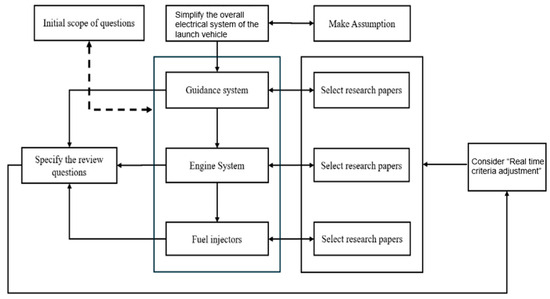
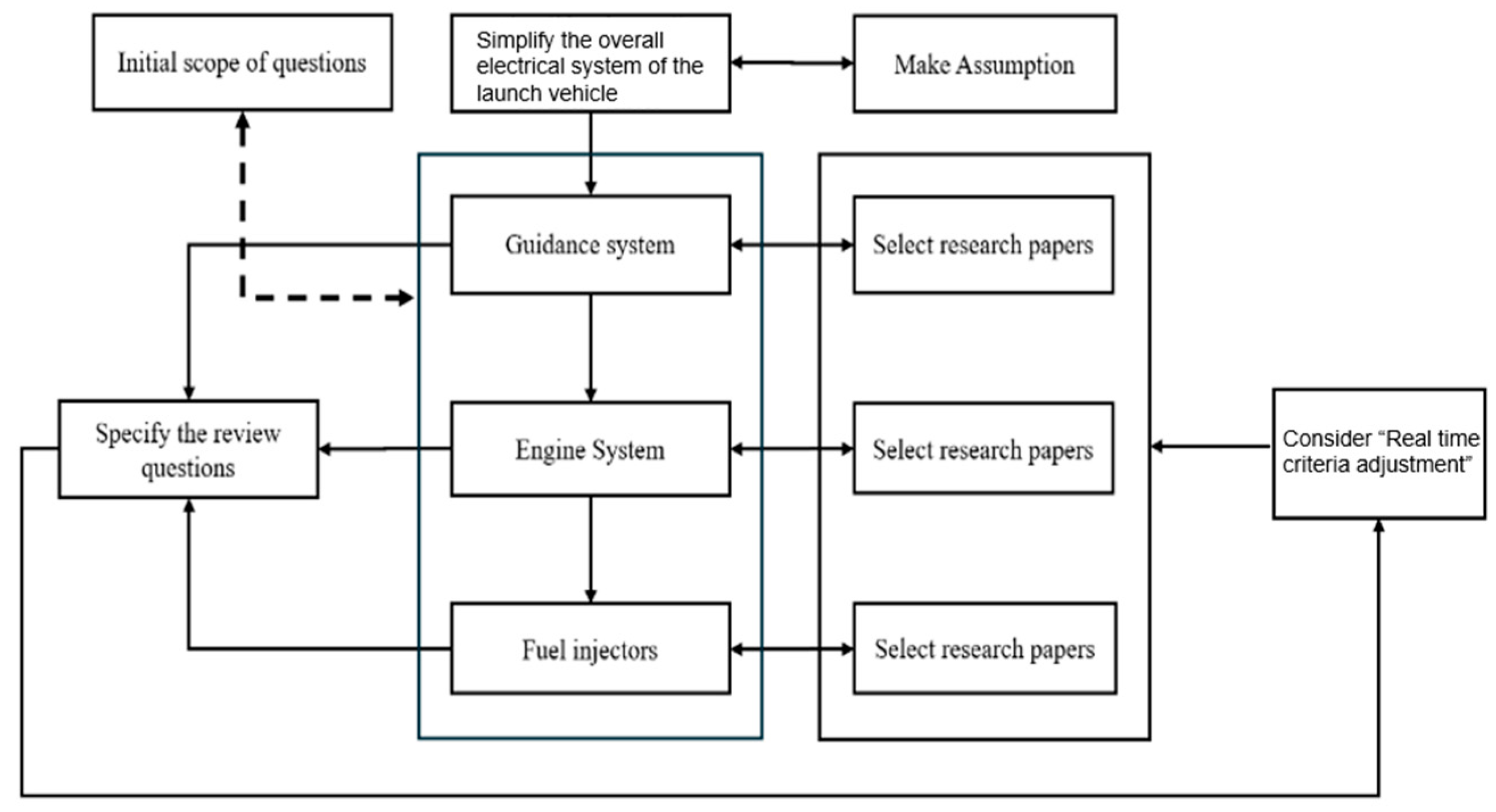
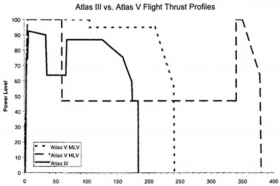
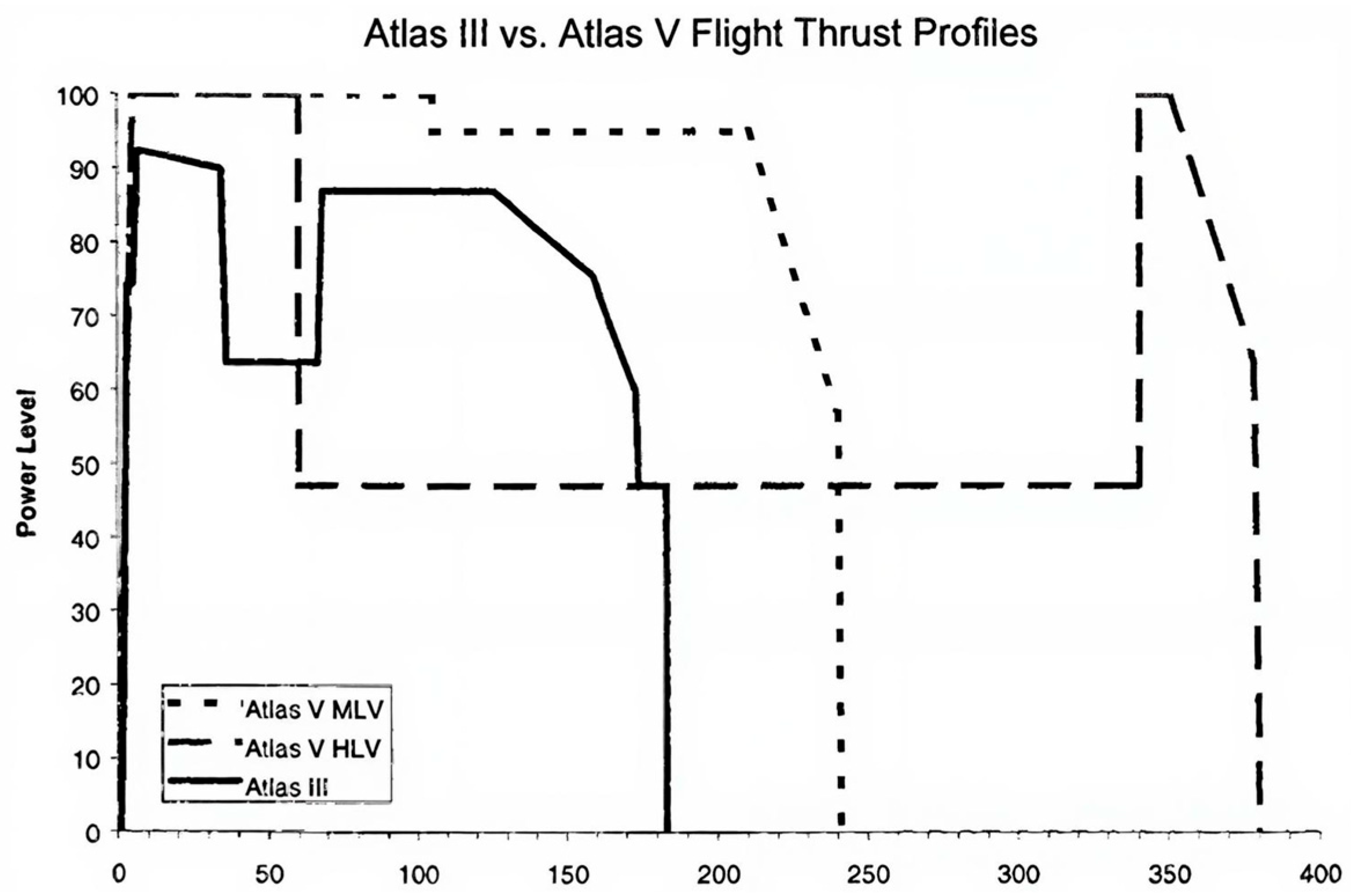
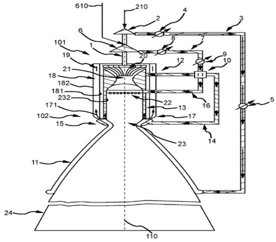
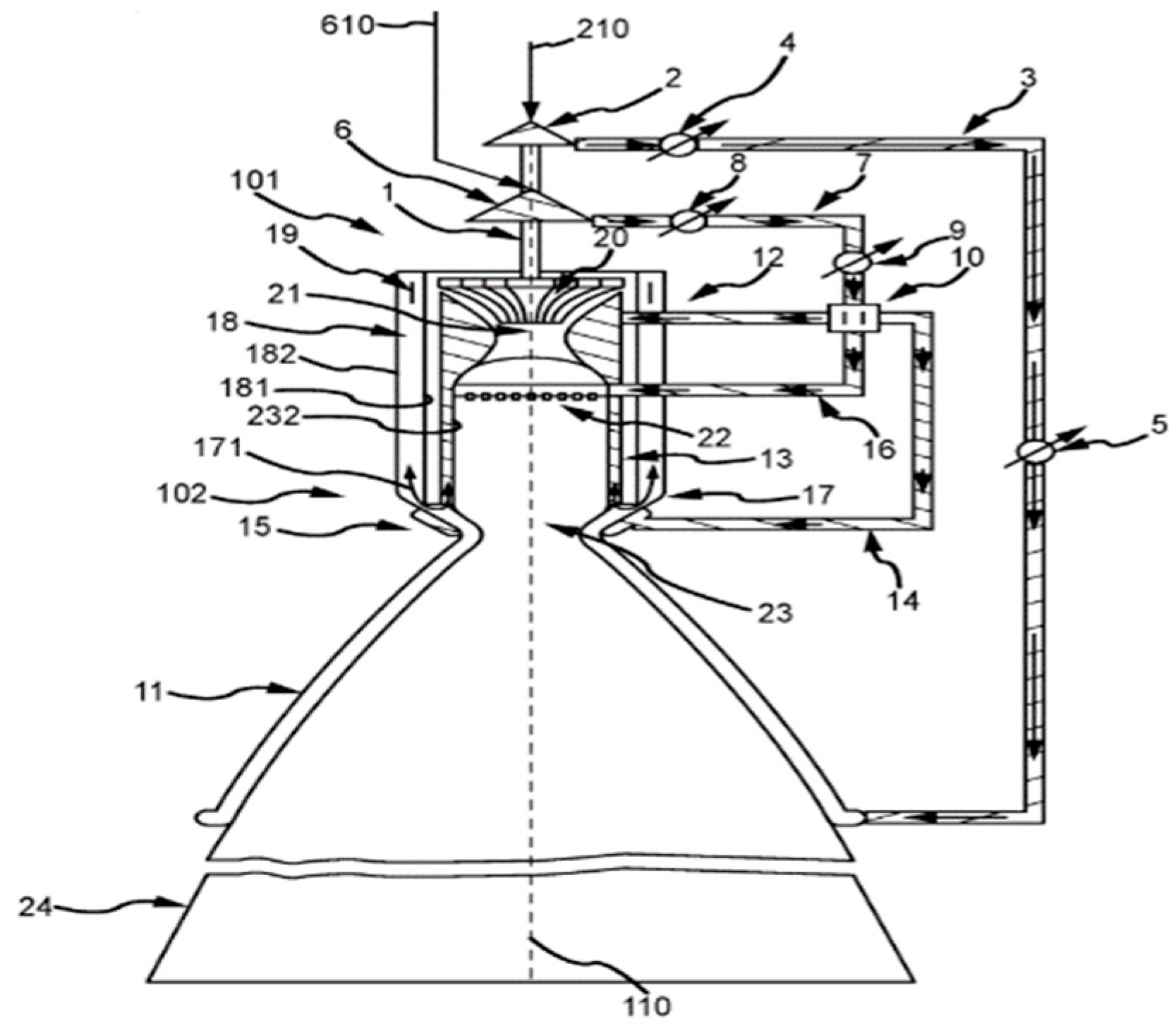
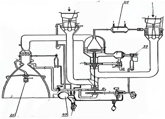
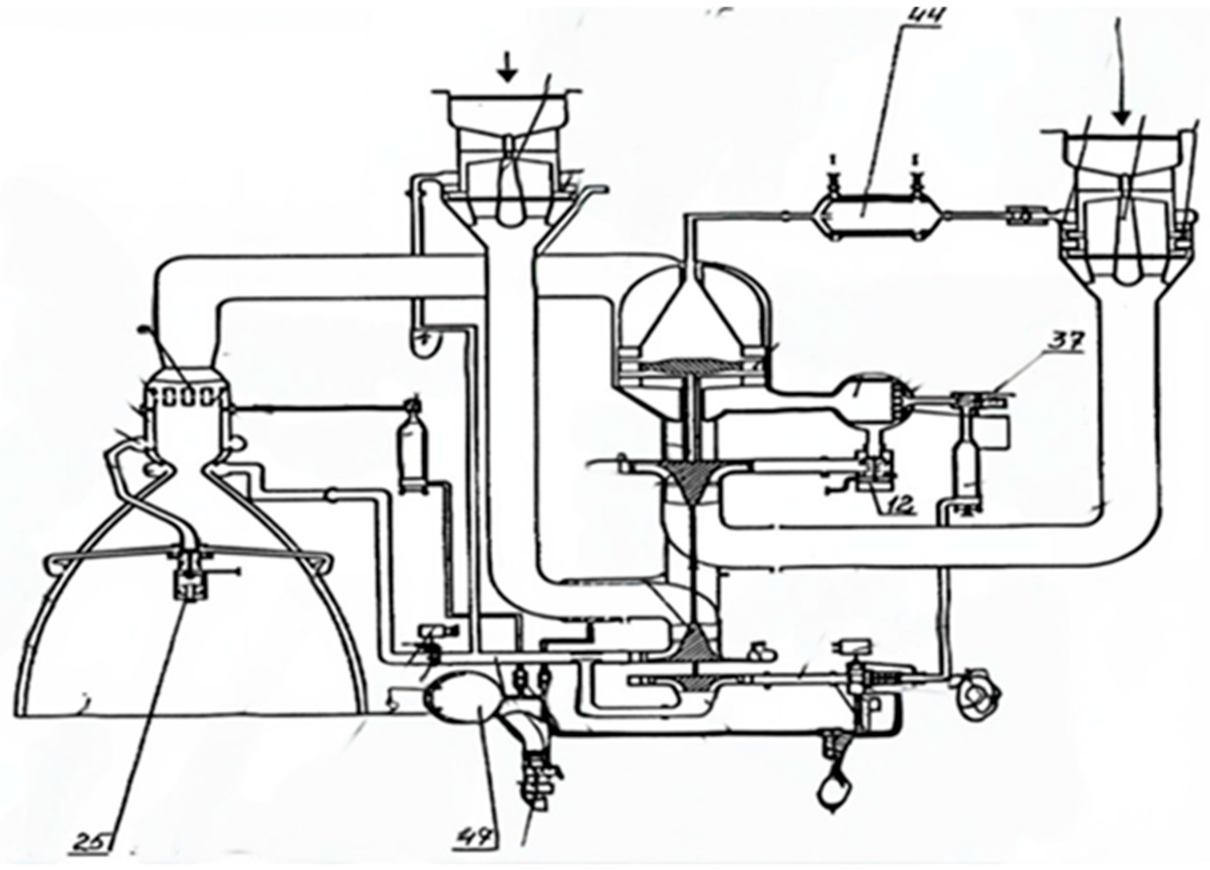
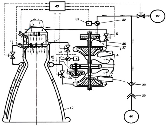
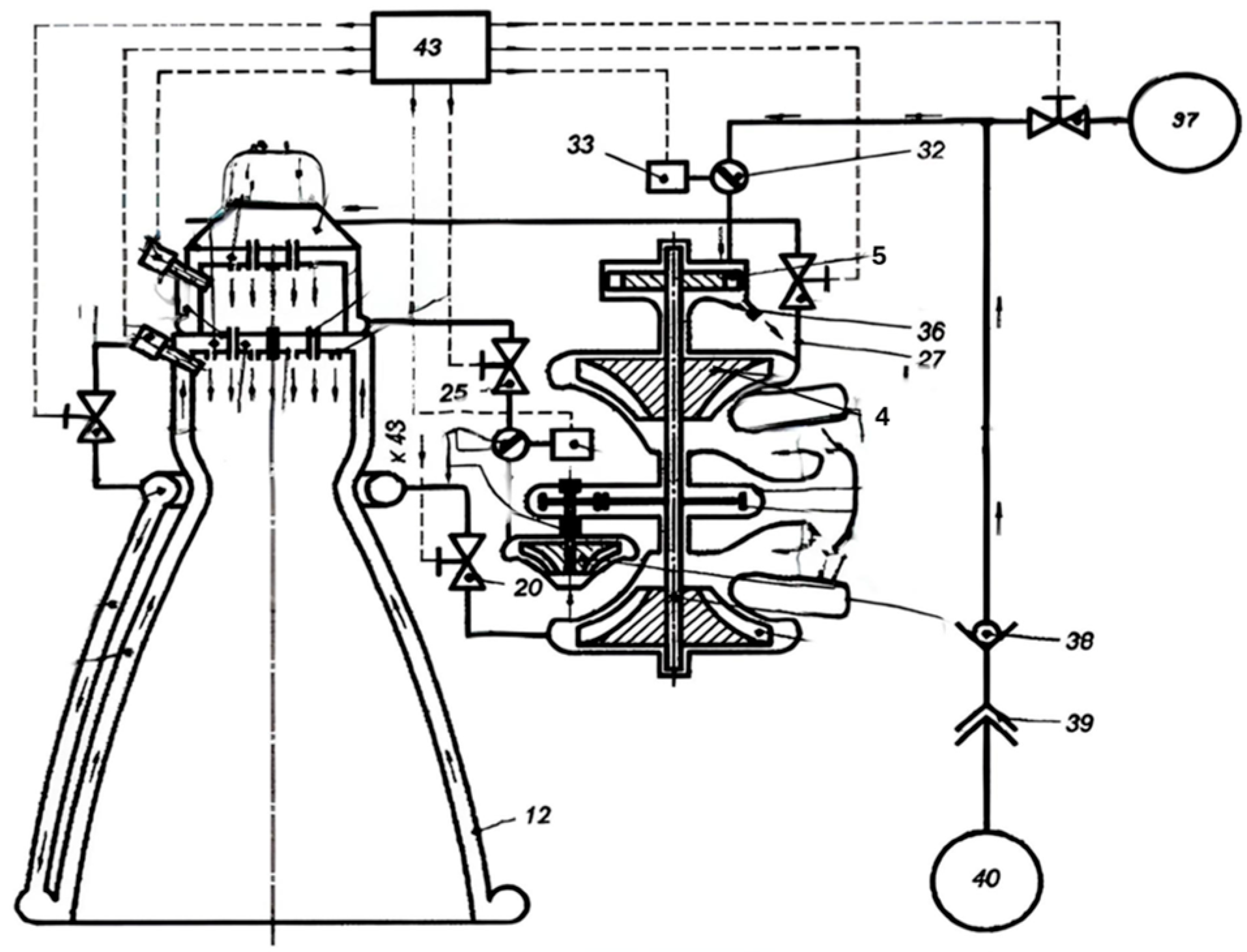
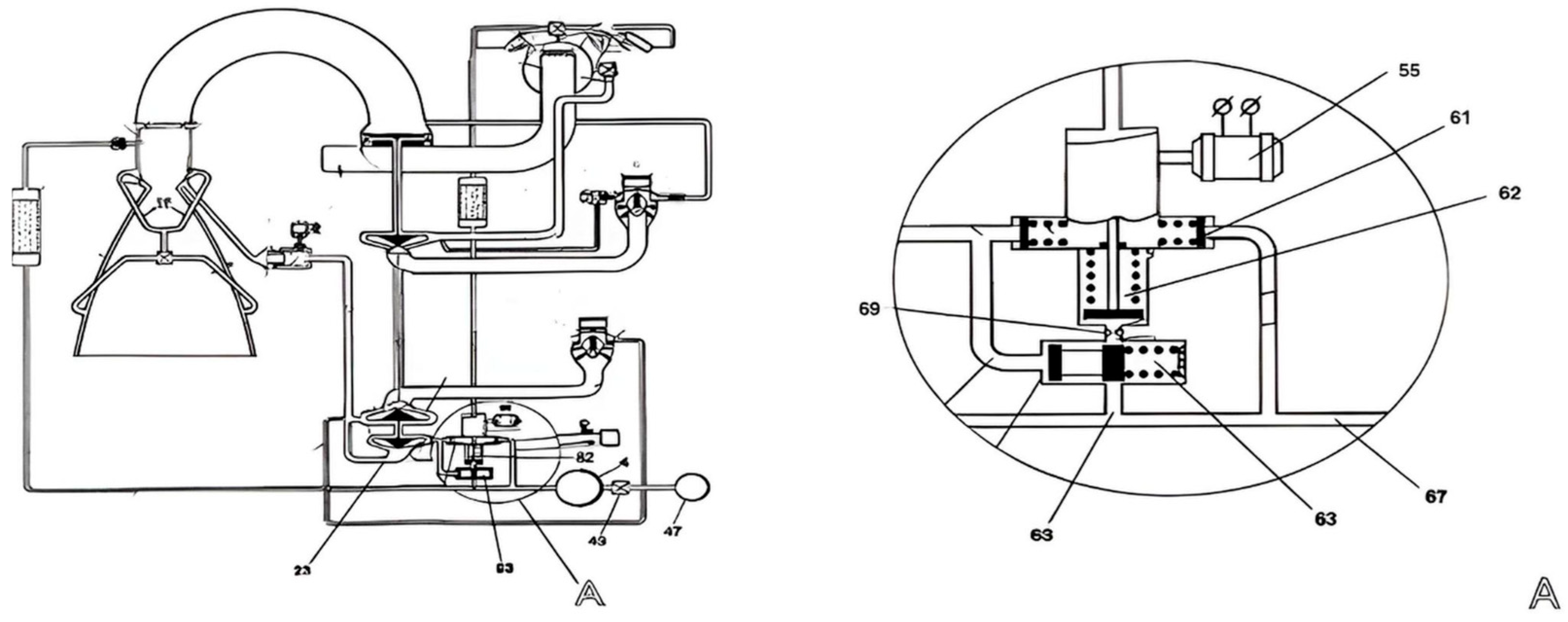
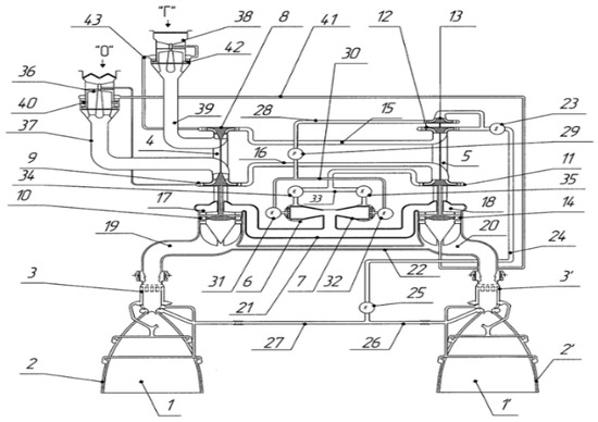
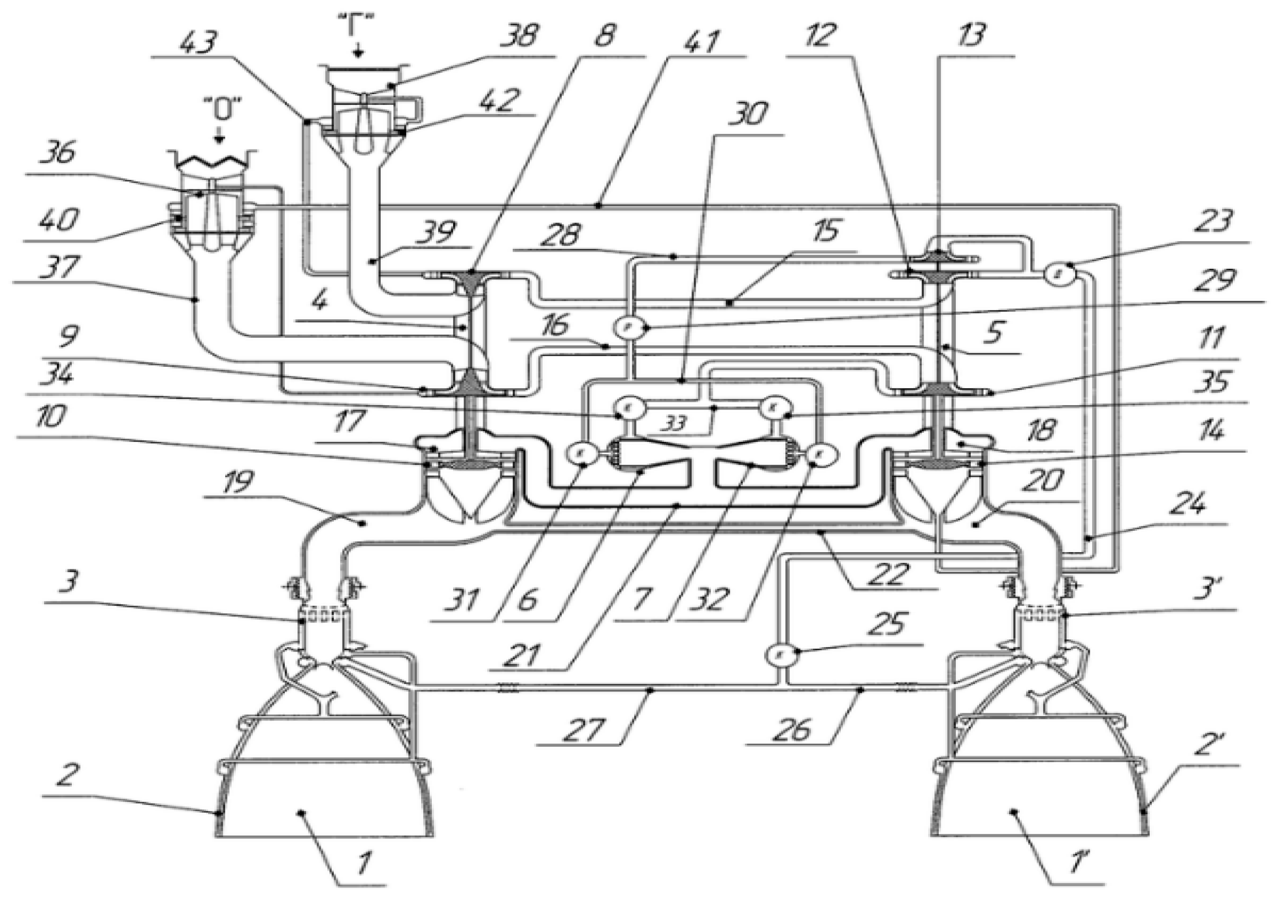
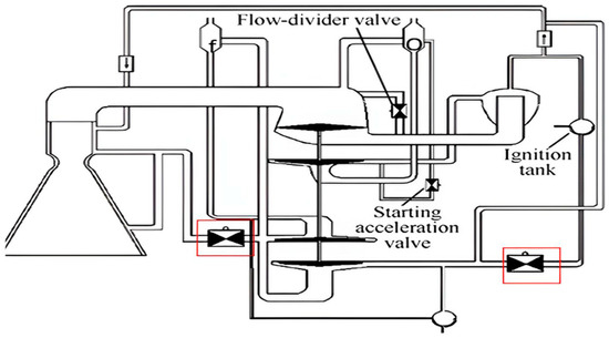
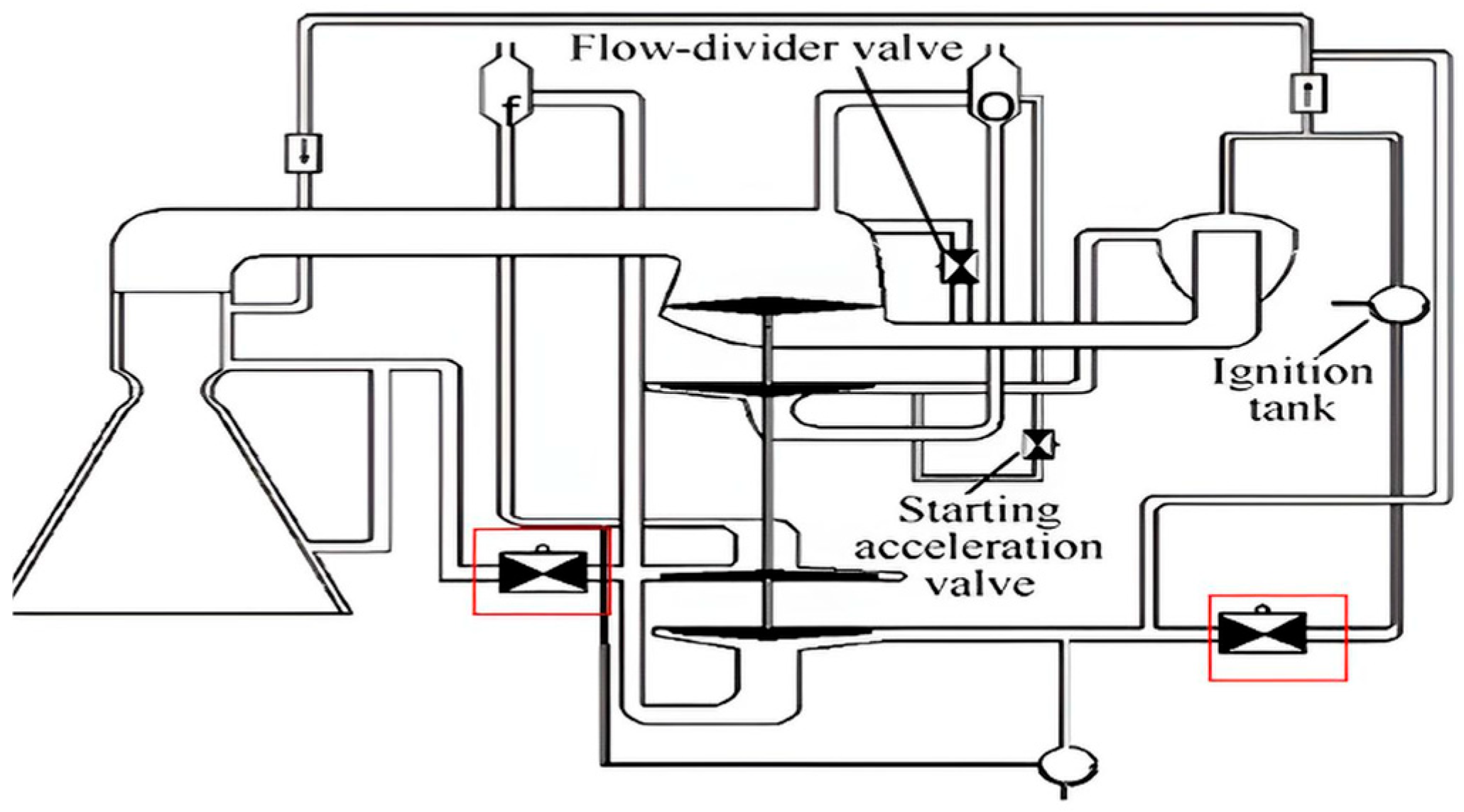
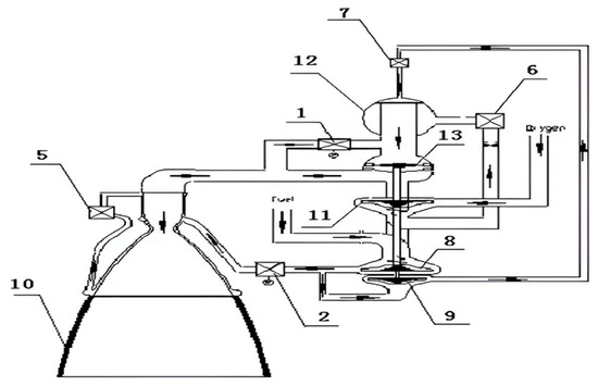
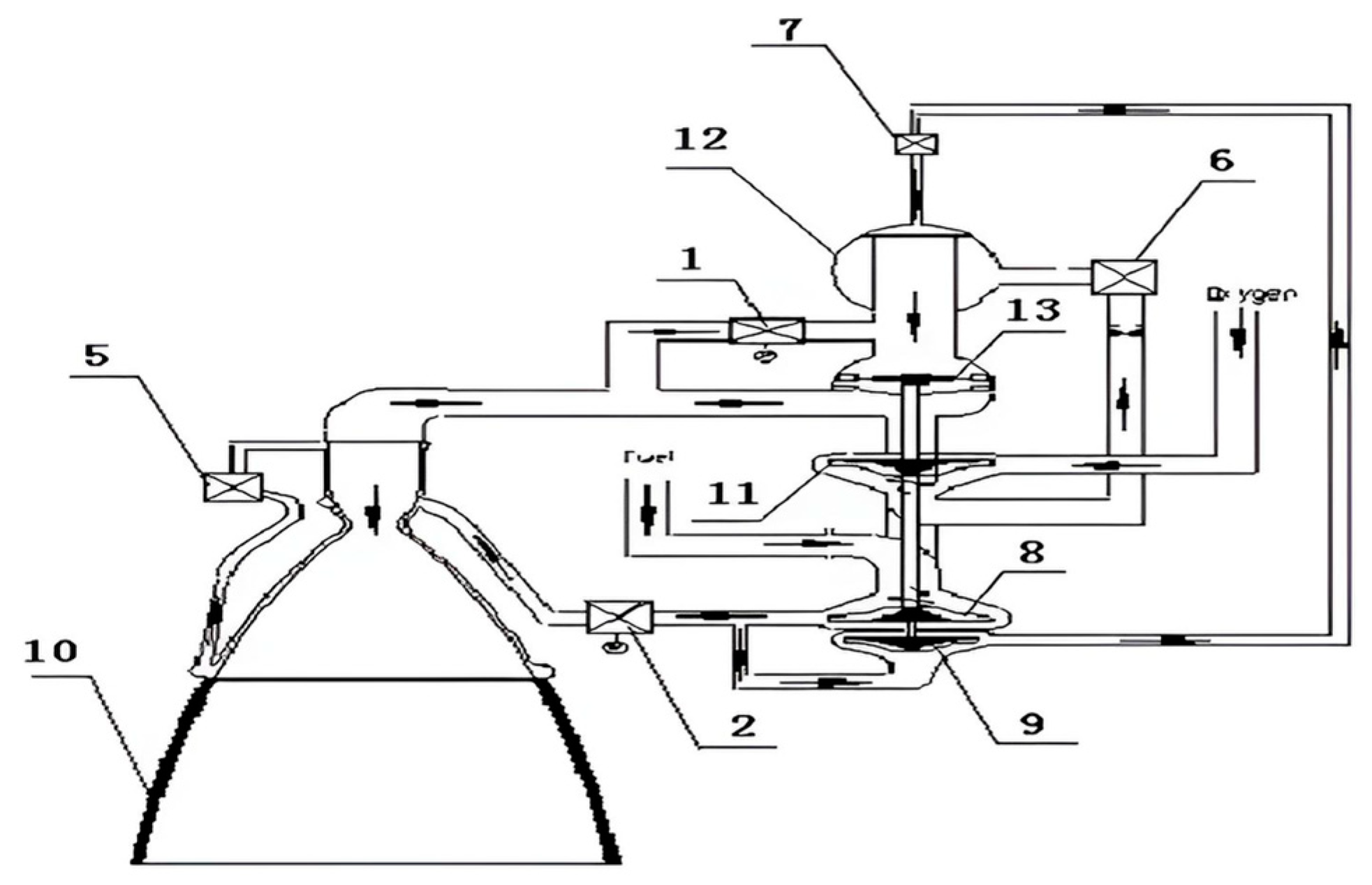
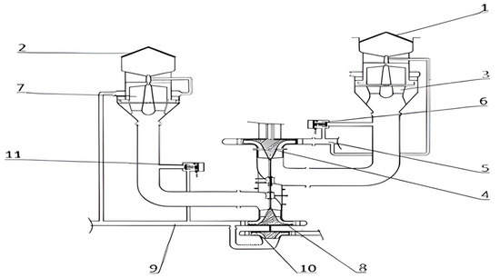
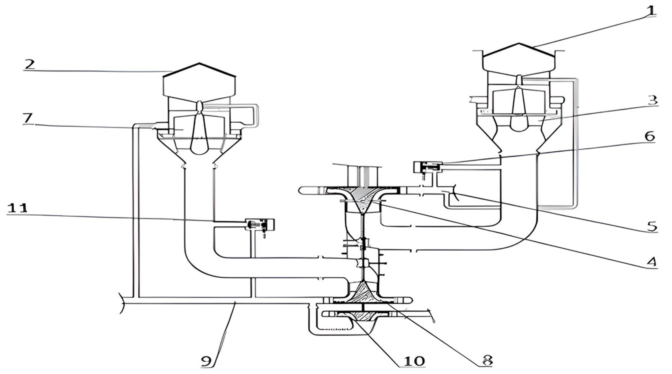
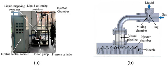
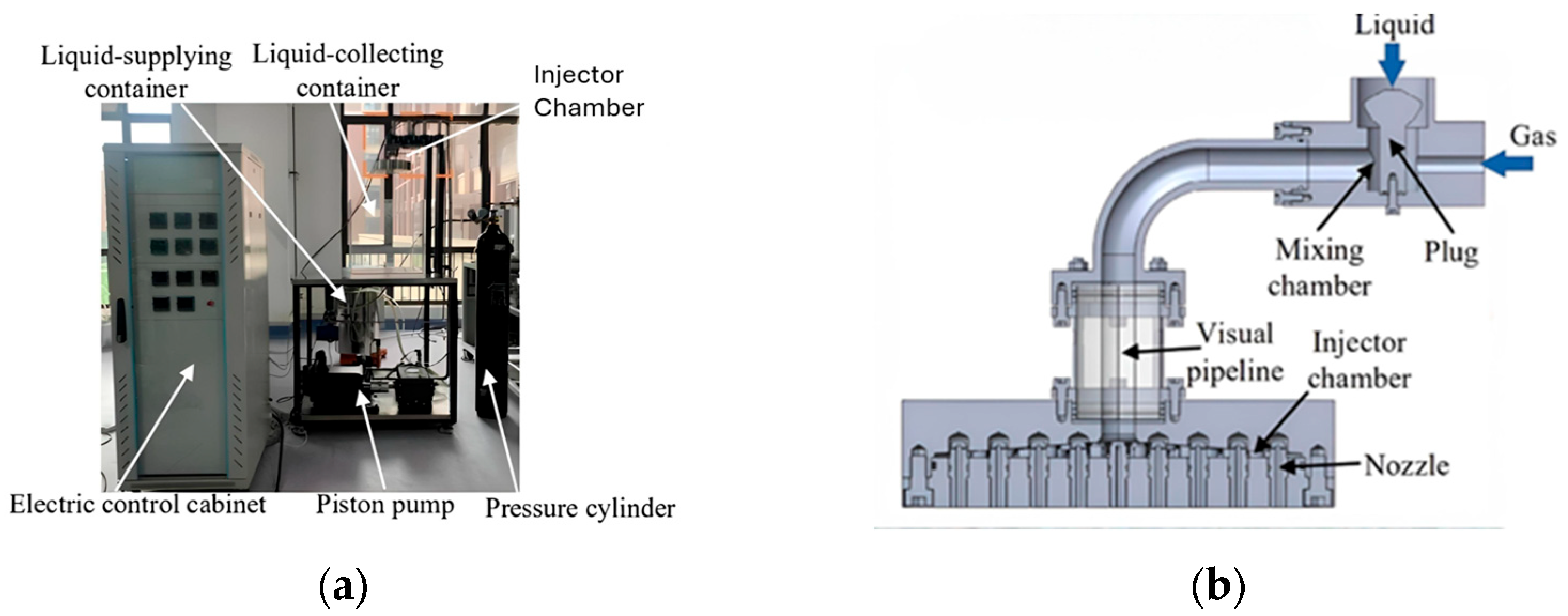
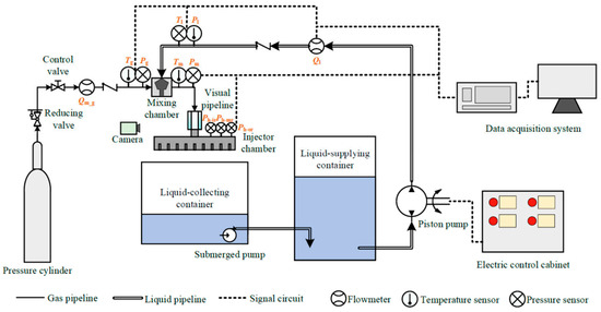
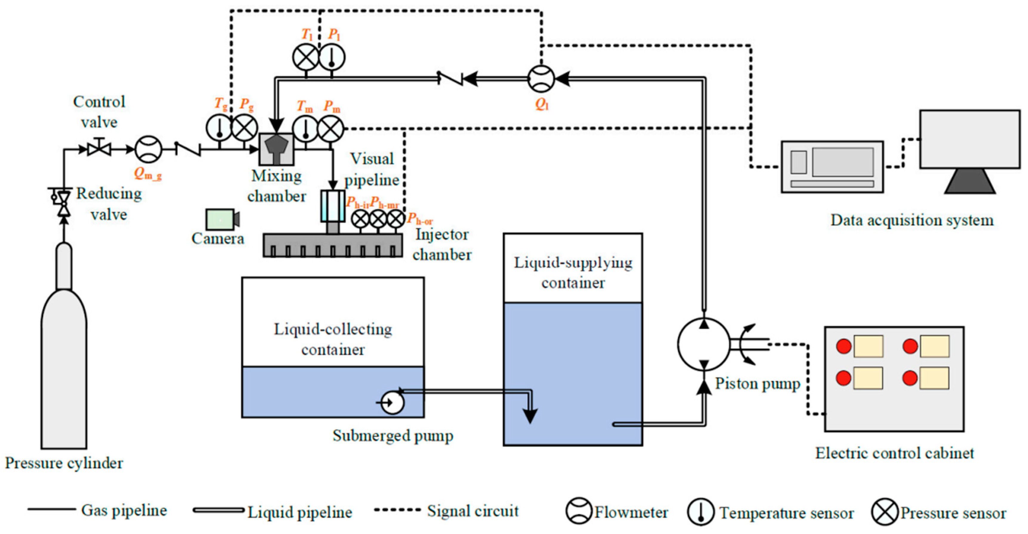
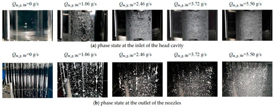
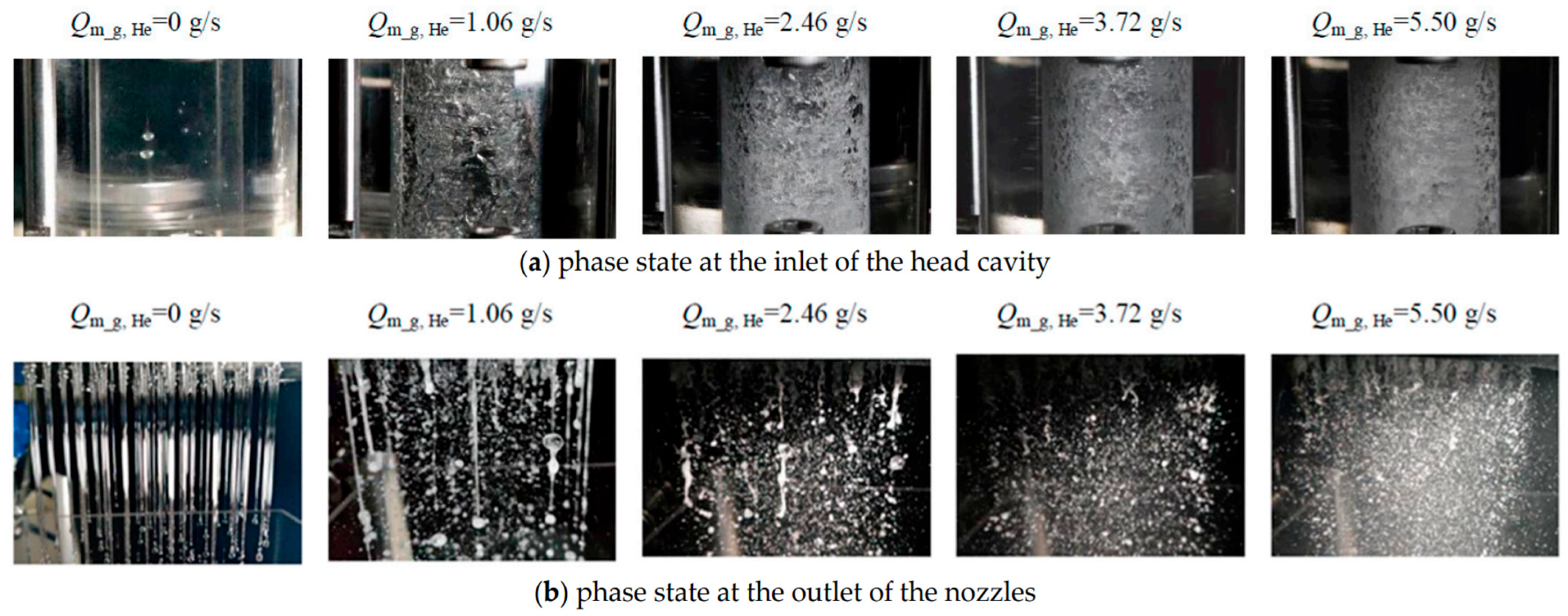
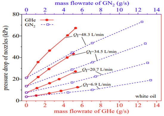
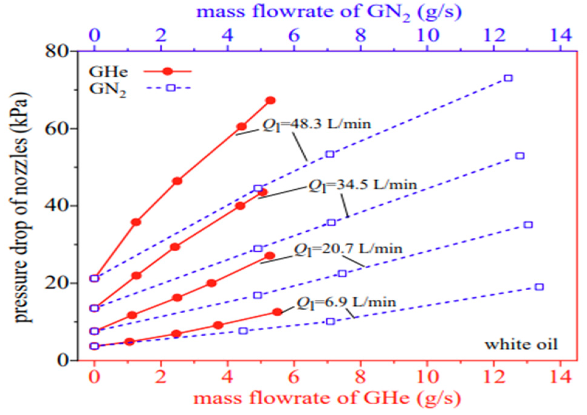
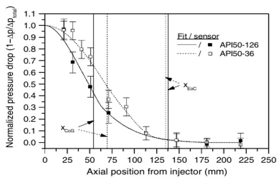
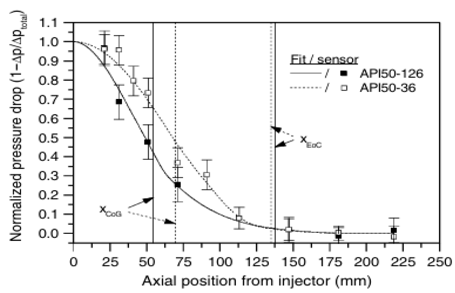
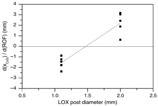
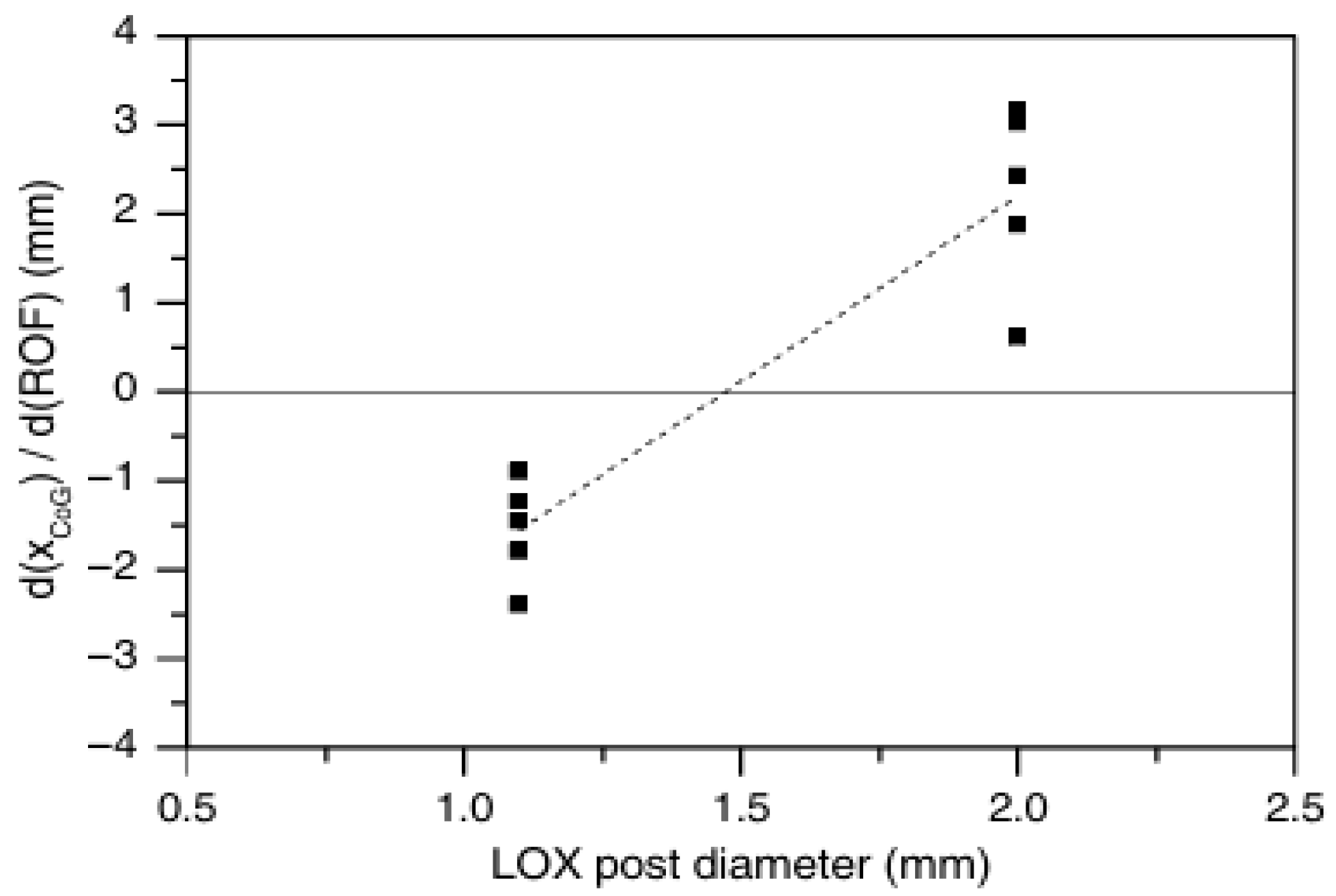
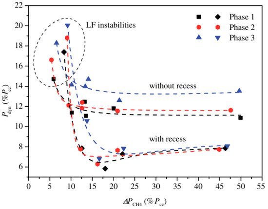
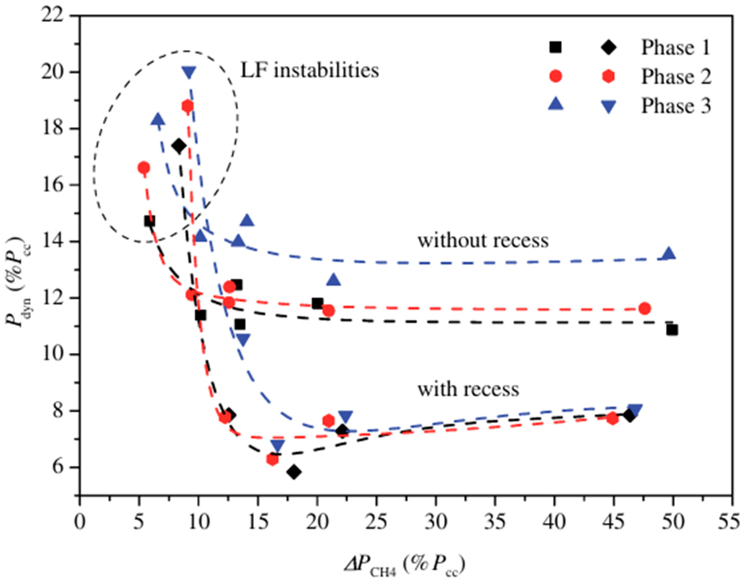
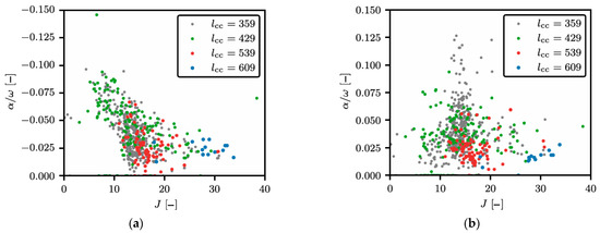
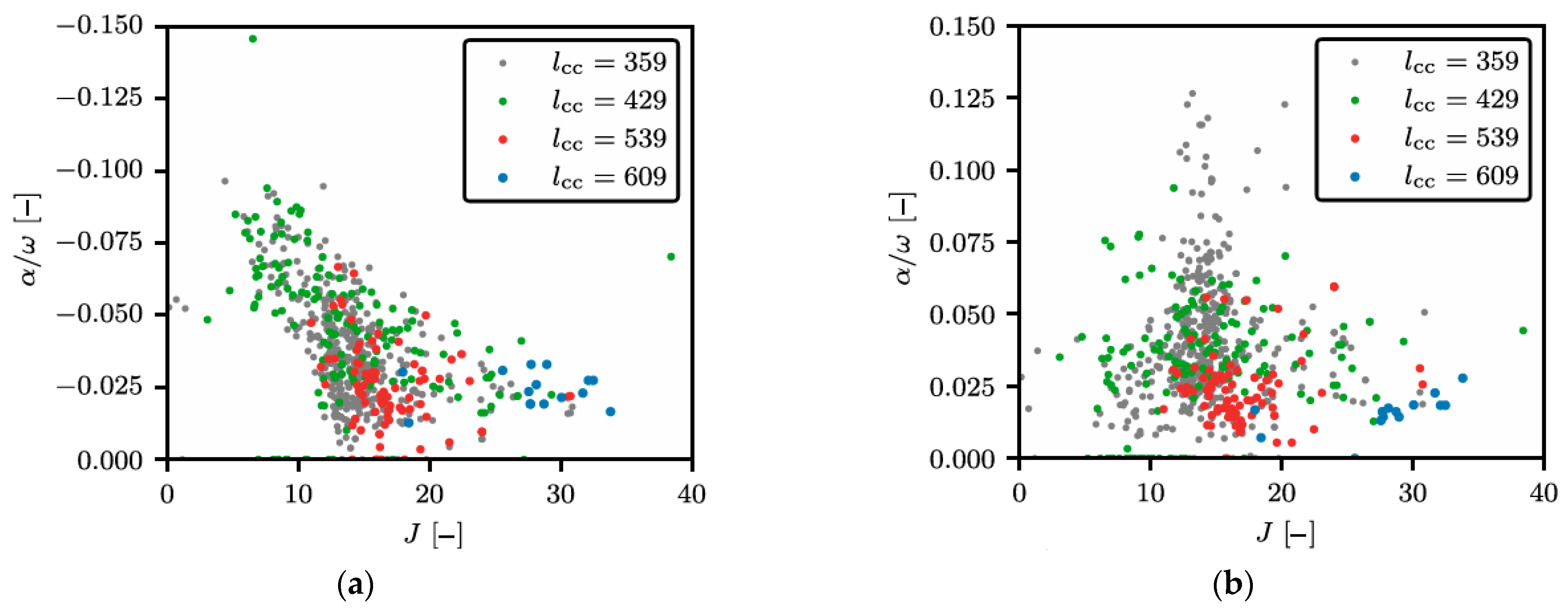
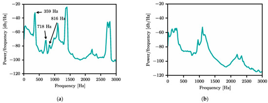
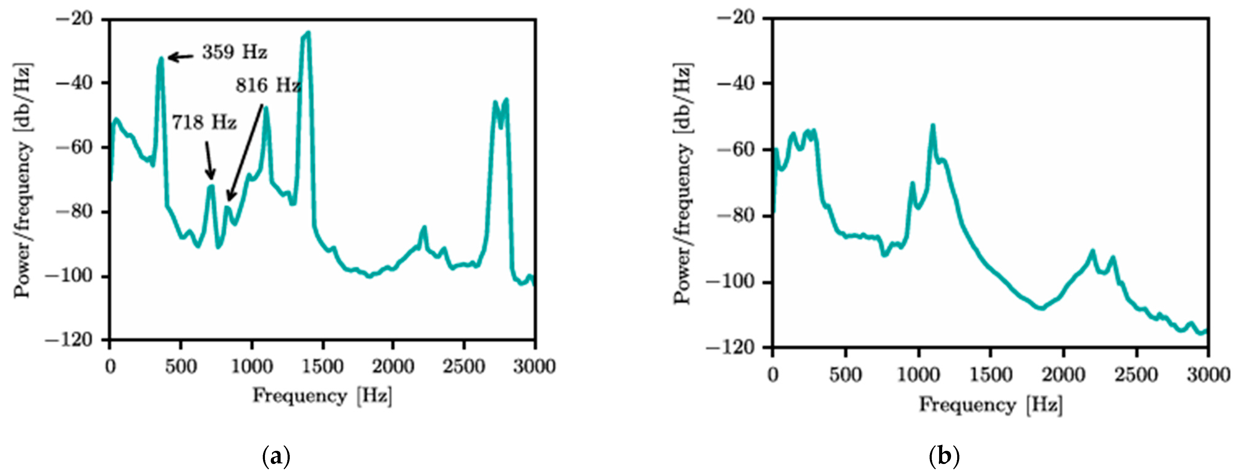
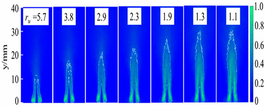
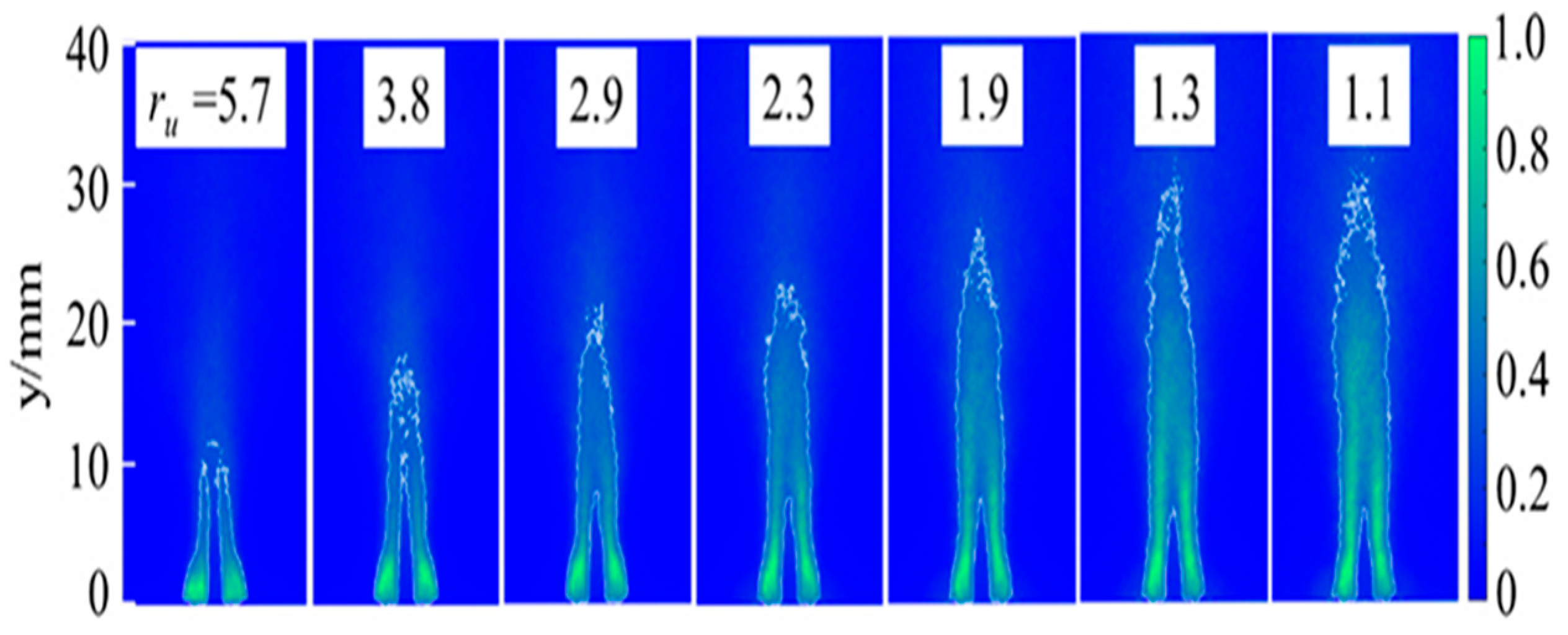
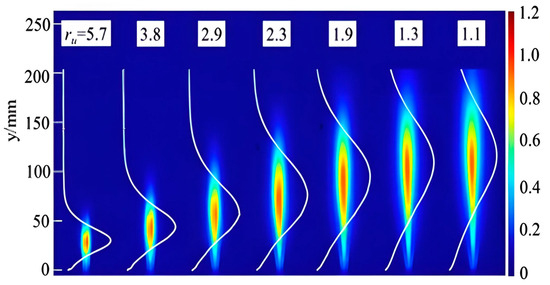
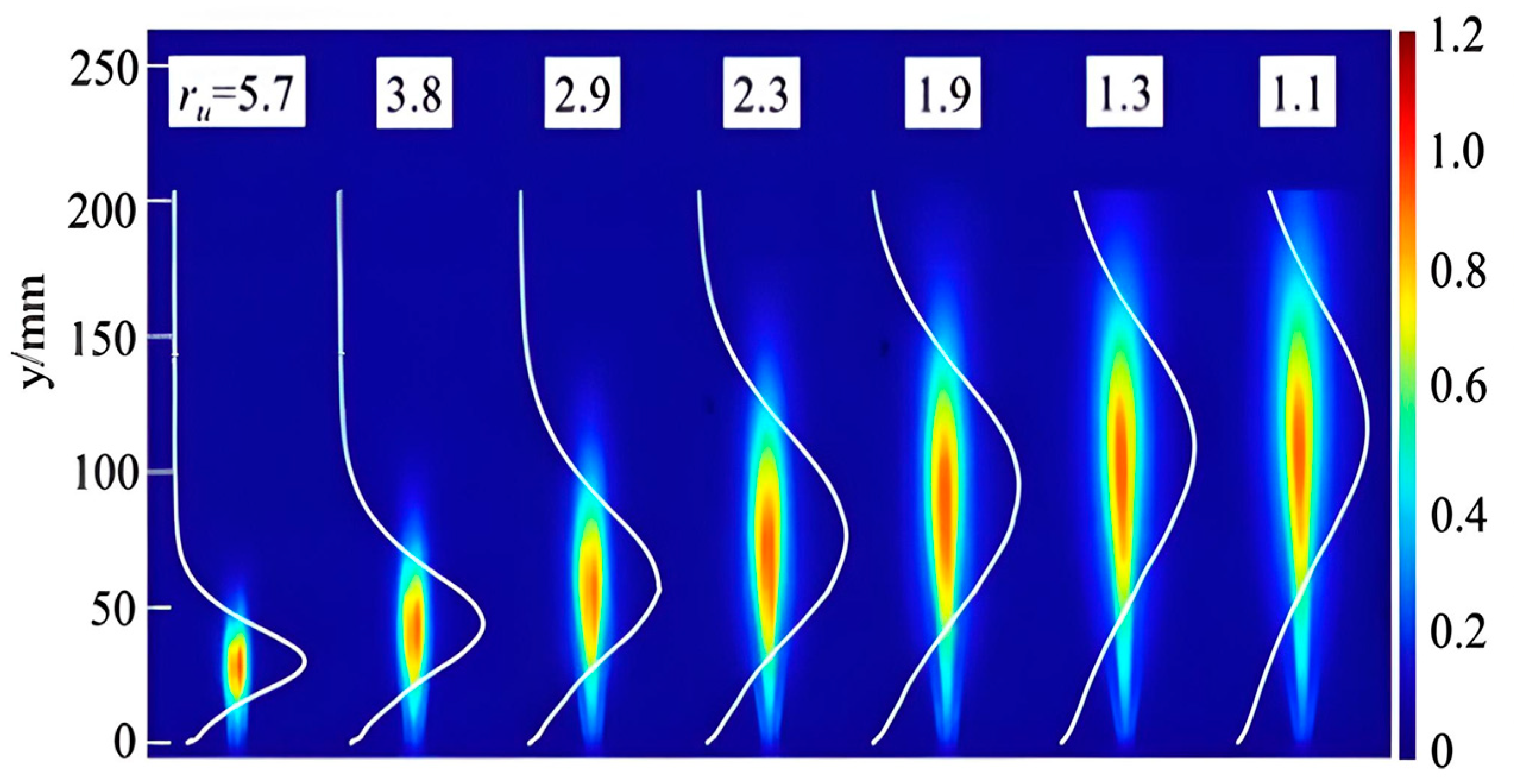
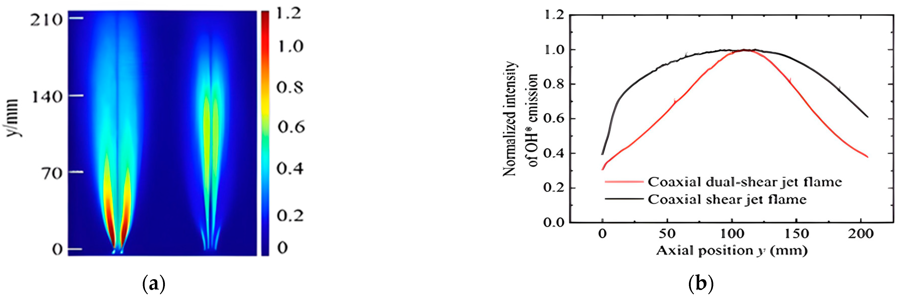
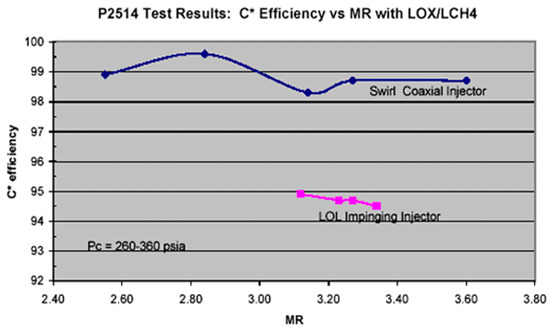
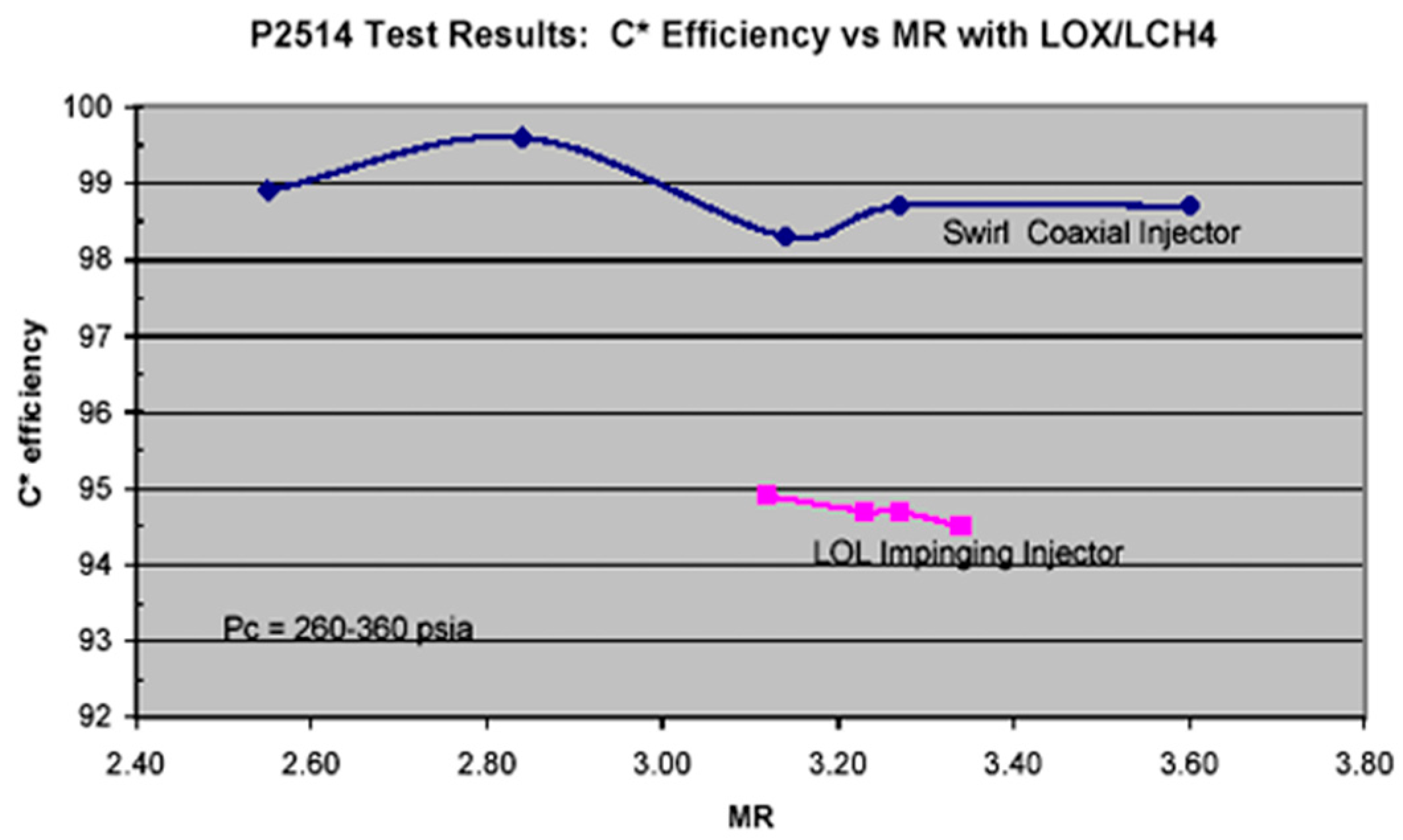
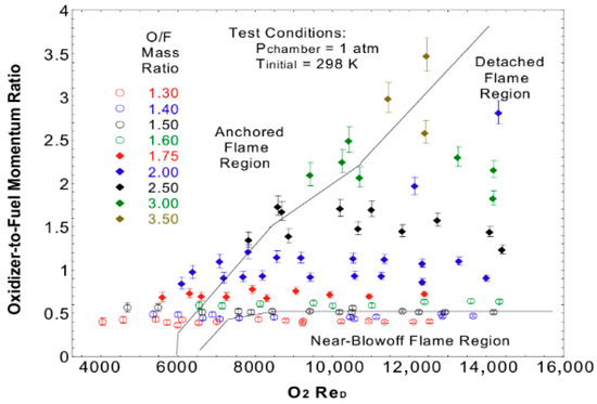
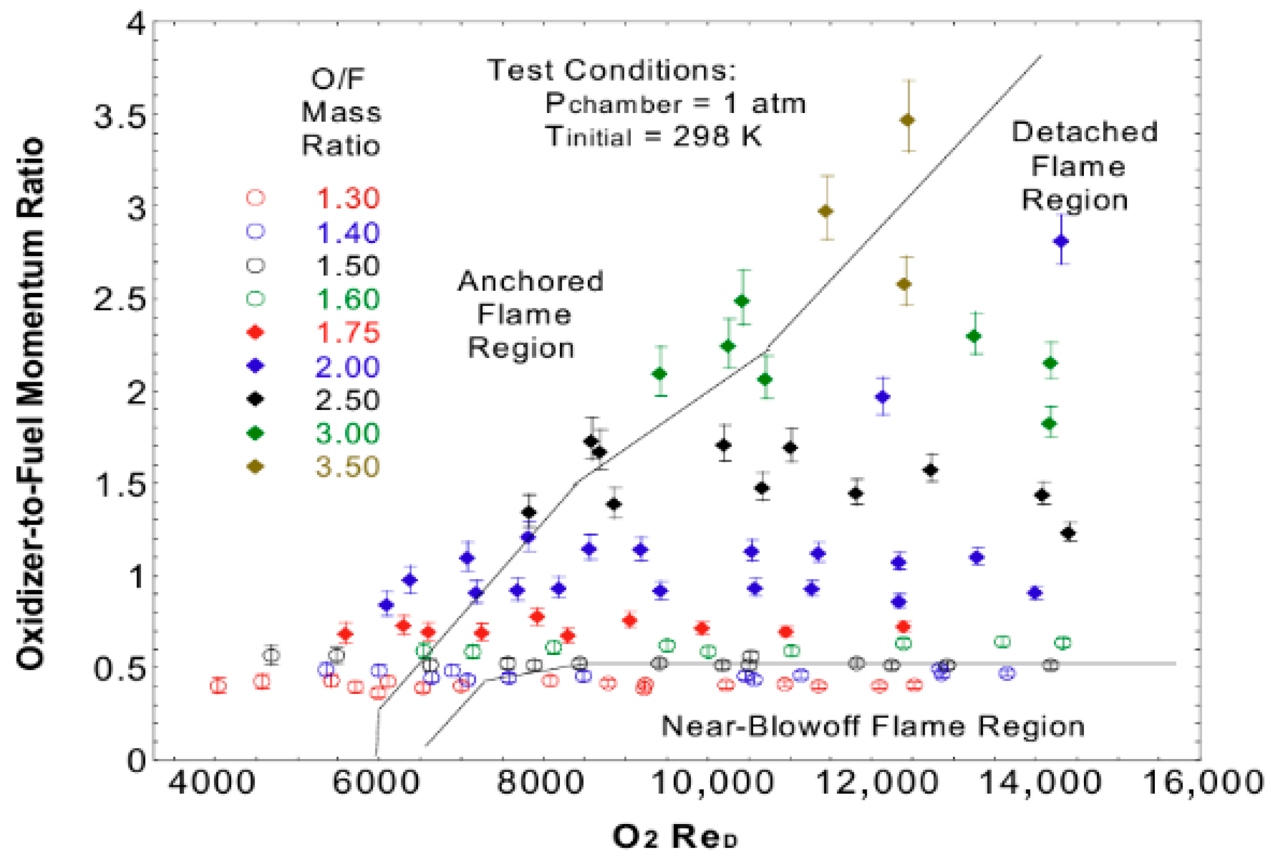
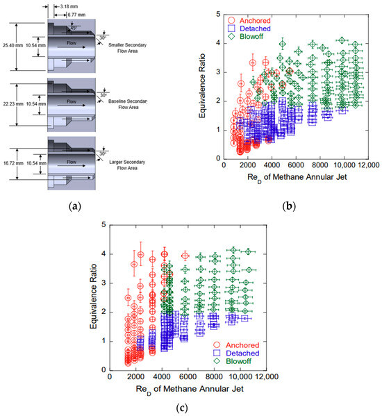
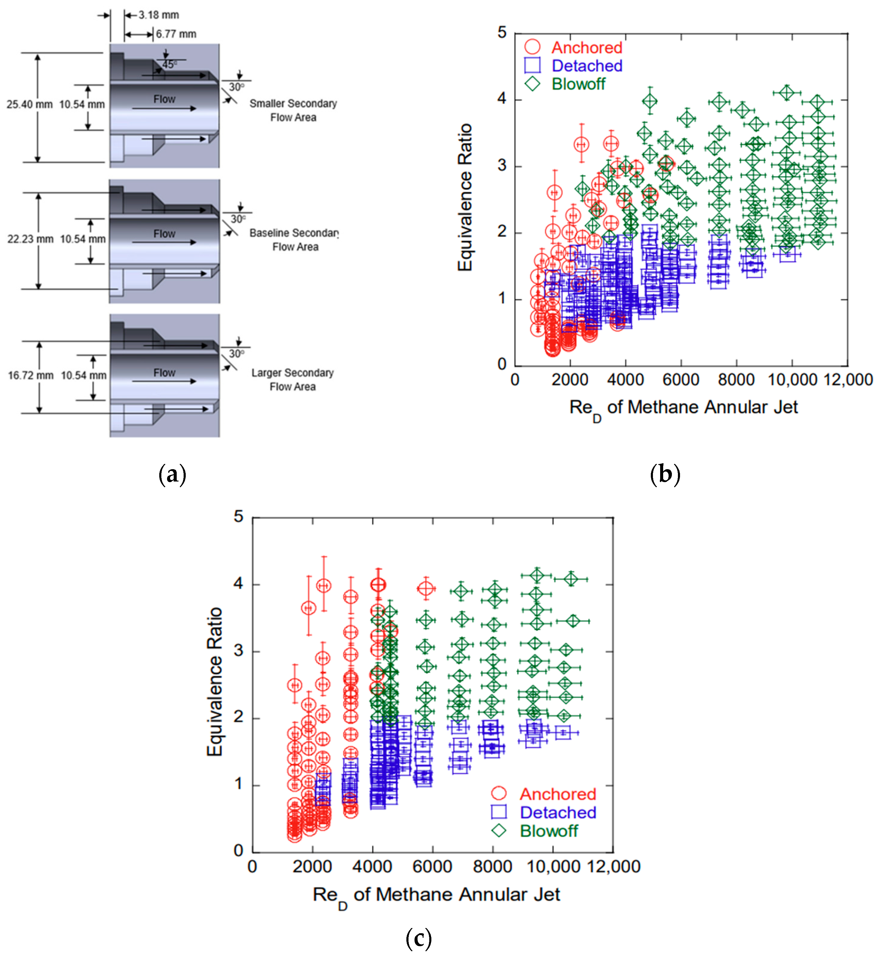
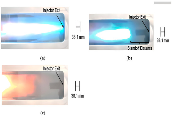
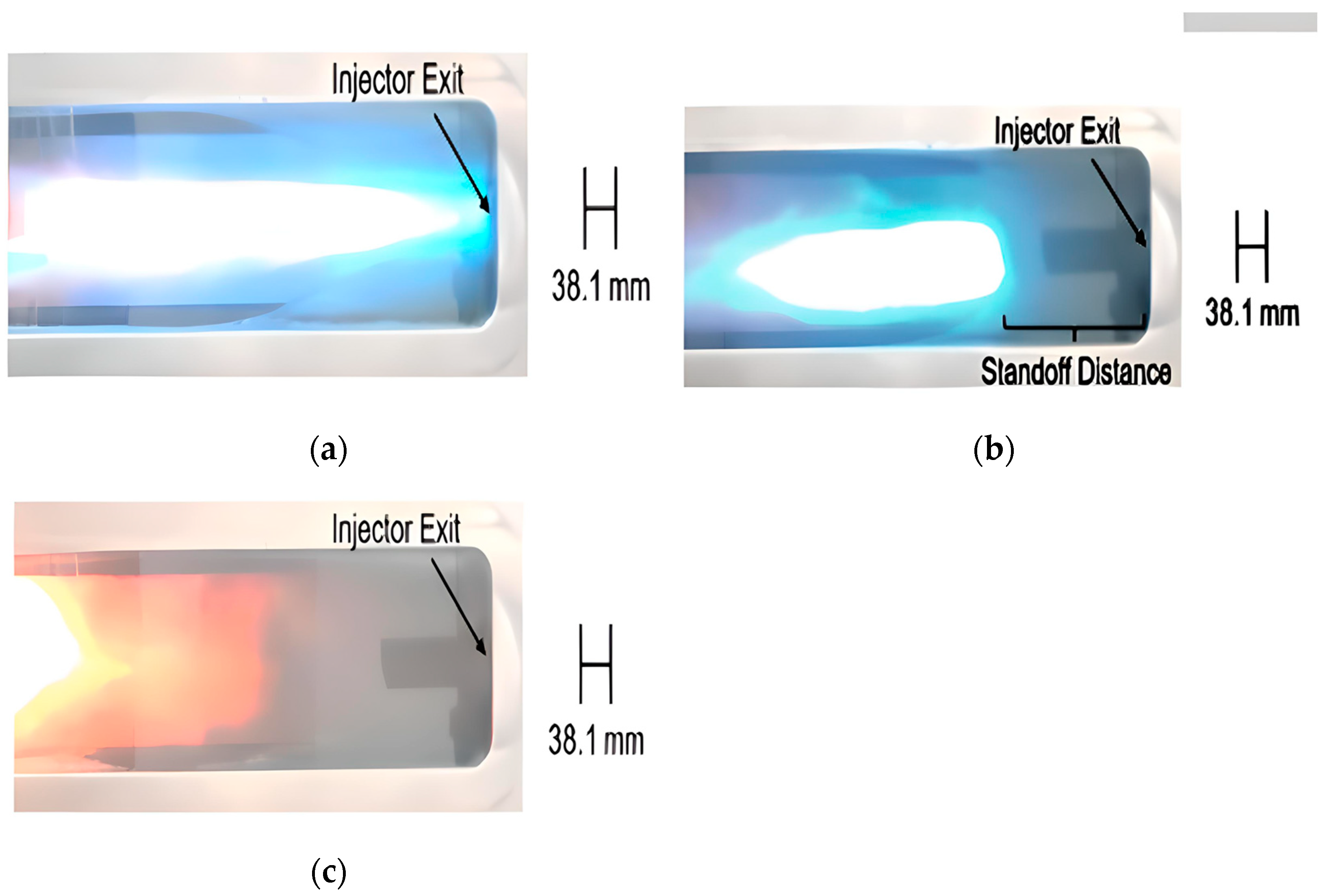
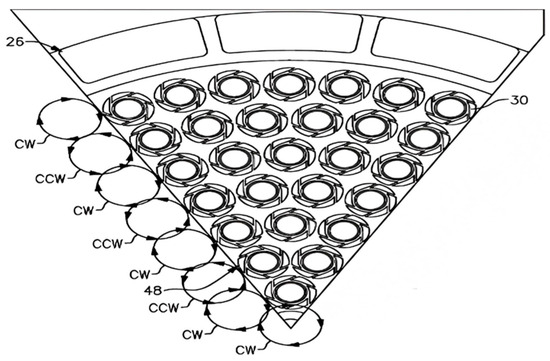
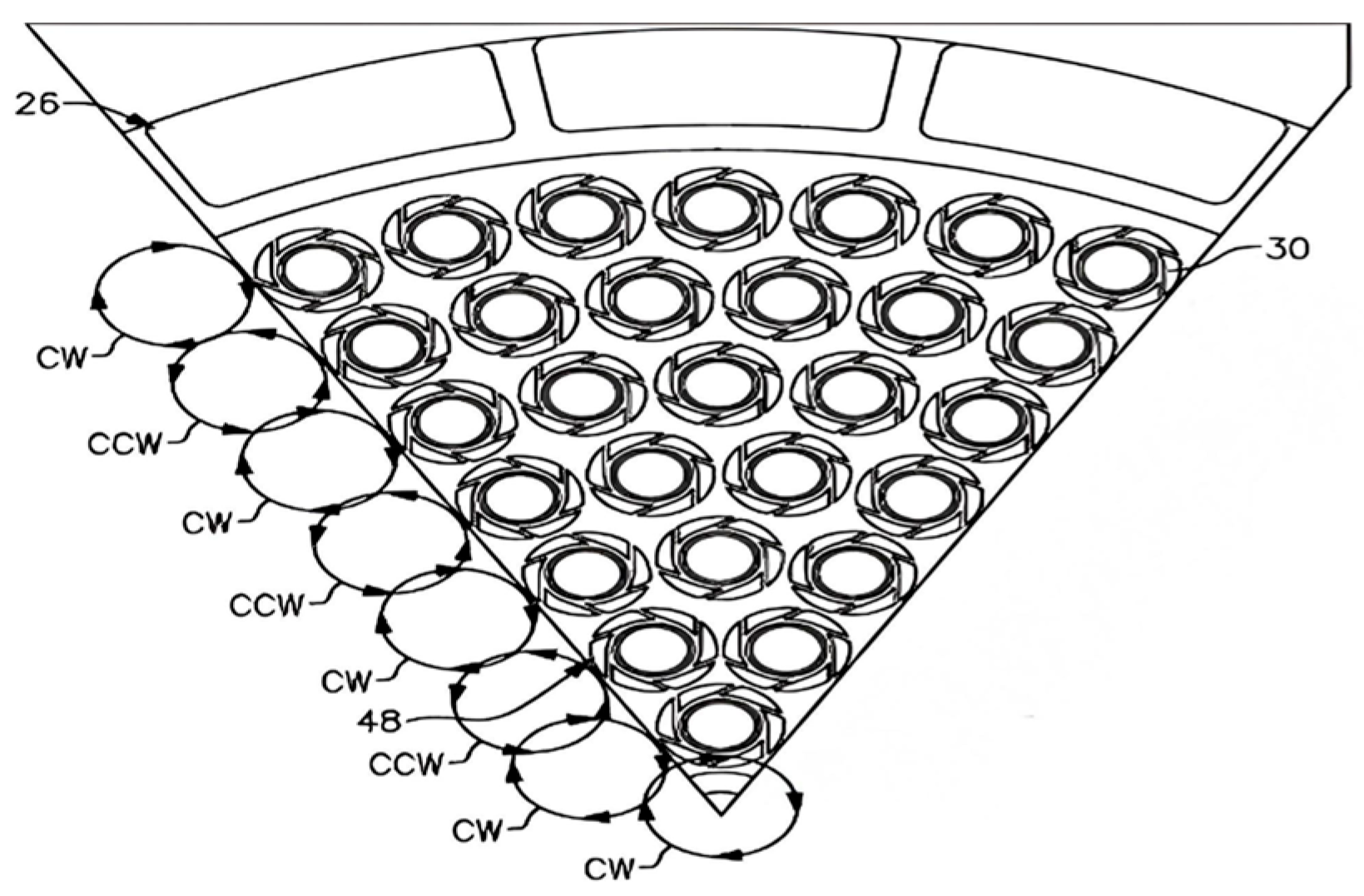
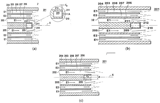
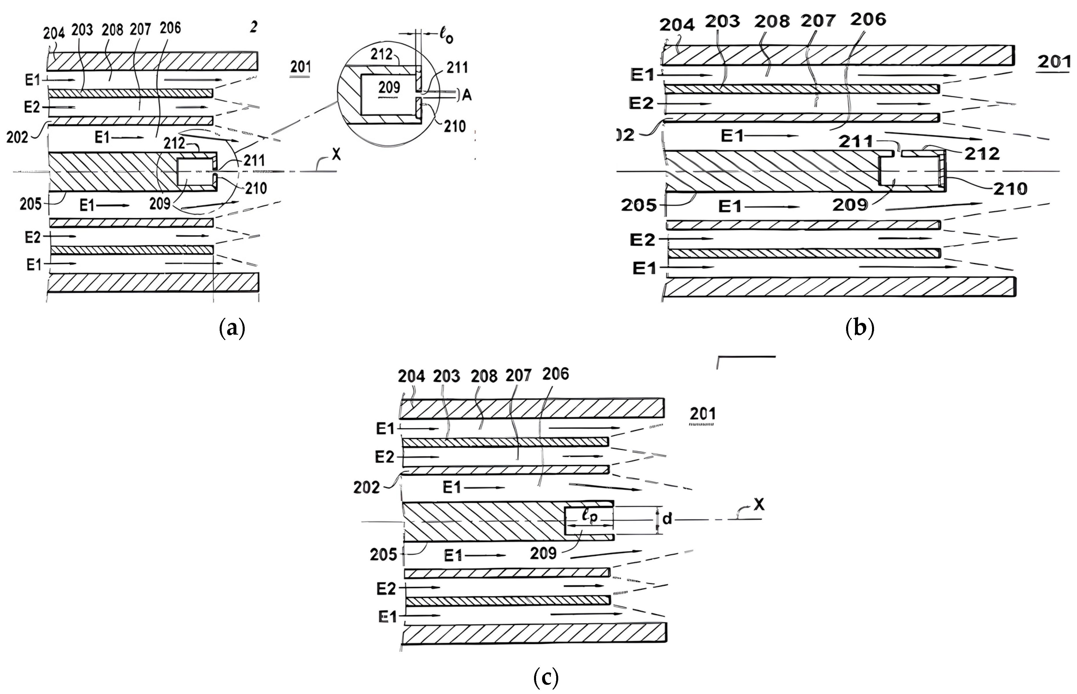
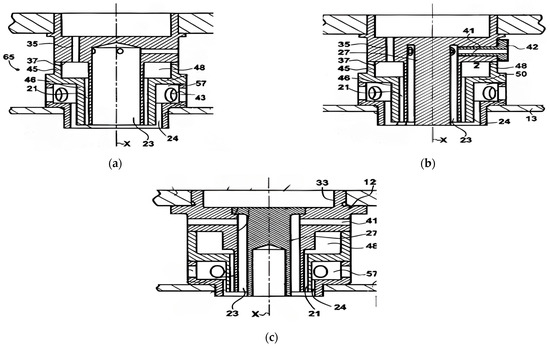
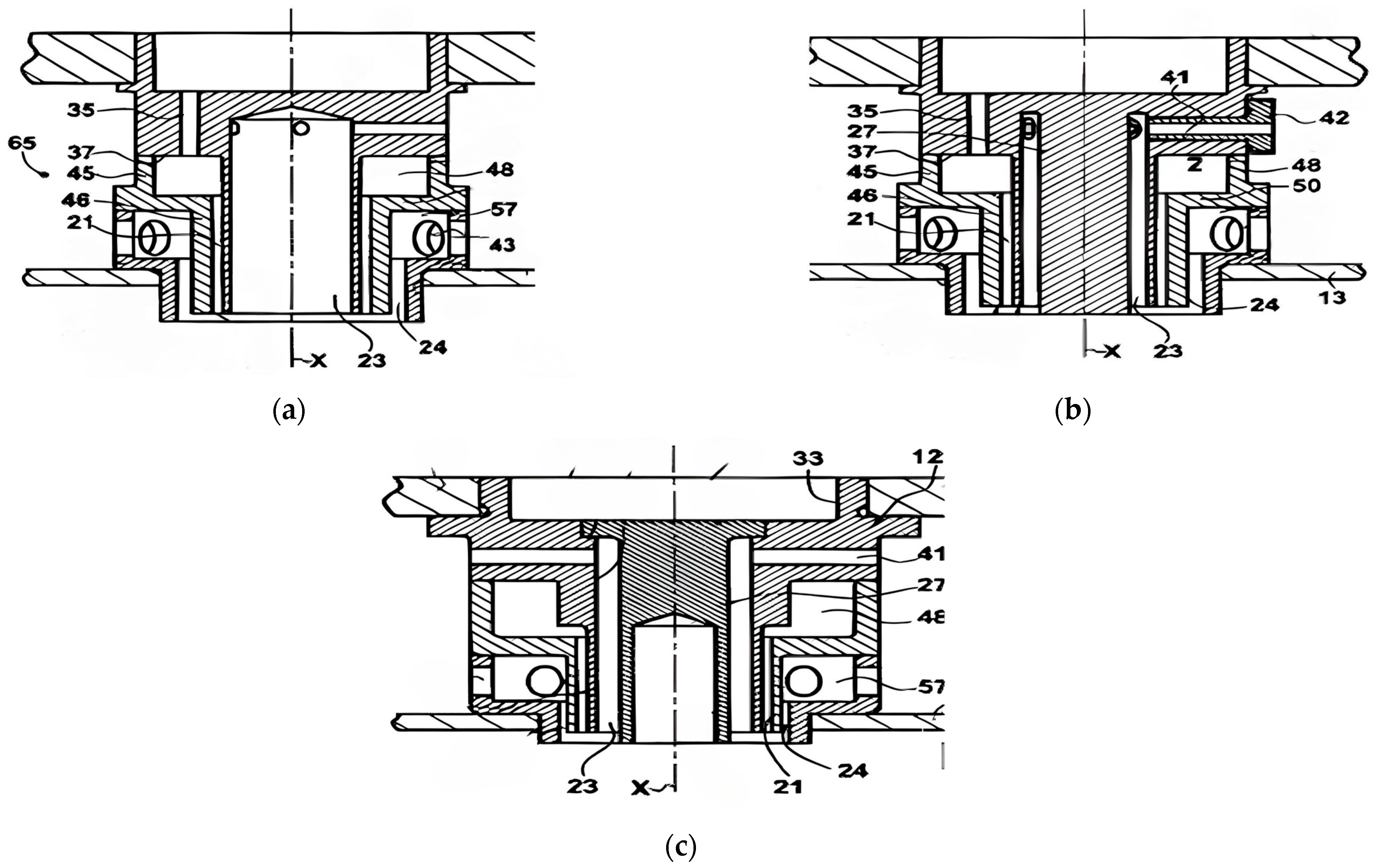
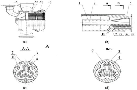
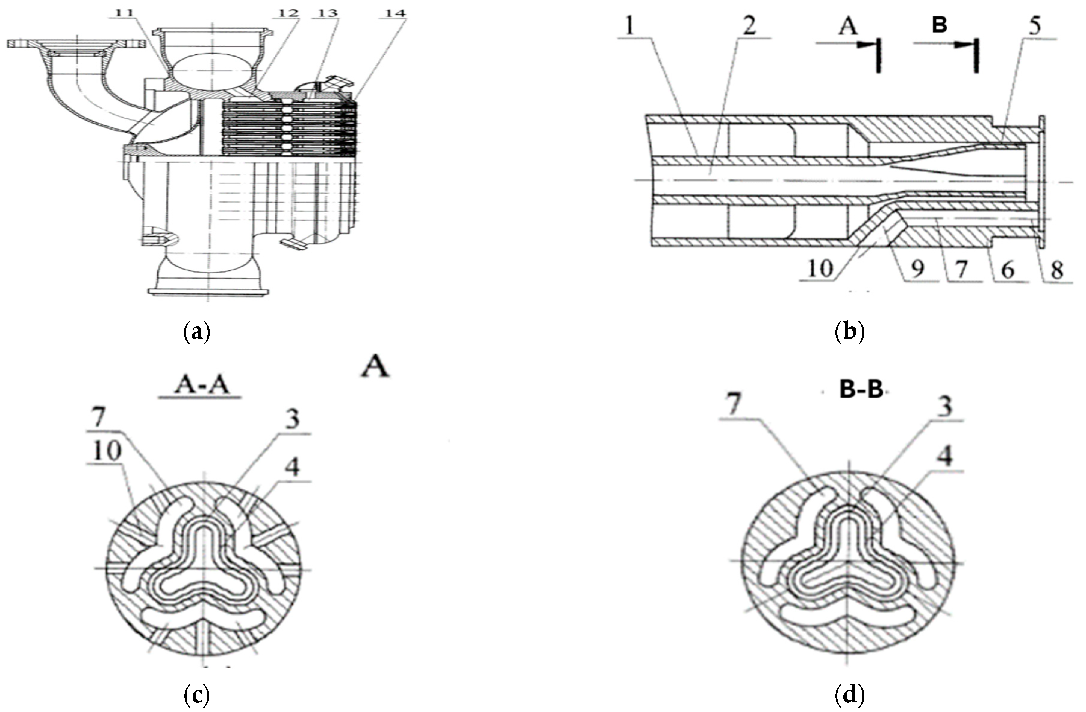
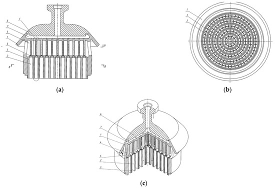
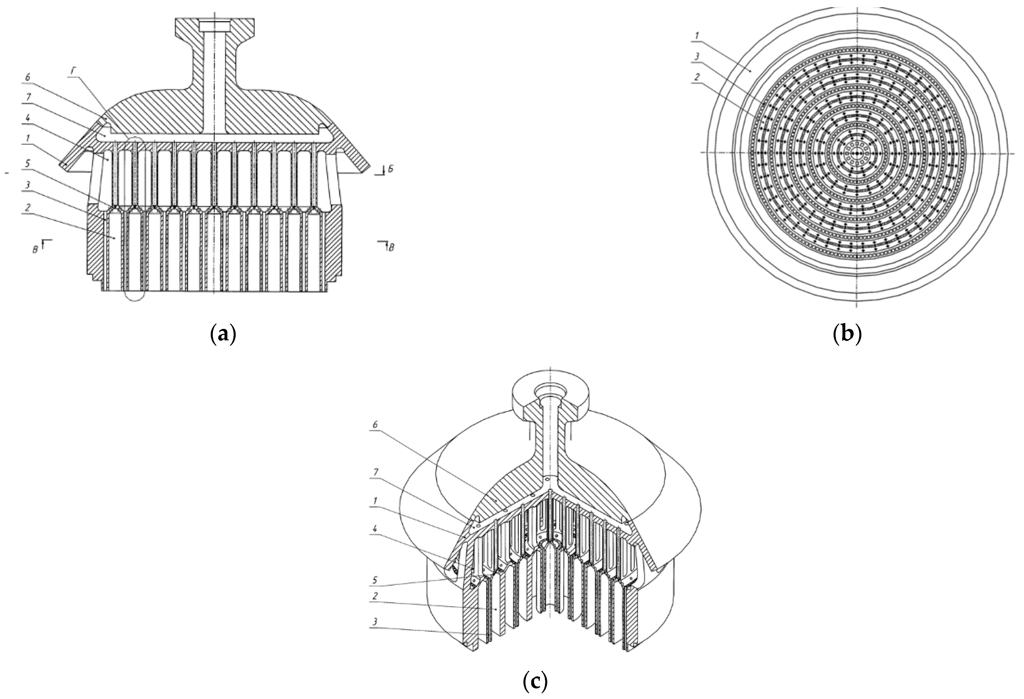
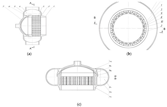
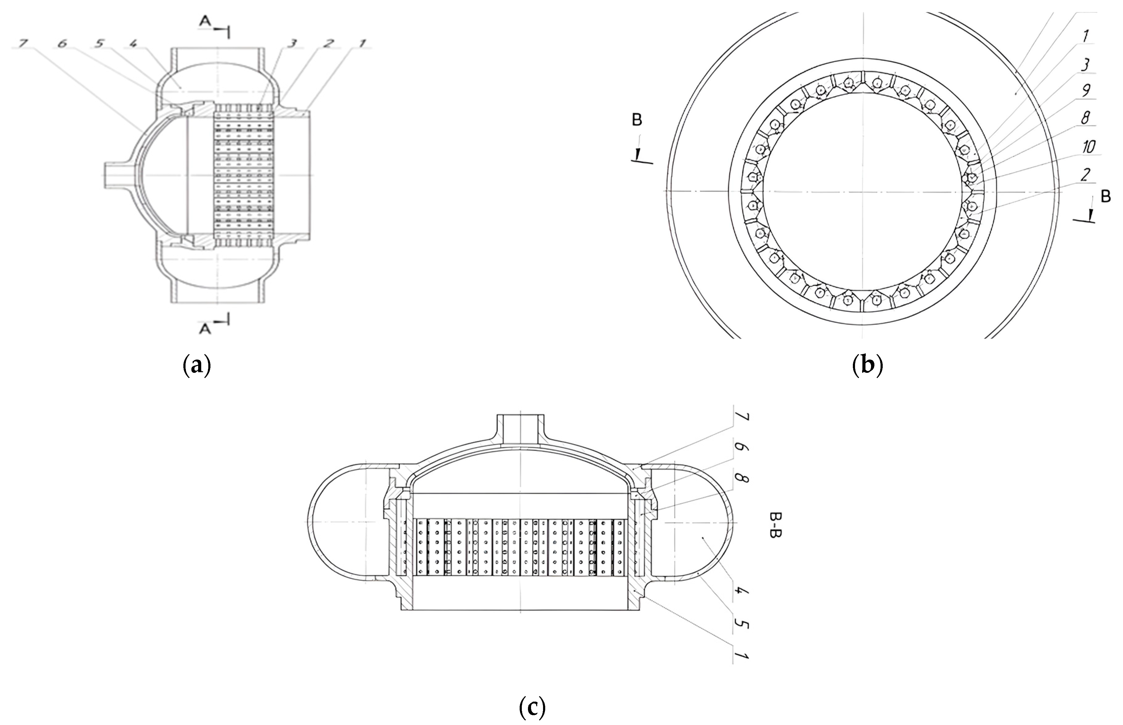
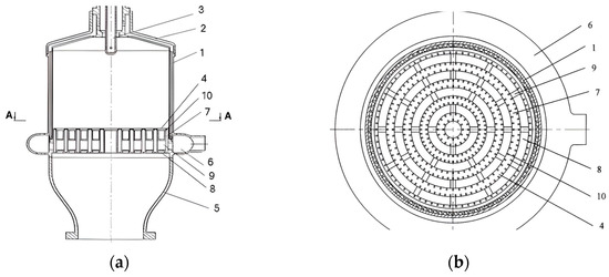
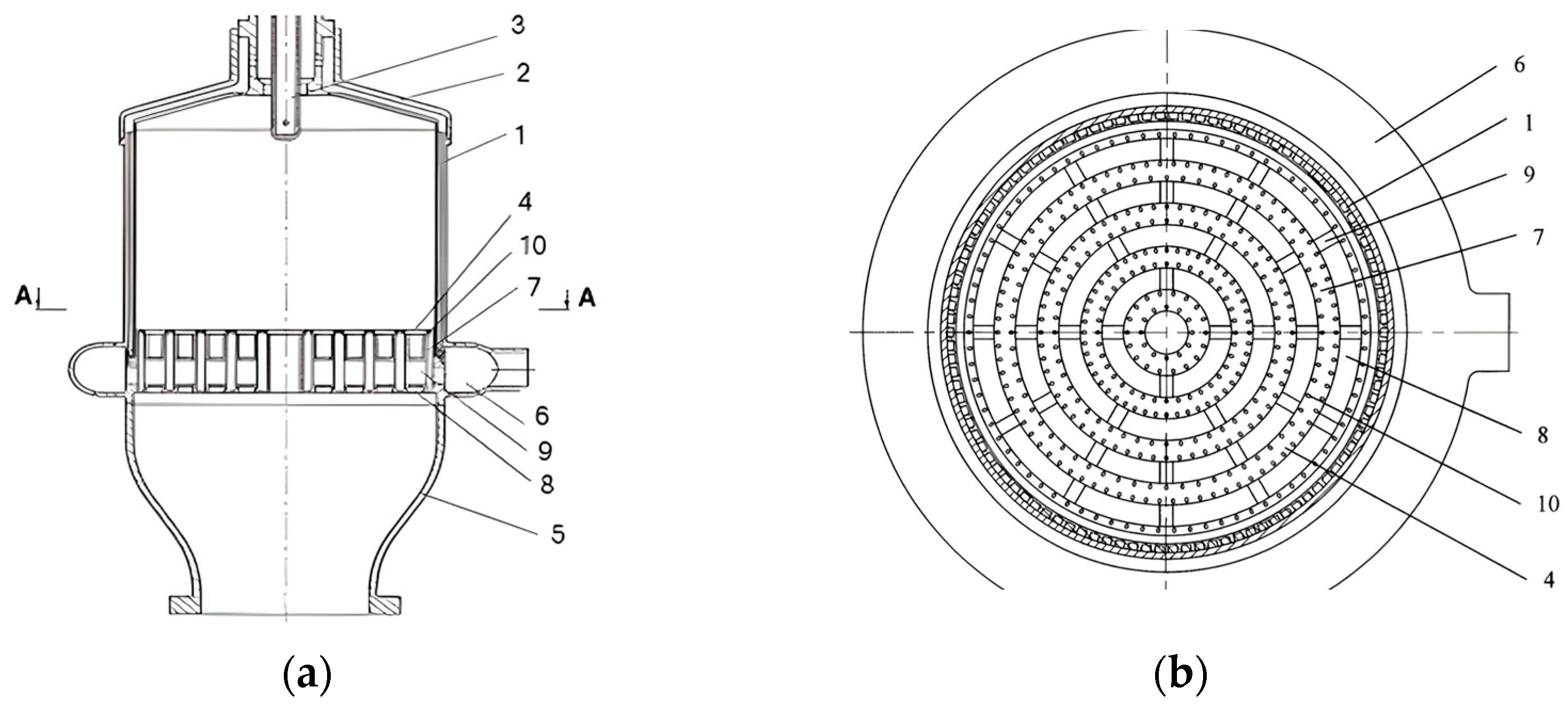
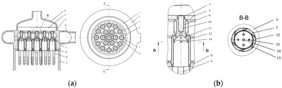

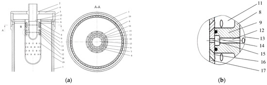
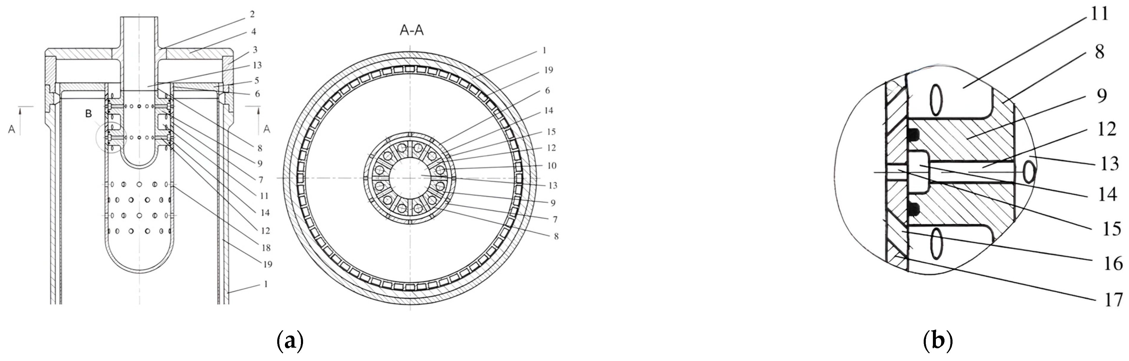
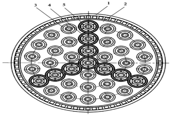
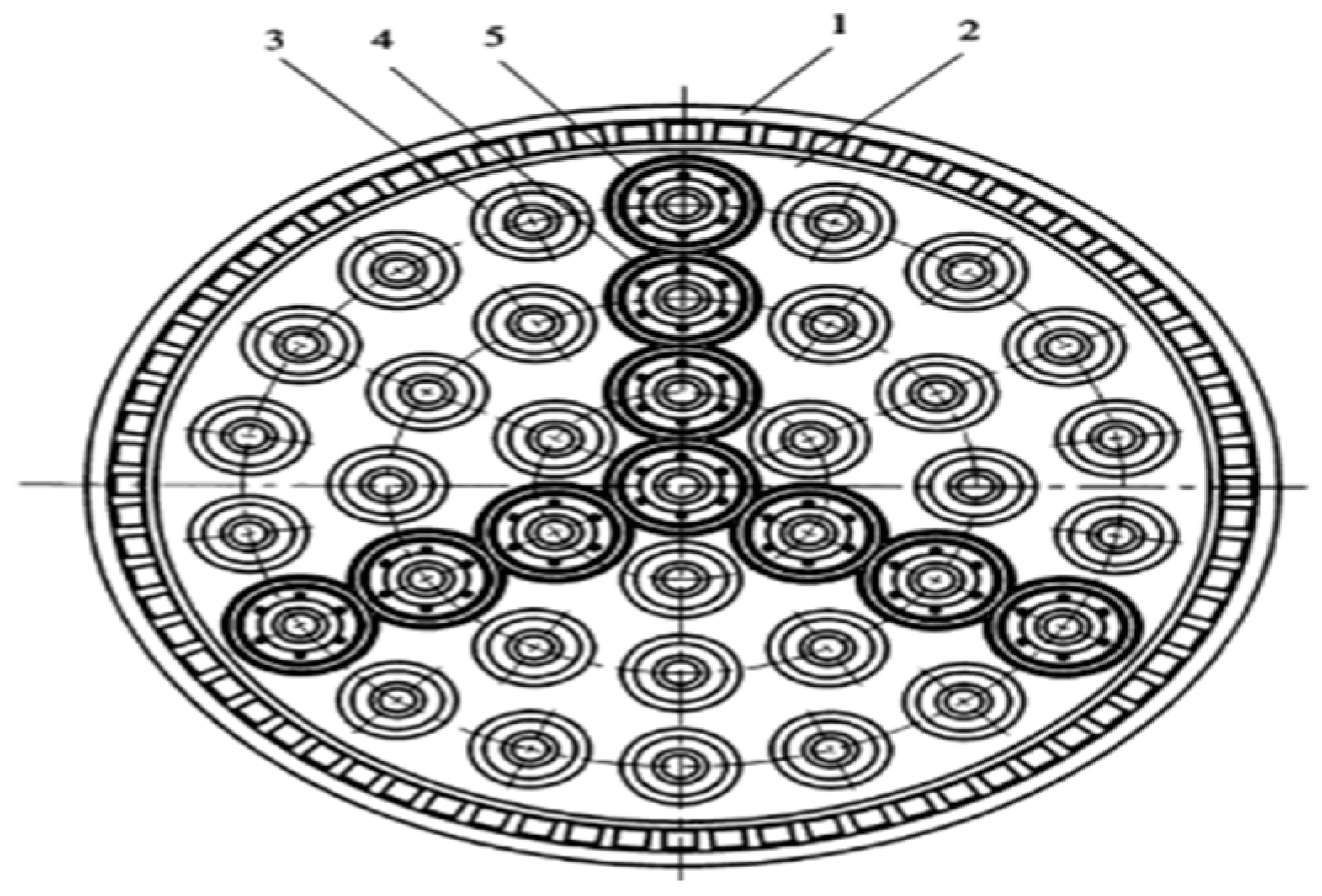
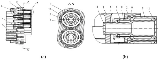
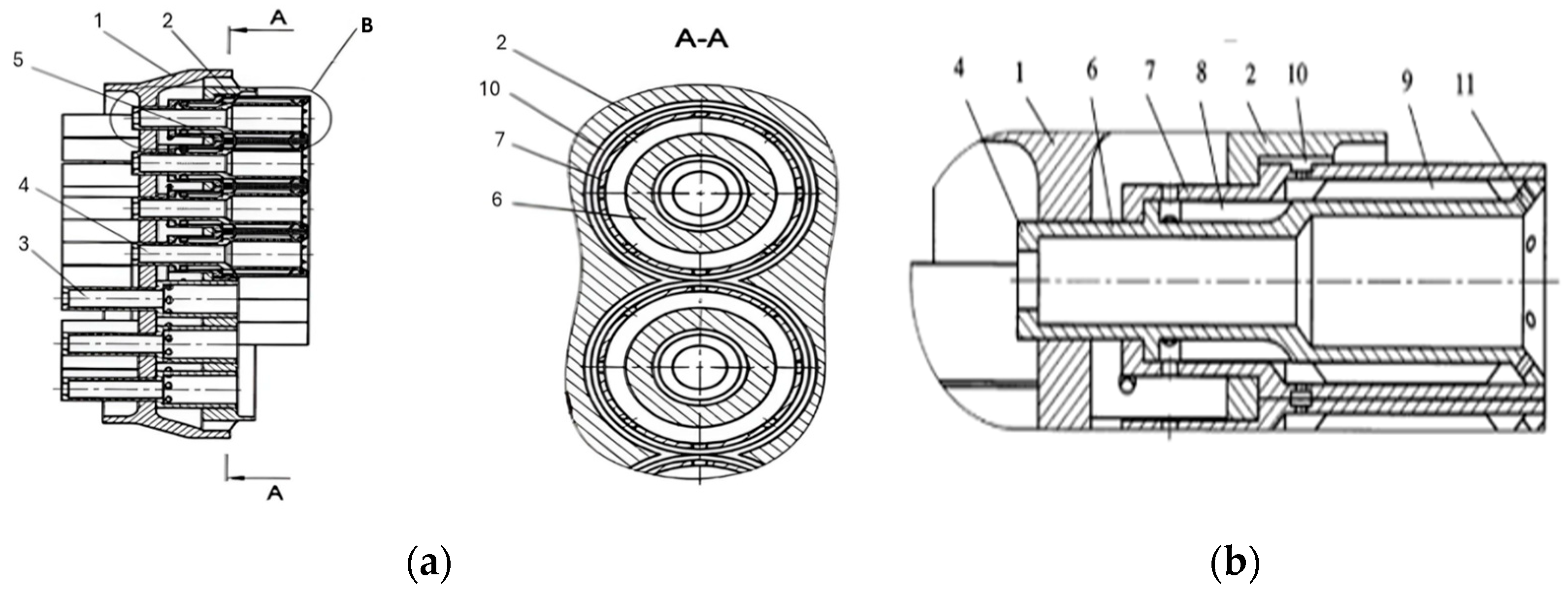
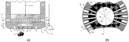
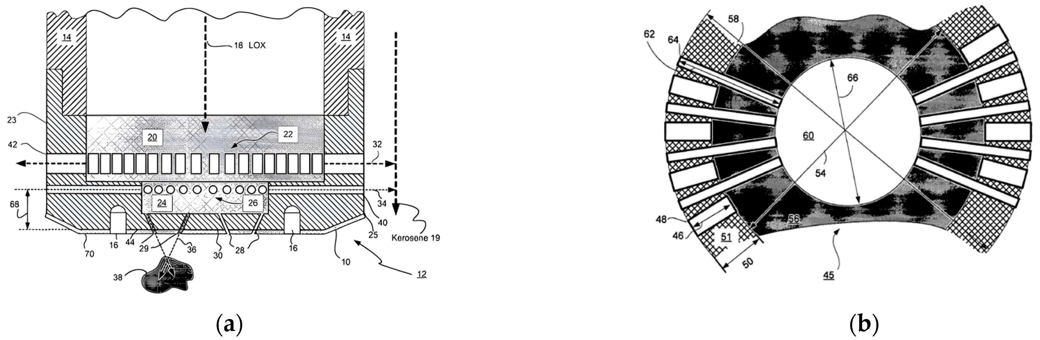
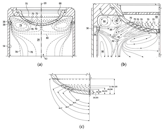
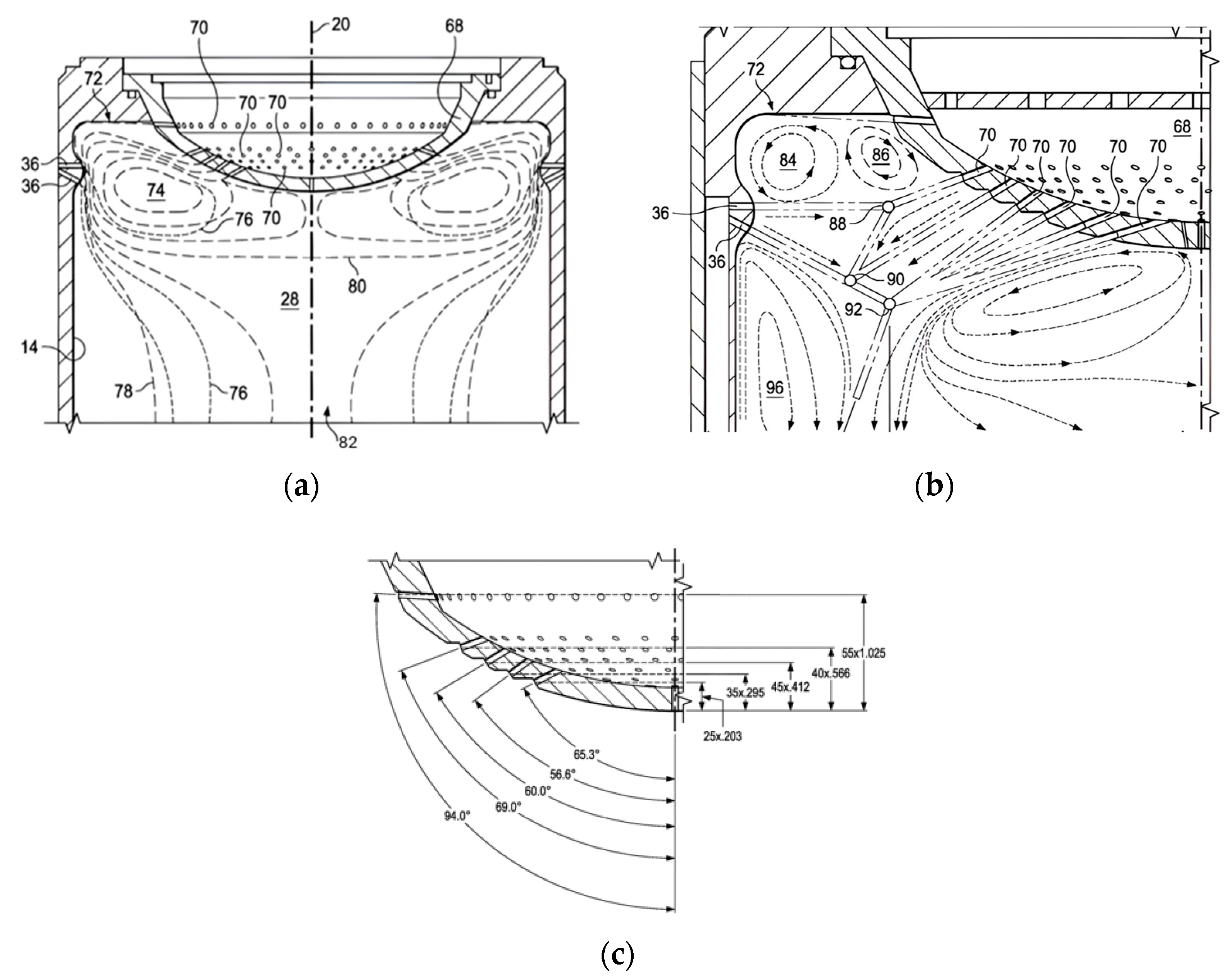
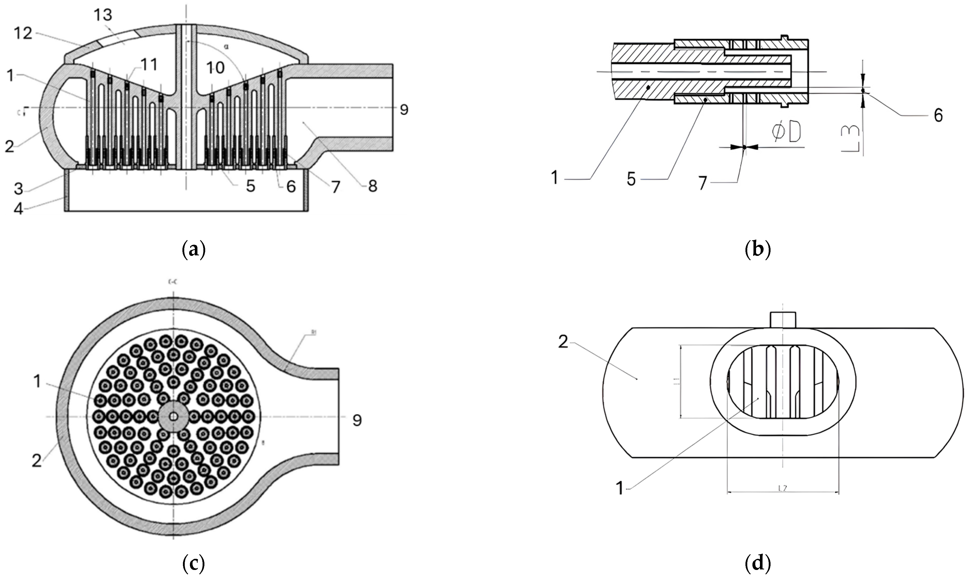
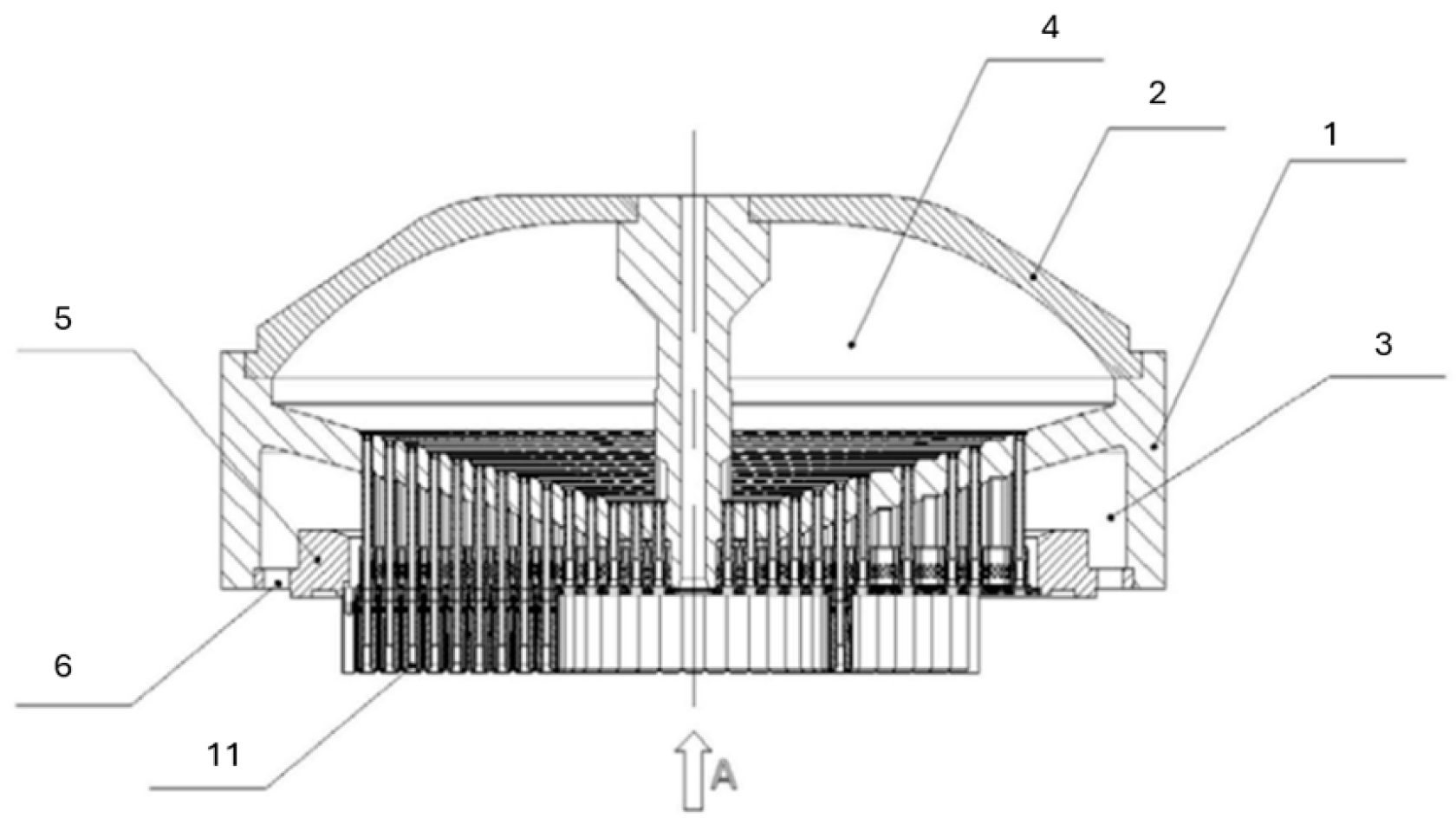
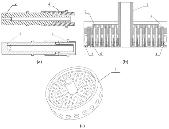
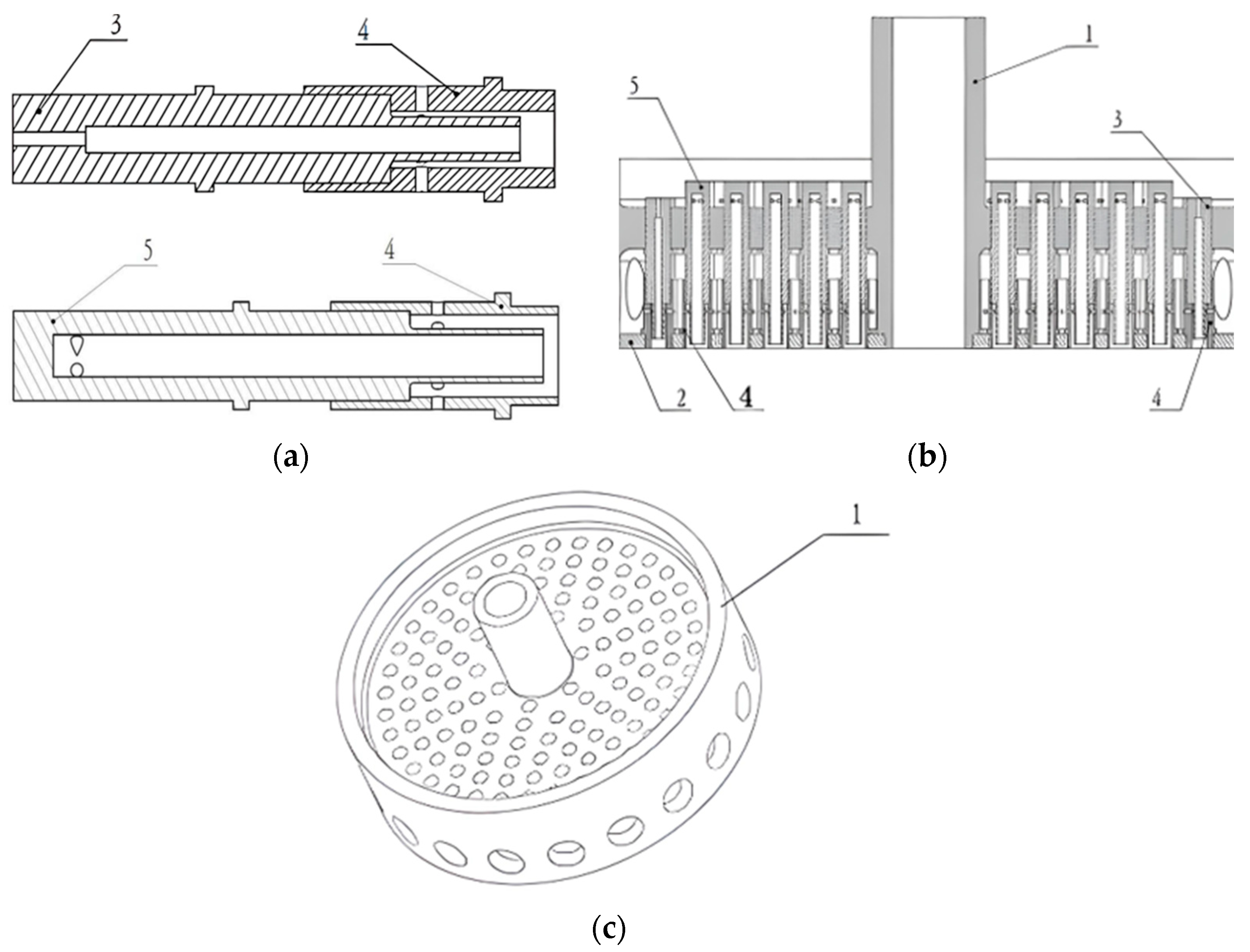
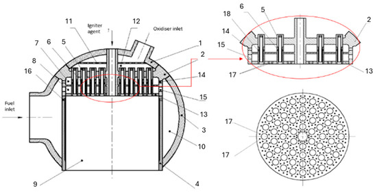
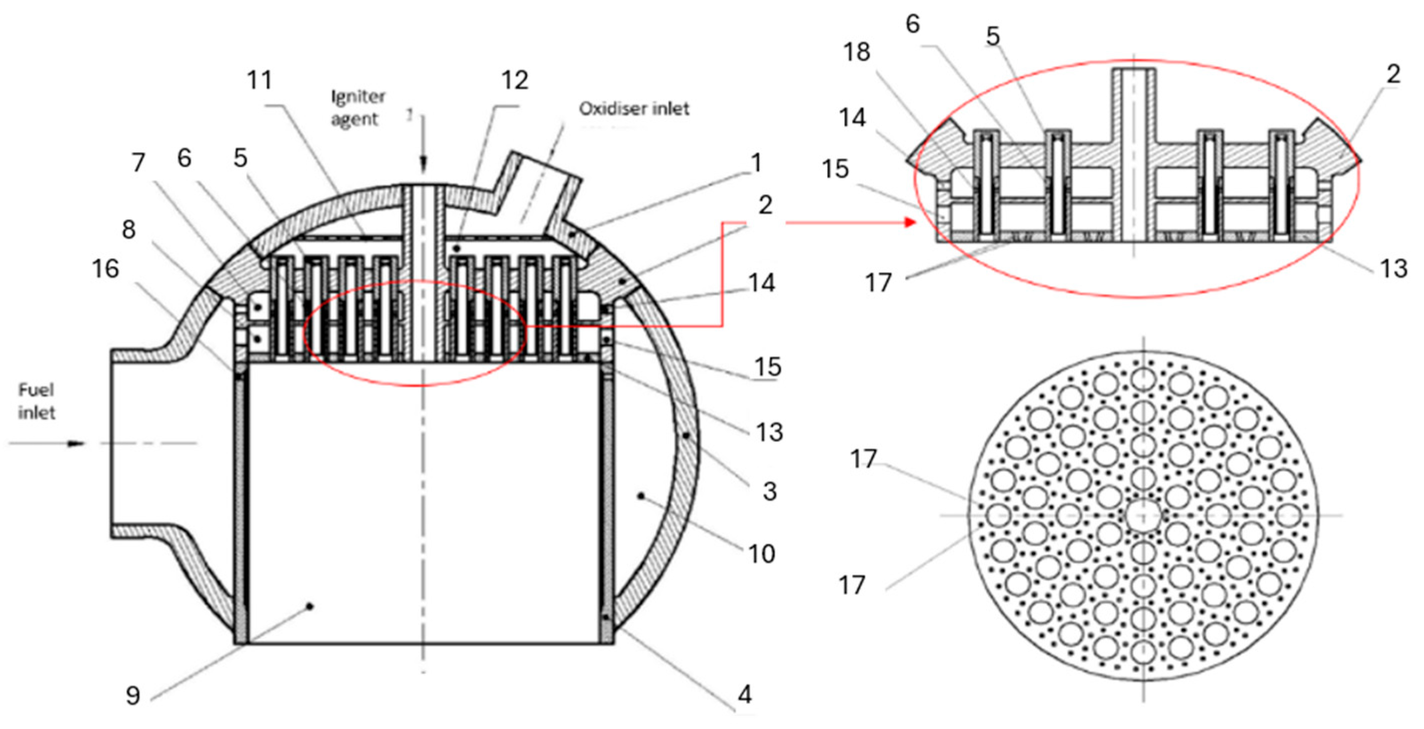
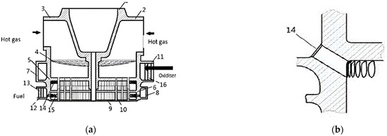
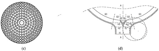
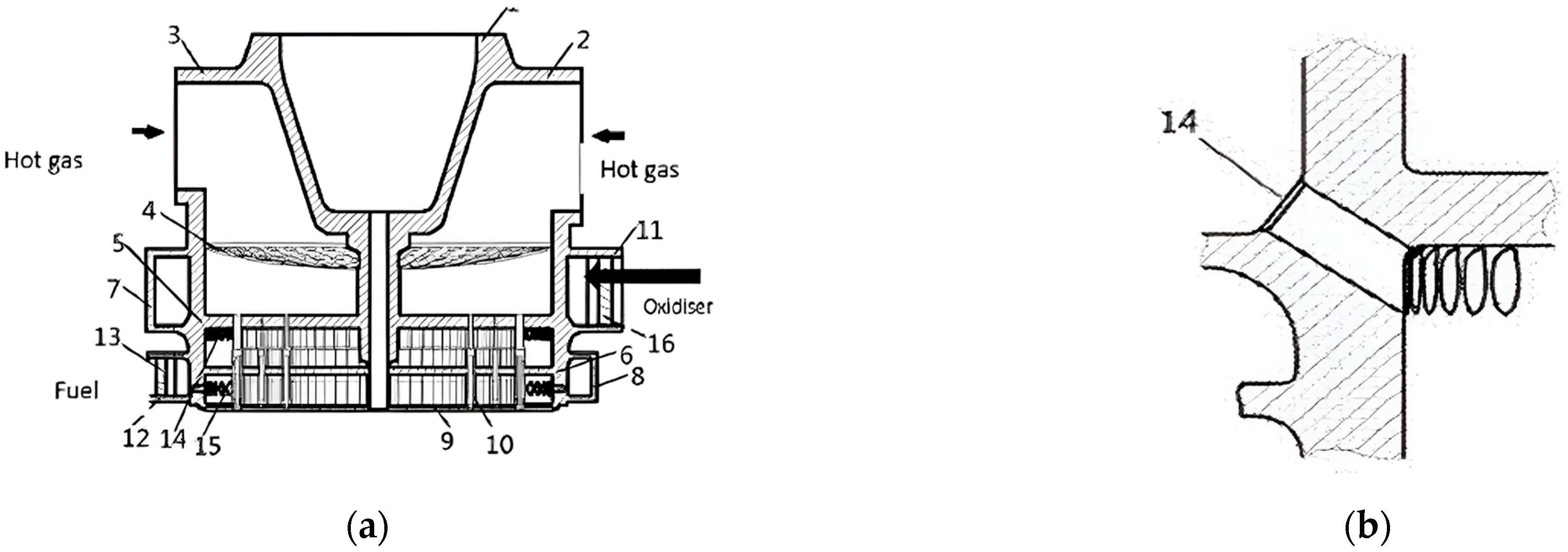
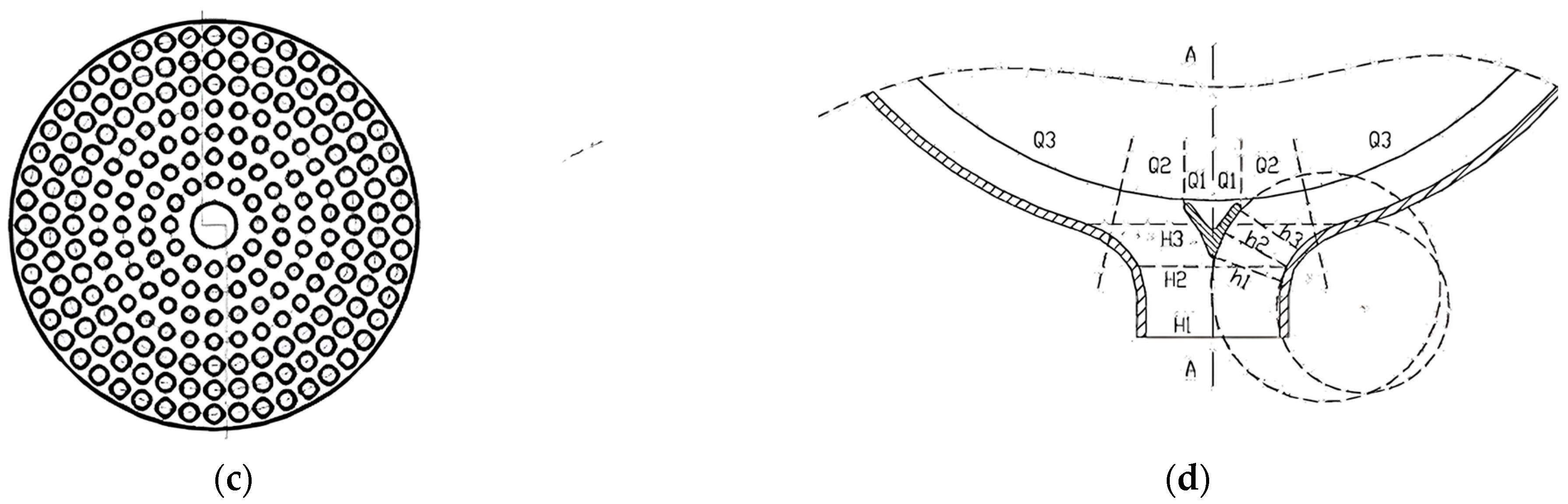
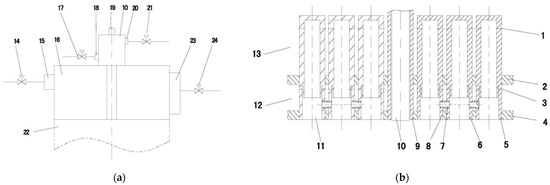
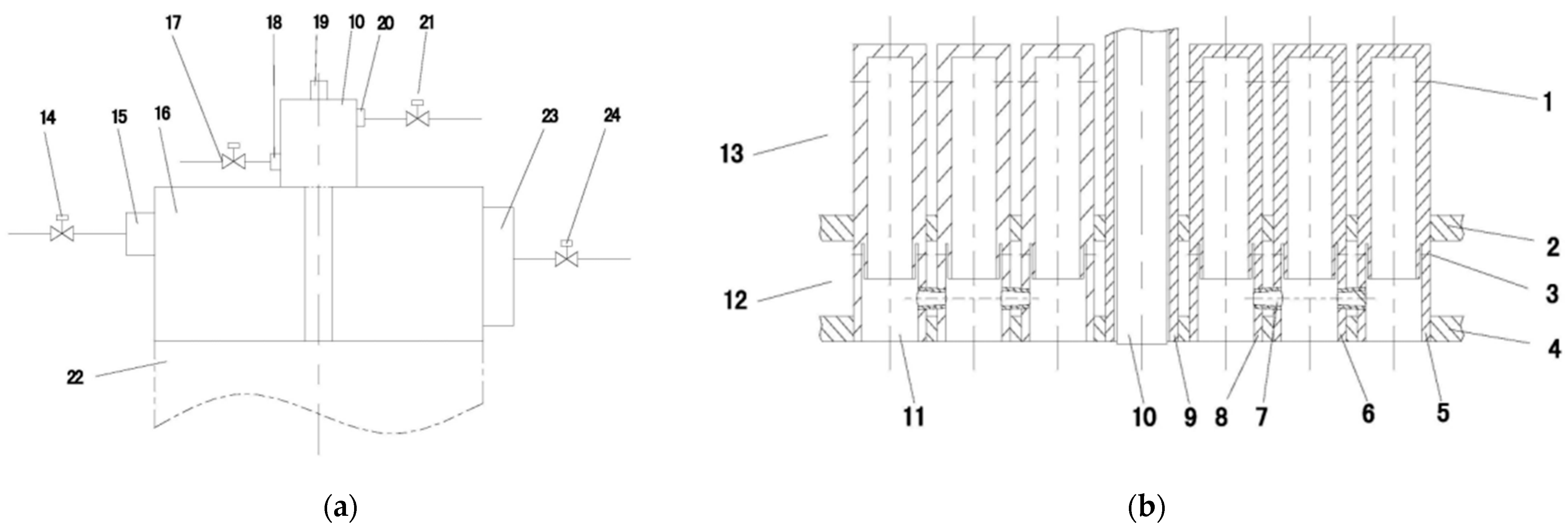
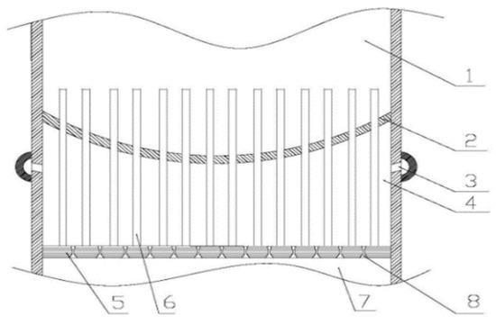
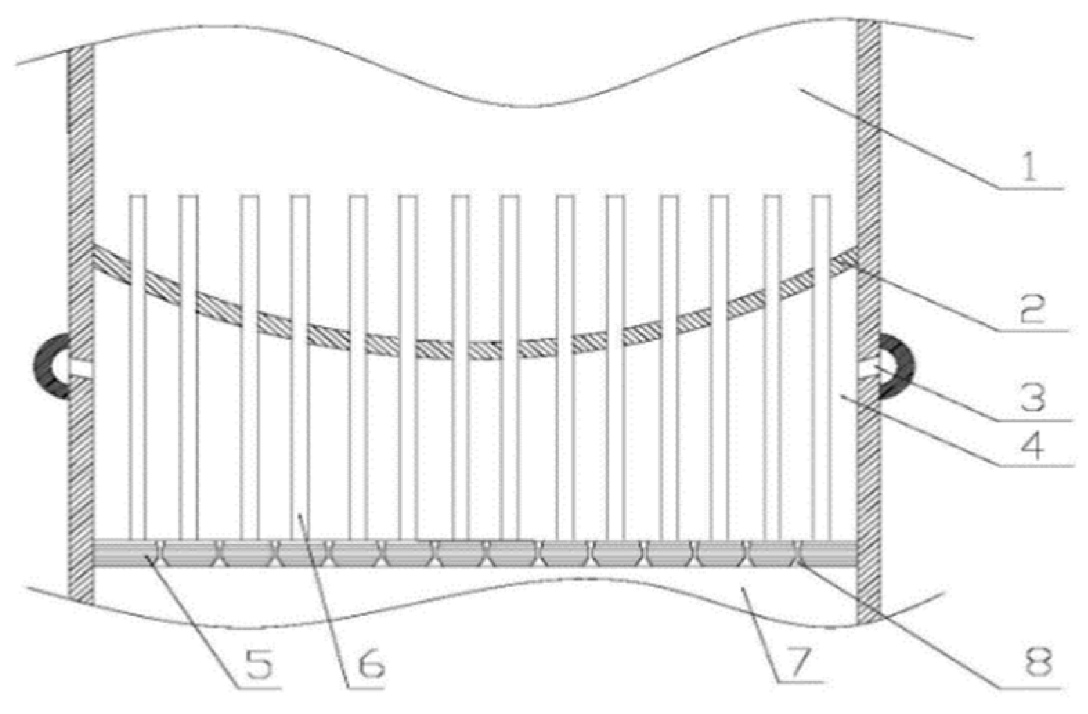
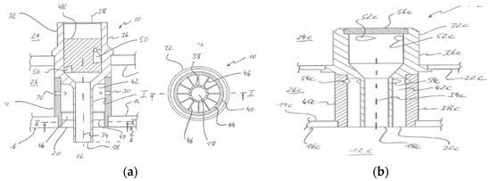
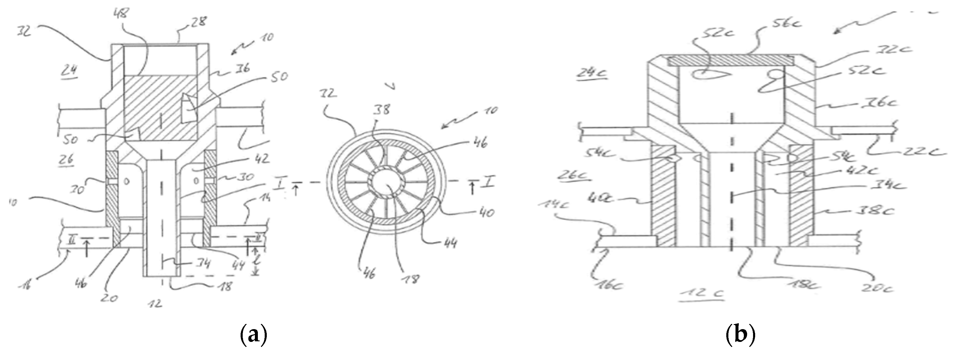
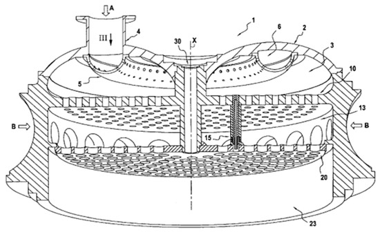
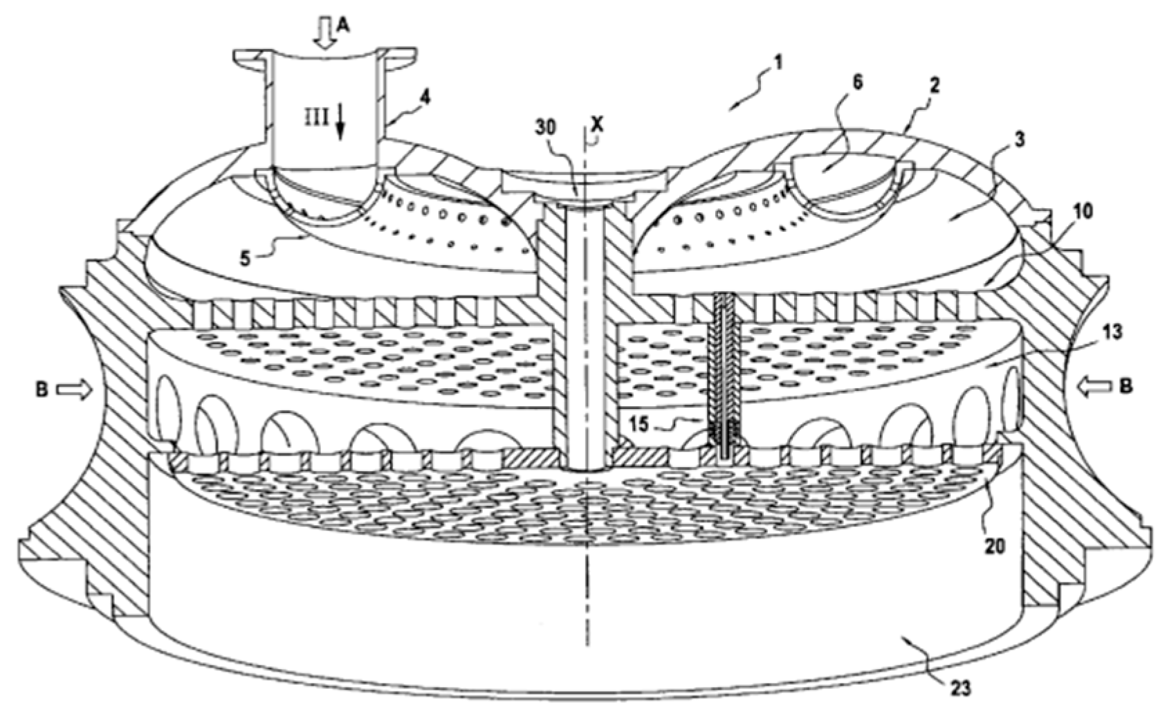
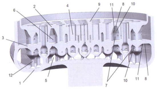
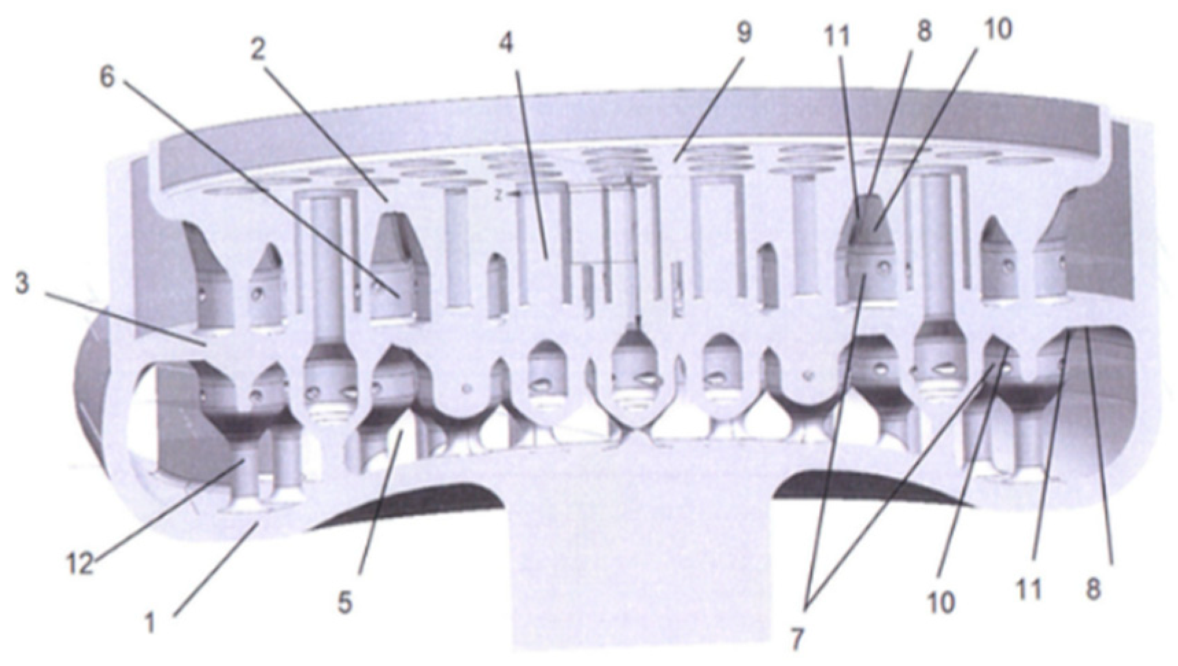
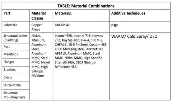
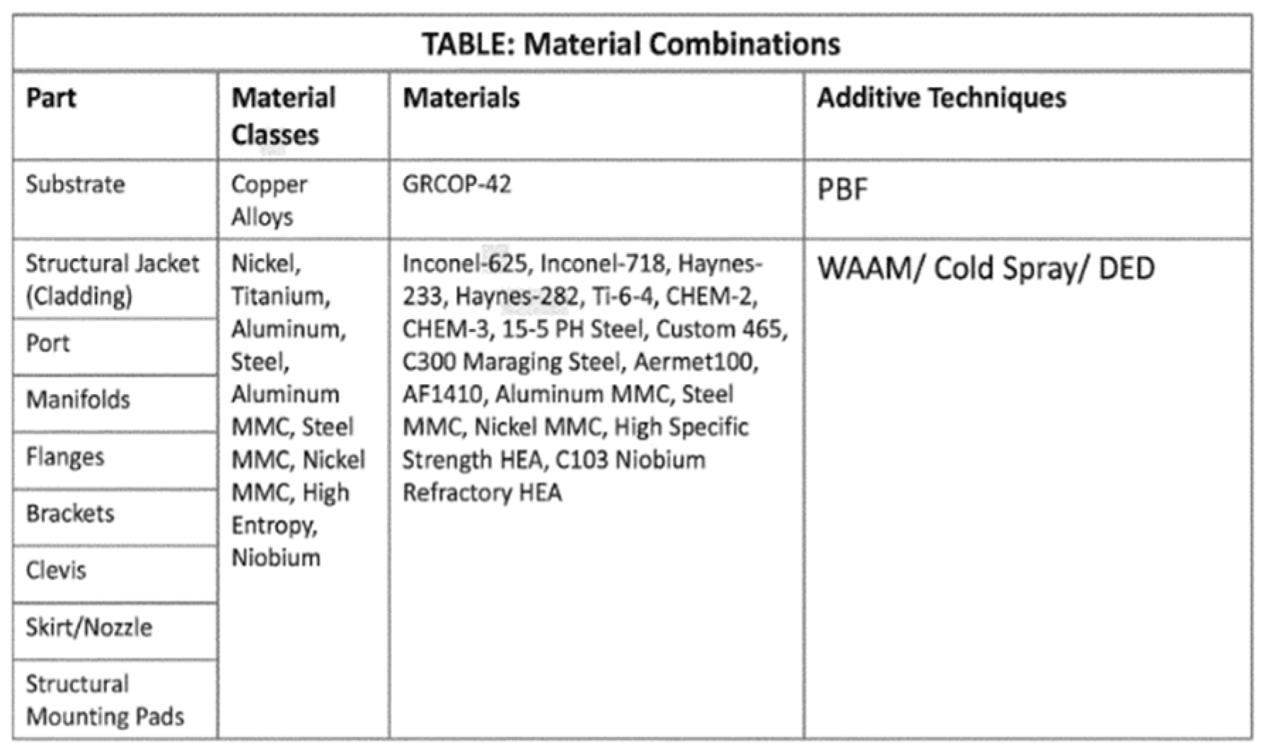
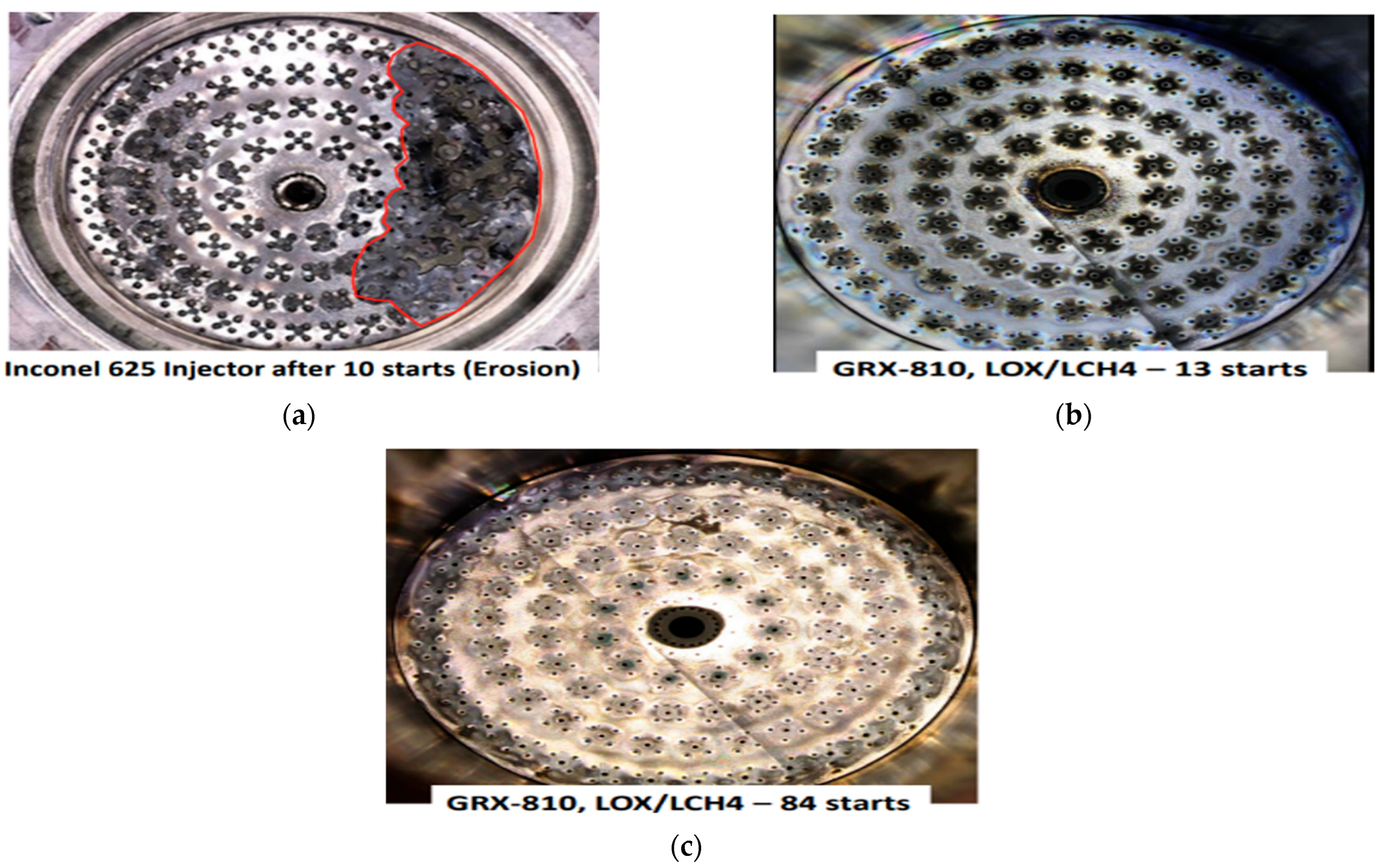

Disclaimer/Publisher’s Note: The statements, opinions and data contained in all publications are solely those of the individual author(s) and contributor(s) and not of MDPI and/or the editor(s). MDPI and/or the editor(s) disclaim responsibility for any injury to people or property resulting from any ideas, methods, instructions or products referred to in the content. |
© 2026 by the authors. Licensee MDPI, Basel, Switzerland. This article is an open access article distributed under the terms and conditions of the Creative Commons Attribution (CC BY) license.