


Abstract
As hypersonic aircraft applications become increasingly extreme, traditional regenerative cooling channels primarily using high-temperature alloys as wall materials can no longer simultaneously meet the dual requirements of thermal protection and lightweight design. This study, based on hypersonic environments with Mach numbers exceeding 8, selects five materials with significant advantages from metals, ceramics, and C/SiC composite materials to conduct a coupled design of wall materials for the flow and heat transfer characteristics of n-decane under 3 MPa pressure. The results show that the heat transfer ability of different material combination schemes is closely related to the thermal–physical properties of the materials, and the materials with obvious advantages in specific thermal–physical properties are dominant. Under a heat flux of 1.5 MW/m2, the GH3128 + Cu composite scheme demonstrates a 17.5% increase in Nusselt number and a 17.6% improvement in comprehensive heat transfer coefficient compared to the traditional high-temperature alloy scheme. When the heat flux triples to 4.5 MW/m2, the temperature variation of the GH3128 + Cu composite scheme is only 50% of that of the steel + C/SiC composite scheme. This indicates that multi-material coupling exerts both synergistic effects and inhibitory effects on flow and heat transfer characteristics, highlighting the importance of flexible material selection tailored to different tactical and technical requirements.
1. Introduction
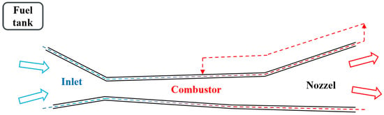
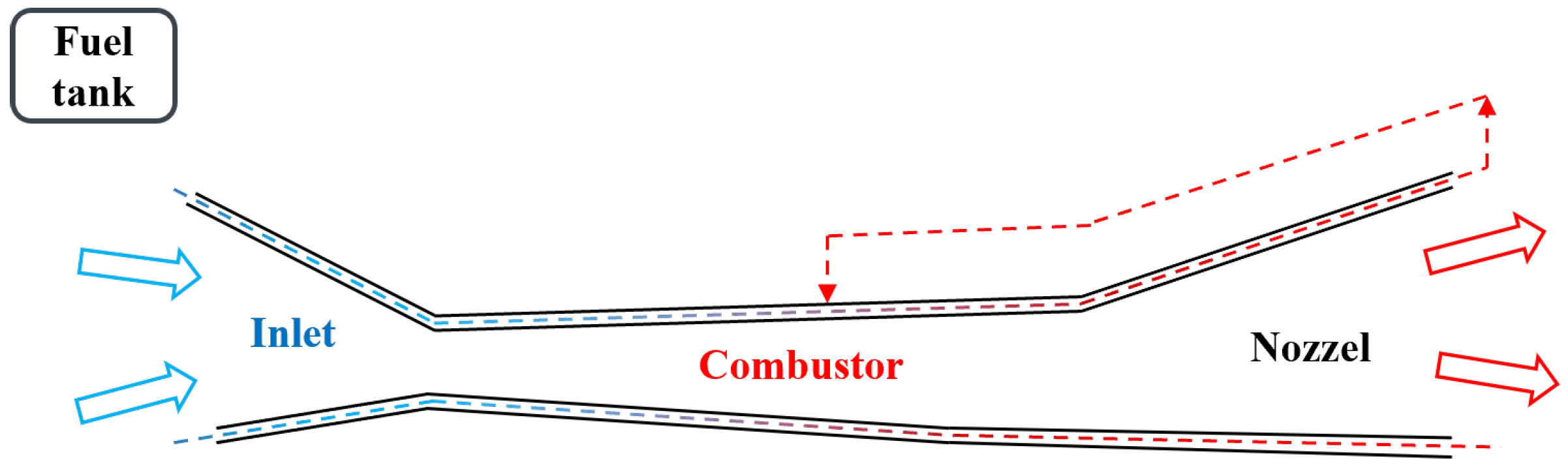
With the progress and development of science and technology in the aerospace field, the performance requirements for hypersonic vehicles are increasingly stringent, making their operating environment more and more harsh. To ensure the normal operation of hypersonic vehicles at high Mach numbers (Ma>8) [1], the scramjet engine, as its core power system, bears thermal protection pressure from both the excessively high total temperature of incoming gas and internal combustion heat release [2]. During long-term flight, it continuously accumulates heat, endures extreme thermal environments [3,4], and faces the dual challenges of improving thermal protection capability and achieving a lightweight design. When the flight speed exceeds Mach 8, the total temperature of the engine inlet air reaches 2500–3000 K, and the inner wall temperature of the combustion chamber can reach 3000–4000 K without cooling [5], which is far beyond the allowable temperature limit of commonly used engineering materials. Therefore, it is necessary to adopt cooling methods to reduce heat accumulation on the combustion chamber wall during heat transfer, keep the wall temperature below the material melting point, and find engineering materials with better physical properties and high-efficiency coolants to meet the highly harsh flight environment. At present, scholars at home and abroad have carried out a large number of studies and experiments on active cooling (including regenerative cooling, film cooling, transpiration cooling, etc.) and achieved a series of important milestones. Existing research results show that regenerative cooling technology has a wider application range and better development prospects than other cooling methods [3,6,7,8]. As show in Figure 1, regenerative cooling means that low-temperature fuel flows through the cooling channels built in the high-temperature wall of the engine before entering the combustion chamber to participate in combustion. On the one hand, the coolant can absorb a large amount of heat and then directly participate in combustion, making full use of the originally wasted heat, realizing “regenerative” utilization of energy, and taking into account both cooling and energy recovery. On the other hand, it avoids the additional load burden caused by carrying extra coolants and supporting heat exchange equipment, achieving lightweight design of the vehicle. Aviation kerosene is an aircraft fuel with a complete technical system and mature application. It has the advantages of high energy density, low volatility, thermal stability and safety, and adaptation to stable storage and transportation and preliminary liquefaction under high-altitude, low-temperature, and low-pressure environments, and it can ensure the safe and stable operation of regenerative cooling for hypersonic vehicle engines. The thermophysical properties of aviation kerosene under supercritical conditions are the research foundation of regenerative cooling technology. It can provide a larger volumetric heat sink in a limited fuel storage space, and the cooling capacity per unit space is better [9,10,11,12,13]. High-temperature degradation is one of the key problems restricting the development of regenerative cooling technology. Existing studies have optimized the effects on n-decane pyrolysis and coking mechanisms through methods such as catalytic steam reforming [14], using aluminum nanoparticles [15,16], adding hydroxyl-containing additives [17], and adjusting dissolved oxygen concentrations [18]. The cooling performance of a regenerative cooling system is determined by the properties of the coolant, the design of the channel structure, and the thermal protection materials. Current research on channel structures is extensive, with cross-sectional shapes such as circular, rectangular, U-shaped, triangular, and wavy [19,20,21]; geometric parameters like channel dimensions, wall thickness, or rib thickness [22,23,24]; and flow parameters (mass flow rate, inlet temperature, secondary flow) [25,26,27,28], and header-related designs [29,30] all proven to significantly affect flow and heat transfer characteristics. Rectangular channels have the widest engineering applicability due to their ease of manufacturing and high space utilization [19,21]. Micro-rib structures (V-shaped, crescent-shaped, boot-shaped) [23,24,31,32] and topology optimization [21] can effectively enhance turbulent mixing and improve heat transfer efficiency. Flow phenomena, such as buoyancy effects, flow oscillations, and boundary effects [27,28], can also lead to deteriorated heat transfer. The selection of the optimal channel design must be customized based on the actual application scenario of the engine (Mach number, heat flux density distribution, structural constraints) [19,21,22]. Most existing channel design studies focus only on the fluid side or structural optimization itself, neglecting the coupling effect between the thermophysical properties of the wall material and the flow and heat transfer characteristics of the channel [33,34]. With the development of advanced composite materials, carbon fiber-reinforced ceramic matrix composites (CMCs), owing to their high strength, low density, low coefficient of thermal expansion, and high thermal stability, have become a research hotspot for regenerative cooling thermal protection [33]. Xin et al. studied the influence of the proportion of C/SiC composites in the structure and the anisotropy of thermal conductivity of C/SiC composites on the thermal protection capability of the regenerative cooling structure. Different schemes show that C/SiC composites significantly improve the structural weight reduction capacity and avoid heat transfer deterioration [34]. A ADAMI et al. studied how to maintain the good propulsion performance of bipropellant engines; proposed a combined cooling scheme of ablative cooling and radiative cooling; and selected graphite, aluminized zinc steel plates, and TPS materials to form a composite thermal protection layer to ensure that the wall temperature is below the material melting point, improving thermal protection performance and structural lightweight [35,36,37,38,39].
Figure 1.
Schematic diagram of regenerative cooling channels.
Through a literature review, it was found that although composite materials hold great potential in the selection of thermal protection materials, there are still key research gaps. For example, the stability and reliability of different material combinations under varying thermal environments have not been sufficiently validated, the impact of material property degradation under long-term high-temperature loads on the overall performance of regenerative cooling structures remains unclear, and the synergistic and inhibitory effects of multi-material coupling on flow and heat transfer characteristics lack analysis. To address these research gaps, this study selects five representative engineering materials (GH3128, C/SiC, Cu, steel, ZrO2) based on practical manufacturability and thermal–physical performance advantages, covering metal, ceramic, and composite categories. Six rectangular regenerative cooling channel wall material combination schemes are designed. Numerical simulations are conducted at 3 MPa pressure to investigate the temperature distribution of the channel walls and the flow and heat transfer characteristics of supercritical n-decane. Quantitative analysis is performed on key performance parameters, such as comprehensive heat transfer coefficient, Fanning friction factor, dimensionless entropy generation number, and overall heat transfer performance, to compare the thermal protection capabilities of different material combinations. Additionally, three material combination schemes with different heat transfer effects are selected for performance comparison under varying heat fluxes (1.5–4.5 MW/m2) to further verify the reliability of these material combinations under different environments. This study aims to identify optimized material combination schemes with enhanced heat transfer performance, clarify the advantages and disadvantages of different schemes under various tactical and technical requirements, and provide a theoretical basis for the material selection and coupled design of regenerative cooling structures in hypersonic vehicles.
2. Numerical Methods and Model Validation
2.1. Calculation Domain and Parameter Settings
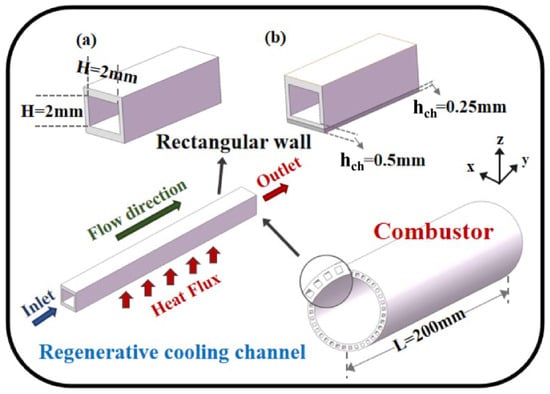
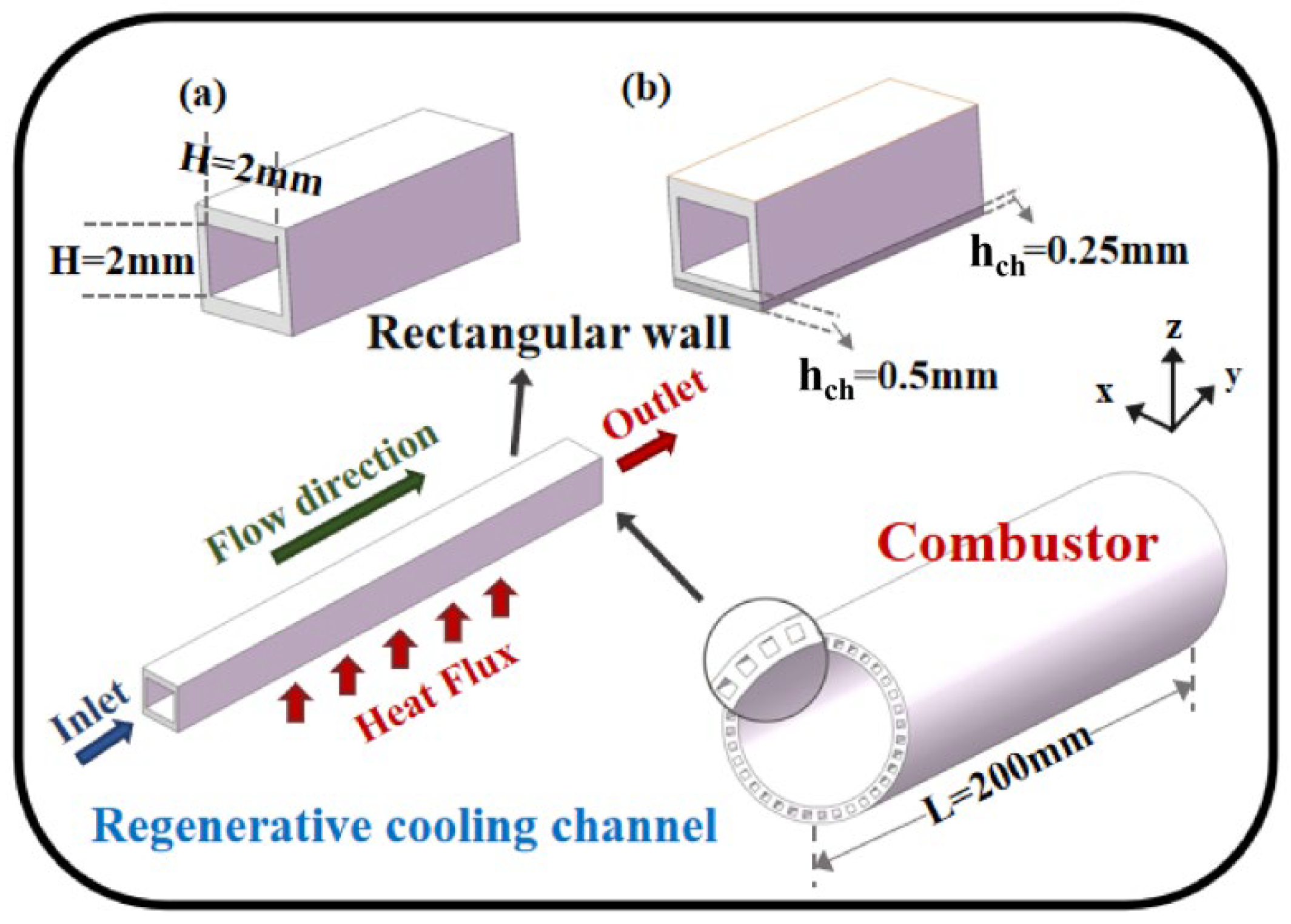
The dimensions of the regenerative cooling channels are much smaller compared to the combustion chamber and are arranged in a circle. As shown in Figure 2, an ideal combustion chamber channel model typically exhibits structural symmetry, so one of the single regenerative cooling channels is selected as the research object in this study to analyze its flow and heat transfer characteristics.
Figure 2.
Model calculation domain. (a) Single material channel. (b) Combined material channel.
The regenerative cooling channel adopts a rectangular straight channel, with detailed structural parameters as follows: The total length of the channel is 200 mm, with a heating section length of 150 mm. To ensure normal fluid velocity when entering the heating section and guarantee heat exchange efficiency, there are 25 mm adiabatic sections at both the front and rear. The hydraulic diameter of actual regenerative cooling channels ranges from 0.3 to 4 mm. In this model, the fluid domain is set as a 2 mm × 2 mm square, with flow along the x-axis; the gravitational acceleration direction is along the negative y-axis. Based on symmetry, the thickness of the solid domain is set to 0.5 mm along the y-axis and 0.25 mm along the z-axis. For the paired structural combinations, the wall located below the fluid domain along the y-axis is divided into two layers, with each material thickness being 0.25 mm. The overall calculation domain is 3 mm × 2.5 mm, and the bottom surface is the heated wall of the channel.
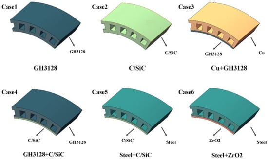
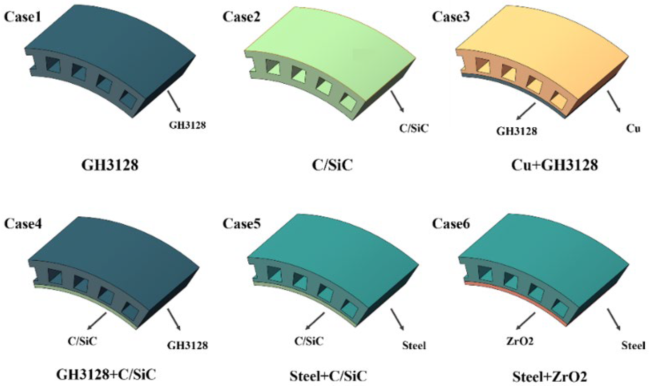
This paper focuses on the influence of two key variables, wall material combination and heat flux size, on the regenerative cooling channel. Among them, Cases 1–6 are about different combination schemes of five materials (Case 1 is a single superalloy material, which serves as the reference control group), and the three groups of combination schemes with obvious differences in heat transfer effect are selected to change the heat flux size, and the regenerative cooling effect is further compared and analyzed. The specific case settings and parameters are shown in Table 1. Figure 3 provides an intuitive presentation of the structure of the regenerative cooling channel.
Table 1.
Case settings and related parameters.
Figure 3.
Schematic diagram of different material combination schemes.
2.2. Thermal–Physical Properties of Coolant
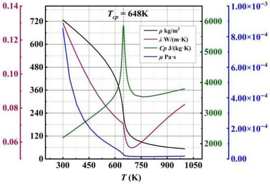
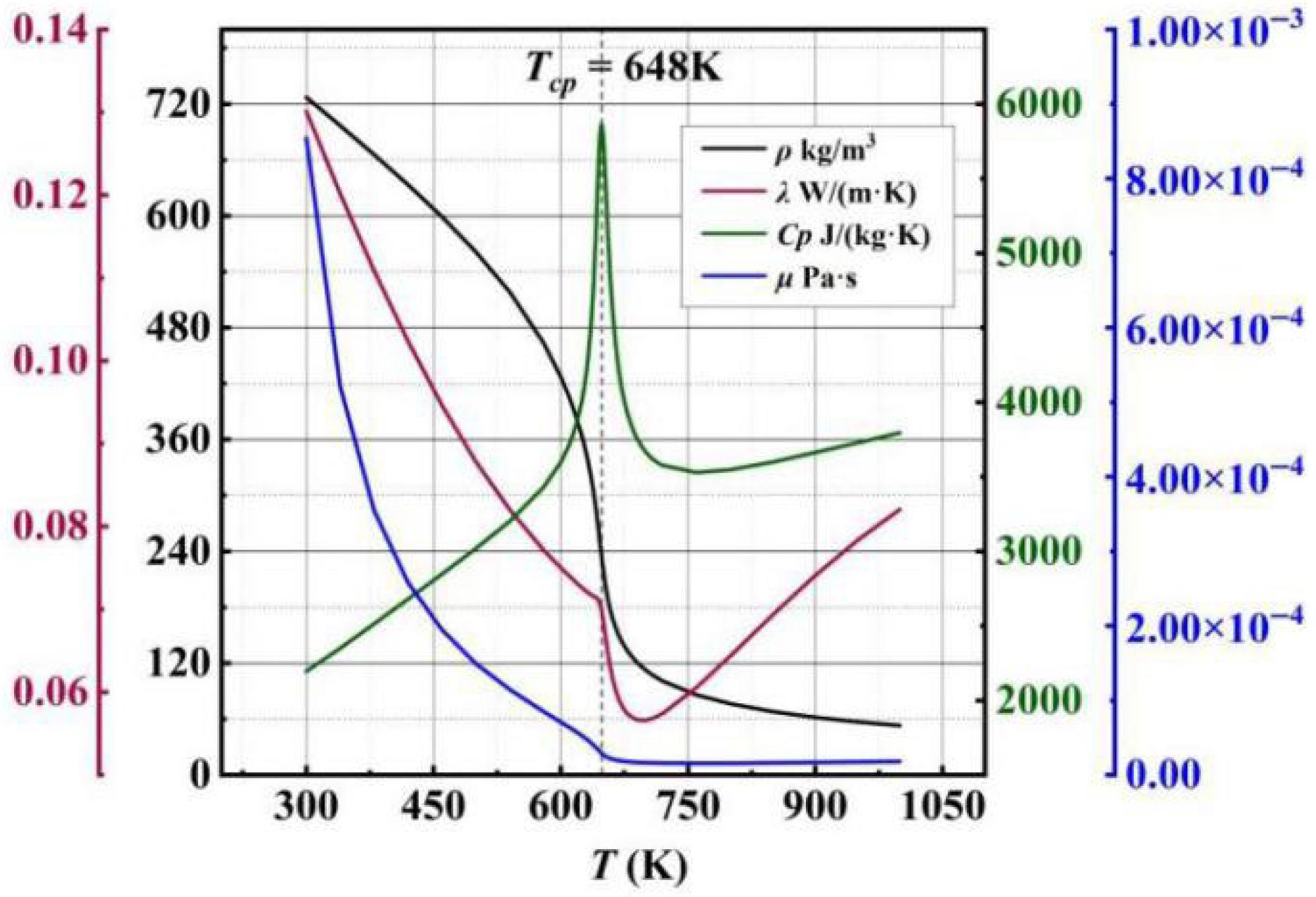
As temperature increases, the thermophysical properties of aviation kerosene change significantly. To accurately capture the optimal operating range of this coolant, SUPERTRAPP software, developed by the National Institute of Standards and Technology (NIST), is employed to obtain a series of physical data for the single coolant n-decane at 3 MPa, including specific heat capacity, density, dynamic viscosity, and thermal conductivity. Accurate graphs illustrating the variation of each physical property with temperature are generated by means of Origin 2018 software, and the critical temperature is selected as TCp = 648 K. The thermophysical data of n-decane are imported into the material library of Fluent 2022 R1 software, ensuring that the simulation accurately leverages the excellent cooling capacity and supercritical physical state of n-decane under specific high-temperature conditions so as to optimize the regenerative cooling process. Figure 4 shows the thermophysical properties of n-decane. In this study, the inlet pressure of the fluid is fixed at 3 MPa, which is higher than the critical pressure of n-decane. Therefore, the “supercritical state” mentioned in subsequent discussions specifically refers to the “supercritical temperature state”, i.e., the state where significant abrupt changes occur in the thermophysical properties of the fluid.
Figure 4.
Variations of thermophysical properties of n-decane with temperature at a pressure of 3 MPa.
2.3. Thermal–Physical Properties of Materials
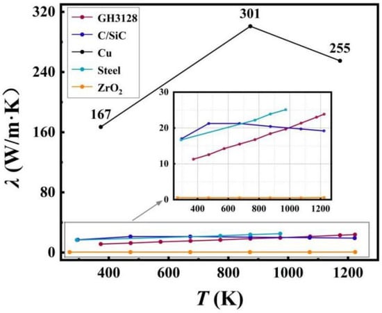
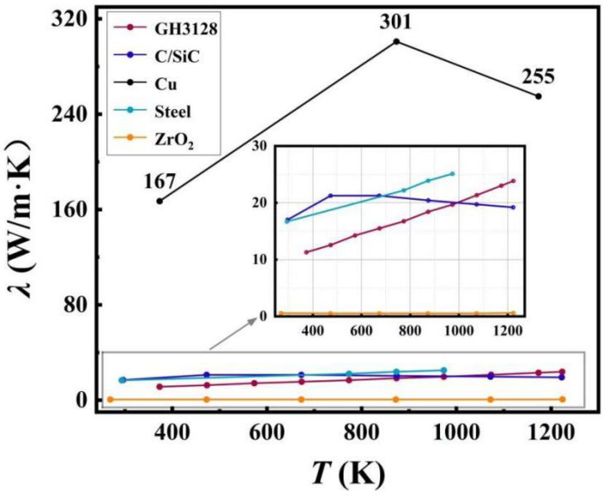
The internal combustion environment of hypersonic vehicle engines is extremely harsh. Channel materials must meet the core requirements of high-temperature resistance and lightweight design at the same time, but their key properties, such as strength, stiffness, and thermal conductivity, often constrain each other, which affects overall optimization. This study focuses on the influence of different wall materials on the overall flow and heat transfer characteristics of regenerative cooling channels. Five representative engineering materials are selected, including GH3128 superalloy, C/SiC ceramic matrix composite, chromium bronze, stainless steel, and ZrO2 ceramic, hereinafter referred to as GH3128, C/SiC, Cu, steel, and ZrO2. These materials cover three major categories—metals, ceramics, and composites—and their key physical properties, such as density, specific heat capacity, and thermal conductivity, vary significantly with temperature. Table 2 and Figure 5 shows the thermophysical parameters of these five materials. The five selected materials have complementary thermophysical properties (e.g., high thermal conductivity, lightweight, thermal insulation) and mature engineering applicability, ensuring comprehensive exploration of material combination effects on regenerative cooling.
Table 2.
Thermophysical parameters of materials.
Figure 5.
The distribution of thermal conductivity of materials with temperature.
GH3128 has excellent strength and stiffness at high temperatures, along with high toughness and good fatigue resistance. It can be processed into various ideal shapes, directly withstand the pressure and impact generated by coolant flow, and has no special requirements on wall thickness. Its thermal conductivity is at a moderate level, but it is not conducive to lightweight design. C/SiC has advantages in lightweight design and heat storage, with strong structural stability at high temperatures, but its thermal conductivity is relatively moderate. Due to high brittleness, it has insufficient impact and deformation resistance, making processing and forming difficult. The core advantage of Cu lies in ultra-high thermal conductivity, which ensures outstanding heat transfer efficiency. It also has good ductility and easy processability, but its mechanical properties degrade at high temperatures, resulting in insufficient strength and stiffness. It shares similar lightweight limitations with GH3128. Steel is cost-effective with mature manufacturing processes, stable mechanical properties, and easy processability, which can meet the structural bearing requirements under conventional working conditions, but it lacks competitiveness in lightweight and comprehensive heat transfer performance. ZrO2 has stable physical and chemical properties and extremely low thermal conductivity, so it is usually used as a thermal insulation material. It has weak impact and bending resistance and high processing difficulty.
Based on the principle of complementary advantages of different material properties, this study combines materials in pairs by integrating the characteristic advantages of individual materials in heat transfer efficiency, flow resistance control, and structural stability. This approach compensates for the performance shortcomings of single materials in extreme environments. By analyzing the flow and heat transfer characteristics of different material combinations, this study provides theoretical support for the material selection of regenerative cooling channels.
2.4. Solver and Boundary Settings
In the subsequent sections of this paper, the following physical quantities will be adopted to conduct a comprehensive analysis of the heat transfer performance of the channel. The calculation methods and governing equations corresponding to the main physical parameters are presented.
The convective heat transfer coefficient of the channel h is defined as
where q denotes the heat flux of the heated wall, Tw represents the average wall temperature, and Tf represents the average fluid temperature.
The Fanning friction factor f is defined as
where ΔP is the pressure drop, Dh is the hydraulic diameter of the channel, ρ is the fluid density, and u is the fluid velocity.
Heat transfer entropy generation and flow entropy generation quantify the irreversible loss in heat transfer processes and the mechanical energy loss in fluid flow, with their definitions as follows:
The dimensionless entropy generation number Ns1, which quantifies the relative degree of irreversible losses in heat transfer and flow processes, is defined as
The Nusselt number Nu is defined as
The comprehensive heat transfer coefficient of the channel η is defined as
Conservation equations of mass, energy, and momentum:
where ρ is the fluid density, t is the fluid temperature, μ is the fluid viscosity, λ is the thermal conductivity, and E is the modulus of elasticity.
Turbulence model:
where k is the turbulent kinetic energy of the fluid, ω is the vortex frequency (ω = k/l2), and l is the turbulent length scale.
Fluid–structure interaction model
This paper uses Fluent software for numerical simulations. The solver model satisfies the mass, momentum, and energy conservation equations. For the fluid domain and solid domain, the principles of flow continuity and heat conduction equations are, respectively, followed. Through validation, the k-ω SST turbulence model with the best fitting effect is selected. The SIMPLEC algorithm handles the pressure–velocity coupling process, and the second-order upwind scheme (SECOND ORDER UPWIND) discretizes data such as momentum, energy, and turbulent kinetic energy. Residual monitoring ensures that the convergence criteria for continuity, x-velocity, y-velocity, z-velocity, energy, k, and ω are set to 10−6.
2.5. Model Validation and Mesh Independence Test
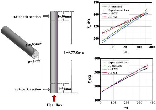
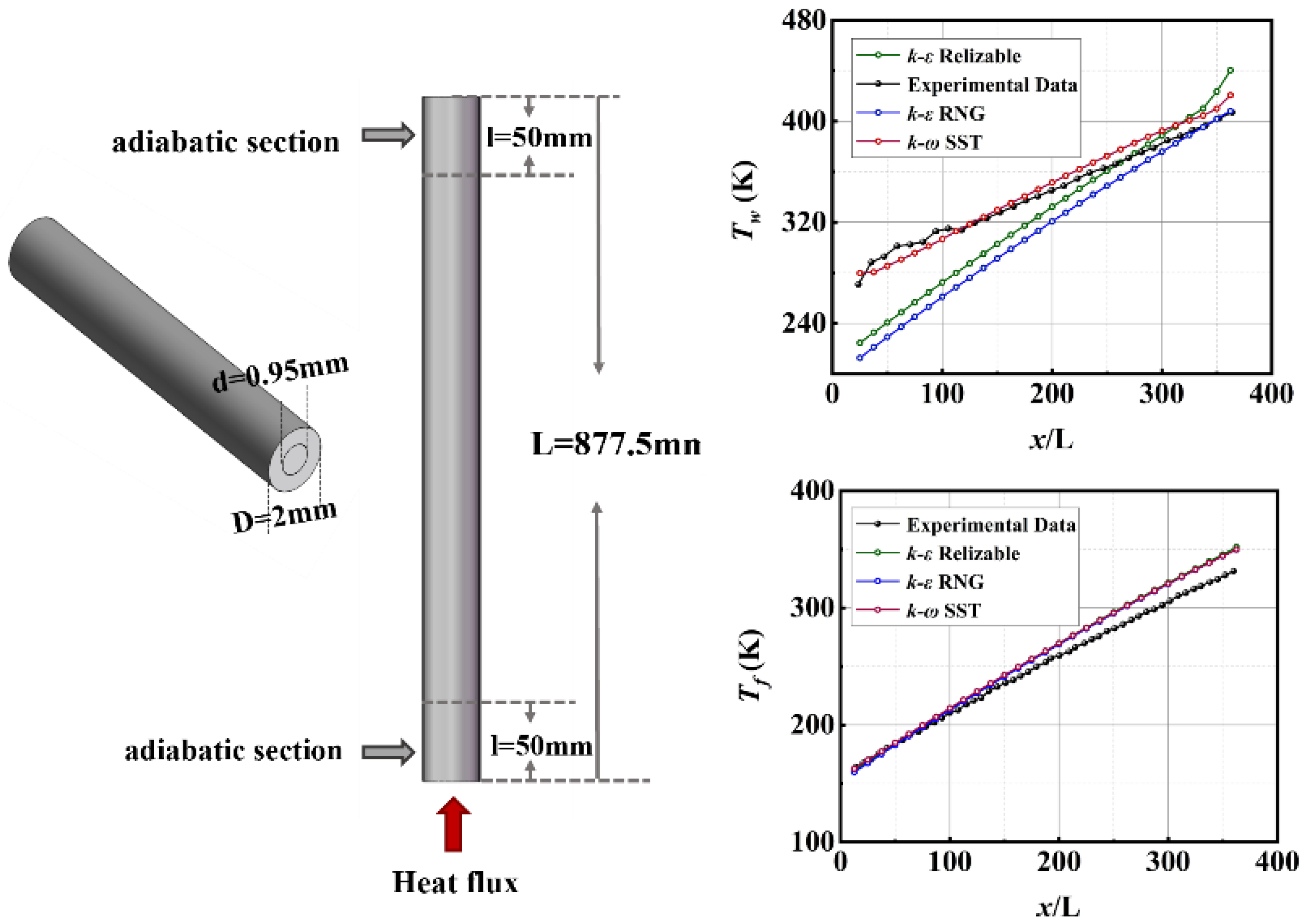
To select the most reliable and accurate turbulence model for simulations, three common turbulence models, k-ω SST, k-ω Relizable, and k-ε RNG, are compared against the experimental results presented by Liu et al. (2015). Figure 6 presents the comparison of wall temperature and fluid temperature variations along the flow direction. It can be intuitively observed that the numerical simulations of the three turbulence models yield consistent fluid temperature rise results, while the k-ω SST turbulence model shows significantly better fitting between its wall temperature increase data and the experimental data than the other two models. Widely validated for supercritical fluid heat transfer in both circular and rectangular channels [10], this model is selected for subsequent numerical simulations, as the strict control of wall y+ < 1 in the present study ensures accurate near-wall turbulence prediction and supports its applicability to the rectangular channel configuration.
Figure 6.
Verification of the turbulence model (model schematic diagram; wall and fluid temperature fitting curves).
The density and quality of meshes have a significant influence on the results of simulation calculations, making mesh independence study a crucial preprocessing step. An insufficient number of meshes tends to compromise the accuracy of simulation calculations, while an excessively large number can impair computational efficiency. To address this trade-off, four mesh design schemes are established and validated using the k-ω SST turbulence model. The mesh counts of Mesh 1 to Mesh 4 are 2,359,488; 3,892,850; 5,347,395; and 8,239,090.
As shown in Table 3, this is a detailed setup of the boundary conditions for the regenerative cooling channel used in the simulation experiments of this paper.
Table 3.
Boundary condition setting.
By comparing the average temperature of the heated wall and the outlet pressure drop across the four schemes, it is observed that the variation in data became negligible once the mesh count reached a certain threshold. As presented in Table 4, when the mesh count exceeded 5 million, further increases in the number of meshes led to only minimal improvements in data accuracy. To balance computational accuracy and time efficiency simultaneously, Mesh 3 is selected for subsequent numerical simulations.
Table 4.
Mesh independence test and scheme selection.
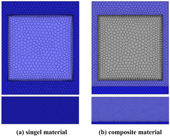
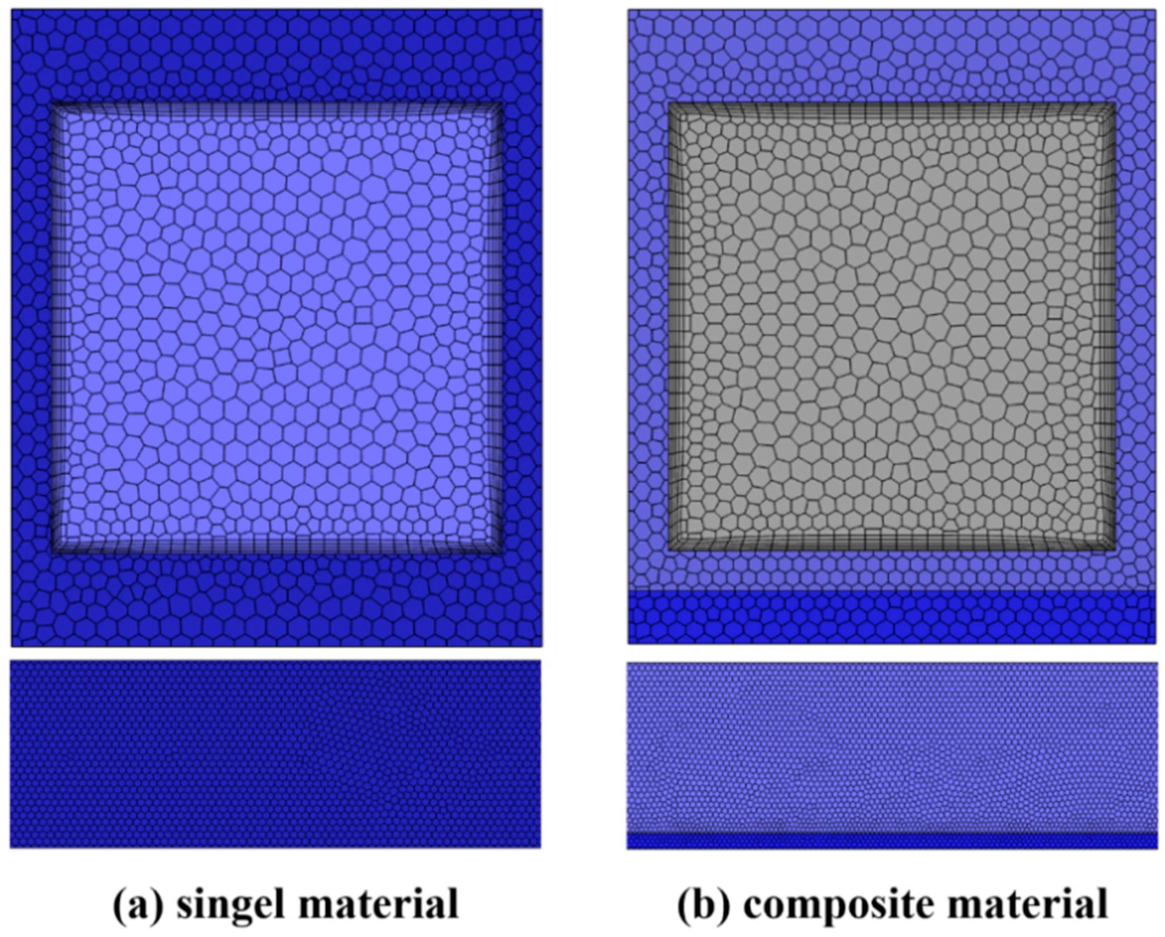
Figure 7 shows the meshing details of rectangular cooling channels for single material and composite material, respectively. After model validation, the k-ω SST turbulence model is selected to solve the turbulence equations. To simulate the fluid flow state accurately, the height of the first layer and the growth rate in the mesh system are, respectively, set at A and B. This keeps the wall y+ value within 1. For the composite material channel in Figure 7b, considering the differences in thermal–physical properties between different materials, this creates thermal resistance at their interface and impedes heat transfer. Therefore, mesh refinement is performed in the interface region of the two materials to more accurately simulate the heat transfer process between solids.
Figure 7.
Schematic diagram of mesh details. (a) Single material; (b) composite material.
As shown in Table 4, this is a detailed explanation of the boundary condition settings for the case study in this paper.
3. Results and Discussion
3.1. Discussion with Material Combinations as Variables
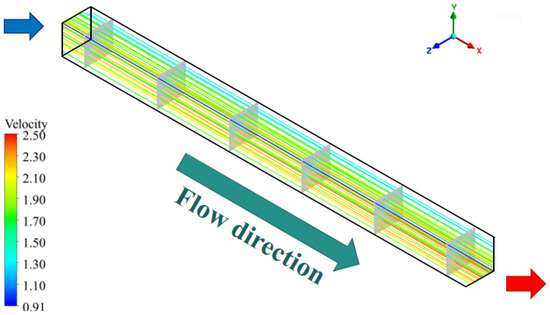
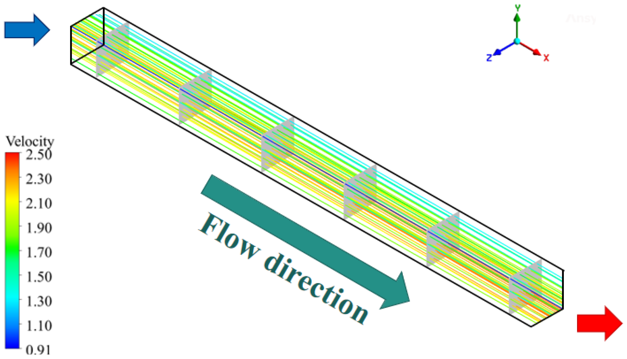
As shown in Figure 8, this is the velocity streamline distribution of the flow field along the flow direction. It can be seen that in the smooth rectangular channel, the fluid in the main flow region flows stably along the x-axis direction. Without the interference of rib structures, there are no obvious vortex structures along the x-axis direction, which is consistent with the basic flow characteristics of supercritical fluids in rectangular channels.
Figure 8.
Velocity streamline distribution diagram for Case 1.
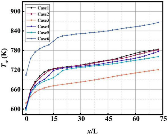
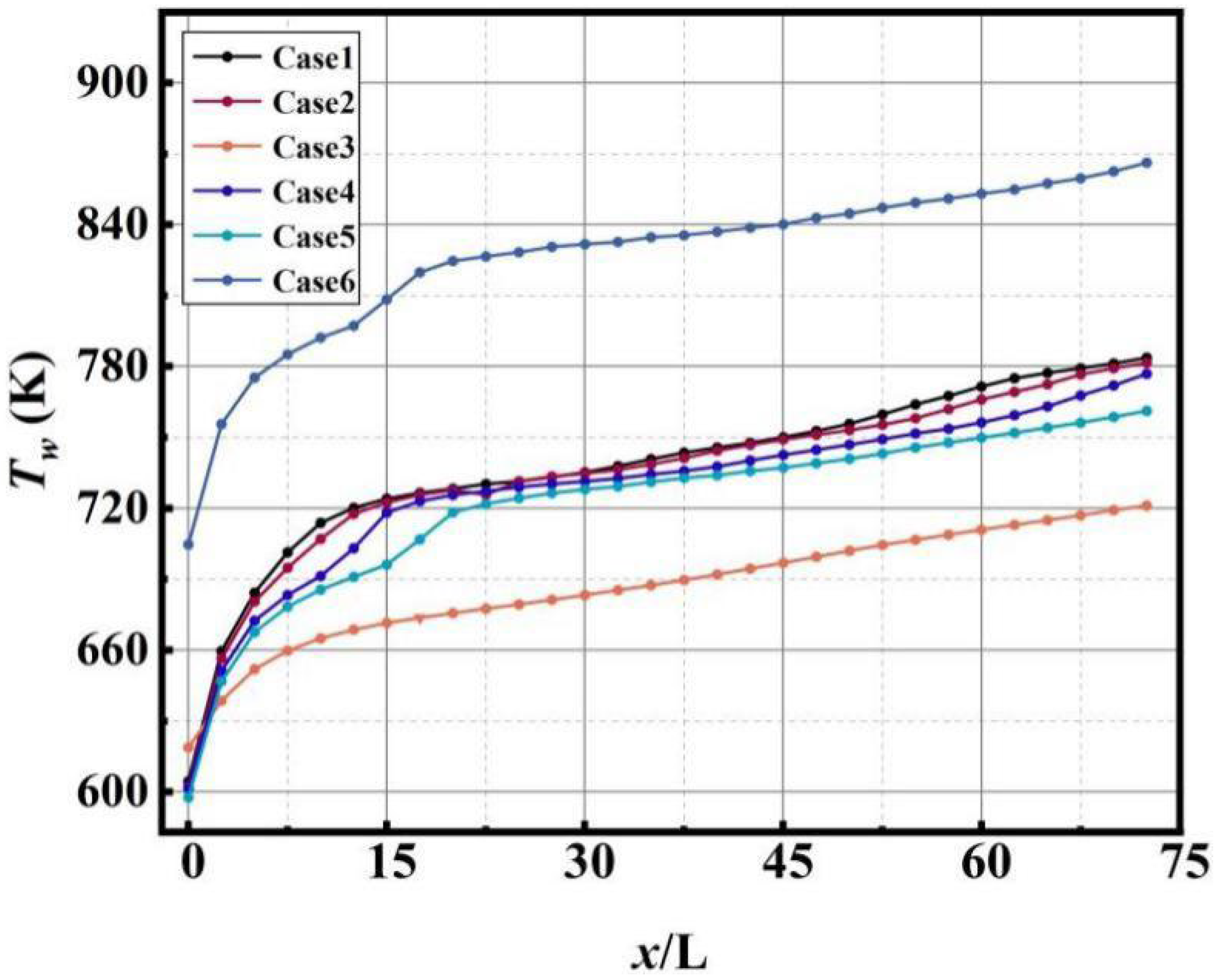
Figure 9 shows the wall temperature distribution along the flow direction for Cases 1–6. There are significant differences in the initial values and growth patterns of wall temperature for different combinations. The temperature rise trends of Cases 5 and 6 are very similar, while Case 6 has a significantly higher initial wall temperature than the other cases. Although both cases are influenced by steel, ZrO2 has an extremely low thermal conductivity, which hinders heat conduction inward from the wall surface, leading to surface heat accumulation during the initial heating stage. For other cases using high thermal conductivity materials, the initial temperatures are consistent. As the flow distance increases, the wall temperature of all cases shows an overall upward trend. In the front section of the channel, where x/L < 20, the temperature rises, and after x/L>20, the rate of temperature increase tends to stabilize, making the differences between cases more pronounced. Case 3 has the lowest overall wall temperature, attributed to the high thermal conductivity of Cu, which can quickly spread heat laterally along the wall, reducing local temperature accumulation. Cases 1 and 2 show similar temperature levels in the middle section of the channel, indicating that the temperature regulation capability of a single material tends to be consistent, while the temperature regulation advantage of composite material systems is more significant.
Figure 9.
Wall temperature distribution along the flow direction for different materials for Cases 1–6.
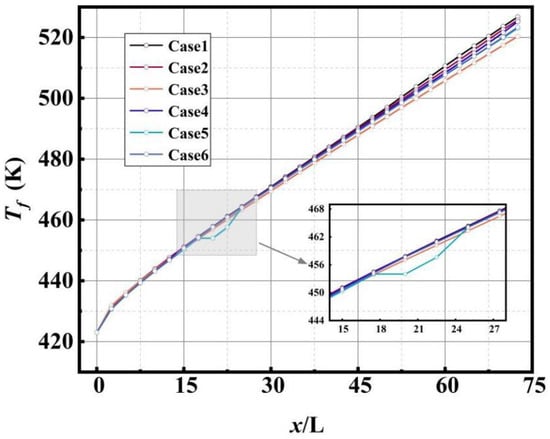
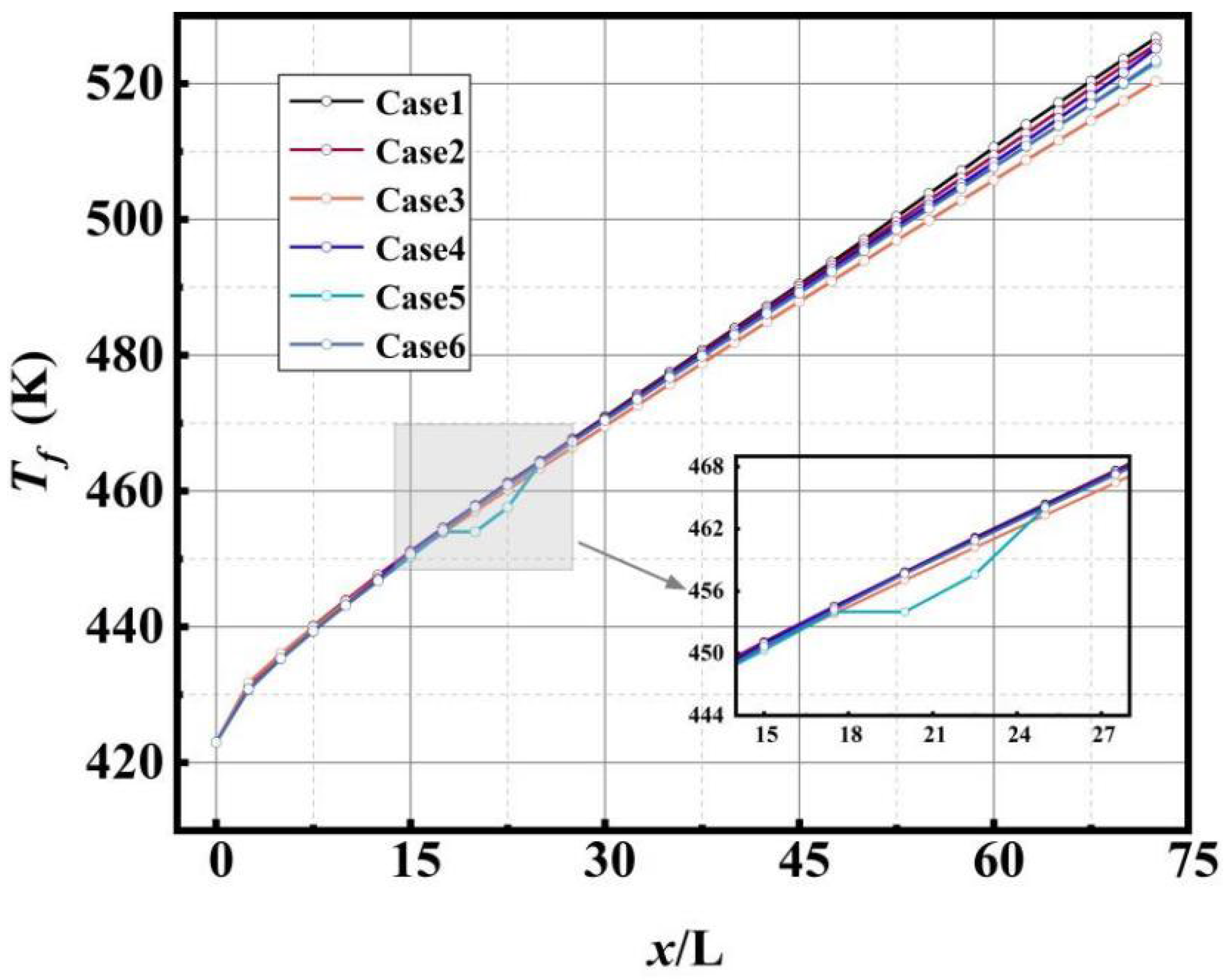
Figure 10 shows the fluid area-weighted temperature distribution along the flow direction for Cases 1–6. The fluid heating rate for Cases 4 and 5 is lower than that for Case 1. Although the thermal conductivity of steel and C/SiC is slightly higher than that of GH3128, the two combined operating conditions have heat transfer resistance. Because C/SiC is an anisotropic material, its heat transfer path perpendicular to the wall is impeded. And here is a thermal resistance effect at the interface of materials with different properties, leading to the heat transfer from the solid domain to the fluid domain needing to overcome the dual barriers of interfacial thermal resistance and composite material directional thermal conductivity limitations. The fluid heating for Case 3 is the most gradual. The reason is that Cu has extremely high thermal conductivity, which can quickly transfer the wall heat to the fluid, allowing the fluid to enter the supercritical state earlier for efficient heat absorption and suppressing the temperature rise amplitude. Case 5 shows a significant temperature inflection point at x/L ≈ 16, which is caused by two factors. First, x/L ≈ 16 corresponds to the transition region from the adiabatic section to the heating section of the channel, where heat increases from nothing and accumulates gradually, causing a stepwise mutation in the fluid temperature change rate. Second, the heat transfer efficiency can only gradually recover after overcoming the interfacial thermal resistance between steel and C/SiC, ultimately forming a temperature inflection point in the transition region. This is consistent with the experimental conclusion of Xin et al. [38].
Figure 10.
Fluid temperature distribution along the flow direction for different materials for Cases 1–6.
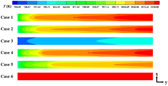
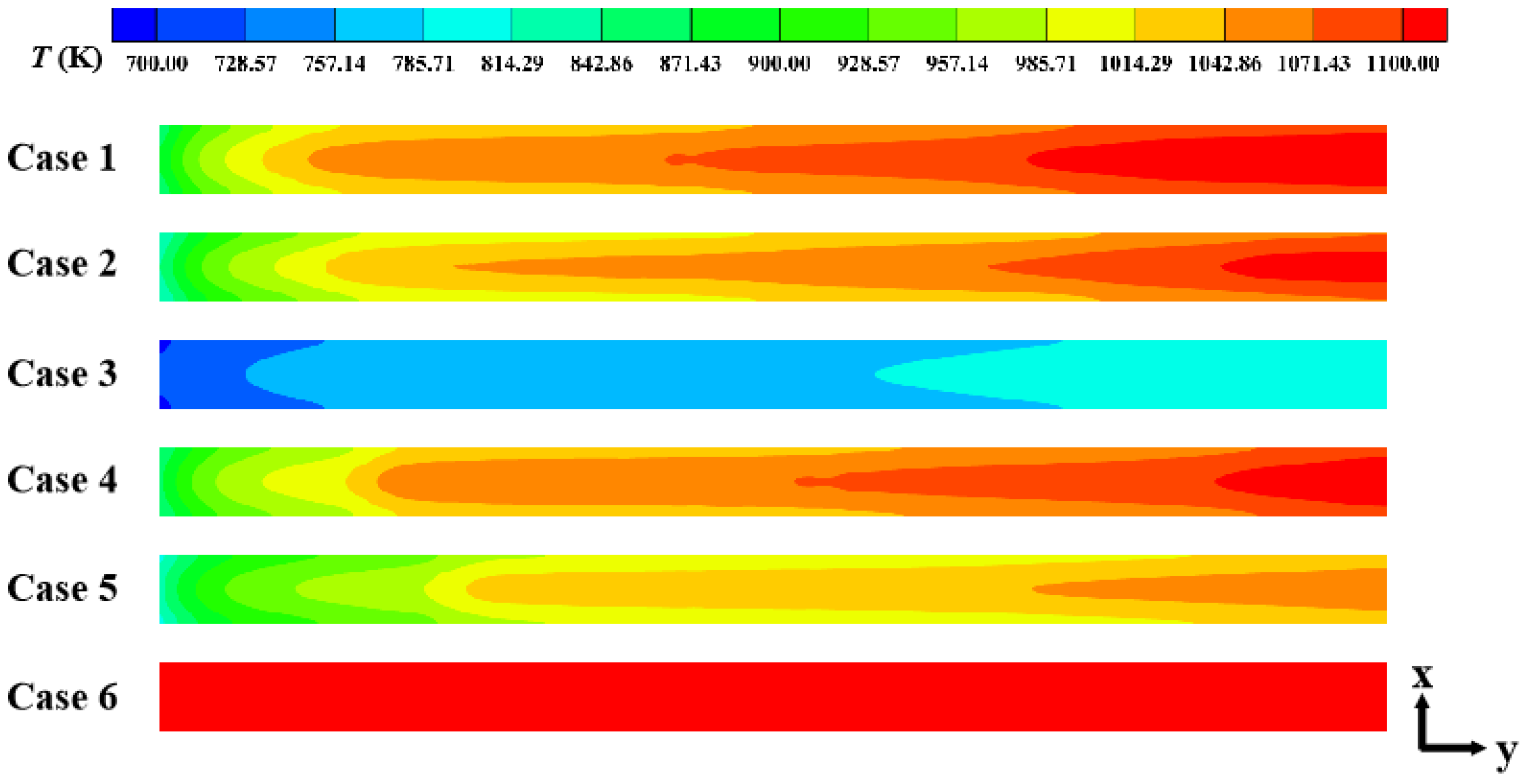
Figure 11 shows the temperature distribution of the heated wall under different material combinations for Cases 1–6. The wall temperature in all cases increases with both heating duration and flow distance. Both single materials, GH3128 and C/SiC, exhibit local high-temperature regions under the same heat flux, while the composite material structure significantly improves the wall temperature distribution characteristics. Case 3, due to the excellent thermal conductivity of Cu, achieves rapid lateral heat diffusion on the wall, reducing the peak temperature by approximately 180 K compared to Case 1; in Cases 4 and 5, the thermal insulation properties of C/SiC result in significant temperature differences at the interface, exhibiting strong thermal resistance effects; Case 6, because of the extremely low thermal conductivity of ZrO2, has an overall wall temperature above 1000 K, making it suitable for scenarios with extremely high temperature requirements for combustion chambers. Although the GH3128 + C/SiC combination combines the advantages of high-temperature resistance and low density, interface thermal resistance leads to local heat accumulation; Cu + GH3128, with the excellent thermal conductivity synergy of the metal matrix, exhibits the best heat transfer efficiency and is suitable for environments requiring efficient heat dissipation. Under the conditions of 3 MPa pressure and 450 K inlet temperature, Case 3 has the lowest wall temperature, making it suitable for low/medium heat flux scenarios with high structural safety requirements. However, the heat transfer performance under high heat flux conditions requires further analysis in conjunction with the heat gradient-driven heat dissipation force.
Figure 11.
Temperature distribution on the heated wall for Cases 1–6 (x-to-y ratio is adjusted to 0.3 in the figure).
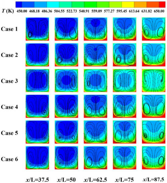
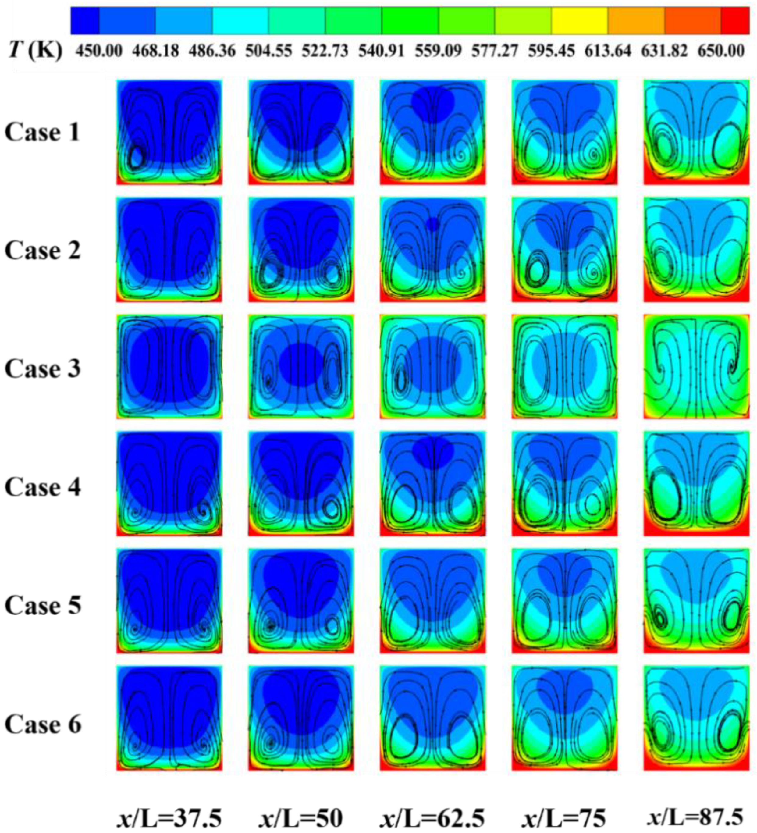
Figure 12 presents the temperature distribution and streamline patterns for Cases 1–6 under identical operating conditions. In Case 3, the wall material exhibits high thermal conductivity, which significantly accelerates lateral heat diffusion. This weakens the localized high-temperature characteristics in the bottom-heated region and forms a more uniform vertical temperature gradient. The temperature distributions in other cases show a high degree of alignment with the spatial position of the heated wall surface, resulting in more pronounced vertical thermal gradients that provide a stronger driving force for heat transfer from the wall to the fluid. This indicates that the thermal properties of materials exert a critical influence on the heat conduction pathways within the channel. The streamline diagrams show that the flow is symmetrically distributed, with two symmetric vortex structures formed in the latter part of the channel, indicating that the flow has fully developed and stabilized; the density of heated fluid in the near-wall region decreases, and buoyancy causes strong local disturbances in the bottom heating area. In Case 3, the streamline vortex is more gradual, and the vortex core is slightly shifted upward, which is related to the weakened buoyancy effect. The rapid lateral heat conduction of Cu reduces the temperature gradient and density difference between the near-wall region and the mainstream region, thereby suppressing buoyancy-driven flow disturbances and making the vortex structure more stable.
Figure 12.
Temperature and streamline distributions on a uniformly distributed cross-section along the y-z direction for Cases 1–6.
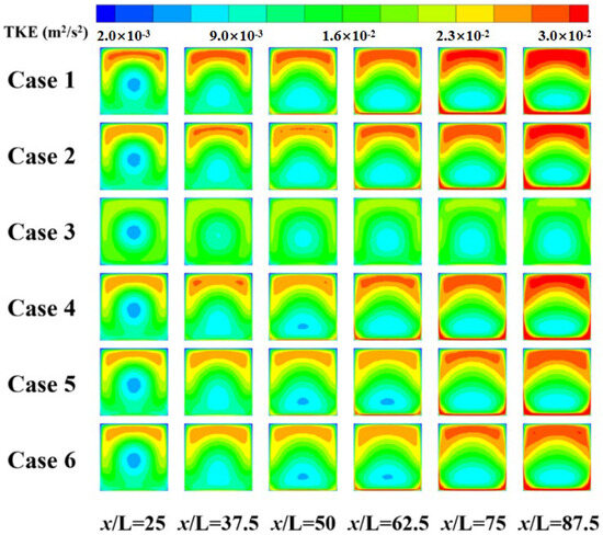
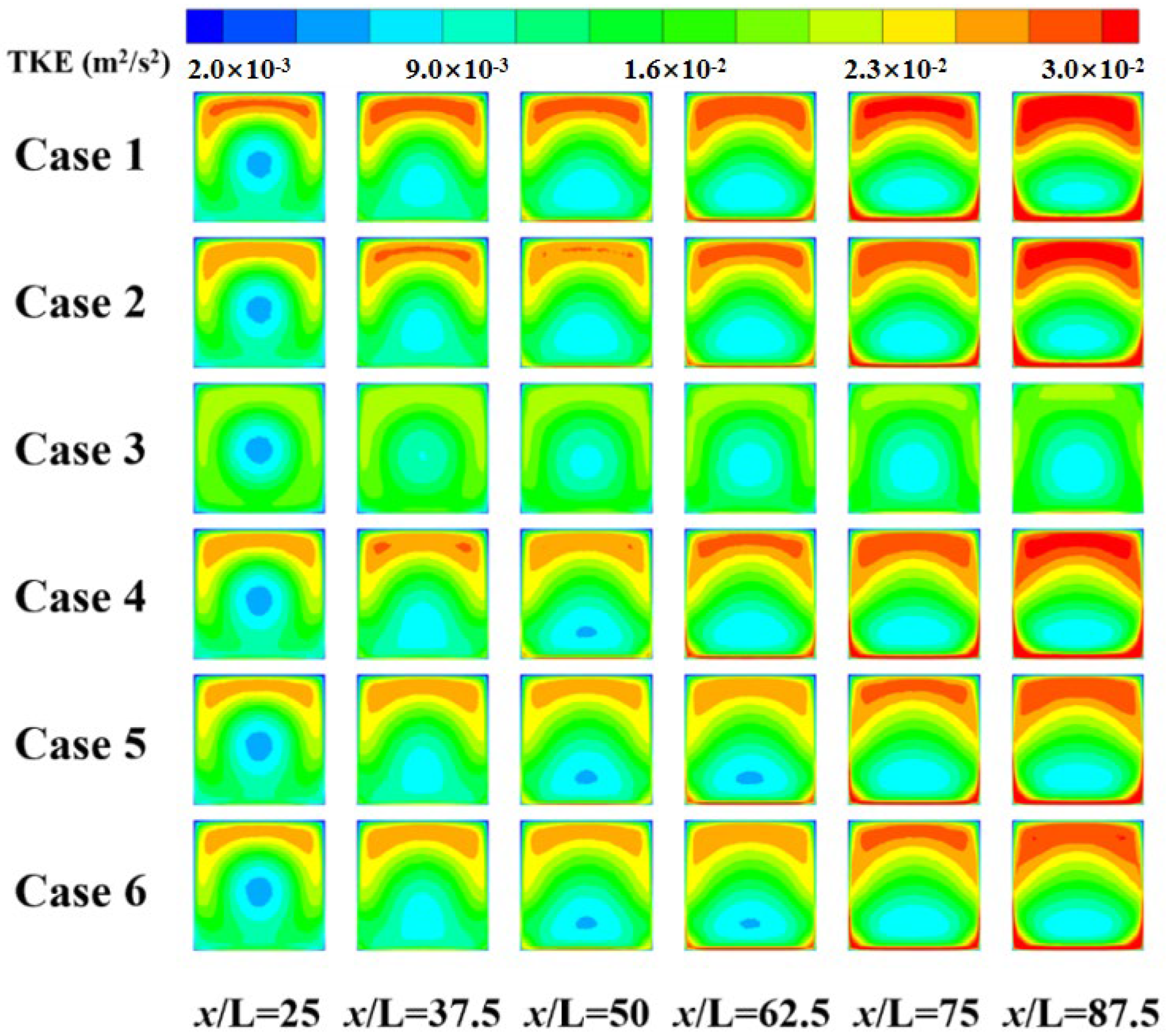
Figure 13 shows the turbulent kinetic energy distribution of fluid in the flow direction for Cases 1–6. The turbulent kinetic energy of the fluid shows an overall increasing trend, with significantly higher turbulent kinetic energy in the outer region of the fluid domain compared to the inner region, which is attributed to the enhancement of turbulence intensity by fluid viscosity. In the front section of the channel, the turbulent kinetic energy exhibits a ring-shaped distribution. As the flow distance increases, this ring-shaped distribution shifts downward, due to the fact that the fluid in the near-wall region, after being heated, enters a supercritical state, resulting in significant changes in its thermophysical properties. This is consistent with the mechanism of the research by Ruan et al. [35]. This creates a distinct density gradient between the near-wall region and the mainstream region, and under the action of gravity, buoyancy effects perpendicular to the flow direction are induced, which in turn affect the turbulent structure. This phenomenon not only alters local heat transfer characteristics but also increases the non-uniformity of wall heat load. Under high-temperature conditions, the coupling effect of gravity-induced secondary flow and thermal buoyancy is more pronounced, which may lead to local overheating or flow separation, consistent with the buoyancy effect patterns of supercritical fluid channels reported by Sun et al. [35]. Within the y-z cross-section, the fluid in the upper part is far from the heating wall, and its turbulent kinetic energy is significantly higher than that in the near-wall region. Moreover, the closer the near-wall region is to the heating wall, the smaller the turbulent kinetic energy, but this phenomenon gradually weakens with increasing flow distance and heat accumulation. This distribution difference originates from the viscous effect of the heating wall hindering turbulence and the free development of turbulence in the far-wall region. As the fluid absorbs heat overall, the temperature gradient decreases, and turbulence mixing intensifies, leading to a gradual reduction in turbulent kinetic energy differences. The turbulent kinetic energy of Case 3 is significantly lower than that of the other conditions. In high-temperature flows, variations in fluid properties, including local density and viscosity, affect the velocity distribution through the momentum equation. Meanwhile, temperature fluctuations directly generate buoyancy fluctuations, which serve as important source terms for driving or suppressing turbulent kinetic energy. However, the high thermal conductivity of Cu effectively smooths out temperature fluctuations in the flow by enhancing molecular heat transport, thereby cutting off the coupling between the temperature field and velocity field through buoyancy or variable property effects. This effect significantly weakens the generation and maintenance mechanisms of turbulent kinetic energy, manifesting as a reduction in overall turbulent intensity.
Figure 13.
Turbulent kinetic energy contours on a uniformly distributed cross-section along the y-z axis for Cases 1–6.
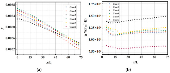
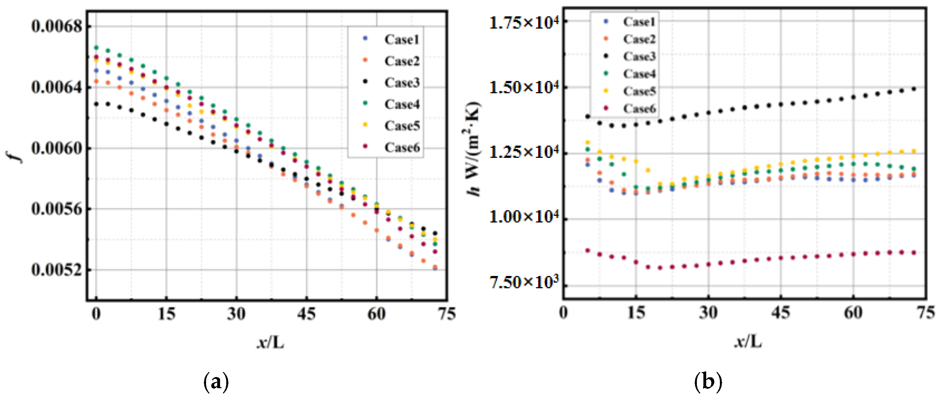
Figure 14 shows the variation trends of the Fanning friction factor (f) and convective heat transfer coefficient (h) along the flow direction for Cases 1–6. It can be seen from Figure 14a that the variation trends of h values under different material combinations are basically the same, showing a trend of first decreasing and then increasing with an overall horizontal tendency. In the initial flow section, the h value remains low due to the low fluid temperature and high viscosity. With the continuous transfer of heat, the fluid gradually enters the supercritical state, and the heat transfer capacity gradually increases and stabilizes. Among all cases, Case 3 has the highest h value, and Case 6 has the lowest, while the h values of other cases are very close. This is consistent with the characteristics that Cu promotes heat transfer due to its high thermal conductivity and ZrO2 hinders heat transfer due to its low thermal conductivity, which further indicates that the thermal conductivity of materials has a significant impact on heat transfer performance. It can be seen from Figure 14b that the influence of different material combinations on f is relatively small. All f values decrease rapidly in the front section of the channel and then gradually stabilize, with a limited decreasing range. The decreased amplitude of f values for Cases 1–6 is within 30%, which shows that the thermal conductivity of materials has little impact on f value. The f value of Case 1 fluctuates in the front section of the channel. With the increase in fluid flow distance, the flow gradually becomes stable, and the variation trend of the f value gradually becomes consistent with that of other material combinations.
Figure 14.
Convective heat transfer coefficient and fanning friction factor for different materials for Cases 1–6. (a) fanning friction factor(f); (b) Convective heat transfer coefficient(h).
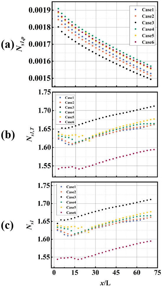
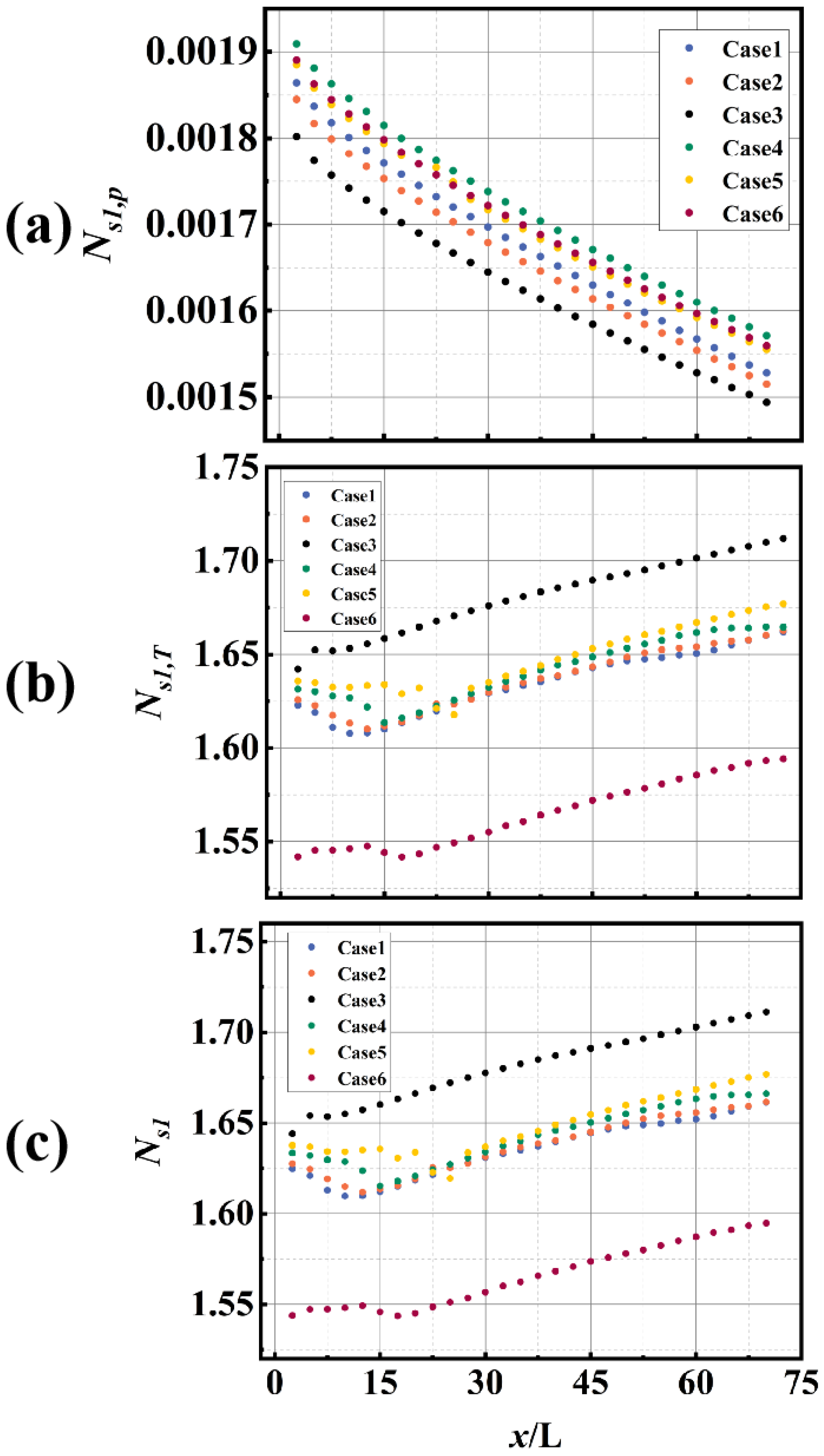
Figure 15 shows the entropy generation of Cases 1–6, in which the heat transfer entropy generation dominates. As presented in Figure 15a, the flow entropy generation exhibits a steady decreasing trend, with the decreasing rate decreasing synchronously. This indicates that the flow in the channel gradually becomes stable, and the entropy increase rate reduces. As shown in Figure 15b, the heat thermal entropy generation changes drastically at the channel inlet and then tends to be gentle. This phenomenon suggests that the temperature difference between the heating wall and the fluid fluctuates sharply in the initial section; with the increase in heat transfer distance, the temperature gradient gradually stabilizes. Among all cases, the thermal entropy generation of Case 3 is the highest, while that of Case 6 is the lowest. This indicates that the thermal conductivity of materials has a significant impact on thermal entropy generation. Materials with good thermal conductivity will increase the irreversible loss of energy; therefore, it is necessary to comprehensively consider the thermal conductivity efficiency and heat loss of materials to achieve efficient heat transfer. The entropy generation of Case 1 fluctuates obviously in the front section of the channel. Considering the convective heat transfer coefficient comprehensively, it shows that the stability of flow also has a significant impact on entropy generation.
Figure 15.
Entropy production under different materials for Cases 1–6. (a) Flow entropy generation; (b) heat transfer entropy generation; (c) total entropy generation.
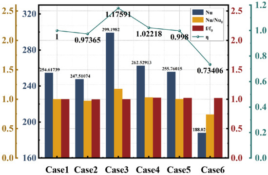
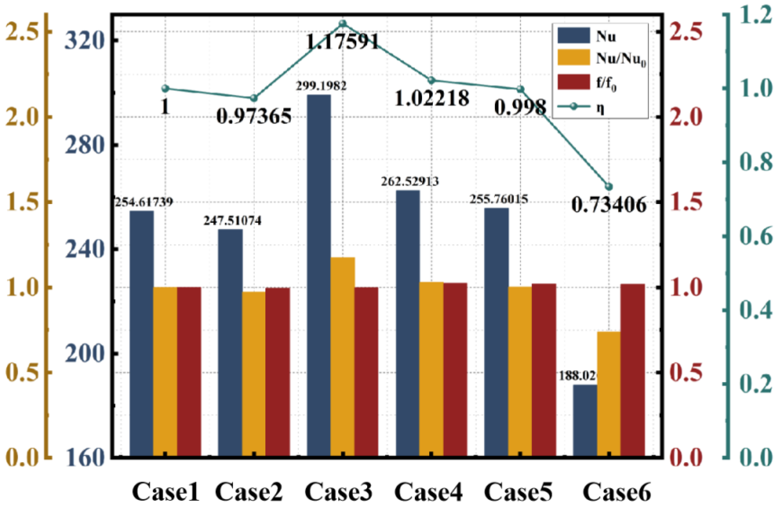
Figure 16 presents the comprehensive comparative data of the Nusselt numbers and overall heat transfer coefficients for Cases 1–6, with Nu0 and f0 of Case 1 (GH3128) as the reference. Under the same operating conditions, significant differences in Nusselt numbers exist among different materials. The Nu value in Condition 3 is the highest, increasing by approximately 17.5% compared to the reference, indicating excellent convective heat transfer capability; in contrast, the Nu value in Condition 6 decreases by about 26.16% relative to the reference, showing relatively weaker convective heat transfer performance. This difference mainly stems from the high thermal conductivity of Cu and the low thermal conductivity of ZrO2, further reflecting the significant impact of material thermal conductivity on regenerative cooling effectiveness. The trend of variation in the overall heat transfer coefficient is basically consistent with that of the Nusselt number. Both Cases 3 and 4 have overall heat transfer coefficients higher than the reference, increasing by 17.6% and 2.2%, respectively, compared to Condition 1, while Condition 6 decreases by 26.6% from the reference. Although there is no significant difference in the thermal conductivities of the material components in these two conditions, differences in other physical parameters also affect the overall heat transfer coefficient, further confirming the advantage of multi-material combination design over single-material design in regenerative cooling channel structures.
Figure 16.
Column charts of Nusselt number, Nusselt number-to-referenced Nusselt number ratio (Case 1), friction coefficient-to-referenced friction coefficient ratio (Case 1), and comprehensive heat transfer coefficient line charts for different materials.
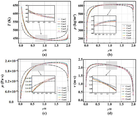
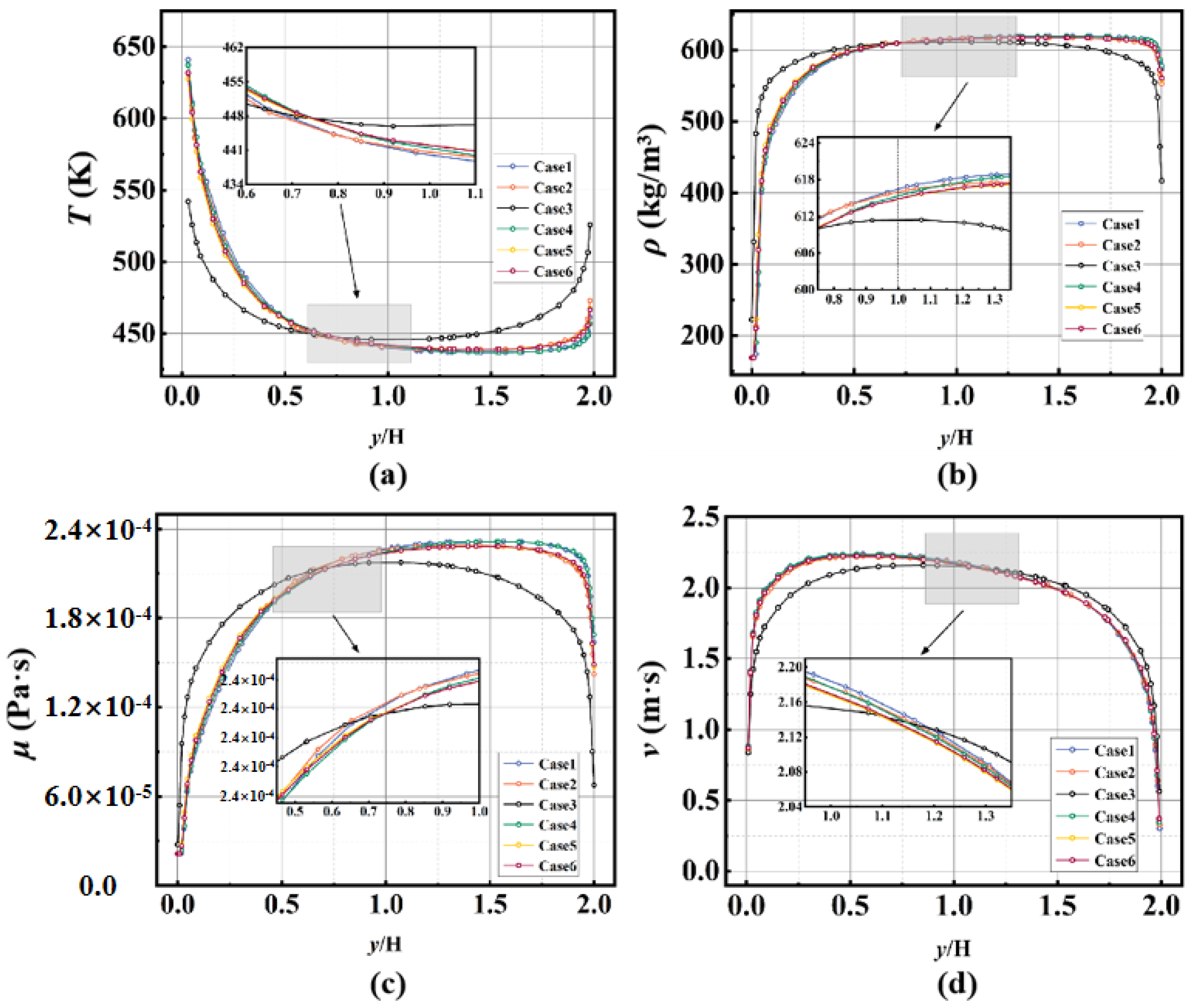
Figure 17 presents the distribution characteristics of temperature, flow velocity, density, and dynamic viscosity of the fluid in the y-z cross-section at the channel inlet where x/L = 50. As shown in Figure 17a, the fluid in the region near the heated wall exhibits a distinct high-temperature characteristic. Affected by the heat transfer rate, the temperature distribution curve is not axisymmetric about the center, with the high-temperature zone shifting slightly downward. Case 3 shows the smallest offset amplitude of the high-temperature zone, and its temperature distribution is closer to axisymmetry, which indicates that this material combination achieves the fastest heat transfer rate and can facilitate heat absorption by more fluid. As illustrated in Figure 17b, combined with the analysis of Figure 4 (thermophysical property diagram of n-decane), the fluid density decreases significantly with the increase in temperature. In the height range of 0.25 <H < 1.75, the slope of the density change tends to be gentle, which implies that the proportion of the fluid entering the supercritical state in this cross-section is limited. It can be seen from Figure 17c that the dynamic viscosity increases first and then decreases with the increase in the distance from the heated wall, and a low-viscosity layer is rapidly formed in the near-wall region. Due to the asymmetry of the temperature distribution, the decreasing trend of viscosity also deviates from central axisymmetry. The fluid in the middle section of the channel is in a high-viscosity state, which is unfavorable for fluid flow; increases frictional resistance; and further affects the fluid flow velocity. As shown in Figure 17d, the velocity distribution is highly negatively correlated with the viscosity distribution, which verifies this regularity. The distributions of temperature, density, dynamic viscosity, and velocity along the height direction of the cross-section in Case 3 all show a high degree of central axisymmetry. This demonstrates that the flow field under this working condition has the optimal stability and the most balanced distribution of thermodynamic performance, with a more uniform heat transfer response on the wall. In addition, the variation in fluid thermophysical properties is the most stable in Case 3, which is closer to the stable stage of the supercritical flow state.
Figure 17.
The distribution of fluid thermophysical properties along the y-axis in the y-z direction at the entrance (x/L = 50). (a) Temperature; (b) density; (c) dynamic; (d) velocity.
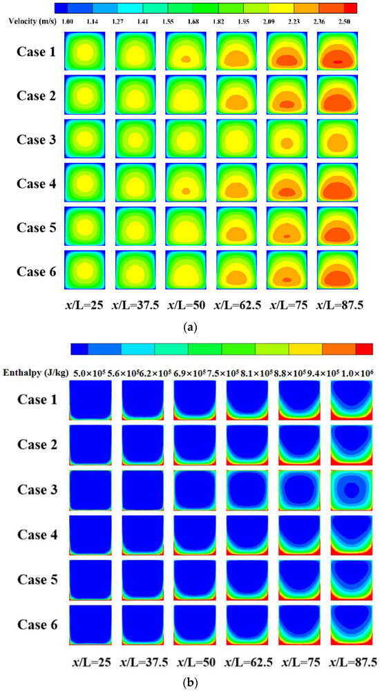
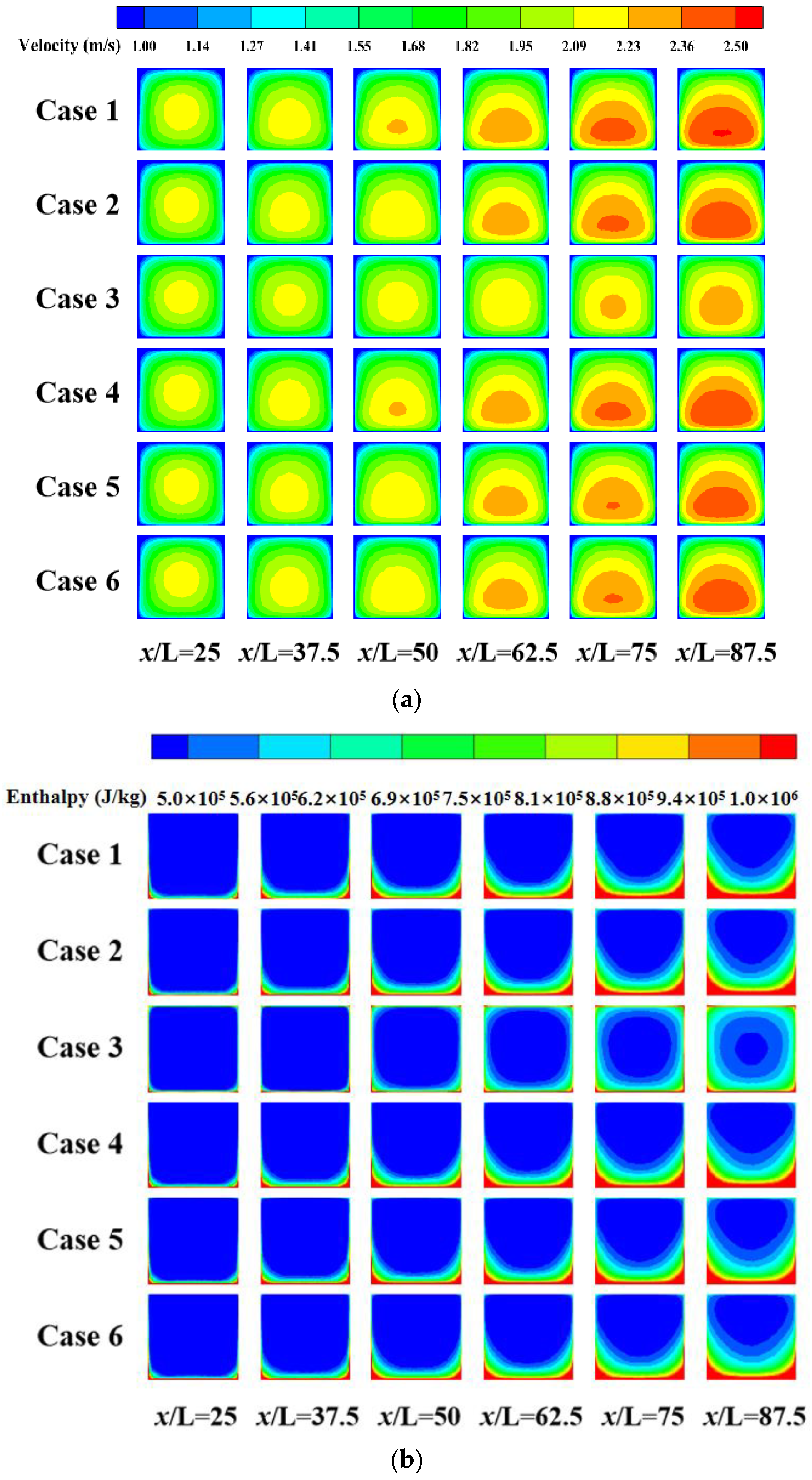
Figure 18 shows the enthalpy and velocity distributions of Cases 1–6 in the y-z cross-section. There are significant differences in the enthalpy and velocity distributions under different material combinations. As shown in Figure 18a, the fluid velocity near the heated wall is higher because the fluid in this region absorbs more heat, leading to a rapid decrease in density. The fluid accelerates due to thermal expansion, forming a distinct convection effect. As the flow distance increases, the high-speed region expands further, but is limited by the heat transfer rate between fluids, the temperature gradient in the vertical direction increases, causing the high-speed region to shift downward. The velocity distribution shift in Case 3 is less noticeable than in the other cases. Combined with the enthalpy image in Figure 18b, the high thermal conductivity of Cu enables rapid lateral heat conduction, preventing uneven fluid heating and mitigating the risk of local overheating. Meanwhile, this characteristic weakens the temperature gradient in the near-wall region, resulting in weaker heat transfer capability under high heat flux compared to other cases.
Figure 18.
Enthalpy and velocity contours on a uniformly distributed cross-section along the y-z axis for Cases 1–6. (a) Velocity; (b) Enthalpy.
3.2. Discussion with Heat Flux as Variables
From the above discussion on material combinations, it is evident that there are significant differences in the flow and heat transfer effects of the channel under different material combinations. To investigate the heat transfer performance of various material combinations in a broader thermal environment, this study further takes heat flux as the variable to conduct a comparative analysis of the heat transfer characteristics of three excellent-performing material combinations (GH3128, Cu + GH3128, steel + C/SiC). The heat flux range is set to 1.5–4.5 MW/m2, with a step size of 1.5 MW/m2.
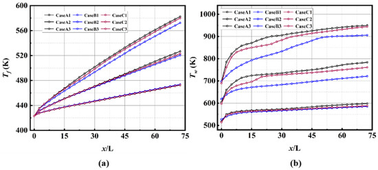
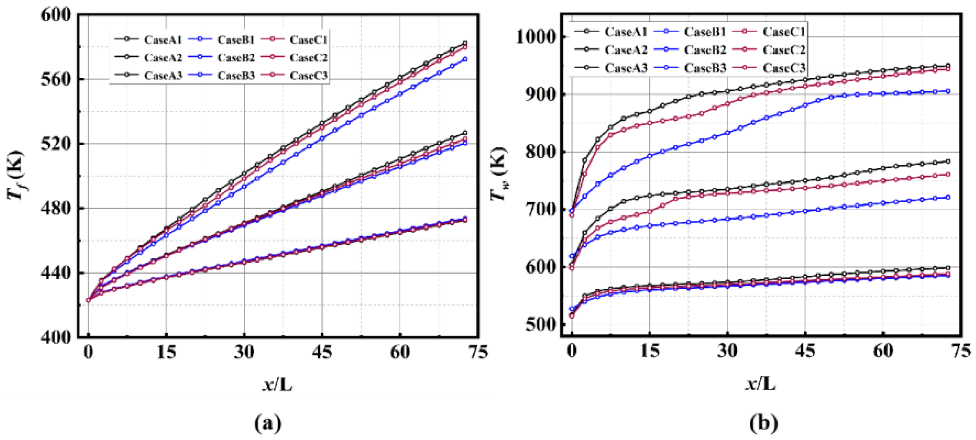
Figure 19 shows the variations in wall temperature and fluid temperature of three material combinations under different heat fluxes. As the heat flux density increases, the overall heating rate of the fluid accelerates. Among the three material combinations, Case B exhibits a lower temperature rise rate compared to Cases A and C, and this difference becomes more pronounced with increasing heat flux. Owing to the high thermal conductivity of Cu, Case B achieves rapid lateral heat diffusion, thereby demonstrating superior temperature regulation capability under high heat flux conditions. In contrast, Cases A and C develop significant temperature gradients in the region near the heated wall as the heat flux increases, which provides a stronger driving force for heat transfer from the wall to the fluid. Combined with the fact that Case 3 has the highest Nusselt number in Figure 16, this further confirms the convective heat transfer capability of this material combination. As the heat flux increases, the wall temperature shows an upward trend. The temperature rise rate of Case B is lower than that of the other two combinations. Moreover, with increasing heat flux, the time required for the wall temperature rise rate to stabilize becomes longer. This indicates that the thermal response capability of materials gradually weakens under extreme high-temperature environments.
Figure 19.
Fluid and wall temperature distribution along the flow direction for different heat fluxes for Cases A1–C3. (a) fluid temperature; (b) wall temperature.
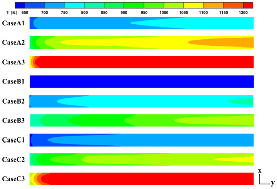
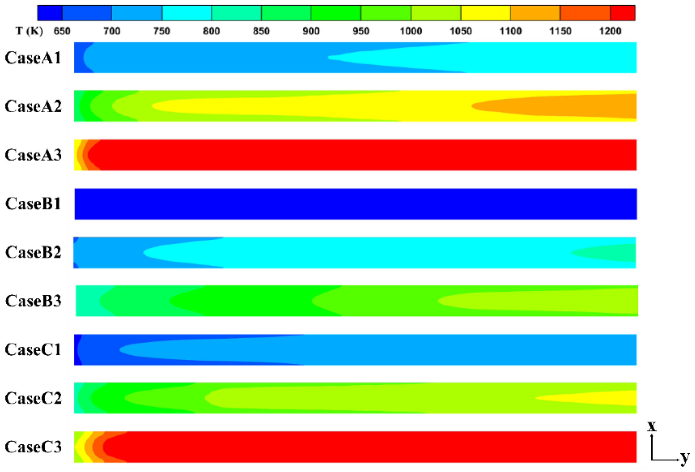
Figure 20 presents the heat wall temperature distribution of three different material combinations under various heat flux conditions. As the heat flux increases, the heating wall temperature exhibits an obvious rising trend, and the temperature discrepancy among different cases gradually widens. Cases A and C show similar variation tendencies, whereas Case B maintains a relatively lower temperature level and a slower temperature rise rate under the same conditions. This is attributed to the high thermal conductivity of the copper-based material, which enables rapid heat diffusion along the wall and effectively alleviates thermal safety risks induced by excessive local temperatures. However, the relatively small temperature gradient in Case B results in weaker heat transfer efficiency than Cases A and C at high thermal loads. At a heat flux of 3 MW/m2, the temperature gradient along the flow direction of the heated wall is more gradual. By contrast, when the heat flux is either decreased or increased, the temperature variation of the heated wall becomes more significant, especially in the upstream region of the channel. Although a rapid temperature rise can enhance heat transfer driving force, the thermal resistance limit and long-term service safety of the structural material must be taken into account. Accordingly, it is essential to determine the applicable thermal operating range for the proposed design in practical engineering applications.
Figure 20.
Temperature distribution on the heated walls for Cases A1–C3 (x-to-y ratio is adjusted to 0.3 in the figure).
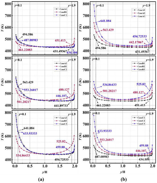
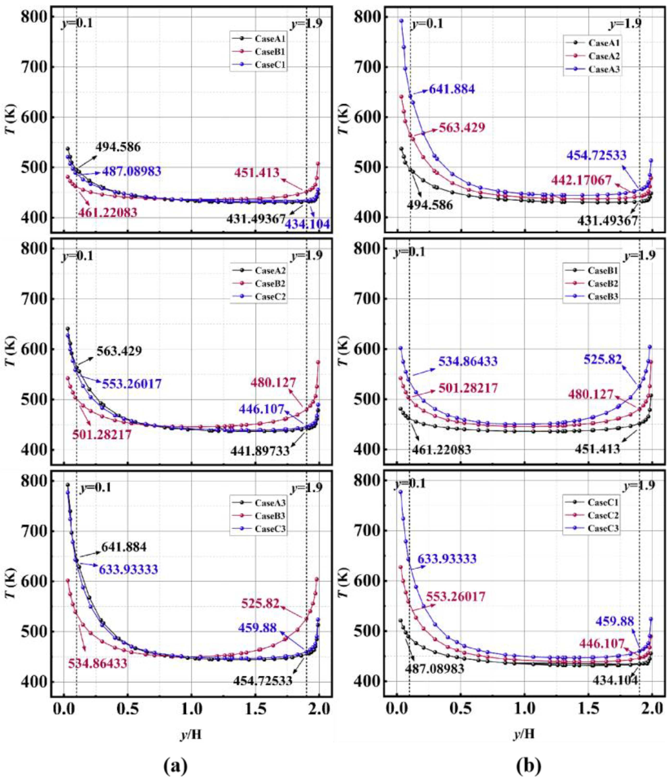
Figure 21 illustrates the temperature distribution along the y-axis in the y-z cross-section at the channel center. An analysis of the average temperature for three material combinations under different heat fluxes is conducted, focusing on temperatures along parallel lines near the heated wall (y = 0.1 mm) and away from the heated wall (y = 1.9 mm). As shown in Figure 21a, for the same material combination under varying heat fluxes, the temperature gradient increases significantly with increasing heat flux, particularly resulting in a marked expansion of the temperature difference between the region near the heated wall and the region away from it. At y = 0.1 mm, the temperature difference between Cases A and C remains within 10 K; however, the temperature difference between Case A and B rises sharply from 33.37 K to 107.02 K, indicating insufficient heat transfer in the fluid and a reduction in heat transfer efficiency. The temperature distribution of Case B still exhibits symmetry about the central axis height, suggesting that Case B can maintain a uniform temperature field even under high heat flux conditions. This effectively mitigates local overheating and further enhances the utilization efficiency of the fluid during the heat transfer process. As shown in Figure 21b, different material combinations have a significant impact on the temperature distribution under the same heat flux. Under high heat conditions, Case B exhibits a more gradual temperature gradient and a more uniform temperature distribution in the channel center region, with better symmetry than Cases A and C. When q increases from 1.5 MW/m2 to 4.5 MW/m2, the temperature differences between Cases A and C at y = 0.1 mm are 147.30 K and 146.84 K, respectively, whereas the temperature difference for Case B is 73.64 K, which is significantly lower than those of Cases A and C. This indicates that the superior thermal conductivity of Case B can reduce the risk of local heat accumulation. While the high temperature gradients in Cases A and C impose local thermal load pressure, they can effectively drive heat transfer.
Figure 21.
The distribution of temperature along the y-direction of different heat fluxes for Cases A1-C3. (a) Different material combinations under the same temperature conditions. (b) The same material combination under different temperature conditions.
4. Conclusions
This study selects five materials (GH3128, C/SiC, Cu, steel, ZrO2) as wall materials for regenerative cooling channels, conducting a comprehensive analysis of their overall flow and heat transfer characteristics. The research covers three engineering materials with broad application prospects: metals, ceramics, and C/SiC composite materials. Based on the feasibility of physical combinations between different materials, GH3128 is chosen as the benchmark case, and five composite structure schemes (C/SiC, Cu + GH3128, GH3128 + C/SiC, steel + C/SiC, and steel + ZrO2) are constructed for comparative analysis. By altering material combinations and heat flux, the heat transfer characteristics of a single rectangular channel are comprehensively simulated and analyzed. The analysis includes multiple data points, such as wall and fluid temperatures, flow velocity, turbulent kinetic energy, fluid friction coefficients, and comprehensive heat transfer characteristics. The following conclusions are drawn:
1. Influence characteristics of material thermophysical properties. When the composite structure schemes showed significant characteristics under the same working conditions, physical quantities of obvious differences from the base case were observed. These include wall temperature, fluid turbulent kinetic energy, and comprehensive heat transfer characteristics. Taking the Nusselt number and comprehensive heat transfer coefficient as examples, Case 3 (Cu + GH3128) demonstrates the highest Nusselt number, approximately 17.5% higher than the baseline value. In contrast, Case 6 (steel + ZrO2) shows a Nusselt number about 26.16% lower than the baseline. The comprehensive heat transfer coefficient for Case 3 is 17.6% higher than the baseline, while Case 6 is 26.6% lower. This further indicates that even when materials are coupled with each other, their dominant role is still determined by key parameters such as thermal conductivity, specific heat capacity, and density of each component material. Moreover, materials with better thermophysical properties contribute more significantly to the overall heat transfer effect in the composite structure.
2. Influence of the coupling effect between materials on heat transfer performance. Among the four multi-material combination schemes adopted in this paper, the overall and local heat transfer characteristics of the channel show obvious dual characteristics of synergy and inhibition. During the simulation, it is noticed that the fluid heat absorption rate slowed down in the early stage. Through the analysis of fluid density and wall temperature at the same position, it is found that due to differences in physical properties, a thermal resistance effect will occur at the material interface. This leads to a decrease in local heat transfer efficiency, which in turn affects the cooling efficiency. It is necessary to fully consider the thermal matching of material coupling in experiments to avoid the risk of deformation and cracking at the coupling interface.
3. Response characteristics of material thermophysical properties under different thermal pressures. Building upon the basic analysis, three typical material combination schemes are selected to investigate their heat transfer performance variation patterns under high-temperature conditions. This study revealed that an increase in heat flux density significantly alters the heat transfer characteristics of different material combinations. While the property variation patterns of the same scheme are basically consistent, there exist differences in variation rates. When the heat flux density increases threefold (from 1.5 to 4.5 MW/m2), the temperature difference of the Cu + GH3128 combination (Case B) is 73.64 K, which is only half of that of the GH3128 (Case A) and steel + C/SiC (Case C). However, under the same heat flux, the temperature difference between Cases A and C remains below 10 K, whereas Case B increases to 107.02 K. This indicates that temperature uniformity and strong thermal gradient have different applicability scenarios: the former is conducive to reducing local heat accumulation and enhancing structural stability, while the latter can provide a stronger heat transfer driving force. In practical applications, it is necessary to select the appropriate material combination according to specific requirements to achieve optimal flow and heat transfer effects.
4. Balance between heat transfer efficiency and structural safety. In particular, a significant temperature gradient is formed in the material interface transition zone, which may affect the long-term service safety of the structure. Compared with the rapid increase in wall thermal pressure caused by the increase in heat flux, the rate of increase of fluid temperature is significantly slower. Therefore, in the innovation process, it is still necessary to use materials with high strength and a high melting point as the base material, supplemented by reinforcing phases with high thermal conductivity and a low thermal expansion coefficient. This approach can further improve heat transfer efficiency on the premise of ensuring structural safety under extreme thermal environments.
Author Contributions
Methodology, J.L.; Software, G.Z.; Investigation, G.Z. and Y.J.; Original Draft Preparation, G.Z.; Review and Editing, G.Z., Y.J. and J.L. All authors have read and agreed to the published version of the manuscript.
Funding
This research received no external funding. The APC was funded by Professor Liu.
Data Availability Statement
The raw data supporting the conclusions of this article will be made available by the authors on request.
Conflicts of Interest
The authors declare no conflicts of interest.
Nomenclature
| Latin | ||
| A | Heated area | mm2 |
| D | Diameter | mm |
| Dh | Hydraulic diameter of the channel | mm |
| f | Fanning friction factor | |
| g | Gravity | m/s2 |
| H | Height of the fluid domain | mm |
| hch | The thickness of the wall | mm |
| h | Convective heat transfer coefficient | W/m2·K |
| k | Turbulent kinetic energy | m2/s2 |
| Ns,1 | The entropy generation number of Hesselgreaves | |
| Nu | Nusselt number | |
| P | Pressure | MPa |
| q | Heat flux | MW/m2 |
| qm | Mass flow rate of the inlet | kg/s |
| Re | Reynolds number | |
| Volume entropy generation rate due to fluid friction | W/m3·K | |
| Volume entropy generation rate due to heat transfer | W/m3·K | |
| T | Temperature | K |
| u | Mainstream velocity | m/s |
| v | Velocity | m/s |
| x,y,z | Streamwise, spanwise, and normal directions | |
| Greek | ||
| η | Combined heat transfer performance factor | |
| ρ | Density | kg/m3 |
| λ | Thermal conductivity | W/m·K |
| μ | Dynamic viscosity | Pa·s |
| ω | Specific dissipation rate | s−1 |
| Subscripts | ||
| f | Fluid | |
| in | Inlet | |
| out | Outlet | |
| w | Wall |
References
- Liu, C.Y.; Ai, J.D.; Zhang, J.C.; Li, X.; Zhao, Z.J.; Huang, W. Research progress of the flow and combustion organization for the high-Mach-number scramjet: From Mach 8 to 12. Prog. Aerosp. Sci. 2025, 155, 101094. [Google Scholar] [CrossRef] [Scilit]
- Cheng, K.L.; Xu, J.; Dang, C.L.; Qin, J.; Jing, W.X. Performance evaluation of fuel indirect cooling based thermal management system using liquid metal for hydrocarbon-fueled scramjet. Energy 2022, 260, 125068. [Google Scholar] [CrossRef] [Scilit]
- Zhang, S.L.; Li, X.; Zuo, J.Y.; Qin, J.; Cheng, K.L.; Feng, Y.; Bao, W. Research progress on active thermal protection for hypersonic vehicles. Prog. Aerosp. Sci. 2020, 119, 100646. [Google Scholar] [CrossRef] [Scilit]
- Liu, J.; Xu, M.Y.; Ma, K.; Liu, C.Y.; Xi, W.X. Heat transfer and flow structures of supercritical n-decane in a regenerative cooling channel loaded with non-uniform heat flux. Front. Energy Res. 2022, 10, 985220. [Google Scholar] [CrossRef] [Scilit]
- Landsberg, W.O.; Wheatley, V.; Smart, M.K.; Veeraragavan, A. Performance of high mach number scramjets—Tunnel vs. flight. Acta Astronaut. 2018, 146, 103–110. [Google Scholar] [CrossRef] [Scilit]
- Zuo, J.Y.; Zhang, S.L.; Qin, J.; Bao, W.; Cui, N.G. Performance evaluation of regenerative cooling/film cooling for hydrocarbon fueled scramjet engine. Acta Astronaut. 2018, 148, 57–68. [Google Scholar] [CrossRef] [Scilit]
- Zhu, Y.H.; Peng, W.; Xu, R.N.; Jiang, P.X. Review on active thermal protection and its heat transfer for airbreathing hypersonic vehicles. Chin. J. Aeronaut. 2018, 31, 1929–1953. [Google Scholar] [CrossRef] [Scilit]
- Luo, S.B.; Xu, D.Q.; Song, J.W.; Liu, J. A review of regenerative cooling technologies for scramjets. Appl. Therm. Eng. 2021, 190, 116754. [Google Scholar] [CrossRef] [Scilit]
- Wu, K.; Feng, Y.; Li, D.S.; Xu, S.; Qin, J.; Huang, H.Y. Experimental investigations on transient flow and heat transfer characteristics of RP-3 at supercritical pressure. Appl. Therm. Eng. 2022, 213, 118678. [Google Scholar] [CrossRef] [Scilit]
- Sun, X.; Meng, H.; Zheng, Y. Asymmetric heating and buoyancy effects on heat transfer of hydrocarbon fuel in a horizontal square channel at supercritical pressures. Aerosp. Sci. Technol. 2019, 93, 105358. [Google Scholar] [CrossRef] [Scilit]
- Gong, K.Y.; Zhang, Y.; Wang, X. Buoyancy effect on heat transfer and surface coking of hydrocarbon fuel in horizontal square channel at supercritical pressures. J. Anal. Appl. Pyrolysis 2022, 168, 105738. [Google Scholar] [CrossRef] [Scilit]
- Wu, K.; Feng, Y.; Cao, Y.; Huang, H.Y.; Qin, J. Thermal response modeling and analysis of hydrocarbon fuel transient flow and heat transfer at supercritical pressure. Int. J. Therm. Sci. 2023, 192, 108374. [Google Scholar] [CrossRef] [Scilit]
- Liang, Z.R.; Chen, Y.J.; Liu, H.Y.; Wang, C.M.; Chen, L.F. Characterizing combustion performance and PM emissions of an aviation compression ignition engine by fueling RP-3 kerosene and RP-3/pentanol blends. Int. J. Engine Res. 2023, 24, 1312–1326. [Google Scholar] [CrossRef] [Scilit]
- Liu, S.Y.; Feng, Y.; Cao, Y.; Gong, K.Y.; Zhou, W.X.; Bao, W. Numerical simulation of supercritical catalytic steam reforming of aviation kerosene coupling with coking and heat transfer in mini-channel. Int. J. Therm. Sci. 2019, 137, 199–214. [Google Scholar] [CrossRef] [Scilit]
- Liu, Y.L.; Chen, J.X.; Xu, G.Q.; Gascoin, N.; Fu, Y.C. Experimental investigation of convective heat transfer to supercritical pressure n-decane and RP-3 under trans-critical and cracking states. Case Stud. Therm. Eng. 2025, 69, 106050. [Google Scholar] [CrossRef] [Scilit]
- Li, Y.H.; Han, H.Z.; Xu, Z.X.; Luo, W. Mechanism of the Effect of Al Nanoparticles on n-Decane Cracking: An Experimental and ReaxFF Simulation Study. Ind. Eng. Chem. Res. 2025, 64, 11851–11867. [Google Scholar] [CrossRef] [Scilit]
- Wang, B.; Yan, W.R.; Gong, X.L.; Zhu, Q. New strategy for coking pathway regulation during n-decane cracking with the additives containing hydroxyl groups. Fuel 2024, 356, 129620. [Google Scholar] [CrossRef] [Scilit]
- Huang, Q.; Chen, Y.; Bao, Z.W.; Zhu, Q. Effects of Dissolved Oxygen Concentration on Supercritical Thermal Oxidation Coking of RP-3 Aviation Kerosene. Pet. Chem. 2021, 61, 1296–1304. [Google Scholar] [CrossRef] [Scilit]
- Jiang, Y.G.; Xu, Y.X.; Qin, J.; Zhang, S.L.; Chetehouna, K.; Gascoin, N.; Bao, W. The flow rate distribution of hydrocarbon fuel in parallel channels with different cross section shapes. Appl. Therm. Eng. 2018, 137, 173–183. [Google Scholar] [CrossRef] [Scilit]
- Zhang, X.R.; Guo, W.J.; Gao, G.J.; Xi, W.X.; Liu, J.; Sunden, B. Numerical investigations of flow and heat transfer characteristics of a regenerative cooling channel using supercritical CO2 with different cross-section shapes. Int. J. Therm. Sci. 2025, 215, 109965. [Google Scholar] [CrossRef] [Scilit]
- Li, Y.H.; Yang, K.; Wang, Z.W.; Pan, Y.; Wang, N.; Zhan, T.T. Convective heat transfer of hydrocarbon fuels in regenerative cooling channels with topologically optimized cross-sectional shapes. Appl. Therm. Eng. 2025, 269, 126151. [Google Scholar] [CrossRef] [Scilit]
- Liu, J.; Guo, W.J.; Yin, M.X.; Xi, W.X.; Sunden, B. Flow and heat transfer characteristic of regenerative cooling channels using supercritical CO2 with circular tetrahedral lattice structures. Case Stud. Therm. Eng. 2025, 71, 106204. [Google Scholar] [CrossRef] [Scilit]
- Yi, Z.C.; Wang, T.Y.; Yao, Y.F.; Li, P.B.; Sun, M.B.; Chen, J.K.; An, B.; Liang, C.H.; Wang, J.R.; Li, M.L.; et al. Parametric study of flow and heat transfer characteristics in a regenerative cooling channel with crescent-shaped ribs under non-uniform heat flux. Results Eng. 2025, 28, 107033. [Google Scholar] [CrossRef] [Scilit]
- Zhang, J.X.; Han, H.Z.; Zhu, Q. Multi-objective optimization of the cooling performance of a mini-channel with boot-shaped ribs in transcritical regions using RSM and MOGA. Numer. Heat Transf. Part A-Appl. 2020, 78, 737–755. [Google Scholar] [CrossRef] [Scilit]
- Yu, R.T.; Zou, X.Y.; Han, H.Z.; Zhu, Q.; Gao, R.C. Analysis of the effect of pyrolytic coking on the flow and heat transfer performance of n -decane in cooling channels at supercritical pressure. Int. J. Heat Mass Transf. 2022, 195, 123147. [Google Scholar] [CrossRef] [Scilit]
- Tian, K.; Yang, P.; Tang, Z.C.; Wang, J.; Zeng, M.; Wang, Q.W. Effect of pyrolytic reaction of supercritical aviation kerosene RP-3 on heat and mass transfer in the near-wall region. Appl. Therm. Eng. 2021, 197, 117401. [Google Scholar] [CrossRef] [Scilit]
- Ruan, B.; Huang, S.Z.; Meng, H.; Gao, X.W. Flow dynamics in transient heat transfer of n-decane at supercritical pressure. Int. J. Heat Mass Transf. 2017, 115, 206–215. [Google Scholar] [CrossRef] [Scilit]
- Huang, S.Z.; Ruan, B.; Meng, H.; Gao, X.W. Boundary effects on flow oscillations in transient heat transfer of n-decane at supercritical pressure. Int. J. Heat Mass Transf. 2018, 123, 821–825. [Google Scholar] [CrossRef] [Scilit]
- Yin, L.; E, J.Q.; Ding, J. Effect of Cooling Header on the Hydrocarbon Fuel Flow Distribution in a Regenerative Cooling Channel. Int. J. Aerosp. Eng. 2022, 2022, 1–10. [Google Scholar] [CrossRef] [Scilit]
- Jiang, Y.G.; Qin, J.; Xu, Y.X.; Zhang, S.L.; Chetehouna, K.; Gascoin, N.; Bao, W. The influences of the header geometry on hydrocarbon fuel flow distribution in compact parallel channels. Aerosp. Sci. Technol. 2018, 79, 318–327. [Google Scholar] [CrossRef] [Scilit]
- Elmouazen, H.; Zhang, X.B.; Gibreel, M.; Ali, M. Heat transfer enhancement of hydrogen rocket engine chamber wall by using V-shape rib. Int. J. Hydrogen Energy 2022, 47, 9775–9790. [Google Scholar] [CrossRef] [Scilit]
- Elmouazen, H.; Zhang, X.B.; Gibreel, M. Enhanced heat transfer and flow topology of hydrogen regenerative-cooling channels with novel X-shape ribs. Int. J. Hydrogen Energy 2023, 48, 32110–32124. [Google Scholar] [CrossRef] [Scilit]
- Jing, T.T.; Xin, Y.P.; Zhang, L.; Sun, X.; He, C.W.; Wang, J.C.; Qin, F. Application of Carbon Fiber-Reinforced Ceramic Composites in Active Thermal Protection of Advanced Propulsion Systems: A Review. Chem. Rec. 2023, 23, e202300022. [Google Scholar] [CrossRef] [Scilit]
- Xin, Y.P.; Zhao, Z.; Jing, T.T.; Liu, S.Y.; Qin, F.; Sun, X.; Zhang, L. Flow and heat transfer characteristics of hydrocarbon fuel in lightweight C/SiC regenerative cooling combustor. Aerosp. Sci. Technol. 2024, 151, 109280. [Google Scholar] [CrossRef] [Scilit]
- Liu, J.; Guo, W.; Zhao, G.; Ma, J.; Xi, W.; Sunden, B. Study on Heat Transfer Characteristics of Supercritical CO2/n-decane Composite Double Triangular Regenerative Cooling for Scramjets. Aerosp. Sci. Technol. 2026, 172, 111725. [Google Scholar] [CrossRef] [Scilit]
- Quan, Y.K.; Dong, T.; Xu, G.Q.; Zhang, L.A.; Ju, Y.C.; Dong, B.S. Experimental investigation of heat transfer and structure optimization for regenerative cooling channels using n-decane. Int. J. Heat Mass Transf. 2024, 220, 124921. [Google Scholar] [CrossRef] [Scilit]
- Xu, Q.; Lin, G.W.; Li, H.W. Evaluation Model for Fast Convective Heat Transfer Characteristics of Thermal Cracked Hydrocarbon Fuel Regenerative Cooling Channel in Hydrocarbon-Fueled Scramjet. Appl. Therm. Eng. 2021, 199, 117616. [Google Scholar] [CrossRef] [Scilit]
- Chen, Y.Q.; Li, Y.; Liu, D.C.; Sunden, B.; Xie, G.N. Influences of accelerating states on supercritical n-decane heat transfer in a horizontal tube applied for scramjet engine cooling. Aerosp. Sci. Technol. 2021, 109, 106424. [Google Scholar] [CrossRef] [Scilit]
- Yang, J.L.; Han, H.Z.; Zou, X.Y.; Chen, Z.J.; Zhu, Q. Characteristics of active cooling heat transfer and pyrolysis coking of supercritical n-decane under Gaussian heat flux. Appl. Therm. Eng. 2025, 272, 126450. [Google Scholar] [CrossRef] [Scilit]

Disclaimer/Publisher’s Note: The statements, opinions and data contained in all publications are solely those of the individual author(s) and contributor(s) and not of MDPI and/or the editor(s). MDPI and/or the editor(s) disclaim responsibility for any injury to people or property resulting from any ideas, methods, instructions or products referred to in the content. |
© 2026 by the authors. Licensee MDPI, Basel, Switzerland. This article is an open access article distributed under the terms and conditions of the Creative Commons Attribution (CC BY) license.